copyright © 2012 sckcen 3 rd leader international workshop pisa & bologna, 4-7 september 2012...
TRANSCRIPT
Copyright © 2012 SCK•CEN1
3rd LEADER International workshopPisa & Bologna, 4-7 September 2012
Didier De Bruyn (SCK•CEN)
Different ADS concepts in the world: EFIT, MYRRHA & the
others

Copyright © 2012 SCK•CEN
Contents
Nuclear energy in EuropeDealing with radioactive wasteSome ADS concepts from the past, within and outside
EuropeSome more recent concepts next presentationConclusion
2

Copyright © 2012 SCK•CEN3
Nuclear energy in Europe
152 reactors in 15 countries in EU-27, producing 31% of EU’s electricity
The largest source of low carbon energy
Excellent safety recordEurope, a world leader –
but competition is building (Russia, Japan, USA, China, India)
Energy consumption shares in EU-25 (2005)
Electricity generation shares in EU-25 (2005)
3
Copyright © 2012 SCK•CEN4
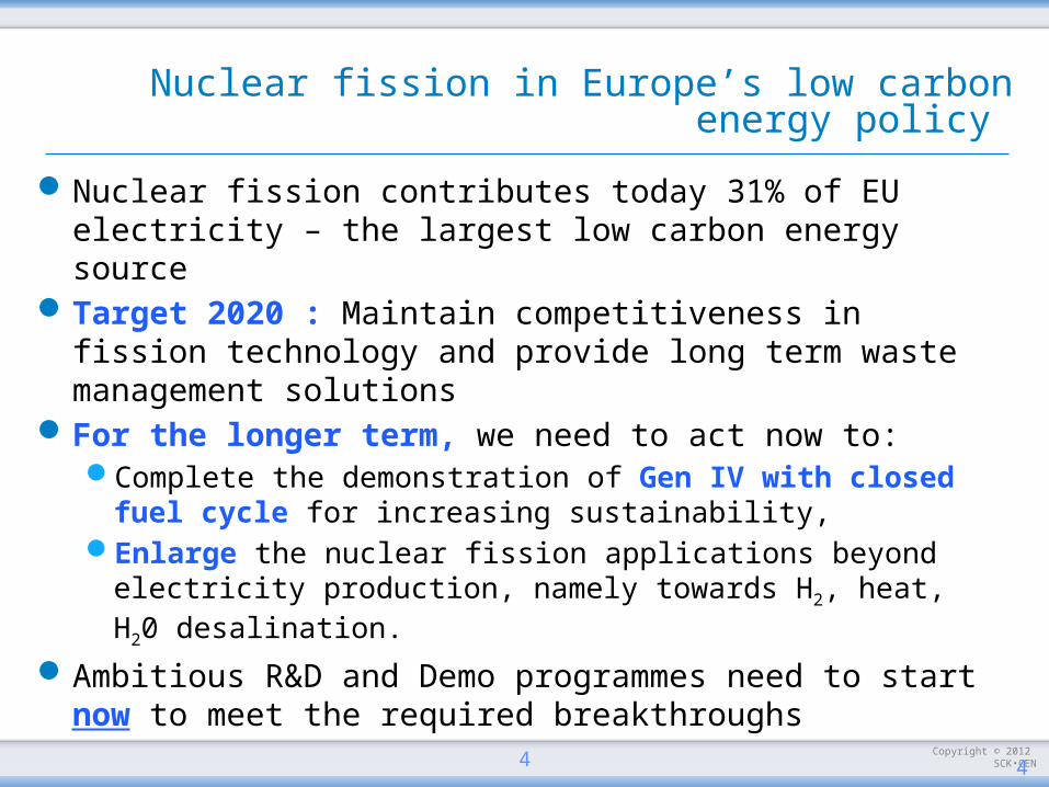
Nuclear fission in Europe’s low carbon energy policy
Nuclear fission contributes today 31% of EU electricity – the largest low carbon energy source
Target 2020 : Maintain competitiveness in fission technology and provide long term waste management solutions
For the longer term, we need to act now to:Complete the demonstration of Gen IV with closed fuel
cycle for increasing sustainability,Enlarge the nuclear fission applications beyond electricity
production, namely towards H2, heat, H20 desalination.
Ambitious R&D and Demo programmes need to start now to meet the required breakthroughs
4

Copyright © 2012 SCK•CEN
wasteminimisation
better use ofresources
reducedproliferation
risks
5
Copyright © 2012 SCK•CEN
Contents
Nuclear energy in EuropeDealing with radioactive wasteSome ADS concepts from the past, within and outside
EuropeSome more recent concepts next presentationConclusion
6

Copyright © 2012 SCK•CEN7
Fission generates High-Level Nuclear Waste
U235
nPu Np Am Cm
Actinides Minor Actinides
Neutron
Uranium Fission
Fuel
U238
n
n
n
U235
U238
Plutonium Neptunium Americium Curium
Minor Actinides
high radiotoxicity long lived wastethat are difficult to store due to:
Long lived (>1,000 years)
Highly radiotoxic
Heat emitting
Copyright © 2012 SCK•CEN8
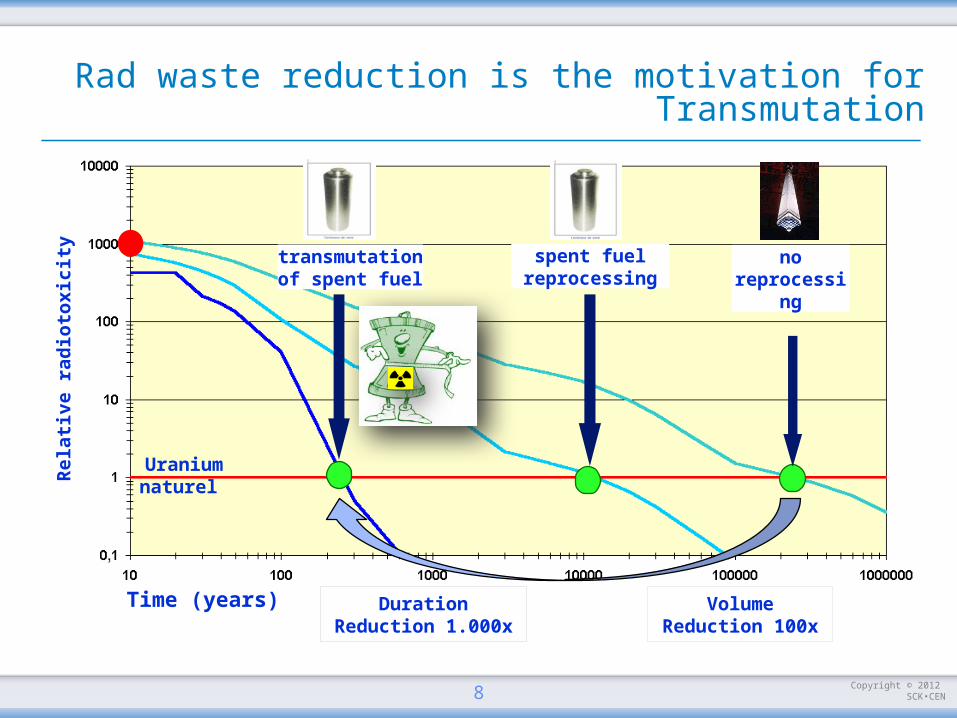
spent fuel reprocessing
no reprocessing
Uraniumnaturel
Time (years)
Rel
ati
ve
rad
ioto
xici
ty
transmutationof spent fuel
Duration Reduction 1.000x
Volume Reduction 100x
Rad waste reduction is the motivation for Transmutation
Copyright © 2012 SCK•CEN99
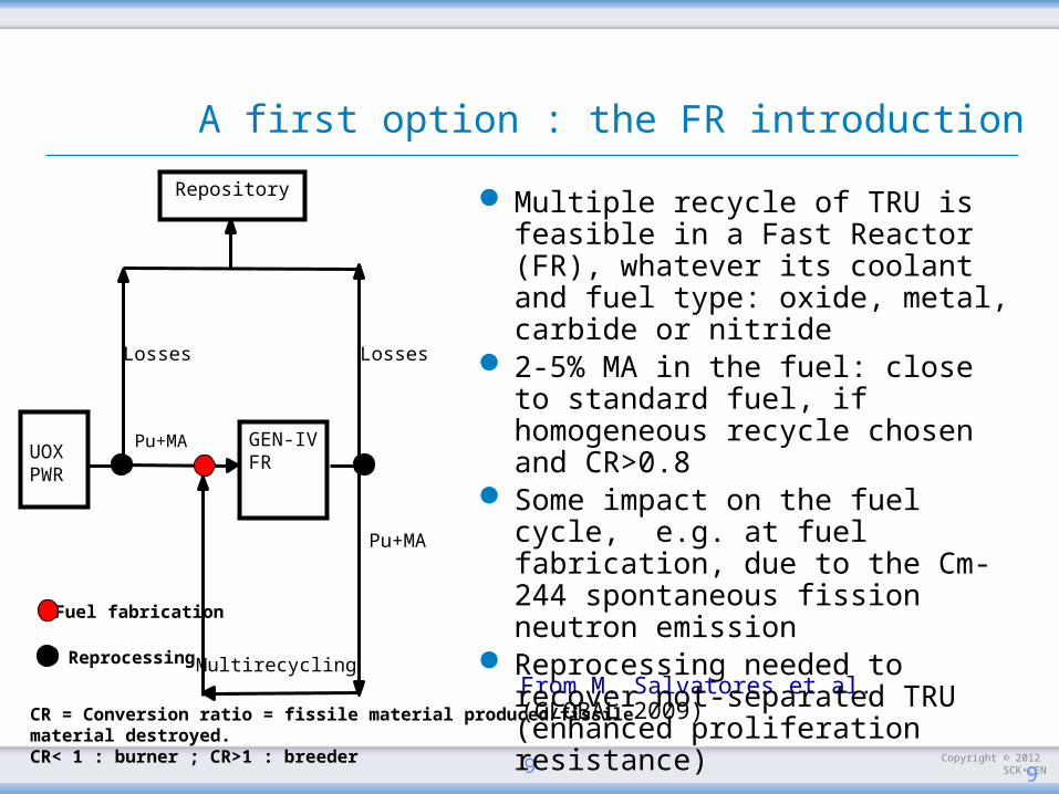
GEN-IVFR
Losses Losses
Pu+MA
Pu+MA
Multirecycling
Repository
UOXPWR
Fuel fabrication
Reprocessing
CR = Conversion ratio = fissile material produced/fissile material destroyed.CR< 1 : burner ; CR>1 : breeder
From M. Salvatores et al. (GLOBAL 2009)
A first option : the FR introduction
Multiple recycle of TRU is feasible in a Fast Reactor (FR), whatever its coolant and fuel type: oxide, metal, carbide or nitride
2-5% MA in the fuel: close to standard fuel, if homogeneous recycle chosen and CR>0.8
Some impact on the fuel cycle, e.g. at fuel fabrication, due to the Cm-244 spontaneous fission neutron emission
Reprocessing needed to recover not-separated TRU (enhanced proliferation resistance)

Copyright © 2012 SCK•CEN1010
multirecycling
multirecycling
Repository
UOXPWR
MOXPWR
Dedicated transmuter system
PuMA+Pu
Pu
Lo
sses
Lo
sses
MA
+P
u
MA
Fuel fabrication
ReprocessingLo
sses
The second option : the ADS scenario
Called "Double strata" Still considering Pu as a
resource Gen-IV FR deployment delayed Pu inventory can be stabilized MA management in dedicated
transmuter systems: e.g. ADS or critical FR with low CR.
Fuel: New fuel (with high MA content) needs to be developed
Reprocessing: to be developed in particular for U-free fuels. Choice of support matrix in fuel is relevant.
Potential impact on the fuel cycle (high decay heat, high neutron emissions)
From M. Salvatores et al. (GLOBAL 2009)
Copyright © 2012 SCK•CEN1111
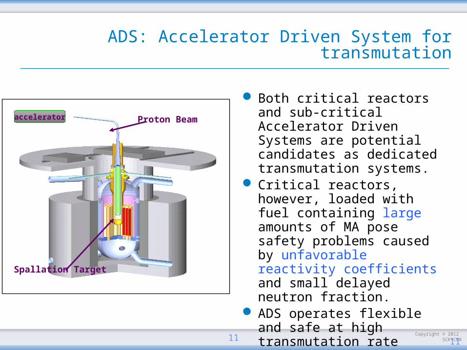
ADS: Accelerator Driven System for transmutation
Both critical reactors and sub-critical Accelerator Driven Systems are potential candidates as dedicated transmutation systems.
Critical reactors, however, loaded with fuel containing large amounts of MA pose safety problems caused by unfavorable reactivity coefficients and small delayed neutron fraction.
ADS operates flexible and safe at high transmutation rate
Proton Beam
Spallation Target
accelerator
Copyright © 2012 SCK•CEN
Contents
Nuclear energy in EuropeDealing with radioactive wasteSome ADS concepts from the past, within and
outside EuropeSome more recent concepts next presentationConclusion
12

Copyright © 2012 SCK•CEN
ADS in Europe: past and present
Energy Amplifier (EA) developed at CERN in the 90’s: devoted to a better use of resources; EA evolved then to XADS
ADONIS project in Belgium (1995-1996): solely devoted to the production of radio-isotopes for the medical industry; ADONIS evolved to MYRRHA in 1997; this project still exists
Both projects (XADS, MYRRHA) have been brought together in FP5 project PDS-XADS FP6 IP-EUROTRANS, finally FP7 CDTPDS-XADS (2002-2004): 80 MWth LBE-cooled and gas-
cooled, 50 MWth small-scaleEUROTRANS (2005-2010): two designs
MYRRHA, 70 MWth small-scale short-term, EFIT, 400 MWth mid-scale long-term
CDT (2009-2012): MYRRHA/FASTEF, 70-100 MWth short-term, sub-critical & critical
13

Copyright © 2012 SCK•CEN14
The EFIT concept
Within the EUROTRANS project, the EFIT concept is developed for the transmutation of MAs
EFIT stays for European Feasibility for Industrial Transmutation
Its main features:ADS with keff (t) ≤ 0,97Lead-cooled sub-critical core (Tin=400 °C, Tout=480°C)MA & Pu Oxide fuel in inert matrix (MgO)several hundreds MW power
14

Copyright © 2012 SCK•CEN
1 Reactor Core 2 Active Zone3 Diagrid4 Primary Pump5 Cylindrical Inner Vessel6 Reactor Vessel7 Reactor Cavity8 Reactor Roof9 Reactor Vessel Support
10 Rotating Plug12 Above Core Structure13 Target Unit14 Steam Generator Unit15 Fuel Handling Machine16 Filter Unit17 Core Instrumentation18 Rotor Lift Machine19 DHR Dip Cooler
EFIT Reactor Assembly
15
Copyright © 2012 SCK•CEN
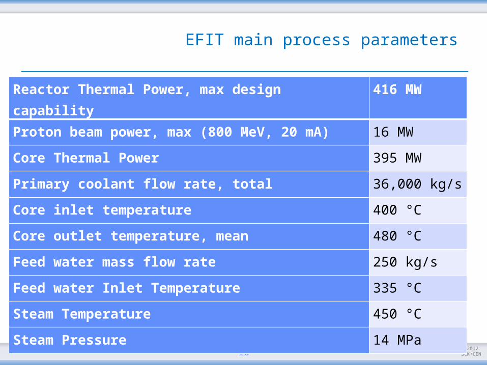
EFIT main process parameters
16
Reactor Thermal Power, max design capability
416 MW
Proton beam power, max (800 MeV, 20 mA) 16 MW
Core Thermal Power 395 MW
Primary coolant flow rate, total 36,000 kg/s
Core inlet temperature 400 °C
Core outlet temperature, mean 480 °C
Feed water mass flow rate 250 kg/s
Feed water Inlet Temperature 335 °C
Steam Temperature 450 °C
Steam Pressure 14 MPa
Copyright © 2012 SCK•CEN
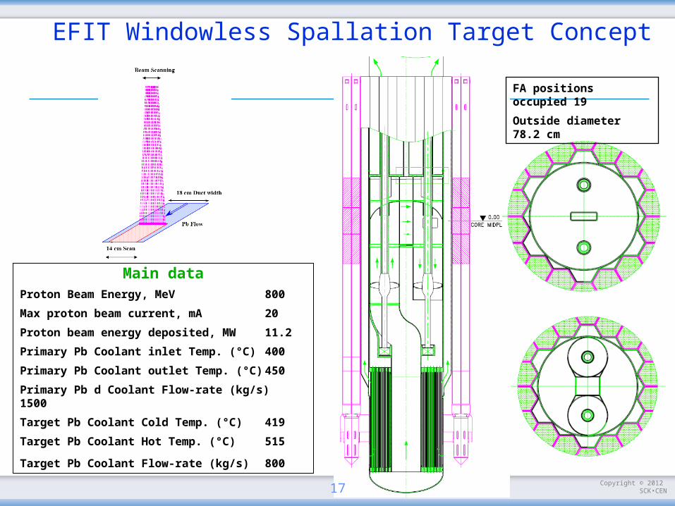
Main dataProton Beam Energy, MeV 800
Max proton beam current, mA 20
Proton beam energy deposited, MW 11.2
Primary Pb Coolant inlet Temp. (°C) 400
Primary Pb Coolant outlet Temp. (°C) 450
Primary Pb d Coolant Flow-rate (kg/s) 1500
Target Pb Coolant Cold Temp. (°C) 419
Target Pb Coolant Hot Temp. (°C) 515
Target Pb Coolant Flow-rate (kg/s) 800
FA positions occupied 19
Outside diameter 78.2 cm
EFIT Windowless Spallation Target Concept
17
Copyright © 2012 SCK•CEN
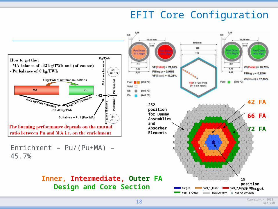
252 position for Dummy Assemblies and Absorber Elements
42 FA
66 FA
72 FA
19 position for Target
Inner, Intermediate, Outer FA Design and Core Section
Enrichment = Pu/(Pu+MA) = 45.7%
EFIT Core Configuration
18
Copyright © 2012 SCK•CEN
Contents
Nuclear energy in EuropeDealing with radioactive wasteSome ADS concepts from the past, within and
outside EuropeSome more recent concepts next presentationConclusion
19
Copyright © 2012 SCK•CEN
ADS outside Europe: past and present
Japan (JAEA):Experimental scale
30 MWth, then 60 MWthCooled by LBE (backup option being sodium)Keff ~ 0,93
Industrial scale800 MWth (see later)
Korea (KAERI)HYPER (Hybrid Power Extraction Reactor) designed since
1997Designed to transmute TC-99 and I-129 coming from PWRs1000 MWth; LBE-cooledKeff ~ 0,98
20
Copyright © 2012 SCK•CEN
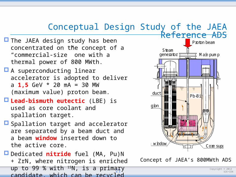
Conceptual Design Study of the JAEA Reference ADS
21
The JAEA design study has been concentrated on the concept of a “commercial-size” one with a thermal power of 800 MWth.
A superconducting linear accelerator is adopted to deliver a 1,5 GeV * 20 mA = 30 MW (maximum value) proton beam.
Lead-bismuth eutectic (LBE) is used as core coolant and spallation target.
Spallation target and accelerator are separated by a beam duct and a beam window inserted down to the active core.
Dedicated nitride fuel (MA, Pu)N + ZrN, where nitrogen is enriched up to 99 % with 15N, is a primary candidate, which can be recycled by a pyrochemical process with recovering 15N.
Concept of JAEA’s 800MWth ADS
Main pump
Beam window
Fuel region
Beam duct
Steamgenerator
Proton beam
Pb-Bi
Core support

Copyright © 2012 SCK•CEN
JAEA Design Study : ADS Plant System
22
Core barrel
Primary pump
Beam ductInner barrel
Steam generator
Guard vessel
Core support
Beam Window
Reactor vessel
Core barrel
Primary pump
Beam ductInner barrelInner barrel
Steam generator
Guard vessel
Core support
Beam Window
Reactor vessel
Copyright © 2012 SCK•CEN
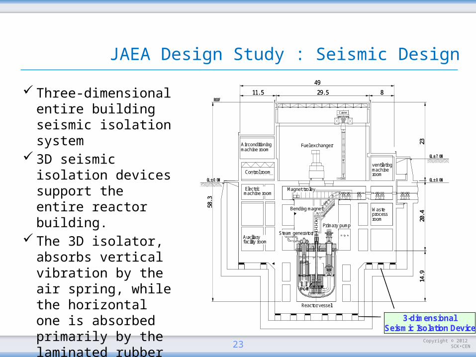
JAEA Design Study : Seismic Design
23
58.3
2320.4
14.9
49
829.511.5
Crane
Fuel exchangerAir conditioning machine room
Control room
Electric machine room
ventilating machine room
Waste process room
Magnet trolley
Bending magnet
Primary pump
Steam generatorAuxiliary facility room
Reactor vessel
3-dimensional Seismic Isolation Device
58.3
2320.4
14.9
49
829.511.5
Crane
Fuel exchangerAir conditioning machine room
Control room
Electric machine room
ventilating machine room
Waste process room
Magnet trolley
Bending magnet
Primary pump
Steam generatorAuxiliary facility room
Reactor vessel
3-dimensional Seismic Isolation Device
Three-dimensional entire building seismic isolation system
3D seismic isolation devices support the entire reactor building.
The 3D isolator, absorbs vertical vibration by the air spring, while the horizontal one is absorbed primarily by the laminated rubber bearing.
Copyright © 2012 SCK•CEN
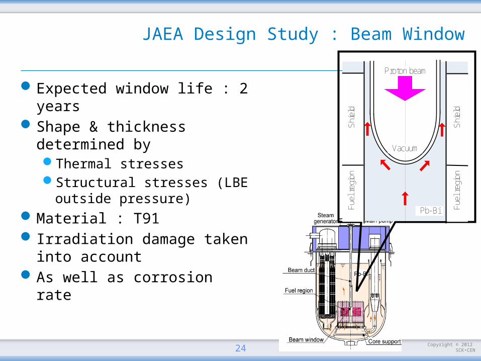
JAEA Design Study : Beam Window
Expected window life : 2 years
Shape & thickness determined byThermal stressesStructural stresses (LBE
outside pressure)Material : T91 Irradiation damage taken into
accountAs well as corrosion rate
24Fue
l reg
ion
Fue
l reg
ion
Shi
eld
Shi
eld
Pb-Bi
Proton beam
Vacuum
Copyright © 2012 SCK•CEN
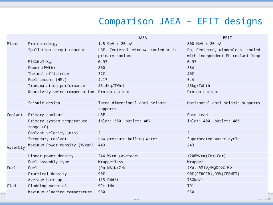
Comparison JAEA – EFIT designs
25
JAEA EFIT
Plant Proton energy 1.5 GeV x 20 mA 800 MeV x 20 mASpallation target concept LBE, Centered, window, cooled with primary coolant Pb, Centered, windowless, cooled with
independent Pb coolant loop
Maximum keff 0.97 0.97
Power (MWth) 800 384
Thermal efficiency 32% 40%
Fuel amount (HMt) 4.17 5.4
Transmutation performance 43.4kg/TWhth 45kg/TWhthReactivity swing compensation Proton current Proton current
Seismic design Three-dimensional anti-seismic supports Horizontal anti-seismic supports
Coolant Primary coolant LBE Pure LeadPrimary system temperature range (C) inlet: 300, outlet: 407 inlet: 400, outlet: 480
Coolant velocity (m/s) 2 2
Secondary coolant Low pressure boiling water Superheated water cycle
AssemblyMaximum Power density (W/cm3) 449 243
Linear power density 244 W/cm (average) <200W/cm(Cer-Cer)
Fuel assembly type Wrapperless Wrapper
Fuel Fuel (Pu,MA)N+ZrN (Pu, AM)O2+MgO(or Mo)
Practical density 90% 90%(CERCER),93%(CERMET)
Average burn-up 115 GWd/t 78GWd/t
Clad Cladding material 9Cr-1Mo T91Maximum cladding temperature 580 550

Copyright © 2012 SCK•CEN
Contents
Nuclear energy in EuropeDealing with radioactive wasteSome ADS concepts from the past, within and outside
EuropeSome more recent concepts next presentationConclusion
26
Copyright © 2012 SCK•CEN
Conclusion
Advanced nuclear fuel cycles are required to meet now the objective of making nuclear fission sustainable
The objectives of sustainability: waste minimisation, better use of the natural resources and reduced proliferation risks can be met with both fast reactors and dedicated burners (ADS)
Design studies have been performed within and outside Europe
Demonstrations (prototypes) should be planned and realized, to go from paper work to real work
Through the new MYRRHA research infrastructure (see next presentation), Belgium is contributing to this international endeavour.
27

Copyright © 2012 SCK•CEN
Copyright © 2012 - SCKCEN
PLEASE NOTE! This presentation contains preliminary data for dedicated use ONLY and may not be cited without the explicit permission of the author.
If this has been obtained, please reference it as a “personal communication. Copyright SCK•CEN”.
SCK•CENStudiecentrum voor Kernenergie
Centre d'Etude de l'Energie NucléaireBelgian Nuclear Research Centre
Stichting van Openbaar Nut Fondation d'Utilité Publique Foundation of Public Utility
Registered Office: Avenue Herrmann-Debrouxlaan 40 – BE-1160 BRUSSELSOperational Office: Boeretang 200 – BE-2400 MOL