copyright 2007-2009 fujitsu limited, 1-1, …€¦ · copyright 2007-2009 fujitsu limited, 1-1,...
TRANSCRIPT


Copyright 2007-2009 FUJITSU LIMITED, 1-1, Kamikodanaka 4-chome, Nakahara-ku, Kawasaki-shi, Kanagawa-ken 211-8588, Japan. All rights reserved.Sun Microsystems, Inc. provided technical input and review on portions of this material. Sun Microsystems, Inc. and Fujitsu Limited each own or control intellectual property rights relating to products and technology described in this document, and such products, technology and this document are protected by copyright laws, patents and other intellectual property laws and international treaties. The intellectual property rights of Sun Microsystems, Inc. and Fujitsu Limited in such products, technology and this document include, without limitation, one or more of the United States patents listed at http://www.sun.com/patents and one or more additional patents or patent applications in the United States or other countries.This document and the product and technology to which it pertains are distributed under licenses restricting their use, copying, distribution, and decompilation. No part of such product or technology, or of this document, may be reproduced in any form by any means without prior written authorization of Fujitsu Limited and Sun Microsystems, Inc., and their applicable licensors, if any. The furnishing of this document to you does not give you any rights or licenses, express or implied, with respect to the product or technology to which it pertains, and this document does not contain or represent any commitment of any kind on the part of Fujitsu Limited or Sun Microsystems, Inc., or any affiliate of either of them.This document and the product and technology described in this document may incorporate third-party intellectual property copyrighted by and/or licensed from suppliers to Fujitsu Limited and/or Sun Microsystems, Inc., including software and font technology.Per the terms of the GPL or LGPL, a copy of the source code governed by the GPL or LGPL, as applicable, is available upon request by the End User. Please contact Fujitsu Limited or Sun Microsystems, Inc.This distribution may include materials developed by third parties.Parts of the product may be derived from Berkeley BSD systems, licensed from the University of California. UNIX is a registered trademark in the U.S. and in other countries, exclusively licensed through X/Open Company, Ltd.Sun, Sun Microsystems, the Sun logo, Java, Netra, Solaris, Sun Ray, Answerbook2, docs.sun.com, OpenBoot, and Sun Fire are trademarks or registered trademarks of Sun Microsystems, Inc., or its subsidiaries, in the U.S. and other countries.Fujitsu and the Fujitsu logo are registered trademarks of Fujitsu Limited.All SPARC trademarks are used under license and are registered trademarks of SPARC International, Inc. in the U.S. and other countries. Products bearing SPARC trademarks are based upon architecture developed by Sun Microsystems, Inc.SPARC64 is a trademark of SPARC International, Inc., used under license by Fujitsu Microelectronics, Inc. and Fujitsu Limited.The OPEN LOOK and Sun™ Graphical User Interface was developed by Sun Microsystems, Inc. for its users and licensees. Sun acknowledges the pioneering efforts of Xerox in researching and developing the concept of visual or graphical user interfaces for the computer industry. Sun holds a non-exclusive license from Xerox to the Xerox Graphical User Interface, which license also covers Sun’s licensees who implement OPEN LOOK GUIs and otherwise comply with Sun’s written license agreements.United States Government Rights - Commercial use. U.S. Government users are subject to the standard government user license agreements of Sun Microsystems, Inc. and Fujitsu Limited and the applicable provisions of the FAR and its supplements. Disclaimer: The only warranties granted by Fujitsu Limited, Sun Microsystems, Inc. or any affiliate of either of them in connection with this document or any product or technology described herein are those expressly set forth in the license agreement pursuant to which the product or technology is provided. EXCEPT AS EXPRESSLY SET FORTH IN SUCH AGREEMENT, FUJITSU LIMITED, SUN MICROSYSTEMS, INC. AND THEIR AFFILIATES MAKE NO REPRESENTATIONS OR WARRANTIES OF ANY KIND (EXPRESS OR IMPLIED) REGARDING SUCH PRODUCT OR TECHNOLOGY OR THIS DOCUMENT, WHICH ARE ALL PROVIDED AS IS, AND ALL EXPRESS OR IMPLIED CONDITIONS, REPRESENTATIONS AND WARRANTIES, INCLUDING WITHOUT LIMITATION ANY IMPLIED WARRANTY OF MERCHANTABILITY, FITNESS FOR A PARTICULAR PURPOSE OR NON-INFRINGEMENT, ARE DISCLAIMED, EXCEPT TO THE EXTENT THAT SUCH DISCLAIMERS ARE HELD TO BE LEGALLY INVALID. Unless otherwise expressly set forth in such agreement, to the extent allowed by applicable law, in no event shall Fujitsu Limited, Sun Microsystems, Inc. or any of their affiliates have any liability to any third party under any legal theory for any loss of revenues or profits, loss of use or data, or business interruptions, or for any indirect, special, incidental or consequential damages, even if advised of the possibility of such damages.DOCUMENTATION IS PROVIDED “AS IS” AND ALL EXPRESS OR IMPLIED CONDITIONS, REPRESENTATIONS AND WARRANTIES, INCLUDING ANY IMPLIED WARRANTY OF MERCHANTABILITY, FITNESS FOR A PARTICULAR PURPOSE OR NON-INFRINGEMENT, ARE DISCLAIMED, EXCEPT TO THE EXTENT THAT SUCH DISCLAIMERS ARE HELD TO BE LEGALLY INVALID.
PleaseRecycle

Copyright 2007-2009 FUJITSU LIMITED, 1-1, Kamikodanaka 4-chome, Nakahara-ku, Kawasaki-shi, Kanagawa-ken 211-8588, Japon. Tous droits réservés.Entrée et revue tecnical fournies par Sun Microsystems, Incl sur des parties de ce matériel.Sun Microsystems, Inc. et Fujitsu Limited détiennent et contrôlent toutes deux des droits de propriété intellectuelle relatifs aux produits et technologies décrits dans ce document. De même, ces produits, technologies et ce document sont protégés par des lois sur le copyright, des brevets, d’autres lois sur la propriété intellectuelle et des traités internationaux. Les droits de propriété intellectuelle de Sun Microsystems, Inc. et Fujitsu Limited concernant ces produits, ces technologies et ce document comprennent, sans que cette liste soit exhaustive, un ou plusieurs des brevets déposés aux États-Unis et indiqués à l’adresse http://www.sun.com/patents de même qu’un ou plusieurs brevets ou applications brevetées supplémentaires aux États-Unis et dans d’autres pays.Ce document, le produit et les technologies afférents sont exclusivement distribués avec des licences qui en restreignent l’utilisation, la copie, la distribution et la décompilation. Aucune partie de ce produit, de ces technologies ou de ce document ne peut être reproduite sous quelque forme que ce soit, par quelque moyen que ce soit, sans l’autorisation écrite préalable de Fujitsu Limited et de Sun Microsystems, Inc., et de leurs éventuels bailleurs de licence. Ce document, bien qu’il vous ait été fourni, ne vous confère aucun droit et aucune licence, expresses ou tacites, concernant le produit ou la technologie auxquels il se rapporte. Par ailleurs, il ne contient ni ne représente aucun engagement, de quelque type que ce soit, de la part de Fujitsu Limited ou de Sun Microsystems, Inc., ou des sociétés affiliées.Ce document, et le produit et les technologies qu’il décrit, peuvent inclure des droits de propriété intellectuelle de parties tierces protégés par copyright et/ou cédés sous licence par des fournisseurs à Fujitsu Limited et/ou Sun Microsystems, Inc., y compris des logiciels et des technologies relatives aux polices de caractères.Par limites du GPL ou du LGPL, une copie du code source régi par le GPL ou LGPL, comme applicable, est sur demande vers la fin utilsateur disponible; veuillez contacter Fujitsu Limted ou Sun Microsystems, Inc.Cette distribution peut comprendre des composants développés par des tierces parties.Des parties de ce produit pourront être dérivées des systèmes Berkeley BSD licenciés par l’Université de Californie. UNIX est une marque déposée aux Etats-Unis et dans d’autres pays et licenciée exclusivement par X/Open Company, Ltd.Sun, Sun Microsystems, le logo Sun, Java, Netra, Solaris, Sun Ray, Answerbook2, docs.sun.com, OpenBoot, et Sun Fire sont des marques de fabrique ou des marques déposées de Sun Microsystems, Inc., ou ses filiales, aux Etats-Unis et dans d’autres pays.Fujitsu et le logo Fujitsu sont des marques déposées de Fujitsu Limited.Toutes les marques SPARC sont utilisées sous licence et sont des marques de fabrique ou des marques déposées de SPARC International, Inc. aux Etats-Unis et dans d’autres pays. Les produits portant les marques SPARC sont basés sur une architecture développée par Sun Microsystems, Inc.SPARC64 est une marques déposée de SPARC International, Inc., utilisée sous le permis par Fujitsu Microelectronics, Inc. et Fujitsu Limited.L’interface d’utilisation graphique OPEN LOOK et Sun™ a été développée par Sun Microsystems, Inc. pour ses utilisateurs et licenciés. Sun reconnaît les efforts de pionniers de Xerox pour la recherche et le développement du concept des interfaces d’utilisation visuelle ou graphique pour l’industrie de l’informatique. Sun détient une license non exclusive de Xerox sur l’interface d’utilisation graphique Xerox, cette licence couvrant également les licenciés de Sun qui mettent en place l’interface d’utilisation graphique OPEN LOOK et qui, en outre, se conforment aux licences écrites de Sun.Droits du gouvernement américain - logiciel commercial. Les utilisateurs du gouvernement américain sont soumis aux contrats de licence standard de Sun Microsystems, Inc. et de Fujitsu Limited ainsi qu’aux clauses applicables stipulées dans le FAR et ses suppléments. Avis de non-responsabilité: les seules garanties octroyées par Fujitsu Limited, Sun Microsystems, Inc. ou toute société affiliée de l’une ou l’autre entité en rapport avec ce document ou tout produit ou toute technologie décrit(e) dans les présentes correspondent aux garanties expressément stipulées dans le contrat de licence régissant le produit ou la technologie fourni(e). SAUF MENTION CONTRAIRE EXPRESSÉMENT STIPULÉE DANS CE CONTRAT, FUJITSU LIMITED, SUN MICROSYSTEMS, INC. ET LES SOCIÉTÉS AFFILIÉES REJETTENT TOUTE REPRÉSENTATION OU TOUTE GARANTIE, QUELLE QU’EN SOIT LA NATURE (EXPRESSE OU IMPLICITE) CONCERNANT CE PRODUIT, CETTE TECHNOLOGIE OU CE DOCUMENT, LESQUELS SONT FOURNIS EN L’ÉTAT. EN OUTRE, TOUTES LES CONDITIONS, REPRÉSENTATIONS ET GARANTIES EXPRESSES OU TACITES, Y COMPRIS NOTAMMENT TOUTE GARANTIE IMPLICITE RELATIVE À LA QUALITÉ MARCHANDE, À L’APTITUDE À UNE UTILISATION PARTICULIÈRE OU À L’ABSENCE DE CONTREFAÇON, SONT EXCLUES, DANS LA MESURE AUTORISÉE PAR LA LOI APPLICABLE. Sauf mention contraire expressément stipulée dans ce contrat, dans la mesure autorisée par la loi applicable, en aucun cas Fujitsu Limited, Sun Microsystems, Inc. ou l’une de leurs filiales ne sauraient être tenues responsables envers une quelconque partie tierce, sous quelque théorie juridique que ce soit, de tout manque à gagner ou de perte de profit, de problèmes d’utilisation ou de perte de données, ou d’interruptions d’activités, ou de tout dommage indirect, spécial, secondaire ou consécutif, même si ces entités ont été préalablement informées d’une telle éventualité.LA DOCUMENTATION EST FOURNIE “EN L’ETAT” ET TOUTES AUTRES CONDITIONS, DECLARATIONS ET GARANTIES EXPRESSES OU TACITES SONT FORMELLEMENT EXCLUES, DANS LA MESURE AUTORISEE PAR LA LOI APPLICABLE, Y COMPRIS NOTAMMENT TOUTE GARANTIE IMPLICITE RELATIVE A LA QUALITE MARCHANDE, A L’APTITUDE A UNE UTILISATION PARTICULIERE OU A L’ABSENCE DE CONTREFACON.

Table of Contents
Table of Contents
Chapter 1 Flexible, Mainframe-Class Compute Power for the Datacenter . . . . . . . . . . . . . . . . . . . . . . . . . . . . . . . . . . . . . . . . 1
1.1 Introducing the Fujitsu SPARC Enterprise Server Family . . . . . 1
1.2 Fujitsu SPARC Enterprise Server Family Overview. . . . . . . . . . 3
1.3 Meeting the Needs of Commercial and Scientific Computing . . 5
Chapter 2 System Architecture . . . . . . . . . . . . . . . . . . . . . . . . . . . . . . . . 6
2.1 System Component Overview . . . . . . . . . . . . . . . . . . . . . . . . . . 6
2.2 Midrange Systems — Fujitsu SPARC Enterprise M4000 and Fujitsu SPARC Enterprise M5000 . . . . . . . . . . . . . . . . . . . . . . 13
2.3 High-End Systems — Fujitsu SPARC Enterprise M8000 and Fujitsu SPARC Enterprise M9000 . . . . . . . . . . . . . . . . . . . . . . 15
Chapter 3 System Bus Architecture — Jupiter Interconnect . . . . . . . 18
3.1 Fujitsu SPARC Enterprise Server Interconnect Architecture . . . . . . . . . . . . . . . . . . . . . . . . . . . . . . . . . . . . . . . 18
3.2 System Interconnect Reliability Features. . . . . . . . . . . . . . . . . 21
3.3 Scalable Performance . . . . . . . . . . . . . . . . . . . . . . . . . . . . . . . 22
Chapter 4 Fujitsu SPARC64 VI/SPARC64 VII Processors . . . . . . . . . . 24
4.1 SPARC64 Series . . . . . . . . . . . . . . . . . . . . . . . . . . . . . . . . . . . 24
4.2 SPARC64 VI Overview. . . . . . . . . . . . . . . . . . . . . . . . . . . . . . . 25
4.3 SPARC64 VII Overview . . . . . . . . . . . . . . . . . . . . . . . . . . . . . . 26
4.4 SPARC64 VII micro-architecture . . . . . . . . . . . . . . . . . . . . . . . 27
4.5 Cache System . . . . . . . . . . . . . . . . . . . . . . . . . . . . . . . . . . . . . 31
4.6 Reliability, Availability, and Serviceability (RAS) Functions . . . 33
Chapter 5 I/O Subsystem . . . . . . . . . . . . . . . . . . . . . . . . . . . . . . . . . . . . 36
5.1 I/O Subsystem Architecture . . . . . . . . . . . . . . . . . . . . . . . . . . . 36
5.2 Internal Peripherals . . . . . . . . . . . . . . . . . . . . . . . . . . . . . . . . . 39
5.3 External I/O Expansion Unit . . . . . . . . . . . . . . . . . . . . . . . . . . . 40
Chapter 6 Reliability, Availability, and Serviceability . . . . . . . . . . . . . 42
6.1 Redundant and Hot-Swap Components . . . . . . . . . . . . . . . . . 42
6.2 Dynamic Domains . . . . . . . . . . . . . . . . . . . . . . . . . . . . . . . . . . 43
6.3 Dynamic Reconfiguration . . . . . . . . . . . . . . . . . . . . . . . . . . . . . 46
6.4 Advanced Reliability Features . . . . . . . . . . . . . . . . . . . . . . . . . 47
6.5 Error Detection, Diagnosis, and Recovery . . . . . . . . . . . . . . . . 48
Chapter 7 System Management . . . . . . . . . . . . . . . . . . . . . . . . . . . . . . 49
7.1 Extended System Control Facility . . . . . . . . . . . . . . . . . . . . . . 49
i
Table of Contents
ii
Chapter 8 The Solaris 10 Operating System . . . . . . . . . . . . . . . . . . . . 53
8.1 Observability and Performance . . . . . . . . . . . . . . . . . . . . . . . . 53
8.2 Availability . . . . . . . . . . . . . . . . . . . . . . . . . . . . . . . . . . . . . . . . 55
8.3 Security . . . . . . . . . . . . . . . . . . . . . . . . . . . . . . . . . . . . . . . . . . 57
8.4 Virtualization and Resource Management . . . . . . . . . . . . . . . . 58
Chapter 9 Summary . . . . . . . . . . . . . . . . . . . . . . . . . . . . . . . . . . . . . . . . 59
Flexible, Mainframe-Class Compute Power for the Datacenter
1. Flexible, Mainframe-Class Compute Power for the Datacenter
Reliance upon technology within enterprises is greater than ever. Today, compute systems play a critical role in every function from product design to customer order fulfillment. In many cases, business success is dependent on continuous availability of IT services. Once only required in pockets of the datacenter, mainframe-class reliability and serviceability are now essential for systems throughout the enterprise. In addition, powering datacenter servers and keeping services running through a power outage are significant concerns.
While availability is a top priority, costs must also remain in budget and operational familiarity maintained. To deliver networked services as efficiently and economically as possible, enterprises look to maximize use of every IT asset through consolidation and virtualization strategies. As a result, modern IT system requirements reach far beyond simple measures of compute capacity. Organizations need highly flexible servers with built-in virtualization capabilities and associated tools, technologies, and processes that work to optimize sever utilization. With budgets still in mind, new computing infrastructures must also help protect current investments in technology and training.
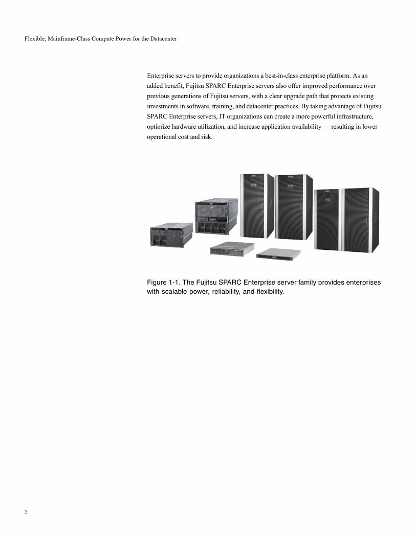
1.1 Introducing the Fujitsu SPARC Enterprise Server FamilyFujitsu SPARC Enterprise™ servers are highly reliable, easy to manage, vertically-scalable systems with all of the benefits of traditional mainframes and none of the associated cost, complexity, or vendor lock-in (Figure 1-1). In fact, Fujitsu SPARC Enterprise servers deliver a mainframe-class system architecture at open systems prices. With symmetric multiprocessing (SMP) scalability from one to 64 processors, memory subsystems as large as 4 TB, and high-throughput I/O architectures, Fujitsu SPARC Enterprise servers easily perform the heavy lifting required by consolidated workloads. Furthermore, Fujitsu SPARC Enterprise servers run the powerful Solaris™ 10 Operating System (OS) and include leading virtualization technologies. By offering Dynamic Domains (=Partitioning feature), eXtended System Boards, Dynamic Reconfiguration, and Solaris Containers technology, Fujitsu SPARC Enterprise servers bring mainframe-class, sophisticated resource control to an open systems compute platform.
Massive compute power, a resilient system architecture, flexible resource control features, and the advanced capabilities of the Solaris 10 OS combine in Fujitsu SPARC
1
Flexible, Mainframe-Class Compute Power for the Datacenter
Enterprise servers to provide organizations a best-in-class enterprise platform. As an added benefit, Fujitsu SPARC Enterprise servers also offer improved performance over previous generations of Fujitsu servers, with a clear upgrade path that protects existing investments in software, training, and datacenter practices. By taking advantage of Fujitsu SPARC Enterprise servers, IT organizations can create a more powerful infrastructure, optimize hardware utilization, and increase application availability — resulting in lower operational cost and risk.
Figure 1-1. The Fujitsu SPARC Enterprise server family provides enterprises with scalable power, reliability, and flexibility.
2

Flexible, Mainframe-Class Compute Power for the Datacenter
1.2 Fujitsu SPARC Enterprise Server Family OverviewThe members of the Fujitsu SPARC Enterprise server family share many of the same characteristics which provide power, reliability, and flexibility to enterprises. Fujitsu SPARC Enterprise servers all feature a balanced, highly scalable SMP design that utilizes the latest generation of SPARC64 processors connected to memory and I/O by a new high-speed, low latency system interconnect, delivering exceptional throughput to software applications. Also architected to reduce planned and unplanned downtime, Fujitsu SPARC Enterprise servers include stellar reliability, availability, and serviceability capabilities to avoid outages and reduce recovery time. Design features of Fujitsu SPARC Enterprise servers, such as advanced CPU integration and data path integrity, memory Extended ECC and memory mirroring, end-to-end data protection, hot-swappable components, fault resilient power options, and hardware redundancy boost the reliability of these servers.
Fujitsu SPARC Enterprise servers also provide unmatched configuration flexibility. As in other Fujitsu high-end servers, administrators can use Dynamic Domains to physically divide a single Fujitsu SPARC Enterprise server into multiple electrically isolated partitions, each running independent instances of the Solaris Operating System (Solaris OS). Hardware or software failures in one Dynamic Domains do not affect applications running in other domains, unless the failed resource is shared across both domains.
Dynamic Reconfiguration can then reallocate hardware resources among Dynamic Domains — without interrupting critical systems. Fujitsu SPARC Enterprise servers advance resource control one-step further with eXtended System Board technology, enabling allocation of sub-system board resources such as CPUs, memory, and I/O components to Dynamic Domains. The fine-grain resource control provided by eXtended System Board technology helps enterprises to further optimize resource utilization.
Adding even more value, the range of compute power offered by the Fujitsu SPARC Enterprise server family provides the levels of vertical scalability required for many deployment classes, enabling enterprises to match the right system to the job at hand. Rackmount Fujitsu SPARC Enterprise M4000 and Fujitsu SPARC Enterprise M5000 are economical, powerful, and reliable servers well-suited for mid-range system requirements, while Fujitsu SPARC Enterprise M8000 and Fujitsu SPARC Enterprise M9000 deliver the massive processing power needed for high-end computing (Table 1-1).
3

Flexible, Mainframe-Class Compute Power for the Datacenter
Table 1-1. The Fujitsu SPARC Enterprise server family supports midrange and high-end compute requirements.
*: When 8 GB DIMM is available.
Fujitsu SPARC Enterprise M4000
Fujitsu SPARC Enterprise M5000
Fujitsu SPARC Enterprise M8000
Fujitsu SPARC Enterprise M9000 (32 CPU configuration)
Fujitsu SPARC Enterprise M9000(64 CPU configuration)
Enclosure • 6 rack units • 10 rack units • One cabinet • One cabinet • Two cabinets
SPARC64 VI Processors
• 2.15 GHz• 5 MB L2 cache• Up to four
dual-core chips
• 2.15 GHz• 5 MB L2 cache• Up to eight dual-
core chips
• 2.28 GHz/2.4 GHz• 5 - 6 MB L2 cache• Up to 16
dual-core chips
• 2.28 GHz/2.4 GHz• 5 - 6 MB L2 cache• Up to 32
dual-core chips
• 2.28 GHz/2.4 GHz• 5 - 6 MB L2 cache• Up to 64
dual-core chips
SPARC64 VII Processors
• 2.4 GHz/2.53 GHz• 5 MB/5.5 MB L2
cache• Up to four
quad-core chips
• 2.4 GHz/2.53 GHz• 5 MB/5.5 MB L2
cache• Up to eight quad-
core chips
• 2.52 GHz/2.88 GHz• 6 MB L2 cache• Up to 16
quad-core chips
• 2.52 GHz/2.88 GHz• 6 MB L2 cache• Up to 32
quad-core chips
• 2.52 GHz/2.88 GHz• 6 MB L2 cache• Up to 64
quad-core chips
Memory • Up to 256 GB(*)• 32 DIMM slots
• Up to 512 GB(*)• 64 DIMM slots
• Up to 1 TB• 128 DIMM slots
• Up to 2 TB• 256 DIMM slots
• Up to 4 TB• 512 DIMM slots
Internal I/O Slots
• Four PCIe• One PCI-X
• Eight PCIe• Two PCI-X
• 32 PCIe • 64 PCIe • 128 PCIe
External I/O Chassis
• Up to two units • Up to four units • Up to 8 units • Up to 16 units • Up to 16 units
Internal Storage
• Serial Attached SCSI
• Up to two drives
• Serial Attached SCSI
• Up to four drives
• Serial Attached SCSI
• Up to 16 drives
• Serial Attached SCSI
• Up to 32 drives
• Serial Attached SCSI
• Up to 64 drives
Dynamic Domains
• Up to two • Up to four • Up to 16 • Up to 24 • Up to 24
4
Flexible, Mainframe-Class Compute Power for the Datacenter
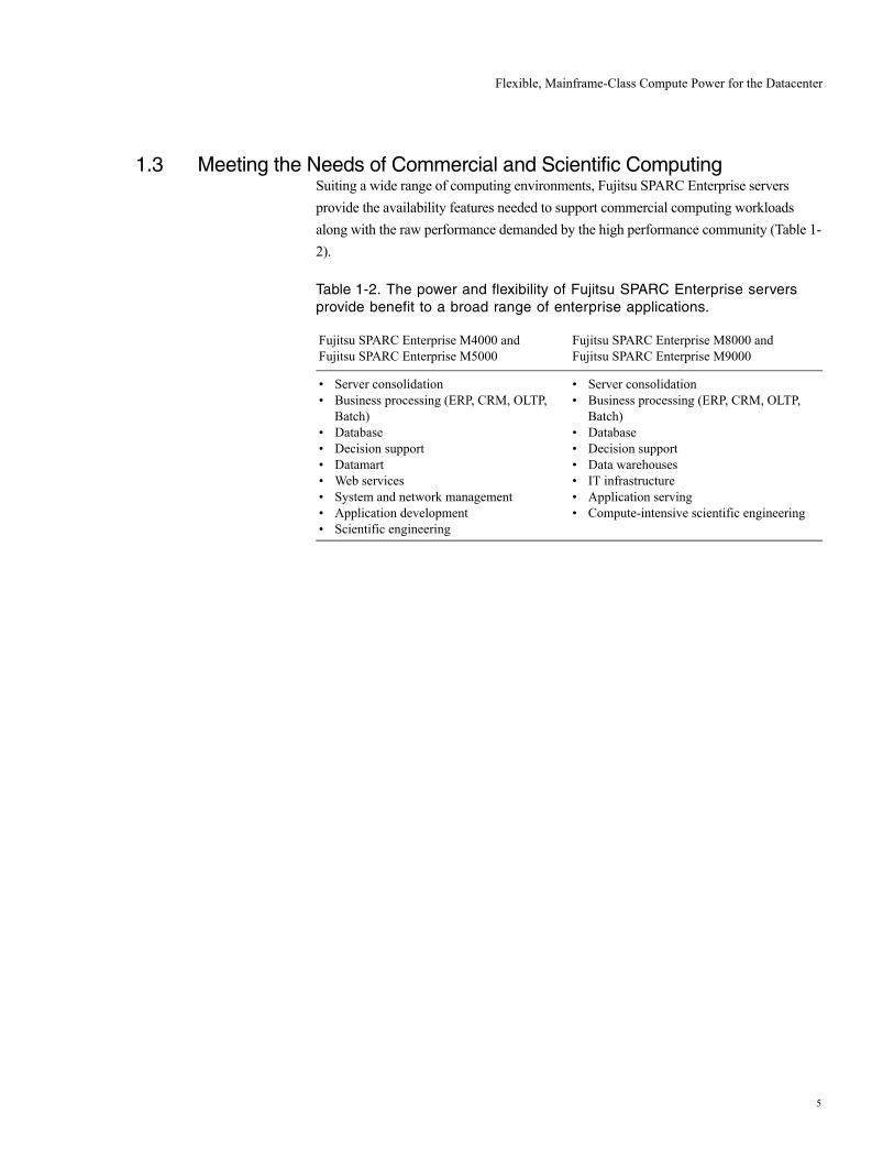
1.3 Meeting the Needs of Commercial and Scientific ComputingSuiting a wide range of computing environments, Fujitsu SPARC Enterprise servers provide the availability features needed to support commercial computing workloads along with the raw performance demanded by the high performance community (Table 1-2).
Table 1-2. The power and flexibility of Fujitsu SPARC Enterprise servers provide benefit to a broad range of enterprise applications.
Fujitsu SPARC Enterprise M4000 and Fujitsu SPARC Enterprise M5000
Fujitsu SPARC Enterprise M8000 and Fujitsu SPARC Enterprise M9000
• Server consolidation• Business processing (ERP, CRM, OLTP,
Batch)• Database• Decision support• Datamart• Web services• System and network management• Application development• Scientific engineering
• Server consolidation• Business processing (ERP, CRM, OLTP,
Batch)• Database• Decision support• Data warehouses• IT infrastructure• Application serving• Compute-intensive scientific engineering
5
System Architecture
2. System Architecture
Continually challenged by growing workloads and demands to do more with less, IT organizations realize that meeting processing requirements with fewer, more powerful systems holds economic advantages. The Fujitsu SPARC Enterprise server system interconnect, processors, memory subsystem, and I/O subsystem work together to create a scalable, high-performance platform ready to address server consolidation needs. By taking advantage of Fujitsu SPARC Enterprise servers, organizations can load multiple projects onto a single platform and accelerate application execution at lower costs.
2.1 System Component OverviewThe design of Fujitsu SPARC Enterprise servers specifically focuses on delivering high reliability, outstanding performance, and true SMP scalability. The characteristics and capabilities of every subsystem within these servers work toward this goal. The high-bandwidth system bus, powerful SPARC64 VI and SPARC64 VII processor chips, high-density memory option, high-speed PCI Express (PCIe), and PCI-extended (PCI-X) expansion slots of the SPARC Enterprise provide not only reliable scaling for enterprise applications but also high-level operational time and throughput.
2.1.1 System InterconnectBased on mainframe technology, the Jupiter system interconnect enables performance scalability and reliability for Fujitsu SPARC Enterprise servers. Multiple system controllers and crossbar units provide point-to-point connections between CPU, memory, and I/O subsystems. Providing more than one bus route between components enhances performance and enables system operation to continue in the event of a faulty switch. Indeed, the system interconnect used in these servers delivers as much as 737 GB/second of peak bandwidth, offering 5.5x more system throughput than Fujitsu’s previous generation of high-end servers. Additional technical details for the system interconnect on each Fujitsu SPARC Enterprise server are found in Chapter 3 – System Bus Architecture.
6
System Architecture
2.1.2 The SPARC64 VI/SPARC64 VII ProcessorsThe SPARC Enterprise M4000, M5000, M8000, and M9000 use the SPARC64 VI processor and SPARC64 VII processor developed by Fujitsu. The SPARC64 VI and SPARC64 VII processors, which have multi-core (two cores for the SPARC64 VI and four cores for SPARC64 VII) and multi-threading architecture, have been designed based on experience in the mainframe computer field accumulated over several decades in pursuit of excellence in reliability and speed. They adopt advanced technology (90 nm for the SPARC64 VI and 65 nm for SPARC64 VII) with power consumption below 150 W. Moreover, because the SPARC64 VII processor can be mounted in a unit in which the SPARC64 VI processor is mounted, system performance can be expanded according to the customer's needs. Other detailed technical information about the SPARC64 VI and SPARC64 VII processors is contained in Chapter 4 – SPARC64 VI/SPARC64 VII Processors.
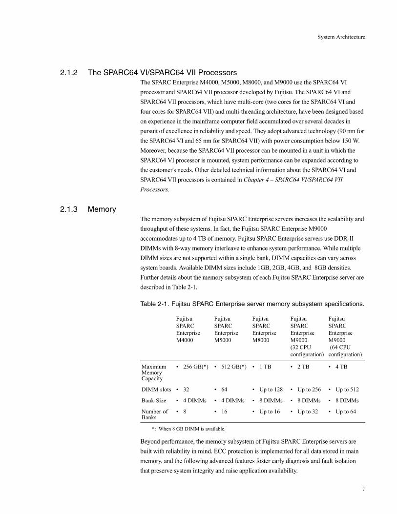
2.1.3 MemoryThe memory subsystem of Fujitsu SPARC Enterprise servers increases the scalability and throughput of these systems. In fact, the Fujitsu SPARC Enterprise M9000 accommodates up to 4 TB of memory. Fujitsu SPARC Enterprise servers use DDR-II DIMMs with 8-way memory interleave to enhance system performance. While multiple DIMM sizes are not supported within a single bank, DIMM capacities can vary across system boards. Available DIMM sizes include 1GB, 2GB, 4GB, and 8GB densities. Further details about the memory subsystem of each Fujitsu SPARC Enterprise server are described in Table 2-1.
Table 2-1. Fujitsu SPARC Enterprise server memory subsystem specifications.
*: When 8 GB DIMM is available.
Beyond performance, the memory subsystem of Fujitsu SPARC Enterprise servers are built with reliability in mind. ECC protection is implemented for all data stored in main memory, and the following advanced features foster early diagnosis and fault isolation that preserve system integrity and raise application availability.
Fujitsu SPARC Enterprise M4000
Fujitsu SPARC Enterprise M5000
Fujitsu SPARC Enterprise M8000
Fujitsu SPARC Enterprise M9000 (32 CPU configuration)
Fujitsu SPARC Enterprise M9000 (64 CPU configuration)
Maximum Memory Capacity
• 256 GB(*) • 512 GB(*) • 1 TB • 2 TB • 4 TB
DIMM slots • 32 • 64 • Up to 128 • Up to 256 • Up to 512
Bank Size • 4 DIMMs • 4 DIMMs • 8 DIMMs • 8 DIMMs • 8 DIMMs
Number of Banks
• 8 • 16 • Up to 16 • Up to 32 • Up to 64
7
System Architecture
• Memory patrol — Memory patrol periodically scans memory for errors. This proactive function prevents the use of faulty areas of memory before they can cause system or application errors, improving system reliability.
• Memory Extended ECC —The memory Extended ECC function of these servers enables single-bit error correction, enabling processing to continue despite events such as burst read errors that are sometimes caused by memory device failures.
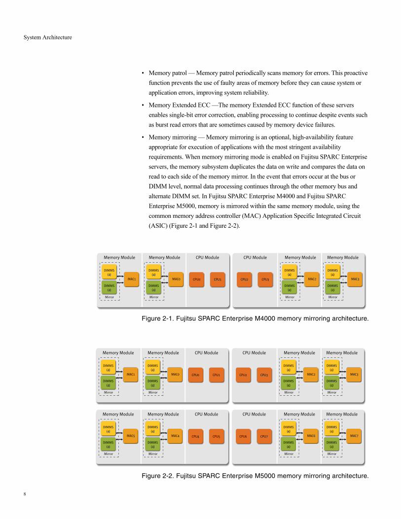
• Memory mirroring — Memory mirroring is an optional, high-availability feature appropriate for execution of applications with the most stringent availability requirements. When memory mirroring mode is enabled on Fujitsu SPARC Enterprise servers, the memory subsystem duplicates the data on write and compares the data on read to each side of the memory mirror. In the event that errors occur at the bus or DIMM level, normal data processing continues through the other memory bus and alternate DIMM set. In Fujitsu SPARC Enterprise M4000 and Fujitsu SPARC Enterprise M5000, memory is mirrored within the same memory module, using the common memory address controller (MAC) Application Specific Integrated Circuit (ASIC) (Figure 2-1 and Figure 2-2).
Figure 2-1. Fujitsu SPARC Enterprise M4000 memory mirroring architecture.
Figure 2-2. Fujitsu SPARC Enterprise M5000 memory mirroring architecture.
Memory Module
Mirror
DIMMS(4)
DIMMS(4)
MAC1
Mirror
DIMMS(4)
DIMMS(4)
MAC0
Memory Module
CPU0
CPU Module
CPU1
Memory Module
Mirror
DIMMS(4)
DIMMS(4)
MAC3
Mirror
DIMMS(4)
DIMMS(4)
MAC2
Memory Module
CPU2
CPU Module
CPU3
Memory Module
Mirror
DIMMS(4)
DIMMS(4)
MAC1
Mirror
DIMMS(4)
DIMMS(4)
MAC0
Memory Module
CPU0
CPU Module
CPU1
Memory Module
Mirror
DIMMS(4)
DIMMS(4)
MAC3
Mirror
DIMMS(4)
DIMMS(4)
MAC2
Memory Module
CPU2
CPU Module
CPU3
Memory Module
Mirror
DIMMS(4)
DIMMS(4)
MAC5
Mirror
DIMMS(4)
DIMMS(4)
MAC4
Memory Module
CPU4
CPU Module
CPU5
Memory Module
Mirror
DIMMS(4)
DIMMS(4)
MAC7
Mirror
DIMMS(4)
DIMMS(4)
MAC6
Memory Module
CPU6
CPU Module
CPU7
8

System Architecture
On Fujitsu SPARC Enterprise M8000 and Fujitsu SPARC Enterprise M9000, memory is mirrored across adjacent MAC ASICs to increase reliability (Figure 2-7). However, in a Quad-XSB configuration, paired DIMMs are split across different Fujitsu SPARC Enterprise M8000 and Fujitsu SPARC Enterprise M9000 Quad-XSBs. As such, memory mirroring is incompatible with the optional configuration of Quad-XSBs on Fujitsu SPARC Enterprise high-end server system boards.
Figure 2-3. Fujitsu SPARC Enterprise M8000 and Fujitsu SPARC Enterprise M9000 memory mirroring architecture.
Mirror
4DIMMS
4DIMMS
MAC1
MAC0CPU0
CPU1
MAC3
MAC2CPU2
CPU3
Mirror
Mirror
Mirror
SC0
SC1
SC2
SC3
4DIMMS
4DIMMS
4DIMMS
4DIMMS
= Group A
= Group B
4DIMMS
4DIMMS
9

System Architecture
2.1.4 System ClockWhile the implementation of the system clock varies within each member of the Fujitsu SPARC Enterprise server family, all are engineered with reliability in mind. In particular, Fujitsu SPARC Enterprise M8000 and Fujitsu SPARC Enterprise M9000 use a clock chip with redundant internal components. These high-end servers also implement two sources of clock signal and a dual signal source synchronous line exists between the clock chip and the system boards, enabling the system to restart in the event one route fails. Further enhancing availability and easing maintenance, the Fujitsu SPARC Enterprise M9000 provides for configuration of a redundant clock control unit.
2.1.5 PCI-Express and PCI-eXtended TechnologyFujitsu SPARC Enterprise servers use a PCI bus to provide high-speed data transfer within the I/O subsystem. In order to support PCIe expansion cards, all Fujitsu SPARC Enterprise servers use a PCIe physical layer (PCIe PHY) ASIC to manage the implementation of the PCIe protocol. PCIe technology doubles the peak data transfer rates of original PCI technology and reaches 2.5 Gb/second of throughput. In fact, PCIe was developed to accommodate high-speed interconnects such as Fibre Channel, Infiniband, and Gigabit Ethernet. Fujitsu SPARC Enterprise servers also support PCI-X expansion cards for fast access to external devices. PCI-X is backward compatible with existing PCI cards, but increases bandwidth enabling data transfer of up to 1 GB/second for 64-bit devices. Additional technical details for Fujitsu SPARC Enterprise server I/O subsystems can be found in Chapter 5 – I/O Subsystem.
2.1.6 Service Processor – Extended System Control FacilitySimplifying management of compute systems leads to higher availability levels for hosted applications. With this in mind, mid-range and high-end models of Fujitsu SPARC Enterprise servers include an eXtended System Control Facility (XSCF). The XSCF consists of a dedicated processor that is independent of the server and runs the XSCF Control Package (XCP) to provide remote monitoring and management capabilities. This service processor regularly monitors environmental sensors, provides advanced warning of potential error conditions, and executes proactive system maintenance procedures as necessary. Indeed, while power is supplied to the server, the XSCF constantly monitors the platform even if the system is inactive. XCP enables Dynamic Domains (= partitioning feature) configuration, audit administration, hardware control capabilities, hardware status monitoring, reporting, and handling, automatic diagnosis and domain recovery, capacity on demand operations, and XSCF failover services. Additional technical details about the XSCF and XCP are found in Chapter 7 – System Management.
10
System Architecture
2.1.7 Power and CoolingFujitsu SPARC Enterprise servers use separate modules for power and cooling. Sensors placed throughout the system measure temperatures on processors and key ASICS as well as the ambient temperature at several location. Hardware redundancy in the power and cooling subsystems combined with environmental monitoring keep servers operating even under power or fan fault conditions.
2.1.7.1 Fan Unit
Fujitsu SPARC Enterprise server family members use fully redundant, hot-swap fans as the primary cooling system (Table 2-2 and Table 2-3). If a single fans fails, the XSCF detects the failure and switches the remaining fans to high-speed operation to compensate for the reduced airflow. Fujitsu SPARC Enterprise servers operate normally under these conditions, enabling ample time to service the failed unit. Replacement of fans units can occur without interrupting application processing.
2.1.7.2 Power Supply
The use of redundant power supplies and power cords adds to the fault resilience of Fujitsu SPARC Enterprise servers (Table 2-2 and Table 2-3). Power is supplied to Fujitsu SPARC Enterprise servers by redundant hot-swap power supplies, enabling continued server operation even if a power supply fails. Since the power units are hot-swappable, removal and replacement can occur while the system continues to operate.
As an option, Fujitsu SPARC Enterprise M8000 and Fujitsu SPARC Enterprise M9000 can be ordered with a three-phase power supply unit and corresponding server cabinet. Models with a three-phase power supply permit two configurations, a star connection that connects a neutral line and each phase, and a delta connection that connects each phase.
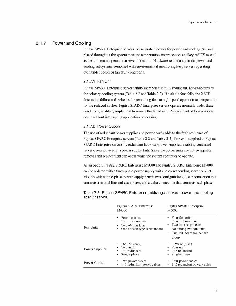
Table 2-2. Fujitsu SPARC Enterprise midrange servers power and cooling specifications.
Fujitsu SPARC Enterprise M4000
Fujitsu SPARC Enterprise M5000
Fan Units
• Four fan units• Two 172 mm fans • Two 60 mm fans• One of each type is redundant
• Four fan units• Four 172 mm fans • Two fan groups, each
containing two fan units• One redundant fan per fan
group
Power Supplies• 1656 W (max)• Two units• 1+1 redundant• Single-phase
• 3198 W (max)• Four units• 2+2 redundant• Single-phase
Power Cords • Two power cables• 1+1 redundant power cables
• Four power cables• 2+2 redundant power cables
11

System Architecture
Table 2-3. Fujitsu SPARC Enterprise high-end servers power and cooling specifications.
2.1.7.3 Optional Dual Power Feed
While enterprises can control most factors within the datacenter, utility outages are often unexpected. The consequences of loss of electrical power can be devastating to IT operations. In order to enable organizations to reduce the impact of such incidents, mid-range and high-end models of Fujitsu SPARC Enterprise servers are dual power feed capable. The AC power subsystem in these servers is completely duplicated, enabling optional reception of power from two external, independent AC power sources. The use of a dual power feed and redundant power supplies increases system availability, as server operations can remain unaffected even after a single power grid failure.
2.1.8 Operator PanelMid-range and high-end models of Fujitsu SPARC Enterprise servers feature an operator panel to display server status, store server identification and user setting information, change between operational and maintenance modes, and turn on power supplies for all domains. During server startup, the front panel LED status indicators verify XSCF and server operation.
Figure 2-4. The Fujitsu SPARC Enterprise server operator panel.
Fujitsu SPARC Enterprise M8000
Fujitsu SPARC Enterprise M9000(32 CPU configuration)
Fujitsu SPARC Enterprise M9000 (64 CPU configuration)
Fan Units• 12 fan units• Four 172 mm fans • Eight 60 mm fans• N+1 redundant
• 16 fan units• 16 172 mm fans• N+1 redundant
• 32 fan units• 32 172 mm fans • N+1 redundant
Power Supplies• 10.49 kW (max)• 9 units• N+1 redundant
• 19.87 kW (max)• 15 units• N+1 redundant
• 39.72 kW (max)• 30 units• N+1 redundant
Options• Single-phase• Three-phase• Dual-grid
• Single-phase• Three-phase• Dual-grid
• Single-phase• Three-phase• Dual-grid
Power Cords
• 3 power cables (single feed)
• 6 power cables (dual feed)
• 2 power cables (three-phase)
• 5 power cables (single feed)
• 10 power cables (dual feed)
• 2 power cables (three-phase)
• 10 power cables (single feed)
• 20 power cables (dual feed)
• 4 power cables (three-phase)
Locked
Service
Mode switchPOWER switchCHECK (LED)STANDBY (LED)
POWER (LED)
12

System Architecture
2.2 Midrange Systems — Fujitsu SPARC Enterprise M4000 and Fujitsu SPARC Enterprise M5000
Fujitsu SPARC Enterprise M4000 and Fujitsu SPARC Enterprise M5000 are economical, high-power compute platforms with enterprise-class features. These midrange servers are designed to reliably carry datacenter workloads that support core business operations.
2.2.1 Fujitsu SPARC Enterprise M4000The Fujitsu SPARC Enterprise M4000 enclosure measures six rack-units (RU) and supports up to four processor chips, 128 GB of memory, and up to two Dynamic Domains. As a processor chip, either SPARC64 VI or SPARC64 VII can be mounted, or both can be mounted together. In addition, the Fujitsu SPARC Enterprise M4000 features four short internal PCIe slots and one short internal PCI-X slot, as well as two disk drives, one DVD drive, and an optional DAT tape drive. Two power supplies and four fan units power and cool the Fujitsu SPARC Enterprise M4000.
Figure 2-5. Fujitsu SPARC Enterprise M4000 enclosure diagram.
PCI Slots XSCF Unit
Fan Units
DVD Drive Unit
DiskDrives
Tape Drive Unit
CPU
Memory
Power Supply Units
Front Back
13
System Architecture
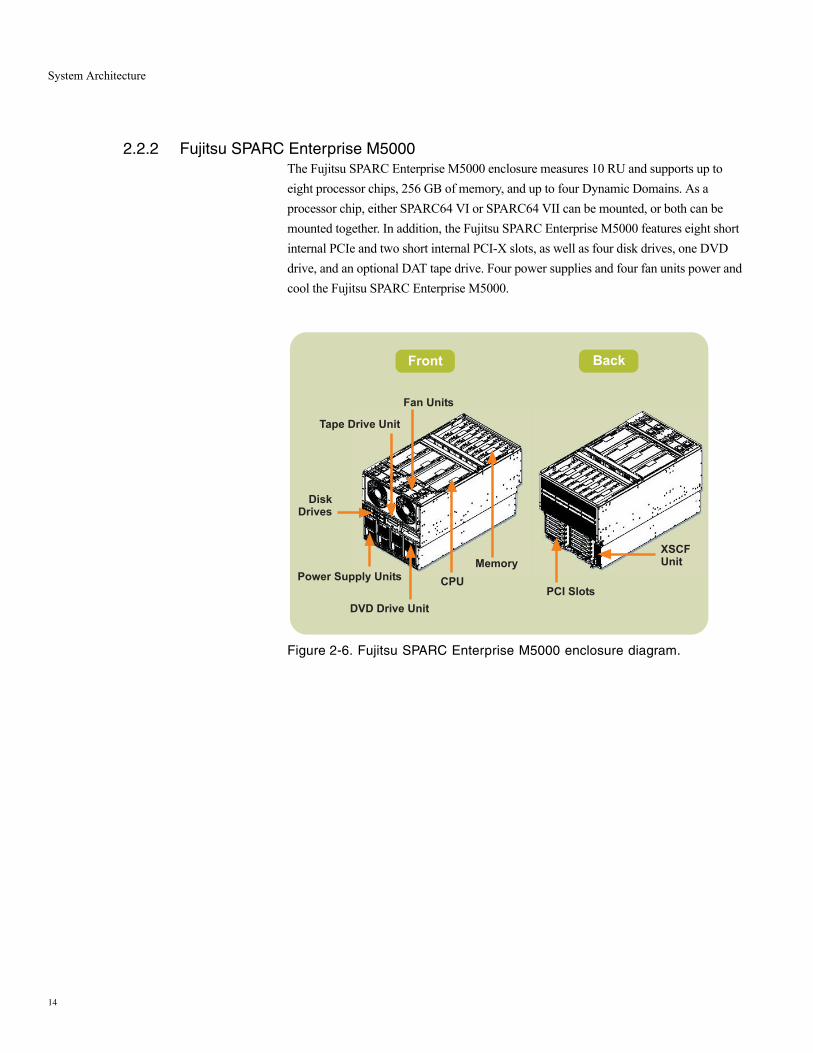
2.2.2 Fujitsu SPARC Enterprise M5000The Fujitsu SPARC Enterprise M5000 enclosure measures 10 RU and supports up to eight processor chips, 256 GB of memory, and up to four Dynamic Domains. As a processor chip, either SPARC64 VI or SPARC64 VII can be mounted, or both can be mounted together. In addition, the Fujitsu SPARC Enterprise M5000 features eight short internal PCIe and two short internal PCI-X slots, as well as four disk drives, one DVD drive, and an optional DAT tape drive. Four power supplies and four fan units power and cool the Fujitsu SPARC Enterprise M5000.
Figure 2-6. Fujitsu SPARC Enterprise M5000 enclosure diagram.
Front Back
PCI Slots
XSCFUnit
Fan Units
DVD Drive Unit
DiskDrives
Tape Drive Unit
CPU
Memory
Power Supply Units
14
System Architecture
2.3 High-End Systems — Fujitsu SPARC Enterprise M8000 and Fujitsu SPARC Enterprise M9000
Designed to deliver outstanding performance for even the most challenging workloads, high-end Fujitsu SPARC Enterprise servers merge mainframe reliability, advanced performance technology often used in supercomputers, and an open systems environment to create reliable, high-throughput, flexible systems.
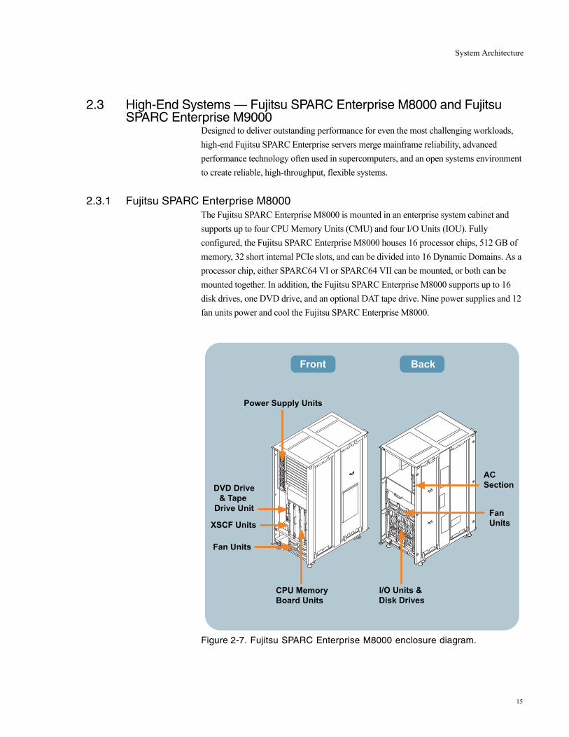
2.3.1 Fujitsu SPARC Enterprise M8000The Fujitsu SPARC Enterprise M8000 is mounted in an enterprise system cabinet and supports up to four CPU Memory Units (CMU) and four I/O Units (IOU). Fully configured, the Fujitsu SPARC Enterprise M8000 houses 16 processor chips, 512 GB of memory, 32 short internal PCIe slots, and can be divided into 16 Dynamic Domains. As a processor chip, either SPARC64 VI or SPARC64 VII can be mounted, or both can be mounted together. In addition, the Fujitsu SPARC Enterprise M8000 supports up to 16 disk drives, one DVD drive, and an optional DAT tape drive. Nine power supplies and 12 fan units power and cool the Fujitsu SPARC Enterprise M8000.
Figure 2-7. Fujitsu SPARC Enterprise M8000 enclosure diagram.
Front Back
Power Supply Units
CPU Memory Board Units
Fan Units
XSCF Units
DVD Drive& Tape
Drive Unit
AC Section
Fan Units
I/O Units & Disk Drives
15
System Architecture
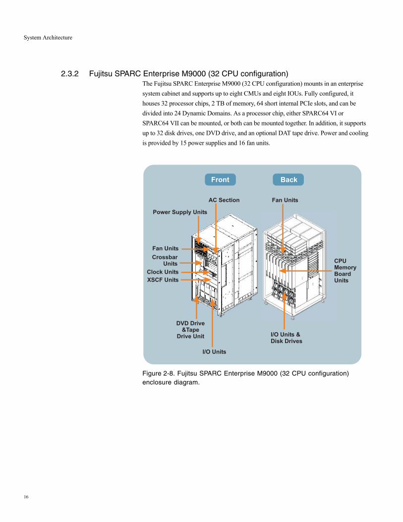
2.3.2 Fujitsu SPARC Enterprise M9000 (32 CPU configuration)The Fujitsu SPARC Enterprise M9000 (32 CPU configuration) mounts in an enterprise system cabinet and supports up to eight CMUs and eight IOUs. Fully configured, it houses 32 processor chips, 2 TB of memory, 64 short internal PCIe slots, and can be divided into 24 Dynamic Domains. As a processor chip, either SPARC64 VI or SPARC64 VII can be mounted, or both can be mounted together. In addition, it supports up to 32 disk drives, one DVD drive, and an optional DAT tape drive. Power and cooling is provided by 15 power supplies and 16 fan units.
Figure 2-8. Fujitsu SPARC Enterprise M9000 (32 CPU configuration) enclosure diagram.
Front Back
CPUMemoryBoardUnits
I/O Units &Disk Drives
Fan Units
Fan UnitsAC Section
DVD Drive&Tape
Drive Unit
XSCF Units
Power Supply Units
I/O Units
Clock Units
CrossbarUnits
16

System Architecture
2.3.3 Fujitsu SPARC Enterprise M9000 (64 CPU configuration)An expansion cabinet can be added to an existing base cabinet to create the Fujitsu SPARC Enterprise M9000 (64 CPU configuration) which supports up to 16 CMUs and 16 IOUs. Fully configured, it houses 64 processor chips, 4 TB of memory, 128 short internal PCIe slots, and can be divided into 24 Dynamic Domains. As a processor chip, either SPARC64 VI or SPARC64 VII can be mounted, or both can be mounted together. In addition, it supports up to 64 disk drives, two DVD drives, and two optional DAT tape drives. The Fujitsu SPARC Enterprise M9000 (64 CPU configuration) utilizes 30 power supplies and 32 fan units for power and cooling.
Figure 2-9. Fujitsu SPARC Enterprise M9000 (64 CPU configuration) enclosure diagram.
ExpansionCabinet
BaseCabinet
Rack forI/O Expansion
17
System Bus Architecture — Jupiter Interconnect
3. System Bus Architecture — Jupiter Intercon-nect
High end systems containing dozens of CPUs only provide scalability if all processors actually contribute to the performance of the application. The ability to deliver near-linear scalability and fast, predictable performance for a broad set of applications rests largely on the capabilities of the system bus. Fujitsu SPARC Enterprise servers utilize a system interconnect designed to deliver massive bandwidth and consistent, low latency between components. The Jupiter system bus benefits IT operations by delivering balanced and predictable performance to application workloads.
3.1 Fujitsu SPARC Enterprise Server Interconnect ArchitectureThe Jupiter interconnect design maximizes the overall performance of Fujitsu SPARC Enterprise servers. Implemented as point-to-point connections which utilize packet-switched technology, this system bus provides fast response times by transmitting multiple data streams. Packet-switching enables the interconnect to operate at much higher system-wide throughput by eliminating “dead” cycles on the bus. All routes are uni-directional, non-contentious paths with multiplexed address, data, and control plus ECC in each direction.
System controllers within the interconnect architecture on all Fujitsu SPARC Enterprise servers direct traffic between local CPUs, memory, I/O subsystems, and interconnect paths. On high-end systems, the system bus is implemented as a crossbar switch between system boards to support high-throughput data transfer with consistent latency times between all components. In addition, the physical addressing of memory on a motherboard of a Fujitsu SPARC Enterprise midrange server or CMU of a Fujitsu SPARC Enterprise high-end server is evenly spread out across all system controllers on that same board, improving performance.
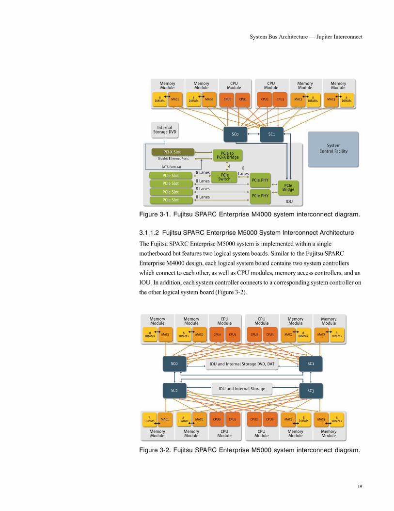
3.1.1.1 Fujitsu SPARC Enterprise M4000 System Interconnect Architecture
The Fujitsu SPARC Enterprise M4000 system is implemented within a single motherboard. This server design features one logical system board with two system controllers. Both system controllers connect to each other, as well as CPU modules, memory address controllers, and the IOU (Figure 3-1).
18
System Bus Architecture — Jupiter Interconnect
Figure 3-1. Fujitsu SPARC Enterprise M4000 system interconnect diagram.
3.1.1.2 Fujitsu SPARC Enterprise M5000 System Interconnect Architecture
The Fujitsu SPARC Enterprise M5000 system is implemented within a single motherboard but features two logical system boards. Similar to the Fujitsu SPARC Enterprise M4000 design, each logical system board contains two system controllers which connect to each other, as well as CPU modules, memory access controllers, and an IOU. In addition, each system controller connects to a corresponding system controller on the other logical system board (Figure 3-2).
Figure 3-2. Fujitsu SPARC Enterprise M5000 system interconnect diagram.
Gigabit Ethernet Ports
4
PCIe to PCI-X Bridge
PCI-X Slot
IOU
PCIeBridge
PCIe PHY
PCIe PHY
PCIeSwitch
8LanesPCIe Slot
PCIe Slot
PCIe Slot
PCIe Slot
8 Lanes
8 Lanes
8 Lanes
8 Lanes
CPUModule
Internal Storage DVD SC1SC0
SystemControl Facility
SATA Ports (4)
8DIMMs MAC1 8
DIMMs MAC0 CPU0 CPU1 CPU2 CPU3 MAC2
MemoryModule
MAC3 8DIMMs
8DIMMs
MemoryModule
CPUModule
MemoryModule
MemoryModule
CPUModule
SC1SC0
8DIMMs MAC1 8
DIMMs MAC0 CPU0 CPU1 CPU2 CPU3 MAC2
MemoryModule
MAC3 8DIMMs
8DIMMs
MemoryModule
CPUModule
MemoryModule
MemoryModule
CPUModule
8DIMMs MAC1 8
DIMMs MAC0 CPU0 CPU1 CPU2 CPU3 MAC2
MemoryModule
MAC3 8DIMMs
8DIMMs
MemoryModule
CPUModule
MemoryModule
MemoryModule
SC2 SC3
IOU and Internal Storage DVD, DAT
IOU and Internal Storage
19

System Bus Architecture — Jupiter Interconnect
3.1.1.3 Fujitsu SPARC Enterprise M8000 and Fujitsu SPARC Enterprise
M9000 System Interconnect Architecture
Fujitsu SPARC Enterprise M8000 and Fujitsu SPARC Enterprise M9000 feature multiple system boards which connect to a common crossbar. Each system board contains four system controllers. Each system controller connects to every CPU module. For improved bandwidth, every memory access controller connects to two system controllers, and each system controller connects to every other system controller within the system board. The system controllers also provide a connection to each crossbar unit, enabling data transfer to other system boards (Figure 3-3).
Figure 3-3. Fujitsu SPARC Enterprise M8000 and Fujitsu SPARC Enterprise M9000 system interconnect diagram.
CPU
Memory Controller
CPU
Memory Controller
CPU
Memory Controller
CPU
Memory Controller
DDR2 DIMMS (8)
DDR2 DIMMS (8)
DDR2 DIMMS (8)
DDR2 DIMMS (8)
SystemController
SystemController
SystemController
SystemController
PCIe Slot
PCIe Slot
PCIe Slot
PCIe Slot
PCIe Slot
PCIe Slot
PCIe Slot
PCIe Slot
PCIe PHY
PCIe PHY
PCIe PHY
PCIe PHY
8x8 Crossbar
8x8 Crossbar
8x8 Crossbar
8x8 Crossbar
8 Lanes
8 Lanes
8 Lanes
8 Lanes
8 Lanes
8 Lanes
8 Lanes
8 Lanes
System Board
I/O Board
XB Board
PCIeBridge
(8)
PCIeBridge
(8)
20

System Bus Architecture — Jupiter Interconnect
3.2 System Interconnect Reliability FeaturesBuilt-in redundancy and reliability features of Fujitsu SPARC Enterprise server system interconnects enhance the stability of these servers. The Jupiter interconnect protects against loss or corruption of data with full ECC protection on all system buses and in memory. When a single-bit data error is detected in a CPU, Memory Access Controller, or I/O Controller, hardware corrects the data and performs the transfer. Fujitsu SPARC Enterprise M8000 and Fujitsu SPARC Enterprise M9000 feature degradable crossbar switches and degradable bus routes. In the rare event of a hardware failure within the interconnect, the system uses the surviving bus route on restart, isolating the faulty crossbar and enabling operations to resume.
21
System Bus Architecture — Jupiter Interconnect
3.3 Scalable PerformanceThe high bandwidth and overall design of the Jupiter system interconnect contributes to the scalable performance of Fujitsu SPARC Enterprise servers. Theoretical peak system throughput, snoop bandwidth, and I/O Bandwidth numbers, as well as Stream benchmark results for all Fujitsu SPARC Enterprise servers are found in Table 3-1.
In Fujitsu SPARC Enterprise servers, the CPUs, memory address controllers, and IOUs are directly connected by a high-speed broadband switch for data transfer, enabling a relatively even latency to be maintained between individual components. As components are added, processing capability and latency are not degraded. In fact, the crossbar interconnect implementation in Fujitsu SPARC Enterprise high-end servers results in increased interconnect bandwidth every time a system board is added to the server.
22

System Bus Architecture — Jupiter Interconnect
Table 3-1. Theoretical system bandwidth and theoretical I/O bandwidth at peak time, snoop bandwidth, and stream benchmark results for SPARC Enterprise.
Theoretical system bandwidth at peak timea (GB/s)
a.The theoretical system bandwidth at peak time is calculated by multiplying the bus width by the bus frequency between the system controller and memory access controller.
Snoop bandwidth (GB/s)
Triad results of stream benchmark (GB/s)
Copy results of stream benchmark (GB/s)
Theoretical I/O bandwidth at peak timeb (GB/s)
b.The logical I/O bandwidth at peak time is calculated by multiplying the bus width by the bus frequency between the system controller and PCI bridge.
SPARC Enterprise M4000 32 129 12.7 12.6 8
SPARC Enterprise M5000 64 129 25.3 24.8 16
SPARC Enterprise M8000 184 245 69.6 60.3 61
SPARC Enterprise M9000 (32-CPU configuration)
368 245 134.4 114.9 122
SPARC Enterprise M9000 (64-CPU configuration)
737 245 227.1 224.4 244
23

Fujitsu SPARC64 VI/SPARC64 VII Processors
4. Fujitsu SPARC64 VI/SPARC64 VII Proces-sors
4.1 SPARC64 SeriesThe SPARC64 Series is a SPARC processor developed by Fujitsu for UNIX servers. High reliability technology of the mainframe class and a frequency exceeding 1 GHz have been realized with the SPARC64 V. This processor has been used for Fujitsu PRIMEPOWER servers. The SPARC64 VI has realized high throughput by using the SPARC64 V as a base and by incorporating a two-core x two thread architecture. The throughput of the latest SPARC 64 VII has been improved further by incorporating four-core architecture and by modifying the multi-threading mechanism. These SPARC64 VI and SPARC64 VII processors are used with SPARC Enterprise servers.
24
Fujitsu SPARC64 VI/SPARC64 VII Processors
4.2 SPARC64 VI OverviewThe SPARC64 VI is a SPARC64 series processor developed by Fujitsu using its 90-nm technology. This processor has an operating frequency of 2.4 GHz, and a chip size of 20.4 x 10.7 mm. The chip, which has two built-in cores and a shared 6-MB L2 cache, has a maximum operating power consumption of 120 W.
The SPARC64 VI design not only retains the high performance and high reliability of the SPARC64 V, but also features throughput improved considerably with the use of two CPU cores packed in one chip and Vertical Multi Threading, which is being adopted for the first time in the SPARC64 series. Furthermore, the new system bus called Jupiter bus has been designed to maximize the performance of SPARC64 VI and SPARC64 VII.
25
Fujitsu SPARC64 VI/SPARC64 VII Processors
4.3 SPARC64 VII OverviewThe SPARC64 VII is the latest processor developed by Fujitsu for the SPARC64 Series. It uses the 65-nm technology of Fujitsu and it has realizes an operating frequency of 2.88 GHz. The chip measures 21.3 mm by 20.9 mm. The chip has four built-in cores with a shared 6 MB L2 cache configuration. The operating power consumption is 140 W.
Fujitsu designed the SPARC64 VII for increased throughput while maintaining the high performance and high reliability that have been realized with the existing SPARC64 VI. For increased throughput, the number of built-in cores has been increased from two to four, and the multi-threading mechanism to be used has been changed from VMT to SMT. The L2 cache is configured to be shared by the four cores, and the throughput has been doubled so that data can be supplied to the four cores. Also, especially with the field of high performance computing (HPC) in mind, an inter-core high-speed synchronization mechanism called hardware barrier has been implemented.
At the same time, by using a bus protocol that is the same as that of the existing SPARC64 VI, each CPU module can be upgraded from SPARC64 VI to SPARC64 VII.
26
Fujitsu SPARC64 VI/SPARC64 VII Processors
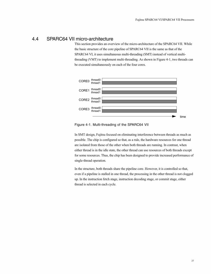
4.4 SPARC64 VII micro-architectureThis section provides an overview of the micro-architecture of the SPARC64 VII. While the basic structure of the core pipeline of SPARC64 VII is the same as that of the SPARC64 VI, it uses simultaneous multi-threading (SMT) instead of vertical multi-threading (VMT) to implement multi-threading. As shown in Figure 4-1, two threads can be executed simultaneously on each of the four cores.
Figure 4-1. Multi-threading of the SPARC64 VII
In SMT design, Fujitsu focused on eliminating interference between threads as much as possible. The chip is configured so that, as a rule, the hardware resources for one thread are isolated from those of the other when both threads are running. In contrast, when either thread is in the idle state, the other thread can use resources of both threads except for some resources. Thus, the chip has been designed to provide increased performance of single-thread operation.
In the structure, both threads share the pipeline core. However, it is controlled so that, even if a pipeline is stalled in one thread, the processing in the other thread is not clogged up. In the instruction fetch stage, instruction decoding stage, or commit stage, either thread is selected in each cycle.
time
CORE0 thread0thread1
thread0thread1
thread0thread1
thread0thread1
CORE1
CORE2
CORE3
27

Fujitsu SPARC64 VI/SPARC64 VII Processors
4.4.1 Details of the Micro-architectureDetails of the micro-architecture are outlined below.
As shown in Figure 4-2, a core of the SPARC64 VII is divided into the instruction fetch block and instruction execution block. The instruction fetch block includes the primary cache dedicated for instructions (L1I cache), and the instruction execution block includes the primary cache dedicated for operands (L1D cache).
Figure 4-2. Functional diagram of the SPARC64 VII core
4.4.2 Instruction Fetch blockThe instruction fetch block, which operates independently of the instruction execution block, takes a series of instructions into the instruction buffer (IBUF), which are expected to be executed according to branch prediction. The IBUF has a capacity of 256 bytes, and can store up to 64 instructions. When both threads are running, the IBUF is divided evenly for each thread.
When the instruction execution is stalled, instruction fetch continues until the IBUF becomes full. In contrast, when instruction fetch pauses for some reason such as a cache error, instructions can be taken from the IBUF and execution can continue as long as the IBUF includes instructions. Instruction fetch can be started in every cycle, and 32 bytes, which comprise eight instructions, are fetched at one time. The throughput of instruction execution is up to four instructions per cycle, while twice the throughput of instruction execution is assured for instruction fetch. The IBUF conceals the latency of the large-capacity primary instruction cache by separating instruction fetch and instruction execution from each other (decoupling).
IWRL1I$ IBUF
分岐予測
RSA
RSBR
RSF
RSE
L1D$FP
SP
命令フェッチ部 命令実行部
AGEN
FL
EX
Instruction fetch block Instruction execution block
Branch prediction
28
Fujitsu SPARC64 VI/SPARC64 VII Processors
4.4.3 Instruction Execution Block
4.4.3.1 Instruction decode and issue
In the Instruction decode and instruction issue stages, the four instructions in the IWR are decoded simultaneously, and resources required for execution (various reservation stations, fetch port and store port, and register update buffer) are determined. Then, whether there are free resources for them is checked. If there are free resources, they are allocated and given instruction identifications (IID) ranging from 0 to 63. Then, the instruction is issued. In other words, the maximum number of in-flight instructions is 64. Meanwhile, when both threads are running, the maximum number of instructions for each thread is 32. In each cycle, an instruction of either thread is decoded and threads are alternately switched.
When an instruction is issued, the IWR is released. For the instruction in any slot of the IWR, there are no restrictions on the allocation of resources such as reservation stations. Also, there are no restrictions on instruction type combinations. Therefore, as long as there are free resources, instructions can be issued. Even if there is no sufficient space for four instructions, as many instructions as possible are issued in program order. As described above, by eliminating stall conditions of instruction issue as much as possible, a high multiplicity level is assured for any binary code.
4.4.3.2 Instruction execution
A decoded instruction is registered in a reservation station. The SPARC64 VII has reservation stations for integer operation (reservation stations for execution: RSE) and reservation stations for floating point operation (reservation stations for floating point: RSF). The RSEs and RSFs are divided into two queues for the execution unit. In other words, four reservation stations for operation are provided. They are RSEA, RSEB, RSFA, and RSFB. Each instruction stored in a reservation station is dispatched to the execution unit that corresponds to the reservation station in the order in which source operands are prepared for instructions. Therefore, four operations can be dispatched simultaneously. Basically, the oldest instruction that can be dispatched (oldest ready) is selected from the instructions in a reservation station. However, in cases where a register to be updated by a load instruction is used as a source operand for an operation, the instruction is speculatively dispatched before the result of the load instruction is obtained. Then, in the execution stage, whether the speculative dispatch has been successful is determined. This is called speculative dispatch. Use of speculative dispatch conceals the latency of the pipeline for cache access, increasing the use efficiency of the execution unit.
In addition to the above described RSEs and RSFs, there are other reservation stations, which are reservation stations for branch instructions (reservation station for branch: RSBR) and reservation stations for calculating addresses for load/store instructions (reservation station for address generation: RSA).
29

Fujitsu SPARC64 VI/SPARC64 VII Processors
4.4.3.3 Instruction commit
All results of instructions that are executed out of order are once stored in the GUB and FUB work registers, which not visible to software. To assure the instruction order in a program, registers such as GPR and FPR and memory are updated in program order in the commit stage. In addition, control registers such as the PC are also updated at the same time in the commit stage. As described above, precise interrupt is guaranteed, and processing in execution can always be canceled. The method above is called a synchronous update method, which does not only make it easier to re-execute instructions due to a branch prediction error, but also contributes to increased RAS as explained in a later chapter. The maximum number of instructions that can be committed at one time is four. The instruction commit stage is shared by the two threads, and either thread is selected in each cycle to perform commit processing.
30
Fujitsu SPARC64 VI/SPARC64 VII Processors
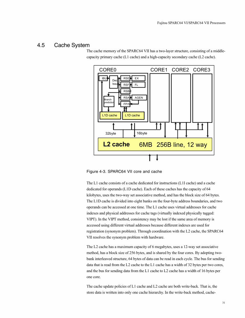
4.5 Cache SystemThe cache memory of the SPARC64 VII has a two-layer structure, consisting of a middle-capacity primary cache (L1 cache) and a high-capacity secondary cache (L2 cache).
Figure 4-3. SPARC64 VII core and cache
The L1 cache consists of a cache dedicated for instructions (L1I cache) and a cache dedicated for operands (L1D cache). Each of these caches has the capacity of 64 kilobytes, uses the two-way set associative method, and has the block size of 64 bytes. The L1D cache is divided into eight banks on the four-byte address boundaries, and two operands can be accessed at one time. The L1 cache uses virtual addresses for cache indexes and physical addresses for cache tags (virtually indexed physically tagged: VIPT). In the VIPT method, consistency may be lost if the same area of memory is accessed using different virtual addresses because different indexes are used for registration (synonym problem). Through coordination with the L2 cache, the SPARC64 VII resolves the synonym problem with hardware.
The L2 cache has a maximum capacity of 6 megabytes, uses a 12-way set associative method, has a block size of 256 bytes, and is shared by the four cores. By adopting two-bank interleaved structure, 64 bytes of data can be read in each cycle. The bus for sending data that is read from the L2 cache to the L1 cache has a width of 32 bytes per two cores, and the bus for sending data from the L1 cache to L2 cache has a width of 16 bytes per one core.
The cache update policies of L1 cache and L2 cache are both write-back. That is, the store data is written into only one cache hierarchy. In the write-back method, cache-
L1Dキャッシュ
IBUFDecIssue
RSA
RSE
RSF
RSBR
FP/SP
EX
FL
AGEN
L1Iキャッシュ
分岐予測
L2キャッシュ 6MB 256B line, 12 way
16byte32byte
CORE0 CORE1 CORE2 CORE3
Branch prediction
L1D cache L1D cache
L2 cache
31

Fujitsu SPARC64 VI/SPARC64 VII Processors
missed lines are always loaded on to the cache memory, so that the store operations can complete with updating one cache hierarchy. In the write-back method, it is necessary to bring old data on the memory onto the cache, even if the data is stored, when a cache error occurs, but store operation is completed only on the cache when a cache hit occurs. In general, because the frequency of the store operation is quite high, the write-back method has an advantage because it can reduce intercache traffic and memory access traffic.
Meanwhile, because the write-back method keeps the latest data in the cache, if an error occurs in the relevant processor, there is a risk that the error may affect not only the internal operation of the processor, but also the entire system. The SPARC64 VII has powerful RAS functions to cope with this problem.
Also, a new hardware barrier mechanism has been implemented in the SPARC64 VII. The hardware barrier mechanism synchronizes the cores in a CPU chip with each other, and faster synchronization processing can be implemented compared with a conventional synchronization process realized by software. This mechanism is especially useful in the HPC area.
32

Fujitsu SPARC64 VI/SPARC64 VII Processors
4.6 Reliability, Availability, and Serviceability (RAS) FunctionsIn the SPARC64 VII, RAS functions comparable to mainframe computers have been implemented. With these RAS functions, errors are reliably detected, their effect is kept within a limited range, recovery processing is tried, error logs are recorded, software is notified, and so forth. In other words, the basics of RAS functions are thoroughly implemented. Through the implementation of the RAS functions, the SPARC64 VII provides high reliability, high availability, high serviceability, and high data integrity as a processor for mission-critical UNIX servers.
4.6.1 RAS of Internal RAMsAmong the parts of a processor, the error occurrence frequency is highest in RAM. In the SPARC64 VII, because any one-bit error in RAM can automatically be corrected by hardware without intervention by software, it does not affect software.
SECDED: Single Error Correction Double Error Detection
For the L1 cache, L2 cache, and TLB, degradation can be performed separately in way units. Error occurrence counts are counted for each function unit. When an error occurrence count per unit time exceeds the upper limit, degradation is performed and the relevant way is not used subsequently. Hardware performs degradation automatically. At the same time, it also performs the required operation to assure the continuity of coherency automatically. More specifically, hardware automatically performs the following: 1) operation that writes back to the L2 cache all the dirty lines in the way of the L1D cache to be degraded, and 2) operation that writes back to the memory the dirty lines in the way of the L2 cache to be degraded. The degradation of a way is performed without adversely affecting software, and software operation is free from any effects except for a slowdown of processing speed.
Type Error detection method Protection method
Error correction method
L1 instruction cache Data Parity Invalidation and reread
Tag Parity + duplication Rewrite of duplicated data
L1 data cache Data SECDED ECC One-bit error correction using ECC
Tag Parity + duplication Rewrite of duplicated data
L2 cache Data SECDED ECC One-bit error correction using ECC
Tag SECDED ECC One-bit error correction using ECC
Instruction TLB Parity Invalidation
Data TLB Parity Invalidation
Branch history Parity Recovery from branch prediction failure
33
Fujitsu SPARC64 VI/SPARC64 VII Processors
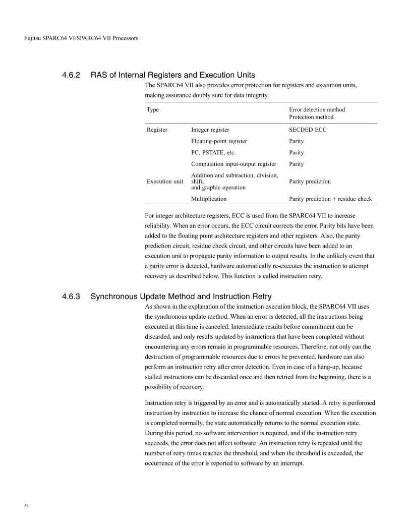
4.6.2 RAS of Internal Registers and Execution UnitsThe SPARC64 VII also provides error protection for registers and execution units, making assurance doubly sure for data integrity.
For integer architecture registers, ECC is used from the SPARC64 VII to increase reliability. When an error occurs, the ECC circuit corrects the error. Parity bits have been added to the floating point architecture registers and other registers. Also, the parity prediction circuit, residue check circuit, and other circuits have been added to an execution unit to propagate parity information to output results. In the unlikely event that a parity error is detected, hardware automatically re-executes the instruction to attempt recovery as described below. This function is called instruction retry.
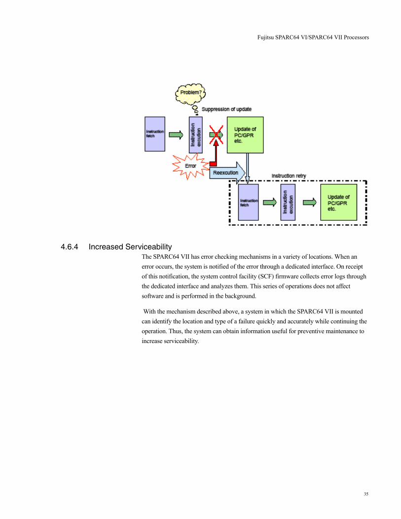
4.6.3 Synchronous Update Method and Instruction RetryAs shown in the explanation of the instruction execution block, the SPARC64 VII uses the synchronous update method. When an error is detected, all the instructions being executed at this time is canceled. Intermediate results before commitment can be discarded, and only results updated by instructions that have been completed without encountering any errors remain in programmable resources. Therefore, not only can the destruction of programmable resources due to errors be prevented, hardware can also perform an instruction retry after error detection. Even in case of a hang-up, because stalled instructions can be discarded once and then retried from the beginning, there is a possibility of recovery.
Instruction retry is triggered by an error and is automatically started. A retry is performed instruction by instruction to increase the chance of normal execution. When the execution is completed normally, the state automatically returns to the normal execution state. During this period, no software intervention is required, and if the instruction retry succeeds, the error does not affect software. An instruction retry is repeated until the number of retry times reaches the threshold, and when the threshold is exceeded, the occurrence of the error is reported to software by an interrupt.
Type Error detection method Protection method
Register Integer register SECDED ECC
Floating-point register Parity
PC, PSTATE, etc. Parity
Computation input-output register Parity
Execution unitAddition and subtraction, division, shift, and graphic operation
Parity prediction
Multiplication Parity prediction + residue check
34
Fujitsu SPARC64 VI/SPARC64 VII Processors
4.6.4 Increased ServiceabilityThe SPARC64 VII has error checking mechanisms in a variety of locations. When an error occurs, the system is notified of the error through a dedicated interface. On receipt of this notification, the system control facility (SCF) firmware collects error logs through the dedicated interface and analyzes them. This series of operations does not affect software and is performed in the background.
With the mechanism described above, a system in which the SPARC64 VII is mounted can identify the location and type of a failure quickly and accurately while continuing the operation. Thus, the system can obtain information useful for preventive maintenance to increase serviceability.
35
I/O Subsystem
5. I/O Subsystem
A growing reliance on compute systems for every aspect of business operations brings along the need to store and process ever-increasing amounts of information. Powerful I/O subsystems are crucial to effectively moving and manipulating these large data sets. Fujitsu SPARC Enterprise servers deliver exceptional I/O expansion and performance, enabling organizations to scale systems and accommodate evolving data storage needs.
5.1 I/O Subsystem ArchitectureThe use of PCI technology is key to the performance of the I/O subsystem within Fujitsu SPARC Enterprise servers. A PCIe bridge supplies the connection between the main system and all components of the I/O unit, such as PCI-X slots, PCIe slots, and internal drives. The PCI Express bus also enables the connection of external I/O devices by using internal PCI slots or connecting an External I/O Expansion Unit.
In order to facilitate hot-plug of PCIe and PCI-X adapter cards, Fujitsu SPARC Enterprise servers utilize PCI cassettes. PCI cards which support PCI Hot Plug can be mounted by administrators into a PCI cassette and inserted into an internal PCI slot or External I/O Expansion Unit of a running Fujitsu SPARC Enterprise server.
5.1.1 Fujitsu SPARC Enterprise Midrange Server I/O SubsystemThe Fujitsu SPARC Enterprise M4000 supports one IOU, while the Fujitsu SPARC Enterprise M5000 supports two IOUs. A single PCIe bridge connects each IOU to the system controllers and a PCIe to PCI-X bridge enables Fujitsu SPARC Enterprise midrange servers to include on-board PCI-X slots. The single IOU on the Fujitsu SPARC Enterprise M4000 contains four PCIe slots and one PCI-X slot. The two IOUs on the Fujitsu SPARC Enterprise M5000 contain a total of eight PCIe slots and two PCI-X slots (Figure 5-1 and Figure 5-2). In addition, an External I/O Expansion Unit increases the number of available PCI slots on midrange Fujitsu SPARC Enterprise servers (Table 5-2).
36

I/O Subsystem
Figure 5-1. Fujitsu SPARC Enterprise M4000 I/O subsystem architecture.
Figure 5-2. Fujitsu SPARC Enterprise M5000 I/O subsystem architecture.
5.1.2 Fujitsu SPARC Enterprise High-end Server I/O subsystemTwo PCIe bridges connect the IOU on each system board to a crossbar switch. Each PCIe bridge also controls communications to four PCIe slots on the system board (Figure 5-3).
Gigabit Ethernet Ports
4
PCIe to PCI-X Bridge
PCI-X Slot
IOU
PCIeBridge
PCIe PHY
PCIe PHY
PCIeSwitch
PCIe Slot
PCIe Slot
PCIe Slot
PCIe Slot
8 Lanes
8 Lanes
8 Lanes
8 Lanes
SATA Ports (4)
Motherboard8 Lanes
Gigabit Ethernet Ports
4
PCIe to PCI-X Bridge
PCI-X Slot
IOU
PCIeBridge
PCIe PHY
PCIe PHY
PCIeSwitch
8 LanesPCIe Slot
PCIe Slot
PCIe Slot
PCIe Slot
8 Lanes
8 Lanes
8 Lanes
8 Lanes
SATA Ports (4)
Gigabit Ethernet Ports
4
PCIe to PCI-X Bridge
PCI-X Slot
IOU
PCIeBridge
PCIe PHY
PCIe PHY
PCIeSwitchPCIe Slot
PCIe Slot
PCIe Slot
PCIes Slot
8 Lanes
8 Lanes
8 Lanes
8 Lanes
SATA Ports (4)
Motherboard
8 Lanes
37

I/O Subsystem
Figure 5-3. Fujitsu SPARC Enterprise M8000 and Fujitsu SPARC Enterprise M9000 I/O subsystem.
A Fujitsu SPARC Enterprise M8000 and Fujitsu SPARC Enterprise M9000 IOU contains eight PCI Express slots with the total number of PCI slots for these servers dependent upon the number of mounted system boards. The maximum number of internal PCIe slots for Fujitsu SPARC Enterprise high-end servers is listed in Table 5-1. In addition, an External I/O Expansion Unit can be added to a Fujitsu SPARC Enterprise server in order to increase the total number of available PCI slots (Table 5-2).
Table 5-1. Fujitsu SPARC Enterprise high-end server internal PCI slot counts.
PCIe Slot
PCIe Slot
PCIe Slot
PCIe Slot
PCIe Slot
PCIe Slot
PCIe Slot
PCIe Slot
PCIe PHY
PCIe PHY
PCIe PHY
PCIe PHY
8 Lanes
8 Lanes
8 Lanes
8 Lanes
8 Lanes
8 Lanes
8 Lanes
8 Lanes
PCIeBridge
(8)
PCIeBridge
(8)
I/O Board
PCIeto PCI-XBridge
Base I/O Board
SAS
Gigabit Ethernet
DVD
DATEXP
EXP
Fujitsu SPARC Enterprise Model Maximum Number of Internal PCIe slots
M8000 32
M9000 (32 CPU configuration) 64
M9000 (64 CPU configuration) 128
38
I/O Subsystem
5.2 Internal PeripheralsWhile disk and tape devices are directly integrated into Fujitsu SPARC Enterprise midrange servers, an add-on base I/O card enables access to internal devices on high-end Fujitsu SPARC Enterprise servers. All Fujitsu SPARC Enterprise servers support one internal DVD drive and an optional DAT tape drive. A Fujitsu SPARC Enterprise M9000 with an expansion cabinet supports two internal DVD drives and the option for two internal DAT tape drives. Fujitsu SPARC Enterprise servers each support multiple internal Serial Attached SCSI (SAS) 2.5-inch hard disk drives.
39
I/O Subsystem
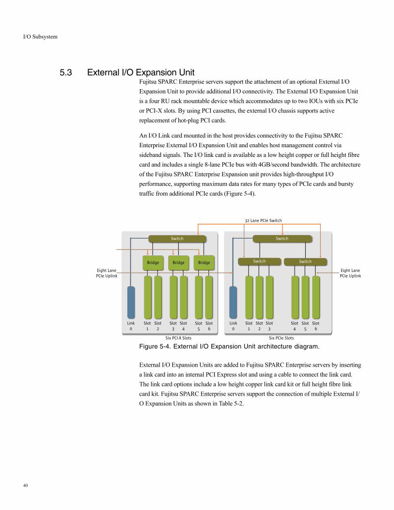
5.3 External I/O Expansion UnitFujitsu SPARC Enterprise servers support the attachment of an optional External I/O Expansion Unit to provide additional I/O connectivity. The External I/O Expansion Unit is a four RU rack mountable device which accommodates up to two IOUs with six PCIe or PCI-X slots. By using PCI cassettes, the external I/O chassis supports active replacement of hot-plug PCI cards.
An I/O Link card mounted in the host provides connectivity to the Fujitsu SPARC Enterprise External I/O Expansion Unit and enables host management control via sideband signals. The I/O link card is available as a low height copper or full height fibre card and includes a single 8-lane PCIe bus with 4GB/second bandwidth. The architecture of the Fujitsu SPARC Enterprise Expansion unit provides high-throughput I/O performance, supporting maximum data rates for many types of PCIe cards and bursty traffic from additional PCIe cards (Figure 5-4).
Figure 5-4. External I/O Expansion Unit architecture diagram.
External I/O Expansion Units are added to Fujitsu SPARC Enterprise servers by inserting a link card into an internal PCI Express slot and using a cable to connect the link card. The link card options include a low height copper link card kit or full height fibre link card kit. Fujitsu SPARC Enterprise servers support the connection of multiple External I/O Expansion Units as shown in Table 5-2.
Switch
BridgeBridge
Switch
Switch SwitchBridge
Link0
Slot1
Slot2
Slot3
Slot4
Slot5
Slot6
Link0
Slot1
Slot2
Slot3
Slot4
Slot5
Slot6
Six PCIe SlotsSix PCI-X Slots
Eight LanePCIe Uplink
Eight LanePCIe Uplink
32 Lane PCIe Switch
40
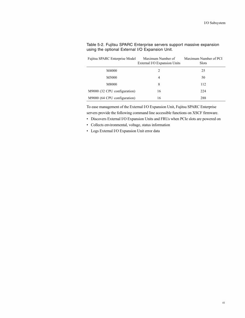
I/O Subsystem
Table 5-2. Fujitsu SPARC Enterprise servers support massive expansion using the optional External I/O Expansion Unit.
To ease management of the External I/O Expansion Unit, Fujitsu SPARC Enterprise servers provide the following command line accessible functions on XSCF firmware.• Discovers External I/O Expansion Units and FRUs when PCIe slots are powered on• Collects environmental, voltage, status information• Logs External I/O Expansion Unit error data
Fujitsu SPARC Enterprise Model Maximum Number of External I/O Expansion Units
Maximum Number of PCI Slots
M4000 2 25
M5000 4 50
M8000 8 112
M9000 (32 CPU configuration) 16 224
M9000 (64 CPU configuration) 16 288
41
Reliability, Availability, and Serviceability
6. Reliability, Availability, and Serviceability
Reducing downtime — both planned and unplanned — is critical for IT services. System designs must include mechanisms that foster fault resilience, quick repair, and even rapid expansion, without impacting the availability of key services. Specifically designed to support complex, network computing solutions and stringent high-availability requirements, the systems in the Fujitsu SPARC Enterprise server family include redundant and hot-swap system components, diagnostic and error recovery features throughout the design, and built-in remote management features. The advanced architecture of these reliable servers enables high levels of application availability and rapid recovery from many types of hardware faults, simplifying system operation and lowering costs for enterprises.
6.1 Redundant and Hot-Swap ComponentsToday’s IT organizations are challenged by the pace of non-stop business operations. In a networked global economy revenue opportunities remain available around the clock, forcing planned downtime windows to shrink and in some cases disappear entirely. To meet these demands, Fujitsu SPARC Enterprise servers employ built-in redundant and hot-swap hardware to help mitigate the disruptions caused by individual component failures or changes to system configurations. In fact, these systems are able to recover from hardware failures — often with no impact to users or system functionality.
Fujitsu SPARC Enterprise servers feature redundant, hot-swap power supply and fan units, as well as the option to configure multiple CPUs, memory DIMMs, and I/O cards. Administrators can create redundant internal storage by combining Fujitsu SPARC Enterprise server hot-swap disk drives with disk mirroring software. High-end servers also include redundant, hot-swap service processors, and Fujitsu SPARC Enterprise M9000 include degradable Crossbar Units and redundant Clock Control Units. If a fault occurs, these duplicated components can enable continued operation. Depending upon the component and type of error, the system may continue to operate in a degraded mode or may reboot — with the failure automatically diagnosed and the relevant component automatically configured out of the system. In addition, hot-swap hardware within the Fujitsu SPARC Enterprise servers speeds service and allows for simplified replacement or addition of components, without a need to stop the system.
42

Reliability, Availability, and Serviceability
6.2 Dynamic DomainsIn order to reduce costs and administrative burden, many enterprises look to server consolidation. However, organizations require tools that increase the security and effectiveness of hosting multiple applications on a single server. Dynamic Domains (= partitioning feature) enable IT organizations to divide a single large system into multiple, fault-isolated servers each running independent instances of the Solaris OS. With proper configuration, hardware or software faults in one domain remain isolated and unable to impact the operation of other domains. Each domain within a single server platform can even run a different version of the Solaris OS, making this technology extremely useful for pre-production testing of new or modified applications. The maximum number of Dynamic Domains by server is itemized in Table 6-1.
Table 6-1. Dynamic Domains limits for Fujitsu SPARC Enterprise servers.
6.2.1 eXtended System BoardDynamic Domains provide a very effective tool for consolidation and enable the ideal separation of resources. It creates the highest level of isolation at systemboard and CPU level to meet the requirements of customers for different partition sizes but with the best possible service availability. Some will require total hardware isolation capability while others slightly less, but still want the ability to create a higher number of domains with computing power that more precisely matches their current workloads. To fully meet both of these needs, the Fujitsu SPARC Enterprise server family provides eXtended System Boards (XSB) as the basis for their partitioning capability. They in fact supports the same levels of flexibility and reliability as the previous generations of Fujitsu SPARC/Solaris server PRIMEPOWER.
To use a physical system board, the hardware resources on the board are divided, reconfigured as eXtended System Boards, and assigned to a Dynamic Domains. There are two types of eXtended System Boards. An XSB that consists of an entire system board is called a Uni-XSB. Alternatively, a system board or motherboard that is logically divided into four parts is called a Quad-XSB. The following diagrams depict the logical division lines within each type of Fujitsu SPARC Enterprise server (Figure 6-1, Figure 6-2, and Figure 6-3).
Using eXtended system boards enables granular, sub-system board assignment of compute resources to Dynamic Domains. A Dynamic Domains can consist of any combination of Uni-XSBs and Quad-XSBs, providing enterprises the ability to perform
Fujitsu SPARC Enterprise Model Maximum Number of Domains
M4000 2
M5000 4
M8000 16
M9000 24
43
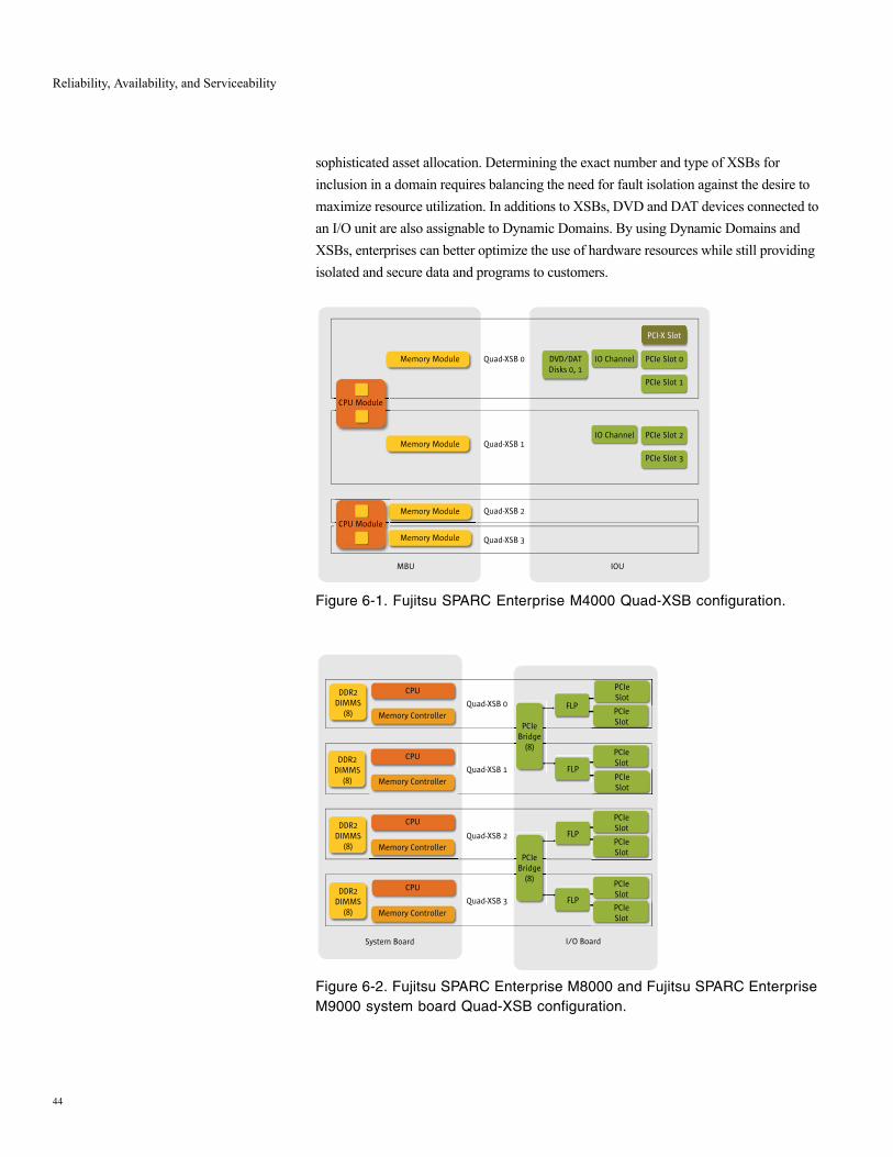
Reliability, Availability, and Serviceability
sophisticated asset allocation. Determining the exact number and type of XSBs for inclusion in a domain requires balancing the need for fault isolation against the desire to maximize resource utilization. In additions to XSBs, DVD and DAT devices connected to an I/O unit are also assignable to Dynamic Domains. By using Dynamic Domains and XSBs, enterprises can better optimize the use of hardware resources while still providing isolated and secure data and programs to customers.
Figure 6-1. Fujitsu SPARC Enterprise M4000 Quad-XSB configuration.
Figure 6-2. Fujitsu SPARC Enterprise M8000 and Fujitsu SPARC Enterprise M9000 system board Quad-XSB configuration.
Memory Module
Memory Module
Memory Module
Memory Module
Quad-XSB 0
Quad-XSB 1
Quad-XSB 2
Quad-XSB 3
MBU IOU
IO ChannelDVD/DATDisks 0, 1
CPU Module
PCI-X Slot
PCIe Slot 0
PCIe Slot 1
IO Channel PCIe Slot 2
PCIe Slot 3
CPU Module
DDR2DIMMS
(8)
DDR2DIMMS
(8)
DDR2DIMMS
(8)
DDR2DIMMS
(8)
CPU
Memory Controller
CPU
Memory Controller
CPU
Memory Controller
CPU
Memory Controller
Quad-XSB 0
Quad-XSB 1
Quad-XSB 2
Quad-XSB 3
System Board I/O Board
PCIeSlot
FLP
PCIeSlot
PCIeSlot
PCIeSlot
PCIeSlot
PCIeSlot
PCIeSlot
PCIeSlot
FLP
FLP
FLP
PCIeBridge
(8)
PCIeBridge
(8)
44
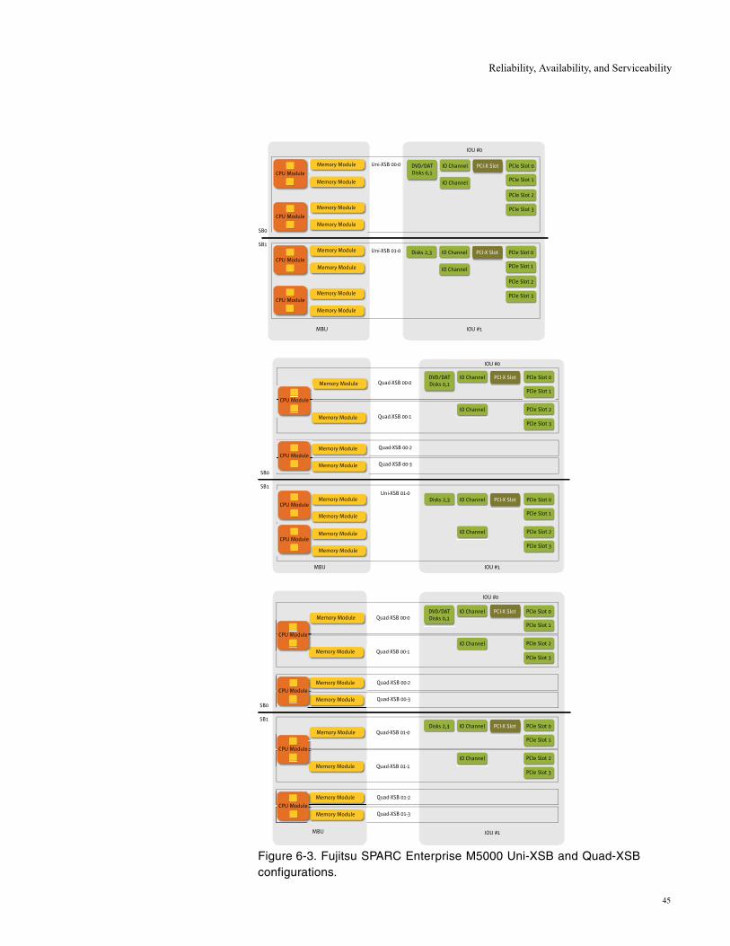
Reliability, Availability, and Serviceability
Figure 6-3. Fujitsu SPARC Enterprise M5000 Uni-XSB and Quad-XSB configurations.
Memory Module
Memory Module
Memory Module
Memory Module
Memory Module
Memory Module
Memory Module
Memory Module
Uni-XSB 00-0
Uni-XSB 01-0
MBU IOU #1
SB0
SB1
IO ChannelDVD/DATDisks 0,1
PCI-X Slot
IO Channel
PCIe Slot 0
PCIe Slot 1
PCIe Slot 2
PCIe Slot 3
IO ChannelDisks 2,3 PCI-X Slot
IO Channel
PCIe Slot 0
PCIe Slot 1
PCIe Slot 2
PCIe Slot 3
CPU Module
CPU Module
CPU Module
CPU Module
IOU #0
Quad-XSB 01-0
Quad-XSB 01-1
Quad-XSB 01-2
Quad-XSB 01-3
Memory Module
Memory Module
Memory Module
Memory Module
IO ChannelDisks 2,3 PCI-X Slot
IO Channel
PCIe Slot 0
PCIe Slot 1
PCIe Slot 2
PCIe Slot 3
MBU IOU #1
SB0
SB1
Quad-XSB 00-0
Quad-XSB 00-1
Quad-XSB 00-2
Quad-XSB 00-3
Memory Module
Memory Module
Memory Module
Memory Module
IO ChannelDVD/DATDisks 0,1
PCI-X Slot
IO Channel
PCIe Slot 0
PCIe Slot 1
PCIe Slot 2
PCIe Slot 3
CPU Module
CPU Module
CPU Module
CPU Module
IOU #0
Uni-XSB 01-0
MBU IOU #1
SB0
SB1
Quad-XSB 00-0
Quad-XSB 00-1
Quad-XSB 00-2
Quad-XSB 00-3
Memory Module
Memory Module
Memory Module
Memory Module
IO ChannelDVD/DATDisks 0,1
PCI-X Slot
IO Channel
PCIe Slot 0
PCIe Slot 1
PCIe Slot 2
PCIe Slot 3
IO ChannelDisks 2,3 PCI-X Slot
IO Channel
PCIe Slot 0
PCIe Slot 1
PCIe Slot 2
PCIe Slot 3
Memory Module
Memory Module
Memory Module
Memory Module
CPU Module
CPU Module
CPU Module
CPU Module
IOU #0
45

Reliability, Availability, and Serviceability
6.3 Dynamic ReconfigurationDynamic Reconfiguration technology provides added value to Dynamic Domains by providing administrators with the ability to shift resources without taking the system offline. This technology enables enterprises to perform maintenance, live upgrades, and physical changes to system hardware resources, while the server continues to execute applications. Dynamic Reconfiguration even enables multiple simultaneous changes to hardware configurations without interrupting critical systems.
The ability to remove and add components such as CPUs, memory, and I/O subsystems from a running system helps reduce system downtime. Using Dynamic Reconfiguration simplifies maintenance and upgrades by eliminating the need for system reboots after hardware configuration changes.
Note – The supported firmware and OS conditions are different depending on the installed components. The system reboot is required to update the firmware/OS when the installed version doesn't meet the condition.
46

Reliability, Availability, and Serviceability
6.4 Advanced Reliability FeaturesAdvanced reliability features included within the components of Fujitsu SPARC Enterprise servers increase the overall stability of these platforms. For example, Fujitsu SPARC Enterprise M4000/M5000/M8000/M9000 include multiple system controllers, and high-end servers include degradable crossbar switches to provide redundancy within the system bus. Reduced component count and complexity within the server architecture contributes to reliability. In addition, advanced CPU integration and guaranteed data path integrity provide for autonomous error recovery by the SPARC64 VI processor or SPARC 64 VI/SPARC 64 VII processors, reducing the time to initiate corrective action and subsequently increasing uptime.
Solaris Predictive Self Healing software further enhances the reliability of Fujitsu SPARC Enterprise servers. The implementation of Solaris Predictive Self Healing software for Fujitsu SPARC Enterprise servers enables constant monitoring of all CPUs and memory. Depending upon the nature of the error, persistent CPU soft errors can be resolved by automatically offlining either a thread, core, or entire CPU. In addition, the memory page retirement capability enables memory pages to be taken offline proactively in response to multiple corrections to data access for a specific memory DIMM.
47

Reliability, Availability, and Serviceability
6.5 Error Detection, Diagnosis, and RecoveryFujitsu SPARC Enterprise servers feature important technologies that correct failures early and keep marginal components from causing repeated downtime. Architectural advances which inherently increase reliability are augmented by error detection and recovery capabilities within the server hardware subsystems. Ultimately, the following features work together to raise application availability.
• End-to-end data protection detects and corrects errors throughout the system, ensuring complete data integrity.
• State-of-the-art fault isolation enables the Fujitsu SPARC Enterprise servers to isolate errors within component boundaries and offline only the relevant chips instead of the entire component. Isolating errors down to the chip improves stability and provides continued availability of maximum compute power. This feature applies to CPUs, memory access controllers, crossbar ASICs, system controllers, and I/O ASICs.
• Constant environmental monitoring provides a historical log of all pertinent environmental and error conditions.
• The host watchdog feature of Fujitsu SPARC Enterprise server family periodically checks for operation of software, including the domain operating system. This feature also uses the XSCF firmware to trigger error notification and recovery functions.
• Fujitsu SPARC Enterprise servers support dynamic CPU resource deallocation which includes processor fault detection, isolation, and recovery. This feature dynamically reallocates CPU resources into an operational system using Dynamic Reconfiguration without interrupting the applications that are running.
• Periodic component status checks are performed to determine the status of many system devices to detect signs of an impending fault. Recovery mechanisms are triggered to prevent system and application failure.
• Error logging, multistage alerts, electronic FRU identification information, and system fault LED indicators all contribute to rapid problem resolution.
48

System Management
7. System Management
Providing hands-on, local system administration for server systems is no longer realistic for most organizations. Around the clock system operation, disaster recovery hot sites, and geographically dispersed organizations lead to requirements for remote management of systems. One of the many benefits of Fujitsu servers is the support for lights-out datacenters, enabling expensive support staff to work in any location with network access. The Fujitsu SPARC Enterprise system design, combined with a powerful eXtended System Control Facility (XSCF), XSCF Control Package, and Fujitsu’s system management software enables administrators to remotely execute and control nearly any task that does not involve physical access to hardware.These management tools and remote functions lower administrative burden, saving organizations time and reducing operational expenses.
7.1 Extended System Control FacilityThe eXtended System Control Facility provides the heart of remote monitoring and management capabilities in midrange and high-end Fujitsu SPARC Enterprise servers. The XSCF consists of a dedicated processor that is independent of the server system and runs the XSCF Control Package. The Domain to Service Processor Communication Protocol (DSCP) is used for communication between the XSCF and the server. The DSCP protocol runs on a private TCP/IP-based or PPP-based communication link between the service processor and each domain. While input power is supplied to the server, the XSCF constantly monitors the system even if all domains are inactive.
The XSCF regularly monitors the environmental sensors, provides advance warning of potential error conditions, and executes proactive system maintenance procedures as necessary. For example, the XSCF can initiate a server shutdown in response to temperature conditions which might induce physical system damage. The XSCF Control Package running on the service processor enables administrators to remotely control and monitor domains, as well as the platform itself.
Using a network or serial connection to the XSCF, operators can effectively administer the server from anywhere on the network. Remote connections to the service processor run separately from the operating system and provide the full control and authority of a system console.
49
System Management
7.1.1 Redundant XSCFOn Fujitsu SPARC Enterprise M8000 and M9000, one XSCF is configured as active and the other is configured as a standby. The XSCF network between the two service processors enables the exchange of system management information. In case of failover, the service processors are already synchronized and ready to change roles.
7.1.2 DSCP Network The Domain to Service Processor Communication Protocol service provides a secure TCP/IP and PPP-based communications link between the service processor and each domain. Without this link, the XSCF cannot communicate with the domains. The service processor requires one IP address dedicated to the DSCP service on its side of the link, and one IP address on each domain’s side of the link. In a system with more than one XSCF, the standby XSCF does not communicate with the domains. In the event of a failover of the XSCF, the newly active XSCF assumes the IP address of the failed-over service processor.
7.1.3 XSCF Control PackageThe XSCF Control Package enables users to control and monitor Fujitsu SPARC Enterprise server platforms and individual Dynamic Domains (= partitioning feature) quickly and effectively. The XSCF Control Package provides a command line interface (CLI) and Web browser user interface that gives administrators and operators access to all system controller functionality. Password-protected accounts with specific administration capabilities also provide system security for domain consoles. Communication between the XSCF and individual domains uses an encrypted connection based on Secure Shell (SSH) and Secure Socket Layer (SSL), enabling secure, remote execution of commands provided with the XSCF Control Package.
The XSCF Control Package provides the interface for the following key server functions.
• Execution of Dynamic Reconfiguration tasks to logically attach or detach installed system boards from the operating system while the domain continues to run applications without interruption.
• Domain administration which consist of creating logical system boards comprised of Uni-XSB and Quad-XSB units.
• Audit administration includes the logging of interactions between the XSCF and the domains.
• Monitor and control of power to the components in all Fujitsu SPARC Enterprise servers.
• Interpretation of hardware information presented, and notification of impending problems such as high temperatures or power supply problems, as well as access to the system administration interface.
50

System Management
• Integration with the Fault Management Architecture of the Solaris OS to improve availability through accurate fault diagnosis and predictive fault analysis.
• Execution and monitoring of diagnostic programs, such as the Open Boot Prom (OBP) and power-on self-test (POST).
• Execution of Fujitsu Capacity On Demand operations which provide the ability to stage and then later activate additional processing resources.
• Monitoring of the dual XSCF configuration on Fujitsu SPARC Enterprise M8000 and Fujitsu SPARC Enterprise M9000 for failure and performing an automatic failover if needed.
7.1.4 Role Based System ManagementThe XSCF Control Package enables the independent administration of several autonomous domains by different system administrators and operators — all cooperating within a single Fujitsu SPARC Enterprise platform. This management software supports multiple user accounts which are organized into groups. Different privileges are assigned to each group. Privileges allow a user to perform a specific set of actions on a specific set of hardware, including physical components, domains, or physical components within a domain. In addition, a user can possess multiple, different privileges on any number of domains.
7.1.5 Server Management SoftwareMonitoring and control software is essential in managing today's server infrastructure and the complications of IT device distribution. Fujitsu's Server System Manager (SSM) enables management of all Solaris, Linux, and Windows servers. Plus, in combination with Systemwalker Fujitsu's integrated systems management software, SSM provides autonomic operation and ensures you maintain business continuity as your IT environment changes to match your business.
7.1.6 Server System Manager (SSM)SMM software provides a common server management environment for PRIMEQUEST mission-critical open servers, industry standard PRIMERGY servers, and SPARC Enterprise UNIX servers. Graphical server management views and functions for hardware configuration and hardware monitoring make SSM the easy option in a heterogeneous server environment.
Not only are you able to monitor the status of multiple servers you can also control server power from the same single consistent display. Ease of use continues as all server configurations are viewed using a single tree structure and common formats. This lets you check server component status a glance. Racked servers and related items are shown relative to their rack positions using life-like server images. This further simplifies status monitoring of server resources such as CPU and memory. Importantly, the networked
51

System Management
nature of SSM means you can perform power on/off and other operations from any location with a management display.
SSM is also intimately related to the eXtended Server Control Facility (XSCF), a unique management processor built into Fujitsu servers. That is why you can easily identify failed components on the SSM display. Also, as XSCF detects failures, it pushes that information to SSM while notifying you directly by mail, or via SNMP trap to Systemwalker. You are able to set thresholds for such notification ensuring only important events are escalated directly to you. All failures are notified to the monitoring screen and can be on-sent to alternative destinations via e-mail.
With systems running partitions, such as SPARC Enterprise, partition operation management is also supported letting you monitor resources and reconfigure partitions using the resource Dynamic Reconfiguration (DR) function. In a similar way Solaris containers can also be managed via special clients. An interactive GUI wizard lets you construct virtual Solaris zones, change settings, and delete, boot, and shut down containers and zones.
With SSM server operation management is greatly simplified, letting you concentrate on hardware problem resolution and other critical work. As a result your work and the work of other administrators will be both reduced and more productive.
7.1.7 Enhanced Support FacilityEnhanced Support Facility is specific software that improves the operation management and the maintainability of SPARC Enterprise servers. Working in combination with XSCF, server configuration, status and error messages can all be displayed. If a problem occurs, the information reported to XSCF ensures the status, of disks, power, PCI cards and OS, is always monitored. It also enables you to display other system information including batch collections, /etc/system file settings, server power on/off scheduling and disk hot swap procedures.
7.1.8 Systemwalker Centric ManagerCentric Manager lets you follow the system operation lifecycle (installation/setup, monitoring, fault recovery, assessment), making it possible for you to create highly-reliable systems. It reduces the workload required for operations management and provides high-value functions for life-cycle tasks. These include the remote distribution of software resources, central monitoring of systems and networks, and prompt resolution of problems from any location. It performs integrated management, operational process standardization (ITIL), while enabling security control of the latest business IT technology such as multi-platform and intranet/Internet environments.
52
The Solaris 10 Operating System
8. The Solaris 10 Operating System
With mission-critical business objectives on the line, enterprises need a robust operating environment with the ability to optimize the performance, availability, security, and utilization of hardware assets. In a class by itself, the Solaris™ 10 OS offers many innovative technologies to help IT organizations improve operations and realize the full potential of Fujitsu SPARC Enterprise servers.
8.1 Observability and PerformanceOrganizations need to make effective use of the power of hardware platforms. The Solaris OS supports near linear scalability from 1 to 72 CPUs (144 cores) and memory addressability that reaches well beyond the physical memory limits of even Fujitsu’s largest server. The following advanced features of the Solaris 10 OS provide IT organizations with the ability to identify potential software tuning opportunities and maximize raw system throughput.
• Solaris Dynamic Tracing framework (DTrace) is a powerful tool that provides a true, system-level view of application and kernel activities, even those running in a Java Virtual Machine. DTrace software safely instruments the running operating system kernel and active applications without rebooting the kernel or recompiling — or even restarting — software. By using this feature, administrators can view accurate and concise information in real time and highlight patterns and trends in application execution. The dynamic instrumentation provided by DTrace enables organizations to reduce the time to diagnose problems from days and weeks to minutes and hours, resulting in faster data-driven fixes.
• The highly scalable, optimized TCP/IP stack in the Solaris 10 OS lowers overhead by reducing the number of instructions required to process packets. This technology also provides support for large numbers of connections and enables server network throughput to grow linearly with the number of CPUs and network interface cards (NICs). By taking advantage of the Solaris 10 OS network stack, organizations can significantly improve application efficiency and performance.
• The memory handling system of the Solaris 10 OS provides multiple page size support in order to enable applications to access virtual memory more efficiently, improving performance for applications that use large memory intensively. In addition, Solaris 10 OS Memory Placement Optimization (MPO) works to ensure that data is stored in memory as close as possible to the processors that accesses it while still maintaining
53
The Solaris 10 Operating System
enough balance within the system. MPO can boost performance in business workloads by as much as 20 percent and as much as 50 percent in some High Performance Computing workloads.
• The Solaris OS multithreaded execution model plays an important role in enabling Fujitsu servers to deliver scalable performance. Improvements to the threading capabilities in the Solaris OS occur with every release, resulting in performance and stability improvements for existing applications without recompiliation.
54
The Solaris 10 Operating System
8.2 AvailabilityThe ability to rapidly diagnose, isolate, and recover from hardware and application faults is paramount for meeting the needs of non-stop business operations. Long standing features of the Solaris OS provide for system self-healing. For example, the kernel memory scrubber constantly scans physical memory, correcting any single-bit errors in order to reduce the likelihood of those problems turning into un-correctable double-bit errors. The Solaris 10 OS takes a big leap forward in self-healing with the introduction of Solaris Fault Manager and Solaris Service Manager technology. With this software, business-critical applications and essential system services can continue uninterrupted in the event of software failures, major hardware component breakdowns, and software misconfiguration problems.
• Solaris Fault Manager software reduces complexity by automatically diagnosing faults in the system and initiating self-healing actions to help prevent service interruptions. The Solaris Fault Manager diagnosis engine produces a fault diagnosis once discernible patterns are observed from a stream of incoming errors. Following error identification, the Solaris Fault Manager provides information to agents that know how to respond to specific faults. Problem components can be configured out of a system before a failure occurs — and in the event of a failure, this feature initiates automatic recovery and application re-start. For example, an agent designed to respond to a memory error might determine the memory addresses affected by a specific chip failure and remove the affected locations from the available memory pool.
• Solaris Service Manager software converts the core set of services packaged with the operating system into first-class objects that administrators can manipulate with a consistent set of administration commands. Using Solaris Service Manager, administrators can take actions on services including start, stop, restart, enable, disable, view status, and snapshot. Service snapshots save a service’s complete configuration, giving administrators a way to roll back any erroneous changes. Snapshots are taken automatically whenever a service starts to help reduce risk by guarding against erroneous errors. The Solaris Service Manager is integrated with Solaris Fault Manager. When a low-level fault is found to impact a higher-level component of a running service, Solaris Fault Manager can direct Solaris Service Manager to take appropriate action.
In addition to handling error conditions, efficiently managing planned downtime greatly enhances availability levels. Tools included with the Solaris OS, such as Solaris Flash and Solaris Live Upgrade software, can help enterprises achieve more rapid and consistent installation of software, upgrades, and patches, leading to improved uptime.
• The Solaris Flash facility enables IT organizations to quickly install and update systems with an OS configuration tailored to enterprise needs. This technology provides tools to system administrators for building custom rapid-install images—including
55

The Solaris 10 Operating System
applications, patches, and parameters—that can be installed at a data rate close to the full speed of the hardware.
• The Solaris Live Upgrade facility provides mechanisms to upgrade and manage multiple on-disk instances of the Solaris OS. This technology enables system administrators to install a new operating system on a running production system without taking it offline, with the only downtime for the application being the time necessary to reboot the new configuration.
56

The Solaris 10 Operating System
8.3 SecurityToday’s increasingly connected systems create benefits and challenges. While the global network offers greater revenue opportunities, enterprises must pay close attention to security concerns. The most secure OS on the planet, the Solaris 10 OS provides features previously only found in military-grade Trusted Solaris OS. These capabilities enable the strong controls required by governments and financial institutions but also benefit all enterprises focused on security concerns and requirements for auditing capabilities.
• User Rights Management and Process Rights Management work in conjunction with Solaris Container virtualization technology to enable multiple applications to securely share the same domain. Security risks are reduced by granting users and applications only the minimum capabilities needed to perform assigned duties. Best yet, unlike other solutions on the market, no application changes are required to take advantage of these security enhancements.
• Solaris Trusted Extensions extend the existing Solaris 10 OS security policy with labeling features previously only available in highly specialized operating systems or appliances. These extensions deliver true multilevel security within a commercial-grade operating system, beneficial to civilian organizations with specific regulatory or information protection requirements.
• Core to the Solaris 10 OS are features which fortify platforms against compromise. Firewall protection technology included within the Solaris 10 OS distribution protects individual systems against attack. In addition, file integrity checking and digitally signed binaries within the Solaris 10 OS enable administrators to verify platforms remain untouched by hackers. Secure remote access capabilities also increase security by centralizing the administration of system access across multiple operating systems.
57
The Solaris 10 Operating System
8.4 Virtualization and Resource ManagementThe economic need to maximize the use of every IT asset often necessitates consolidating multiple applications onto single server platforms. Virtualization techniques enhance consolidation strategies one step further by enabling organizations to create administrative and resource boundaries between applications within each domain on a server. Solaris Containers technology provides a breakthrough approach to virtualization and software partitioning, enabling the creation of many private execution environments within a single instance of the Solaris OS. Using this technology, IT organizations can quickly harness and provision idle compute power into a secure, isolated runtime environment for a new deployments without increasing the number of operating system instances to manage. In addition, hosting applications within individual Solaris Containers provides administrators the ability to exert fine-grained control over rights and resources within a consolidated server.
In addition, Solaris Resource Manager software enables the allocation of computing resources within Solaris Containers and among individual tasks and users in a structured, policy-driven fashion. Using the Solaris OS resource management facilities to proactively allocate, control, and monitor system resources —such as CPU time, processes, virtual memory, connect time, and logins— on a fine-grained basis helps organizations obtain more predictable service levels. As business needs change, Solaris Resource Manager software helps enterprises to regularly set new priorities for the use of compute resources. By taking advantage of Solaris Containers and Solaris Resource Manager software, organizations can improve resource utilization, reduce downtime, and lower solution costs.
58
Summary
9. Summary
To support the endless demand for scalability, reliability, and manageability in the datacenter, infrastructures need to provide ever-increasing performance and capacity while becoming simpler to deploy, adjust, and manage. Fujitsu SPARC Enterprise servers outfitted with SPARC64 VI processors or SPARC 64 VI/SPARC 64 VII processors, large memory capacity, an inherently reliable architecture, and an eXtended system control facility deliver new levels of power, availability, and ease-of-use to enterprises. The sophisticated resource control enabled by Dynamic Domains, eXtended System Boards, and Dynamic Reconfiguration further increase the value of these servers by enabling enterprises to optimize the use of these hardware assets. By taking advantage of fast, scalable Fujitsu SPARC Enterprise servers, organizations gain extraordinary power and flexibility — a strategic asset in the quest to get ahead and stay ahead of the competition.
For More InformationTo learn more about innovative Fujitsu products and the benefits of Fujitsu SPARC Enterprise servers and the Solaris OS, contact a Fujitsu sales representative or consult the Fujitsu Web site listed in the Table below.
Related Web sites
(Reference material)
Processor for a UNIX Server "SPARC64 V", Aug 2004, Fujitsu Limited
Web Site URL Description
http://www.fujitsu.com/sparcenterprise/ Fujitsu SPARC Enterprise servers
http://www.fujitsu.com/global/services/computing/ Fujitsu Computing products
http://www.fujitsu.com/global/ Fujitsu Global portal
59

Summary
60
