cool zone series electric fryers - static-pt.com
TRANSCRIPT

Dean, a member of the Commercial Food Equipment Service Association, recommends usingCFESA Certified Technicians.
Price: $6.0024-Hour Service Hotline 1-800-551-8633
819-5867
Cool Zone Series Electric Fryers
Installation & O
peration Manual
Models 714E, 1414E, 1818E & 2020E

PLEASE READ ALL SECTIONS OF THIS MANUAL AND RETAIN FOR FUTUREREFERENCE.
This product has been certified as commercial cooking equipment and must beinstalled by professional personnel as specified.
We suggest installation, maintenance and repairs should be performed by your local Factory Authorized Service Center.
INSTRUCTIONS TO BE FOLLOWED IN CASE THE USER SMELLS GAS ARE TO BE POSTEDIN A PROMINENT LOCATION. THIS INFORMATION SHALL BE OBTAINED BY CONTACTING
THE LOCAL GAS COMPANY OR GAS SUPPLIER.
FOR YOUR SAFETY, DO NOT STORE OR USE GASOLINE OR OTHER FLAMMABLE VAPORS AND LIQUIDS IN THE VICINITY
OF THIS OR ANY OTHER GAS APPLIANCE.
IMPORTANTSAFE AND SATISFACTORY OPERATION OF YOUR EQUIPMENT DEPENDS
ON IT’S PROPER INSTALLATION. INSTALLATION MUST BEPLANNED IN ACCORDANCE WITH ALL APPLICABLE STATE
AND LOCAL CODES.
WARNINGSafety labels are a required component of this unit. If missing, or not legible, they must bereplaced. Inspect periodically and replace if necessary. Replacement labels are available
free of charge from the factory.

TABLE OF CONTENTS
1. DESCRIPTION AND SPECIFICATIONS.....................................................12. PRE-INSTALLATION ......................................................................................23. RECEIVING AND INSTALLING THE FRYER ............................................24. INITIAL START-UP .........................................................................................35. DAILY OPERATION ........................................................................................46. CLEANING & MAINTENANCE.....................................................................57. TROUBLESHOOTING.....................................................................................68. RECOMMENDED SPARE PARTS/PARTS LIST .........................................79. FACTORY SERVICE & PARTS ORDERING..............................................1110. SPECIFICATIONS ......................................................................................1211. WIRING DIAGRAMS..................................................................................13LIMITED WARRANTY .......................................................................................17

1
1. DESCRIPTION ANDSPECIFICATIONS
The Dean Industries Electric Deep Fat Fryersare energy-efficient, electrically heated units,listed by the Underwriter's Laboratory, andmanufactured to the following basicperformance and application specifications. Allunits are shipped complete assembled, with anyaccessories packed inside the fryer tank. Allunits are adjusted, tested and inspected at thefactory prior to crating for shipment.
MODEL 714E 1414E 1818E 2020EFRYING VESSEL Frying Area: Oil Capacity
6-3/4x1425#
14x 14"40#
18x18"70#
20x2080#
ELECTRICALREQUIREMENTS: Wattage: Amperage:
18KW208V, 3hp, 49.9 ALLMODELS208V, 1hp, 86.5240V, 3hp, 45.7240V, 1hp, 75.0
APPROX. SHIPPING 115# 153# 190# 200#Note: 1818E and 2020E are also available in 13.5 KWmodels.
VESSEL CONSTRUCTION:
Welded, heavy gauge stainless steel; threeheater elements fixed inside the vessel with aninner chromed wire mesh protective crumbscreen over the elements. Drain tapped intocenter of vessel with front-controlled manualball valve.
BODY CONSTRUCTION:
Welded steel base, with visible surfaces ofbrushed Series 300 stainless steel or paintedsteel. Frame supported by 6" adjustable legs or5" casters on line-ups of multiple units.
OPERATING CONTROLS:
Unit is shipped standard with a liquid bulb filledthermostat or an optional solid statetemperature controller. Either temperaturecontrol is mounted in the cabinet behind the
front door on or near the cabinet floor. Optionalpanel-mounted main power switch, rocker-typereset switch, melt cycle switch, and instantpower switch are mounted on control panel.
Melt Cycle:This feature pulses the heating elements on andoff at a controlled rate. This should be usedwhen the fryer is being used with solidshortening.
Instant power:Except on bulb and capillary type thermostats,this feature by-passes the temperaturecontroller for a pre-set period of time to providemaximum heating power into frying compoundand to allow the operator to anticipate heavyuse.
AUTOMATIC SAFETY FEATURES:
a) High temperature detection to shut offpower to the heating elements should thecontrolling thermostat fail.
b) Optional safety switch built into the drainvalve prohibits element operation with thedrain valve even partially open.
RATING PLATE:
This is riveted to the inside right-hand corner ofthe fryer door.
Information on this plate includes the model andserial numbers; when communicating with thefactory about a unit or requesting special partsor information, this data is essential for properidentification. Other information on this plate isthe kW output of the heaters and electricalrequirements.
ALL DEAN INDUSTRIES DEEP FATFRYERS MUST BE CONNECTED ONLY TOTHE TYPE OF ELECTRICAL SERVICEIDENTIFIED ON THIS RATING PLATE!

2
2. PRE-INSTALLATION
GENERAL:
Installation of any heavy-duty electricalappliance should be made by a licensedelectrician.
STANDARDS:
Installation must be planned in accordance withall applicable state and local codes, taking intoaccount the following standards:
a) Nat'l Electrical Code ANSI/NFPA#70-1984:American National Standards Institute1430 BroadwayNew York, NY 10018
b) NFPA Standards #96 and #211:National Fire Protection Association470 Atlantic AvenueBoston, MA 02110
CAUTION
Local building codes will usually not permit adeep fat fryer with its open tank of hot oil to beinstalled beside an open flame of any type,whether a broiler or the open burner of a range.Check local codes before beginning installation.
AIR SUPPLY & VENTILATION:
The area around the appliance must be keptclear to avoid obstruction to the flow ofventilation air as well as for ease ofmaintenance and service. Under no conditionsis the interior of the fryer's cabinet to be usedfor storage.
a) Means must be provided for anycommercial heavy-duty cookingappliance to exhaust cooking vapors tothe outside of the building.
b) Filters and drip-throughs should be partof any industrial hood, but consult localcodes before constructing and installingany hood.
3. RECEIVING &INSTALLING THE FRYER
UNPACKING:
Check that the container is upright. Useoutward prying - no hammering - to remove thecarton. Check the fryer(s) for visible damage; ifsuch damage has occurred, do not refuseshipment, but contact the carrier and file theappropriate freight claims. Do not contact thefactory, as the responsibility for shippingdamage is between the shipper and the dealeror end-user.
Remove, unwrap, wash, and temporarily setaside any accessories shipped in the fryervessel. These may include:
Basket hanger with basketsWire crumb screenGoofer rod (clean-out rod)Drain pipe extensionLifters, scoopsVessel coverTeflon cleaning brushLegs
LEGS:
Legs should be installed near where theappliance is to be used. After unpacking, raisethe unit about a foot to permit the legs to bescrewed into their couplings, and lower it gentlyto keep any undue strain from the legs andinternal mounting hardware. It is stronglyrecommended that a pallet or lift jack be usedrather than tilting.
POSITIONING:
Do not push against any of the edges of the unitin an attempt to adjust its position. Lift it slightlyand place it where it is to be installed. Althoughall metal parts are deburred duringmanufacture, accidents could occur if the fryer(or a line-up) should move suddenly while beingpushed into position by hand. Pushing a unit(rather than using a lift jack) also increases theprobability of bending the leg spindles or theinternal coupling connectors.
3
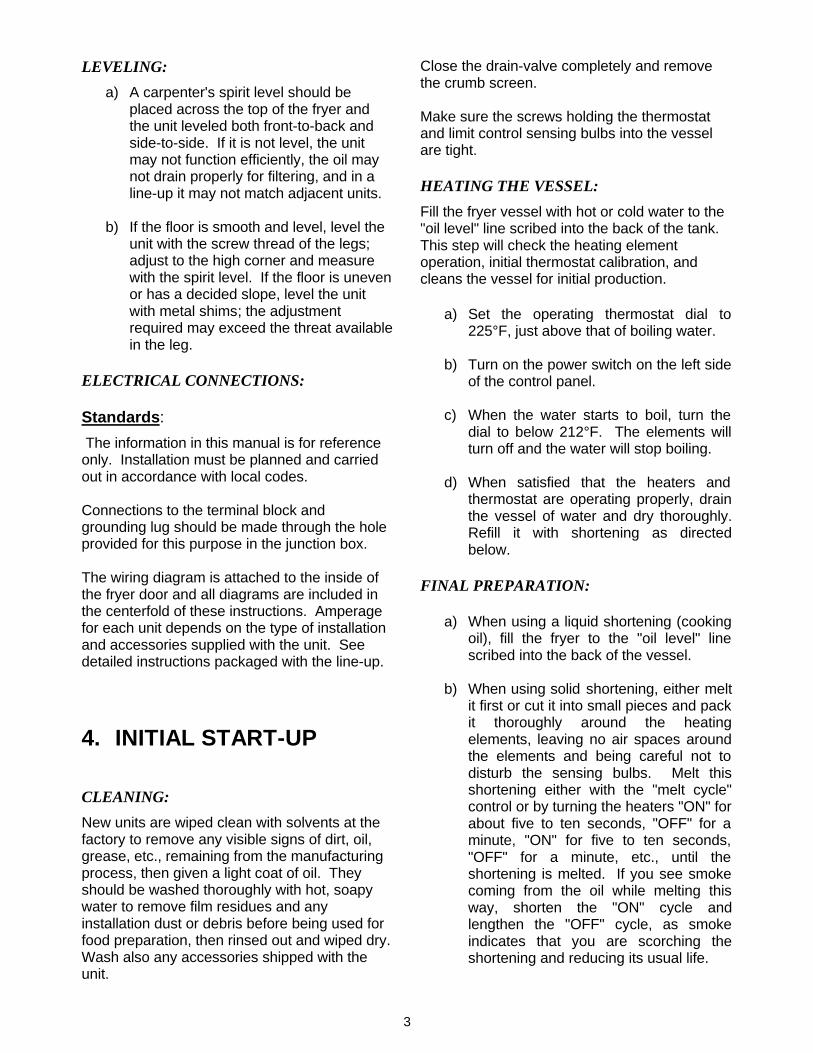
LEVELING:
a) A carpenter's spirit level should beplaced across the top of the fryer andthe unit leveled both front-to-back andside-to-side. If it is not level, the unitmay not function efficiently, the oil maynot drain properly for filtering, and in aline-up it may not match adjacent units.
b) If the floor is smooth and level, level theunit with the screw thread of the legs;adjust to the high corner and measurewith the spirit level. If the floor is unevenor has a decided slope, level the unitwith metal shims; the adjustmentrequired may exceed the threat availablein the leg.
ELECTRICAL CONNECTIONS:
Standards:
The information in this manual is for referenceonly. Installation must be planned and carriedout in accordance with local codes.
Connections to the terminal block andgrounding lug should be made through the holeprovided for this purpose in the junction box.
The wiring diagram is attached to the inside ofthe fryer door and all diagrams are included inthe centerfold of these instructions. Amperagefor each unit depends on the type of installationand accessories supplied with the unit. Seedetailed instructions packaged with the line-up.
4. INITIAL START-UP
CLEANING:
New units are wiped clean with solvents at thefactory to remove any visible signs of dirt, oil,grease, etc., remaining from the manufacturingprocess, then given a light coat of oil. Theyshould be washed thoroughly with hot, soapywater to remove film residues and anyinstallation dust or debris before being used forfood preparation, then rinsed out and wiped dry.Wash also any accessories shipped with theunit.
Close the drain-valve completely and removethe crumb screen.
Make sure the screws holding the thermostatand limit control sensing bulbs into the vesselare tight.
HEATING THE VESSEL:
Fill the fryer vessel with hot or cold water to the"oil level" line scribed into the back of the tank.This step will check the heating elementoperation, initial thermostat calibration, andcleans the vessel for initial production.
a) Set the operating thermostat dial to225°F, just above that of boiling water.
b) Turn on the power switch on the left sideof the control panel.
c) When the water starts to boil, turn thedial to below 212°F. The elements willturn off and the water will stop boiling.
d) When satisfied that the heaters andthermostat are operating properly, drainthe vessel of water and dry thoroughly.Refill it with shortening as directedbelow.
FINAL PREPARATION:
a) When using a liquid shortening (cookingoil), fill the fryer to the "oil level" linescribed into the back of the vessel.
b) When using solid shortening, either meltit first or cut it into small pieces and packit thoroughly around the heatingelements, leaving no air spaces aroundthe elements and being careful not todisturb the sensing bulbs. Melt thisshortening either with the "melt cycle"control or by turning the heaters "ON" forabout five to ten seconds, "OFF" for aminute, "ON" for five to ten seconds,"OFF" for a minute, etc., until theshortening is melted. If you see smokecoming from the oil while melting thisway, shorten the "ON" cycle andlengthen the "OFF" cycle, as smokeindicates that you are scorching theshortening and reducing its usual life.

4
c) When the fryer vessel is filled and theshortening melted, replace the crumbscreen.
d) Before starting operation, turn theoperating thermostat to the probableworking temperature, wait for thetemperature to stabilize, then check witha high-quality immersion thermometer.
5. DAILY OPERATION
OPENING:
At opening time, always visually check the fryerfor:
a) Power switch "off".
b) Temperature controller dial "OFF".
GENERAL TURN-ON PROCEDURE:
a) If the fryer is empty, pour enough fryingcompound into the fryer to at least cover theheating elements, or fill the vessel to the "oillevel" line scribed on the rear wall. If solidshortening is to be used, melt enough in aseparate container to cover the heatingelements in the bottom of the vessel, thenmelt the rest in the vessel by turning thepower switch off and on.
b) Turn the power switch on; turn thetemperature controller to 350°F(recommended). In less than 30 minutes,
the frying compound temperature willstabilize and be ready for production.
USE OF THE FRYER:
For optimum results, the following generalinformation is offered.
a) For consistent product quality,convenience, and long-term savings,use a high-quality liquid fryingcompound.
b) If using solid shortening, never attemptto melt a block of shortening by setting itwhole in the fryer vessel. This isinefficient and dangerous.
c) Temperature of frying compound.Although 350°F is the usual temperaturerecommended for most cookingoperations, frying should be carried outat the lowest temperature which willproduce a high quality and product whileensuring maximum life of the fryingcompound.
When the fryer is not in use, thetemperature controller or operatingthermostat should be set lower than thatused during cooking. Light loads, too,may be cooked at lower temperatures.A good operator will experiment todetermine the optimum temperature andload conditions for the various fooditems to be cooked.
d) Salting. Operators sometimes salt thefood over the frying vessel. Thispractice should be avoided, as saltdeteriorates the frying compound quicklyand flavors everything being cooked, notjust the batch being salted.
FILTERING:
The frying compound should be filtered at leastdaily, or even more frequently if cooking isheavy. This assures the longest life possible forthe frying compound, gives a better taste to thefood being prepared, and minimizes flavorsbeing transferred from batch to batch.
When completing a filter cycle, always close thereturn valve(s) at the fryer(s) to avoid siphoningoil out of the fryer into the filter, and open the
WARNING:
The fryer must not be operated withoutenough cooking compound in the vessel tocover the heating elements.
Do not move a fryer filled with a hot liquid.
Always wear oil-proof, insulated gloveswhen working with the fryer filled with hotoil
Always drain hot oil into a metalcontainer...hot oil can melt plastic bucketsand crack glass on containers.

5
valve at the filter to promote draining of thereturn lines into the filter pan.
If using solid shortening, always make sure thereturn lines are clear before turning off the filtermotor, and hang any flexible lines up to drain.Solid shortening will solidify as it cools and clogthe lines.
CLOSING:
When closing at night, filter the oil in all fryersand drain the filter lines. Cover the open tanksof oil. Turn the power switch on the fryer panel"off".
SHUT-DOWN:
When shutting down for longer than justovernight, drain the frying compound, clean thevessel thoroughly, either discard the fryingcompound or return it filtered to the vessel andthen cover it.
6. CLEANING &MAINTENANCE
GENERAL:
Any piece of equipment works better and lastslonger when maintained properly and keptclean. Cooking equipment is no exception.your electric Deep Fat Fryer must be kept cleanduring the working day and thoroughly cleanedat the end of each day.
DAILY:
a) Remove and wash all removable partsand accessories.
b) Clean all exterior surfaces of the body.Do not use cleansers, steel wool, or anyother abrasive material on stainlesssteel (see “Stainless Steel” sectionbelow).
c) Filter the cooking oil and replace ifnecessary. The oil should be filteredmore often than daily under heavy use.
d) Do not run water through the filter aspart of the cleaning process; the filterpump is not designed to handle water.
This will void the warranty for your filter,hasten filter pump failure, and couldcause accidents if water mixes with hotoil.
WEEKLY:
a) Completely drain the fryer vessel intoeither the filter or a steel container. Donot use a plastic bucket or glasscontainer.
b) Clean the vessel with a good grade ofcleaner or hot water and a strongdetergent.
c) Close the drain valve and refill witheither the cleaning solution or water anddetergent.
d) Bring to a rolling boil, turn the heatdown, and let the mixture stand untildeposits and/or carbon spots can berubbed off with the Teflon brush.
e) Scrub the tank walls, bottom, andheating elements, then drain the vesseland rinse in clear water.
f) Refill with clear water and boil again.
g) Drain, rinse, and dry thoroughly.
h) Refill with cooking oil or fryingcompound as directed above.
PERIODIC:
Your electric Deep Fat Fryer should be checkedand adjusted periodically by qualified servicepersonnel as part of a regular kitchenmaintenance program.
STAINLESS STEEL:
All stainless steel body parts should be wipedregularly with hot, soapy water during the dayand with a liquid cleaner designed for thismaterial at the end of each day.
WARNING!!!Do not let water splash into the tank of hot oil...it will splatter and can cause
severe burns.

6
Do not use steel wool, abrasive cloths,cleansers, or powders! If it is necessary toscrape stainless steel to remove encrustedmaterials, soak the area with hot cloths toloosen the material, then use a wood or nylonscraper. Do not use a metal knife, spatula, orany other metal tool to scrape stainless steel!Scratches are almost impossible to remove.
7. TROUBLESHOOTING
These troubleshooting procedures must becarried out only by a Factory Authorized ServiceAgent or a local service company specializing inhotel and restaurant cooking appliances.
FACTORY APPROVAL MUST BE OBTAINEDPRIOR TO ANY WARRANTY WORK BEINGDONE OR DEAN INDUSTRIES CANNOT BEHELD RESPONSIBLE.
7.1 If the elements will not turn on and thereis no evidence of heating the vessel evenwhen cold, check the following:
a) With the proper ON/OFF switch "ON",manually reset the high temperature limitswitch (push the red button behind theaccess door).
b) Check that the branch or main circuitbreakers or fuses are not tripped orblown.
c) Check that correct line voltage existsacross block terminals L1-L2, L2-L3, andL3-L1 (three-phase connection), or L1-L2 (single-phase connection).
d) Check that correct line voltage exists onall terminals on the load side of thecircuit breakers.
e) If the panel indicator light is glowing butcontactors are not actuated, checkcontinuity of the two holding coil circuits,from the indicator light to L2.
f) If the panel indicator light is not glowing,first check that line voltage does notexist across the lamp, then:
1) Check the fuse for line voltagebetween the load side and L2.
2) Check the power on/off switch for linevoltage between the load side andL2.
3) Check the high limit thermostat forline voltage between the load sideand L2; if resetting does not produceresults, replace the device.
4) Check the operating thermostat forline voltage between the load sideand terminal L2; if defective, replacethe part.
5) Check the wiring to the temperaturecontroller.
7.2 Poor temperature control on the coldside; warm-up time excessive; slow orinadequate temperature recovery whenvessel loaded; uneven heating.
a) Check temperature controlleradjustment: Place the sensing bulb of ahigh quality immersion thermometerabout 1-1/2 inches above the thermostatsensing bulb or RTD probe and set thecontroller dial for 350°F. Wait at least 20minutes for the oil temperature tostabilize. If the temperature is not with+/-10°F of the dial setting, see "ProbeTest" below for the solid state"Thermatron" controller or call forservice for an operating thermostat.
b) With the panel indicator light glowing,check that both holding coil circuits orcontactors are energized and contactorsare actuated.
c) Check the load side of the contactors tothe heating element terminals. Eachelement should draw about 30 amps(208V) or 26 amps (240V).

7
7.3 Poor temperature control on the hotside; excessive temperature overshootduring warm-up; over heating,scorching; high-limit switch must bereset often.
a) Check temperature controller [see item(a) in section 7.2].
b) Check RTD probe (see section 7.4).
c) Check that the thermostat bulb or RTDprobe in the vessel has not beenknocked loose from its operatingposition. It should be clamped to theelement with 1/16" spacing.
7.4 PROBE TEST:
The Thermatron controller is equipped with abuilt-in probe test. This is located adjacent tothe temperature adjustment on the control, andis marked "probe test". This test can helpdiagnose several problems:
a) If the fryer turns off at some point belowthe dial setting and will not come backon until the oil temperature drops verylow, there may be an intermittent open inthe probe or the temperature controllermay be out of calibration. Test asfollows:
Push the "probe test" button all the waydown and turn the thermostat dial backand forth past 350°F. If the indicatorlight in the power switch turns off and onwithin 10°F of that setting, the probe isdefective and must be replaced. If theindicator light does not come on within10°F, call for service, as the problemcould be in the temperature controller.
b) If the indicator light and heatingelements do not come on at all, but willwhen the probe test button is pushedand the thermostat dial is turned past350°F, then the probe is bad and mustbe replaced.
7.5 TEMPERATURE ADJUSTMENT:
An additional feature of the "Thermatron"controller is a temperature fine-tune adjustment.If the actual temperature of the cooking oilvaries from the reading on the controller dial, itmay be adjusted as much as 6 10°F by simplyturning the adjustment screw, located to theright of the control dial clockwise to increase orcounterclockwise to decrease the temperature.
Do not attempt to turn this adjustment pastthe stops or the controller will be damaged!
8. RECOMMENDED SPAREPARTS
To insure minimum downtime of the fryer incase the replacement of a part is required, it isrecommended that one each of the followingparts be kept in local stock:
Operating thermostat (if so equipped)Temperature High-limit control5 amp cartridge fuse

8
PARTS LISTCOOL ZONE ELECTRIC FRYERS
MODELS 714E, 1414E, 1818E, 2020E

9
PARTS LISTCOOL ZONE ELECTRIC FRYERS
MODELS 714E, 1414E, 1818E, 2020E
ITEMNO. DESCRIPTION 714E 1414E 1818E 2020E
1 Structural panel, L/H 12-0160-1 (P)12-0159-1 (S/S)
07-0031 N/A 20-0065
* Structural panel, R/H 12-0160-2 (P)12-0159-2 (S/S)
07-0032 N/A 20-0064
2 Vessel top spacer N/A 14-0598 N/A 07-00243 Leg 1731-2 1731 1731 17314 Caster, w/brake 1942 1942 1942 19425 Caster, w/o brake 1943 1943 1943 19436 Vessel, Cooking SEE VESSEL REPLACEMENT KITS7 Heating Elements SEE HEATING ELEMENT CHART8 O-Ring, Viton 1902 1902 1902 19029 Element retainer Nut 2189 2189 2189 218910 Heating Element spacer 18-0031 18-0031 18-0031 18-003111 Heater Support Plate N/A 18-0061 18-0061 18-006112 Thermostat Clamp 18-0041 18-0041 18-0041 18-004113 Clamp, high limit & sensor 18-0040 18-0040 18-0040 18-004014 Retainer bolt 1032 1032 1032 103215 Retainer nut 2184 2184 2184 218416 High-limit capillary bulb Furnished With High-Limit Switch17 Temperature sensor, Thermatron 14-0693 14-0693 1374 137418 Temperature sensor, Robershaw Furnished With Thermostat* Operating thermostat 2557 2557 2557 2557* Thermostat knob 1205-1 1205-1 1205-1 1205-1
19 High-limit switch 1365 1365 1365 136520 High-limit mounting bracket 07-0138 11-0171 18-0040 11-017121 Magnetic door catch 1503 1503 1503 150322 Canopy 07-0060 07-0034 24-0092 20-001423 Wireway front cover 07-0135 14-0617 18-0037 20-005624 Control panel N/A 14-0627 24-0076 20-001525 Grid 07011-SC 14-0179 18012 2000026 Vessel cover 07027 14-0494 24164 20022* Vessel cover, w/basket lift 07-0089 14-0382 44-0420 20-0050
27 Cover or door handle, w/screws 1039 1039 1039 103928 Basket hanger 07-0212 14-0580 18-0067 18-006729 Fry basket 1362 1362 1954 195430 Goofer rod (declogger) 14-0193 14-1093 14-1093 14-109331 Side access cover 11-0140-1 (P) ALL
11-0140-2 (S/S) ALL32 Retainer screw 1025 1025 1025 102533 Fuse, 5 amp N/A 1693 1693 1693* Fuse, 2 amp 1131 1131 1131 1131
34 Fuse holder, 5 amp, w/leads N/A 1692 1692 1692* Fuse holder, 2 amp, w/leads 1130 1130 1130 1130
35 Control box mounting plate N/A 14-0452 24006 2400636 Circuit breaker bracket support N/A 14-0097 14-0097 14-0097
* Not Illustrated (P=Painted; S/S=Stainless Steel)

10
PARTS LISTCOOL ZONE ELECTRIC FRYERS
MODELS 714E, 1414E, 1818E, 2020E
ITEMNO. DESCRIPTION 714E 1414E 1818E 2020E37 Circuit breaker mounting plate 1594 1594 1594 159438 Circuit breaker N/A 1593 1593 159339 Contactor 1368 1368 1368 136840 Thermatron mounting plate 07-0127 14-0453 24-0129 24-012941 Thermatron barrier N/A 14-0454 N/A N/A42 Thermatron PC board 2337-1 2337-1 2337-1 2337-1* Relay, 24V N/A 1932 1932 1932* Transformer, 208V – 240V N/A 2110 2110 2110
43 Terminal block 1501 1501 1501 150144 Thermatron control box cover 07-0133 14-0456 24-0030 24-003045 Control Plate Assembly N/A 11226 11226 1122646 Power Switch 2025 2025 2025 202547 Door Assembly 07015 14231 24019 20008* Door lower hinge bracket 07-0036 N/A 24-0004 24-0004
48 Drain valve, 1" 07083 N/A N/A N/A* Drain valve, 1-1/4" N/A 2066-1 2066-1 2066-1* Optional mercury switch N/A 1936 1936 1936
49 Drain Valve extension N/A 14-0178 14-0178 14-017850 Lower structural back 07-0140 07-0026 N/A N/A51 Upper structural back 07-0139 14-0424 N/A N/A* Structural back, one piece N/A N/A 24-0075 20-0057
* Not Illustrated
Heating Elements:
HEATING ELEMENT CHART
DESCRIPTION 714E 1414E 1818E 2020EHeating Element, 208V, 4.5kW N/A N/A 18-0026-6SK 18-0026-6SKHeating Element, 208V, 6.0kW N/A 14-0592-1SK 18-0026-3SK 18-0026-3SKHeating Element, 208V, 8.0kW 07-0144-1SK N/A N/A N/AHeating Element, 240V, 4.5kW N/A N/A 18-0026-5SK 18-0026-5SKHeating Element, 240V, 6.0kW N/A 14-0592-2SK 18-0026-1SK 18-0026-1SKHeating Element, 240V, 8.0kW 07-0144-2SK N/A N/A N/AHeating Element, 380V, 8.0kW 07-0144-3SK N/A N/A N/AHeating Element, 415V, 6.0kW N/A 14-0592-3SK N/A N/AHeating Element, 480V, 6.0kW N/A 14-0592-7SK N/A N/A
11
PARTS LISTCOOL ZONE ELECTRIC FRYERS
MODELS 714E, 1414E, 1818E, 2020E
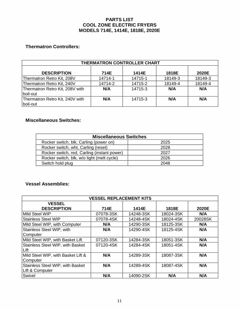
Thermatron Controllers:
THERMATRON CONTROLLER CHART
DESCRIPTION 714E 1414E 1818E 2020EThermatron Retro Kit, 208V 14714-1 14715-1 18149-3 18149-3Thermatron Retro Kit, 240V 14714-2 14715-2 18149-4 18149-4Thermatron Retro Kit, 208V withboil-out
N/A 14715-3 N/A N/A
Thermatron Retro Kit, 240V withboil-out
N/A 14715-3 N/A N/A
Miscellaneous Switches:
Miscellaneous Switches Rocker switch, blk, Carling (power on) 2025 Rocker switch, wht, Carling (reset) 2028 Rocker switch, red, Carling (instant power) 2027 Rocker switch, blk, w/o light (melt cycle) 2026 Switch hold plug 2048
Vessel Assemblies:
VESSEL REPLACEMENT KITSVESSEL
DESCRIPTION 714E 1414E 1818E 2020EMild Steel WIP 07078-3SK 14248-3SK 18024-3SK N/AStainless Steel WIP 07078-4SK 14248-4SK 18024-4SK 20028SKMild Steel WIP, with Computer N/A 14290-3SK 18125-3SK N/AStainless Steel WIP, withComputer
N/A 14290-4SK 18125-4SK N/A
Mild Steel WIP, with Basket Lift 07120-3SK 14284-3SK 18051-3SK N/AStainless Steel WIP, with BasketLift
07120-4SK 14284-4SK 18051-4SK N/A
Mild Steel WIP, with Basket Lift &Computer
N/A 14289-3SK 18087-3SK N/A
Stainless Steel WIP, with BasketLift & Computer
N/A 14289-4SK 18087-4SK N/A
Swivel N/A 14090-2SK N/A N/A

12
9. FACTORY SERVICE & PARTS ORDERING
SERVICE PROBLEMS:
Call the number on the cover of this booklet for the location of your nearest Maintenance& Repair Center or contact the factory direct. Always give the model and serial number ofyour fryer.
ORDERING PARTS:
Customers may order parts directly from their local Authorized Parts Distributor. For thisaddress and phone number, contact your Maintenance & Repair Center or call the factory.Factory address and phone numbers are on the cover of this booklet.

13
10. SPECIFICATIONS
DepthWorkingHeight
Height
Width
SPECIFICATIONS:
MODEL MIN/MAXOil Cap.
SIZE (MM)
Width Depth Height Wrk. Hgt.
DrainValve
DrainValveHeight
FryingArea
Shippinglbs/cu.ft.
714E 25-28 lbs 7-3/4" (197) 29-1/4"(1143)
45" (1143) 35" (889) 1" 20" 6-3/4x14" 115/15
1414E 40-55 lbs 15-1/2"(394)
29-1/4"(1143)
45" (1143) 35" (889) 1-1/4" 20" 14"x14" 153/15
1818E 70-85 lbs 20" (508) 33" (838) 45" (1143) 35" (889) 1-1/4" 20" 18"x18" 190/282020E 95-110 lbs 21" (533) 33" (838) 45" (1143) 35" (889) 1-1/4" 20" 20"x20" 200/35
POWER REQUIREMENTS:
MODEL INPUT SINGLE PHASE THREE PHASE
714E 8 KW 208V/60Hz/1PH-38.5A 240V/60Hz/1ph-33.3A N/A N/A1414E 18 KW 208V/60Hz/1PH-86.5A 240V/60Hz/1ph-75.0A 208V/60Hz/3ph-50.0A 240V/60Hz/3ph-43.3A1818E 13,5 KW
18 KW208V/60Hz/1PH-65.0A208V/60Hz/1PH-86.5A
240V/60Hz/1ph-56.3A240V/60Hz/1ph-75.0A
208V/60Hz/3ph-37.5A208V/60Hz/3ph-50.0A
240V/60Hz/3ph-32.5A240V/60Hz/3ph-43.3A
2020E 13,5 KW18 KW
208V/60Hz/1PH-65.0A208V/60Hz/1PH-86.5A
240V/60Hz/1ph-56.3A240V/60Hz/1ph-75.0A
208V/60Hz/3ph-37.5A208V/60Hz/3ph-50.0A
240V/60Hz/3ph-32.5A240V/60Hz/3ph-43.3A
STANDARD FEATURES:
3 Mild steel fry vessel3 Stainless steel front, door, and sides3 Stainless steel basket hanger & 2 1/2 size baskets (714E - 1 basket)3 Cool zone fry vessel construction3 Thermatron solid state controls3 Easily removable door for cleaning or servicing3 6" adjustable steel legs

14
11. WIRING DIAGRAMS

15

16
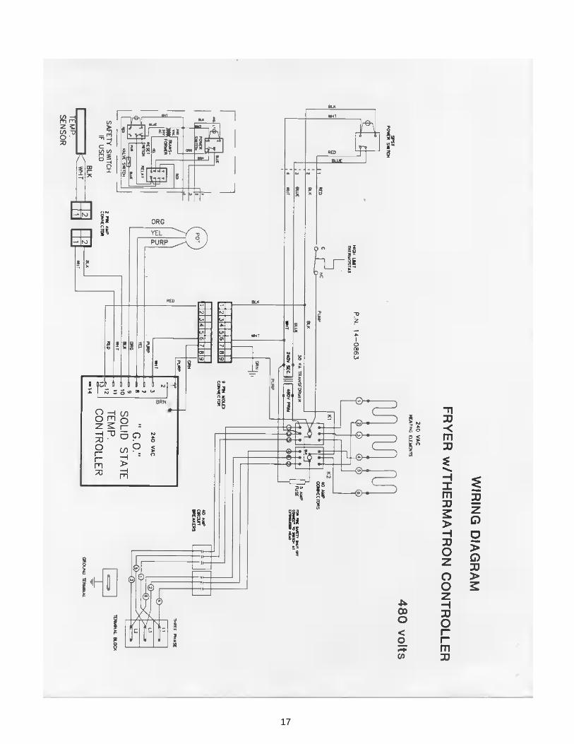
17

18
LIMITED WARRANTY
1. WARRANTY AND REMEDY
A. NEW EQUIPMENT. Dean Industries warrants its fryers and equipment to be free from defects in materialsand workmanship. Dean's obligation under this warranty shall be limited to replacing or repairing, at theCompany's discretion, without charge to Buyer any part found to be defective, and expenses incurred forfreight and materials for the installation or repair of such part for a period of one (1) year from the date ofBuyer's purchase, initial start-up of the equipment or eighteen (18) months from the date of shipment from thefactory, whichever is sooner. The following conditions must be met to exercise this warranty
1. Buyer must promptly notify the Company of any such defect(s) in writing;2. Notification must occur during the first (1st) year from the date of purchase or initial equipment start-
up, or eighteen (18) months from the date of shipment from the factory, whichever is sooner;3. Warranty work must be performed by a factory authorized service company;4. Factory authorization must be obtained before work is performed (non-stocking Maintenance &
Repair Centers);5. Factory pays freight one way only'6. Factory pays straight time service rates only.
Dean's obligation to pay for labor shall only be provided to buyers within the continental United States, Alaska,Hawaii and Canada. Dean's one (1) year labor warranty includes authorized service agent travel time up tothree (3) hours and mileage up to 100 miles. Any travel time or mileage in excess of the above shall beBuyer's responsibility. The Factory shall make no allowance for repairs or alterations made by Buyer unlessmade with Factory's prior written consent.
B. REPLACEMENT PARTS. Any replacement part, except lamps and fuses, which proves to be defective inmaterial or workmanship within ninety (90) days from the date of replacement part installation will be repairedor replaced without charge, FOB Authorized Distributor. This warranty covers only the repair or replacement ofthe defective part and does not include any labor charges for the removal and installation of any part or travelor other expense incidental to the repair or replacement of a part. Dean will not be responsible for problemsfound to be caused by use of a non-OEM part or replacement of a defective part with other than a factory OEMpart.
2. LIMITATION OF COMPANY'S LIABILITY. This warranty does not cover any defect due to, or resulting fromhandling, improper installation, abuse, misuse, or harsh chemical action, nor shall it extend to any unit from whichthe serial number has been removed or altered, or modifications made by unauthorized service personnel or damageby flood, fire or other acts of God. Adjustment such as calibrations, leveling, tightening of fasteners or plumbing orelectrical connections normally associated with original installation are the responsibility of the dealer, theowner/user, or the installer and not that of the Company.
The Company shall not be liable, directly or indirectly, under any circumstances for consequential or individualdamages, including, but not limited to: (i) any loss of business or profits; and (ii) labor, material or other changes,claims, losses or damages incurred or suffered from, in connection with or in consequence of a claimed defectiveproduct or parts or the working upon, alterations, or repair of any such claimed defective product or parts by personsor firms other than the Company.
3. LIMITATION OF ACTIONS. Any action for any loss or damage with respect to the good or services covered herein must be commenced by Buyer within one (1) year after Buyer's cause of action has occurred.
4. THIS WARRANTY APPLIES TO ORIGINAL BUYER ONLY AND IS NOT TRANSFERABLE.
5. INFORMATION ON WARRANTY PROCEDURES. For further information on warranty procedures, pleasecontact Dean Industries at (310) 353-5000; Toll Free (800) 995-1210.
6. FRY VESSEL WARRANTYSM35 1 Year Mild Steel
5 Year Stainless Steel ProratedFlat Bottom 3 Year ProratedAll other Cool Zone Fryers 10 Year Stainless Steel

Dean, 8700 Line Avenue, Shreveport, Louisiana 71135
TEL 1-318-865-1711 FAX (Parts) 1-318-219-7140 (Tech Support) 1-318-219-7135
Price: $6.00PRINTED IN THE UNITED STATES
SERVICE HOTLINE1-800-551-8633 819-5867