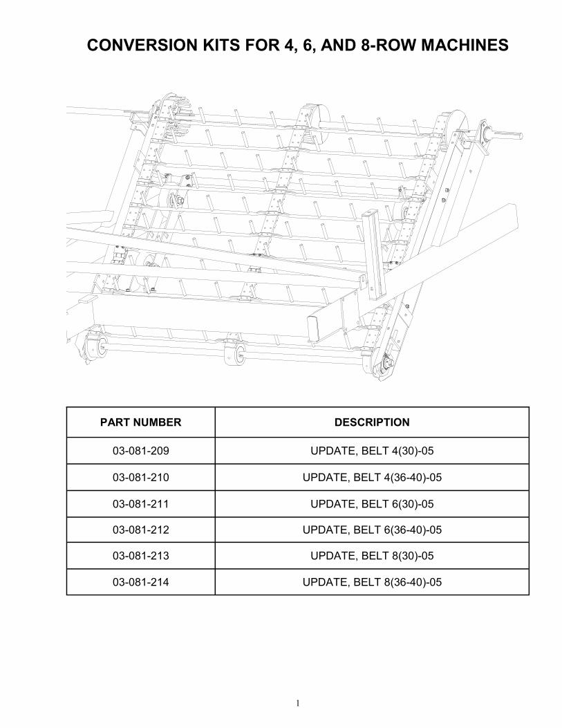
conversion kits · conversion kits for 4, 6, and 8-row machines . 2 rattler frame with chains (bars...
TRANSCRIPT
2, 4, 6, & 8-ROW
CONVERSION KITS
(FROM CHAINS TO BELTS)
03-SERIES
THIS MANUAL TO ACCOMPANY MACHINE
PART NO. 03-OM-KIT
PRINTING DATE: JULY 2010
OPERATOR MANUAL
WARRANTY POLICY KELLEY MANUFACTURING COMPANY (KMC) warrants that all goods sold to the original purchaser of any KMC product shall be free of any defects in material and workmanship if used under normal operating conditions. The warranty period begins on the date of purchase by the retail customer and ends twelve (12) months thereafter. KMC’s sole responsibility is to repair and/or replace the defective part or parts at no cost to purchaser. This remedy is the SOLE AND EXCLUSIVE REMEDY of purchaser.
The purchaser must fill out and return the warranty registration form found in the front of the operator’s manual. Failure to return the warranty registration form within 30 days shall result in the goods being sold “AS IS”, and all warranties shall be excluded.
This warranty shall not apply to those items that are by nature worn in normal service, including but not limited to belts, springs, teeth, chains, etc. Items such as tires, tubes, and gearboxes and all other items warranted by the original manufacturer are warranted only to the extent of their individual manufacturer warranty, and KMC is not warranting any of said items. All warranty claims must be made through a KMC licensed dealer, and a warranty form request must be submitted to KMC within 30 days of failure or the warranty provision shall be unenforceable against KMC.
No agent or person has authority to change or add to this warranty as written.
THE ABOVE IS THE ONLY WARRANTY MADE BY KMC AND IS MADE EXPRESSLY IN LIEU OF ALL OTHER WARRANTIES, EXPRESSED OR IMPLIED. KMC MAKES NO WARRANTY OF MERCHANTABILITY AS TO ANY GOODS MANUFACTURED BY KMC AND FURTHER, KMC DOES NOT WARRANT ANY SUCH GOODS AS SUITABLE FOR ANY PARTICULAR PUR-POSE TO THE RETAIL CUSTOMER. THE SUITABILITY OF GOODS FOR ANY PURPOSE PARTICULAR TO THE CUSTOMER IS FOR THE CUSTOMER, IN HIS SOLE JUDGEMENT, TO DETERMINE. KMC FURTHER MAKES NO WARRANTIES WITH RESPECT TO ITS MANUFACTURED GOODS THAT WOULD NORMALLY BE DISCLOSED BY AN EXAMINATION. THIS IS THE FULL AND FINAL EXPRESSION OF ALL WARRANTY LIABILITY OF KMC. NO OTHER WARRANTY, EITHER EXPRESSED OR IMPLIED, SHALL BE ENFORCEABLE AGAINST KMC.
Kelley Manufacturing Co. 80 Vernon Drive / Zip 31794
P.O. Drawer 1467 / Zip 31793 Tifton GA
1
PART NUMBER DESCRIPTION
03-081-209 UPDATE, BELT 4(30)-05
03-081-210 UPDATE, BELT 4(36-40)-05
03-081-211 UPDATE, BELT 6(30)-05
03-081-212 UPDATE, BELT 6(36-40)-05
03-081-213 UPDATE, BELT 8(30)-05
03-081-214 UPDATE, BELT 8(36-40)-05
CONVERSION KITS FOR 4, 6, AND 8-ROW MACHINES
2
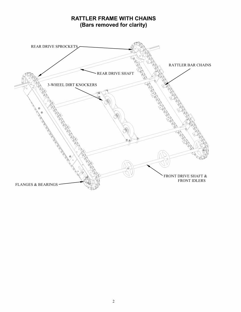
RATTLER FRAME WITH CHAINS (Bars removed for clarity)
REAR DRIVE SPROCKETS
REAR DRIVE SHAFT
3-WHEEL DIRT KNOCKERS
RATTLER BAR CHAINS
FRONT DRIVE SHAFT &
FRONT IDLERS FLANGES & BEARINGS
3
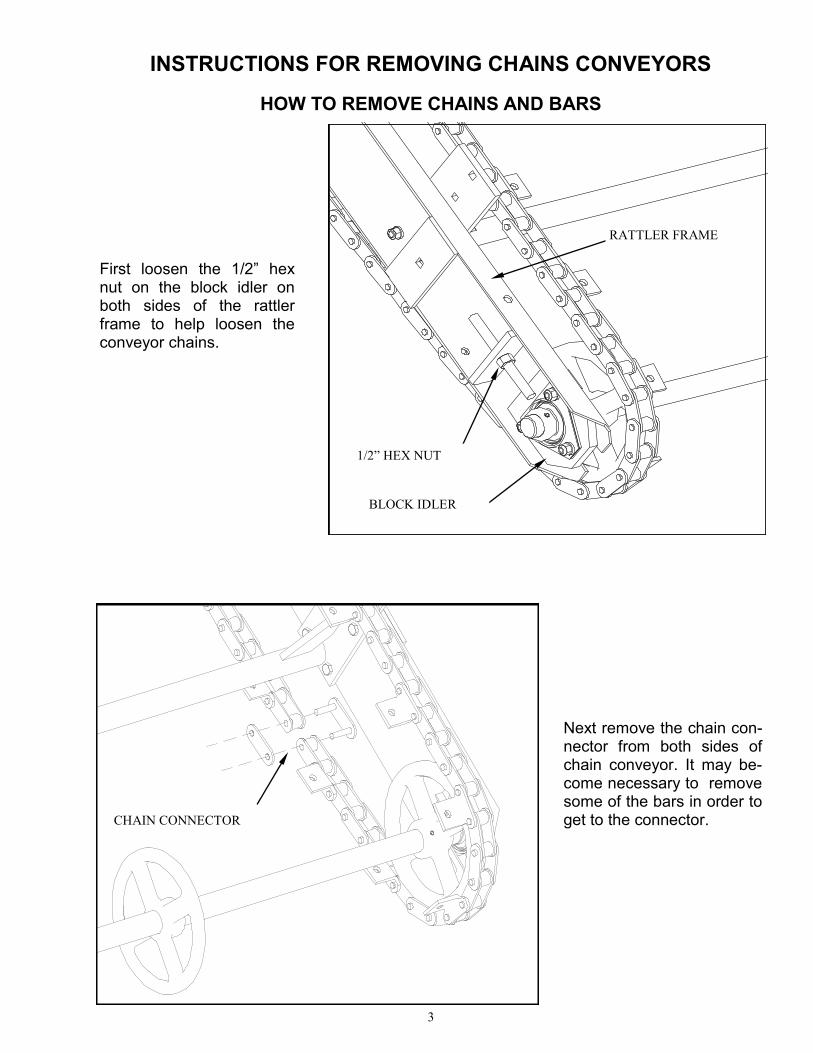
Next remove the chain con-nector from both sides of chain conveyor. It may be-come necessary to remove some of the bars in order to get to the connector.
HOW TO REMOVE CHAINS AND BARS
INSTRUCTIONS FOR REMOVING CHAINS CONVEYORS
First loosen the 1/2” hex nut on the block idler on both sides of the rattler frame to help loosen the conveyor chains.
1/2” HEX NUT
RATTLER FRAME
BLOCK IDLER
CHAIN CONNECTOR
4
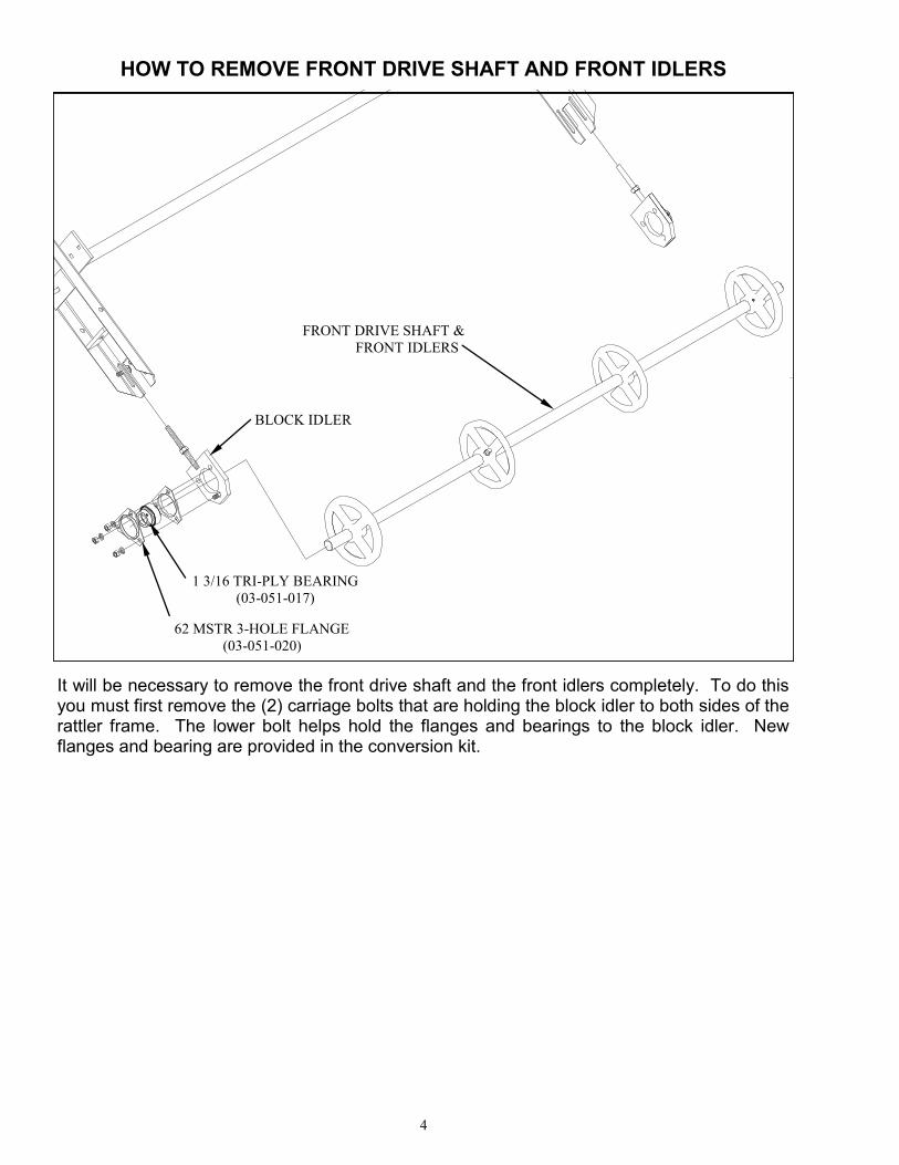
It will be necessary to remove the front drive shaft and the front idlers completely. To do this you must first remove the (2) carriage bolts that are holding the block idler to both sides of the rattler frame. The lower bolt helps hold the flanges and bearings to the block idler. New flanges and bearing are provided in the conversion kit.
DRAWN BY GROSS LENGTHMATERIAL PART NO.
sharon7/23/2010
FRONT DRIVE SHAFT &
FRONT IDLERS
BLOCK IDLER
1 3/16 TRI-PLY BEARING
(03-051-017)
62 MSTR 3-HOLE FLANGE
(03-051-020)
HOW TO REMOVE FRONT DRIVE SHAFT AND FRONT IDLERS
5
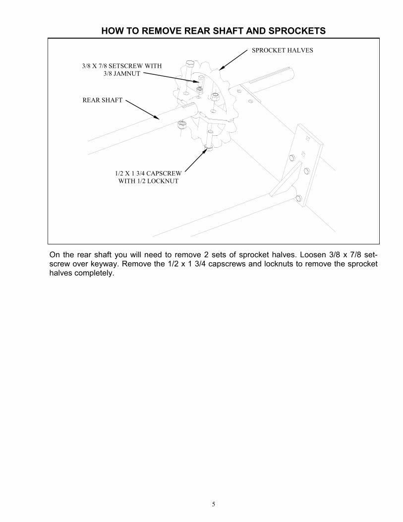
HOW TO REMOVE REAR SHAFT AND SPROCKETS
REAR SHAFT
SPROCKET HALVES
1/2 X 1 3/4 CAPSCREW
WITH 1/2 LOCKNUT
3/8 X 7/8 SETSCREW WITH
3/8 JAMNUT
On the rear shaft you will need to remove 2 sets of sprocket halves. Loosen 3/8 x 7/8 set-screw over keyway. Remove the 1/2 x 1 3/4 capscrews and locknuts to remove the sprocket halves completely.
6
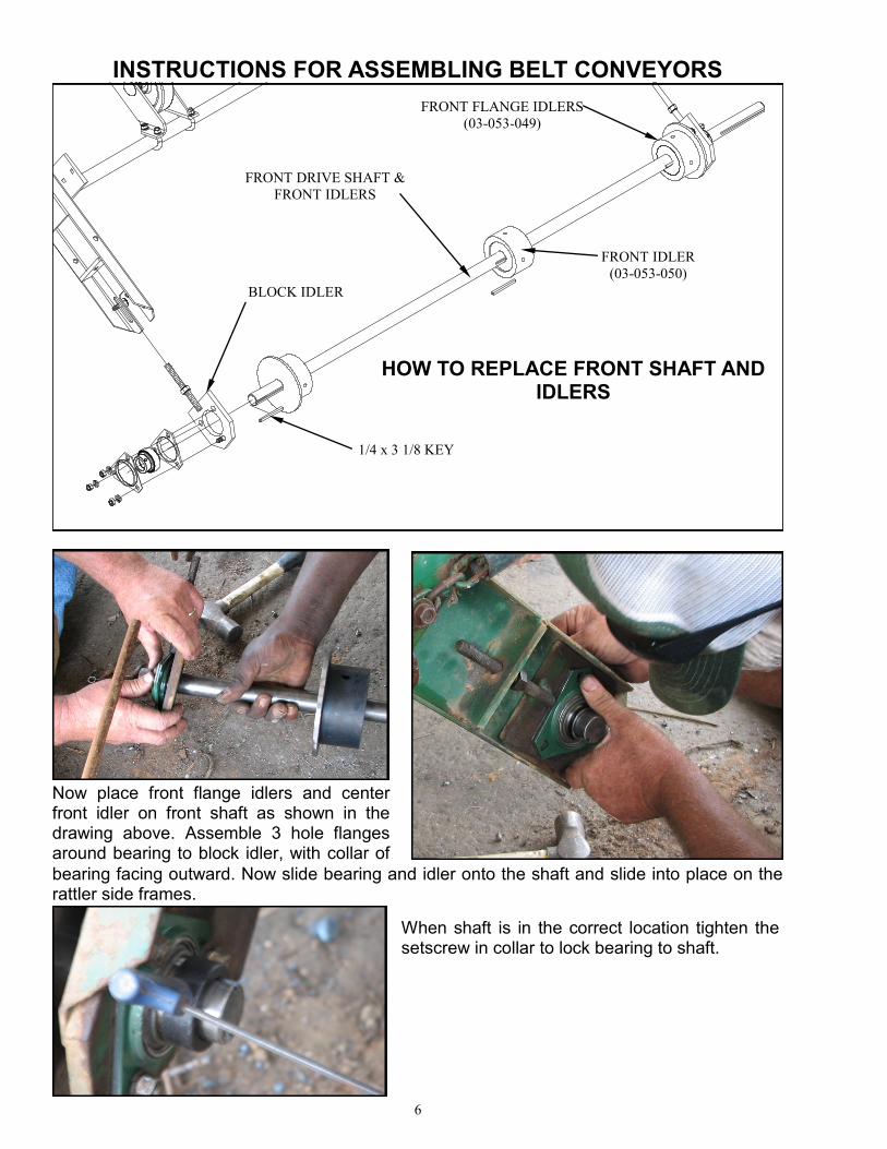
INSTRUCTIONS FOR ASSEMBLING BELT CONVEYORS
Now place front flange idlers and center front idler on front shaft as shown in the drawing above. Assemble 3 hole flanges around bearing to block idler, with collar of
FRONT DRIVE SHAFT &
FRONT IDLERS
1/4 x 3 1/8 KEY
HOW TO REPLACE FRONT SHAFT AND IDLERS
FRONT FLANGE IDLERS
(03-053-049)
FRONT IDLER
(03-053-050)
BLOCK IDLER
bearing facing outward. Now slide bearing and idler onto the shaft and slide into place on the rattler side frames.
When shaft is in the correct location tighten the setscrew in collar to lock bearing to shaft.
7
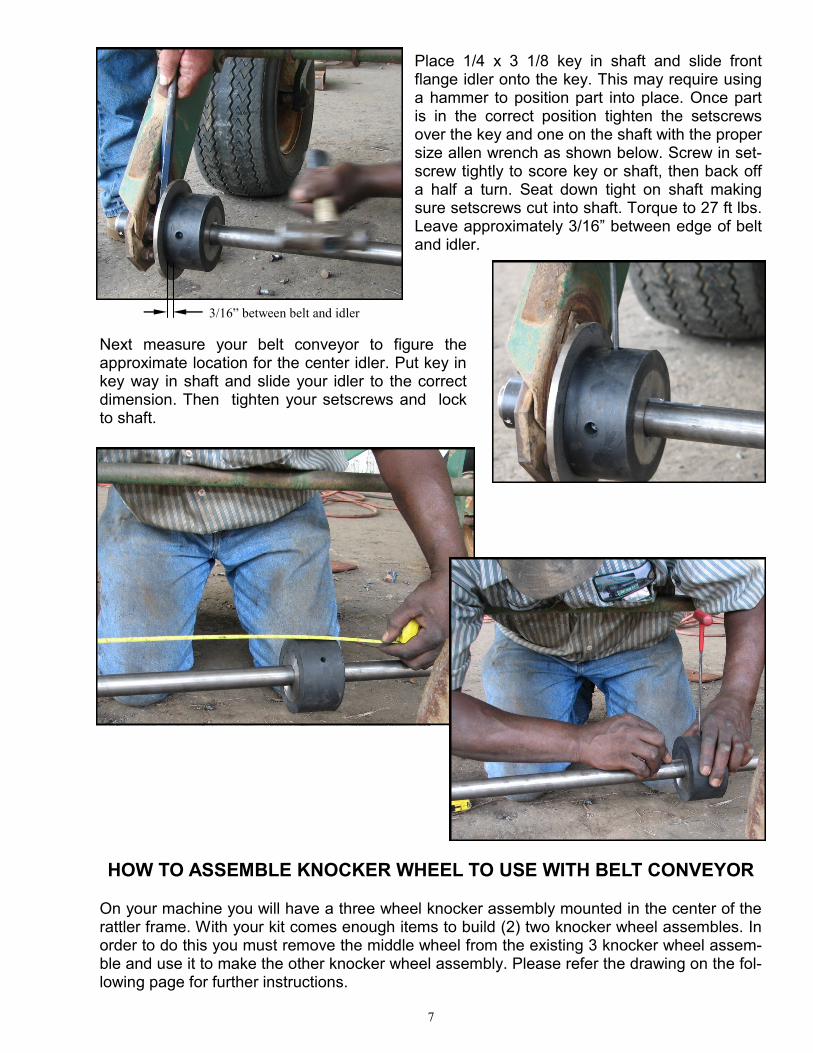
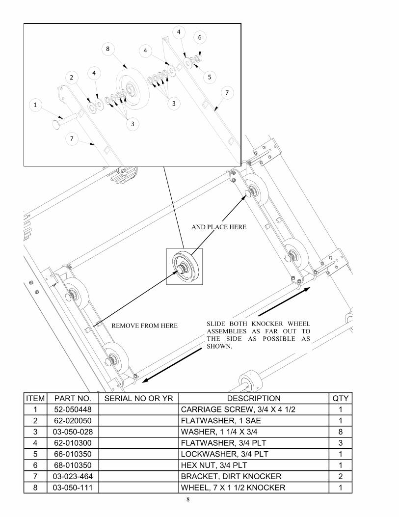
HOW TO ASSEMBLE KNOCKER WHEEL TO USE WITH BELT CONVEYOR
On your machine you will have a three wheel knocker assembly mounted in the center of the rattler frame. With your kit comes enough items to build (2) two knocker wheel assembles. In order to do this you must remove the middle wheel from the existing 3 knocker wheel assem-ble and use it to make the other knocker wheel assembly. Please refer the drawing on the fol-lowing page for further instructions.
Next measure your belt conveyor to figure the approximate location for the center idler. Put key in key way in shaft and slide your idler to the correct dimension. Then tighten your setscrews and lock to shaft.
Place 1/4 x 3 1/8 key in shaft and slide front flange idler onto the key. This may require using a hammer to position part into place. Once part is in the correct position tighten the setscrews over the key and one on the shaft with the proper size allen wrench as shown below. Screw in set-screw tightly to score key or shaft, then back off a half a turn. Seat down tight on shaft making sure setscrews cut into shaft. Torque to 27 ft lbs. Leave approximately 3/16” between edge of belt and idler.
3/16” between belt and idler
8
REMOVE FROM HERE
ITEM PART NO. SERIAL NO OR YR DESCRIPTION QTY
1 52-050448 CARRIAGE SCREW, 3/4 X 4 1/2 1
2 62-020050 FLATWASHER, 1 SAE 1
3 03-050-028 WASHER, 1 1/4 X 3/4 8
4 62-010300 FLATWASHER, 3/4 PLT 3
5 66-010350 LOCKWASHER, 3/4 PLT 1
6 68-010350 HEX NUT, 3/4 PLT 1
7 03-023-464 BRACKET, DIRT KNOCKER 2
8 03-050-111 WHEEL, 7 X 1 1/2 KNOCKER 1
1
24
3
8
4
4
3
7
7
5
6
TIFTON, GA.DRAWN BY
MATERIAL
PART NAME
UNLESS NOTED
1
1/32
0.010
DATE
OTHERWISE
ANGULAR
FRACTIONAL
DECIMAL
GROSS LENGTHMATERIAL PART NO.
sharon7/22/2010
AND PLACE HERE
SLIDE BOTH KNOCKER WHEEL
ASSEMBLIES AS FAR OUT TO
THE SIDE AS POSSIBLE AS
SHOWN.
9
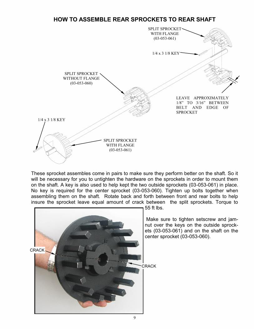
HOW TO ASSEMBLE REAR SPROCKETS TO REAR SHAFT
These sprocket assembles come in pairs to make sure they perform better on the shaft. So it will be necessary for you to untighten the hardware on the sprockets in order to mount them on the shaft. A key is also used to help kept the two outside sprockets (03-053-061) in place. No key is required for the center sprocket (03-053-060). Tighten up bolts together when assembling them on the shaft. Rotate back and forth between front and rear bolts to help insure the sprocket leave equal amount of crack between the split sprockets. Torque to
55 ft lbs. Make sure to tighten setscrew and jam-nut over the keys on the outside sprock-ets (03-053-061) and on the shaft on the center sprocket (03-053-060).
SPLIT SPROCKET
WITH FLANGE
(03-053-061)
SPLIT SPROCKET
WITH FLANGE
(03-053-061)
SPLIT SPROCKET
WITHOUT FLANGE
(03-053-060)
1/4 x 3 1/8 KEY
1/4 x 3 1/8 KEY
LEAVE APPROXIMATELY
1/8” TO 3/16” BETWEEN
BELT AND EDGE OF
SPROCKET
CRACK
CRACK
10
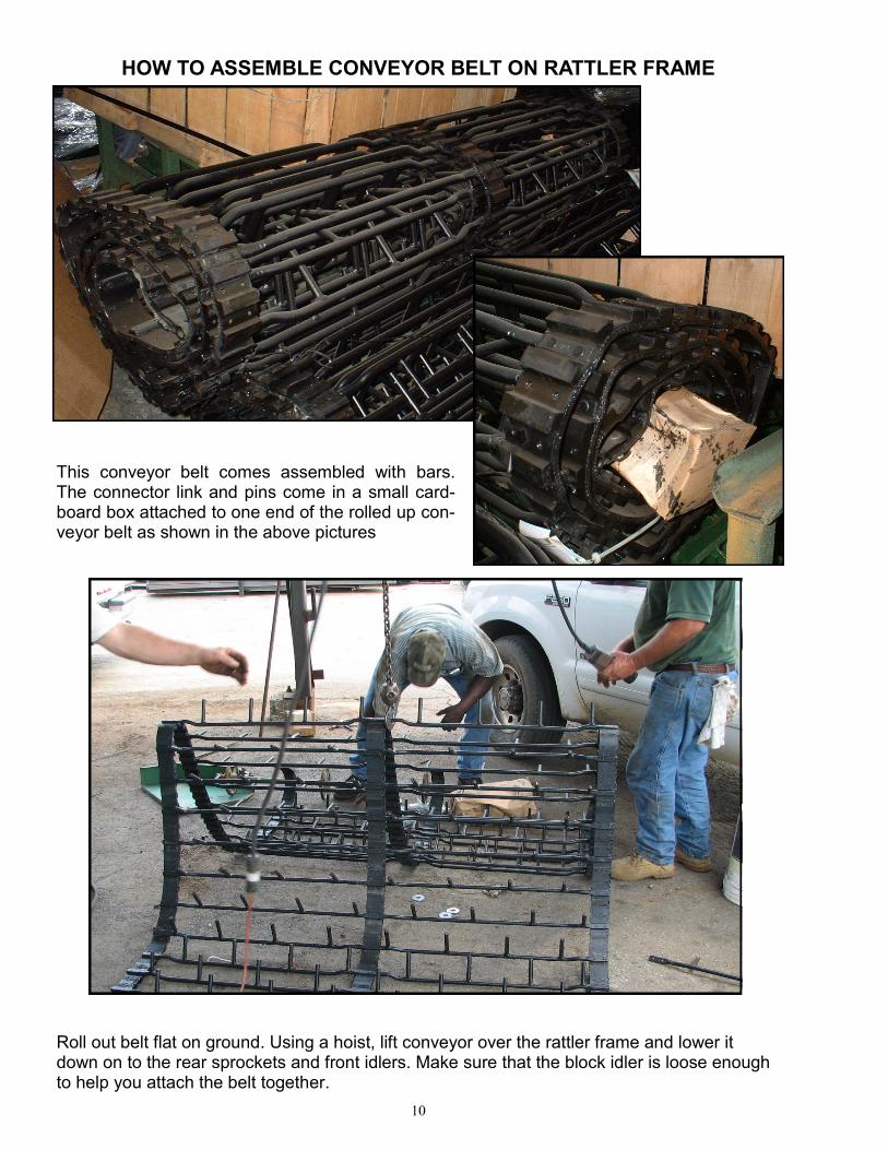
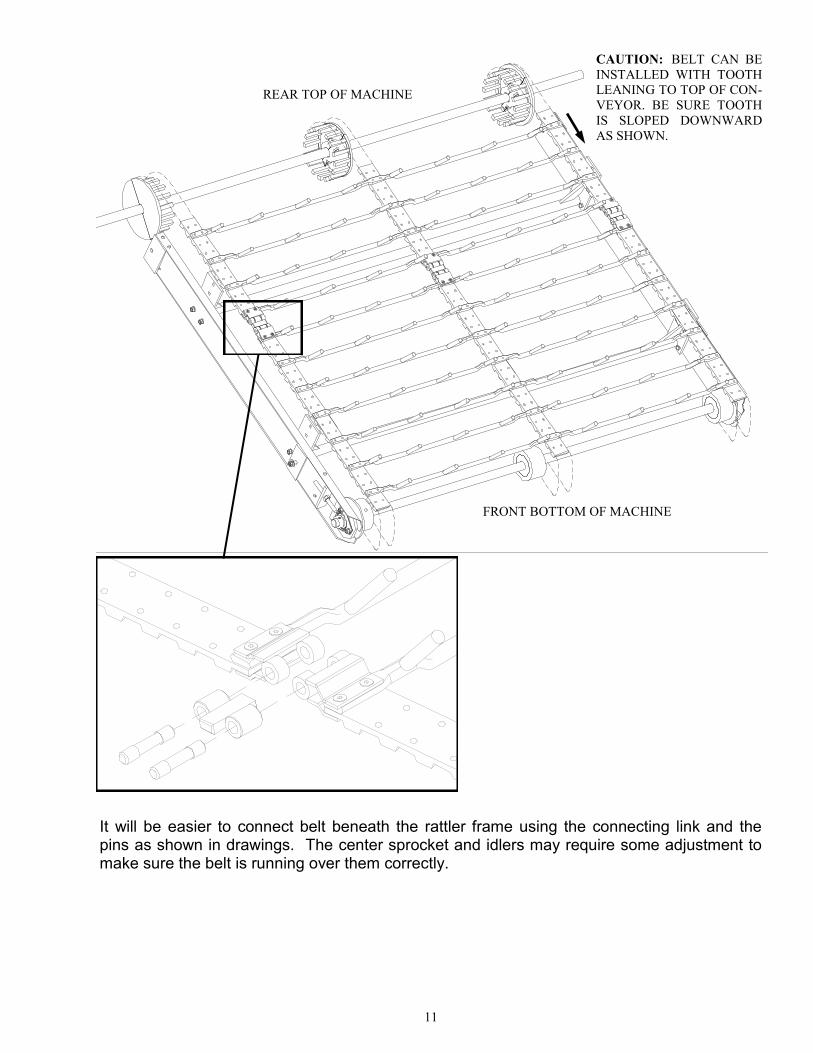
HOW TO ASSEMBLE CONVEYOR BELT ON RATTLER FRAME
Roll out belt flat on ground. Using a hoist, lift conveyor over the rattler frame and lower it down on to the rear sprockets and front idlers. Make sure that the block idler is loose enough to help you attach the belt together.
This conveyor belt comes assembled with bars. The connector link and pins come in a small card-board box attached to one end of the rolled up con-veyor belt as shown in the above pictures
11
TIFTON, GA.DRAWN BY
WEIGHT
MATERIAL
PART NAME
PART NUMBER
UNLESS NOTED
1
1/32
0.010
DATE
OTHERWISE
TOLERANCES
ANGULAR
FRACTIONAL
DECIMAL
SHEET
1 of 1
GROSS LENGTHMATERIAL PART NO.
sharon7/28/2010
3B BELT ASSEMBLY
ITEM
1
2
3
4
5
6
It will be easier to connect belt beneath the rattler frame using the connecting link and the pins as shown in drawings. The center sprocket and idlers may require some adjustment to make sure the belt is running over them correctly.
CAUTION: BELT CAN BE
INSTALLED WITH TOOTH
LEANING TO TOP OF CON-
VEYOR. BE SURE TOOTH
IS SLOPED DOWNWARD
AS SHOWN.
REAR TOP OF MACHINE
FRONT BOTTOM OF MACHINE
12
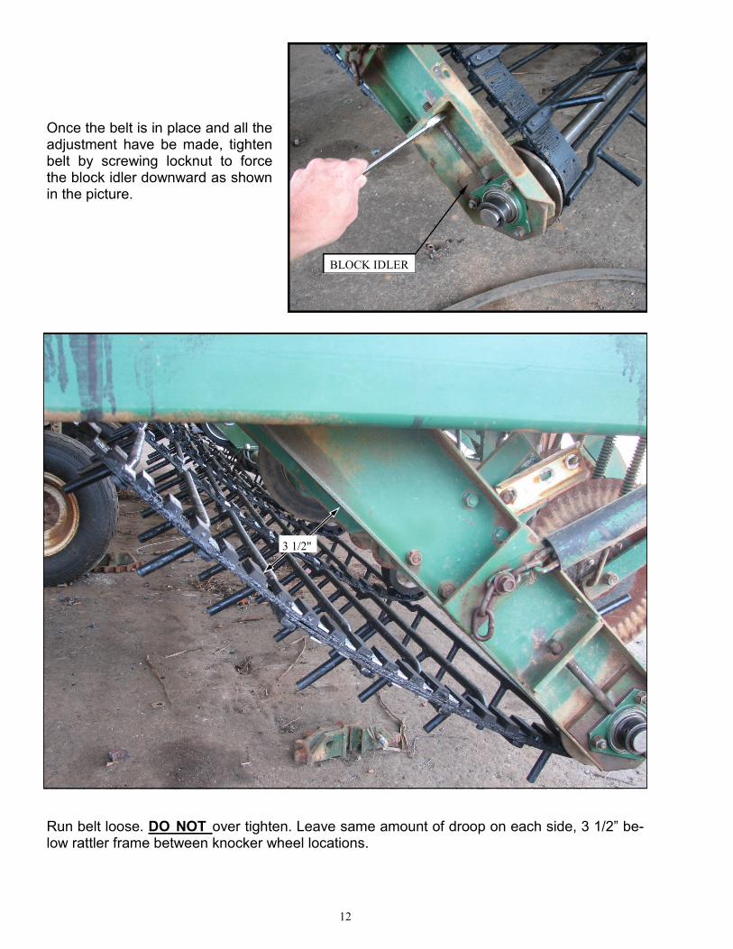
Once the belt is in place and all the adjustment have be made, tighten belt by screwing locknut to force the block idler downward as shown in the picture.
BLOCK IDLER
Run belt loose. DO NOT over tighten. Leave same amount of droop on each side, 3 1/2” be-low rattler frame between knocker wheel locations.
KNOCKER WHEEL ASSEMBLY
RATTLER FRAME
3 1/2"
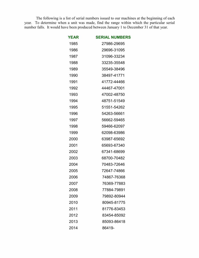
The following is a list of serial numbers issued to our machines at the beginning of each
year. To determine when a unit was made, find the range within which the particular serial
number falls. It would have been produced between January 1 to December 31 of that year.
YEAR SERIAL NUMBERS
1985 27986-29695
1986 29696-31095
1987 31096-33234
1988 33235-35548
1989 35549-38496
1990 38497-41771
1991 41772-44466
1992 44467-47001
1993 47002-48750
1994 48751-51549
1995 51551-54262
1996 54263-56661
1997 56662-59465
1998 59466-62097
1999 62098-63986
2000 63987-65692
2001 65693-67340
2002 67341-68699
2003 68700-70482
2004 70483-72646
2005 72647-74866
2006 74867-76368
2007 76369-77883
2008 77884-79891
2009 79892-80944
2010 80945-81775
2011 81776-83453
2012 83454-85092
2013 85093-86418
2014 86419-

DEPENDABLE EQUIPMENT FOR PROGRESSIVE FARMING
KELLEY MANUFACTURING CO.
80 Vernon Drive / Zip 31794 P.O. Drawer 1467 / Zip 31793
Tifton, GA
Tel: 229-382-9393 Toll Free: 1-800-444-5449
Fax: 229-382-5259 Email Address: [email protected]
Visit us at www.kelleymfg.com
MADE IN AMERICA