313840p, manual, datatrak kits instructions/parts, … kits 313840p 3 datatrak kits conversion kits...
TRANSCRIPT
Kit Instructions/Parts
DataTrak® Kits 313840PEN
For providing pump diagnostics and material usage information for diaphragm pumps.
Conversion Kits - DataTrak with Pulse Count and Runaway Protection
Conversion Kits - DataTrak with Pulse Count
Replacement Parts Kits
See pages 2 and 3 for model and agency approvals information.
Important Safety InstructionsRead all warnings and instructions in appropriate product manuals. Save all instructions.
Model 24B777 shown
ti14052a
Contents
2 313840P
ContentsContents . . . . . . . . . . . . . . . . . . . . . . . . . . . . . . . . . . 2Related Manuals . . . . . . . . . . . . . . . . . . . . . . . . . . . 2DataTrak Kits . . . . . . . . . . . . . . . . . . . . . . . . . . . . . . 3Installation . . . . . . . . . . . . . . . . . . . . . . . . . . . . . . . . 4
Prepare to Install . . . . . . . . . . . . . . . . . . . . . . . . . 4Install the Kit . . . . . . . . . . . . . . . . . . . . . . . . . . . . 4Check DataTrak Operation . . . . . . . . . . . . . . . . . 5
DataTrak Controls and Indicators . . . . . . . . . . . . . 6
DataTrak Operation . . . . . . . . . . . . . . . . . . . . . . . . . 7Setup Mode . . . . . . . . . . . . . . . . . . . . . . . . . . . . . 7Run Mode . . . . . . . . . . . . . . . . . . . . . . . . . . . . . . 7Calibration Procedure . . . . . . . . . . . . . . . . . . . . . 9
Parts . . . . . . . . . . . . . . . . . . . . . . . . . . . . . . . . . . . . 14Graco Standard Warranty . . . . . . . . . . . . . . . . . . . 20Graco Information . . . . . . . . . . . . . . . . . . . . . . . . . 20
Related ManualsPump Operation Repair/Parts
Husky 1050 312877 313435
Husky 15120 3A2888 3A2889
Husky 2200 3A2578 3A2714
Husky 3300 3A0410 3A0411
Endura-Flo 4D150 and 4D350 333015
DataTrak™ includes agency approvals listed below.
2575II 1 G
Ex ia IIA T3 GaITS13ATEX27862X9902471
Class I, Div. 1,Group D T3A
DataTrak Kits
313840P 3
DataTrak Kits
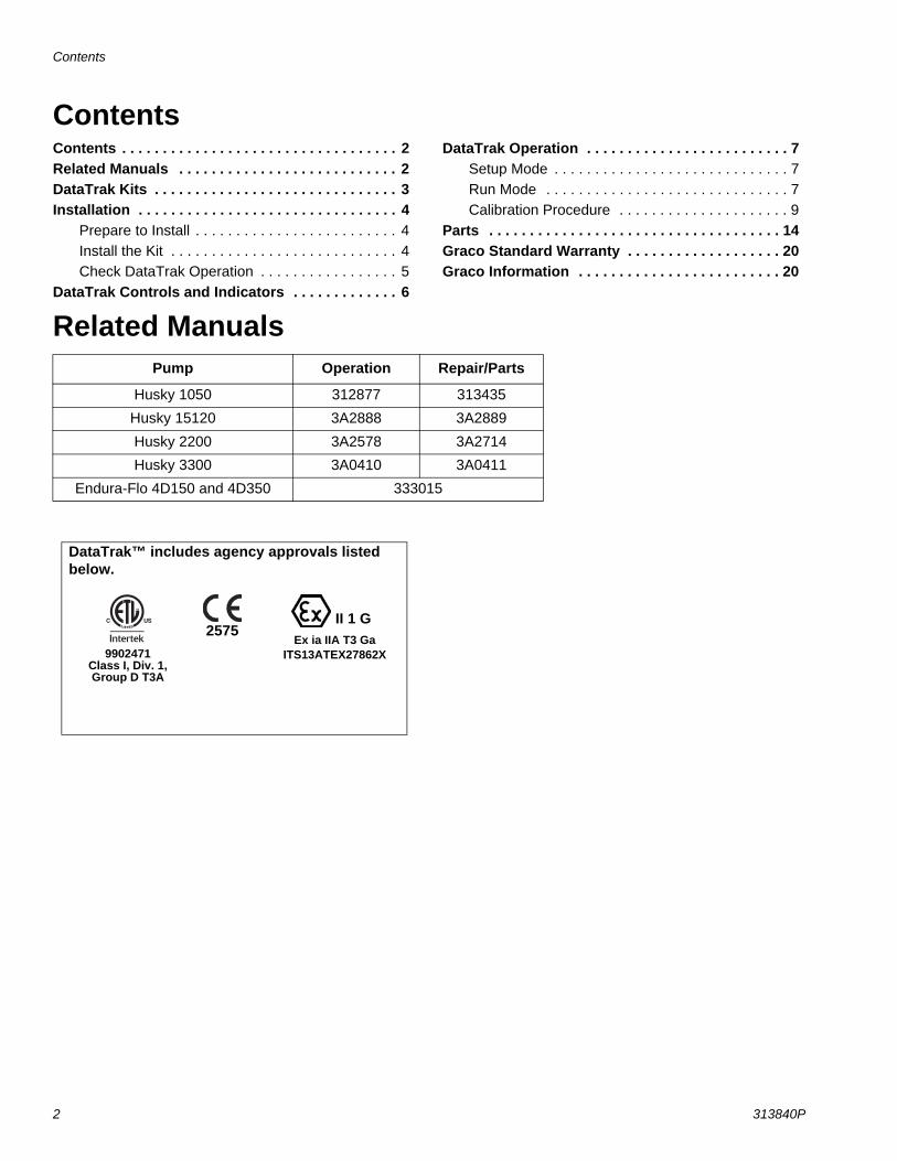
Conversion KitsUse to add data monitoring capabilities to an existing pump.
* Kit includes replacement air valve compatible with solenoid.
Replacement Part KitsAluminum
Polypropylene and Conductive Polypropylene
Endura-Flo 4D150
Endura-Flo 4D350
Husky 1050
Husky 15120
Husky 2200
Husky 3300
Diaphragm Pump Material
Data Monitoring
Pulse Count and Runaway Protection
Pulse Count
24Y304 24Y306 24B777 24K861Aluminum
*
24B795 24B795
24B784 24B784 24V233 24K862Polypropylene
*
24B794 24B794 24B794 24B794
24B793 ConductivePolypropylene
*
24B794
Endura-Flo 4D150
Endura-Flo 4D350
Husky 1050A
Husky 3300A Description
17H320 17H321 24B772 24K864Solenoid/Reed Switch Assembly
(pulse count and runaway protection)
24B798 24B798Reed Switch Assembly
(pulse count only)
Husky 1050P or 1050C
Husky 15120P
Husky 2200P
Husky 3300P Description
24B771 24B771 24K863 24K863Solenoid/Reed Switch Assembly
(pulse count and runaway protection)
24B796 24B796 24B796 24B796Reed Switch Assembly
(pulse count only)
Installation
4 313840P
Installation
Prepare to Install1. Relieve the pressure. Follow instructions in your
Operation manual.
2. Disconnect the air line to the pump.
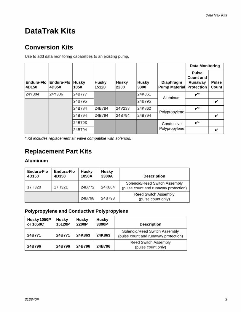
Install the Kit1. Mount the bracket
to the wall. Use approximately 3/8 in. bolts or screws.
2. Install the Data-Trak module (1) on the bracket.
3. Conversion Kits include a new air valve that is com-patible with the solenoid. Remove the old air valve and gasket from the pump, and install the replace-ment air valve and gasket.
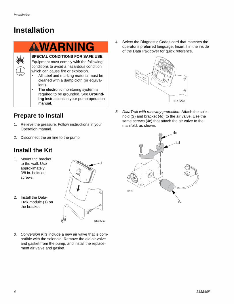
4. Select the Diagnostic Codes card that matches the operator’s preferred language. Insert it in the inside of the DataTrak cover for quick reference.
5. DataTrak with runaway protection: Attach the sole-noid (S) and bracket (4d) to the air valve. Use the same screws (4c) that attach the air valve to the manifold, as shown.
SPECIAL CONDITIONS FOR SAFE USEEquipment must comply with the following conditions to avoid a hazardous condition which can cause fire or explosion.• All label and marking material must be
cleaned with a damp cloth (or equiva-lent).
• The electronic monitoring system is required to be grounded. See Ground-ing instructions in your pump operationmanual.
WARNINGWARNINGWARNINGWARNING
1
ti14055a
ti14223a
S
4d
4c
Installation
313840P 5
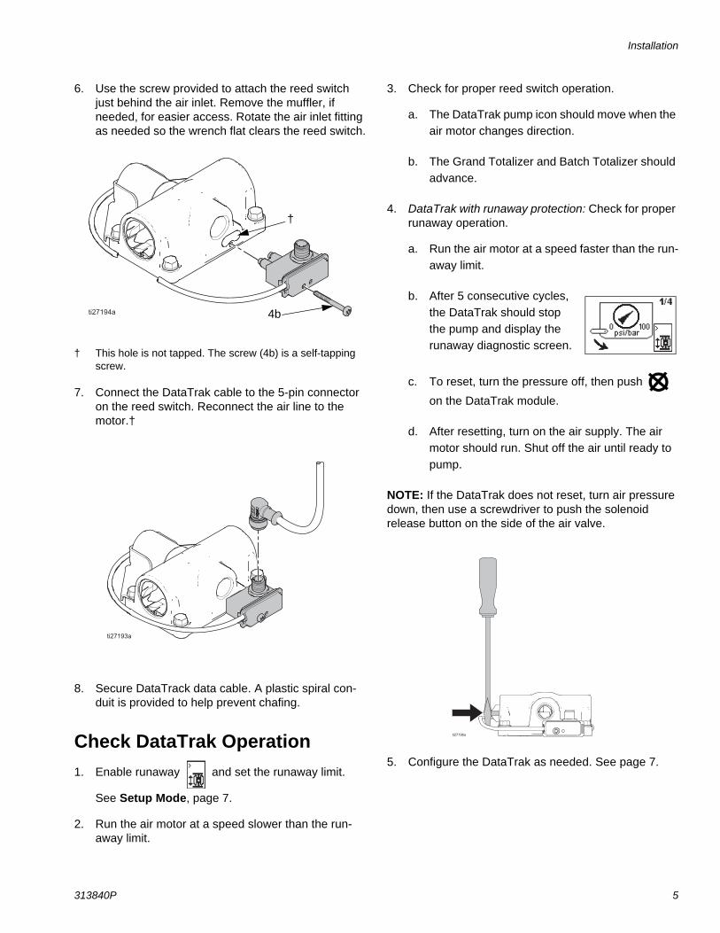
6. Use the screw provided to attach the reed switch just behind the air inlet. Remove the muffler, if needed, for easier access. Rotate the air inlet fitting as needed so the wrench flat clears the reed switch.
† This hole is not tapped. The screw (4b) is a self-tapping screw.
7. Connect the DataTrak cable to the 5-pin connector on the reed switch. Reconnect the air line to the motor.†
8. Secure DataTrack data cable. A plastic spiral con-duit is provided to help prevent chafing.
Check DataTrak Operation1. Enable runaway and set the runaway limit.
See Setup Mode, page 7.
2. Run the air motor at a speed slower than the run-away limit.
3. Check for proper reed switch operation.
a. The DataTrak pump icon should move when the air motor changes direction.
b. The Grand Totalizer and Batch Totalizer should advance.
4. DataTrak with runaway protection: Check for proper runaway operation.
a. Run the air motor at a speed faster than the run-away limit.
b. After 5 consecutive cycles, the DataTrak should stop the pump and display the runaway diagnostic screen.
c. To reset, turn the pressure off, then push
on the DataTrak module.
d. After resetting, turn on the air supply. The air motor should run. Shut off the air until ready to pump.
NOTE: If the DataTrak does not reset, turn air pressure down, then use a screwdriver to push the solenoid release button on the side of the air valve.
5. Configure the DataTrak as needed. See page 7.
†
4b
DataTrak Controls and Indicators
6 313840P
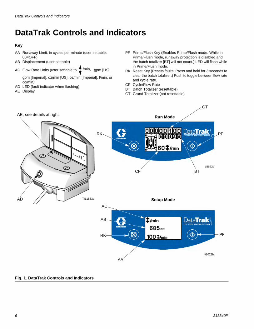
DataTrak Controls and IndicatorsKey
AA Runaway Limit, in cycles per minute (user settable; 00=OFF)
AB Displacement (user settable)
AC Flow Rate Units (user settable to gpm [US],
gpm [Imperial], oz/min [US], oz/min [Imperial], l/min, or cc/min)
AD LED (fault indicator when flashing)AE Display
PF Prime/Flush Key (Enables Prime/Flush mode. While in Prime/Flush mode, runaway protection is disabled and the batch totalizer [BT] will not count.) LED will flash while in Prime/Flush mode.
RK Reset Key (Resets faults. Press and hold for 3 seconds to clear the batch totalizer.) Push to toggle between flow rate and cycle rate.
CF Cycle/Flow RateBT Batch Totalizer (resettable)GT Grand Totalizer (not resettable)
/min,
Fig. 1. DataTrak Controls and Indicators
AD
AE, see details at right
CF BT
GT
AC
AA
PFRK
AB
Run Mode
Setup ModeTI11883a
RK PF
ti8622b
ti8623b
DataTrak Operation
313840P 7
DataTrak OperationNOTE: The display (AE) will turn off after 1 minute to save battery life. Press any key to wake up the display.NOTE: For Husky pumps, DataTrak is factory set to 685 cc/cycle. This setting is accurate for pumping water at a medium speed on a Husky 1050 pump (approximately 20 gpm). For Endura-Flo pumps, DataTrak is factory set to the displacement of the pump. The DataTrak can be calibrated for use with a different Husky or Endura-Flo model, for greater accuracy, for different pump speeds, or for different viscosity fluids. See Calibration Proce-dure, page 9.
Setup Mode
1. See Fig. 1. Press and hold for 5 seconds until Setup menu appears.
2. To enter settings for flow rate units and displace-
ment, press to change the value, then to save the value and move the cursor to the next data field.
3. To enter setting for runaway (if equipped), enter pump speed in cycles/min. The exact setting will vary by pump speed and viscosity of fluid. Choose a setting that is just above the fastest speed expected during normal operation.
NOTE: Set the value to zero to disable runaway protec-tion or if your pump is not equipped with a runaway pro-tection solenoid.
NOTE: A flashing LED indicates an error that must be addressed. The Runaway mode will not stop a runaway pump while the LED is flashing.
4. Move the cursor to the last field, then press once more to exit Setup mode.
Run Mode
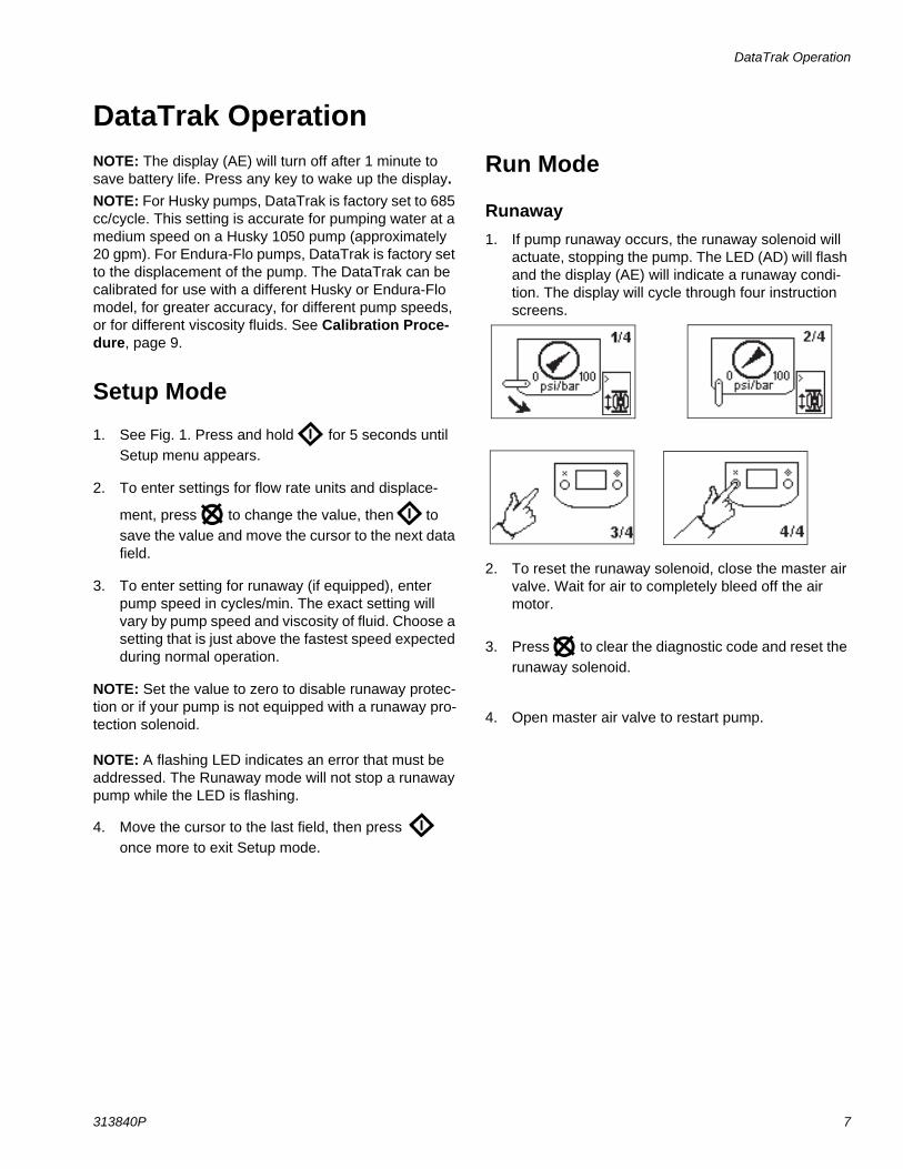
Runaway1. If pump runaway occurs, the runaway solenoid will
actuate, stopping the pump. The LED (AD) will flash and the display (AE) will indicate a runaway condi-tion. The display will cycle through four instruction screens.
2. To reset the runaway solenoid, close the master air valve. Wait for air to completely bleed off the air motor.
3. Press to clear the diagnostic code and reset the runaway solenoid.
4. Open master air valve to restart pump.
DataTrak Operation
8 313840P
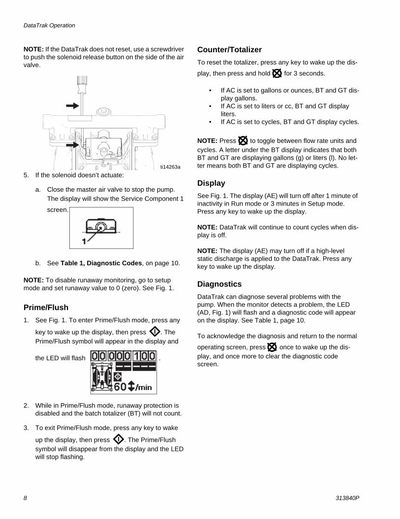
NOTE: If the DataTrak does not reset, use a screwdriver to push the solenoid release button on the side of the air valve.
5. If the solenoid doesn’t actuate:
a. Close the master air valve to stop the pump. The display will show the Service Component 1
screen.
b. See Table 1, Diagnostic Codes, on page 10.
NOTE: To disable runaway monitoring, go to setup mode and set runaway value to 0 (zero). See Fig. 1.
Prime/Flush1. See Fig. 1. To enter Prime/Flush mode, press any
key to wake up the display, then press . The Prime/Flush symbol will appear in the display and
the LED will flash .
2. While in Prime/Flush mode, runaway protection is disabled and the batch totalizer (BT) will not count.
3. To exit Prime/Flush mode, press any key to wake
up the display, then press . The Prime/Flush symbol will disappear from the display and the LED will stop flashing.
Counter/TotalizerTo reset the totalizer, press any key to wake up the dis-
play, then press and hold for 3 seconds.
• If AC is set to gallons or ounces, BT and GT dis-play gallons.
• If AC is set to liters or cc, BT and GT display liters.
• If AC is set to cycles, BT and GT display cycles.
NOTE: Press to toggle between flow rate units and cycles. A letter under the BT display indicates that both BT and GT are displaying gallons (g) or liters (l). No let-ter means both BT and GT are displaying cycles.
DisplaySee Fig. 1. The display (AE) will turn off after 1 minute of inactivity in Run mode or 3 minutes in Setup mode. Press any key to wake up the display.
NOTE: DataTrak will continue to count cycles when dis-play is off.
NOTE: The display (AE) may turn off if a high-level static discharge is applied to the DataTrak. Press any key to wake up the display.
DiagnosticsDataTrak can diagnose several problems with the pump. When the monitor detects a problem, the LED (AD, Fig. 1) will flash and a diagnostic code will appear on the display. See Table 1, page 10.
To acknowledge the diagnosis and return to the normal
operating screen, press once to wake up the dis-play, and once more to clear the diagnostic code screen.
ti14263a
DataTrak Operation
313840P 9
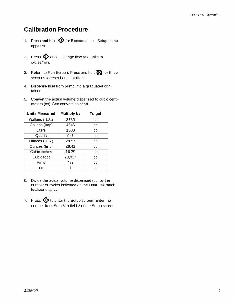
Calibration Procedure
1. Press and hold for 5 seconds until Setup menu appears.
2. Press once. Change flow rate units to cycles/min.
3. Return to Run Screen. Press and hold for three seconds to reset batch totalizer.
4. Dispense fluid from pump into a graduated con-tainer.
5. Convert the actual volume dispensed to cubic centi-meters (cc). See conversion chart.
6. Divide the actual volume dispensed (cc) by the number of cycles indicated on the DataTrak batch totalizer display.
7. Press to enter the Setup screen. Enter the number from Step 6 in field 2 of the Setup screen.
Units Measured Multiply by To getGallons (U.S.) 3785 ccGallons (Imp) 4546 cc
Liters 1000 ccQuarts 946 cc
Ounces (U.S.) 29.57 ccOunces (Imp) 28.41 ccCubic inches 16.39 cc
Cubic feet 28,317 ccPints 473 cc
cc 1 cc
DataTrak Operation
10 313840P
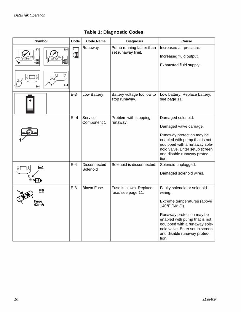
Table 1: Diagnostic Codes
Symbol Code Code Name Diagnosis Cause
Runaway Pump running faster than set runaway limit.
Increased air pressure.
Increased fluid output.
Exhausted fluid supply.
E-3 Low Battery Battery voltage too low to stop runaway.
Low battery. Replace battery; see page 11.
E--4 ServiceComponent 1
Problem with stopping runaway.
Damaged solenoid.
Damaged valve carriage.
Runaway protection may be enabled with pump that is not equipped with a runaway sole-noid valve. Enter setup screen and disable runaway protec-tion.
E-4 Disconnected Solenoid
Solenoid is disconnected. Solenoid unplugged.
Damaged solenoid wires.
E-6 Blown Fuse Fuse is blown. Replace fuse; see page 11.
Faulty solenoid or solenoid wiring.
Extreme temperatures (above 140°F [60°C]).
Runaway protection may be enabled with pump that is not equipped with a runaway sole-noid valve. Enter setup screen and disable runaway protec-tion.
DataTrak Operation
313840P 11
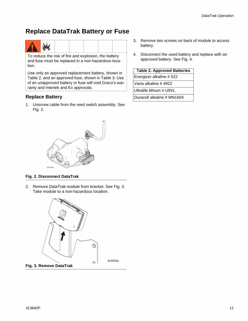
Replace DataTrak Battery or Fuse
Replace Battery1. Unscrew cable from the reed switch assembly. See
Fig. 2.
2. Remove DataTrak module from bracket. See Fig. 3. Take module to a non-hazardous location.
3. Remove two screws on back of module to access battery.
4. Disconnect the used battery and replace with an approved battery. See Fig. 4.
To reduce the risk of fire and explosion, the battery and fuse must be replaced in a non-hazardous loca-tion.
Use only an approved replacement battery, shown in Table 2, and an approved fuse, shown in Table 3. Use of an unapproved battery or fuse will void Graco’s war-ranty and Intertek and Ex approvals.
Fig. 2. Disconnect DataTrak
Fig. 3. Remove DataTrakti14053a
Table 2. Approved BatteriesEnergizer alkaline # 522
Varta alkaline # 4922
Ultralife lithium # U9VL
Duracell alkaline # MN1604
DataTrak Operation
12 313840P
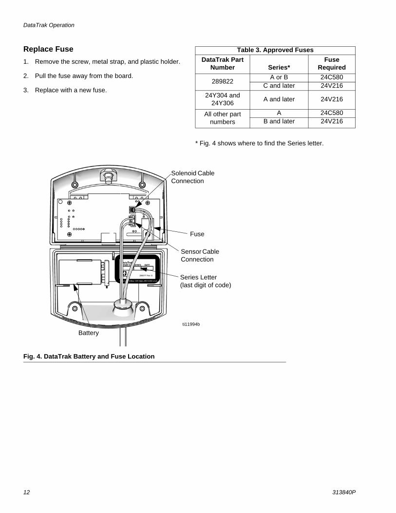
Replace Fuse1. Remove the screw, metal strap, and plastic holder.
2. Pull the fuse away from the board.
3. Replace with a new fuse.
* Fig. 4 shows where to find the Series letter.
Table 3. Approved FusesDataTrak Part
Number Series*Fuse
Required
289822A or B 24C580
C and later 24V21624Y304 and
24Y306 A and later 24V216
All other part numbers
A 24C580B and later 24V216
Fig. 4. DataTrak Battery and Fuse Location
ti11994b
Battery
Fuse
Solenoid Cable Connection
Sensor Cable Connection
Series Letter(last digit of code)

DataTrak Operation
313840P 13
Parts
14 313840P
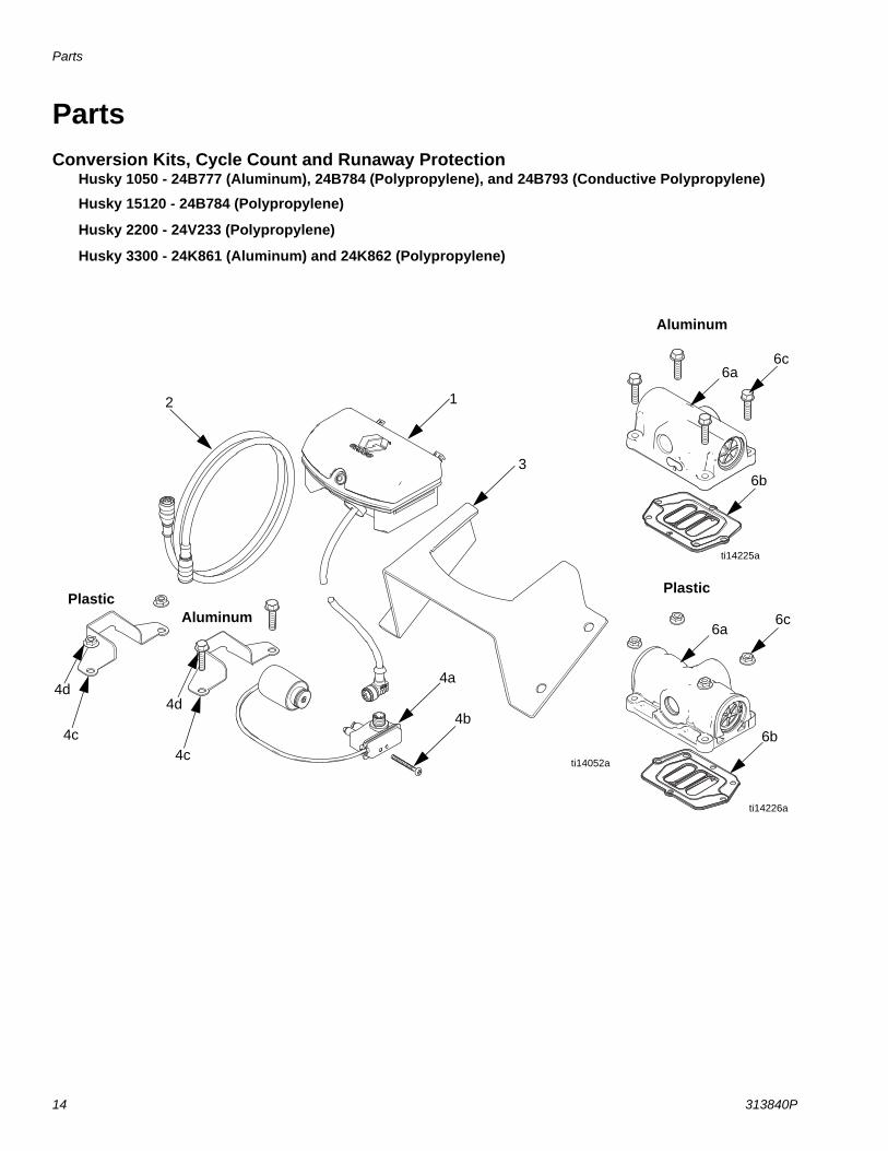
PartsConversion Kits, Cycle Count and Runaway Protection
Husky 1050 - 24B777 (Aluminum), 24B784 (Polypropylene), and 24B793 (Conductive Polypropylene)
Husky 15120 - 24B784 (Polypropylene)
Husky 2200 - 24V233 (Polypropylene)
Husky 3300 - 24K861 (Aluminum) and 24K862 (Polypropylene)
ti14052a
AluminumPlastic
12
3
4a
4b
Aluminum
Plastic
6a
6b
6c
6a
6b
6c
4d
4c
ti14226a
ti14225a
4d
4c
Parts
313840P 15
Replacement Warning labels, signs, tags, and cards are available at no cost.
----- Not sold separately.
Ref. No. Part No. Description Qty1 ----- DATATRAK module
(see pages 11 and 12 for battery and fuse replacement information)
1
2 ----- CABLE 13 ----- BRACKET, wall 14 SOLENOID/REED SWITCH, kit
(includes Parts 4a-4d)1
24B771 Husky 1050 and 15120 plastic air valve
24B772 Husky 1050 aluminum air valve24K863 Husky 2200 and 3300 plastic air
valve24K864 Husky 3300 aluminum air valve
4a ----- REED SWITCH with SOLENOID 14b ----- SCREW, reed switch
8-32 x 1.50 taptite, aluminum air valve6-19 x 1-5/8 plastite, plastic air valve
1
4c ----- BRACKET, solenoid 14d ----- FASTENER, solenoid
M6 x 25 screw, aluminum air valveM6 hex nut, plastic air valve
2
6 AIR VALVE, kit(includes Parts 6a-6c)
1
24B767 Husky 1050 Aluminum24B774 Husky 1050 and 15120
Polypropylene24B776 Husky 1050 Conductive
Polypropylene24V232 Husky 2200 Polypropylene24K856 Husky 3300 Aluminum24K858 Husky 3300 Polypropylene
6a ----- VALVE, air, smart 16b ----- GASKET, air valve 16c ----- FASTENERS, air valve
M6 x 25 screw, Aluminum air valveM6 hex nut, Plastic air valve
4
7 15V262 LABEL, warning (not shown) 18 16A098 CARD, reference, language (not
shown)1
Ref. No. Part No. Description Qty
Parts
16 313840P
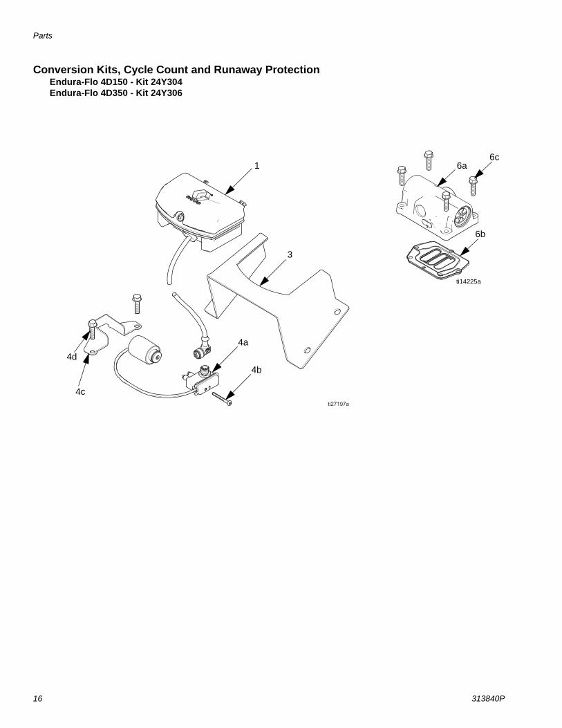
Conversion Kits, Cycle Count and Runaway ProtectionEndura-Flo 4D150 - Kit 24Y304Endura-Flo 4D350 - Kit 24Y306
6a
6b
6c
ti14225a
1
3
4b4d
4c
4a
Parts
313840P 17
Replacement Warning labels, signs, tags, and cards are available at no cost.
----- Not sold separately.
Ref. No. Part No. Description Qty1 ----- DATATRAK module
(see pages 11 and 12 for battery and fuse replacement information)
1
3 ----- BRACKET, wall 14 SOLENOID/REED SWITCH, kit
(includes Parts 4a-4d)1
17H320 for 4D15017H321 for 4D350
4a ----- REED SWITCH with SOLENOID 14b ----- SCREW, reed switch
8-32 x 1.50 taptite1
4c ----- BRACKET, solenoid 14d ----- FASTENER, solenoid
M6 x 20 screw4
6 AIR VALVE, kit(includes Parts 6a-6c)
1
17H318 for 4D15017H316 for 4D350
6a ----- VALVE, air, smart 16b ----- GASKET, air valve 16c ----- FASTENERS, air valve
M6 x 20 screw4
7 15V262 LABEL, warning (not shown) 18 16A098 CARD, reference, language (not
shown)1
Ref. No. Part No. Description Qty
Parts
18 313840P
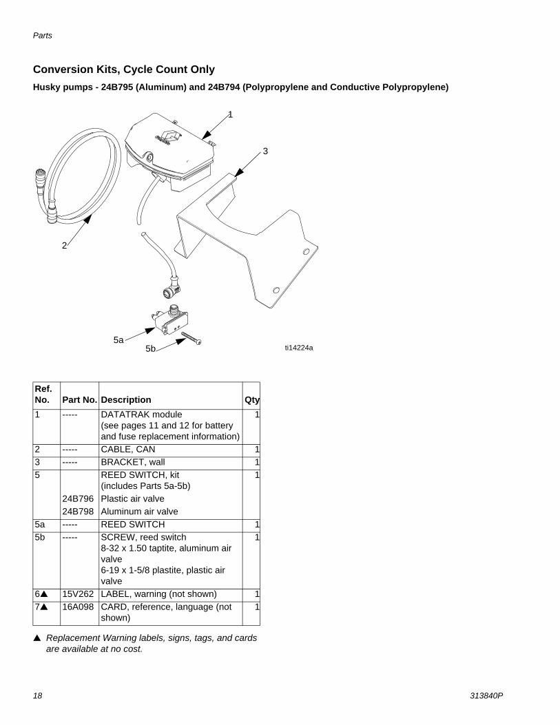
Conversion Kits, Cycle Count OnlyHusky pumps - 24B795 (Aluminum) and 24B794 (Polypropylene and Conductive Polypropylene)
Replacement Warning labels, signs, tags, and cards are available at no cost.
1
2
3
5a5b ti14224a
Ref. No. Part No. Description Qty1 ----- DATATRAK module
(see pages 11 and 12 for battery and fuse replacement information)
1
2 ----- CABLE, CAN 13 ----- BRACKET, wall 15 REED SWITCH, kit
(includes Parts 5a-5b)1
24B796 Plastic air valve24B798 Aluminum air valve
5a ----- REED SWITCH 15b ----- SCREW, reed switch
8-32 x 1.50 taptite, aluminum air valve6-19 x 1-5/8 plastite, plastic air valve
1
6 15V262 LABEL, warning (not shown) 17 16A098 CARD, reference, language (not
shown)1
Parts
313840P 19
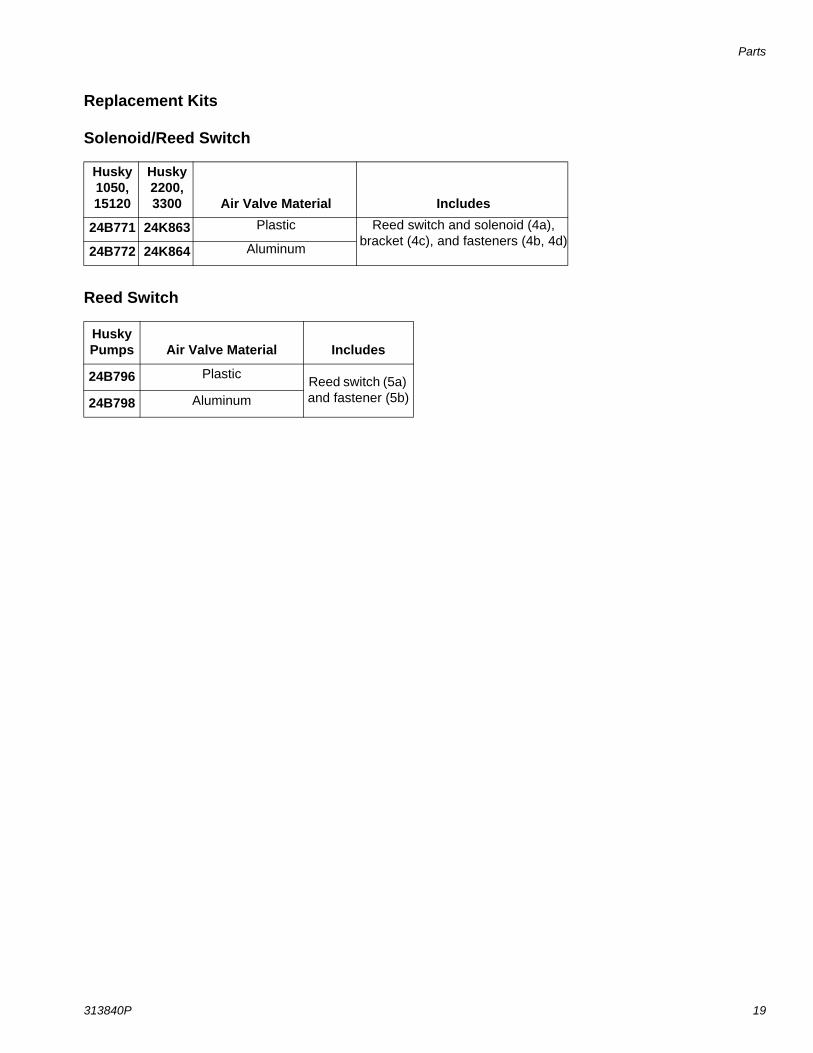
Replacement Kits
Solenoid/Reed Switch
Reed Switch
Husky 1050, 15120
Husky 2200,3300 Air Valve Material Includes
24B771 24K863 Plastic Reed switch and solenoid (4a), bracket (4c), and fasteners (4b, 4d)
24B772 24K864 Aluminum
Husky Pumps Air Valve Material Includes
24B796 Plastic Reed switch (5a) and fastener (5b)24B798 Aluminum

All written and visual data contained in this document reflects the latest product information available at the time of publication. Graco reserves the right to make changes at any time without notice.
Original instructions.This manual contains English. MM 313840Graco Headquarters: Minneapolis
International Offices: Belgium, China, Japan, Korea
GRACO INC. AND SUBSIDIARIES • P.O. BOX 1441 • MINNEAPOLIS MN 55440-1441 • USA
Copyright 2009, Graco Inc. All Graco manufacturing locations are registered to ISO 9001.www.graco.com
Revision P, April 2019
Graco Standard WarrantyGraco warrants all equipment referenced in this document which is manufactured by Graco and bearing its name to be free from defects in material and workmanship on the date of sale to the original purchaser for use. With the exception of any special, extended, or limited warranty published by Graco, Graco will, for a period of twelve months from the date of sale, repair or replace any part of the equipment determined by Graco to be defective. This warranty applies only when the equipment is installed, operated and maintained in accordance with Graco’s written recommendations.
This warranty does not cover, and Graco shall not be liable for general wear and tear, or any malfunction, damage or wear caused by faulty installation, misapplication, abrasion, corrosion, inadequate or improper maintenance, negligence, accident, tampering, or substitution of non-Graco component parts. Nor shall Graco be liable for malfunction, damage or wear caused by the incompatibility of Graco equipment with structures, accessories, equipment or materials not supplied by Graco, or the improper design, manufacture, installation, operation or maintenance of structures, accessories, equipment or materials not supplied by Graco.
This warranty is conditioned upon the prepaid return of the equipment claimed to be defective to an authorized Graco distributor for verification of the claimed defect. If the claimed defect is verified, Graco will repair or replace free of charge any defective parts. The equipment will be returned to the original purchaser transportation prepaid. If inspection of the equipment does not disclose any defect in material or workmanship, repairs will be made at a reasonable charge, which charges may include the costs of parts, labor, and transportation.
THIS WARRANTY IS EXCLUSIVE, AND IS IN LIEU OF ANY OTHER WARRANTIES, EXPRESS OR IMPLIED, INCLUDING BUT NOT LIMITED TO WARRANTY OF MERCHANTABILITY OR WARRANTY OF FITNESS FOR A PARTICULAR PURPOSE.
Graco’s sole obligation and buyer’s sole remedy for any breach of warranty shall be as set forth above. The buyer agrees that no other remedy (including, but not limited to, incidental or consequential damages for lost profits, lost sales, injury to person or property, or any other incidental or consequential loss) shall be available. Any action for breach of warranty must be brought within two (2) years of the date of sale.
GRACO MAKES NO WARRANTY, AND DISCLAIMS ALL IMPLIED WARRANTIES OF MERCHANTABILITY AND FITNESS FOR A PARTICULAR PURPOSE, IN CONNECTION WITH ACCESSORIES, EQUIPMENT, MATERIALS OR COMPONENTS SOLD BUT NOT MANUFACTURED BY GRACO. These items sold, but not manufactured by Graco (such as electric motors, switches, hose, etc.), are subject to the warranty, if any, of their manufacturer. Graco will provide purchaser with reasonable assistance in making any claim for breach of these warranties.
In no event will Graco be liable for indirect, incidental, special or consequential damages resulting from Graco supplying equipment hereunder, or the furnishing, performance, or use of any products or other goods sold hereto, whether due to a breach of contract, breach of warranty, the negligence of Graco, or otherwise.
FOR GRACO CANADA CUSTOMERSThe Parties acknowledge that they have required that the present document, as well as all documents, notices and legal proceedings entered into, given or instituted pursuant hereto or relating directly or indirectly hereto, be drawn up in English. Les parties reconnaissent avoir convenu que la rédaction du présente document sera en Anglais, ainsi que tous documents, avis et procédures judiciaires exécutés, donnés ou intentés, à la suite de ou en rapport, directement ou indirectement, avec les procédures concernées.
Graco InformationFor the latest information about Graco products, visit www.graco.com.
For patent information, see www.graco.com/patents.
TO PLACE AN ORDER, contact your Graco distributor or call to identify the nearest distributor.Phone: 612-623-6921 or Toll Free: 1-800-328-0211 Fax: 612-378-3505