controltech - snap-on
TRANSCRIPT

ControlTech ™
ELECTRONIC
TORQUE-ANGLE
WRENCH

1
IMPORTANT SAFETY INSTRUCTIONS
WARNING Risk of flying particles.
Over-torquing can cause breakage. Force against flex stops on flex head can cause head breakage. An out of calibration angle wrench can cause part or tool breakage. Broken hand tools, sockets or accessories can cause injury. Excess force can cause crowfoot or flare nut wrench slippage.
Read this manual completely before using ELECTRONIC WRENCH.
To insure accuracy, work must not move in angle mode.
For personal safety and to avoid wrench damage, follow good professional tool and fastener installation practices.
Periodic recalibration is necessary to maintain accuracy.
Wear safety goggles, user and bystanders.
Be sure all components, including all adaptors, extensions, drivers and sockets are rated to match or exceed torque being applied.
Observe all equipment, system and manufacturer's warnings, cautions and procedures when using this wrench.
Use correct size socket for fastener.
Do not use sockets showing wear or cracks.
Replace fasteners with rounded corners.
To avoid damaging wrench: Never use wrench with power off. Always turn ON wrench so applied torque is being measured.
Do not press POWER while torque is applied or while wrench is in motion.
Never use this wrench to break fasteners loose.
Do not use extensions, such as a pipe, on handle of wrench.
Check that wrench capacity matches or exceeds each application before proceeding.
When using negative offsets, verify maximum targets are not exceeded (see tables on page 6).
Verify calibration if dropped.
Make sure ratchet direction lever is fully engaged in correct position.
Verify calibration of wrench if you know or suspect its capacity has been exceeded.
Do not force head of flex head drives against stops.
Always adjust your stance to prevent a possible fall should something give while using wrench.
Do not attempt to recharge alkaline cells.
Store wrench in dry place.
Remove batteries when storing wrench used for periods longer than 3 months.
WARNING Electrical Shock Hazard. Electrical shock can cause injury. Metal handle is not isolated. Do not use on live electrical circuits.
SAVE THESE INSTRUCTIONS
Disclaimer Operation of ControlTechTM Wrench is not warranted in an EU member state if operating instructions are not in that State’s language. Contact Snap-on if a translation is needed.

2
Specifications
Head Type
Square drive 72 or 80 teeth, sealed flex and fixed ratchet
Fixed square drive
J, Y, X and Z-Shank Female Type
Display
DISPLAY TYPE: Dot Matrix LCD (192 x 65 Resolution)
VIEWING DIRECTION: 6:00
BACKLIGHT: WHITE (LED)
Sealed Button Pad
POWER - ON/OFF and torque and angle re-zero
ENTER - Measurement mode select and menu entry
UP – Increments torque and angle settings and menu navigation
DOWN - Decrements torque and angle settings and menu navigation
UNITS - Units select (ft-lbs, in-lbs, Nm, Kgm, Kg-cm, dNm) and enter PSET (preset) menu
LCD BACKLIGHT – Illuminates all screens and last peak torque or angle recall
Functions
Set - torque or angle target
Track - real time display of torque or accumulated angular rotation with progress lights
Peak Hold – 5 sec. flashing of peak torque or alternating peak torque/angle on release of torque
Peak Recall - display last peak torque or peak torque/angle on button press
Memory - display of last 1500 peak torque or peak torque/angle readings Accuracy
Temperature: @ 22 C (72°F)
Angle: ±1% of reading ±1° @ angular velocity > 10°/sec < 180°/sec CW CCW
Torque: ±2% ±3% of reading, 20% to 100% of full scale (unflexed) ±4% ±6% of reading, 5% to 19% of full scale
Dimensions: Length / Weight/Drive
Preset Range
ANGLE: 0 to 360° CW or CCW (Display Resolution 1°)
TORQUE: (Display Range and Resolution as shown below)
Operating Temperature: 0°F - 130°F (-18°C to 54°C) Storage Temperature: 0°F to 130°F (-18°C to 54°C) Measurement Drift: ANGLE: -0.12 Angular Degrees per Degree C
TORQUE: +0.01% of reading per Degree C Humidity: Up to 90% non-condensing Battery: Three "AA" Alkaline Cells, up to 80 hours continuous operation
(Three "AAA" for 240 models, up to 60 hours continuous operation) Default Auto Shut-off: After 2 minutes idle – (Adjustable, see Advanced Settings)
Flex Head Model Length Weight Square Drive Fixed Head Model Length Weight Square Drive Interchangeable Head Length Weight
CTECH1FR240A 14.1 in. 1.97 lbs. ¼ in. CTECH1R240A 14.1 in. 1.97 lbs. ¼ in. CTECH1J240A 12.5 in. 1.8 lbs.
CTAL1240A 12.4 in. 1.1 lbs. ¼ in. CTAL1J240A 12.5 in. 1.0 lbs.
CTAL1R240A 14.1 in. 1.2 lbs. ¼ in.
CTECH2FR100A 18.9 in. 3.1 lbs. ⅜ in. CTECH2R100A 18.9 in. 3.1 lbs. ⅜ in. CTECH2Y100A 17.2 in. 2.7 lbs
CTECH3FR250A 26.7 in. 4.5 lbs. ½ in. CTECH3R250LA 32.9 in. 5.5 lbs. ½ in. CTECH3X250A 24.1 in. 3.6 lbs.
CTECH4RN650A 35.8 in. 8.7 lbs. ¾ in. CTECH4ZN650A 32.1 in. 5.7 lbs.
CTECH4R600A 48.6 in. 10.5 lbs. ¾ in. CTECH4Z600A 44.8 in. 7.6 lbs.
Flex Head Model Fixed Head Model Interchangeable Head ft-lb in-lbs Nm Kgm kg-cm dNm overload (ft-lb)
CTECH1FR240A CTECH1R240A CTECH1J240A 1.00-20.00 12.0-240.0 1.36-27.12 N/A 13.8-276.5 13.6-27.12 25
CTAL1240A CTAL1J240A 1.00-20.00 12.0-240.0 1.36-27.12 N/A 13.8-276.5 13.6-27.12 25
CTAL1R240A 1.00-20.00 12.0-240.0 1.36-27.12 N/A 13.8-276.5 13.6-27.12 25
CTECH2FR100A CTECH2R100A CTECH2Y100A 5.0-100.0 60-1200 6.8-135.6 N/A 69-1383 68-1356 125
CTECH3FR250A CTECH3R250LA CTECH3X250A 12.5-250.0 150-3000 16.9-339.0 1.73-34.56 N/A N/A 312
CTECH4RN650A CTECH4ZN650A 24.0-479.4 288-5753 32.5-650.0 3.31-66.28 N/A N/A 600
CTECH4R600A CTECH4Z600A 30.0-600.0 360-7200 40.7-813.5 4.15-82.95 N/A N/A 750

3
User Instructions
Basic Functions (Quick Start)
Figure 1
Install three fresh Alkaline “AA” cells into handle of wrench. (“AAA” for 240 models)
Wrench Power On Sequence
Note: Do not turn on wrench while torque is applied, otherwise torque zero offset will be incorrect and wrench will indicate a torque reading when torque is released. If this occurs, re-zero wrench by momentarily pressing POWER button while wrench is on a stable surface with no torque applied.
1. Turn On Wrench. While holding wrench still, monetarily press POWER button. Snap-on logo will be displayed followed by torque and angle re-zeroing screens (if angle mode has been previously selected). If real-time-clock has not been set, date and time entry screens are displayed (see Advanced Configuration section for entering date and time). After entering date and time or if time has been previously set, target TORQUE or ANGLE screen will now be displayed depending on previous measurement mode selected.
2. Select Measurement Mode. Toggle between target TORQUE and ANGLE screens by repeatedly pressing ENTER button.
Note: When date and time is set for first time, In-Service date is also set and is used for calculating
initial calibration interval (see "Setting Calibration Interval" in Advanced Configuration section).
MODE COUNT
AUDIBLE ALERT
MODE SELECT AND MENU ENTRY BUTTON
INCREMENT BUTTON
ON/OFF AND RE-ZERO BUTTON
DECREMENT BUTTON
LCD BACKLIGHT AND
PEAK TORQUE/ANGLE RECALL BUTTON
UNITS AND PRESET ENTRY
BUTTON
TORQUE AND/OR ANGLE DISPLAY
BATTERY CONDITION
USB CONNECTOR
PROGRESS LIGHTS
PROGRESS LIGHTS
DATA STORAGE
ALERT
PROGRESS LIGHTS Yellow - First light indicates 40% of
target torque or angle reached, Second indicates 60% of target reached, Third indicates 80% of target reached.
Green - Indicates target torque or angle reached.
Red - Indicates exceeded torque or angle target plus 4% or exceeded maximum Preset target.
TORQUE ZEROING ANGLE ZEROING
-- SET STILL
UP/DOWN buttons
00
250.0 FT-LB
00
180°
SET DATE 2014/01/01 YR MON DAY
ENTER button
SET TIME 12 : 00 : 00 HR MIN SEC
UP/DOWN buttons
ENTER button
Target Angle Screen Target Torque Screen

4
Note: If wrench is powered up in torque only measurement mode, angle is not zeroed until mode is changed to angle measurement mode, at which time torque and angle zeroing begins automatically after 2 seconds. Wrench should be placed on a stable surface with no torque applied.
Note: Pressing ENTER button while angle is zeroing will abort zeroing function to allow user to select another measurement mode.
Torque Mode
1. Set Target. Use UP/DOWN buttons to change TORQUE target value.
2. Select Units of Measure. Repeatedly press UNITS button while on target TORQUE screen until desired units are displayed.
3. Apply TORQUE. Grasp center of handle and slowly apply torque to fastener until progress lights display green and a ½ second audible alert and handle vibration alerts you to stop.
4. Release TORQUE. Note peak TORQUE reading flashing on LCD display for 5 seconds. Pressing BACKLIGHT button while peak torque is flashing will continue to display value until button is released. Momentarily pressing UP/DOWN, ENTER or UNITS button will immediately return to target TORQUE screen. Reapplying TORQUE will immediately start another TORQUE measurement cycle.
5. Recall Peak TORQUE Reading To recall last peak TORQUE measurement, press and hold BACKLIGHT button for approximately 3 seconds. Peak TORQUE will flash for 5 seconds.
Angle Mode
Note: When angle measurement mode is selected for first time following a power on, "ANGLE ZERO REQUIRED" message is displayed. After two seconds angle zero process begins and wrench must be placed on a stable surface. If ENTER button is pressed before two seconds to change to torque only mode, angle zero process is skipped.
1. Set target. Use UP/DOWN buttons to change target ANGLE value.
2. Apply Torque and Rotate Wrench. Grasp center of handle and slowly apply torque to fastener and rotate wrench at a moderate consistent speed until progress lights display green and a ½ second audible alert and handle vibration alerts you to stop.
3. Release torque. Note alternating peak TORQUE and ANGLE readings flashing on LCD display for 5 seconds. Pressing BACKLIGHT button while peak values are flashing will continue to display values until button is released. Momentarily pressing UP/DOWN, ENTER or UNITS button will immediately return to target ANGLE screen. Reapplying torque (ratcheting) before target screen is displayed will continue ANGLE accumulation as wrench is rotated.
4. Recall Peak ANGLE Reading To recall last peak ANGLE measurement, press and hold BACKLIGHT button for approximately 3 seconds. Peak TORQUE and ANGLE will be displayed alternately for 5 seconds.
Mode Cycle Count
ControlTech™ mode cycle count feature is used to indicate number of times wrench has reached target torque in torque measurement mode or target angle in angle measurement mode.
01
M 180°
MEMORY ICON MODE CYCLE COUNT

5
Torque and Angle Mode Cycle Counting
1. Numerical counter located in top right of target torque or target angle screen will increment after each torque or angle cycle if applied torque or angle has reached target value.
2. When toggling between torque mode or angle mode using ENTER button or if target is changed, numerical counter will reset back to 00. Counter WILL NOT reset when re-zeroing, on menu entry/exit or power down.
3. Memory icon will turn on indicating at least one torque or angle cycle data has been stored in memory.
Data Download
Torque and Angle data in memory can be downloaded to a computer via USB port.
Note: When downloading data from a wrench that has previous downloaded data, rename previous file or move it to a different directory to prevent overwrite. However, Windows® will notify user of duplicate file names and allow user to skip download, overwrite existing file or save new file as a second copy.
1. Connect supplied USB cable from computer to wrench.
2. Computer will display "AutoPlay" window showing CTECH as a disk drive with option of using Windows Explorer to view files:
3. Click "Open Folder" selection to display CTECH Character Separated Value (.csv) file.
Note: If "AutoPlay" does not start automatically, use Explorer to display CTECH drive contents.
4. Open file using Microsoft Excel by double clicking on file name (Example: "1213590002.CSV") or "drag and drop" file to computer.
5. Data on wrench can be cleared by deleting file on CTECH drive.
Main Menu
Main menu displays wrench operational information.
1. From target torque or angle screen, press and hold ENTER button for 3 seconds.
2. Use UP/DOWN buttons to highlight menu selection then press ENTER button.
Menu Selections:
EXIT - Exits Main menu and returns to target screen.
LANGUAGE - Displays language selection menu.
SET HEAD LENGTH - Displays wrench head length entry screen.
SHOW DATA - Displays stored torque and angle data.

6
CLEAR DATA - Clears stored torque and angle data.
CYCLE COUNT - Displays torque/angle cycle count screen.
SETTINGS - Displays advanced settings menu (see Advanced Settings Section).
CONFIGURE - Displays advanced configuration menu (see Advanced Configuration Section).
3. To select language menu, press ENTER button while LANGUAGE is highlighted then highlight desired language and press ENTER button.
4. Decimal Mark selection menu is displayed. Decimal separator can be a comma or decimal point. Use UP/DOWN buttons to select decimal separator then press the ENTER button.
Note: Decimal separator will affect formatting of downloaded data when opened by Excel depending on Windows® regional settings.
5. To exit Main menu and return to target torque or angle screen, press ENTER button while EXIT
menu selection is highlighted.
Setting Head Length
Note: If wrench has an interchangeable head or an adapter or extension is added, length of head, adapter and/or extension being used can be entered to correct for a different length than head used to calibrate wrench, without requiring re-calibration.
1. To enter a head length, from target torque or angle screen, press and hold ENTER button for 3 seconds.
2. With SET HEAD LENGTH menu selection highlighted, momentarily press ENTER button.
3. Set Head Length screen is displayed next. Default head length is length of head at calibration (zero for fixed head wrench) and is displayed with most-significant digit highlighted. Use UP/DOWN buttons to increment/decrement head length. Pressing and holding UP/DOWN buttons will progressively increment/decrement value faster.
4. Press ENTER button to accept digit and highlight next-significant digit.
5. Default units of length is in inches. Press UNITS button to change to millimeters.
6. Pressing ENTER button after least-significant digit is set returns to main menu. If length is changed from default, "OFFSET IN USE" message will be displayed on target screen.
Note: If UP/DOWN buttons are pressed simultaneously while on Set Head Length screen, displayed head length resets to zero or calibration head length for interchangeable head wrenches.
Decimal Mark Selection menu
DECIMAL MARK
COMMA (1,23)
POINT (1.23)
ENTER button
UP/DOWN buttons
DECIMAL MARK
COMMA (1,23)
POINT (1.23)
00
100,0 FT-LB
ENTER button
00
100.0 FT-LB
EXIT
LANGUAGE
SET HEAD LENGTH
SHOW DATA
ENTER button
held
Target Screen Main menu
ENGLISH
FRANCAIS
ESPANOL
DEUTSCH
ENTER button
Language Selection menu
00
100.0 FT-LB
EXIT LANGUAGE SET HEAD LENGTH SHOW DATA
UP/DOWN buttons
00 OFFSET IN USE
100.0 FT-LB
ENTER button (while least-significant digit highlighted)
EXIT LANGUAGE SET HEAD LENGTH SHOW DATA
SET HEAD LENGTH
3.000 IN
M
ENTER button
held
Target Screen
ENTER button
UP/DOWN/ENTER buttons
UNITS button
SET HEAD LENGTH
076.2
MM UP/DOWN/ENTER
buttons

7
Note: For a fixed length head, head length entered is offset length measured from center of drive to center of fastener.
Note: For an interchangeable head, head length is measured from locking pin to center of drive. SET HEAD LENGTH is set during calibration. If a different length head is used, enter new head length and offset is calculated automatically.
Note: For an interchangeable head with an adapter, head length entered is sum of head length and offset length.
Use of Negative Offsets
Note: Enter a negative value for offset when used in reverse direction with flex head or when calculating sum of interchangeable head and offset lengths.
When length of an offset (or sum of head minus offset for interchangeable head) is negative, maximum fastener target is limited by following formulas:
240 in-lb wrench:
Maximum Target Torque = offset * 24 + 240
100 ft-lb wrench:
Maximum Target Torque = offset * 7 + 100
Offset Max Target Offset Max Target -1" 216 in-lb -1" 93 ft-lb
-2" 192 in-lb -2" 86 ft-lb
-3" 168 in-lb -3" 79 ft-lb -4" 144 in-lb -4" 72 ft-lb
250 ft-lb wrench:
Maximum Target Torque = offset * 11 + 250 250L ft-lb wrench:
Maximum Target Torque = offset * 8 + 250
Offset Max Target Offset Max Target
-1" 239 ft-lb -1" 242 ft-lb -2" 228 ft-lb -2" 234 ft-lb
-3" 217 ft-lb -3" 226 ft-lb -4" 206 ft-lb -4" 218 ft-lb
600 ft-lb wrench:
Maximum Target Torque = offset * 14 + 600
Offset Max Target
-1" 586 ft-lb
-2" 572 ft-lb -3" 558 ft-lb
-4" 544 ft-lb
𝑜𝑓𝑓𝑠𝑒𝑡
ℎ𝑒𝑎𝑑
𝑜𝑓𝑓𝑠𝑒𝑡
ℎ𝑒𝑎𝑑
𝑜𝑓𝑓𝑠𝑒𝑡
ℎ𝑒𝑎𝑑

8
Note: When using a negative offset, entering a target torque greater than maximum values above may cause an overtorque error before reaching fastener target torque and possibly damage wrench.
Viewing Stored Torque and Angle Data
Torque data is stored in memory after each torque cycle if applied torque has reached target value. Torque and angle data is stored in memory after each angle cycle if applied angle has reached target value. Memory Indicator is displayed when data is stored in non-volatile memory.
1. To view stored torque and angle data, from target torque or angle screen, press and hold ENTER button for 3 seconds.
2. Highlight SHOW DATA menu selection by pressing UP/DOWN buttons then press ENTER button to display Show Data screen.
3. In Show Data screen, scroll through each stored data record by pressing UP/DOWN buttons.
Example: 0002 = Show Data List Counter: TQ = Peak torque value 0001 = Show Data List Counter: TQ = Peak torque value: ANG = Peak angle value
4. Pressing ENTER button while on Show Data screen returns to main menu.
Note: A maximum of 1500 data records can be stored in memory. Memory full icon will be displayed
when full and no more data is stored until memory is cleared. Deleting Stored Torque and Angle Data
1. From target torque or angle screen, press and hold ENTER button for 3 seconds.
2. Highlight CLEAR DATA menu selection using UP/DOWN buttons then press ENTER button to display CLEAR ALL DATA screen.
3. In CLEAR ALL DATA screen, highlight YES menu selection to delete all stored data, or NO menu selection to exit without deleting data.
4. Press ENTER button after making selection.
Note: If wrench is Locked (see Preset Lock in Advanced section), Clear Data function is disabled.
00
M 100.0 FT-LB
0002: 15:40:15 2012/09/26 TQ: 100.2 FT-LBS M
EXIT LANGUAGE SET HEAD LENGTH M SHOW DATA
UP/DOWN buttons
0001: 15:35:05 2012/09/26 TQ: 100.3 FT-LBS M ANG: 84°
EXIT LANGUAGE SET HEAD LENGTH M SHOW DATA
ENTER button
held
Target Screen
ENTER button
UP/DOWN buttons
00
M 100.0 FT-LB
EXIT SET HEAD LENGTH SHOW DATA CLEAR DATA
EXIT SET HEAD LENGTH SHOW DATA M CLEAR DATA
LANGUAGE SET HEAD LENGTH SHOW DATA M CLEAR DATA
CLEAR ALL DATA YES M NO
CLEAR ALL DATA YES M NO
EXIT LANGUAGE SET HEAD LENGTH M SHOW DATA
ENTER button
held
Target Screen
ENTER button
UP/DOWN buttons UP/DOWN buttons
ENTER button
ENTER button

9
Viewing and Clearing Wrench Cycle Counter
Each time torque or angle target is reached, wrench cycle counter is incremented. Maximum cycle count is 999999.
1. From target torque or angle screen, press and hold ENTER button for 3 seconds.
2. Highlight CYCLE COUNT menu selection using UP/DOWN buttons.
3. Press ENTER button to display CYCLE COUNT screen.
4. To exit CYCLE COUNT screen without clearing count, press ENTER button while EXIT menu selection is highlighted.
5. To reset wrench cycle count to 0, highlight CLEAR menu selection then press ENTER button.
6. EXIT menu selection is automatically highlighted after count is cleared. Press ENTER button to return to main menu.
Note: If wrench is Locked (see Preset Lock in Advanced section) Clear count function is disabled. Target Presets (PSET)
PSET function gives user ability to configure 50 preset target torque or target angle settings, each with a target, minimum, maximum (over range) and batch count value. PSETs are stored in non-volatile memory so that they are retained while power is off.
Note: After adding a Preset (see below), navigate between manual target torque, angle mode and PSET screen by repeatedly pressing ENTER button. While PSET screen is displayed, press UP/DOWN buttons to select additional configured PSETs.
SET HEAD LENGTH SHOW DATA CLEAR DATA M CYCLE COUNT
00
M 100.0 FT-LB
COUNT: 12 CLEAR M EXIT
COUNT: 12 CLEAR M EXIT
SET HEAD LENGTH SHOW DATA CLEAR DATA M CYCLE COUNT
EXIT LANGUAGE SET HEAD LENGTH M SHOW DATA
ENTER button
held
Target Screen
ENTER button
UP/DOWN buttons UP/DOWN buttons
ENTER button
ENTER button
COUNT: 0 CLEAR M EXIT
ENTER button
ENTER button
UP/Down buttons
PSET 03 00
50.0 FT-LB
Manual Target Angle Screen
PSET 02 04
90°
Preset 2 Angle Screen
Preset 3 Torque Screen
UP/Down buttons
UP/Down buttons
UP/Down buttons
ENTER button
ENTER button
ENTER button
00
90°
00
100.0 FT-LB
ENTER button
Manual Target Torque Screen
PSET 01 03
100.0 FT-LB
Preset 1 Torque Screen

10
Adding a Torque Preset
1. From manual target torque screen, select units of measure.
2. Press and hold UNITS button for 3 seconds.
3. ADD PRESET confirmation screen is displayed. Highlight YES menu selection using UP/DOWN buttons then press ENTER button. NO menu selection returns to main menu without adding a PSET.
4. TARGET TORQUE screen is displayed. TARGET TORQUE is target value of fastener. Initial TARGET TORQUE value is value from target torque screen. TARGET TORQUE can be set to any value within wrench torque range by pressing UP/DOWN buttons. Once desired target torque value has been set, press ENTER button.
5. MINIMUM TORQUE screen is displayed. MINIMUM TORQUE is value at which green progress lights, audible alert and vibrator turn on. Initial MINIMUM TORQUE value is TARGET TORQUE value minus negative torque tolerance (default 0%, see MODE SETUP in Advanced Configuration section). MINIMUM TORQUE can be set to any value from TARGET TORQUE to wrench minimum torque range by pressing UP/DOWN buttons. Once desired minimum torque value has been set, press ENTER button.
6. MAXIMUM TORQUE screen is displayed next. MAXIMUM TORQUE is torque value above which red progress lights turn on. Initial MAXIMUM TORQUE value will be TARGET TORQUE value plus positive torque tolerance (default 4%, see MODE SETUP in Advanced Configuration section). Maximum torque value can be set greater than TARGET TORQUE value to 10% above wrench maximum range by pressing UP/DOWN buttons. Once desired maximum torque value has been set, press ENTER button.
7. BATCH COUNT screen is displayed next. Default value is zero. Batch count range is 0 to 99. Press UP/DOWN buttons to increment/decrement batch count. Mode Count increments each time target torque is reached if a batch count of zero is entered. Mode Count decrements if a non-zero batch count is entered and resets to batch count value when count reaches zero. Once desired batch count value has been set, press ENTER button.
8. PSET target screen is displayed labeled with next available PSET number from 01 to 50.
9. To enter additional torque presets, repeatedly press ENTER button until target torque screen is displayed and repeat steps above.
MAXIMUM TORQUE
104.0 FT-LB
UP/DOWN buttons
ENTER button
BATCH COUNT
3
ENTER button
UP/DOWN buttons
ADD PRESET YES NO
ADD PRESET YES NO
00
100.0 FT-LB
UNIT button
held
Target Torque Screen
ENTER button
UP/DOWN buttons UP/DOWN buttons
ENTER button
ENTER button
TARGET TORQUE
100.0 FT-LB
MINIMUM TORQUE
100.0 FT-LB
PSET 01 03
100.0 FT-LB
Preset Torque Screen
UP/DOWN buttons
ENTER button

11
Adding an Angle Preset
1. From manual target angle screen, press and hold UNITS button for 3 seconds.
2. ADD PRESET confirmation screen is displayed. Highlight YES menu selection using UP/DOWN buttons then press ENTER button. NO menu selection returns to main menu without adding a PSET.
3. TARGET ANGLE screen is displayed. TARGET ANGLE is fastener rotational angle target value. Initial TARGET ANGLE value is value from target angle screen. TARGET ANGLE can be set from 0 to 360° by pressing UP/DOWN buttons. Once desired target angle value has been set, press ENTER button.
4. MINIMUM ANGLE screen is displayed. MINIMUM ANGLE is value at which green progress lights, audible alert and vibrator turn on. Initial MINIMUM ANGLE value is TARGET ANGLE minus negative angle tolerance (default 0%, see MODE SETUP in Advanced Configuration section). MINIMUM ANGLE can be set from 0 to TARGET ANGLE by pressing UP/DOWN buttons. Once desired minimum angle value has been set, press ENTER button.
5. MAXMUM ANGLE screen is displayed next. MAXIMUM ANGLE is angle value above which red progress lights turn on. Initial MAXIMUM ANGLE value will be TARGET ANGLE plus positive angle tolerance (default 4%, see MODE SETUP in Advanced Configuration section). MAXIMUM ANGLE value can be set to any value greater than TARGET ANGLE by pressing UP/DOWN buttons. Once desired value has been set, press ENTER button.
6. BATCH COUNT screen is displayed next. Default value is zero. Batch count range is 0 to 99. Press UP/DOWN buttons to increment/decrement batch count. Mode Count increments each time target angle is reached if a batch count of zero is entered. Mode Count decrements if a non-zero batch count is entered and resets to batch count value when count reaches zero. Once desired batch count value has been set, press ENTER button.
7. PSET target screen is displayed labeled with next available PSET number from 01 to 50.
8. To enter additional angle presets, repeatedly press ENTER button until target angle screen is displayed and repeat steps above.
Editing a Preset
Edit PSET function gives user ability to edit stored PSETS on wrench.
1. From Preset screen to be edited, press and hold UNITS button for 3 seconds.
2. CHANGE PRESET screen is displayed.
3. Highlight EDIT selection using UP/DOWN buttons then press ENTER button.
4. TARGET TORQUE or TARGET ANGLE screen is displayed. Value can be changed by pressing UP/DOWN buttons. Once desired target torque or angle value has been set, press ENTER button.
5. MINIMUM TORQUE or MINIMUM ANGLE screen is displayed. Value can be changed by pressing UP/DOWN buttons. Once desired torque or angle value has been set, press ENTER button.
6. MAXMUM TORQUE or MAXMUM ANGLE screen is displayed next. Value can be changed by pressing UP/DOWN buttons. Once desired torque or angle value has been set, press ENTER button.
MAXIMUM ANGLE
94°
ENTER button
UP/DOWN buttons
BATCH COUNT
4
UP/DOWN buttons
ADD PRESET YES NO
ADD PRESET YES NO
00
90°
UNIT button
held
Target Angle Screen
ENTER button
UP/DOWN buttons UP/DOWN buttons
ENTER button
ENTER button
TARGET ANGLE
90°
MINIMUM ANGLE
90°
PSET 02 04
90°
Preset Angle Screen
UP/DOWN buttons
ENTER button
ENTER button

12
7. BATCH COUNT screen is displayed next. Value can be changed by pressing UP/DOWN buttons. Once desired batch count value has been set, press ENTER button.
8. PSET target screen is displayed labeled with same PSET number.
Note: Pressing ENTER button while EXIT menu selection is highlighted will exit without editing PSET. Deleting a Preset
Delete PSET function allows user to remove stored presets from wrench.
1. From Preset screen to be deleted, press and hold UNITS button for 3 seconds.
2. CHANGE PRESET screen is displayed.
3. Highlight DELETE menu selection using UP/DOWN buttons and press ENTER button.
4. Target screen is displayed and deleted PSET is no longer available for selection.
Note: Pressing ENTER button while EXIT menu selection is highlighted will exit without deleting PSET.
Note: When a PSET is deleted, all other stored PSET’s will retain their original PSET numbers. When a
new PSET is entered, it will be assigned first available PSET number in sequence.
00
100.0 FT-LB
CHANGE PRESET DELETE EDIT EXIT
UNIT button
held
Target Screen
UP/DOWN buttons
ENTER button
PSET 02 00
92°
Preset Angle Screen
CHANGE PRESET DELETE EDIT EXIT
ENTER button
MAXIMUM ANGLE
94°
ENTER button
UP/DOWN buttons
BATCH COUNT
4
ENTER button
UP/DOWN buttons
CHANGE PRESET DELETE EDIT EXIT
PSET 02 04
92°
UNIT button
held
Preset Angle Screen
UP/DOWN buttons
ENTER button
PSET 02 04
90°
Preset Angle Screen
CHANGE PRESET DELETE EDIT EXIT
ENTER button
UP/DOWN buttons
TARGET ANGLE
92°
MINIMUM ANGLE
90°
UP/DOWN buttons
ENTER button

13
Advanced Settings
Accessing Advanced Settings
Advanced settings are accessed from SETTINGS menu selection on main menu.
1. From target torque or angle screen, press and hold ENTER button for 3 seconds.
2. Highlight SETTINGS menu selection using UP/DOWN buttons.
3. Press ENTER button to display Settings menu.
Menu Selections:
EXIT - Exits Settings menu and returns to target screen.
SHOW INFO - Displays wrench operational information.
SLEEP TIME - Displays power down interval setup screen.
LCD CONTRAST - Displays LCD contrast setup screen.
KEY BEEP - Displays button press beep enable/disable setup screen.
AUTO BACKLIGHT - Displays auto backlight enable/disable screen to turn on backlight during measurement.
TOGGLE BACKLGHT - Displays BACKLIGHT button toggle or timeout enable/disable screen.
VIBRATOR CONFIG - Displays vibrator ON/OFF configuration for when target reached.
4. To exit Settings menu and return to target torque or angle screen, press ENTER button while EXIT menu selection is highlighted.
Note: All user configurable settings are stored in non-volatile memory and are retained while power is
off.
Show Info
Show Info menu selection displays wrench operational information.
1. From Settings menu, press ENTER button while SHOW INFO selection is highlighted.
2. SHOW INFO screen is displayed.
3. UP/DOWN buttons are used to scroll screen.
Operational Information:
SN: Serial number assigned to wrench.
CAL: Date of last wrench calibration.
ISD: In-Service Date.
TCF: Torque Calibration Factor.
ACF: Angle Calibration Factor.
VER: Software version.
OVR CNT: Overtorque Counter tracks how many times an over-torque event occurred on wrench (torque >125% of full scale).
TQZ: Torque Zero Offset.
ANZ: Angle Zero Offset.
4. Pressing ENTER button exits Show Info screen and returns to Settings menu.
Settings menu
00
100.0 FT-LB
Target Screen
SHOW DATA CLEAR DATA CYCLE COUNT SETTINGSs
UP/DOWN buttons
ENTER button
EXIT LANGUAGE SET HEAD LENGTH SHOW DATA
ENTER button
held
EXIT SHOW INFO SLEEP TIME LCD CONTRAST

14
Setting Sleep Time
This function will allow user to set interval wrench enters power-down state following last applied torque or button press.
1. From Settings menu, use UP/DOWN buttons to highlight SLEEP TIME selection then press ENTER button.
2. SLEEP TIME screen is displayed.
3. Use UP/DOWN buttons to select sleep interval.
Selectable Intervals:
2 MIN (factory default)
5 MIN
10 MIN
30 MIN
1 HR
2 HR
8 HR
4. Press ENTER button to accept selection and exit to Settings menu.
ENTER button
SN: 0412500366 CAL: 2014/01/01 ISD: 2014/01/01 TCF: 14800
EXIT SHOW INFO SLEEP TIME LCD CONTRAST
ENTER button
VER: 1.0 OVR CNT: 0 TQZ: -1539 ANZ: 8196
UP/DOWN buttons
EXIT SHOW INFO SLEEP TIME LCD CONTRAST
UP/DOWN buttons
ENTER button
SLEEP TIME 2 MIN EXIT
EXIT SHOW INFO SLEEP TIME LCD CONTRAST
ENTER button
UP/DOWN buttons
SLEEP TIME 8 HR EXIT

15
Setting LCD Contrast
This function will allow user to set LCD contrast for optimal viewing.
1. From Settings menu, use UP/DOWN buttons to highlight LCD CONTRAST selection then press ENTER button.
2. CONTRAST screen is displayed.
3. Use UP/DOWN buttons while viewing display to change contrast to desired level.
Selectable levels: 20 to 80 in increments of 5 (factory default = 40).
4. Press ENTER button to accept selection and exit to Settings menu.
Key Beep Setup
This function will allow user to enable or disable audio feedback when a button is pressed.
1. From Settings menu, use UP/DOWN buttons to highlight KEY BEEP selection then press ENTER button.
2. KEY BEEP screen is displayed.
3. Use UP/DOWN buttons to highlight ENABLE (factory default) or DISABLE selection.
4. Press ENTER button to accept selection and exit to Settings menu.
EXIT SHOW INFO SLEEP TIME LCD CONTRAST
UP/DOWN buttons
ENTER button
CONTRAST: 20
EXIT SHOW INFO SLEEP TIME LCD CONTRAST
ENTER button
UP/DOWN buttons
CONTRAST: 80
EXIT SHOW INFO SLEEP TIME LCD CONTRAST
UP/DOWN buttons
ENTER button
KEY BEEP ENABLE DISABLE
SHOW INFO SLEEP TIME LCD CONTRAST KEY BEEP
ENTER button
UP/DOWN buttons
KEY BEEP ENABLE DISABLE

16
Auto Backlight Setup
This function will allow user to enable or disable backlight from turning on during torque or angle measurement.
1. From Settings menu, use UP/DOWN buttons to highlight AUTO BACKLIGHT selection then press ENTER button.
2. AUTO BACKLIGHT screen is displayed.
3. Use UP/DOWN buttons to highlight ENABLE (factory default) or DISABLE selection.
4. Press ENTER button to accept selection and exit to Settings menu.
Toggle Backlight Setup
This function will allow user to enable or disable backlight toggle function. If toggle mode is disabled, BACKLIGHT button turns on backlight and it automatically turns off after five seconds following any last button press. If toggle mode is enabled, a BACKLIGHT button press will turn on backlight and it will remain on until next BACKLIGHT button press.
1. From Settings menu, use UP/DOWN buttons to highlight TOGGLE BACKLGHT selection then press ENTER button.
2. TOGGLE BACKLGHT screen is displayed.
3. Use UP/DOWN buttons to highlight ENABLE or DISABLE (factory default) selection.
4. Press ENTER button to accept selection and exit to Settings menu.
Note: Backlight will turn off when wrench powers down either by POWER button press or sleep time.
Note: If toggle backlight is enabled and backlight is on, backlight will remain on during and after applying torque.
EXIT SHOW INFO SLEEP TIME LCD CONTRAST
UP/DOWN buttons
ENTER button
AUTO BACKLIGHT ENABLE DISABLE
SLEEP TIME LCD CONTRAST KEY BEEP AUTO BACKLIGHT
ENTER button
UP/DOWN buttons
AUTO BACKLIGHT ENABLE DISABLE
EXIT SHOW INFO SLEEP TIME LCD CONTRAST
UP/DOWN buttons
ENTER button
TOGGLE BACKLGHT ENABLE DISABLE
LCD CONTRAST KEY BEEP AUTO BACKLIGHT TOGGLE BACKLGHT
ENTER button
UP/DOWN buttons
TOGGLE BACKLGHT ENABLE DISABLE

17
Vibrator Configuration
This function will allow user to configure vibrator for On or Off when target is reached for preference and/or battery power savings.
1. From Settings menu, use UP /DOWN buttons to highlight VIBRATOR CONFIG selection then press ENTER button.
2. VIBRATOR CONFIG screen is displayed.
3. Use UP /DOWN buttons to toggle ON or OFF selection.
4. Press ENTER button to accept selection and exit to Settings menu.
EXIT SHOW INFO SLEEP TIME LCD CONTRAST
UP/DOWN buttons
ENTER button
VIBRATOR CONFIG ON EXIT
ENTER button
UP/DOWN buttons
VIBRATOR CONFIG OFF EXIT
KEY BEEP AUTO BACKLIGHT TOGGLE BACKLGHT VIBRATOR CONFIG
18
Advanced Configuration
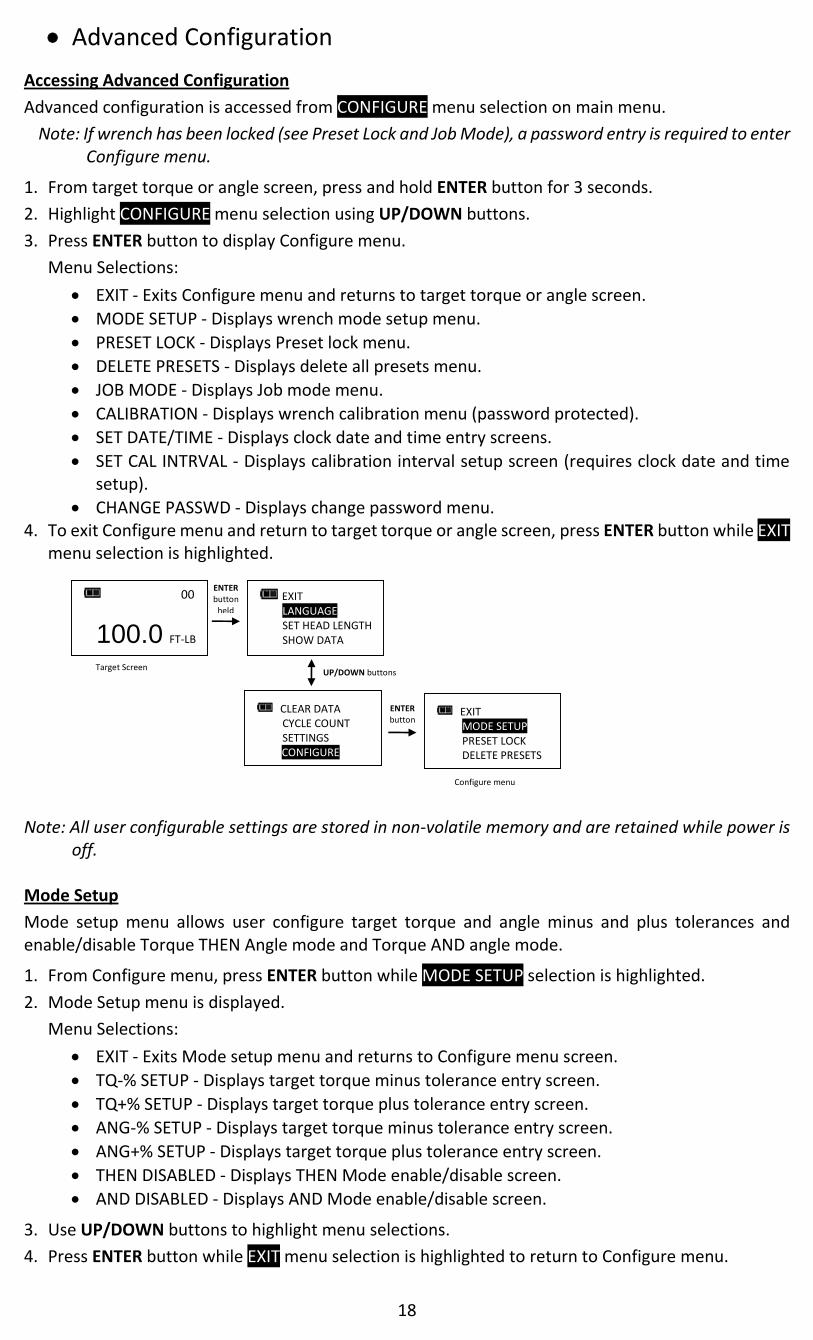
Accessing Advanced Configuration
Advanced configuration is accessed from CONFIGURE menu selection on main menu.
Note: If wrench has been locked (see Preset Lock and Job Mode), a password entry is required to enter Configure menu.
1. From target torque or angle screen, press and hold ENTER button for 3 seconds.
2. Highlight CONFIGURE menu selection using UP/DOWN buttons.
3. Press ENTER button to display Configure menu.
Menu Selections:
EXIT - Exits Configure menu and returns to target torque or angle screen.
MODE SETUP - Displays wrench mode setup menu.
PRESET LOCK - Displays Preset lock menu.
DELETE PRESETS - Displays delete all presets menu.
JOB MODE - Displays Job mode menu.
CALIBRATION - Displays wrench calibration menu (password protected).
SET DATE/TIME - Displays clock date and time entry screens.
SET CAL INTRVAL - Displays calibration interval setup screen (requires clock date and time setup).
CHANGE PASSWD - Displays change password menu. 4. To exit Configure menu and return to target torque or angle screen, press ENTER button while EXIT
menu selection is highlighted.
Note: All user configurable settings are stored in non-volatile memory and are retained while power is
off. Mode Setup
Mode setup menu allows user configure target torque and angle minus and plus tolerances and enable/disable Torque THEN Angle mode and Torque AND angle mode.
1. From Configure menu, press ENTER button while MODE SETUP selection is highlighted.
2. Mode Setup menu is displayed.
Menu Selections:
EXIT - Exits Mode setup menu and returns to Configure menu screen.
TQ-% SETUP - Displays target torque minus tolerance entry screen.
TQ+% SETUP - Displays target torque plus tolerance entry screen.
ANG-% SETUP - Displays target torque minus tolerance entry screen.
ANG+% SETUP - Displays target torque plus tolerance entry screen.
THEN DISABLED - Displays THEN Mode enable/disable screen.
AND DISABLED - Displays AND Mode enable/disable screen.
3. Use UP/DOWN buttons to highlight menu selections.
4. Press ENTER button while EXIT menu selection is highlighted to return to Configure menu.
00
100.0 FT-LB
Target Screen
CLEAR DATA CYCLE COUNT SETTINGS CONFIGUREs
UP/DOWN buttons
EXIT MODE SETUPs PRESET LOCK DELETE PRESETS
EXIT LANGUAGE SET HEAD LENGTH SHOW DATA
ENTER button
held
ENTER button
Configure menu

19
Setting Target Tolerances
This function will allow user to set plus and minus tolerances for torque and angle targets.
Note: These tolerances are used for manual modes only. Preset tolerances are defined by Minimum and Maximum values.
1. From Mode Setup menu, use UP/DOWN buttons to highlight tolerance selection to setup (TQ-%, TQ+%, ANG-% ANG+%) then press ENTER button.
2. Tolerance screen is displayed.
3. Use UP/DOWN buttons to change tolerance value. Range is 0 to 10% (factory default for minus tolerance is 0% and 4% for plus tolerance).
4. Press ENTER button to accept selection and exit to Mode Setup menu.
Note: Green progress lights turn on at target minus -% TOL.
Note: Red progress lights turn on above target plus +% TOL.
Note: Plus tolerance is added to minimum Preset value to define initial maximum value when a Preset is first added.
Enable/Disable Torque THEN Angle Mode
This function will allow user to enable or disable Torque THEN Mode.
1. From Mode Setup menu, use UP/DOWN buttons to highlight THEN DISABLED (factory default) selection then press ENTER button.
2. TQ THEN ANGLE enable/disable screen is displayed.
3. Use UP/DOWN buttons to select ENABLE or DISABLE selection.
4. Press ENTER button to accept selection and exit to Mode Setup menu.
Note: Menu selection indicates current configuration (ENABLED or DISABLED).
EXIT TQ-% SETUP TQ+% SETUP ANG-% SETUP
EXIT MODE SETUPs PRESET LOCK DELETE PRESETS
ENTER button
Configure menu Mode Setup menu
EXIT TQ-% SETUP TQ+% SETUP ANG-% SETUP
UP/DOWN buttons
TORQUE -TOL%
0
TQ-% SETUP TQ+% SETUP ANG-% SETUP ANG+% SETUP
ENTER button
ANGLE +TOL%
4 ENTER button
EXIT TQ-% SETUP TQ+% SETUP ANG-% SETUP
UP/DOWN buttons
TQ+% SETUP ANG-% SETUP ANG+% SETUP THEN DISABLED
TQ THEN ANGLE ENABLE DISABLE
ENTER button
UP/DOWN buttons
TQ THEN ANGLE ENABLE DISABLE
ENTER button
ENTER button
TQ+% SETUP ANG-% SETUP ANG+% SETUP THEN ENABLED
TQ+% SETUP ANG-% SETUP ANG+% SETUP THEN DISABLED

20
Torque THEN Angle Mode
Torque THEN Angle mode is setup by first setting a target torque and units then a target angle before selecting Torque THEN Angle mode. In Torque THEN Angle mode, when applied torque reaches target torque, wrench automatically switches to angle mode for angle measurement. Progress lights indicate applied torque progress while torque is measured and angle when angle is measured. If torque is below target torque when angle reaches target angle, green progress lights will not turn on and if angle exceeds maximum angle, red progress lights turn on indicating a potential problem with fastener.
1. From target torque screen, use UP/DOWN buttons to set target torque and UNITS button to select torque measurement units then press ENTER button.
2. Angle target screen is displayed. Use UP/DOWN buttons to set target angle then press ENTER button.
3. Torque THEN Angle mode screen is displayed.
4. Apply torque until target is reached then rotate wrench to target angle.
Note: UNITS button can be used to select torque units while on Torque THEN Angle screen.
Note: Torque cycle is not recorded in memory unless both torque and angle reach targets.
Note: Red progress lights turn on if torque exceeds 110% of wrench full scale or if angle exceeds target + plus tolerance while in manual mode.
Note: Torque THEN Angle Presets are entered by pressing and holding Units button while on Torque THEN Angle screen. MAXIMUM TORQUE defaults to full range plus 10%. Refer to "Adding a Torque Preset" and "Adding an Angle Preset" in Basic section for parameter entry.
Enable/Disable Torque AND Angle Mode
This function will allow user to enable or disable Torque AND Mode.
1. From Mode Setup menu, use UP/DOWN buttons to highlight AND DISABLED (factory default) selection then press ENTER button.
2. TQ AND ANGLE enable/disable screen is displayed.
3. Use UP/DOWN buttons to select ENABLE or DISABLE selection.
4. Press ENTER button to accept selection and exit to Mode Setup menu.
Note: Menu selection indicates current configuration (ENABLED or DISABLED).
EXIT TQ-% SETUP TQ+% SETUP ANG-% SETUP
UP/DOWN buttons
ANG-% SETUP ANG+% SETUP THEN DISABLED AND DISABLED
TQ AND ANGLE ENABLE DISABLE
ENTER button
UP/DOWN buttons
TQ AND ANGLE ENABLE DISABLE
ENTER button
ENTER button
ANG-% SETUP ANG+% SETUP THEN DISABLED AND ENABLED
ANG-% SETUP ANG+% SETUP THEN DISABLED AND DISABLED
ENTER button
00
45°
00 TQ: 100.0 FT-LB THEN AN: 45°
UP/DOWN buttons UP/DOWN buttons
00
100.0 FT-LB
ENTER button
Torque THEN Angle Screen

21
Torque AND Angle Mode
Torque AND Angle mode is setup by first setting a target torque and units then a target angle before selecting Torque AND Angle mode. In Torque AND Angle mode, torque and angle are measured simultaneously. Yellow progress lights track torque measurement. When both torque and angle reach their targets, green progress lights turn on and torque and angle data record is stored. If either of measurements exceed their upper tolerance, red progress lights turn on.
1. From target torque screen, use UP/DOWN buttons to set target torque and UNITS button to select torque measurement units then press ENTER button.
2. Angle target screen is displayed. Use UP/DOWN buttons to set target angle then press ENTER button until Torque AND Angle mode screen is displayed.
3. Apply torque and rotate wrench until both targets are reached.
Note: UNITS button can be used to select torque units while on Torque AND Angle screen.
Note: Torque THEN Angle Presets are entered by pressing and holding Units button while on Torque THEN Angle screen. Refer to "Adding a Torque Preset" and "Adding an Angle Preset" in Basic section for parameter entry.
Note: Torque cycle is not recorded in memory unless both torque and angle reach targets.
Note: Red progress lights turn on if torque exceeds target + plus tolerance or if angle exceeds target + plus tolerance while in manual mode.
Note: Red progress lights turn on if torque exceeds maximum torque or if angle exceeds maximum angle in Preset mode.
Preset Lock
Preset Lock function allows user to lock wrench so that only configured presets are accessible. No other presets can be configured and manual target torque and angle modes are not accessible when locked.
Note: Password entry is required to enable Preset Lock. When locked, password entry is required to re-enter Configure menu (refer to ControlTech™ Calibration manual for default password).
1. From Configure menu, use UP/DOWN buttons to highlight PRESET LOCK selection then press ENTER button.
2. Preset Lock enable/disable screen is displayed.
3. Use UP/DOWN buttons to select LOCK or UNLOCK selection.
4. Press ENTER button to accept selection and exit to Configure menu.
00
100.0 FT-LB
ENTER button
Torque AND Angle Screen UP/DOWN buttons
00
45°
UP/DOWN buttons
ENTER button
00 TQ: 100.0 FT-LB AND AN: 45°
ENTER button
ENTER PASSWD
0 0 0 0 0
Password screen
UP/DOWN buttons
UP/DOWN buttons
PRESET LOCK LOCK UNLOCK
ENTER button
UP/DOWN buttons
PRESET LOCK LOCK UNLOCK
ENTER button
ENTER button
EXIT MODE SETUPs PRESET LOCK DELETE PRESETS
Preset Lock menu
EXIT MODE SETUP PRESET LOCK DELETE PRESETS
EXIT MODE SETUP PRESET LOCK DELETE PRESETS
EXIT MODE SETUP
PRESET LOCK DELETE PRESETS
Lock icon

22
Note: If LOCK is selected without a Preset configured, following screen is displayed:
Note: When Preset Lock is enabled, Clear Memory function is disabled and displays following Locked
message if attempted:
Note: When Preset Lock is enabled, Clear Cycle count function is disabled and displays Locked message
if attempted.
Preset Unlock
When Preset Lock is enabled, a password is required to access Configure menu. Refer to ControlTech™ Calibration Manual for Configure password.
1. From target torque or angle screen, press and hold ENTER button for 3 seconds.
2. Highlight CONFIGURE menu selection using UP/DOWN buttons.
3. Press ENTER button to display Password screen.
4. Follow password entry procedure found in ControlTech™ Calibration manual.
Delete Presets
Delete Presets function allows user to delete all presets at once.
1. From Configure menu, use UP/DOWN buttons to highlight DELETE PRESET selection then press ENTER button.
2. Delete Presets confirmation screen is displayed.
3. Use UP/DOWN buttons to select YES or NO selection.
4. Press ENTER button to accept selection and exit to Configure menu.
Note: If Delete Presets is selected without a Preset configured, following screen is displayed:
LOCKED
PRESS TO CONT.
NO PRESETS PRESS TO CONT.
NO PRESETS
PRESS TO CONT.
UP/DOWN buttons
DELETE PRESETS YES NO
ENTER button
UP/DOWN buttons
EXIT MODE SETUPs PRESET LOCK DELETE PRESETS
Delete Presets menu
EXIT MODE SETUP PRESET LOCK DELETE PRESETS
00
CLEAR DATA CYCLE COUNT
SETTINGS CONFIGUREs
UP/DOWN buttons
ENTER PASSWD
0 0 0 0 0
EXIT LANGUAGE
SET HEAD LENGTH SHOW DATA
ENTER button
held
ENTER button
Password screen
92 DEG

23
Job Mode
Job Mode function allows user to enable or disable wrench preset Job mode. When in Job mode, wrench executes presets in order configured and automatically switches to next preset when batch count reaches zero. Wrench is locked and Preset lock icon is displayed when Job mode is enabled.
Note: Password entry is required to enable Job Mode. When enabled, password entry is required to re-enter Configure menu (refer to ControlTech™ Calibration manual for default password).
1. From Configure menu, use UP/DOWN buttons to highlight JOB MODE selection then press ENTER button.
2. Job Mode enable/disable screen is displayed.
3. Use UP/DOWN buttons to select ENABLE or DISABLE.
4. Press ENTER button to accept selection and exit to Configure menu.
Note: Text "JOB" is displayed between PSET number and batch count when enabled.
Calibration
Calibration menu is password protected. Refer to ControlTech™ Calibration manual.
Setting Date and Time
Set Date/Time function allows user to set real-time-clock date and time for time stamping data records, recording last calibration date and notifying user of an expired calibration interval.
Note: When date and time is set for first time, In-Service date is also set and is used for calculating initial calibration interval (see "Setting Calibration Interval" in Advanced Configuration section).
1. From Configure menu, use UP/DOWN buttons to highlight SET DATE/TIME selection then press ENTER button.
2. SET DATE screen is displayed with year highlighted.
3. Use UP/DOWN buttons to set year then press ENTER button to highlight month.
4. Use UP/DOWN buttons to set month then press ENTER button to highlight day.
5. Use UP/DOWN buttons to set day then press ENTER button.
6. SET TIME screen is displayed with hour highlighted.
PSET 01 JOB 00
100.0 FT-LB
PRESET LOCK DELETE PRESETS JOB MODE CALIBRATION
ENTER PASSWD
0 0 0 0 0
Password screen
UP/DOWN buttons
ENTER button
UP/DOWN buttons
JOB MODE ENSABLE DISABLE
ENTER button
UP/DOWN buttons
JOB MODE ENABLE DISABLE
ENTER button
ENTER button
EXIT MODE SETUPs PRESET LOCK DELETE PRESETS
Job Mode menu
MODE SETUP PRESET LOCK DELETE PRESETS JOB MODE
MODE SETUP PRESET LOCK DELETE PRESETS JOB MODE
EXIT MODE SETUP
DELETE PRESETS JOB MODE
Lock icon

24
7. Use UP/DOWN buttons to set hour then press ENTER button to highlight minutes.
8. Use UP/DOWN buttons to set minutes then press ENTER button to highlight seconds.
9. Use UP/DOWN buttons to set seconds then press ENTER button.
10. Clock is set and Configure menu is displayed.
Note: Year selection will scroll up from 2014. Month selection will scroll from 1 to 12. Day selection will scroll from 1 to 31.
Note: Hour selection will scroll through 0 to 23. Minute and Second selections will scroll through 0 to 59.
Note: If batteries are removed from wrench for longer than 20 minutes, clock will revert to default settings and must be re-entered at power on.
Setting Calibration Interval
This function will allow user to set calibration interval for when "CAL NEEDED" message will be displayed. 1. From Configure menu, use UP/DOWN buttons to highlight SET CAL INTRVAL selection then press
ENTER button.
2. CAL INTERVAL screen is displayed.
3. Use UP/DOWN buttons to change calibration interval.
Selectable Intervals:
12 MON (factory default)
6 MON
3 MON
DISABLED
4. Press ENTER button to accept selection and exit to Configure menu.
Note: Clock Date and Time must be set before calibration interval will function. If batteries are removed from wrench for longer than 20 minutes, clock will revert to default settings and must be re-entered at power on.
ENTER button
CAL INTRVAL 12 MON EXIT
JOB MODE CALIBRATION SET DATE/TIME SET CAL INTRVAL
ENTER button
UP/DOWN buttons
CAL INTRVAL DISABLED EXIT
SET DATE 2014/01/01 YR MON DAY
SET DATE 2014/01/01 YR MON DAY
SET DATE 2014/01/01 YR MON DAY
DELELTE PRESETS JOB MODE CALIBRATION SET DATE/TIME
ENTER button
UP/DOWN buttons
ENTER button
UP/DOWN buttons
ENTER button
UP/DOWN buttons
SET TIME 12 : 00 : 00 HR MIN SEC
SET TIME 12 : 00 : 00 HR MIN SEC
SET TIME 12 : 00 : 00 HR MIN SEC
UP/DOWN buttons
ENTER button
UP/DOWN buttons
ENTER button
UP/DOWN buttons
ENTER button
ENTER button

25
Note: Calibration interval is calculated from either IN-Service Date or last Calibration date (see SHOW INFO menu) depending on which is more recent date. When clock Date is greater than IN-Service or Last Calibration date, plus Cal Interval, "CAL NEEDED" message will be displayed on power up and after a re-zero. Pressing ENTER button will continue to target menu. Applying torque while "CAL NEEDED" message is displayed will immediately display torque or angle measurement and return to target menu when released.
Note: As an alternative to calibration interval, a Calibration Cycle Counter is provided in Calibration menu (Refer to ControlTech™ Calibration manual regarding Calibration menu). Each time a measurement cycle reaches target torque, calibration cycle counter is incremented. When torque is recalibrated, calibration counter is automatically reset to zero. User can disable calibration interval check and use number of cycles since last calibration to decide when to recalibrate.
Note: If an invalid date is entered and Calibration interval is enabled, an unintended "CAL NEEDED" message may be displayed. Either disable calibration interval or enter a correct date.
Change Password
Change Password function allows user to change password to a new password. Default password is required to initially change password. Refer to ControlTech™ Calibration Manual for default password.
1. From Configure menu, use UP/DOWN buttons to highlight CHANGE PASSWD selection then press ENTER button.
2. Initial password entry screen is displayed.
3. Enter default password if changing for first time, otherwise enter current user password using UP/DOWN buttons to change each digit followed by ENTER button.
4. Change password entry screen is displayed.
5. Enter new password using UP/DOWN buttons to change each digit followed by ENTER button.
6. Confirm password entry screen is displayed.
7. Re-enter new password using UP/DOWN buttons to change each digit followed by ENTER button.
Note: Pressing POWER button at any time aborts password change sequence.
Note: If an invalid password is entered during confirmation step, Invalid Password Match screen is displayed and new password is not accepted.
UP/DOWN buttons
ENTER PASSWD 0 0 0 0 0
ENTER button
UP/DOWN buttons
ENTER button
EXIT MODE SETUPs PRESET LOCK DELETE PRESETS
New password entry screen
CALIBRATION SET DATE/TIME SET CAL INTRVAL CHANGE PASSWD
CHANGE PASSWD 0 0 0 0 0
Previous password entry screen
UP/DOWN buttons
ENTER button
Confirm password screen
CONFIRM PASSWD 0 0 0 0 0
UP/DOWN buttons
INVALID PASSWD MATCH PRESS TO CONT.

26
Troubleshooting Note: If any of following issues persist, return wrench to an authorized Snap-on repair center.
Issue Possible Cause Resolution
Wrench does not turn on when POWER button pressed.
Dead/No batteries Replace batteries
Software glitch Cycle power using end-cap
Torque reading out of spec. Calibration required Recalibrate
Incorrect head length entered
Enter correct offset head length
Wrench did not retain settings while batteries were removed.
Batteries removed before setting were saved in non-volatile memory.
Clear data, re-enter settings and press and hold POWER button to power down wrench before removing batteries.
Low battery Press ENTER button to continue using wrench and replace batteries soon.
Dead battery Press POWER button to turn off wrench and replace batteries.
Torque applied while zeroing Remove torque and re-zero
Wrench over torqued Recalibrate
Wrench improperly calibrated
Recalibrate
Torque sensor failure Return to Factory
Wrench moving during zeroing
Place wrench on stable surface
Gyro unstable Return to Factory
ENTER button pressed during angle zeroing (Aborted zeroing to access menus)
Press POWER button to re-zero
Over 125% of full scale torque applied
Cycle power using POWER button and recalibrate
Wrench rotated too fast during angle measurement
Press POWER button to re-zero
Calibration interval exceeded or invalid date entered with calibration interval enabled
Calibrate wrench or press ENTER to continue. Disable calibration interval if not required.
Memory error Clear data memory
Torque uncalibrated Calibrate torque
Angle uncalibrated Calibrate angle

27
USE OF ADAPTORS, EXTENSIONS AND UNIVERSALS Anytime an adaptor, extension or universal is used with a torque wrench in such a way that fastener distance is different than torque wrench square drive distance at calibration, an adjustment to head length is required to get a proper fastener torque reading. When using wobble extension or a universal, do not exceed more than 15 degrees of offset from perpendicular drive. Do not use a long extension with flex-drive at full flex.
CALIBRATION Contact your Snap-on sales representative for calibration services or refer to ControlTechTM Calibration Manual.
CERTIFICATION This torque-angle wrench was calibrated at factory using angular displacement and torque measurement instruments that are traceable to National Institute of Standards and Technology (N.I.S.T.). Torque parameters comply with ISO 6789:2003 and ASME B107:300-2010 (B107.29). Note: no U.S. or International Standards exist for angle wrenches.
MAINTENANCE / SERVICE Clean wrench by wiping with a damp cloth. DO NOT use solvents, thinners or carburetor cleaners. DO NOT immerse in anything. Service and repairs are to be done by Snap-on Service Centers only. Contact your Snap-on Tools representative. Ratchet head repair kits can be ordered from a Snap-on Representative. NOTES: - If display shows persistent "TORQUE ZERO ERROR" at power on, wrench is damaged and
must be returned for repair - If display shows “ANGLE ERROR” in angle mode, fastener rotation speed has exceeded
capacity of wrench. - Wrench must be held still during angle zeroing. Motion is indicated by alternating dashes “-
-” on display - Remove battery when stored for extended periods (Note: clock will revert to default
settings).
IMPORTANT! Calibration events are recorded in wrench memory which provides evidence to void factory certification.

28
Battery Replacement Note: When replacing batteries, real-time-clock will maintain date and time for 20 minutes. Note: Turn End Cap counter-clockwise to unscrew.
Replace 240 models with three "AAA" cells only.
Batteries should be installed in carrier prior to carrier installation into wrench. Battery negative contacts should be oriented with carrier springs.
Replace all other models with three "AA" cells only. Note: When Replace Battery screen is displayed wrench will no longer operate until batteries are
replaced. Only POWER button functions which immediately turns off wrench.
Memory Indicators
DATA IN MEMORY
MEMORY FULL
MEMORY ERROR
Less than 1500 torque and angle records stored in memory.
1500 torque or angle records stored in memory. New records will not be recorded until memory is cleared.
Memory read or write error.
UNSCREW END CAP INSERT NEW CELLS POSITIVE (+) END INTO HANDLE FIRST
LOW BATTERY
100% BATTERY LEVEL
50% BATTERY LEVEL
LOW BATTERY
REPLACE BATTERY REPLACE BATTERY

29
This page intentionally left blank

30

AUTHORIZED SNAP-ON REPAIR CENTERS
USA
Eastern Repair Center 6320 Flank Drive Harrisburg, PA 17112 Phone: 717-652-7914 Fax: 717-652-7123 Northern Repair Center 3011 E. State Rt. 176, Dock A Crystal Lake, Il 60014 Phone: 815-479-6850 Fax: 815-479-6857 Western Repair Center 3602 Challenger Way Carson City, NV 89706-0753 Phone: 775-883-8585 Fax: 775-883-8590 CANADA Western Repair Centre 7403-48 Street SE Calgary, Alberta Canada, T2C-4H6 Phone: 403-720-0525 Fax: 403-720-0524
20-3101-SNAP-ON REV. H
INTERNATIONAL
United Kingdom Repair Center Telford Way Telford Way Industrial Estate Kettering, Northants NN16 8UN England Phone: 44-1-536-413855 Fax: 44-1-536-413900 Australia Repair Centre Snap-on Tools Australia PTY.LTD 80 Holbeche Road Arndell Park NSW 2148 Australia Phone: 61-2-9837-9155 Fax: 61-2-9837-9192 Singapore Repair Center Snap-on Tools Singapore Pte Ltd 25 Tagore Lane, #01-01, Singapore, 787602 Phone: 65-64515570 Fax: 65-64515574 Japan Repair Center Snap-on Tools Japan K.K. 2-1-6 Shinkiba Koto-ku, Tokyo 136-0082 Japan Phone: 81-3-5463-1280 Fax: 81-3-5463-1284 Snap-on/SUN De Mexico S.A. De C.V. Avenida Presidente Juarez No. 2016 Col Los Reyes Zona Industrial Tlalnepantla Edo De Mexico CP54070 MEXICO Phone: 52-55-53903122 Fax: 52-55-53903259
Snap-on Tools Company Kenosha, WI 53141-1410 USA
Printed in USA 15-08