controls development for hybrid systems dr. david tucker, netl€¦ · controls development for...
TRANSCRIPT

Controls Development for Hybrid Systems
Dr. David Tucker, NETL
We are completing system analyses required
for the operable design of two representative
systems: FC/GT and FC/ICE.
We are developing and testing both
supervisory control and dynamic control
algorithms in advance of the fabrication of
proposed cycles using NETL’s cyber-
physical systems.
Project Vision

Project OverviewFed. funding: $1.7 M
Length 24 mo.
AK Supply Inc.
Hybrid Control
Strategy (CS)
NETL HyperSA optimize
thermal integration
CPS reformer, Hyper,
SOFC/ICE
Implement CS Test hybrids
Ames LabImplement CS
and test hybrids
Start up Nominal ops Shutdown
test and optimize controls
CPS
GTRIModels
optimization and validation
Real Time Models
AK SupplyHardware
component designs
Designs modifications

Innovation and Objectives
Task outline, technical objectivesDevelopment of control strategies
applicable to both SOFC/GT and
SOFC/ICE hybrid power systems using
a cyber-physical approach
Tech-to-Market objectives
• Support the other teams by
ensuring viable dynamic and
supervisory control strategies
Layout for the CPS reformer Potential Cycle Modifications

3
FC/ICE Hybrid Cycle Evaluation

4
FC/ICE Hybrid Cycle Evaluation
LHV-FC Fuel
LHV-C1 Fuel
𝒎 𝑻𝑹
𝑻
𝑪𝒑𝒅𝑻GT Exhaust
𝒎 𝑻𝑹
𝑻
𝑪𝒑𝒅𝑻ICE Exhaust
𝒎 𝑻𝑹
𝑻
𝑪𝒑𝒅𝑻
ICE Inlet Air Cooling
𝒎 𝑻𝑹
𝑻
𝑪𝒑𝒅𝑻
ICE Inlet Fuel Cooling
FC Electric Power
ICE Electric Power

5
FC/ICE Hybrid Cycle Evaluation
Topping and Bottoming Cycle

6
FC/ICE Cycle: Basic Configuration, No Anode Recycle

7
Hybrid System Efficiency and Stack Size as a Function of SOFC Fuel Utilization and
Reformer Operating Temperature
FC/ICE Cycle: Basic Configuration, No Anode Recycle

8
SOFC/ICE Configurations Autothermal Ref. Reformer at the Anode Exhaust
Anode Exhaust Cooling ICE-1 ICE-2a ICE-2b ICE-2c
Preheating CH4 to reformer --- --- ---
Steam to reformer
Add. cooling water
Reformer ---
Preheating reformate to anode --- --- ---
Turbine Inlet ICE-1 ICE-2a ICE-2b ICE-2c
ICE exhaust + Turbine inlet ? - -
Reformer Steam Generation ICE-1 ICE-2a ICE-2b ICE-2c
Intercooler ---
Turbine exhaust --- --- ---
ICE exhaust ---
Anode exhaust
Cathode exhaust --- --- ---
Cathode Exhaust ICE-1 ICE-2a ICE-2b ICE-2c
Preheating reformate to anode ---
Preheating cathode inlet air
Steam to reformer --- --- ---
FC/ICE Cycle: Hybrid Cycle Evaluation

9
FC/ICE Cycle: Comparison, ICE Cycle-2a

10
FC/ICE Cycle: Comparison, ICE Cycle-2b

11
FC/ICE Cycle: Comparison, ICE Cycle-2c

12
FC/ICE Cycle: Hybrid Cycle Evaluation (4 Cycles)
Hybrid System Efficiency and Stack Size as a Function of SOFC Fuel Utilization and
Reformer Operating Temperature

13
FC/ICE Cycle: Basic Configuration, With Anode Recycle

FC/ICE Cycle: Basic Configuration, With Anode Recycle
14
Hybrid System Efficiency and Stack Size in SOFC/ICE Cycle as a Function of SOFC
Fuel Utilization and Anode Recycle Rate to Reformer at 800K and 1000K Reforming
Temperature

15
FC/ICE Cycle: Summary
• Behaves as a Bottoming Cycle
• Thermal Integration have small affects on system
efficiency
• High fuel utilization operation is needed to achieve high
efficiency.
• Anode Recycle increases efficiency. May be the key to
achieve 70% efficient cycle.

16
FC/GT Hybrid Cycle Evaluation

FC/GT Hybrid Cycle Evaluation
17
FC Electric Power
𝒎 𝑻𝑹
𝑻
𝑪𝒑𝒅𝑻
GT Electric Power
RecuperatorExhaust
LHV-FC Fuel
LHV-C1 Fuel

FC/GT Cycle: Autothermal Reformer, No Anode Recycle
18

FC/GT Cycle: Autothermal Reformer, No Anode Recycle
19
Hybrid System Efficiency and Stack Size as a Function of SOFC Fuel Utilization and
Reformer Operating Temperature
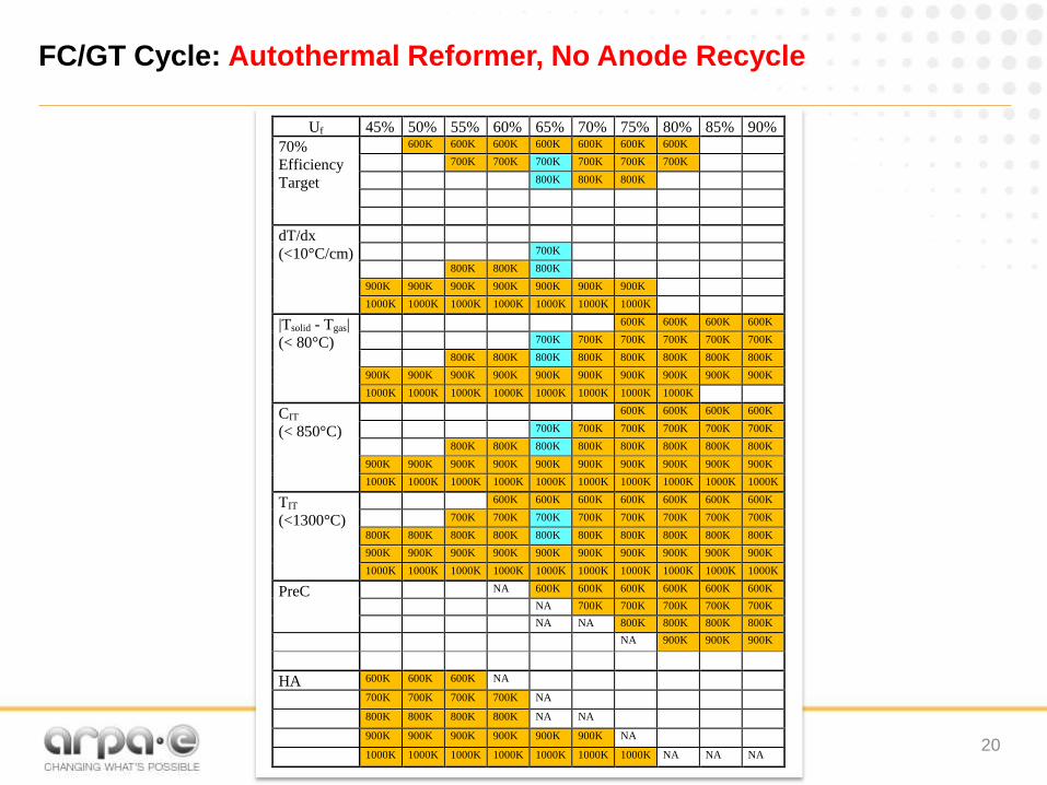
FC/GT Cycle: Autothermal Reformer, No Anode Recycle
20
Uf 45% 50% 55% 60% 65% 70% 75% 80% 85% 90%
70%
Efficiency
Target
600K 600K 600K 600K 600K 600K 600K
700K 700K 700K 700K 700K 700K
800K 800K 800K
dT/dx
(<10°C/cm)
700K
800K 800K 800K
900K 900K 900K 900K 900K 900K 900K
1000K 1000K 1000K 1000K 1000K 1000K 1000K
|Tsolid - Tgas|
(< 80°C)
600K 600K 600K 600K
700K 700K 700K 700K 700K 700K
800K 800K 800K 800K 800K 800K 800K 800K
900K 900K 900K 900K 900K 900K 900K 900K 900K 900K
1000K 1000K 1000K 1000K 1000K 1000K 1000K 1000K
CIT
(< 850°C)
600K 600K 600K 600K
700K 700K 700K 700K 700K 700K
800K 800K 800K 800K 800K 800K 800K 800K
900K 900K 900K 900K 900K 900K 900K 900K 900K 900K
1000K 1000K 1000K 1000K 1000K 1000K 1000K 1000K 1000K 1000K
TIT
(<1300°C)
600K 600K 600K 600K 600K 600K 600K
700K 700K 700K 700K 700K 700K 700K 700K
800K 800K 800K 800K 800K 800K 800K 800K 800K 800K
900K 900K 900K 900K 900K 900K 900K 900K 900K 900K
1000K 1000K 1000K 1000K 1000K 1000K 1000K 1000K 1000K 1000K
PreC NA 600K 600K 600K 600K 600K 600K
NA 700K 700K 700K 700K 700K
NA NA 800K 800K 800K 800K
NA 900K 900K 900K
HA 600K 600K 600K NA
700K 700K 700K 700K NA
800K 800K 800K 800K NA NA
900K 900K 900K 900K 900K 900K NA
1000K 1000K 1000K 1000K 1000K 1000K 1000K NA NA NA

FC/GT Cycle: Autothermal Reformer, With Anode Recycle
21

FC/GT Cycle: Autothermal Reformer, With Anode Recycle
22
Hybrid System Efficiency in SOFC/GT Cycle as a Function of Anode Recycle Rate to Reformer,
SOFC Fuel Utilization and Reformer Operating Temperature

FC/GT Cycle: Autothermal Reformer, With Anode Recycle
23
SOFC Stack Size in SOFC/GT Cycle as a Function of Anode Recycle Rate to Reformer,
SOFC Fuel Utilization and Reformer Operating Temperature

FC/GT Cycle: Autothermal Reformer, With Anode Recycle
24

Anode Recycle Comparison
25
Reforming
Temperature
Max.
System
Efficiency
Fuel
Utilization
Max.
System
Efficiency
Fuel
Utilization
Efficiency
Gain
(% point)
Change in
SOFC Size,
(AR)
600K 73.7% 60% 74.7%60%
(10%AR)1.0% 5.2%
700K 72.9% 65% 74.8%55%
(20%AR)1.9% -3.6%
800K 71.3% 70% 75.4%50%
(40%AR)4.1% -4.6%
900K 68.4% 80% 71.3%55%
(50%AR)2.9% -7.0%
Comparison of Optimal Conditions in SOFC/GT Cycle with and without Anode recycle
0% Anode Recycle With Anode Recycle Comparison
FC/GT Cycle: Autothermal Reformer

26
FC/GT Cycle: Reformer at GT Inlet, No Anode Recycle
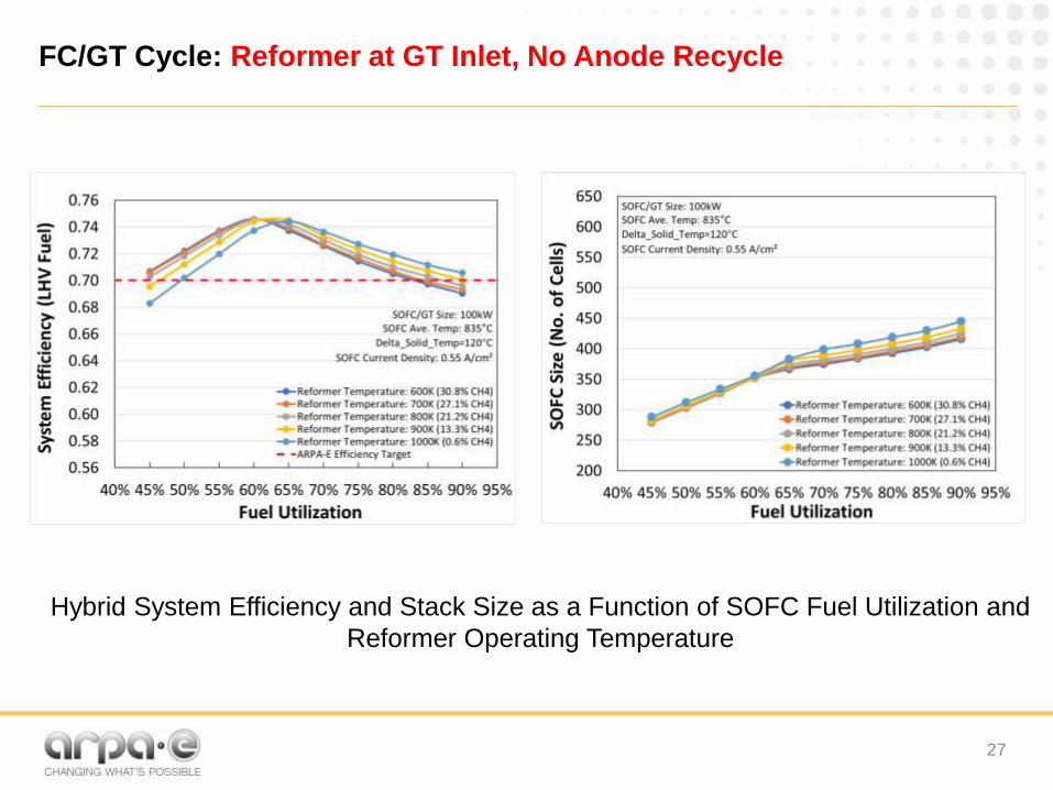
FC/GT Cycle: Reformer at GT Inlet, No Anode Recycle
27
Hybrid System Efficiency and Stack Size as a Function of SOFC Fuel Utilization and
Reformer Operating Temperature

28
FC/GT Cycle: Reformer at GT Inlet, No Anode Recycle
Uf 45% 50% 55% 60% 65% 70% 75% 80% 85% 90%
70%
Efficiency
Target
600K 600K 600K 600K 600K 600K 600K 600K
700K 700K 700K 700K 700K 700K 700K 700K
800K 800K 800K 800K 800K 800K 800K 800K 800K
900K 900K 900K 900K 900K 900K 900K 900K 900K
1000K 1000K 1000K 1000K 1000K 1000K 1000K 1000K 1000K
dT/dx
(<10°C/cm)
700K 700K
800K 800K 800K
900K 900K 900K 900K 900K
1000K 1000K 1000K 1000K 1000K 1000K 1000K
|Tsolid - Tgas|
(< 80°C)
600K 600K 600K 600K
700K 700K 700K 700K 700K
800K 800K 800K 800K 800K 800K 800K
900K 900K 900K 900K 900K 900K 900K 900K 900K 900K
1000K 1000K 1000K 1000K 1000K 1000K 1000K 1000K 1000K 1000K
CIT
(< 850°C)
600K 600K 600K 600K 600K
700K 700K 700K 700K 700K 700K
800K 800K 800K 800K 800K 800K 800K
900K 900K 900K 900K 900K 900K 900K 900K 900K 900K
1000K 1000K 1000K 1000K 1000K 1000K 1000K 1000K 1000K 1000K
TIT
(<1300°C)
600K 600K 600K 600K 600K 600K 600K 600K
700K 700K 700K 700K 700K 700K 700K 700K
800K 800K 800K 800K 800K 800K 800K 800K 800K 800K
900K 900K 900K 900K 900K 900K 900K 900K 900K 900K
1000K 1000K 1000K 1000K 1000K 1000K 1000K 1000K 1000K 1000K

29
FC/GT Cycle: Reformer at GT Inlet, With Anode Recycle

FC/GT Cycle: Reformer at GT Inlet, With Anode Recycle
30
Hybrid System Efficiency in SOFC/GT Cycle as a Function of Anode Recycle Rate to Reformer,
SOFC Fuel Utilization and Reformer Operating Temperature

FC/GT Cycle: Reformer at GT Inlet, With Anode Recycle
31
Stack Size in SOFC/GT Cycle as a Function of Anode Recycle Rate to Reformer,
SOFC Fuel Utilization and Reformer Operating Temperature

32
FC/GT Cycle: Reformer at GT Inlet, With Anode Recycle
Uf 45% 50% 55% 60% 65% 70% 75% 80% 70%
Efficiency
Target
700K (All)
700K (All)
700K (All)
700K (All)
700K (All)
700K (All)
NA NA
800K (All)
800K (All)
800K (All)
800K (All)
800K (All)
800K (All)
800K (All)
800K (All)
900K
(AR)
900K
(All)
900K
(All)
900K
(All)
900K
(All)
900K
(All)
900K
(All)
dT/dx
(<10°C/cm)
700K
(All)
700K
(All)
700K
(All)
700K
(15,
20%)
NA NA
800K (All)
800K (All)
800K (All)
800K (20-
40%)
800K (40%)
900K
(All)
900K
(All)
900K
(All)
900K
(All)
900K
(All)
900K
(20,
30%)
900K
(40,
50%)
(Tsolid – Tgas)
(< 80°C)
700K (All)
NA NA
800K (40%)
800K (30,
40%)
800K (All)
800K (All)
800K (All)
800K (All)
800K (All)
900K
(All)
900K
(All)
900K
(All)
900K
(All)
900K
(All)
900K
(All)
900K
(All)
900K
(All)
CIT
(< 850°C)
700K (All)
700K (All)
NA NA
800K (20-
40%)
800K (All)
800K (All)
800K (All)
800K (All)
800K (All)
900K
(All)
900K
(All)
900K
(All)
900K
(All)
900K
(All)
900K
(All)
900K
(All)
900K
(All)
TIT
(<1300°C)
700K
(AR)
700K
(All)
700K
(All)
NA NA
800K (40%)
800K (AR)
800K (All)
800K (All)
800K (All)
800K (All)
900K (50%)
900K (30-
50%)
900K (AR)
900K (All)
900K (All)
900K (All)
900K (All)
STCR>2:1 700K
(All)
700K
(All)
700K
(All)
700K
(All)
700K
(All)
700K
(All)
NA NA
800K (All)
800K (All)
800K (All)
800K (All)
800K (All)
800K (All)
800K (All)
800K (All)
900K
(AR)
900K
(AR)
900K
(AR)
900K
(AR)
900K
(AR)
900K
(AR)
900K
(AR)
900K
(AR)

33
FC/GT Cycle: Summary
• Thermal Integration
• Expands cycle capabilities
• Enhances system flexibility
• Obviates the need for Anode Recycle
• Requires complicated control strategies
• On-anode reforming is not justified if thermal integration
can be realized
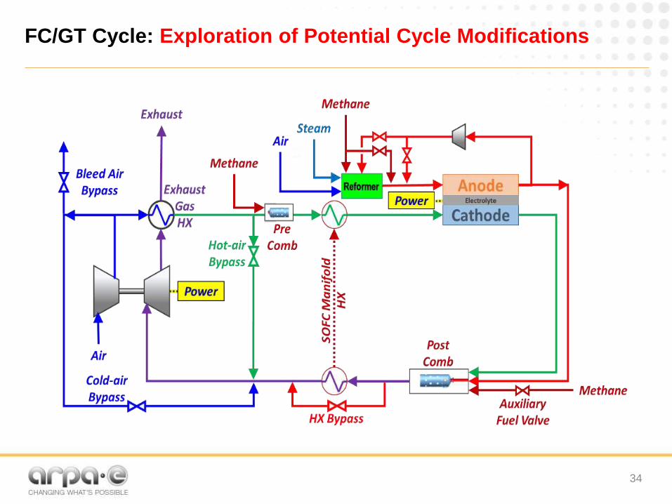
FC/GT Cycle: Exploration of Potential Cycle Modifications
34

FC/ICE Cycle: Exploration of Potential Cycle Modifications
35

Real Time Reformer/Fuel Cell Model Reconfiguration
36
Packed bed reformer reactor

Design, Fabrication and installation of CPS Reformer
37
Preliminary design is completed for the CPS reformer.

Design, Fabrication and installation of CPS Reformer
38

Hyper Facility Modification: Internal Combustion Engine
39

Control Strategy development:Startup
40

Risks
Schedule