control of a bidirectional z-source inverter for electric
TRANSCRIPT

120 Journal of Power Electronics, Vol. 11, No. 2, March 2011
JPE 11-2-2
Control of a Bidirectional Z-Source Inverter forElectric Vehicle Applications in Different Operation
ModesOmar Ellabban†, Joeri Van Mierlo∗, and Philippe Lataire∗
†∗Dept. of Electrical Engineering and Energy Technology, Vrije Universiteit Brussel, Brussels, Belgium
Abstract
This paper proposes two control strategies for the bidirectional Z-source inverters (BZSI) supplied by batteries for electricvehicle applications. The first control strategy utilizes the indirect field-oriented control (IFOC) method to control the inductionmotor speed. The proposed speed control strategy is able to control the motor speed from zero to the rated speed with the rated loadtorque in both motoring and regenerative braking modes. The IFOC is based on PWM voltage modulation with voltage decouplingcompensation to insert the shoot-through state into the switching signals using the simple boost shoot-through control method.The parameters of the four PI controllers in the IFOC technique are designed based on the required dynamic specifications. Thesecond control strategy uses a proportional plus resonance (PR) controller in the synchronous reference frame to control the ACcurrent for connecting the BZSI to the grid during the battery charging/discharging mode. In both control strategies, a dual loopcontroller is proposed to control the capacitor voltage of the BZSI. This controller is designed based on a small signal modelof the BZSI using a bode diagram. MATLAB simulations and experimental results verify the validity of the proposed controlstrategies during motoring, regenerative braking and grid connection operations.
Key Words: Bidirectional Z-source Inverter, Grid interface, Indirect field-oriented control, Regenerative braking
I. INTRODUCTION
With increasing oil prices and global warming, automobilemanufacturers are producing more hybrid electric vehicles(HEV) and electric vehicles (EV). In hybrid and electricvehicles, the motor drive comprised of an electric motor, apower converter and an electronic controller, is the core ofthe EV propulsion system. Many research efforts have beenfocused on developing new DC/DC converters and inverterssuitable for hybrid and electric vehicles applications.
There are two basic configurations for power convertersused in HEV: one is a traditional PWM inverter powered bya battery as shown in Fig. 1, the other is an inverter plus aDC/DC converter as shown in Fig. 2. Usually a bidirectionalDC/DC converter is used. It acts as a boost converter dur-ing motoring operation to drive the traction motor for highspeed and high torque and it works as a buck converter tocapture regenerative braking energy. As a result, bidirectionalpower transfer is desirable and leads to improvements in theHEV’s efficiency for transient drive cycles. The battery voltagevariations in HEVs can be as large as 50% and depend onthe battery type. With this voltage range, a traditional PWMinverter has to be oversized to handle the full voltage and twice
Manuscript received May 10, 2009; revised Dec. 30, 2010† Corresponding Author: [email protected]
TeX: +32-2-629-29-92, Fax: +32-2-629-36-20, Vrije Univ. Brussel∗Dept. of Electrical Engineering and Energy Technology, Vrije Universiteit
Brussel, Belgium
Fig. 1. Traditional PWM inverter for HEV applications.
the current at 50% of the battery voltage to output full power.This increases the cost of the inverter. A DC/DC boosted PWMinverter can minimize the stress of the inverter with an extrabidirectional DC/DC stage; however, this increases the systemcost and complexity while reducing reliability [1].
The Z-source inverter (ZSI), as shown in Fig. 3, is anemerging topology of power electronics converters with veryinteresting properties such as buck-boost characteristics andsingle stage conversion. It has a niche for automotive appli-cations to overcome the above mentioned problems. It can:produce any desired AC output voltage, even one greater thanthe input voltage; provide ride-through during voltage sagswithout any additional circuits; improve the power factor andreduce the harmonic current and the common-mode voltage[2].
The above features make the ZSI fed adjustable speed drive(ASD) systems highly desirable and reliable when comparedto voltage source inverter (VSI) fed ASDs. A ZSI for ASD
Control of a Bidirectional Z-Source Inverter for. . . 121
Fig. 2. DC/DC boosted PWM inverter for HEV applications.
Fig. 3. Basic Z-Source inverter for HEV applications.
systems has been proposed in [3] where the features andadvantages of the ZSI fed induction motor systems over thetraditional VSI based systems were outlined. In [4], a currentmode integrated control technique (CM-ICT) using a modi-fied voltage space vector modulation (MSVM) for ZSI fedinduction motor drives has been proposed using two controlloops. An outer voltage loop controls the motor line voltagethrough a PI controller and an inner current loop regulates themotor phase current through a PI controller and a limiter toprovide the reference voltage for the MSVM block. The PIcontrollers were tuned using the Ziegler-Nichols method andthe motor line voltages and currents were sensed to providefeedback signals. In this method, the DC-link voltage is notcontrolled. In addition, there is no speed or torque control forthe induction motor.
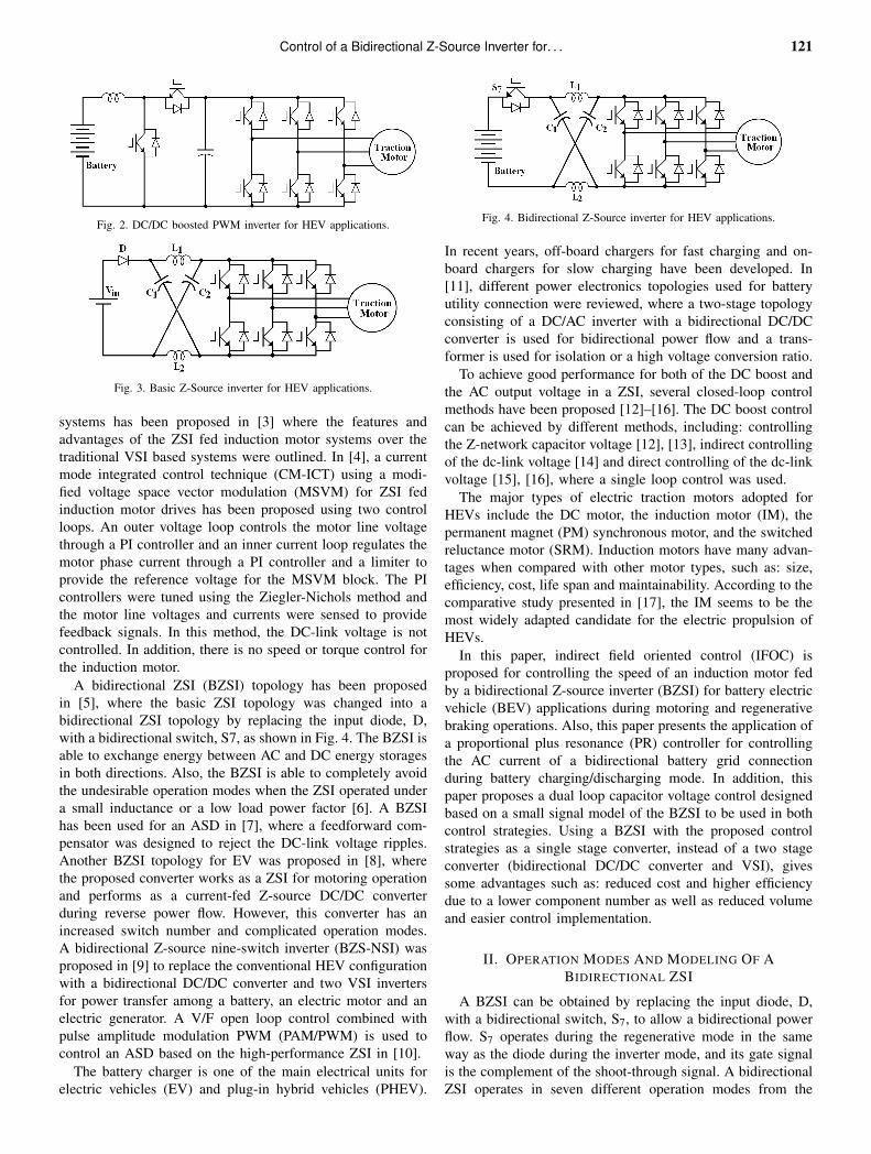
A bidirectional ZSI (BZSI) topology has been proposedin [5], where the basic ZSI topology was changed into abidirectional ZSI topology by replacing the input diode, D,with a bidirectional switch, S7, as shown in Fig. 4. The BZSI isable to exchange energy between AC and DC energy storagesin both directions. Also, the BZSI is able to completely avoidthe undesirable operation modes when the ZSI operated undera small inductance or a low load power factor [6]. A BZSIhas been used for an ASD in [7], where a feedforward com-pensator was designed to reject the DC-link voltage ripples.Another BZSI topology for EV was proposed in [8], wherethe proposed converter works as a ZSI for motoring operationand performs as a current-fed Z-source DC/DC converterduring reverse power flow. However, this converter has anincreased switch number and complicated operation modes.A bidirectional Z-source nine-switch inverter (BZS-NSI) wasproposed in [9] to replace the conventional HEV configurationwith a bidirectional DC/DC converter and two VSI invertersfor power transfer among a battery, an electric motor and anelectric generator. A V/F open loop control combined withpulse amplitude modulation PWM (PAM/PWM) is used tocontrol an ASD based on the high-performance ZSI in [10].
The battery charger is one of the main electrical units forelectric vehicles (EV) and plug-in hybrid vehicles (PHEV).
Fig. 4. Bidirectional Z-Source inverter for HEV applications.
In recent years, off-board chargers for fast charging and on-board chargers for slow charging have been developed. In[11], different power electronics topologies used for batteryutility connection were reviewed, where a two-stage topologyconsisting of a DC/AC inverter with a bidirectional DC/DCconverter is used for bidirectional power flow and a trans-former is used for isolation or a high voltage conversion ratio.
To achieve good performance for both of the DC boost andthe AC output voltage in a ZSI, several closed-loop controlmethods have been proposed [12]–[16]. The DC boost controlcan be achieved by different methods, including: controllingthe Z-network capacitor voltage [12], [13], indirect controllingof the dc-link voltage [14] and direct controlling of the dc-linkvoltage [15], [16], where a single loop control was used.
The major types of electric traction motors adopted forHEVs include the DC motor, the induction motor (IM), thepermanent magnet (PM) synchronous motor, and the switchedreluctance motor (SRM). Induction motors have many advan-tages when compared with other motor types, such as: size,efficiency, cost, life span and maintainability. According to thecomparative study presented in [17], the IM seems to be themost widely adapted candidate for the electric propulsion ofHEVs.
In this paper, indirect field oriented control (IFOC) isproposed for controlling the speed of an induction motor fedby a bidirectional Z-source inverter (BZSI) for battery electricvehicle (BEV) applications during motoring and regenerativebraking operations. Also, this paper presents the application ofa proportional plus resonance (PR) controller for controllingthe AC current of a bidirectional battery grid connectionduring battery charging/discharging mode. In addition, thispaper proposes a dual loop capacitor voltage control designedbased on a small signal model of the BZSI to be used in bothcontrol strategies. Using a BZSI with the proposed controlstrategies as a single stage converter, instead of a two stageconverter (bidirectional DC/DC converter and VSI), givessome advantages such as: reduced cost and higher efficiencydue to a lower component number as well as reduced volumeand easier control implementation.
II. OPERATION MODES AND MODELING OF ABIDIRECTIONAL ZSI
A BZSI can be obtained by replacing the input diode, D,with a bidirectional switch, S7, to allow a bidirectional powerflow. S7 operates during the regenerative mode in the sameway as the diode during the inverter mode, and its gate signalis the complement of the shoot-through signal. A bidirectionalZSI operates in seven different operation modes from the

122 Journal of Power Electronics, Vol. 11, No. 2, March 2011
current relationships [5]. However, considering the voltagerelationships these seven operation modes are generalized totwo modes as a basic ZSI. Therefore, all the relationships
described in detail in [2] about the Z-source network capacitorvoltage, the shoot-through duty ratio, and the output voltagehold true for a BZSI.
ddt
iL(t)vc(t)il(t)
=
0
2D0−1L
01−2D0
C0
−(1−D0)
C0
2(1−D0)
Ll
−Rl
Ll
·iL(t)
vc(t)il(t)
+
1−D0
L0
−(1−Do)
Ll
· vin(t)+
2VC−Vin
L−2IL + Il
C−2VC +Vin
Ll
· d0(t) (1)
VC =1−Do
1−2D0Vin
IL =1−Do
1−2D0Il
Il =VC
Rl
(2)
Gvd(s) =(−2IL + Il)LlLs2 +[(−2IL + Il)RlL+(1−D0)(2VC−Vin)L+(1−2D0)(2Vc−Vin)Ll ]s+(1−2D0)(2Vc−Vin)Rl
LlLCs3 +RlLCs2 +[2L(1−D0)2 +Ll(2D0−1)2]s+Rl(2D0−1)2 (3)
Gid(s) =(2VC−Vin)LlCs2 +[RlC(2VC−Vin)+(1−2D0)(−2IL + Il)Ll ]s+(1−D0)(2VC−Vin)+(1−2D0)(−2IL + Il)Rl
LlLCs3 +RlLCs2 +[2L(1−D0)2 +Ll(2D0−1)2]s+Rl(2D0−1)2 . (4)
A third order model, with the following state variables:capacitor voltage vc, inductor current iL, and load current il ,of a BZSI can be illustrated by simplifying the ac side circuitto an equivalent dc RL load, Zl , in parallel with a switch S2while the bidirectional switch S7 is represented by a switchS1, as shown in Fig. 5 [18]. Where, Rl is calculated by thepower balance as: Rl = 8 |Zac|
/3cosϕ , Zac = Rac+ jωLac and
Ll is determined so that the time constant of the dc load isthe same as the ac load. The two basic operations of theBZSI are shown in Fig. 6. In Mode 1, the energy transferredfrom the source to the load is zero because the load side andthe source side are decoupled by the shoot-through state. InMode 2, the real energy transfer between the source and theload occurs. Equations (1)-(4) represent: the third order smallsignal model, the steady state values of the state variables, thecontrol of the capacitor voltage Gvd(s) and the control of theinductor current Gid(s) small signal transfer functions of theBZSI, where Vin, Rl , Ll , IL, VC, Il , D0 are the input batteryvoltage, the equivalent dc load resistance, the equivalent dcload inductance, and the steady state values of the inductorcurrent, the capacitor voltage, the load current and the shoot-through duty ratio at a certain operating point, respectively,while L ,C are the Z-network capacitor and inductor values.
III. CAPACITOR VOLTAGE CONTROL
This paper proposes a dual loop controller, as shown in Fig.7, to control the capacitor voltage vc of a BZSI. The proposedcontrol generates a shoot through duty ratio d0 by controllingboth the inductor current iL and the capacitor voltage vc ofthe BZSI. The proposed controller gives better performanceduring transient and steady state operations. The loop gainsfor inner current loop Ti(s)and outer voltage loop Tv(s) can be
Fig. 5. A simplified equivalent circuit for the BZSI.
Fig. 6. The basic two equivalent operation modes. (a) Shoot-through state. (b)Non shoot-through state.
expressed as:
Ti(s) = Gci(s)GM(s)Gid(s)
Tv(s) =Gcv(s)GM(s)Gvd(s)
1+Ti(s)(5)
where Gcv(s) and Gci(s) are the transfer functions for the outervoltage loop and the inner current loop controllers. GM(s) isthe shoot-through to the modified modulation signal transferfunction and it is expressed by [12]:
GM(s) =D0(s)v′m(s)
=2
Vtri(6)
Control of a Bidirectional Z-Source Inverter for. . . 123
Fig. 7. Dual loop capacitor voltage control of the BZSI.
(a)
(b)
Fig. 8. Frequency plots for the dual loop capacitor voltage control.
where Vtri is the amplitude of the triangle carrier signal. Forthe outer voltage and the inner current loops, a two pole andone zero controller has been designed to compensate the low-frequency loop gain and improve the phase margin, whosetransfer function is:
Gc(s) = Gc0(1+ s
/ωz)
s(1+ s/
ωp). (7)
To design this controller: first, a new crossover frequencyfc is chosen; then, an arbitrary value for the phase margin ischosen; then, the pole and zero frequencies are calculated as:
fz = fc
√1− sin(θ)1+ sin(θ)
, fp = fc
√1+ sin(θ)1− sin(θ)
(8)
finally, the controller gain is given by:
Gc0 =
∣∣∣∣ 1T (s)
∣∣∣∣f= fc
. (9)
Fig. 8 shows bode plots for the current loop and voltageloops gain, respectively, using the system parameters listed inTable I in the Appendix. The plots indicate that the currentloop gain has a crossover frequency of 1 kHz, with a phasemargin of 66, as shown in Fig. 8(a), and the resulting outervoltage loop has a crossover frequency of 120 Hz and a phasemargin of 76, as shown in Fig. 8(b).
Fig. 9. Block diagram of the IFOC of an induction motor.
IV. MOTORING AND REGENERATIVE OPERATION MODESCONTROL
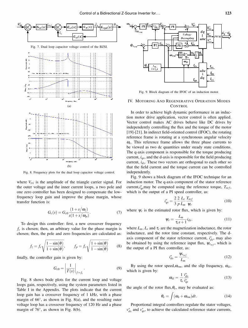
In order to achieve high dynamic performance in an induc-tion motor drive application, vector control is often applied.Vector control makes AC drives behave like DC drives byindependently controlling the flux and the torque of the motor[19]-[21]. In indirect field-oriented control (IFOC), the rotatingreference frame is rotating at a synchronous angular velocityωe. This reference frame allows the three phase currents tobe viewed as two dc quantities under steady state conditions.The q-axis component is responsible for the torque producingcurrent, iqs, and the d-axis is responsible for the field producingcurrent, ids. These two vectors are orthogonal to each other sothat the field current and the torque current can be controlledindependently.
Fig. 9 shows a block diagram of the IFOC technique for aninduction motor. The q-axis component of the stator referencecurrent,i∗qsmay be computed using the reference torque, Tre f ,which is the output of a PI speed controller, as:
i∗qs =23
2p
Lr
Lm
Tre f
ψr(10)
where ψr is the estimated rotor flux, which is given by:
ψr =Lm
τrs+1ids. (11)
where Lm, Lr and τr are the magnetization inductance, the rotorinductance, and the rotor time constant, respectively. The d-axis component of the stator reference current, i∗ds, may alsobe obtained by using the reference input flux, ψrre f , which isthe output of a PI flux controller, as:
i∗ds =ψrre f
Lm. (12)
By using the rotor speed,ωrm, and the slip frequency, ωsl ,which is given by:
ωsl =1τr
i∗dsi∗qs
(13)
the angle of the rotor flux,θe, may be evaluated as:
θe =∫(ωe +ωrm)dt. (14)
Proportional integral controllers regulate the stator voltages,v∗ds and v∗qs, to achieve the calculated reference stator currents,

124 Journal of Power Electronics, Vol. 11, No. 2, March 2011
(a)
(b)
Fig. 10. Flux and speed regulation block diagrams.
TABLE IIPI CONTROLLERS PARAMETERS EQUATIONS
Speed controllerkps = 2Jξ ωn−Fkis = Jω2
n (2ξ 2−1)
Flux controllerkp f = (2τrξ ωn−1)
/Lm
ki f = τrω2n (2ξ 2−1)
/Lm
Current controllerkpi = 2R1T1ξ ωn−R1kii = R1T1ω2
n (2ξ 2−1)
i∗ds and i∗qs. The required voltage is then synthesized by theinverter using pulse width modulation (PWM). During motoroperation the actual rotor resistance and inductance can vary.The resulting errors between the values used and the actualparameters cause an incomplete decoupling between the torqueand the flux. In order to compensate for this incomplete de-coupling, the values of compensation voltages are added to theoutput of the current controllers. This voltage compensationcan improve the performance of the current control loops. Thecompensations terms are given by [20]:
vdsc =−ωeσLsi∗qsvdsc = ωeσLsi∗ds +
LmLr
ωrψr. (15)
The parameters of four PI controllers are calculated basedon the block diagram shown in Fig. 10 [21]. They are notoptimized using practical swarm optimization (PSO) as in [22]or tuned by trial and error. Table II shows the derived equationsused to calculate these parameters, where ξ , ωnare the desireddamping and dynamics response specifications, while R1 =Rs +Rr · L2
m/
L2r is the combined motor resistance, and T1 =
σLs/
R1 is the current model time constant.Fig. 11 shows the entire closed loop system containing:
the input battery, the BZSI, the capacitor voltage control andthe IFOC speed control, where the capacitor voltage controlgenerates the shoot-through duty ratio and the IFOC generatesthe modulation index according to the operating conditions.
V. GRID CHARGING/DISCHARGING OPERATION MODECONTROL
The main goals of the grid interface control technique are toensure the required power in a three phase grid during batterydischarge and to provide enough charge power during batterycharging. By regulating the capacitor voltage and hence thedc-link voltage at a certain level, the Z-source inverter can beconveniently regulated by a current control method. Thus, aneffective algorithm for the AC current control is needed. Thecontroller for the AC side of the inverter was designed in thestationary reference frame using a proportional plus resonance
controller (PR), its transfer function is [23]:
Gc(s) = Kp +2Kis
s2 +ω20
(16)
where Kp, Ki andω0 are the proportional gain, the integral gainand the angular frequency at the fundamental frequency. Theresonance controller gives an infinite gain at the fundamentalfrequency which results in integral action at that particularfrequency while removing the steady state error. Fig. 12, showsthe control strategy of a grid connected bidirectional ZSI.Where P* is the required power injected into or drawn fromthe grid. Using this power and the measured grid voltagecomponents in the stationary reference frame, vd , vq, thereference currents are calculated by [24]:
i∗d =vd
v2d + v2
q·P∗, i∗q =
vq
v2d + v2
q·P∗. (17)
The phase angle θ of the grid voltage is detected by a PLLand is used in the abc-dq and dq-abc transformations. TwoPR controllers are used to control the d-q axis output currentcomponents. The output of these controllers is transformedfrom dq to abc to generate the modulation signals, as shownin Fig. 12.
VI. SIMULATION RESULTS
In order to verify the proposed control strategies duringdifferent operation modes, two simulation models were carriedout using MATLAB/SIMULINK software, with the parameterslisted in Table I in the Appendix. The first model is usedto verify the proposed speed control strategy during themotoring and regenerative braking operation modes of a 15kW induction motor fed by a BZSI. The second model is usedto verify the proposed control strategy of a grid connectedBZSI during the charging/discharging operation mode with anactive power of up to 15 kW. In both models the simple boostshoot-through control method is used.
Figs. 13-16 show the BZSI fed induction motor responseduring the motoring and regenerative braking operation modes.The system is operated in different operation modes, as shownin Fig. 13: the acceleration mode with the rated torque duringthe time interval 0-0.2 sec, the steady state operation modewith the rated torque and the rated speed during the timeinterval 0.2-0.6 sec, the overloaded transient mode with 120%of the rated torque and the rated speed during the time interval0.6-1 sec, the deceleration transient mode from the ratedspeed to half of the rated speed with the rated torque duringtime interval 1-1.2 sec, the light load transient mode withhalf the rated load and half the rated speed during the timeinterval 1.2-1.6 sec, the regenerative braking mode duringthe time interval 1.6-1.8 sec and the standstill mode duringthe time interval 1.8-1.9 sec. Fig. 14 shows reference andthe actual Z-network capacitor voltages, where the capacitorvoltage is controlled to be 653 V, and the dc link voltagechanges, the shoot-through duty ratio which is generated fromthe capacitor voltage control, the modulating signal which isgenerated from the IFOC control as well as the referenceand actual Z-network inductor currents. Fig. 15 shows thebattery voltage, the current and the SOC as well as their

Control of a Bidirectional Z-Source Inverter for. . . 125
Fig. 11. Closed loop speed control of three phase induction motor fed by a BZSI during motoring and regenerative operation modes.
Fig. 12. Control strategy for the grid connected BZSI during charging/discharging mod.
variations during the above mentioned operation modes. Fig.16 shows the battery power and the motor’s electric andmechanical powers for the same operation modes. Figs. 17-19 show the grid connected BZSI during charging/dischargingoperation mode. The simulation model is tested for one secin two different operation modes: the battery charging fromthe grid during the time interval 0-0.5 sec and the batterydischarging to the grid during the time interval 0.5-1 sec. Fig.17 shows the battery SOC, current and voltage, where the SOCincreases during battery charging (negative battery current) anddecreases during battery discharging (positive battery current).Fig. 18 shows the Z-network capacitor voltage and the inductorcurrent during the battery charging/discharging mode. Fig.19 shows the grid voltage and current during the transitionbetween the charging/discharging operation modes at t=0.5sec.
VII. EXPERIMENTAL RESULTS
In order to verify the simulation results, a prototype of a30 kW ZSI is designed and implemented using the parametersin Table III in the Appendix, as shown in Fig. 20, to drive a19 kW induction motor. For the realization of the proposedcontrol methods an evaluation board eZdspTM F2808 basedon a TMS320F2808 Digital Signal Processor (DSP) has beenchosen [25]. The eZdsp evaluation board is connected to aPC using a USB cable and the PC has MATLAB, Real Timeworkshop (RTW) and code composer studio (CCS) installedon it for automatic code generation and real time control.Figs. 21-27 show the experimental results. Fig. 21 shows theswitching signal for phase A of the ZSI, where the shoot-through state is indicated. Figs. 22 and 23 show the inductionmotor line voltages and the phase currents when the motordraws 10 A (25% rated load) and 25 A (65% rated load)from the ZSI, respectively. Figs. 24 and 25 show, the input

126 Journal of Power Electronics, Vol. 11, No. 2, March 2011
Fig. 13. Motor response during motoring and regenerative braking operation modes.
Fig. 14. BZSI response during motoring and regenerative braking operation modes.
voltage, the capacitor voltage, the dc-link voltage and theinductor current of the ZSI at 25% and 65% of the rated load,respectively. As shown in Figs. 24-25, the capacitor voltage iscontrolled to be 300 V even when the motor load changes from25% to 65% of the rated load. Fig. 26 shows the input voltage,the capacitor voltage, the dc-link voltage and the inductorof the ZSI in the switching frequency at 65% of the ratedload. Fig. 27 shows the steady state speed and torque of theinduction motor at 65% of the rated load.
VIII. CONCLUSION
This paper proposes two control strategies for bidirectionalZ-source inverters for electric vehicle applications. The firstcontrol strategy utilizes the indirect field-oriented control(IFOC) method to control the induction motor speed duringmotoring and regenerative braking operation modes. The sec-
ond control strategy utilizes a proportional plus resonance (PR)controller to control the AC current for connecting a BZSI tothe grid during battery charging/discharging operation mode.In both control strategies the Z-network capacitor voltage iscontrolled by a dual loop control. The first control strategy istested during standard (acceleration, steady state, regenerativebraking and standstill) and transient (overload, decelerationand light load) modes. The second control strategy is testedduring battery charging/discharging operation mode. MAT-LAB simulations and experimental results verify the validityof the proposed control strategies during different operationmodes. The application of a BZSI to battery operated electricvehicles (BEV) can improve their efficiency and reduce theirproduction cost due to a lower component count, since it is aone stage converter with a reduced volume and easier controlimplementation.

Control of a Bidirectional Z-Source Inverter for. . . 127
(a)
(b)
Fig. 15. Battery voltage and current (a), battery state of charge (SOC) during motoring and regenerative braking operation modes.
Fig. 16. Battery power and motor electric and mechanical powers during motoring and regenerative braking operation modes.

128 Journal of Power Electronics, Vol. 11, No. 2, March 2011
Fig. 17. Battery state of charge (SOC), voltage and current and during grid charging/discharging operation mode.
Fig. 18. Z-network capacitor voltage and inductor current and during grid charging/discharging operation mode.
Fig. 19. Grid voltage and current during transition between charging/discharging operation modes.

Control of a Bidirectional Z-Source Inverter for. . . 129
Fig. 20. Experimental setup of a 30 kW ZSI.
Fig. 21. Switching signal of phase A of the BZSI.
Fig. 22. Motor line voltages and phase currents 25% of the rated load.
Fig. 23. Motor line voltages and phase currents 65% of the rated load.
Fig. 24. BZSI waveforms in line frequency at 25% rated load.
Fig. 25. BZSI waveforms in line frequency at 65% rated load.
Fig. 26. BZSI waveforms in switching frequency at 65% rated load.
Fig. 27. steady state speed and torque at 65% rated load.

130 Journal of Power Electronics, Vol. 11, No. 2, March 2011
APPENDIX
TABLE ISIMULATION SYSTEM PARAMETERS
Parameter ValueBIDIRECTIONAL ZSI PARAMETERSInductance 500 µHCapacitance 500 µFSwitching frequency 10 kHzBATTERY PACKAGE PARAMETERSRated capacity 11 AhNominal voltage 490 VInternal resistance 1.11 Ω
INDUCTION MOTOR PARAMETERSOutput power 15 kWRMS line voltage 400 VInput frequency 50 HzNo. of poles 4Stator resistance, Rs 0.2205 Ω
Rotor resistance, Rr 0.2147 Ω
Stator inductance, Lls 0.991 mHRotor inductance, Llr 0.991 mHMutual inductance, Lm 64.19 mHInertia, J 0.102 kg. m2Fraction factor, J 0.009541 N.m.sGRID PARAMETERSNominal grid line voltage 380 VGrid inductance 5 mH
TABLE IIIEXPERIMENTAL SYSTEM PARAMETERS
Parameter ValueZSI parametersInductance 700 µHCapacitance 320 µFSwitching frequency 10 kHzInduction Motor ParametersOutput power 19 kWRMS line voltage 380 VInput frequency 50 HzNo. of poles 4Stator resistance, Rs 0.16 Ω
Rotor resistance, Rr 0.21 Ω
Stator inductance, Lls 0.05 HRotor inductance, Llr 0.12 HMutual inductance, Lm 0.076 H
REFERENCES
[1] M. Shen and F. Z. Peng, “Converter systems for hybrid electric vehicles,”International Conference on Electrical Machines and Systems, pp. 2004-2010, 2007.
[2] F. Z. Peng, “Z-Source inverter,” IEEE Trans. Ind. Appl., pp. 504-510,Vol. 39, No. 2, Mar./Apr. 2003.
[3] F. Z. Peng, X. Yuvan, X. Fang, and Z. Qian, “Z-source inverter for motordrives,” IEEE Trans. Power Eletron., Vol. 20, No. 4, pp.857-863, Jul.2005.
[4] S. Thangaprakashy and A. Krishnan, “Current mode integrated controltechnique for Z-source inverter fed induction motor drives,” Journal ofPower Electronics, Vol.10, No.3, pp.285-292, May 2010.
[5] X. Haiping, F. Z. Peng, L. Chen, and X. Wen, “Analysis and design ofBi-directional Z-source inverter for electrical vehicles,” in Proc. APEC,pp.1252-1257, 2008.
[6] M. Shen and F. Z. Peng, “Operation modes and characteristics of the Z-source inverter with small inductance or low power factor,” IEEE Trans.Ind. Eletron., Vol. 55, No. 1, pp. 89-96, Jan. 2008.
[7] X. Ding, Z. Qian, S. Yang and F. Z. Peng, “A new feedforwardcompensation to reject DC-link voltage ripple in bi-directional Z-sourceinverter ASD system,” in Proc. APEC, pp. 1809-1813, 2008.
[8] M. Yamanaka and H. Koizum, “A bi-directional Z-source inverter forelectric vehicles,” International Conference on Power Electronics andDrive Systems, pp.574-578, 2009.
[9] S. M. Dehghan, M. Mohamadian, and A. Yazdian, “Hybrid electricvehicle based on bidirectional Z-source nine-switch inverter,” IEEETrans. Vehicular Technology, Vol. 59, No. 6, PP.2641-2653, Jul. 2010.
[10] X. Ding, Z. Qian, S. Yang, B. Cuil, and F. Z. Peng, “A new adjustable-Speed Drives (ASD) system based on high-performance Z-source in-verter,” in Proc. IAS, pp.2327-2332, 2007.
[11] S. Chakraborty, B. Kramera, and B. Kroposkia, “A review of powerelectronics interfaces for distributed energy systems towards achievinglow-cost modular design,” Renewable and Sustainable Energy Reviews,Vol. 13, No. 9, pp. 2323-2335, Jun. 2009.
[12] X. Ding, Z. Qian, S. Yang, B. Cui, and F. Peng, “A PID Control Strategyfor DC-link Boost Voltage in Z-source Inverter,” in Proc. APEC, pp.1145-1148, 2007.
[13] Q.-V. Tran, T.-W. Chun, H.-G. Kim, and E.-C. Nho, “Minimizationof voltage stress across switching devices in the Z-source inverter bycapacitor voltage control,” Journal of Power Electronics, Vol. 9, No.3,pp.335-342, May 2009.
[14] X. Ding, Z. Qian, S. Yang, B. Cui, and F. Z. Peng, “A direct DC-linkboost voltage PID-like fuzzy control strategy in Z-source inverter,” inProc. PESC, pp. 405-411, 2008.
[15] X. Ding, Z. Qian, S. Yang, B. Cui, and F. Peng, “A direct peak DC-linkboost voltage control strategy in Z-source inverter,” in Proc. APEC, pp.648-653, 2007.
[16] Y. Tang, J. Wei, and S. Xie, “A new direct peak DC-link voltage controlstrategy of Z-source inverters,” in Proc. APEC, pp. 867–872, 2010.
[17] M. Zeraoulia, M. E. H. Benbouzid, and D. Diallo, “Electric motor driveselection issues for HEV propulsion systems: a comparative study,” IEEETrans. Vehicular Technology, Vol. 55, No. 6, pp.1756-1764, Nov. 2006.
[18] Jingbo Liu, Jiangang Hu, and Longya Xu, “Dynamic modeling andanalysis of z source converter-derivation of AC small signal model anddesign-oriented analysis,” IEEE Trans. Power Electron., Vol. 22, No. 5,pp. 1786-1796, Sep. 2007.
[19] M. A. Mannan, T. Murata, J. Tamura, and T. Tsuchiya, “Indirect fieldoriented control for high performance induction motor drives using spacevector modulation with consideration of core loss,” in Proc. PESC, Vol.3, pp. 1449-1454, 2003.
[20] I. K. Bousserhane, A. Hazzab, M. Rahli, M. Kamli, and B. Mazari,“Direct field-oriented control using backstepping strategy with fuzzy ro-tor resistance estimator for induction motor speed control,” InformationTechnology and Control, Vol. 4, No. 4, pp. 403– 411, 2006.
[21] A. Mansouri, M. Chenafa, A. Bouhenna, and E. Etien, “Powerfulnonlinear observer associated with field-oriented control of an inductionmotor,” Int. J. Appl. Math. Comput. Sci., Vol. 14, No. 2, 209–220, Jun.2004.
[22] E. A. Saber, “A novel technique for tuning PI-controllers in inductionmotor drive systems for electric vehicle applications,” Journal of PowerElectronics, Vol. 6, No.4, pp.322-329, Oct. 2006.
[23] S. Zhang, K.-J. Tseng, D. M. Vilathgamuwa, T. D. Nguyen, and X.-Y.Wang, “Design of a robust grid interface system for PMSG-based windturbine generators,” IEEE Trans. Ind. Electron., Vol. 58, No. 1, pp. 316-328, Jan. 2011.
[24] J.-H. Park, H.-G. Kim, E.-C. Nho, and T.-W. Chun, “Power conditioningsystem for a grid connected PV power generation using a quasi-z-sourceinverter,” Journal of Power Electronics, Vol. 10, No. 1, pp.79-84, Jan.2010.
[25] Texas Instruments, Inc., “eZdspTM F2808 USB,” Technical Reference2005.
Omar Ellabban was born in Egypt in 1975. He receivedhis B.S. from Helwan University, CityHelwan, Egypt in1998 and his M.S. from Cairo University, Giza, Egypt in2005, both in Electric Power and Machines Engineering.He is currently pursuing his Ph.D. in Electrical Engi-neering at Vrije Universiteit Brussel, Brussels, Belgium.His research interests include motor drives, artificialintelligence, converter design, hybrid electric vehiclecontrol and DSP-based system control.

Control of a Bidirectional Z-Source Inverter for. . . 131
Joeri Van Mierlo obtained his Ph.D. in Electrome-chanical Engineering Sciences from Vrije UniversiteitBrussel in 2000. He is now a Full Time Professorat this university, where he leads the MOBI - Mo-bility and Automotive Technology Research Group.His current research interests include the developmentof hybrid propulsion systems (converters, supercaps,energy-management, etc.) as well as the environmentalcomparison of vehicles with different kinds of drive
trains and fuels (LCA, WTW). He is the author of more than 100 scientificpublications. He chairs the EPE chapter on “Hybrid and Electric Vehicles”(www.epe-association.org). He is the Secretary of the Board of the Belgiansection of AVERE (ASBE) and is a Board Member of AVERE. He is a Co-Editor of the Journal of Asian Electric Vehicles. He is an active Member ofEARPA - the Association of Automotive R&D Organizations. Furthermore he
is a Member of Flanders Drive and of VSWB – the Flemish Cooperative onHydrogen and Fuels Cells. Prof. Van Mierlo is Chairman of the InternationalProgram Committee of the International Electric, Hybrid and Fuel CellSymposium (EVS24).
Philippe Lataire received a degree in Electromechan-ical Engineering in 1975 and his Ph.D. in 1982, bothfrom Vrije Universiteit Brussel (VUB), Brussels, Bel-gium. He is presently a Full Time Professor at VUB. Hiscurrent research interests include electric drives, powerelectronics and control.