control box for unloader stec-360a - … stec... · control box for unloader stec-360a ... this...
TRANSCRIPT

Control Box for Unloader
STEC-360A Operation Manual <NC Program Edition>
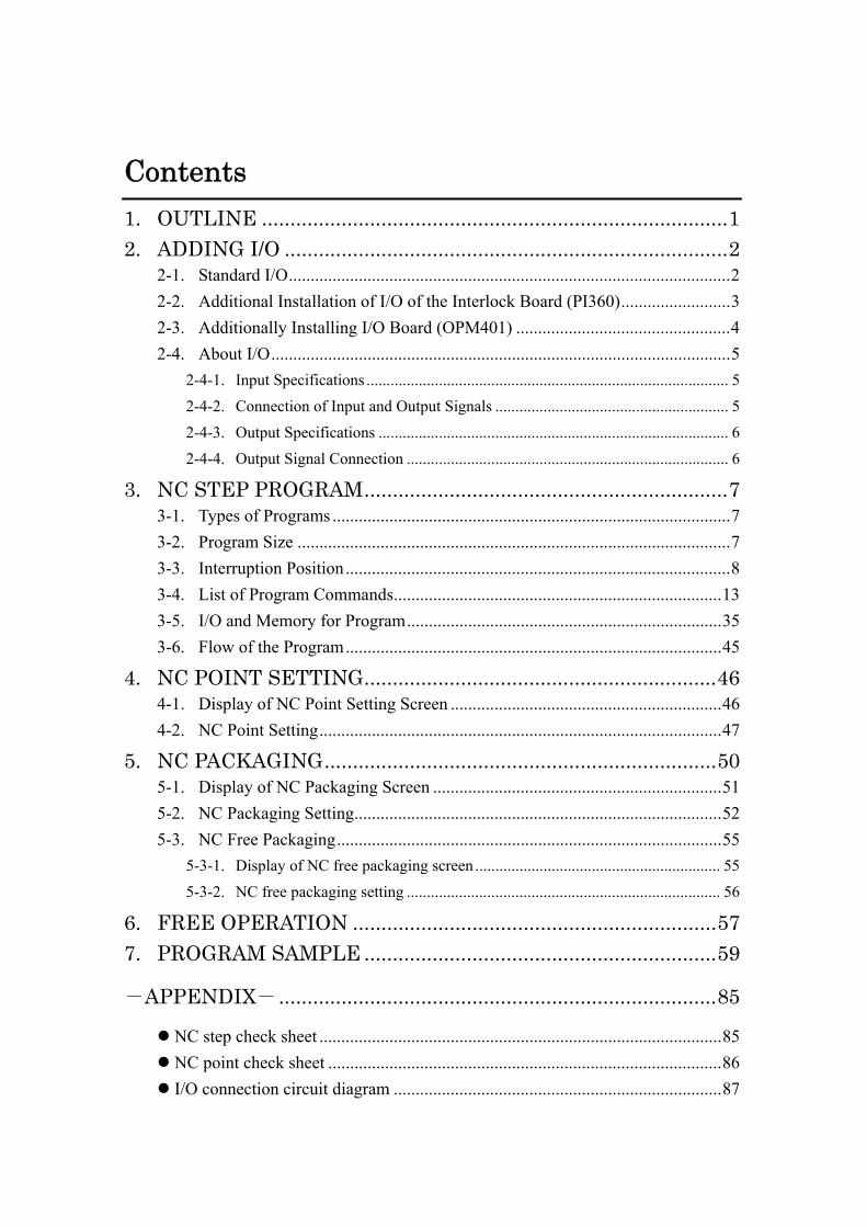
Contents 1. OUTLINE ..................................................................................1 2. ADDING I/O ..............................................................................2
2-1. Standard I/O.....................................................................................................2 2-2. Additional Installation of I/O of the Interlock Board (PI360).........................3 2-3. Additionally Installing I/O Board (OPM401) .................................................4 2-4. About I/O.........................................................................................................5
2-4-1. Input Specifications .......................................................................................... 5 2-4-2. Connection of Input and Output Signals .......................................................... 5 2-4-3. Output Specifications ....................................................................................... 6 2-4-4. Output Signal Connection ................................................................................ 6
3. NC STEP PROGRAM................................................................7 3-1. Types of Programs ...........................................................................................7 3-2. Program Size ...................................................................................................7 3-3. Interruption Position........................................................................................8 3-4. List of Program Commands...........................................................................13 3-5. I/O and Memory for Program........................................................................35 3-6. Flow of the Program......................................................................................45
4. NC POINT SETTING..............................................................46 4-1. Display of NC Point Setting Screen ..............................................................46 4-2. NC Point Setting............................................................................................47
5. NC PACKAGING.....................................................................50 5-1. Display of NC Packaging Screen ..................................................................51 5-2. NC Packaging Setting....................................................................................52 5-3. NC Free Packaging........................................................................................55
5-3-1. Display of NC free packaging screen ............................................................. 55 5-3-2. NC free packaging setting .............................................................................. 56
6. FREE OPERATION ................................................................57 7. PROGRAM SAMPLE ..............................................................59
-APPENDIX- .............................................................................85
NC step check sheet ............................................................................................85 NC point check sheet ..........................................................................................86 I/O connection circuit diagram ...........................................................................87

- 1 -
1. OUTLINE STEC-360A is equipped with the interrupt program function that can insert any given NC program between basic operations. (Option) It is necessary to turn ON “Interrupt NC program” mode by the system mode to use this function. The interrupt program will not be executed even if the program is input while the mode is turned OFF. You can use the function by adding the I/O board or I/O interface board when newly connecting the input and output equipment and creating the program. Four types of programs are provided according the uses. This manual provides various information regarding the above mentioned additional board and interrupt program. Please refer to separate Operation Manual <Operation Edition> as for basic programming and operation of STEC-360A.

- 2 -
2. ADDING I/O
2-1. Standard I/O It is not necessary to additionally install I/O when you do not use new input and output signals or you create a program within the range of the following input and output signals even if you use the interrupt program. The input and output signal at the machine side is controlled by the carriage unit relay board. The standard input and output signals are as follows. As for input and output which are optionally reserved, you can use them when options are not installed or not to be installed. * Please note that these input and output are used when options are installed.
Signal name Details OTB
470Signal name Details OTB
470 L1 Traverse axis home position V1U L2 Traverse axis overrun V1D L12 Traverse axis release side area V1DH L3 Product arm ascent end V1S L3S (S) arm ascent end V2B L4 Product confirmation V2A L4T Product confirmation in the chuck V2S L4V Suction confirmation V31 Chuck open L4S Runner confirmation V3V Suction release L5 V32 Spool chuck open L6 V3S Runner chuck open L7 V4R Posture return L8 Posture return end V4P Posture action L9 Posture action end V5 Hook removal L10 Traverse axis extract side area V6 Nipper in the chuck L11 Hook removal end V7 Rotation return PS Air pressure V8 Rotation action L13 Spare input 2 V9 NT pull L14 Rotation return end V10 NT cut L15 Rotation action end V11 NT position L16 Suction confirmation 2 V12 NT unit advance L17 Spare input 1 V13 Suction release 2 L33 Interference prevention V14 Chuck slide THT Traverse axis thermal V15 Air blow LHW Product crosswise axis home position V16 Spare output 1 LOW Product crosswise axis overrun V17 Suction *1 LHS (S) Crosswise axis home position V18 Suction 2 LOS (S) Crosswise axis overrun MTB Traverse axis brake LHV Product vertical axis home position MBW Product crosswise axis brake LOV Product vertical axis overrun MBS (S) Crosswise axis brake LHVS (S) Vertical axis home position MBV Product vertical axis brake LOVS (S) Vertical axis overrun MBVS (S) Vertical axis brake
* Check input and output before using the unit because spare input and output may be used
according to the optional specifications of the unit. *1 V17 is used at suction (standard).
Opt
iona
lly r
eser
ved
inpu
t
Opt
iona
lly r
eser
ved
inpu
t O
ptio
nally
res
erve
d in
put

- 3 -
2-2. Additional Installation of I/O of the Interlock Board (PI360) Additionally installing I/O interface board (SIOF88) on the interlock board (PI360) allows use of sixteen input and output points. Names of additional installation positions and signals are as follows; * Be careful because these input and output are used when an option is attached.
Additional installation positions (connected to CON B, CON C)
Details of signals
INPUT OUTPUT MD Safety door close RY1 Mold open safety MO Mold open complete RY2 Mold close safety MC Mold close complete RY3 Cycle start ME Ejector end RY4 MN Defective product signal RY5 Alarm RD Release side descend command RY6 Jig start OD Release side safety RY7 Ejector advance SP7 RY8 MA Molding machine automatic SP10 H100 Mold replacement request 9B H130 Mold replacement allowed 5B H109 Mold No. set 9A H131 Setting error 5A H110 Setting start 8B H132 Setting complete 4B H111 Unloader operation allowed 8A H133 Setting operating 4A H112 Error reset 7B 3B 7A 3A 6B 2B 6A 2A H101 Mold No. 27 9B H134 Mold No. answer 27 5B H102 Mold No. 26 9A H135 Mold No. answer 26 5A H103 Mold No. 25 8B H136 Mold No. answer 25 4B H104 Mold No. 24 8A H137 Mold No. answer 24 4A H105 Mold No. 23 7B H138 Mold No. answer 23 3B H106 Mold No. 22 7A H139 Mold No. answer 22 3A H107 Mold No. 21 6B H140 Mold No. answer 21 2B H108 Mold No. 20 6A H141 Mold No. answer 20 2A
* Check the specifications of the unit in advance because input and output 1 to 6 may be used according to the optional specifications of the unit.
Optionally reserved input output SIOF88 CON B
Optionally reserved input output SIOF88 CON C

- 4 -
2-3. Additionally Installing I/O Board (OPM401) Input and output can be used by additionally installing I/O interface as follows: * Install the external power supply for input and output when additionally installing this I/O
board (OPM401). 1) Additionally installing OPM401 ・・・・・・・・・・・・・・・・・・・・・・・I/O : 8/8 2) Additionally installing OPM401and one SIOF88 ・・・・・・・・・I/O : 8/8 + 8/8
3) Additionally installing OPM401 and two SIOF88・・・・・・・・・・I/O : 8/8 + 8/8 × 2 4) Additionally installing OPM401 and three SIOF88・・・・・・・・・I/O : 8/8 + 8/8 × 3
INPUT OUTPUT I 10 Input 10 9B O 10 Output 10 5B I 11 Input 11 9A O 11 Output 11 5A I 12 Input 12 8B O 12 Output 12 4B I 13 Input 13 8A O 13 Output 13 4A I 14 Input 14 7B O 14 Output 14 3B I 15 Input 15 7A O 15 Output 15 3A I 16 Input 16 6B O 16 Output 16 2B I 17 Input 17 6A O 17 Output 17 2A I 18 Input 18 9B O 18 Output 18 5B I 19 Input 19 9A O 19 Output 19 5A I 20 Input 20 8B O 20 Output 20 4B I 21 Input 21 8A O 21 Output 21 4A I 22 Input 22 7B O 22 Output 22 3B I 23 Input 23 7A O 23 Output 23 3A I 24 Input 24 6B O 24 Output 24 2B I 25 Input 25 6A O 25 Output 25 2A I 26 Input 26 9B O 26 Output 26 5B I 27 Input 27 9A O 27 Output 27 5A I 28 Input 28 8B O 28 Output 28 4B I 29 Input 29 8A O 29 Output 29 4A I 30 Input 30 7B O 30 Output 30 3B I 31 Input 31 7A O 31 Output 31 3A I 32 Input 32 6B O 32 Output 32 2B I 33 Input 33 6A O 33 Output 33 2A I 34 Input 34 9B O 34 Output 34 5B I 35 Input 35 9A O 35 Output 35 5A I 36 Input 36 8B O 36 Output 36 4B I 37 Input 37 8A O 37 Output 37 4A I 38 Input 38 7B O 38 Output 38 3B I 39 Input 39 7A O 39 Output 39 3A I 40 Input 40 6B O 40 Output 40 2B I 41 Input 41 6A O 41 Output 41 2A
OPM401 CON D
SIOF88 CON C
SIOF88 CON B
SIOF88 CON A

- 5 -
2-4. About I/O
2-4-1. Input Specifications Input type DC input (sink type) Input voltage Internal power source (DC24V) or external power source (DC24V ±15%) Input current 10 mA or less Operating voltage ON voltage: 2V or less
OFF voltage: 18V or more Insulation method Photo coupler insulation
2-4-2. Connection of Input and Output Signals
Carriage unit relay board (OTB470)
I/O interface board (SIOF88), additional I/O board (OPM401)
*Conditions for external contact and the like ・・・・・・・・・・・・・・・・・・・・・・・・・・・・・・ Contact capacity: DC30V/20mA or more Leak current between contacts when it is OFF (when opening circuit): 100 µA or less

- 6 -
2-4-3. Output Specifications Output type Transistor output (sink type) Rated load voltage DC24V Maximum load current
100mA/point (OTB470) 500mA or less (OPM401, SI0F88)
Leak current 0.1mA or less
2-4-4. Output Signal Connection
Carriage unit relay board (OTB470)
I/O interface board (SIOF88) and additional I/O board (OPM401)
* Take measures against noise by placing the diode and the like as close as possible to the
load when the load is the inductive one (relay coil, solenoid, and the like).

- 7 -
3. NC STEP PROGRAM
3-1. Types of Programs The programs are used to be pre-installed in the in the standard operating program for interruption. 255 programs can be used totally as the interruption program functions. Numbers 1 to 255 are allocated to all the programs. Details of the numbered programs are as follows; Program number Use
1 to 50 For interruption to the product side arm operation 51 to 100 For interruption to the runner side arm operation
* 81 to 100 are for runner side arm individual operation 101 to 240 For serial start (instructed by the program for interruption)
This is used when operating in parallel with the standard operation of the unloader or when the secondary processing machine individually operates.
* 201 to 216 can be started by NC free button. 241 to 250 For home position return
* This is instructed by the standard operation program. 251 to 255 For monitoring of alarm and the like (instructed by the interruption program)
It monitors LS input and the like as necessary and can stop all the interruption programs being executed (except for No. 251 to 255) by the command of PAUSE ON.
3-2. Program Size Program capacity 32k Approximately 470 lines Number of points that can be described in a program
100 points per axis
Packaging 2 types PLT1: Standard packaging (255 × 255 × 255) PLT2: Free packaging (55 points) * You need to confirm the range to be used in advance because it
used may be limited according to the optional specifications. Number of points for free packaging: Up to 255 points including the number of points used by the standard operation program
- 8 -
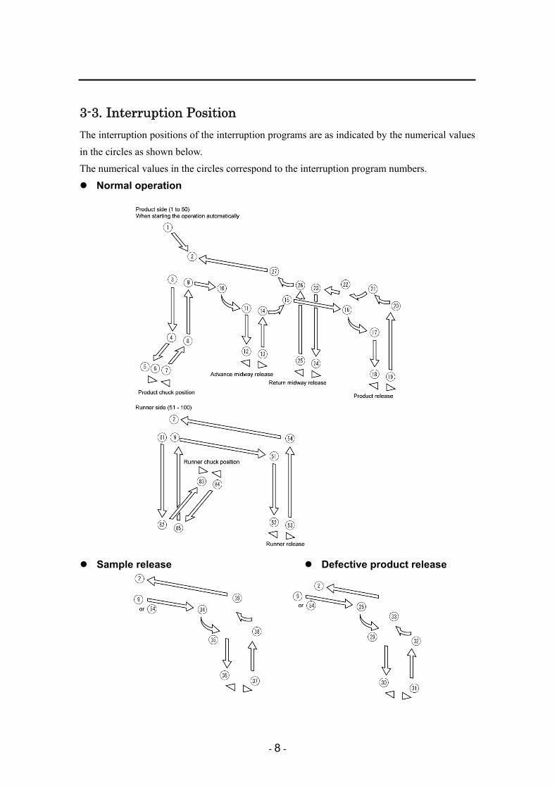
3-3. Interruption Position The interruption positions of the interruption programs are as indicated by the numerical values in the circles as shown below. The numerical values in the circles correspond to the interruption program numbers.
Normal operation
Sample release Defective product release

- 9 -
Conditions before starting the standard interruption program Conditions before and after machine side operation at each interruption position are as shown below;
Interruption position number
Condition before interruption
Condition after interruption
◯1 Automatic Home position return operation
◯2 Movement of the unloader stand-by position complete
Mold open complete (MO) Waiting for ON
◯3 MDW ON Mold open complete (MO) ON
Produce side arm unloader descend Descend timer (T1) start
◯4 MDW ON Product side arm unloader descend (path) complete Descend timer (T1) UP
Produce side arm unloader advance Advance timer (T2) start
◯5 MDW ON Product side arm unloader advance complete Advance timer (T2) UP
Ejector end memory (MEE) Waiting for ON
◯6 MDW ON Ejector end memory (MEE) ON
Chuck close Chuck close timer (T4) start
◯7 MDW ON Chuck close timer (T4) UP
Product side arm unloader return Return timer (T5) start
◯8 MDW ON Product side arm unloader return (path) complete Return timer (T5) UP
Product side arm unloader ascent
◯9 Ascent end (L3 • L3S) ON MDS ON Runner release position movement → ◯51 * Note 2
MDS OFF • MDTF ON Advance midway release position movement → ◯10
MDS OFF • MDTF OFF Product release position movement → ◯16 * Note 1
◯10 MDW ON • MDTF ON Advance midway release position movement complete
Posture action Posture action timer (T7) start
◯11 MDW ON • MDTF ON Posture action end (L9) ON Posture action timer (T7) UP
Midway release position descend Midway release timer (T12) start
◯12 MDW ON • MDTF ON Midway release position descend complete Midway release timer (T12) UP
Sprue chuck open Sprue chuck open timer (T13) start
◯13 MDW ON • MDTF ON Sprue chuck open timer (T13) UP
Release side ascent position movement
- 10 -
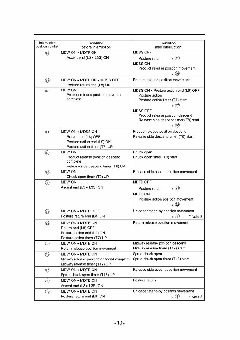
Interruption position number
Condition before interruption
Condition after interruption
◯14 MDW ON • MDTF ON Ascent end (L3 • L3S) ON
MDSS OFF
Posture return → ◯15 MDSS ON
Product release position movement → ◯16
◯15 MDW ON • MDTF ON • MDSS OFF Posture return end (L8) ON
Product release position movement
◯16 MDW ON Product release position movement complete
MDSS ON・Posture action end (L9) OFF Posture action Posture action timer (T7) start → ◯17
MDSS OFF Product release position descend Release side descend timer (T8) start → ◯18
◯17 MDW ON • MDSS ON Return end (L8) OFF Posture action end (L9) ON Posture action timer (T7) UP
Product release position descend Release side descend timer (T8) start
◯18 MDW ON Product release position descend complete Release side descend timer (T8) UP
Chuck open Chuck open timer (T9) start
◯19 MDW ON Chuck open timer (T9) UP
Release side ascent position movement
◯20 MDW ON Ascent end (L3 • L3S) ON
MDTB OFF
Posture return → ◯21 MDTB ON
Posture action position movement → ◯22
◯21 MDW ON • MDTB OFF Posture return end (L8) ON
Unloader stand-by position movement → ◯2 * Note 2
◯22 MDW ON • MDTB ON Return end (L8) OFF Posture action end (L9) ON Posture action timer (T7) UP
Return release position movement
◯23 MDW ON • MDTB ON Return release position movement
Midway release position descend Midway release timer (T12) start
◯24 MDW ON • MDTB ON Midway release position descend completeMidway release timer (T12) UP
Sprue chuck open Sprue chuck open timer (T13) start
◯25 MDW ON • MDTB ON Sprue chuck open timer (T13) UP
Release side ascent position movement
◯26 MDW ON • MDTB ON Ascent end (L3 • L3S) ON
Posture return
◯27 MDW ON • MDTB ON Posture return end (L8) ON
Unloader stand-by position movement → ◯2 * Note 2
- 11 -
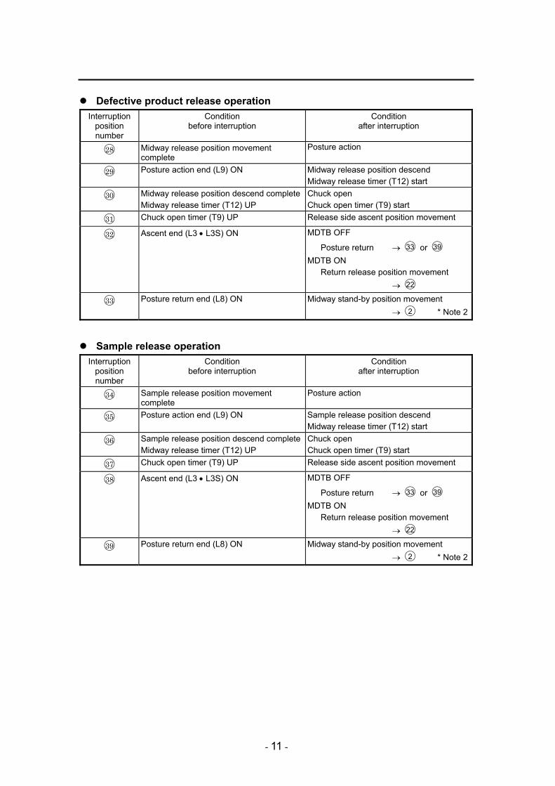
Defective product release operation Interruption
position number
Condition before interruption
Condition after interruption
◯28 Midway release position movement complete
Posture action
◯29 Posture action end (L9) ON Midway release position descend Midway release timer (T12) start
◯30 Midway release position descend completeMidway release timer (T12) UP
Chuck open Chuck open timer (T9) start
◯31 Chuck open timer (T9) UP Release side ascent position movement
◯32 Ascent end (L3 • L3S) ON MDTB OFF
Posture return → ◯33 or ◯39 MDTB ON
Return release position movement → ◯22
◯33 Posture return end (L8) ON Midway stand-by position movement → ◯2 * Note 2
Sample release operation Interruption
position number
Condition before interruption
Condition after interruption
◯34 Sample release position movement complete
Posture action
◯35 Posture action end (L9) ON Sample release position descend Midway release timer (T12) start
◯36 Sample release position descend completeMidway release timer (T12) UP
Chuck open Chuck open timer (T9) start
◯37 Chuck open timer (T9) UP Release side ascent position movement
◯38 Ascent end (L3 • L3S) ON MDTB OFF
Posture return → ◯33 or ◯39 MDTB ON
Return release position movement → ◯22
◯39 Posture return end (L8) ON Midway stand-by position movement → ◯2 * Note 2

- 12 -
Runner side operation Interruption
position number
Condition before interruption
Condition after interruption
◯81 MDS ON Mold open complete (MO) ON
Runner side arm unloader descend Runner side descend timer (T37) start
◯82 MDS ON Runner side arm unloader descend (path) complete Descend timer (T37) UP
Runner side arm unloader advance Runner side advance timer (T38) start
◯83 MDS ON Runner side arm unloader advance complete Runner side advance timer (T38) UP
Runner chuck close Runner side chuck close timer (T39) start
◯84 MDS ON Runner side chuck close timer (T39) UP
Runner side arm unloader return Runner side return timer (T40) start
◯85 MDS ON Runner side arm unloader return (path) complete Runner side return timer (T40) UP
Runner side arm unloader ascent
◯51 MDS ON Runner release position movement
Runner release descend Midway release timer (T12) start
◯52 MDS ON Runner release descend complete Midway release timer (T12) UP
Sprue chuck open Sprue chuck open timer (T13) start
◯53 MDS ON Sprue chuck open timer (T13) UP
Ascent position movement
◯54 MDS ON Ascent end (L3 • L3S) ON
MDW OFF Unloader stand-by position movement → ◯2 MDW ON • MDTF OFF Product release position movement → ◯16 *Note 1MDW ON • MDTF ON Advance midway release position → ◯10
Note 1: The product release position moves to three different positions according to the state of the product. F Packaging position R Defective product release position X Sample release position
Note 2: The posture action must be conducted before moving to each position when the mode of advance unloader side posture (MDTA, MDTA2) is ON (used).

- 13 -
3-4. List of Program Commands Axis operation command
It moves the axis to the teaching position by PTP operation. [Format] MOVE Axis No. Point No. [Input example] MOVE A1 P001 ......Moves the axis No.1 to the point No.1.
1. The axes that can be input are displayed below the window when the command is input. 2. Select the axis to be moved. Then select the point and press “OK” button. * Separately sold software (PCS360) is required to edit the setting file.
POINT The program will proceed after completion of movement. Available axis No.・・・・・・・・・・・・・A1(traverse axis) to A5(S vertical axis) * Use the mark [,] when selecting multiple numbers. Available point No. ・・・・・・・・・・・・P001 to P100 Available packaging ・・・・・・・・・・・PLT1 (pitch) PLT2 (free 55 point)
MOVE

- 14 -
PTP operation will move the axis to the teaching position. [Format] MOVEP Axis No. Point No. [Input example] MOVEP A1 P001 ......Moves the axis No.1 to the point No.1.
1. The axes that can be input are displayed on the window when the command is selected. 2. Select the axis to be moved. Then select the point and press “OK” button. * Separately sold software (PCS360) is required to edit the setting file.
POINT The program will proceed without waiting for completion of movement. Available axis No.・・・・・・・・・・・・・A1(traverse axis) to A5(S vertical axis) * Use the mark [,] when selecting multiple numbers. Available point No. ・・・・・・・・・・・・P001 to P100 Available packaging ・・・・・・・・・・・PLT1 (pitch) PLT2 (free 55 point)
MOVEP

- 15 -
It conducts home return. [Format] HOME Axis No. [Input example] HOME A1................Returns the axis No.1 to the home position.
1. The axes that can be input are displayed on the window when the command is selected. 2. Press [OK] button after you select the axis which is returned to home position. * Separately sold software (PCS360) is required to edit the setting file.
POINT The program will proceed after completion of home return. Available axis No.・・・・・・・・・・・・・A1(traverse axis) to A5(S vertical axis) * Use the mark [,] when selecting multiple numbers.
HOME

- 16 -
It conducts home return. [Format] HOMEP Axis No. [Input example] HOMEP A1................Returns the axis No.1 to the home position.
1. The axes that can be input are displayed on the window when the command is selected. 2. Press [OK] button after you select the axis which is returned to home position. * Separately sold software (PCS360) is required to edit the setting file.
POINT The program will proceed without waiting for the axis to return to the home position. Available axis No.・・・・・・・・・・・・・A1(traverse axis) to A5(S vertical axis) * Use the mark [,] when selecting multiple numbers.
HOMEP

- 17 -
It stops the axis while it is moving. [Format] BREAK Axis No. [Input example] BREAK A1................Stops movement of axis No. 1.
1. The axes that can be input are displayed on the window when the command is selected. 2. Press [OK] button after you select the axis which is stopped. * Separately sold software (PCS360) is required to edit the setting file.
POINT • Available axis No.・・・・・・・・・・・・A1(traverse axis) to A5(S vertical axis) * Use the mark [,] when selecting multiple numbers. • This can be used even with MOVEP.
BREAK
- 18 -
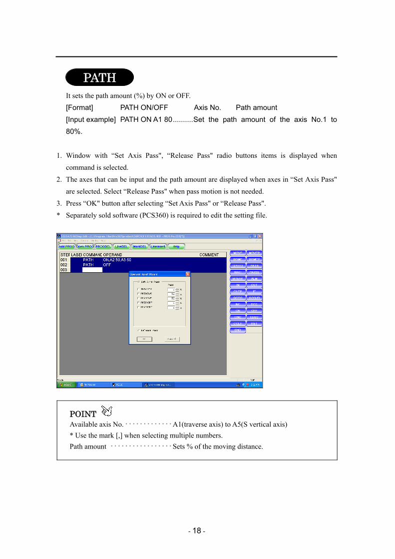
It sets the path amount (%) by ON or OFF. [Format] PATH ON/OFF Axis No. Path amount [Input example] PATH ON A1 80..........Set the path amount of the axis No.1 to 80%.
1. Window with “Set Axis Pass", “Release Pass" radio buttons items is displayed when
command is selected. 2. The axes that can be input and the path amount are displayed when axes in “Set Axis Pass"
are selected. Select “Release Pass" when pass motion is not needed. 3. Press “OK" button after selecting “Set Axis Pass" or “Release Pass". * Separately sold software (PCS360) is required to edit the setting file.
POINT Available axis No.・・・・・・・・・・・・・A1(traverse axis) to A5(S vertical axis) * Use the mark [,] when selecting multiple numbers. Path amount ・・・・・・・・・・・・・・・・・Sets % of the moving distance.
PATH

- 19 -
It sets the speed (%). [Format] SPEED Numerical value [Input example] SPEED 85 ................Set the speed of all axes to 85 %.
1. Window with “All Axis", “Set Axis" radio buttons items is displayed when command is
selected. Speed of all axes is same if “All Axis" is selected. The axes that can be input and their speed are displayed if “Set Axis" is selected.
2. Press “OK" button after selecting “All Axis " or “Set Axis ". * Separately sold software (PCS360) is required to edit the setting file.
POINT Available axis No.・・・・・・・・・・・・・A1(traverse axis) to A5(S vertical axis) * Use the mark [,] when selecting multiple numbers. Speed・・・・・・・・・・・・・・・・・・・・・・・Sets the speed by %.
SPEED

- 20 -
Input and output command
It turns ON or OFF the external output signal and internal memory. [Format] OUT signal name ON [Input example] OUT V3V ON.......Turns ON V3V.
1. Selecting the command will display the signals that can be input on the window. 2. Press [OK] button after the program is set. * Separately sold software (PCS360) is required to edit the setting file.
POINT Specify the first bit and describe the value by the decimal number when setting the value.8 bits starting from the specified bit will be commanded. (Example) If setting M070, M070 to M077 will be commanded. * Internal memory will be handled in binary form.
OUT

- 21 -
It outputs pulse to the external output signal and internal memory. [Format] OUTP signal name ON [Input example] OUTP V3V ON .............V3V Only one scan is turned on.
1. Selecting the command will display the signals that can be input on the window. 2. Press [OK] button after the program is set. * Separately sold software (PCS360) is required to edit the setting file.
POINT Only one scan is turned ON.
OUTP

- 22 -
It compares the states of the input signal and internal memory and wait until they correspond. [Format] IN signal name ON [Input example] IN L3 ON ........L3 confirms that it is turned ON.
1. Selecting the command will display the signals that can be input on the window. 2. Press [OK] button after the program is set. * Separately sold software (PCS360) is required to edit the setting file.
POINT If multiple statuses are set, operation will not proceed until all of them correspond.
IN

- 23 -
It adds one to the specified variable. [Format] INC variable ON [Entry example] INC M070 ....... Adds one to M070.
1. Selecting the command will display the variable that can be entered on the window. 2. Press [OK] button after the program is set. * Separately sold software (PCS360) is required to edit the setting file.
INC

- 24 -
It subtracts one from the specified variable. [Format] DEC signal name ON [Entry example] DEC M070...... Subtracts one from M070.
1. Selecting the command will display the variable that can be entered on the window. 2. Press [OK] button after the program is set. * Separately sold software (PCS360) is required to edit the setting file.
DEC

- 25 -
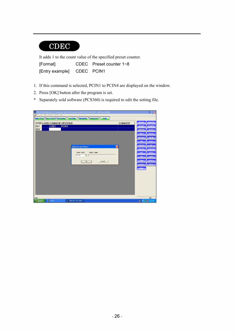
It adds 1 to the count value of the specified preset counter. [Format] CINC Preset counter 1~8 [Entry example] CINC PCIN1
1. If this command is selected, PCIN1 to PCIN4 are displayed on the window. 2. Press [OK] button after the program is set. * Separately sold software (PCS360) is required to edit the setting file.
CINC
- 26 -
It adds 1 to the count value of the specified preset counter. [Format] CDEC Preset counter 1~8 [Entry example] CDEC PCIN1
1. If this command is selected, PCIN1 to PCIN4 are displayed on the window. 2. Press [OK] button after the program is set. * Separately sold software (PCS360) is required to edit the setting file.
CDEC

- 27 -
It clears the count value of the specified preset counter. [Format] CCLR Preset counter 1~8 [Entry example] CCLR PCIN1
1. If this command is selected, PCIN1 to PCIN4 are displayed on the window. 2. Press [OK] button after the program is set. * Separately sold software (PCS360) is required to edit the setting file.
CCLR

- 28 -
It puts the unit to stand-by state until the specified time elapses. It puts the unit to stand-by state until it matches with the specified state. [Format] WAIT timer No. WAIT value [Entry example] WAIT T81 .. Puts the unit to the stand-by state until T100
completes. WAIT 1.50..... Puts the unit to the stand-by state for 1.5 second.
1. Selecting the command will display the timer that can be entered on the window. 2. Press [OK] button after the program is set. * Separately sold software (PCS360) is required to edit the setting file.
POINT T** ・・・・・・・・・・・・・・・・・・・・・・・・ Variable timer (T81 ~ T100)
NC step release timer TIME (value) ・・・・・・・・・・・・・・・・ Directly sets second. * 0.00 to 99.99 seconds can be set. POS ・・・・・・・・・・・・・・・・・・・・・・・・ It puts the unit to the stand-by state until movement
by MOVEP or HOMEP completes.
WAIT

- 29 -
Control command
It conducts branch to the specified label. [Format] GOTO label No. [Entry example] GOTO L001 .... Moves to the label No. 001.
1. Selecting the command will display "Label No:" in “Operand Input Wizard" window. 2. Press [OK] button after the program is set. * Separately sold software (PCS360) is required to edit the setting file.
POINT It conducts unconditional branches. It can also be set by IF condition setting. The label to which it branches may be in a different program.
GOTO

- 30 -
Label. It specifies the location to which the operation is branched by the GOTO or GOSUB command.
POINT L001 to L255 are used in all NC steps.
L***

- 31 -
It conducts branch to the specified program. [Format] GOSUB program No. [Entry example] GOSUB #001 .... It is branched to the program No.001.
1. Selecting the command will display “Prog No:". 2. Press [OK] button after the program is set. * Separately sold software (PCS360) is required to edit the setting file.
POINT It conducts unconditional branches. Unlike GOTO, however, it returns to the line after GOSUB by entering RET in the branch program. It can also be set by IF condition setting.
GOSUB

- 32 -
It returns to the program branched by GOSUB. [Format] RET [Entry example] RET ... It returns to the next line of the program in which GOSUB is
described.
It declares end of the program. [Format] END
POINT If it is declared at some midpoint of the program, the remainder of the program will not be executed.
RET
END

- 33 -
Starts the specified program parallelly. [Format] ON Program No. [Entry example] ON #101 .....It starts the program No. 101 parallelly.
POINT The programs that can be specified are 101 to 240 and 241 to 255.
It stops the specified program. [Format] OFF Program No. [Entry example] OFF #101 .....It stops the program No. 101.
POINT The programs that can be specified are 101 to 240 and 241 to 255.
It judges various conditions. [Format] IF [Entry example] IF SP10 ON GOSUB #101
It is branched to the program No. 101 if SP10 is ON. It goes to the next STEP No. if SP10 is OFF.
It temporarily suspends all NC programs. [Format] PAUSE ON: Stops temporarily. PAUSE OFF: Cancels temporary stop.
POINT It can be set only for programs 251 to 255.
OFF
ON
IF
PAUSE

- 34 -
It outputs the alarm. [Format] ALM alarm No. [Entry example] ALM 55 .....It outputs the alarm No.55.
POINT It outputs the buzzer. The message is also displayed on the pendant. * The message number corresponds to the set number + 200. Use 1 to 55 because
messages of 56 or later are output as standard.
List of connection symbols Symbol Meaning Available commands
, (comma) AND IN, OUT, MOVE, MOVEP, HOME, HOMEP, IF, PATH, BREAK, SPEED
or OR IN, IF = match, substitution IF, OUT (Only = is used.) > Larger < Smaller # Do not match
ALM
- 35 -
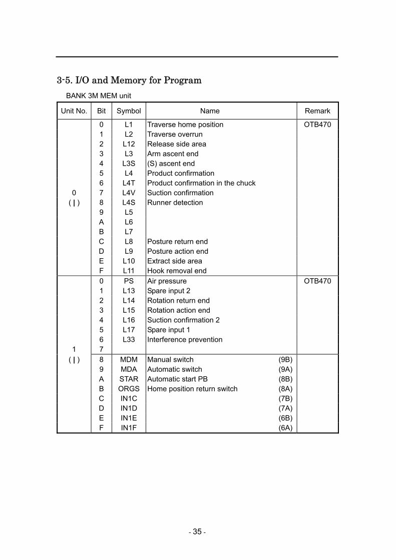
3-5. I/O and Memory for Program BANK 3M MEM unit
Unit No. Bit Symbol Name Remark
0 L1 Traverse home position OTB470 1 L2 Traverse overrun 2 L12 Release side area 3 L3 Arm ascent end 4 L3S (S) ascent end 5 L4 Product confirmation 6 L4T Product confirmation in the chuck
0 7 L4V Suction confirmation ( | ) 8 L4S Runner detection
9 L5 A L6 B L7 C L8 Posture return end D L9 Posture action end E L10 Extract side area F L11 Hook removal end 0 PS Air pressure OTB470 1 L13 Spare input 2 2 L14 Rotation return end 3 L15 Rotation action end 4 L16 Suction confirmation 2 5 L17 Spare input 1 6 L33 Interference prevention
1 7 ( | ) 8 MDM Manual switch (9B)
9 MDA Automatic switch (9A) A STAR Automatic start PB (8B) B ORGS Home position return switch (8A) C IN1C (7B) D IN1D (7A) E IN1E (6B) F IN1F (6A)
- 36 -
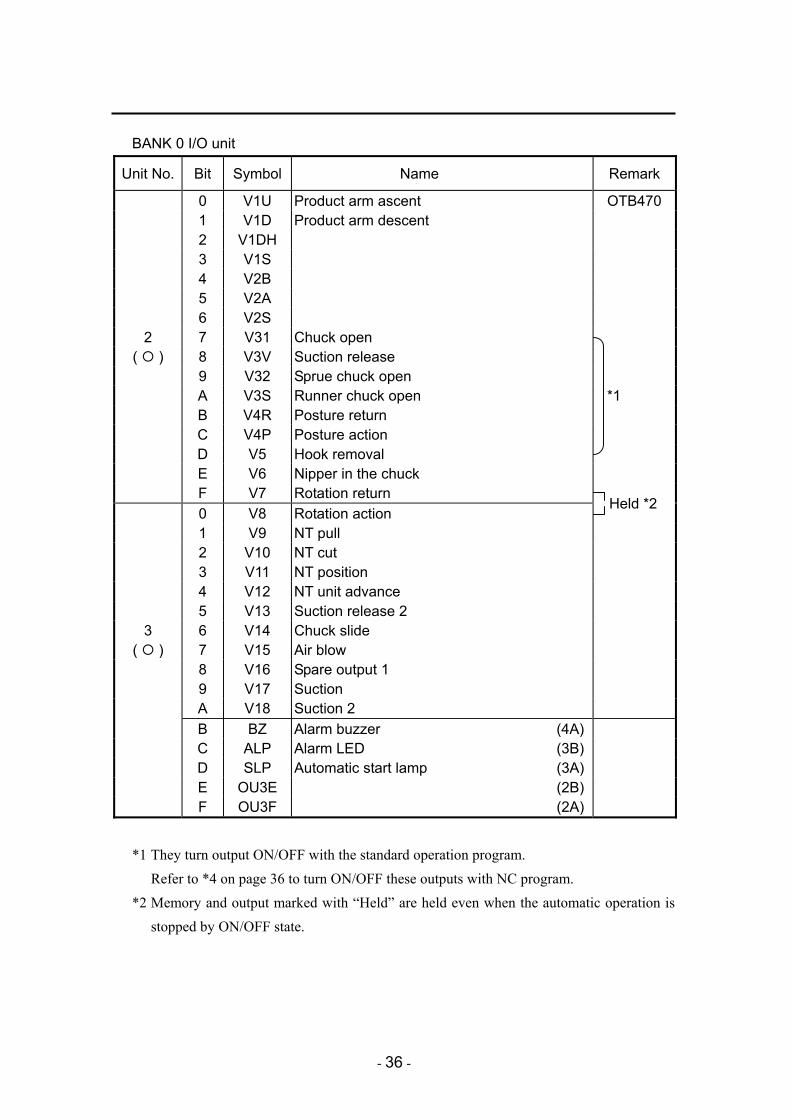
BANK 0 I/O unit
Unit No. Bit Symbol Name Remark
0 V1U Product arm ascent OTB470 1 V1D Product arm descent 2 V1DH 3 V1S 4 V2B 5 V2A 6 V2S
2 7 V31 Chuck open ( ) 8 V3V Suction release
9 V32 Sprue chuck open A V3S Runner chuck open *1 B V4R Posture return C V4P Posture action D V5 Hook removal E V6 Nipper in the chuck F V7 Rotation return 0 V8 Rotation action 1 V9 NT pull 2 V10 NT cut 3 V11 NT position 4 V12 NT unit advance 5 V13 Suction release 2
3 6 V14 Chuck slide ( ) 7 V15 Air blow
8 V16 Spare output 1 9 V17 Suction A V18 Suction 2 B BZ Alarm buzzer (4A) C ALP Alarm LED (3B) D SLP Automatic start lamp (3A) E OU3E (2B) F OU3F (2A)
*1 They turn output ON/OFF with the standard operation program.
Refer to *4 on page 36 to turn ON/OFF these outputs with NC program. *2 Memory and output marked with “Held” are held even when the automatic operation is
stopped by ON/OFF state.
Held *2

- 37 -
BANK 0 I/O unit
Unit No. Bit Symbol Name Remark
0 MD Safety door close PI360 1 MO Mold open complete 2 MC Mold close complete 3 ME Ejector end 4 MN Defective product signal 5 RD Release side descent command 6 OD Release side safety door close
4 7 SP7 ( | ) 8 MA Molding machine automatic PI360
9 SP10 A B C D E F 0 H100 Mold replacement request (9B) PI360 1 H109 Mold No. set (9A) SIOF88 2 H110 Setting start (8B) CON B 3 H111 Unloader operation allowed (8A) 4 H112 Error reset (7B) 5 (7A) 6 (6B)
5 7 (6A) ( | ) 8 H101 Mold No. 27 (9B) PI360
9 26 (9A) SIOF88 A 25 (8B) CON C B 24 (8A) C 23 (7B) D 22 (7A) E 21 (6B) F 20 (6A)

- 38 -
BANK 0 I/O unit
Unit No. Bit Symbol Name Remark
0 RY1 Mold open safely PI360 1 RY2 Mold close safely 2 RY3 Cycle start 3 RY4 4 RY5 Alarm 5 RY6 Jig start 6 RY7 Ejector advance
6 7 RY8 ( ) 8
9 A B C D E F 0 H130 Mold replacement allowed (5B) PI360 1 H131 Setting error (5A) SIOF88 2 H132 Setting complete (4B) CON B 3 H133 Setting operating (4A) 4 (3B) 5 (3A) 6 (2B)
7 7 (2A) ( ) 8 H134 Mold No. answer 2 (5B) PI360
9 2 (5A) SIOF88 A 2 (4B) CON C B 2 (4A) C 2 (3B) D 2 (3A) E 2 (2B) F 2 (2A)
- 39 -
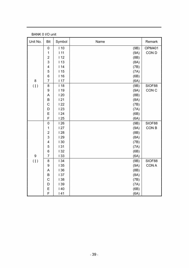
BANK 0 I/O unit
Unit No. Bit Symbol Name Remark
0 I 10 (9B) OPM401 1 I 11 (9A) CON D 2 I 12 (8B) 3 I 13 (8A) 4 I 14 (7B) 5 I 15 (7A) 6 I 16 (6B)
8 7 I 17 (6A) ( | ) 8 I 18 (9B) SIOF88
9 I 19 (9A) CON C A I 20 (8B) B I 21 (8A) C I 22 (7B) D I 23 (7A) E I 24 (6B) F I 25 (6A) 0 I 26 (9B) SIOF88 1 I 27 (9A) CON B 2 I 28 (8B) 3 I 29 (8A) 4 I 30 (7B) 5 I 31 (7A) 6 I 32 (6B)
9 7 I 33 (6A) ( | ) 8 I 34 (9B) SIOF88
9 I 35 (9A) CON A A I 36 (8B) B I 37 (8A) C I 38 (7B) D I 39 (7A) E I 40 (6B) F I 41 (6A)
- 40 -
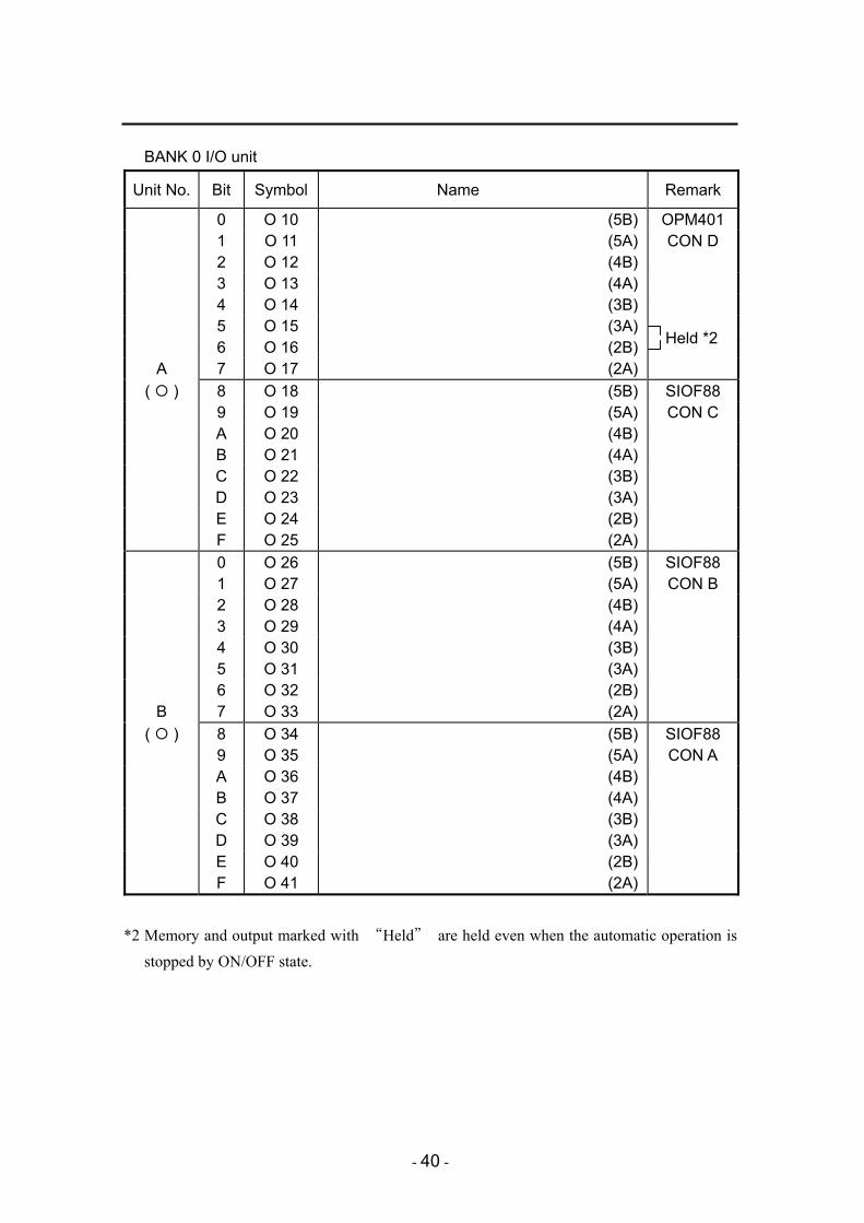
BANK 0 I/O unit
Unit No. Bit Symbol Name Remark
0 O 10 (5B) OPM401 1 O 11 (5A) CON D 2 O 12 (4B) 3 O 13 (4A) 4 O 14 (3B) 5 O 15 (3A) 6 O 16 (2B)
A 7 O 17 (2A) ( ) 8 O 18 (5B) SIOF88
9 O 19 (5A) CON C A O 20 (4B) B O 21 (4A) C O 22 (3B) D O 23 (3A) E O 24 (2B) F O 25 (2A) 0 O 26 (5B) SIOF88 1 O 27 (5A) CON B 2 O 28 (4B) 3 O 29 (4A) 4 O 30 (3B) 5 O 31 (3A) 6 O 32 (2B)
B 7 O 33 (2A) ( ) 8 O 34 (5B) SIOF88
9 O 35 (5A) CON A A O 36 (4B) B O 37 (4A) C O 38 (3B) D O 39 (3A) E O 40 (2B) F O 41 (2A)
*2 Memory and output marked with “Held” are held even when the automatic operation is stopped by ON/OFF state.
Held *2

- 41 -
BANK 3M MEM unit
Unit No. Bit Symbol Name Remark
0 MMOPS NC step release memory (one cycle) 1 MMME NC step release memory (ejector end) 2 MFALM NC step release memory (production end) 3 MPEND NC step release memory
(production end advance notice)
4 MIRUP NC step release memory (initial defective product ejection UP)
5 MSMUP NC step release memory (sample operation UP) 6 MXSTP NC step release memory (sample stopping)
0 7 M007 NC step release memory ( R ) 8 M008 NC step release memory
9 M009 NC step release memory A M00A NC step release memory B M00B NC step release memory C M00C NC step release memory D M00D NC step release memory E M00E NC step release memory F M00F NC step release memory 0 M010 NC step release memory 1 MOCYL NC step release memory (all cycles) 2 MTCYL NC step release memory (unloading time) 3 MWINC NC step release memory (count the number to
unload)
4 MIRIN NC step release memory (count the defective product ejection)
5 MSMIN NC step release memory (count the initial defective product ejection)
6 MRLIN NC step release memory (count the sample operation)
1 7 MMAL NC step release memory (master stop) ( R ) 8 MDELE NC step release memory
(automatic and home position return stop)
9 M019 NC step release memory A M01A NC step release memory B MV4R Posture return C MV4P Posture action D MCC Product chuck close E MV32 Sprue chuck close F MV3S Runner chuck close
*3 It refers to memory that can be used with NC step program. Use it according to purposes. *4 Use this type of memory when turning ON/OFF the output of posture action, return and
chuck close with NC program.
*3
*3
*4

- 42 -
BANK 3M MEM unit
Unit No. Bit Symbol Name Remark
0 M020 NC step release memory 1 M021 NC step release memory 2 M022 NC step release memory 3 M023 NC step release memory 4 M024 NC step release memory 5 M025 NC step release memory 6 M026 NC step release memory
2 7 M027 NC step release memory ( R ) 8 M028 NC step release memory
9 M029 NC step release memory A M02A NC step release memory B M02B NC step release memory C M02C NC step release memory D M02D NC step release memory E M02E NC step release memory F M02F NC step release memory 0 M030 NC step release memory 1 M031 NC step release memory 2 M032 NC step release memory 3 M033 NC step release memory 4 M034 NC step release memory 5 M035 NC step release memory 6 M036 NC step release memory
3 7 M037 NC step release memory ( R ) 8 M038 NC step release memory
9 M039 NC step release memory A M03A NC step release memory B M03B NC step release memory C M03C NC step release memory D M03D NC step release memory E M03E NC step release memory F M03F NC step release memory
*2 Memory and output marked with “Held” are held even when the automatic operation is stopped by ON/OFF state. (Example) Turning ON M020 will turn OFF the other M021 and tuning ON M021 will turn
OFF M020. This is applicable to other sections to be held.
Held *2
Held
Held
Held
Held
Held
Held
Held
Held
Held
Held
Held
Held
Held
Held
Held

- 43 -
BANK 3M MEM unit
Unit No. Bit Symbol Name Remark
0 M040 NC step release memory 1 M041 NC step release memory 2 M042 NC step release memory 3 M043 NC step release memory 4 M044 NC step release memory 5 M045 NC step release memory 6 M046 NC step release memory
4 7 M047 NC step release memory ( R ) 8 M048 NC step release memory
9 M049 NC step release memory A M04A NC step release memory B M04B NC step release memory C M04C NC step release memory D M04D NC step release memory E M04E NC step release memory F M04F NC step release memory 0 M050 NC step release memory 1 M051 NC step release memory 2 M052 NC step release memory 3 M053 NC step release memory 4 M054 NC step release memory 5 M055 NC step release memory 6 M056 NC step release memory
5 7 M057 NC step release memory ( R ) 8 M058 NC step release memory
9 M059 NC step release memory A M05A NC step release memory B M05B NC step release memory C M05C NC step release memory D M05D NC step release memory E M05E NC step release memory F M05F NC step release memory

- 44 -
BANK 3M MEM unit
Unit No. Bit Symbol Name Remark
0 M060 NC step release memory 1 M061 NC step release memory 2 M062 NC step release memory 3 M063 NC step release memory 4 M064 NC step release memory 5 M065 NC step release memory 6 M066 NC step release memory
6 7 M067 NC step release memory ( R ) 8 M068 NC step release memory
9 M069 NC step release memory A M06A NC step release memory B M06B NC step release memory C M06C NC step release memory D M06D NC step release memory E M06E NC step release memory F M06F NC step release memory 0 M070 NC step release memory 1 M071 NC step release memory 2 M072 NC step release memory 3 M073 NC step release memory 4 M074 NC step release memory 5 M075 NC step release memory 6 M076 NC step release memory
7 7 M077 NC step release memory ( R ) 8 M078 NC step release memory
9 M079 NC step release memory A M07A NC step release memory B M07B NC step release memory C M07C NC step release memory D M07D NC step release memory E M07E NC step release memory F M07F NC step release memory

- 45 -
3-6. Flow of the Program

- 46 -
4. NC POINT SETTING
POINT It can be set only when the select switch is set to the manual operation.
4-1. Display of NC Point Setting Screen 1. Select [MENU]-[SYSTEM],
and [INTERRUPT NC PROGRAM] button is set in use.
1. Select [MENU]-[NC STEP]-[NC POINT
SET].
→ NC POINT P001 screen is displayed.

- 47 -
4-2. NC Point Setting Enter the values as follows;
Action setting method・・・・・・Sheet key entry (fine adjustment) Value setting method ・・・・・・Entry by ten keys and [+] or [-] button
Action setting method 1. Move the orange cursor with
keys to the axis required.
* Press (previous point) (next
point) keys to show the other point setting screens.
Or, press key to switch to the point
selection screen.
2. Press or key while keeping
pressed the operable key to move the axis to the position required.
........... Moves the axis to the
opposite direction of the home position
........... Moves the axis to the
direction of the home position
3. Press key to show (position
memory) (group memory) keys on
the screen.
4. Press (group memory) key to
memorize the current positions when the moving has been completed.

- 48 -
* Press (position memory) key to
memorize only one axis which the cursor indicates.
CAUTION Please confirm that the current position and the setting value for that are exactly
the same after using (position memory) (group memory) keys to memorize the position.

- 49 -
Value entry method
POINT
Only keys are available when changing the values under the automatic operation. Furthermore, only digits of less than 1 mm can be changed in that case.
1. Move the orange cursor with keys to the axis required. * The value will turn yellow if the axis
completes to move to the point shown by the unloader.
* Press (previous point) (next
point) keys to show the other point on
another page. Or, Press key to
switch to the point selection screen.
2. Input values using ten keys or
keys.
CAUTION Be sure to confirm the operation of the unloader by manual operation or step operation before starting the automatic operation when each point position was changed by the value setting method.
Be sure to set the speed to minimum when each point position was changed.

- 50 -
5. NC PACKAGING The order to set the products extracted from the molding machine in the conveyor or box and to release them can be set as explained in this chapter.
POINT • The points that can be set by NC packaging are up to 255 for each axis. • The points for free packaging is included in the points for NC free packaging.
Therefore, the total points should be up to 255 for both. • Be sure to create the instruction to “change the box” in the interrupt program. • The NC program does not start unless [NC program] in the mode setting is ON. • Refer to “4-10. Packaging Setting” in “Operational Edition” for details of packaging.
- 51 -
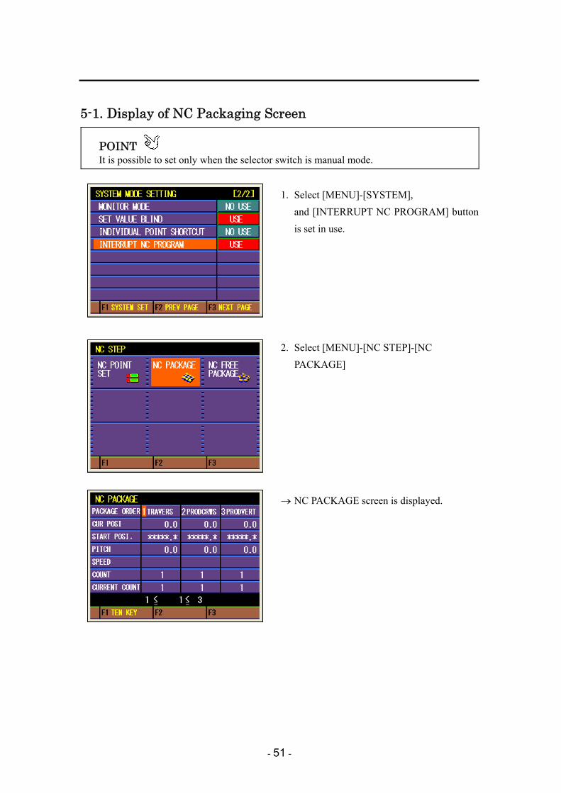
5-1. Display of NC Packaging Screen
POINT It is possible to set only when the selector switch is manual mode.
1. Select [MENU]-[SYSTEM],
and [INTERRUPT NC PROGRAM] button is set in use.
2. Select [MENU]-[NC STEP]-[NC
PACKAGE]
→ NC PACKAGE screen is displayed.
- 52 -
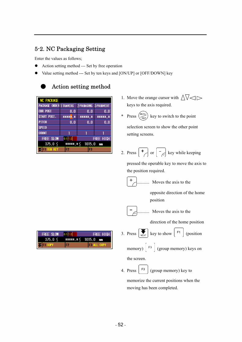
5-2. NC Packaging Setting Enter the values as follows;
Action setting method --- Set by free operation
Value setting method --- Set by ten keys and [ON/UP] or [OFF/DOWN] key
● Action setting method
1. Move the orange cursor with keys to the axis required.
* Press key to switch to the point
selection screen to show the other point setting screens.
2. Press or key while keeping
pressed the operable key to move the axis to the position required.
........... Moves the axis to the
opposite direction of the home position
........... Moves the axis to the
direction of the home position
3. Press key to show (position
memory) (group memory) keys on
the screen.
4. Press (group memory) key to
memorize the current positions when the moving has been completed.

- 53 -
* Press (position memory) key to
memorize only one axis which the cursor indicates.
CAUTION Please confirm that the current position and the setting value for that are exactly
the same after using (position memory) (group memory) keys to memorize the position.

- 54 -
Value entry method
POINT
Only keys are available when changing the values under the automatic operation. Furthermore, only digits of less than 1 mm can be changed in that case.
1. Move the orange cursor with keys to the axis required. * The value will turn yellow if the axis
completes to move to the point shown by the unloader.
* Press key to switch to the point
selection screen to show the other point on another page.
2. Input values using ten keys or
keys.
CAUTION Be sure to confirm the operation of the unloader by manual operation or step operation before starting the automatic operation when each point position was changed by the value setting method.
Be sure to set the speed to minimum when each point position was changed.

- 55 -
5-3. NC Free Packaging
5-3-1. Display of NC free packaging screen
POINT It is possible to set only when the selector switch is manual mode.
1. Select [MENU]-[SYSTEM],
and [INTERRUPT NC PROGRAM] button is set in use.
2. Select [MENU]-[NC STEP]-[NC FREE
PACKAGE]
→ NC FREE PACKAGE screen is displayed.

- 56 -
5-3-2. NC free packaging setting
Enter the values as follows; Action setting method ・・・・・・・Sheet key input (fine adjustment) Value setting method ・・・・・・・・Enter by ten keys and [+] or [-] button
* Refer to “5-2 NC Packaging Setting” as for entry method of each value.

- 57 -
6. FREE OPERATION The details of PROG No. 201 to 216 set with NC step can be confirmed with operation of buttons. Pressing this button will execute the created program.
POINT * For example, it can be used for turning ON and OFF the valve.
1. Select [MENU]-[SYSTEM],
and [INTERRUPT NC PROGRAM] button is set in use.
2. Select [MENU]-[FREE OPERATION], and
press the [NC FREE OPE] key.

- 58 -
→ NC PACKAGE screen is displayed. Move the red cursor with keys to the key that you want to operate, and display it.
* NC manual 201…RPOG#201 Operates while this button is pressed.
NC manual 216…RPOG#216 Operates while this button is pressed.
3. Press the operable key and (NC
free) key to operate the valve, etc.

- 59 -
7. PROGRAM SAMPLE
Case-1 Rotation operation (when the rotation unit is installed on the chuck plate)
The input and output signals in OTB470 is used with this sample. L14: rotation return end input, L15: Rotation action end input, V7: Rotation return output, V8: Rotation action output Interrupt program No.8
STEP LAB COM OPE Details PROG #008 001 OUT V7 OFF, V8 ON Rotation start output 002 WAIT T82 T82 setting time stand-by 003 IF L15 OFF GOTO L120 Error when rotation action end is OFF 004 IF L14 ON GOTO L120 Error when rotation return end is ON 005 END END
- 60 -
Interrupt program No.9 STEP LAB COM OPE Details
PROG #009 001 OUT V7 ON, V8 OFF Rotation return output 002 WAIT T81 T81 setting time stand-by 003 IF L14 OFF GOTO L121 Error when rotation return end is OFF 004 IF L15 ON GOTO L121 Error when rotation action end is ON 005 END END
Rotation return operation (free operation) program No. 201
STEP LAB COM OPE Details PROG #201 001 OUT V8 OFF 002 OUT V7 ON Rotation return output 003 END END
Rotation action operation (free operation) program No. 202
STEP LAB COM OPE Details PROG #202 001 OUT V7 OFF 002 OUT V8 ON Rotation action output 003 END END
Home position return program No. 241
STEP LAB COM OPE Details PROG #241 001 IF L3 ON GOTO L001 Ascent end check 002 IF L12 OFF GOTO L119 Home position return disabled when drop
side area is OFF 003 HOME A4 A4 (vertical) home position return 004 IN L3 ON Ascent end waiting 005 L001 OUT MV4R ON, MV4P OFF Posture return output 006 IN L8 ON, L9 OFF Posture return end check 007 WAIT 0.10 0.10 second stand-by 008 OUT V7 ON, V8 OFF Rotation return output 009 WAIT T81 T81 set time stand-by 010 IF L15 OFF GOTO L121 Error when rotation action end is OFF 011 IF L14 ON GOTO L121 Error when rotation return end is ON 012 END END

- 61 -
Home position return disabled program No. 251 STEP LAB COM OPE Details
PROG #251 001 L119 ALM 1 Alarm 1 (201) output 002 OUT MDELE ON Operation stop output 003 GOTO L119 004 END END
Rotation action error program No. 252
STEP LAB COM OPE Details PROG #252 001 L120 ALM 2 Alarm 2 (202) output 002 OUT MDELE ON Operation stop output 003 GOTO L120 004 END END
Rotation return error program No. 253
STEP LAB COM OPE Details PROG #253 001 L121 ALM 3 Alarm 3 (203) output 002 OUT MDELE ON Operation stop output 003 GOTO L121 004 END END

- 62 -
Case-2 Gate cut system (Gate cut for 5 locations)
SIOF88 is added to PI360 for this sample. O01: Nipper cut output
Interrupt program No. 16 STEP LAB COM OPE Details
PROG #016 001 SPEED 70 Speed 70 % specification 002 OUT M020 OFF, M021 ON Gate cut area advance memory ON 003 MOVE A1, A2 P001 A1 (traverse), A2 (crosswise) P001
movement 004 MOVE A4 P001 A4 (vertical) P001 movement 005 SPEED 15 Speed 15 % specification 006 MOVE A2 P002 A2 (crosswise) P002 movement (the first
time) 007 WAIT T81 T81 set time stand-by 008 OUT O 01 ON Nipper cut output 009 WAIT T82 T82 set time stand-by 010 OUT O 01 OFF Nipper cut output OFF 011 WAIT T83 T83 set time stand-by 012 MOVE A2 P003 A2 (crosswise) P003 movement 013 SPEED 70 Speed 70 % specification
- 63 -
STEP LAB COM OPE Details 014 MOVE A1, A4 P003 A1 (traverse), A4 (vertical) P003
movement 015 SPEED 15 Speed 15 % specification 016 MOVE A2 P004 A2 (crosswise) P004 movement (the
second time) 017 WAIT T81 T81 set time stand-by 018 OUT O 01 ON Nipper cut output 019 WAIT T82 T82 set time stand-by 020 OUT O 01 OFF Nipper cut output OFF 021 WAIT T83 T83 set time stand-by 022 MOVE A2 P005 A2 (crosswise) P005 movement 023 SPEED 70 Speed 70 % specification 024 MOVE A1, A4 P005 A1 (traverse), A4 (vertical) P005
movement 025 SPEED 15 Speed 15 % specification 026 MOVE A2 P006 A2 (crosswise) P006 movement (the
third time) 027 WAIT T81 T81 set time stand-by 028 OUT O 01 ON Nipper cut output 029 WAIT T82 T82 set time stand-by 030 OUT O 01 OFF Nipper cut output OFF 031 WAIT T83 T83 set time stand-by 032 MOVE A2 P007 A2 (crosswise) P007 movement 033 SPEED 70 Speed 70 % specification 034 MOVE A1, A4 P007 A1 (traverse), A4 (vertical) P007
movement 035 SPEED 15 Speed 15 % specification 036 MOVE A2 P008 A2 (crosswise) P008 movement (the
fourth time) 037 WAIT T81 T81 set time stand-by 038 OUT O 01 ON Nipper cut output 039 WAIT T82 T82 set time stand-by 040 OUT O 01 OFF Nipper cut output OFF 041 WAIT T83 T83 set time stand-by 042 MOVE A2 P009 A2 (crosswise) P009 movement 043 SPEED 70 Speed 70 % specification 044 MOVE A1, A4 P009 A1 (traverse), A4 (vertical) P009
movement 045 SPEED 15 Speed 15 % specification 046 MOVE A2 P010 A2 (crosswise) P010 movement (the fifth
time) 047 WAIT T81 T81 set time stand-by 048 OUT O 01 ON Nipper cut output 049 WAIT T82 T82 set time stand-by 050 OUT O 01 OFF Nipper cut output OFF 051 WAIT T83 T83 set time stand-by 052 MOVE A2 P011 A2 (crosswise) P011 movement 053 SPEED 70 Speed 70 % specification

- 64 -
STEP LAB COM OPE Details 054 MOVE A1, A4 P011 A1 (traverse), A4 (vertical) P011
movement 055 SPEED 100 Speed 100 % specification 056 MOVE A1, A2, A4 P012 A1, A2, A4P012 movement 057 OUT M020 ON, M021 OFF Gate cut area advance memory OFF 058 END END
Free operation program No. 201
STEP LAB COM OPE Details PROG #201 001 OUT O 01 ON Nipper cut output 002 END END
Home position return program No. 241
STEP LAB COM OPE Details PROG #241 001 IF M020 ON GOTO L110 Gate cut area advance memory OFF 002 IF L12 OFF GOTO L110 Drop side area OFF check 003 IF L3 ON GOTO L110 Ascent end ON check 004 IF L9 ON GOTO L110 Posture action end ON check 005 IF MORG OFF GOTO
L119 Return disabled when home position returned is OFF
006 SPEED 15 Speed 15 % specification 007 MOVE A2 P011 A2 (crosswise) P011 movement 008 HOME A4 A4 (vertical) home position return 009 IN L3 ON Ascent end waiting 010 L110 OUT M020 ON Gate cut area advance memory OFF 011 END END
Home position return disabled program No. 251
STEP LAB COM OPE Details PROG #251 001 L119 ALM 1 002 OUT MDELE ON Alarm 1 (201) output 003 GOTO L119 Operation stop output 004 END END

- 65 -
Case-3 Two point release operation
Input and output signals in OTB470 is used with this sample. L13: Product check 2 input, V13: Chuck open output
Chuck open, L13-OFF check Interrupt program No.1
STEP LAB COM OPE Details PROG #001 001 IF L13 ON GOTO L119 Error when product confirmation 2 is ON002 END END
Interrupt program No.2 STEP LAB COM OPE Details
PROG #002 001 OUT V13 ON Product chuck 2 open output 002 WAIT 0.50 0.50 second stand-by 003 END END

- 66 -
Chuck close Interrupt program No.6
STEP LAB COM OPE Details PROG #006 001 OUT V13 OFF Product chuck 2 close 002 WAIT T82 T82 set time stand-by 003 END END
Home position return program no.9 STEP LAB COM OPE Details
PROG #009 001 IF L13 OFF GOTO L119 Error when product check 2 is OFF 002 ON #101 Product check 2 monitor program start 003 END END
Product release operation Interrupt program No.19
STEP LAB COM OPE Details PROG #019 001 SPEED 30 Speed 30 % specification 002 MOVE A4 P001 A4 (vertical) P001 movement 003 MOVE A1, A2 P002 A1 (traverse), A2 (crosswise) P002
movement 004 MOVE A4 P002 A4 (vertical) P002 movement 005 WAIT 0.30 0.30 second stand-by 006 OUT V13 ON Product chuck 2 open output 007 WAIT T81 T81 set time stand-by 008 END END
Product check 2 monitor program No. 101 STEP LAB COM OPE Details
PROG #101 001 L001 IF V13 ON GOTO L003 Product chuck 2 open complete 002 IF L13 ON GOTO L001 Product check 2 ON check 003 WAIT 0.10 0.10 second stand-by 004 IF L13 OFF GOTO L119 Error when product check 2 is OFF 005 GOTO L001 006 L003 END END

- 67 -
Free operation program No. 201 STEP LAB COM OPE Details
PROG #201 001 OUT V13 ON Product chuck 2 open output 002 END END
Monitor program Product check 2 error program No. 251
STEP LAB COM OPE Details PROG #251 001 L119 ALM 1 Alarm 1 output 002 OFF #101 Product check 2 monitor program
complete 003 OUT MDELE ON Automatic stop output 004 GOTO L119 005 END END
- 68 -
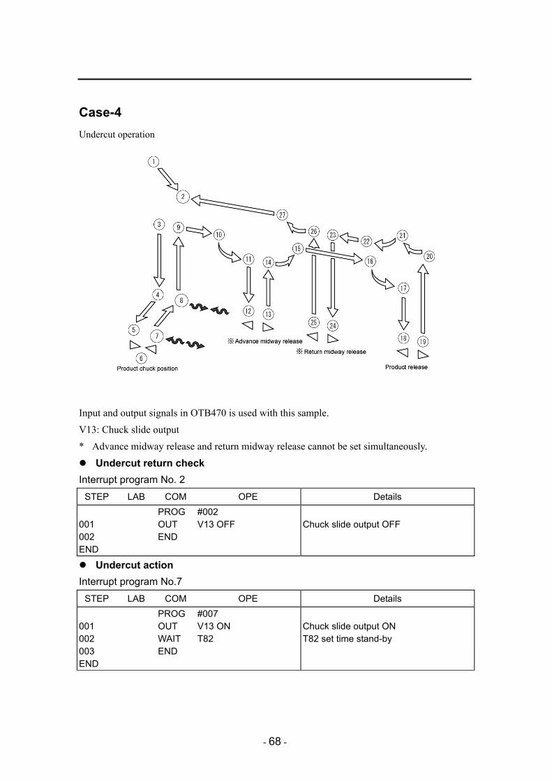
Case-4 Undercut operation
Input and output signals in OTB470 is used with this sample. V13: Chuck slide output * Advance midway release and return midway release cannot be set simultaneously.
Undercut return check Interrupt program No. 2
STEP LAB COM OPE Details PROG #002 001 OUT V13 OFF Chuck slide output OFF 002 END END
Undercut action Interrupt program No.7
STEP LAB COM OPE Details PROG #007 001 OUT V13 ON Chuck slide output ON 002 WAIT T82 T82 set time stand-by 003 END END

- 69 -
Undercut return Interrupt program No.8
STEP LAB COM OPE Details PROG #008 001 OUT V13 OFF Chuck slide output OFF 002 WAIT T83 T83 set time stand-by 003 END END
Free operation program No. 201 STEP LAB COM OPE Details
PROG #201 001 OUT V13 ON Chuck slide output ON 002 END END
Home position return program No. 241 STEP LAB COM OPE Details
PROG #241 001 OUT V13 OFF Chuck slide output OFF 002 WAIT T83 T83 set time stand-by 003 END END

- 70 -
Case-5 Hinge operation
Input and output signals in OTB470 is used with this sample. V13: Hinge output
Hinge return check Interrupt program No. 2
STEP LAB COM OPE Details PROG #002 001 OUT V13 OFF, M030 OFF Hinge output OFF, Complete memory
OFF 002 END END
Hinge operation start Interrupt program No. 9
STEP LAB COM OPE Details PROG #009 001 ON #101 Hinge operation program start 002 END END

- 71 -
Hinge operation program Hinge operation program No. 101
STEP LAB COM OPE Details
PROG #101 001 OUTP PCLR1 Preset counter reset 002 L100 OUT V13 ON Hinge output ON 003 WAIT T82 T82 set time stand-by 004 OUT V13 OFF Hinge output OFF 005 WAIT T83 T83 set time stand-by 006 OUTP PCIN1 Counter +1 007 IF PCUP1 OFF GOTO L100 Counter up check 008 OUT M030 ON Hinge complete memory ON 009 END END
Hinge operation complete Interrupt program No.16
STEP LAB COM OPE Details PROG #016 001 IN M030 ON Hinge complete memory waiting 002 OUT M030 OFF Hinge complete memory OFF 003 END END
Free operation program No. 201 STEP LAB COM OPE Details
PROG #201 001 OUT V13 ON Hinge output ON 002 END END
Home position return Home position return program No. 241
STEP LAB COM OPE Details PROG #241 001 OUT V13 OFF, M030 OFF Hinge output OFF, complete memory
OFF 002 WAIT T83 T83 set time stand-by 003 OUTP PCLR1 Preset counter reset 004 END END

- 72 -
Case-6 Insert supply operation
SIOF88 is added to PI360 and input and output signals in OTB470 is used with this sample. I01: Start SW input, I03: Slide table return end input, I04: Slide table action source input O01: Slide table return output, O02: Slide table action output L13: Insert check input L16: Pusher return end input, L17: Pusher action end input V13: Insert chuck open output, V17: Pusher action output P001: Insert receive position, P002: Insert receive ascent position P003: Insert insertion position, P004: Insert insertion return position

- 73 -
Chuck open, L13-OFF and L16-ON check, Program No. 101, 103, 104, and 105 start
Interrupt program No. 1 STEP LAB COM OPE Details
PROG #001 001 OUT V13 ON, V17 OFF, O 01
ON, O 02 OFF, M030 OFF, M031 OFF
Insert chuck open, Pusher return Slide table return, Memory OFF
002 WAIT 2.00 2.00 seconds stand-by 003 IF L13 OFF, L16 ON,
L17 OFF GOTO L001 Insert chuck input check
004 GOSUB #251 Error when a failure occurs 005 L001 IF I 01 OFF, I 03 ON, I 04
OFF GOTO L002 Insert supplier input program
006 GOSUB #252 Error when a failure occurs 007 L002 ON #101 Insert supplier operation program start 008 ON #103 Table action monitor program start 009 ON #104 Table return monitor program start 010 ON #105 Insert monitor program start 011 IN L3 ON Ascent end input waiting 012 OUT M033 ON Automatic initial memory ON 013 GOSUB #102 Insert workpiece receiving program
branch 014 END END
Insert workpiece operation program Interrupt program No. 20
STEP LAB COM OPE Details PROG #020 001 GOSUB #102 Insert workpiece receiving program
branch 002 END END

- 74 -
Insert workpiece supplier operation program Insert supplier operation program No. 101
STEP LAB COM OPE Details PROG #101 001 IF I 03 ON GOTO L003 Table return end check 002 L004 OUT O 01 ON, O 02 OFF Table return output 003 WAIT T82 T82 set time stand-by 004 IN I 03 ON Table return end check 005 L003 IN I 01 ON Set complete switch 006 OUT O 01 OFF, O 02 ON Table action output 007 WAIT T83 T83 set time stand-by 008 IN I 04 ON Table action end check 009 OUT M030 ON Transfer preparation OK ON 010 IN M031 ON Receiving complete input waiting 011 OUT M030 OFF Transfer preparation OK OFF 012 GOTO L004 013 END END
Unloader insert workpiece receiving operation program Insert workpiece receiving program No. 102
STEP LAB COM OPE Details PROG #102 001 SPEED 70 Speed 70 % specification 002 OUT V5 ON Vertical hook return output 003 MOVE A1, A2 P001 A1 (traverse), A2 (crosswise) P001
movement 004 IF L9 ON GOTO L005 Posture action end check 005 OUT MV4R OFF, MV4P ON Posture action output 006 IN L9 ON Posture action end check 007 L005 IN M030 ON Transfer preparation OK waiting 008 SPEED 30 Speed 30 % specification 009 MOVE A4 P001 A4 (vertical) P001 movement 010 OUT V13 OFF Insert chuck close 011 WAIT T84 T84 set time stand-by 012 SPEED 50 Speed 50 % specification 013 MOVE A4 P002 A4 (vertical) P002 movement 014 IF L3 OFF GOSUB #253 Ascent end check 015 IF L13 OFF GOSUB #254 Insert workpiece check 016 OUT M031 ON Receiving complete output 017 IF M033 OFF GOTO L006 Automatic initial memory check 018 OUT MV4P OFF, MV4R ON Posture return output 019 IN L8 ON Posture return end check 020 L006 OUT M031 OFF, M033 OFF Initial memory and receiving completion
OFF 021 RET END

- 75 -
Insert supply operation to mold Interrupt program No. 8
STEP LAB COM OPE Details PROG #008 001 SPEED A4 20, A2 10 SpeedA4 20%, A2 10% specification 002 MOVE A4 P003 A4 (vertical) P003 movement 003 MOVE A2 P003 A2 (crosswise) P03 movement 004 OUT V13 ON, V17 ON Insert chuck open, pusher action output 005 IN L17 ON or M034 ON Pusher action waiting 006 OUT V17 OFF Pusher return output 007 IN L16 ON Pusher return end check 008 MOVE A2 P004 A2 (crosswise) P004 movement 009 IF M034 ON GOSUB #251 Error when pusher action is defective 010 END END
Table action monitor program No. 103 (Processed as an error when it does not operate in 5 seconds)
STEP LAB COM OPE Details PROG #103 001 L202 OUT M070=0 Variable (M070 to 077) initial value
substitution 002 L200 IF O 01 OFF GOTO L202 Table return output check 003 WAIT 1.00 1.00 second stand-by 004 IF I 03 ON GOTO L202 Table return end check 005 INC M070 Variable (M070 to 077) +1 006 IF M070=5 GOSUB #252 Variable (M070 to 077) = 5 error 007 GOTO L200 008 RET END
Table action monitor program No. 104 (Processed as an error when it does not operate in 5 seconds)
STEP LAB COM OPE Details PROG #104 001 L204 OUT M078=0 Variable (M078 to 07F) initial value
substitution 002 L206 IF O 02 OFF GOTO L204 Table return output check 003 WAIT 1.00 1.00 second stand-by 004 IF I 04 ON GOTO L204 Table return end check 005 INC M078 Variable (M078 to 07F) +1 006 IF M078=5 GOSUB #252 Variable (M078 to 07F) = 5 error 007 GOTO L206 008 RET END

- 76 -
Insert monitor program No. 105 STEP LAB COM OPE Details
PROG #105 001 L210 IF V17 OFF GOTO L210 Pusher action output check 002 WAIT T85 T85 set time stand-by 003 IF V17 OFF GOTO L210 Pusher action output check 004 IF L17 OFF GOTO L211 Pusher action end check 005 GOTO L210 006 L211 OUT M034 ON Pusher defective memory output 007 END END
Free operation program No. 201 (A series of pusher operation) STEP LAB COM OPE Details
PROG #201 001 OUT V13 ON, V17 ON Insert chuck open, pusher action output 002 WAIT 2.00 2.00 seconds stand-by 003 OUT V17 OFF Pusher action output OFF 004 END END
Free operation program No. 202 (Insert chuck open) STEP LAB COM OPE Details
PROG #202 001 OUT V13 ON Inset chuck open 002 END END
Free operation program No. 203 (Supplier table return) STEP LAB COM OPE Details
PROG #203 001 IN L3 ON or L12 OFF Unloader safe position check 002 OUT O 02 OFF, O 01 ON Table return output 003 END END
Free operation program No. 204 (Supplier table action) STEP LAB COM OPE Details
PROG #204 001 IN L3 ON or L12 OFF Unloader safe position check 002 OUT O 01 OFF, O 02 ON Table action output 003 END END

- 77 -
Monitor program 1 (Pusher operation error alarm) Insert chuck error program No. 251
STEP LAB COM OPE Details PROG #251 001 L110 ALM 1 Alarm 1 (201) output 002 OUT BZ ON Buzzer output 003 PAUSE ON NC program stop 004 OUT MDELE ON Automatic operation stop 005 GOTO L110 006 RET END
Monitor program 2 (Slide unit input error alarm) Supplier slide error program No. 252
STEP LAB COM OPE Details PROG #252 001 L111 ALM 2 Alarm 2 (202) output 002 OUT BZ ON Buzzer output 003 PAUSE ON NC program stop 004 OUT MDELE ON Automatic operation stop 005 GOTO L111 006 RET END
Monitor program 3 (Ascent point setting error alarm) Ascent end check error program No. 253
STEP LAB COM OPE Details PROG #253 001 L112 ALM 3 Alarm 3 (203) output 002 OUT BZ ON Buzzer output 003 PAUSE ON NC program stop 004 OUT MDELE ON Automatic operation stop 005 GOTO L112 006 RET END

- 78 -
Monitor program 4 (insert workpiece check alarm) Insert workpiece error program No. 254
STEP LAB COM OPE Details PROG #254 001 L113 ALM 4 Alarm 4 (204) output 002 OUT BZ ON Buzzer output 003 PAUSE ON NC program stop 004 OUT MDELE ON Automatic operation stop 005 GOTO L113 006 RET END
Home position return Home position return program No. 241
STEP LAB COM OPE Details PROG #241 001 OUT V3 ON, V17 OFF, M030
OFF, M031 OFF, M032 OFF, M033 OFF
Insert chuck open, pusher return Memory OFF
002 END END

- 79 -
Case-7 Air blow operation
Input and output signals in OTB470 is used with this program. V13: Air blow output
Air blow OFF check Interrupt program No. 2
STEP LAB COM OPE Details PROG #002 001 OUT V13 OFF Air blow output OFF 002 END END

- 80 -
Air blow operation Interrupt program No. 8
STEP LAB COM OPE Details PROG #008 001 SPEED 50 Speed 50% specification 002 MOVE A2, A4 P001 A2 (crosswise), A4 (vertical) P001
movement 003 OUT V13 ON Air blow output ON 004 SPEED 10 Speed 10% specification 005 MOVE A2, A4 P002 A2 (crosswise), A4 (vertical) P002
movement 006 OUT V13 OFF Air blow output OFF 007 END END
Free operation program No. 201 STEP LAB COM OPE Details
PROG #201 001 OUT V13 ON Air blow output ON 002 END END
Home position return Home position return program No. 241
STEP LAB COM OPE Details PROG #241 001 OUT V13 OFF Air blow output OFF 002 END END

- 81 -
Case-8 Product weight measurement system
Interrupt program No. 13
STEP LAB COM OPE Details PROG #013 001 SPEED 50 Speed 50% specification 002 MOVE A1, A2 P001 A1 (traverse), A2 (crosswise) P001
movement 003 SPEED 10 Speed 10% specification 004 MOVE A4 P001 A4 (vertical) P001 movement 005 OUT MCC OFF Chuck and absorption open 006 WAIT T82 T82 set time stand-by 007 MOVE A4 P002 A4 (vertical) P002 movement 008 WAIT T83 T83 set time stand-by 009 MOVE A4 P003 A4 (vertical) P003 movement 010 OUT MCC ON Chuck and absorption close 011 WAIT T84 T84 set time stand-by 012 MOVE A4 P004 A4 (vertical) P004 movement 013 SPEED 50 Speed 50% specification 014 MOVE A1, A2 P004 A1 (traverse), A2 (crosswise) P004
movement 015 END END
- 82 -
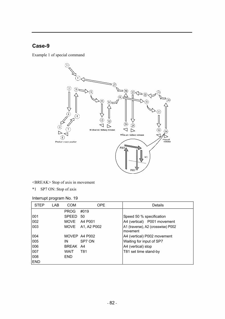
Case-9 Example 1 of special command
<BREAK> Stop of axis in movement *1 SP7 ON: Stop of axis
Interrupt program No. 19 STEP LAB COM OPE Details
PROG #019 001 SPEED 50 Speed 50 % specification 002 MOVE A4 P001 A4 (vertical) P001 movement 003 MOVE A1, A2 P002 A1 (traverse), A2 (crosswise) P002
movement 004 MOVEP A4 P002 A4 (vertical) P002 movement 005 IN SP7 ON Waiting for input of SP7 006 BREAK A4 A4 (vertical) stop 007 WAIT T81 T81 set time stand-by 008 END END

- 83 -
Example 2 of special command
<PAUSE> Step suspension *2 SP7 ON: Suspension of axis *3 SP7 OFF: Release of suspension of axis
Interrupt program No. 19 STEP LAB COM OPE Details
PROG #019 001 SPEED 50 Speed 50 % specification 002 MOVE A4 P001 A4 (vertical) P001 movement 003 ON #251 Start of suspension program 004 MOVE A1, A2 P002 A1 (traverse) A2 (crosswise) P002 movement005 MOVE A4 P002 A4 (vertical) P002 movement 006 WAIT 1 1 second stand-by 007 OFF #251 Release of suspension program 008 END END

- 84 -
Suspension program No. 251 STEP LAB COM OPE Details
PROG #251 001 L100 IF SP7 OFF GOTO L001 Branch to L001 in the case of SP7 OFF 002 IF SP7 ON GOTO L002 Branch to L002 in the case of SP7 ON 003 L001 PAUSE OFF Release of step suspension 004 ALM 0 Release of alarm 005 OUT BZ OFF Release of buzzer 006 GOTO L100 007 L002 PAUSE ON Step suspension 008 ALM 1 NC alarm 1 output 009 OUT BZ ON Buzzer output 010 GOTO L100 011 END END

- 85 -
― APPENDIX ―
NC step check sheet
STEP LAB COM OPE Remarks

- 86 -
NC point check sheet
Point No.
Point name
A1 A2 A3 A4 A5 A6 A7 A8 Remarks

- 87 -
― APPENDIX ―
I/O connection circuit diagram PCN-1H20 Connector list
Toyo Giken PCN-1H20
Connector name
Manufacturer (type)
Product name
Model Quantity
- Hirose Denki Socket HIF3BA-20D-2.54 1 HIF3BA series Terminal HIF3-2226SC 20

- 88 -
OPM401 layout diagram inside the board
Details of connector
Symbol Name CON1 Board power supply (DC24V) CON2 Communication connector CONA Communication connector (for option) CONB Communication connector (for option) CONC Communication connector (for option) COND Communication connector (for option)
Details of LED display
Symbol Name State LED1 Board communication monitor Lights up in case of error (red)
Details of HIC input and output LED (COND)
Symbol Side A Side B HIC 3 Output 16 O16 (2B) Output 17 O17 (2A) HIC 4 Output 14 O14 (3B) Output 15 O15 (3A) HIC 5 Output 12 O12 (4B) Output 13 O13 (4A) HIC 6 Output 10 O10 (5B) Output 11 O11 (5A) HIC 7 Input 17 I17 (6A) Input 16 I16 (6B) HIC 8 Input 15 I15 (7A) Input 14 I14 (7B) HIC 9 Input 13 I13 (8A) Input 12 I12 (8B) HIC10 Input 11 I11 (9A) Input 10 I10 (9B)

- 89 -
·Connector
Connector name
Manufacturer (type)
Product name
Model Quantity
CON1 Nihon Crimp-style Terminal
VH connector VHR-2N 1
VH connector Contact SVH-21T-P1.1 2 CON2 Hirose Denki Protector DF1-5A-1.05 1
DF1 series Socket DF1-5S-2.5R26 1 CONA Interface board 1
SIOF88 CONB Interface board 1
SIOF88 CONC Interface board 1
SIOF88 COND Hirose Denki Socket HIF3BA-20D-2.54 1
HIF3BA series Terminal HIF3-2226SC 20

- 90 -
SIOF88 layout diagram inside the board
Details of connector
Symbol Name Details CNA Communication connector Board plug side connector CNB Communication connector External input and output connector
Details of HIC input and output LED
(Check them on the separate sheet because they vary according to the connectors to which they are
inserted.)
Symbol Side A Side B HIC 1 OUT ** (2B) OUT ** (2A) HIC 2 OUT ** (3B) OUT ** (3A) HIC 3 OUT ** (4B) OUT ** (4A) HIC 4 OUT ** (5B) OUT ** (5A) HIC 5 IN ** (6A) IN ** (6B) HIC 6 IN ** (7A) IN ** (7B) HIC 7 IN ** (8A) IN ** (8B) HIC 8 IN ** (9A) IN ** (9B)
Connector
Connector name
Manufacturer (type)
Product name
Model Quantity
Hirose Denki Socket HIF3BA-20D-2.54 1 CNB HIF3BA series Terminal HIF3-2226SC 20

- 91 -
Parts list Code No. Name Type Manufacture Qty Compatible
models Remarks
200127 Communication board
unit UNCM (360) Star Seiki 1
151264 Additional unit PI-B (360SK) Star Seiki 1
P.C. board and sheet metal are contained.
151265 Additional unit PI-C (360SK) Star Seiki 1
P.C. board and sheet metal are contained.
140124 Additional unit OPM-D (470SK) Star Seiki 1
P.C. board and BOX are contained.
140125 Additional unit OPM-C (470SK) Star Seiki 1
GX-500(S)Ⅲ GX-700(S)Ⅲ GX-1100(S)Ⅲ
P.C. board is contained.
151266 Additional unit PI-B (360LK) Star Seiki 1
P.C. board and sheet metal are contained.
151267 Additional unit PI-C (360LK) Star Seiki 1
P.C. board and sheet metal are contained.
140126 Additional unit OPM-D (470LK) Star Seiki 1
P.C. board and BOX are contained.
140127 Additional unit OPM-C (470LK) Star Seiki 1
GX-1500(S)Ⅲ GX-1800(S)Ⅲ
P.C. board is contained.
151123 Interlock P.C. board PI360 Star Seiki 1
350075 I/O
Interface P.C. board
SIOF88 Star Seiki 1
140062 Additional
I/O P.C. board
OPM401 Star Seiki 1
150772 Interface terminal
block PCN-1H20 Toyo Giken 1
140123 Carriage unit relay
board OTB470 Star Seiki 1

- 92 -
PI-B,PI-C (360SK) Layout diagram for GX-500(S)III, 700(S)III
PI-C
(360
SK
) P
I-B (3
60S
K)
- 93 -
PI-B, PI-C (360SK) Layout diagram for GX-1100(S)III
PI-C
(360
SK
) P
I-B (3
60S
K)

- 94 -
OPM-D (470SK) Layout diagram

- 95 -
OPM-C (470SK) Layout diagram
- 96 -
PI-B, PI-C (360LK) Layout diagram for GX-1500(S)III, 1800(S)III
PI-B (360LK)
PI-C (360LK)

- 97 -
OPM-D (470LK) Layout diagram

- 98 -
OPM-C (470LK) Layout diagram

- 99 -
PI360 board additional guidance

- 100 -
OTB470 board additional guidance

- 101 -
PI-B additional I/O additional circuit diagram

- 102 -
PI-C additional I/O additional circuit diagram

- 103 -
OPM-D additional I/O additional circuit diagram

- 104 -
OPM-C additional I/O additional circuit diagram

00-A
0 6 0 1 - 0 2 - A
RECYCLED PAPER USED