marani lpp-360a user manualmarani lpp-360a user manual described below are the functions of the...
TRANSCRIPT

MARANI LPP-360A User Manual Described below are the functions of the front panel control buttons and encoders for the LPP-
360A.
• Getting Started
As soon as the LPP-360A is turned ON the device model name will appear in the LCD screen:
and a status bar will show the progress of the LPP-360A initialization process:
After the first time activation, the LPP-360A will show on the LCD :
LPP-360A SPEAKER PROCESSOR
LPP-360A
LPP-360A P01: Default

• Encoders and ENTER, ESC buttons
The LPP-360A is equipped with 3 Relative Encoders, “PM1”, “PM2” and “PM3”, These encoders
allow you to navigate the user interface and edit sections of the processor. They allow the user
to navigate within the screen for the selection of sub-menus, pages and parameters and to select
the values to be assigned during the editing operations.
The “ENTER” and “ESC” buttons allow the user to confirm or NOT confirm the operations
performed by the encoders.
• UTILITY, A/B/C and 1/2/3/4/5/6 buttons
The UTILITY button allows the User to enter the Sub-menus and set the general characteristics of
the Processor. The A , B , C buttons allow the User to enter the Editing Menus of the Processor's
Input Channels and buttons 1, 2, 3 , 4, 5, 6 allow the User to enter the Editing Menus of the
Processor's Output Channels.
The A , B , C buttons as well as the 1, 2, 3 , 4, 5, 6 buttons have double functions dependent on
the push and hold time.
When the A , B , C buttons are pushed and held for more than one second Input Channels A or B
or C are either muted or unmuted. The red LED will illuminate when the Channel is muted.
When the “MUTE” LED is OFF, then the related Input Channel is UN-MUTED.
A momentary push of the A , B , C buttons enters the Editing Mode for the Input Channels (see
later for the Input Channel Editing details).
The blue “EDIT” LED will now be ON.
When the 1, 2, 3 , 4, 5, 6 buttons are pushed and held for more than one second the Output
Channels 1, 2, 3 , 4, 5, 6 are either muted or unmuted. The red LED will illuminate when the
Channel is muted. When the “MUTE” LED is OFF, then the related Output Channel is UN-MUTED.
A momentary push of the 1, 2, 3 , 4, 5, 6 buttons enters the Editing Menu for the Output
Channels (see later for the Output Channel Editing details). The blue “EDIT” LED will now be ON.
• LPP-360A Menu and Sub-Menu Structures
As stated above, the start-up default screen is the following factory preset:
From this point, sub-menus are accessed and exited using the UTILITY”, “A/B/C”, “1/2/3/4/5/6”,
“ENTER” and “ESC” buttons and all parameters and values are navigated by the “PM1”, “PM2” and
“PM3” encoders. Please refer to the following menu structures:
LPP-360A P01: Default

MENU “UTILITY MENU” [Access by pushing the “UTILITY” button]
PM1 Encoder PM2 or PM3 Encoder
[to navigate between menus] [to chose option, then ENTER to load it; (*) indicates the selected option]
1 UTILITY MENU:......
<< System Utilities >>
1.1 SYSTEM UTILITY: Input Source << Input Source >> Source = Analog input
Source =Digital Input
Source = Noise Gen
1.2 SYSTEM UTILITY: Noise Generator << Noise Generator >> Type = Pink
Type = White
Lev = 0dB
: Lev:-40Db
1.3 SYSTEM UTILITY: Delay Units
<< Delay Units >> Unit = Time(ms) Unit = Distance (m)
1.4 SYSTEM UTILITY: Set Default Value
<< Set Default Value >> [Enter] to confirm
1.5 SYSTEM UTILITY: Firmware Version
<< Firmware Version >> Version = 3.1.9
2 UTILITY MENU:......
<< Program Utilities >>
2.1 PROGRAM UTILITY: Recall a Program
<< Recall a Program >> 01 Empty Program : :
16 Empty Program
2.2 PROGRAM UTILITY: Save a Program
<< Save a Program >> 01: Empty Program : :
16: Empty Program
2.3 PROGRAM UTILITY: Delete a Program << Delete a Program >> 01: Empty Program
: :
16: Empty Program
3 UTILITY MENU:......
<< Interface Utilities >>
3.1 INTERFACE UTILITY: Interface Setup
Interface Setup Source = USB
Source = RS485 ID=1,…,32
Source = TCP/IP DHCP=On/Off Set IP address IP=192.168.000.01-- 254
4 UTILITY MENU:...... << Security Utilities >>
4.1 SECURITY UTILITY: Parameter will
Show Parameter be shown
not be shown
4.2 SECURITY UTILITY: Lock Unit Lock Unit Lock: Off
Lock: On
4.3 SECURITY UTILITY: Change Password Change Password [ ]
4.4 SECURITY UTILITY: Enter Password Lock With Password [ ]
ENTER ESC
ENTER ESC
ENTER ESC
ENTER ESC
ENTER
ESC
ENTER
ESC
ENTER
ESC
ENTER
ESC
ENTER
ESC
ENTER
ESC
ENTER
ESC
ENTER
ESC
ENTER
ESC
ENTER
ESC
ENTER
ESC
ENTER
ESC
ENTER
ESC

MENU “Input A/B/C” Input Channels Editing [Access by pushing the “A/B/C” button] PM1 Encoder PM1 Enc. PM2 Enc. PM3 Enc.
[to navigate between menus] [to chose values for the parameters, no need to confirm the chosen values,
which are automatically loaded during the encoders use]
1. In- A/B/C [Name] Name
Name = [Name]
-> Name = _ (For Editing the Device's Name, refer to the Details on the“Utility Menus Use” Section)
2. In- A/B/C [Name] N.Gate
Bypass=On
-> Bypass=On PM1 N/A. Byp=On/Off Thr=-80.0dBu … -50 dBu
Rel=10ms … 1000ms Atk=1ms … 1000ms
3. In- A/B/C Gain Gain = + 0.0 dB
-> Gain = + 0.0 dB PM1 N/A. -18 dB 0.1dB
: :
+12dB 0.9dB
Step 1dB Step 0.1dB
4. In- A/B/C Delay
Delay = 0.000 ms
-> Delay = 0.000 ms PM1 N/A. 000.0000mS 000.0000mS
[1 ms steps] [10.4 us steps] 480.0000mS 000.9984mS
5 In- A/B/C [Name] Phase Phase=Normal
-> Phase=Normal PM1 N/A. Phase= Normal/Invert
6. In- A/B/C [Name] RMS Cmp
Bypass=On
-> Bypass=On PM1 N/A. Byp=On/Off
PM1 N/A. Threshold=+20dBu … -10dBu
PM1 N/A. Ratio =2:1 … 32:1 Knee=0% … 100%
PM1 N/A. Rel=1ms … 10.sec Atk=0.1ms … 5000ms
PM1 N/A. Make-up=-12dB … +12dB
7. In- A/B/C [Name] EQ Byp
Bypass=On
-> Bypass=On PM1 N/A. Byp=On/Off
8. In- A/B/C [Name] PEQ-XX(00 to 13)
Byp=on Type=Peaking_Eq
-> Byp=on Type=Peaking_Eq PM1 N/A. Byp=On/Off Type=Peaking_Eq/ Hi Shelv
1/ Hi Shelv 2/ Hi Shelv Q/ Lo Shelv 1/ Lo Shelv 2/Lo Shelv Q/ Low Pass 1/ Low-Pass 2/Low Pass Q/HighPass1/ HighPass2/ HighPassQ/Band-Pass/ Notch Filt/All Pass
1/All Pass 2
Type=Peaking_Eq PM1 N/A. Frequency=20Hz … 20000Hz
PM1 N/A. Gain=-15dB … +15dB Q=0.4 … 128
Type= Hi -Shelv 1/ Hi -Shelv 2 PM1 N/A. Frequency=20Hz … 20000Hz
ENTER ESC
ENTER ESC
ENTER ESC
ENTER ESC
ENTER ESC
ENTER ESC
ENTER ESC
ENTER ESC

PM1 N/A. Gain=-15dB … +15dB Q=Fixed
Type= Hi -Shelv Q PM1 N/A. Frequency=20Hz … 20000Hz
PM1 N/A. Gain=-15dB … +15dB Q=0.1 … 5.1
Type= Lo-Shelv 1/ Lo-Shelv 2 PM1 N/A. Frequency=20Hz … 20000Hz
PM1 N/A. Gain=-15dB … +15dB Q=Fixed
Type= Lo-Shelv Q PM1 N/A. Frequency=20Hz … 20000Hz
PM N/A. Gain=-15dB … +15dB Q=0.1 … 5.1
Type= Low Pass 1/ Low Pass 2 PM1 N/A. Frequency=20Hz … 20000Hz
Type= Low Pass Q PM1 N/A. Frequency=20Hz … 20000Hz
PM1 N/A. Gain=-Fixed Q=0.1 … 5.1
Type= Hi ghPass1/ Hi ghPass2 PM1 N/A. Frequency=20Hz … 20000Hz
Type= Hi ghPass Q PM1 N/A. Frequency=20Hz … 20000Hz
PM1 N/A. Gain=-Fixed Q=0.1 … 5.1
Type= Band-Pass PM1 N/A. Frequency=20Hz … 20000Hz
PM1 N/A. Gain=-15dB … +15dB Q=4 … 104
Type= Notch Filt PM1 N/A. Frequency=20Hz … 20000Hz
PM1 N/A. Gain=Fixed Q=4 … 104
Type= All Pass 1 PM1 N/A. Frequency=20Hz … 20000Hz
Type= All Pass 2 PM1 N/A. Frequency=20Hz … 20000Hz
PM1 N/A. Gain=Fixed Q=4 … 104

MENU “Output 1/2/3/4/5/6” Output Channels Editing [Access by pushing the “1/2/3/4/5/6” button]
PM1 Encoder PM1 Enc. PM2 Enc. PM3 Enc.
[to navigate between menus] [to chose values for the parameters, no need to confirm the chosen values,
which are automatically loaded during the encoders use]
1. Output[x] [Name] Name
Name = [Name]
-> Name = _ (For Editing the Device's Name, refer to the Details on the“Utility Menus Use” Section)
2. Output[x] [Name] Routing
A=On B=Off C=Off D=Off
-> InA: Level=0dB On PM1 N/A 0 dB On/Off
:
-30dB
-> InB: Level=0dB on PM1 N/A 0 dB On/Off
:
-30dB
-> InC: Level=0dB On PM1 N/A 0 dB On/Off
:
-30Db
-> InD: Level=0dB On PM1 N/A 0 dB On/Off
:
-30Db
3. Output[x] [Name] Gain Gain = + 0.0 dB
-> Gain = + 0.0 dB PM1 N/A -18 dB 0.1dB
: :
+12dB 0.9dB
Step 1dB Step 0.1dB
4. Output[x] [Name] Delay
Delay = 0.000 ms
-> Delay = 0.000 ms PM1 N/A 000.0000mS 000.0000mS
[1 ms steps] [10.4 us steps]
340.0000mS 000.9984Ms
5. Output[x] [Name] Phase
Phase=Normal
-> Phase=Normal PM1 N/A. Phase= Normal/Invert
6. Output[x] [Name] RMS Cmp
Bypass=On
-> Bypass=On PM1 N/A. Byp=On/Off
PM1 N/A. Threshold=+20dBu … -10dBu
PM1 N/A. Ratio =2:1 … 32:1 Knee=0% … 100%
PM1N/A. Rel=1ms… 10s Atk=0.1 … 5000ms
PM1 N/A. Make-up=-12dB … +12dB
7. Output[x] [Name] Limiter
Bypass=On
-> Bypass=On PM1 N/A. Bypass= On/Off
PM1 N/A. Threshold=-10dBu … 20 dBu
PM1 N/A. Rel=0.04sec … 6.0sec Atk=0.1ms … 900ms
8. Output[x] [Name] HPF
20.0 Hz Bypass
ENTER ESC
ENTER ESC
ENTER ESC
ENTER ESC
ENTER ESC
ENTER ESC
ENTER ESC
ENTER ESC

-> 20.0 Hz Bypass PM1 N/A [Freq.] 20Hz [Type/Slope] Bypass
: :
20kHz LR -48 dB /Oct
Slope=Bypass/ BW -6 dB/Oct / BW -12 dB/Oct / LR -12 dB/Oct / BS -12 dB/Oct / BW -18 dB/Oct / BW -24 dB/Oct / LR -24 dB/Oct / BS -24
dB/Oct / BW -36 dB/Oct / LR-36 dB/Oct / BW -48 dB/Oct / LR-48 dB/Oct /
9. Output[x] [Name] LPF
20.0 Hz Bypass
-> 20.0 Hz Bypass PM1 N/A [Freq.] 20Hz [Type/Slope] Bypass
: :
20kHz LR -48dB/Oct
Slope=Bypass/ BW -6 dB/Oct / BW -12 dB/Oct / LR -12 dB/Oct / BS -12 dB/Oct / BW -18 dB/Oct / BW -24 dB/Oct / LR -24 dB/Oct / BS -24
dB/Oct / BW -36 dB/Oct / LR-36 dB/Oct / BW -48 dB/Oct / LR-48 dB/Oct /
10. Output[x] [Name] EQ Byp
Bypass=On
-> Bypass=On PM1 N/A. Byp=On/Off
11. Output[x] [Name] PEQ-XX(00 to 11)
Byp=on Type=Peaking_Eq
-> Byp=on Type=Peaking_Eq PAR1 N/A. Byp=On/Off Type=Peaking_Eq/ Hi -Shelv
1/ Hi -Shelv 2/ Hi -Shelv Q/ Lo-Shelv 1/ Lo-Shelv 2/Lo-Shelv Q/ Low-Pass 1/ Low-Pass 2/Low-Pass Q/High-Pass1/ High-Pass2/High-Pass Q/Band-Pass/ Notch
Filt/All Pass 1/All Pass 2
Type=Peaking_Eq PM1 N/A. Frequency=20Hz … 20000Hz
PM1 N/A. Gain=-15dB … +15dB Q=0.4 … 128
Type= Hi -Shelv 1/ Hi -Shelv 2 PM1 N/A. Frequency=20Hz … 20000Hz
PM1 N/A. Gain=-15dB … +15dB Q=Fixed
Type= Hi -Shelv Q PM1 N/A. Frequency=20Hz … 20000Hz
PM1 N/A. Gain=-15dB … +15dB Q=0.1 … 5.1
Type= Lo-Shelv 1/ Lo-Shelv 2 PM1 N/A. Frequency=20Hz … 20000Hz
PM1 N/A. Gain=-15dB … +15dB Q=Fixed
Type= Lo-Shelv Q PM1 N/A. Frequency=20Hz … 20000Hz
PM1 N/A. Gain=-15dB … +15dB Q=0.1 … 5.1
Type= Low-Pass 1/ Low-Pass 2 PM1 N/A. Frequency=20Hz … 20000Hz
Type= Low-Pass Q PM1 N/A. Frequency=20Hz … 20000Hz
PM1 N/A. Gain=-Fixed Q=0.1 … 5.1
Type= High-Pass1/ High-Pass2 PM1 N/A. Frequency=20Hz … 20000Hz
Type= High-Pass Q PM1 N/A. Frequency=20Hz … 20000Hz
PM1 N/A. Gain=-Fixed Q=0.1 … 5.1
Type= Band-Pass PM1 N/A. Frequency=20Hz … 20000Hz
PM1 N/A. Gain=-15dB … +15dB Q=4 … 104
Type= Notch Filt PM1 N/A. Frequency=20Hz … 20000Hz
PM1 N/A. Gain=Fixed Q=4 … 104
Type= All Pass 1 PM1 N/A. Frequency=20Hz … 20000Hz
Type= All Pass 2 PM1 N/A. Frequency=20Hz … 20000Hz
PM1 N/A. Gain=Fixed Q=4 … 104
ENTER ESC
ENTER ESC
ENTER ESC

Menu “UTILITY” [access by pushing the “UTILITY” button]
From the “Default Screen”, it is possible access the “UTILITY” menu pushing the “UTILITY” button
and the Sub-Menus pages can be selected just rotating clockwise and counter-clockwise the
“PM1” encoder.
Once selected the sub-menu page, using the “ENTER” button can be accessed the Sub-Menus
pages, again “scrollable” using the “PM1” encoder and accessible for the parameters' editing
pushing again the “ENTER' button.
Note: In each sub-menu choice, the current selected or running choice is what shown on the LCD
screen.
System Utilities Sub-menu – this sub-menu allows to access several operations related to the
LPP-360A Start Up and General Configuration:
UTILITY MENU:
From the “System Utilities Sub-menu”, pushing “ENTER” and then using the “PM1” encoder for
scrolling will give access to the following pages:
Input Source: the LPP-360A is equipped with 4 Analog Inputs (Balanced Female XLR) and 2
AES Digital Input (RCA connector).and noise generator
The “Input Source” page allows you to select the desired Input type:
By pressing ENTER on Input Source and then rotating the “PM2” or “PM3” encoders, it is
possible to select the Main Inputs for the LPP-360A, allowing the User to choose between
Analog , AES Digital Input or Noise Generator.
The selection can be confirmed by pressing the “ENTER” button.
The following screen shows that the Analog Input has been selected:
UTILITY MENU -- System Utilities --
SYSTEM UTILITY -- Input Source --
Input Source Source = Analog input

UTILITY MENU:
Noise Generator: LPP-360A equips with 2 types of noise generator: White Noise and Pink
Noise.
By pressing ENTER and rotating the “PM2” encoder, it is possible to select between those 2
choice: “Pink” or “White”. By rotating the “PM3” encoder, it is possible to set the value of level
of white noise generator and pink noise generator, with whose range from 0dB to -40dB.
The following screen shows the selected pink noise with level of -20dB:
Delay Units: this page allows you to select the measurement unit to be used for the Delays:
Time (in milliseconds “ms”) or Distance (in meters “m”):
By pressing ENTER button and rotating the “PM2” or “PM3” encoder, it is possible to select the
measurement unit to be used for the delay, which will be confirmed by pushing the ENTER
button.
The following screen shows the selected delay measurement is Time (milliseconds)
Set Default Value: All setting for LPP-360A can be set to default value:
By pressing ENTER button, will show up the following screen of an interface to confirm to set
the default value:
By pressing ENTER button one more time, will show up the following screen:
SYSTEM UTILITY -- Delay Units --
Delay Units Unit : = Time (ms) *
SYSTEM UTILITY -- Noise Generator --
Noise Generator Type=Pink Lev=-20dB
SYSTEM UTILITY -- Set Default Value --
Set Default Value [Enter] to confirm

Wait around 3 sec for the processor set to the default value.
Firmware Version: this page allows you to confirm the Firmware Version running on the
LPP-360A:
The correct Firmware Version is “V3.1.9”
Program Utilities Sub-menu – this sub-menu allows you to access several options related to
the LPP-360A operating mode and to manage the presets stored and recallable within the Unit:
Recall a Program: this page allows the Loading of a preset program by pressing the “ENTER”
button. You can store up to 16 presets in the LPP-360A memory:
By pressing “ENTER” button and rotating the “PM1” encoders, it is possible to scroll through all
current available presets.
If NO USER PRESETS are stored yet, the screen will show the following:
If presets have previously been stored by the user, anyone of them can be recalled:
By using the “PM1” encoder it is possible to scroll through the stored presets. Once the
Recall a Program 01: Default
[ENTER] to Recall. 01: PRESET 1
PROGRAM UTILITY -- Recall a Program --
UTILITY MENU -- Program Utilities --
Set Default Value Wait : loading default….
SYSTEM UTILITY -- Firmware Version --
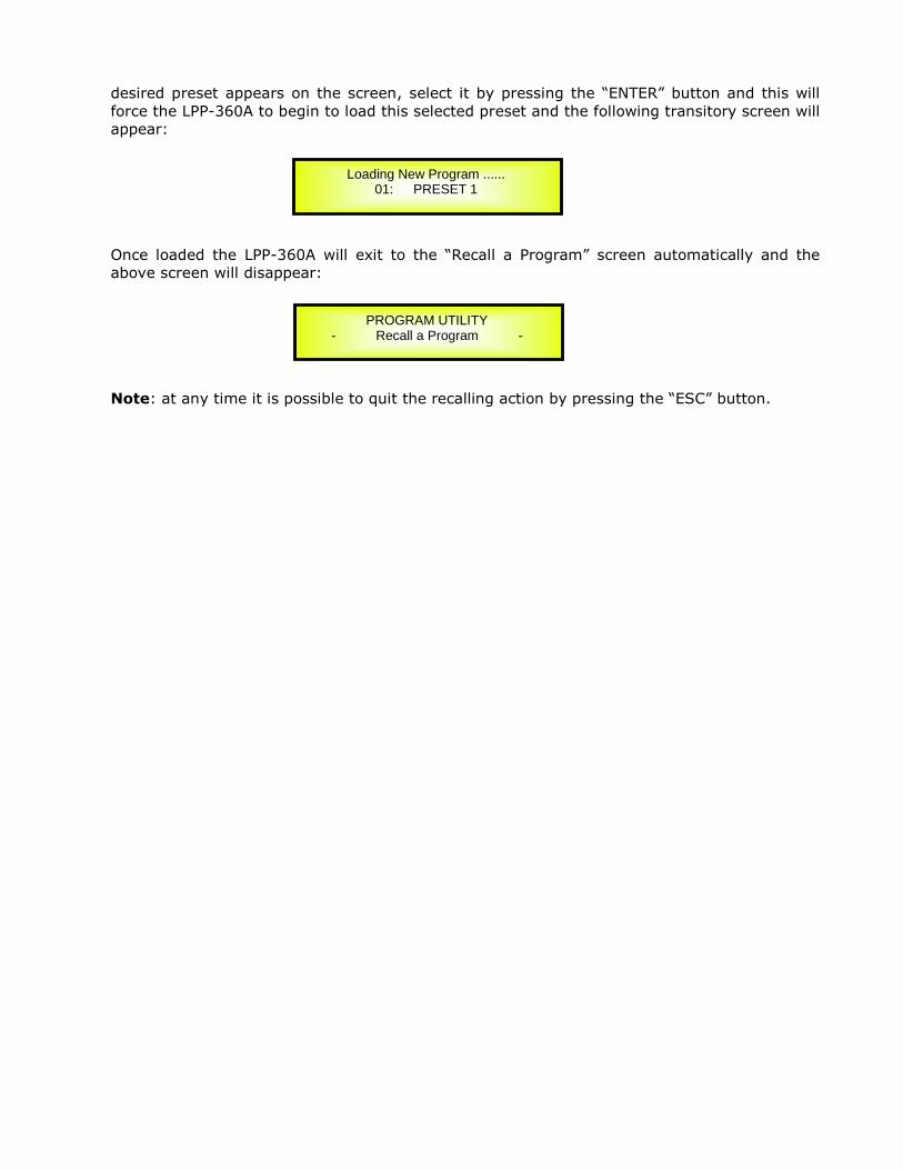
desired preset appears on the screen, select it by pressing the “ENTER” button and this will
force the LPP-360A to begin to load this selected preset and the following transitory screen will
appear:
Once loaded the LPP-360A will exit to the “Recall a Program” screen automatically and the
above screen will disappear:
Note: at any time it is possible to quit the recalling action by pressing the “ESC” button.
Loading New Program ...... 01: PRESET 1
PROGRAM UTILITY - Recall a Program -

Save a Program: this page allows you to store a new preset in the LPP-360A’s memory:
By pressing the ENTER button and rotating the “PM1” encoder, it is possible to scroll through
the previously saved presets or the available empty locations (identified by “Empty Program”).
If no user presets are stored, the “Save a Program” screen will show empty memory locations
for all 1-32 presets as shown in the example below for location 10:
When storing an edited configuration for the LPP-360A, select the location for a preset from
the 16 available by using the “PM1” encoders.
Once the desired location appears on the screen press “ENTER” button again to reach the “Set
Program Name” page.
In this page the User can set a Preset Name by using the “PM3” encoder to choose a character
and the “PM2” encoder to move between the available locations for the character’s positioning.
The following is an example of a screen while entering the preset name “Stage 1 2x2” in
location 10:
To store the Preset Name press the “ENTER” button again.
The above action will take you to the “Enter to Save” page showing the selected location for
the preset and the final edited name:
Pressing “ENTER” again, will store the preset in the selected location with the chosen name
and the following transitory screen will appear on the LCD:
Once the preset is stored, the above screen will disappear returning to the following screen:
Save a Program 10: Empty Memory
Set Program Name. 10: Stage 1 2x2
PROGRAM UTILITY -- Save a Program --
[Enter] to Save 10: Stage 1 2x2 ?
PROGRAM UTILITY -- Save a Program --
Saving to Memory..... 10: Stage 1 2x2

If during the Preset Storing process you want to overwrite an existing memory location select
this location in the “Save a Program” page, then press ENTER button and you will be asked if
you want to overwrite this preset with the following “[ENTER] to Overwrite” screen
displaying the currently stored preset and location:
If you wish to proceed press “ENTER” again and the LPP-360A will go ahead with the “Set
Program Name” page and the subsequent overwrite on completion of the previously
described storing process..
Note: at any time it is possible to quit the storing action by pressing the “ESC” button.
Delete a Program: this page allows you to delete a preset already stored in the LPP-360A
memory:
By pressing the ENTER button and rotating the “PM1” encoder, it is possible to scroll through
the previously saved presets and the available empty locations (identified by “Program
empty”).
If no user presets are stored, the “Delete a Program” screen will show empty memory
locations for all 1-16 presets as shown in the example below for location 10:
If Presets are available they will be shown in the “Delete a Program” page as follows:
By using the “PM1” encoder it is possible to select a preset to be deleted.
Pressing the “ENTER” button on a selected preset will bring up the “[Enter] to Delete.” page
showing the selected preset.
Delete a Program 10: Stage 1 2x2
[Enter] to Overwrite 10: Stage 1 2x2
PROGRAM UTILITY -- Delete a Program --
Delete a Program 10: Program empty

For example, if we want to delete the preset 10, “Stage 1 2x2”, the screen will be the
following:
Confirming the deletion by pressing “ENTER” again, will force the LPP-360A to erase the
selected preset and the following transitory screen will appear:
Once the preset is deleted, the above screen will disappear returning to the following screen:
Note: At any time it is possible to quit the deleting action by pressing the “ESC” button.
Interface Utilities Sub-menu – this sub-menu allows you to define the remote control interface
[USB, RS485 or TCP/IP] to be used for controlling the LPP-360A:
From “Interface Utilities”, press “ENTER” button to access the Interface Setup.
Interface Setup: this screen allows you to choose the communication source for the LPP-
360A.
If select RS485, connect more than one unit under the RS485 mode. By using “PM3” encoder,
user can set the ID number from 1 to 32, to assign to the units connected, and confirm by
pressing “ENTER” button.
If select TCP/IP, select the DHCP status by using “PM3” encoder, with choice of “ON” or “OFF”.
Interface Setup Source=USB
UTILITY MENU -- Interface Utilities --
PROGRAM UTILITY -- Delete a Program --
Erasing Xover Memory..... 10: Stage 1 2x2
[ENTER] to Delete. 10: Stage 1 2x2
Interface Setup Source=RS485 ID=01

The following screen displaying the currently selected interface as TCP/IP:
When you select TCP/IP, but the DHCP is “OFF”, by pushing “ENTER” button again to set the IP
address of the unit.
By rotating “PM3” encoder, user can select the IP value, and by scrolling “PM2” to move
between available space, user can edit the IP value postion.
If select TCP/IP, and the DHCP is “ON”, press “ENTER” button one more time, the unit will
notify that the DHCP is already activated, shown as the following screen display:
IP address of the unit need to get from the router connected to the network the unit already in.
Security Sub-menu – this sub-menu allows the User to set the parameters shown, lock the
LPP-360A and set a Password therefore limiting the unit's functions and controls to those who
have only access to the appropriate Password.
Press “ENTER” button and then use the “PM1” encoder to scroll between options.
Show Parameter: Pressing “ENTER” button from the above menu will access the “Show
Parameter” Sub Menu
Press ENTER button again and use the PM2 or PM3 encoders to select between “be shown” or
“not be shown” options.
Choosing the “be shown” option means that once the unit is locked, you cannot access
parameter editing features, but they will be displayed on the LCD screen.
Choosing the “not be shown” option means that once the unit is locked, the parameters will
not be shown at all. With this option, when trying to access a parameter, the following
screen message will appear:
UTILITY MENU -- Security Utilities --
SECURITY UTILITY -- Show Parameter --
Parameter will not be shown
Interface Setup Source=TCP/IP DHCP=On
Set IP address IP=192.168.000. 001
Interface Setup DHCP actived !

Lock Unit: this sub-menu allows the user to lock the device so no parameters can be edited
or modified.
When the Unit is in an unlocked condition, all parameters will be available for editing. When
you select On, all parameters will be locked and are not available for editing.
When you select lock from the menu, the unit will be locked and the lock menu automatically
exited. The screen will revert to the “Default” showing the current XOVER configuration and
the preset selected and beside the preset’s name a “keylock” icon indicating that the LPP-360A
is locked.
Change Password: from the “Change Password” sub-menu:
Press “ENTER” to access the “Change Password” page:
Use the PM2 encoder to move between available locations, and the PM3 encoder to choose a
character. The current position of the cursor for the characters to be entered is shown by a
“blinking underscore”.
Input the original password “000000” for the LPP-360A, and press “ENTER” button, will access
to the “New Password” Page. Use the PM2 encoder to move between available locations, and
rotate the PM3 encoder to edit a 6-position new password.
The following screen is the example with the new password after edition is “111111”
Change Password [_ ]
SECURITY UTILITY -- Lock Unit --
Lock Unit Lock = On
SECURITY UTILITY -- Change Password --
Change Password [ ]

Press the ENTER button again, will access the “Confirm password” page, use the “PM2”
encoder to move between available locations and rotate “PM3” encoder to choose a character,
input the new password edited just now.
The following screen is the example with typing in new password “111111” edited just now.
Press the ENTER button one more time, the new password will be set successfully.
Lock With Password: from the “Lock With Password” sub-menu:
There’s limitation to the editing function if the LPP-360A is locked with password. All functions for
this unit are banned, including MUTE A/B/C and MUTE 1/2/3/4/5/6 buttons.
Press “ENTER” to gain access to the “Enter Password” screen:
Use the “PM2” encoder to move between available locations, and rotate “PM3” encoder to select
characters. If the password of this LPP-360A never modified, input the default password “000000”,
the unit will be locked. In this case, default screen will show a “Key” icon, user cannot enter into
the sub-menu, unless he holds the password.
Confirm Password [111111]
SECURITY UTILITY -- Lock With Password --
Enter Password [ ]
New Password [111111]

Menu “Input A/B/C” Input Channels Editing [access by pushing the “A/B/C”
buttons]
From the “Default Screen”, it is possible to access the “Input A/B/C/D” menu by pushing the “A”
or “B” or “C” button. Once the button is pressed, the related blue “EDIT” LED will turn ON. The
Sub-Menu pages can now be scrolled through by rotating clockwise and counter-clockwise the
“PM1” encoder.
For parameter editing it is necessary to press “ENTER” button and an arrow will appear on the left
of the screen “->”. Then use the “PM2” and “PM3” encoders for editing and setting the
parameter values. On some parameters that have three independent values, you will also need to
use the PM1 encoder, eg filter parameter settings.
Note: All options can be done using the “PM1”, “PM2”, and “PM3” encoders and the current shown
value of the selected option is AUTOMATICALLY loaded during the encoders' use and stored as the
current value once leaving the page.
Remark 1: Select parameters the user desire by using 3 encoders. Once the user leaves this
page, the above mentioned parameters would be saved to the LPP-360A systems automatically.
Remark 2: Exit this page by pressing “ESC” button.
Audio Signal Input (A/B/C)
Name page – from this screen, it is possible to assign input channel a name with 6 characters
For example, name the Input A as “In L” in the Name Page:
By pressing ENTER in the Name page, user can edit the name, and there will be an arrow, as the
following screen shows:
The first character will flash.
Select character from these 6 positions by rotating “PM2” encoder and choose the desired
characters by rotating “PM3” encoder. Once the new name is defined, for example, “In A”, confirm
this new name by pressing ENTER… A new name will display on the screen, after replaced the old
one.
The following screen is shown with the new name “In A”, by replacing the previous one “In L”
N.Gate page– from this page, it is possible to set the Input Channels Noise Gate. Noise gate can
be set as “ON” or “OFF” status. The following screen is the selected “ON” status:
In-A In L Name Name = In L
In-A: In L Name ->Name = In L
In-A: In A Name Name = In A

By pressing ENTER button in this page, an arrow “->” will show up on the left of the screen, and
enter into the setting interface 1 of the noise gate:
By using the “PM2” encoder, it is possible to set the noise gate as “ON” or “OFF”. By using the
“PM3” encoder, it is possible to select its attack threshold from -80dBu to -50dBu.
By rotating “PM1” encoder, user can enter into the setting interface 2 of the noise gate:
By using “PM2” encoder, user can set noise gate release time: from 10ms to 1000ms, and using
“PM3” encoder to set noise gate attack time: from 1ms to 1000ms.
Gain page – from this screen it is possible to set the Input Channels Level from -18dB to +12dB,
press “ENTER” button, an arrow will appear on the left of the screen “->” then use the “PM2” or
“PM3” to set parameters.
The value set on this screen will only affect the input level of the selected Channel A.
The following is an example screen for the “Gain” page that has set the Gain of Input Channel A to
+0.0dB:
Delay page – from this page it is possible to set the Input Channels Delay Time from
000.0000mS up to 480.9984mS, by steps of 1mS or 10.4uS.
To set the Delay time press ENTER, an arrow will appear on the left of the screen “->”. then use
the “PM2” encoder to set the Delay Time in steps of 1mS and the “PM3” for setting the “fine”
Delay Time in steps of 10.4 microseconds.
The following is an example screen for the “Delay” page where the Delay Time of Input Channel A
is set to 160.1872mS:
Phase page– from this page, it is possible to set input channels phase as “Normal” or “Invert”.
The following is an example screen of “Normal” Phase:
In-A In-A N.Gate ->Byp=On Thr=-80.0dBu
In-A Name N.Gate Bypass = On
In-A In-A N.Gate ->Rel=10ms Atk=3ms
In-A In-A Gain -> Gain = + 0.0dB
In-A In-A Delay -> Delay = 160.1872mS

By pressing ENTER button in this page, an arrow will appear on the left of the screen “->”. then
use the “PM2” or “PM3” encoder for setting “Normal” or “Invert” Phase.
RMS Cmp page– from this page, it is possible to set RMS Compressor for input channels. RMS
Compressor can be set as “ON” or “OFF” status. The following is an example screen of “ON” status:
By pressing ENTER in this page, an arrow will appear on the left of the screen “->”. Then enter
into the setting interface 1 of RMS Compressor.
RMS compressor status can be set as “ON” or “OFF” by using “PM2” or “PM3” encoder.
By rotating “PM1” encoder, user can enter into setting interface 2 of RMS Compressor:
RMS Compressor attack threshold can be set with “PM2” or “PM3” encoder, with its range from
-10dBu to +20dBu.
By rotating “PM1” encoder one more time, user can enter setting interface 3 of RMS Compressor:
RMS Compressor ratio can be set by “PM2” encoder, with its range rom 2:1 ~ 32:1. RMS
Compressor knee can be set by “PM3” encoder, with its range from 0% ~ 100%.
By rotating “PM1” encoder once again, user can enter setting interface 4 of RMS Compressor:
RMS Compressor release time can be set by “PM2” encoder, with its selectable range from 0.1s ~
10s, and its attack time can be set by “PM3” encoder from 0.1ms ~ 5.0ms.
By rotating “PM1” encoder, user can enter setting interface 5 of RMS Compressor:
In-A In-A Phase Phase = Normal
In-A: In-A RMS Cmp Bypass = On
In-A In-A RMS Cmp ->Bypass = On
In-A In-A RMS Cmp ->Threshold = +20.0dBu
InputA: Name RMS Cmp ->Ratio =32:1 Knee =0%
In-A In-A RMS Cmp ->Rel =0.1sec Atk =0.1ms

By using “PM2” and “PM3” encoder, user can set RMS Compressor make up, from -12dBu to
+12dBu.
EQ Byp page – in this page, it is possible to set EQ Bypass of input channels, with its selectable
status of “ON” and “OFF”. Following is the example screen as Bypass ON:
By pressing “ENTER” button in this page, an arrow will appear on the left of the screen “->”, then
enter setting interface of EQ Bypass:
By using “PM2” or “PM3” encoder, user can set the EQ Bypass as “ON” or “OFF”.
PEQ-[xx] (01to13) page – In this page, it is possible to set 13 available parametric equalization
filters for input channels, with each parametric equalization filters can be selected as BELL,
Shevling, High-Pass, Low-Pass, Band-Pass, Notch filter and Allpass.
When EQ Bypass is set as “OFF”, by pressing ENTER in any parametric equalization page, an
arrow will appear on the left of the screen “->”, then enter setting interface 1 of parametric
equalization filter:
By using “PM2” encoder, it is possible to set the flat on or off for the current parametric
equalization filter. By using “PM3” encoder, user can set the current parametric equalization
filter’s type, selectable as Peaking_Eq/ Hi -Shelv 1/ Hi -Shelv 2/ Hi -Shelv Q/ Lo-Shelv 1/
Lo-Shelv 2/Lo-Shelv Q/ Low-Pass 1/ Low-Pass 2/Low-Pass Q/High-Pass1/ High-
Pass2/High-Pass Q/Band-Pass/ Notch Filt/ All Pass 1/ All Pass 2
When the parametric equalization filter is selected as Peaking Eq, by rotaing “PM1” encoder again,
user can enter the setting interface 2 of current input parametric equalization filter:
In-A In-A RMS Cmp ->Make-up = 0.0dB
In-A In-A EQ Byp Bypass = On
In-A In-A EQ Byp ->Bypass=On
In-A In-A PEQ-01 Byp=Off Type=Peaking_Eq
In-A In-A PEQ-01 ->Byp=Off Type=Peaking_Eq
In-A In-A PEQ-01 ->Frequency = 20Hz

By using “PM2” or “PM3” encoder, it is possible to set current input PEQ filter’s frequency from the
range of 20Hz to 20kHz.
By rotaing “PM1” encoder again, user can enter the setting interface 3 of current input parametric
equalization filter:
By using “PM2” encoder, user can set the gain of current parametric equalization filter from -15dB
to +15dB, and by using “PM3” encoder, it is possible to set the Q factor of current parametric
equalization filter from 0.4 to 128.
When the parametric equalization filter is selected as Hi-Shelv 1/ Hi-Shelv 2/ Lo-Shelv 1/ Lo-Shelv
2, by rotaing “PM1” encoder again, user can enter the setting interface 4 of current input
parametric equalization filter:
By using “PM2” or “PM3” encoder, it is possible to set current input PEQ filter’s frequency from the
range of 20Hz to 20kHz.
By rotaing “PM1” encoder again, user can enter the setting interface 5 of current input parametric
equalization filter:
By using “PM2” or “PM3” encoder, user can set the gain of current parametric equalization filter
from -15dB to +15dB.
When the parametric equalization filter is selected as Hi-Shelv Q/ Lo-Shelv Q, by rotaing “PM1”
encoder, user can enter the setting interface 6 of current input parametric equalization filter:
By using “PM2” or “PM3” encoder, it is possible to set current input PEQ filter’s frequency from the
range of 20Hz to 20kHz.
By rotaing “PM1” encoder again, user can enter the setting interface 7 of current input parametric
equalization filter:
In-A In-A PEQ-01 ->Gain=0.0dB Q=0.40
In-A In-A PEQ-01 ->Frequency = 20Hz
In-A In-A PEQ-01 ->Gain=0.0dB Q=Fixed
In-A In-A PEQ-01 ->Frequency = 20Hz
In-A In-A PEQ-01 ->Gain=0.0dB Q=0.1
By using “PM2” encoder, user can set the gain of current parametric equalization filter from -15dB
to +15dB, and by using “PM3” encoder, it is possible to set the Q factor of current parametric
equalization filter from 0.1 to 5.1.
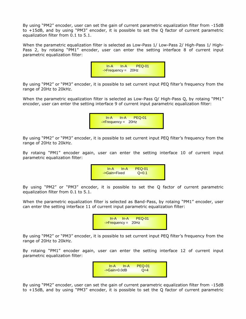
When the parametric equalization filter is selected as Low-Pass 1/ Low-Pass 2/ High-Pass 1/ High-
Pass 2, by rotaing “PM1” encoder, user can enter the setting interface 8 of current input
parametric equalization filter:
By using “PM2” or “PM3” encoder, it is possible to set current input PEQ filter’s frequency from the
range of 20Hz to 20kHz.
When the parametric equalization filter is selected as Low-Pass Q/ High-Pass Q, by rotaing “PM1”
encoder, user can enter the setting interface 9 of current input parametric equalization filter:
By using “PM2” or “PM3” encoder, it is possible to set current input PEQ filter’s frequency from the
range of 20Hz to 20kHz.
By rotaing “PM1” encoder again, user can enter the setting interface 10 of current input
parametric equalization filter:
By using “PM2” or “PM3” encoder, it is possible to set the Q factor of current parametric
equalization filter from 0.1 to 5.1.
When the parametric equalization filter is selected as Band-Pass, by rotaing “PM1” encoder, user
can enter the setting interface 11 of current input parametric equalization filter:
By using “PM2” or “PM3” encoder, it is possible to set current input PEQ filter’s frequency from the
range of 20Hz to 20kHz.
By rotaing “PM1” encoder again, user can enter the setting interface 12 of current input
parametric equalization filter:
By using “PM2” encoder, user can set the gain of current parametric equalization filter from -15dB
to +15dB, and by using “PM3” encoder, it is possible to set the Q factor of current parametric
In-A In-A PEQ-01 ->Frequency = 20Hz
In-A In-A PEQ-01 ->Frequency = 20Hz
In-A In-A PEQ-01 ->Gain=Fixed Q=0.1
In-A In-A PEQ-01 ->Frequency = 20Hz
In-A In-A PEQ-01 ->Gain=0.0dB Q=4

equalization filter from 4 to 104.
When the parametric equalization filter is selected as Notch Filt, by rotaing “PM1” encoder, user
can enter the setting interface 13 of current input parametric equalization filter:
By using “PM2” or “PM3” encoder, it is possible to set current input PEQ filter’s frequency from the
range of 20Hz to 20kHz.
By rotaing “PM1” encoder again, user can enter the setting interface 14 of current input
parametric equalization filter:
By using “PM2” or “PM3” encoder, it is possible to set the Q factor of current parametric
equalization filter from 4 to 104.
When the parametric equalization filter is selected as All Pass 1, by rotaing “PM1” encoder, user
can enter the setting interface 15 of current input parametric equalization filter:
By using “PM2” or “PM3” encoder, it is possible to set current input PEQ filter’s frequency from the
range of 20Hz to 20kHz.
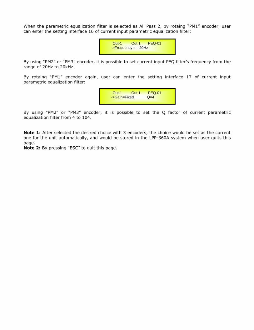
When the parametric equalization filter is selected as All Pass 2, by rotaing “PM1” encoder, user
can enter the setting interface 16 of current input parametric equalization filter:
By using “PM2” or “PM3” encoder, it is possible to set current input PEQ filter’s frequency from the
range of 20Hz to 20kHz.
By rotaing “PM1” encoder again, user can enter the setting interface 17 of current input
parametric equalization filter:
By using “PM2” or “PM3” encoder, it is possible to set the Q factor of current parametric
equalization filter from 4 to 104.
Note 1: If selected the desired options by using 3 encoders, the option would be set as a current
one for the unit automatically, and will be stored in the LPP-360A system when you exit the page.
Note 2: By pressing “ESC” button, you can exit the page any time.
In-A In-A PEQ-01 ->Frequency = 20Hz
In-A In-A PEQ-01 ->Gain=Fixed Q=4
In-A In-A PEQ-01 ->Frequency = 20Hz
In-A In-A PEQ-01 ->Frequency = 20Hz
In-A In-A PEQ-01 ->Gain=Fixed Q=4

Menu “Output 1/2/3/4/5/6” Output Channels Editing [access by pushing the
“1/2/3/4/5/6” buttons]
From the “Default Screen”, it is possible to access the “Output 1/2/3/4/5/6” menu by pressing the
“1” or “2” or “3” or “4” or “5” or “6” button. Once pressed, the related blue “EDIT” LED will turn
ON.
The Sub-Menus pages can now be scrolled through by rotating clockwise and counter-clockwise
the “PM1” encoder.
For parameter editing it is necessary to press ENTER and an arrow will appear on the left of the
screen “->”. Then use the “PM2” and “PM3” encoders for selecting and setting the parameter
values. On some parameters that have three independent values, you will also need to use the
PM1 encoder, for example for the filter’s parameter setting.
Note: All parameter editing can be done using the “PM1”, “PM2”, and “PM3” encoders and the
current shown value of the selected option is AUTOMATICALLY loaded during the encoders' use
and stored as the current value once leaving the page.
Audio Signal Output (1/2/3/4/5/6)
Name page – from this screen, it is possible to assign output channel a name with 6 characters
For example, name the Output 1 as “Low” in the Name Page:
By pressing ENTER in the Name page, user can edit the name, and there will be an arrow, as the
following screen shows:
The first character will flash.
Select character from these 6 positions by using “PM2” encoder and choose the desired characters
by rotating “PM3” encoder. Once the new name is defined, for example, “Sub”, confirm this new
name by pressing ENTER… A new name will display on the screen, after replaced the old one.
The following screen is shown with the new name “Sub”, by replacing the previous one “Low”
Routing page – in this page, it is possible to assign input “A/B/C” to any output channel:
Out-1 Out 1 Name Name = Low
Out-1 Out 1 Name -> Name = Low
Out-1 Out 1 Name Name = Sub
Out-1 Out 1 Routing A=0dB B=OFF C=OFF D=OFF

By pressing “ENTER” button, an arrow will appear on the left of the screen “->”. By using “PM1”
encoder, user can set the input value for INPUT A/B/C. By using the “PM2” encoder, user can
choose level of INPUT A to any output channel, from -30dB to 0dB. By using “PM3” encoder, user
can choose “ON” or “OFF” the INPUT A to any output channel.
Gain page – from this screen it is possible to set the Output Channels Level from -18dB to +12dB,
press “ENTER” button an arrow will appear on the left of the screen “->” then use the “PM2” or
“PM3” to set parameters.
The value set on this screen will only affect the output level of the selected Channel
1/2/3/4/5/6/7/8.
The following is an example screen for the “Gain” page that has set the Gain of Output Channel 1
to +0.0dB:
Delay page – from this page it is possible to set the Output Channels Delay Time from
000.0000mS up to 340.9984mS, by steps of 1mS or 10.4us.
To set the Delay time press “ENTER” button, an arrow will appear on the left of the screen “->”.
then use the “PM2” encoder to set the Delay Time in steps of 1mS and the “PM3” for setting the
“fine” Delay Time in steps of 10.4 microseconds.
The following is an example screen for the “Delay” page where the Delay Time of Output Channel
1 is set to 160.1872mS:
Phase page– from this page, it is possible to set output channels phase as “Normal” or “Invert”.
The following is an example screen of “Normal” Phase:
By pressing “ENTER” button in this page, an arrow will appear on the left of the screen “->”.
then use the “PM2” or “PM3” encoder for setting “Normal” or “Invert” Phase.
RMS Cmp page – from this page it is possible to set the Output Channels RMS Compressor.
RMS Compressor can be set as “ON” or “OFF”. The following is an example screen for the RMS
Compressor page where it is ON:
Out-1 Out 1 Gain -> Gain = + 0.0dB
Out-1 Out 1 Delay -> Delay = 160.1872mS
Out-1 Out 1 Phase Phase = Normal
Out-1 Out 1 RMS Cmp Bypass = On
Out-1 Out 1 Routing ->InA: Level=0dB On

By pressing ENTER in this page, an arrow will appear on the left of the screen “->”, then enter
into the setting interface 1 of RMS Comp:
By using “PM2” or “PM3” encoder, it is possible to set the RMS Comp as “ON” or “OFF”.
By rotating “PM1” encoder, will enter into the setting interface 2 of RMS Comp.
By using “PM2” and “PM3” encoder, user can set limiter attack threshold, with its range from -
10dBu to +20dBu.
By rotating “PM1” encoder again, it will enter setting interface 3 of RMS Comp.:
User can set RMS Cmp’s ratio by using “PM2” encoder from 2:1~32:1. With “PM3” encoder, it is
possible to set RMS Cmp’s knee from 0% ~ 100%.
By rotating “PM1” encoder, will enter into the setting interface 4 of RMS Comp.:
User can set RMS Cmp’s release time from 1ms to 10 sec by using “PM2” encoder, and set its
attack time by using “PM3” from 0.1ms to 5ms.
By rotating “PM1” encoder, will enter into the setting interface 5 of RMS Comp.:
By using “PM2” and “PM3” encoders, user can set the RMS Cmp’s make up from -12dBu to
+12dBu.
Limiter page – from this page it is possible to set the Output Channels Limiter. Limiter can be set
as “ON” or “OFF”. The following is an example screen for the Limiter page where it is ON:
Out-1 Out 1 RMS Cmp ->Bypass = On
Out-1 Out 1 RMS Cmp ->Threshold = +20.0dBu
Out-1 Out 1 RMS Cmp ->Ratio =32:1 Knee =0%
Out-1 Out 1 RMS Cmp ->Rel =1ms Atk =0.1ms
Out-1 Out 1 RMS Cmp ->Make-up = 0.0dB
Out-1 Out 1 Limiter Bypass = On

By pressing ENTER in this page, an arrow will appear on the left of the screen “->”, then enter
into the setting interface 1 of limiter:
By using “PM2” or “PM3” encoder, it is possible to set the limiter as “ON” or “OFF”.
By rotating “PM1” encoder, will enter into the setting interface 2 of limiter:
By using “PM2” and “PM3” encoder, user can set limiter attack threshold, with its range from -
10dBu to +20dBu.
By rotating “PM1” encoder again, it will enter setting interface 3 of limiter:
User can set limiter’s release time from 0.04 sec to 6 sec by using “PM2” encoder, and set its
attack time by using “PM3” from 0.1ms to 900ms.
HPF page – in this page, it is possible to set the High-Pass filter of output channels:
By pressing ENTER button in this page, an arrow will appear on the left of the screen “->”, then
enter into the setting interface 1 of High-Pass filter:
By using “PM2” or “PM3” encoder, it is possible to set output channels’ High-Pass filter frequency
from 20Hz to 20kHz.
By rotating “PM1” encoder, it will enter setting interface 2 of High-Pass filter:
By using “PM2” or “PM3” encoder, it is possible to set the High-Pass filter’s shape and order of the
output High-Pass filter. Following is the available shape and order of the High-Pass filter: Bypass/
Out-1 Out 1 HPF F= 20Hz Bypass
Out-1 Out 1 HPF ->Frequency = 20Hz
Out-1 Out 1 HPF ->Slope = Bypass
Out-1 Out 1 Limiter ->Bypass = On
Out-1 Out 1 Limiter ->Threshold = +20.0dBu
Out-1 Out 1 Limiter ->Rel =0.04sec Atk =0.3ms
BW -6 dB/Oct / BW -12 dB/Oct / LR -12 dB/Oct / BS -12 dB/Oct / BW -18 dB/Oct / BW -24
dB/Oct / LR -24 dB/Oct / BS -24 dB/Oct / BW -36 dB/Oct / LR-36 dB/Oct / BW -48 dB/Oct / LR-48 dB/Oct /
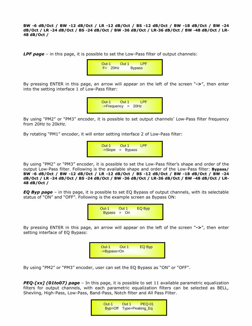
LPF page – in this page, it is possible to set the Low-Pass filter of output channels:
By pressing ENTER in this page, an arrow will appear on the left of the screen “->”, then enter
into the setting interface 1 of Low-Pass filter:
By using “PM2” or “PM3” encoder, it is possible to set output channels’ Low-Pass filter frequency
from 20Hz to 20kHz.
By rotating “PM1” encoder, it will enter setting interface 2 of Low-Pass filter:
By using “PM2” or “PM3” encoder, it is possible to set the Low-Pass filter’s shape and order of the
output Low-Pass filter. Following is the available shape and order of the Low-Pass filter: Bypass/
BW -6 dB/Oct / BW -12 dB/Oct / LR -12 dB/Oct / BS -12 dB/Oct / BW -18 dB/Oct / BW -24 dB/Oct / LR -24 dB/Oct / BS -24 dB/Oct / BW -36 dB/Oct / LR-36 dB/Oct / BW -48 dB/Oct / LR-
48 dB/Oct /
EQ Byp page – in this page, it is possible to set EQ Bypass of output channels, with its selectable
status of “ON” and “OFF”. Following is the example screen as Bypass ON:
By pressing ENTER in this page, an arrow will appear on the left of the screen “->”, then enter
setting interface of EQ Bypass:
By using “PM2” or “PM3” encoder, user can set the EQ Bypass as “ON” or “OFF”.
PEQ-[xx] (01to07) page – In this page, it is possible to set 11 available parametric equalization
filters for output channels, with each parametric equalization filters can be selected as BELL,
Shevling, High-Pass, Low-Pass, Band-Pass, Notch filter and All Pass Filter.
Out-1 Out 1 LPF F= 20Hz Bypass
Out-1 Out 1 LPF ->Frequency = 20Hz
Out-1 Out 1 LPF ->Slope = Bypass
Out-1 Out 1 EQ Byp Bypass = On
Out-1 Out 1 EQ Byp ->Bypass=On
Out-1 Out 1 PEQ-01 Byp=Off Type=Peaking_Eq

When EQ Bypass is set as “OFF”, by pressing ENTER button in any parametric equalization page,
an arrow will appear on the left of the screen “->”, then enter setting interface 1 of parametric
equalization filter:
By using “PM2” encoder, it is possible to set the flat on or off for the current parametric
equalization filter. By using “PM3” encoder, user can set the current parametric equalization
filter’s type, selectable as Peaking_Eq/ Hi -Shelv 1/ Hi -Shelv 2/ Hi -Shelv Q/ Lo-Shelv 1/ Lo-
Shelv 2/Lo-Shelv Q/ Low-Pass 1/ Low-Pass 2/Low-Pass Q/High-Pass1/ High-Pass2/High-Pass Q/Band-Pass/ Notch Filt/ All Pass 1/ All Pass 2
When the parametric equalization filter type is selected as Peaking_Eq, by rotaing “PM1” encoder
again, user can enter the setting interface 2 of current output parametric equalization filter:
By using “PM2” or “PM3” encoder, it is possible to set current output PEQ filter’s frequency from
the range of 20Hz to 20kHz.
By rotaing “PM1” encoder again, user can enter the setting interface 3 of current input parametric
equalization filter:
By using “PM2” encoder, user can set the gain of current parametric equalization filter from -15dB
to +15dB, and by using “PM3” encoder, it is possible to set the Q factor of current parametric
equalization filter from 0.4 to 128.
When the parametric equalization filter type is selected as Hi-Shelv 1/ Hi-Shelv 2/ Lo-Shelv 1/ Lo-
Shelv 2, by rotaing “PM1” encoder again, user can enter the setting interface 4 of current output
parametric equalization filter:
By using “PM2” or “PM3” encoder, it is possible to set current output PEQ filter’s frequency from
the range of 20Hz to 20kHz.
By rotaing “PM1” encoder again, user can enter the setting interface 5 of current input parametric
equalization filter:
Out-1 Out 1 PEQ-01 ->Byp=Off Type=Peaking_Eq
Out-1 Out 1 PEQ-01 ->Frequency = 20Hz
Out-1 Out 1 PEQ-01 ->Gain=0.0dB Q=0.40
Out-1 Out 1 PEQ-01 ->Frequency = 20Hz
Out-1 Out 1 PEQ-01 ->Gain=0.0dB Q=Fixed

By using “PM2” or “PM3” encoder, user can set the gain of current parametric equalization filter
from -15dB to +15dB.
When the parametric equalization filter type is selected as Hi-Shelv Q/ Lo-Shelv Q, by rotaing
“PM1” encoder again, user can enter the setting interface 6 of current output parametric
equalization filter:
By using “PM2” or “PM3” encoder, it is possible to set current output PEQ filter’s frequency from
the range of 20Hz to 20kHz.
By rotaing “PM1” encoder again, user can enter the setting interface 7 of current input parametric
equalization filter:
By using “PM2” encoder, user can set the gain of current parametric equalization filter from -15dB
to +15dB, and by using “PM3” encoder, it is possible to set the Q factor of current parametric
equalization filter from 0.1 to 5.1.
When the parametric equalization filter type is selected as Low-Pass 1/ Low-Pass 2/ High-Pass 1/
High-Pass 2, by rotaing “PM1” encoder again, user can enter the setting interface 8 of current
output parametric equalization filter:
By using “PM2” or “PM3” encoder, it is possible to set current output PEQ filter’s frequency from
the range of 20Hz to 20kHz.
When the parametric equalization filter type is selected as Low-Pass Q/ High-Pass Q, by rotaing
“PM1” encoder again, user can enter the setting interface 9 of current output parametric
equalization filter:
By using “PM2” or “PM3” encoder, it is possible to set current output PEQ filter’s frequency from
the range of 20Hz to 20kHz.
By rotaing “PM1” encoder again, user can enter the setting interface 10 of current input
parametric equalization filter:
Out-1 Out 1 PEQ-01 ->Frequency = 20Hz
Out-1 Out 1 PEQ-01 ->Gain=0.0dB Q=0.1
Out-1 Out 1 PEQ-01 ->Frequency = 20Hz
Out-1 Out 1 PEQ-01 ->Frequency = 20Hz
Out-1 Out 1 PEQ-01 ->Gain=Fixed Q=0.1
By using “PM2” or “PM3” encoder, it is possible to set the Q factor of current parametric
equalization filter from 0.1 to 5.1.
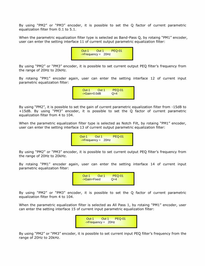
When the parametric equalization filter type is selected as Band-Pass Q, by rotaing “PM1” encoder,
user can enter the setting interface 11 of current output parametric equalization filter:
By using “PM2” or “PM3” encoder, it is possible to set current output PEQ filter’s frequency from
the range of 20Hz to 20kHz.
By rotaing “PM1” encoder again, user can enter the setting interface 12 of current input
parametric equalization filter:
By using “PM2”, it is possible to set the gain of current parametric equalization filter from -15dB to
+15dB. By using “PM3” encoder, it is possible to set the Q factor of current parametric
equalization filter from 4 to 104.
When the parametric equalization filter type is selected as Notch Filt, by rotaing “PM1” encoder,
user can enter the setting interface 13 of current output parametric equalization filter:
By using “PM2” or “PM3” encoder, it is possible to set current output PEQ filter’s frequency from
the range of 20Hz to 20kHz.
By rotaing “PM1” encoder again, user can enter the setting interface 14 of current input
parametric equalization filter:
By using “PM2” or “PM3” encoder, it is possible to set the Q factor of current parametric
equalization filter from 4 to 104.
When the parametric equalization filter is selected as All Pass 1, by rotaing “PM1” encoder, user
can enter the setting interface 15 of current input parametric equalization filter:
By using “PM2” or “PM3” encoder, it is possible to set current input PEQ filter’s frequency from the
range of 20Hz to 20kHz.
Out-1 Out 1 PEQ-01 ->Frequency = 20Hz
Out-1 Out 1 PEQ-01 ->Gain=0.0dB Q=4
Out-1 Out 1 PEQ-01 ->Frequency = 20Hz
Out-1 Out 1 PEQ-01 ->Gain=Fixed Q=4
Out-1 Out 1 PEQ-01 ->Frequency = 20Hz
When the parametric equalization filter is selected as All Pass 2, by rotaing “PM1” encoder, user
can enter the setting interface 16 of current input parametric equalization filter:
By using “PM2” or “PM3” encoder, it is possible to set current input PEQ filter’s frequency from the
range of 20Hz to 20kHz.
By rotaing “PM1” encoder again, user can enter the setting interface 17 of current input
parametric equalization filter:
By using “PM2” or “PM3” encoder, it is possible to set the Q factor of current parametric
equalization filter from 4 to 104.
Note 1: After selected the desired choice with 3 encoders, the choice would be set as the current
one for the unit automatically, and would be stored in the LPP-360A system when user quits this
page.
Note 2: By pressing “ESC” to quit this page.
Out-1 Out 1 PEQ-01 ->Frequency = 20Hz
Out-1 Out 1 PEQ-01 ->Gain=Fixed Q=4

Input and Output Channels Last Edited Parameter Return Function
Once you have escaped out of parameter editing within the individual Input or Output channels
the LPP-360A will remember this last editing action on that Channel. When you return for your
next editing action pressing the EDIT button on that channel will immediately return you to the
screen related to this last editing action.
This function makes fine tuning or modifying easier when it is necessary to make a number of
adjustments to the same parameter in a short time sequence.
Input Channels and output Channels LINK Function
The LPP-360A is able to perform a unique LINK MODE between Input Channels as well as a link
between Output Channels to enable quick and immediate editing (you cannot link output to input
channels).
To link channels when editing, you will need to select a “Master” channel that will be the one to be
edited and have it’s parameters displayed on the LCD screen. You can then select and link other
channels (Slaves) that you wish to apply the same changes to.
To enter a link mode session, select the Master channel Edit mode, then link the Slaves by
pressing their related Edit buttons.
All Linked channels will be selected ready for adjustment when their “Blue” LED is lit in the Editing
mode.
Now all Slave channels and only those selected will modify their parameters accordingly as you
edit the Master channel.
All other existing parameters will stay the same within the Slave Channels unless edited by this
link with the Master channel.
Note: The LINK function is NOT a COPY function.
If we want to edit the limiter of the Output channels 1/3/5, we can enter the editing mode of
Output Channel 1 by pressing the related Edit button and turning on the Blue LED below the
Output Channel 1 LED meters. This assigns the “role” of Master and displays this channel’s
parameters on the LCD:
Then press the Edit button of Output Channels 1/3/5, turning on their related “Blue” LED’s. Now
all parameters edited on Output Channel 1, will also be applied to channels 3 and 5.
If we want to remove one of the linked channels from the Link, press the related Edit button.
Exiting the editing of the Master channel during a Link session will automatically terminate that
session. The Link will also be automatically terminated if, during the editing of Output Channels
you jump across to begin editing an Input channel or vice versa.
Output1: Name Limiter ->Rel =1:1sec Atk =3ms
Factory Reset
In the event of the password being lost or any other reason the user may require the unit to be
reset to the original factory settings, a "Factory Reset" that will clear all settings of the LPP-360A
and return the device to the original factory setting, is available to the user.
Note: Continuing with this process will mean the LPP-360A will re-initialize to the original factory
settings and any previously stored information and changed parameters will be permanently lost.
Use the following procedure to perform the factory reset:
1. While the LPP-360A is switched OFF, simultaneously press the ENTER+ESC+UTILITY
buttons on the front panel.
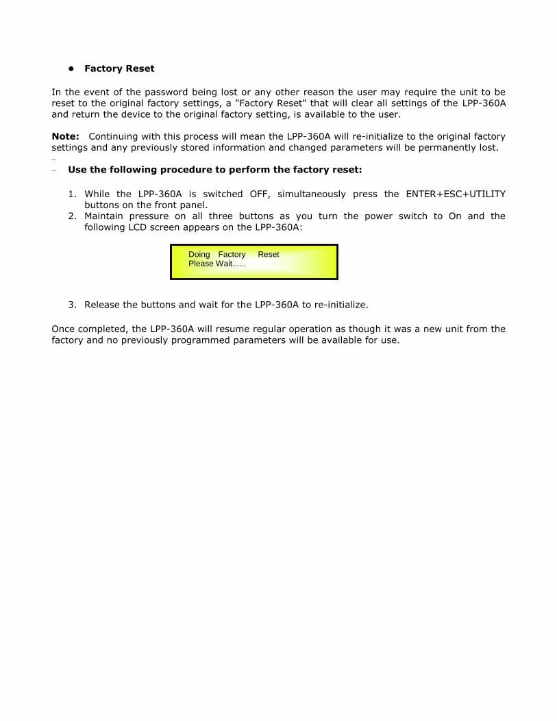
2. Maintain pressure on all three buttons as you turn the power switch to On and the
following LCD screen appears on the LPP-360A:
3. Release the buttons and wait for the LPP-360A to re-initialize.
Once completed, the LPP-360A will resume regular operation as though it was a new unit from the
factory and no previously programmed parameters will be available for use.
Doing Factory Reset Please Wait......

Guidence of Connecting LPP-360A with Unit through TCP/IP
Connection Premier Condition:
1. LPP-360A and PC already installed the LPP-360A PC software
2. Finished product of reticle, follow standard of 568A or 568B, suggest use 568B.
Note: This unit has 3 choice to connect to the PC: USB, RS485 and TCP/IP. The default of LPP-
360A is USB connection.
Connection Procedure:
1. Set the way of connecting LPP-360A and PC.
1.1 Power on LPP-360A, wait its LCD display as the following.
Click the “UTILITY” button, showing the first class content of the primary menue; please refer to
the following picture:
Rotate “NAV/PM1” encoder to change the primary menue as the following content:
1.2 push ”ENTER” button, LCD shows as the below display, reflecting the way how unit is
connected with computer
Rotate “PM2” and “PM3” encoder to change the interface as to the following display:
push “ENTER” button to show the current IP address of LPP-360A, as the following display:
LPP-360A P01: Default
UTILITY MENU:
--Interface Utilities--
UTILITY MENU
-- System Utilities --
Interface Setup
Source=USB
Interface Setup
Source=TCP/IP DHCP=Off
Set IP address IP=192.168.000.100

Rotate “PM2” encoder to edit the IP value. By using “PM3” encoder can change the IP address for
this unit.
NOTE: Only when DHCP is off can user set the IP address of the unit. If DHCP is ON, need to push
the “ENTER” button until the unit notify that the DHCP is activated, that the IP address of LPP-
360A need to capture from the router in its connected network.
2. Set the connection condition of PC (take XP for example)
Enter the PC’s “controlling Pannel’ ”network connect” ”local”, open the dialogue box of
“ Properties”, please refer to the following picture:
Select “Internet Protocol (TCP/IP” in “use the following subjects under this connection(0) ”, and
click the attribute bottom, marked in the red envelop in below image:
Open the dialogue box of “Internet aggreement (TCP/IP) attribute” and set as the following Fig 1,

Fig 1
3. Connect LPP-360A with computer
Power on LPP-360A, use reticle to conect LPP-360A with PC. Initiate the PC software, set
“communication port’’ to “TCP/IP” in the dialougue box. Then set “connection “to “with one device”
(if there are more than one units, set it as” with more devices”.)
Later set the “IP address” display the set PC IP: “Host Address: 192.168.0.2”. Set the “IP device”
same as the IP address of the LPP-360A. Note that in the example, the IP address of LPP-360A is
set as 192.168.0.100, so the “IP address” shall be set as 192.168.0.100, ,please refer to the
following picture:
Click the in the above image, will show the following interface, which means that the
LPP-360A already connected to the PC via reticle, the connection between this unit and the PC by
TCP/IP completes.


LPP-360A Technical Specifications
The LPP-360A is based on a powerful analog and digital DSP platform having the following
specifications
Analog Input Signal: ChA/ChB/ChC Bal. Female XLR
Maximum Input Level: +20dBu
Analog Output Signal: Ch1/Ch2/Ch3/Ch4/Ch5/Ch6 Bal. Male XLR
Maximum Output Level: +20dBu
Sampling Frequency: 96kHz
FIR Sampling Frequency: 48kHz
S/N: 110dBA
THD+N: 0.005%
Frequency Response (Bypass): 20Hz – 20kHz (+- 1 dB)
Power Supply: Switching Power Supply
Remote Control: USB, RS485, TCP/IP