control and data acquisition for fusion experiments€¦ · b. carvalho | eiroforum school on...
TRANSCRIPT

Instituto de Plasmas e Fusão Nuclear Instituto Superior Técnico Lisbon, Portugal http://www.ipfn.ist.utl.pt
B. Carvalho | EIROforum School on Instrumentation, ESI 2011 | Grenoble
Control and Data Acquisition for Fusion experiments
Bernardo Brotas Carvalho [email protected]

Film by Jean-Luc Godard, (1967) “2 ou 3 choses que je sais d'elle”

“The stakes are considerable, not to say vital for our planet.“ José Manuel Barroso, President of the European Commission
Fusion – a Global Challenge
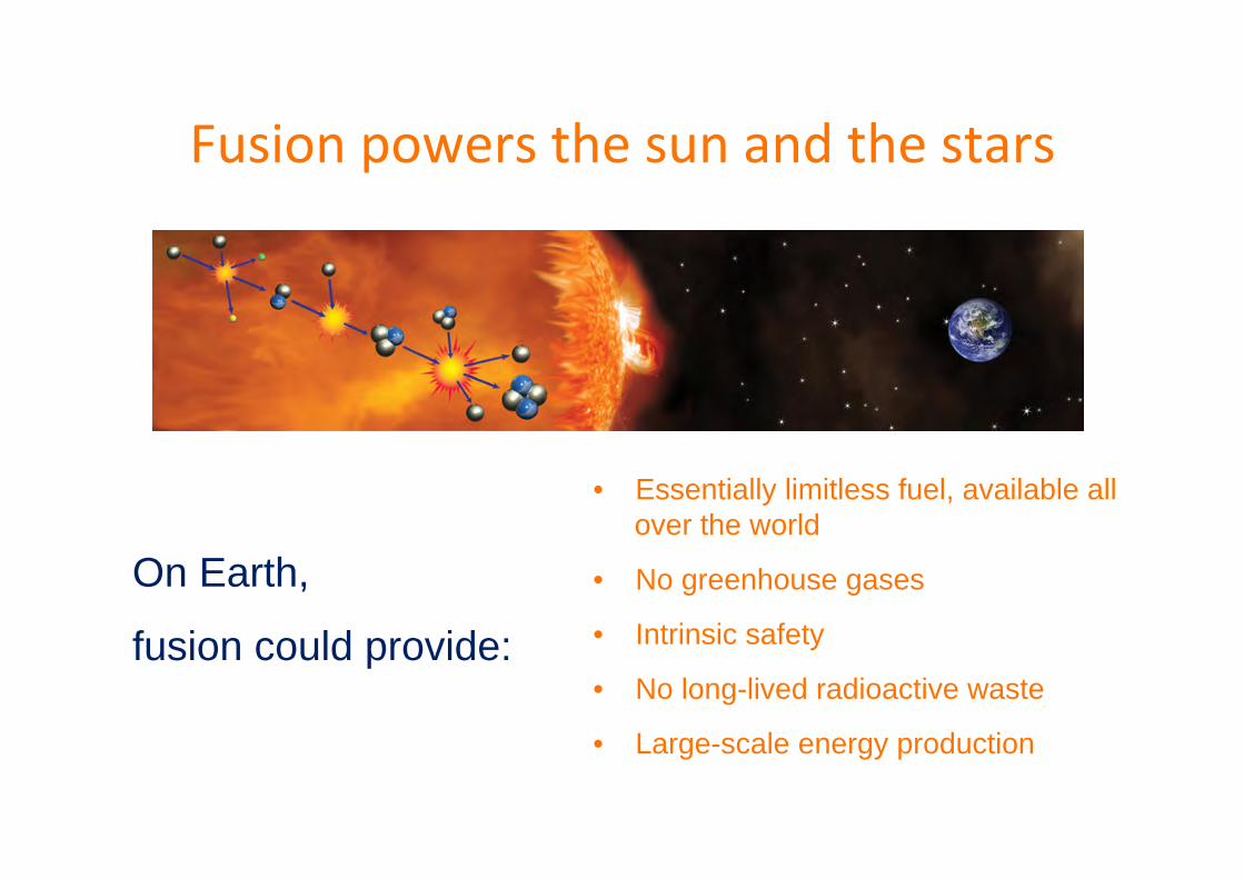
Fusion powers the sun and the stars
• Essentially limitless fuel, available all over the world
• No greenhouse gases
• Intrinsic safety
• No long-lived radioactive waste
• Large-scale energy production
On Earth,
fusion could provide:

The Fusion ReacBon on Earth “... is not the same as in the Sun“
+ 3.5 MeV
+ 14.1 MeV
41H + 2e --> 4He + 2 υ+ 6 γ + 26.7 MeV (solar process)

Why D-‐T ?: Cross secBon!

Fusion Fuel
Raw fuel of a fusion reactor is water and lithium*
Lithium in one laptop battery + half a bath-full of ordinary water (-> one egg cup full of heavy water) 200,000 kW-hours = (current UK electricity average consumption) for 30 years * Deuterium/hydrogen = 1/6700
+ tritium from: neutron (from fusion) + lithium → tritium + helium
CH4 + 2O2 --> CO2 + 2H2O + 5.5 eV (Chemical) 2D + 3T --> He + n + 17.6 MeV (Fusion)
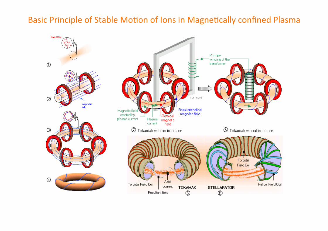
Basic Principle of Stable MoBon of Ions in MagneBcally confined Plasma

Reactor conditions
ITER
Progress in fusion performance

Author’s name | Place, Month xx, 2007 | Event 10 B. Carvalho | EIROforum School on Instrumentation, ESI 2011 | Grenoble
Control for Fusion Performance
Fusion Control System is a tool to achieve and maintain plasma condi6ons with best performance for • plasma physics invesBgaBons • energy confinement and stability
• and -‐ at the end -‐ fusion power yield

Author’s name | Place, Month xx, 2007 | Event 11 B. Carvalho | EIROforum School on Instrumentation, ESI 2011 | Grenoble
Benchmark for Fusion Performance
• The aim is to generate power: Pfusion/Pheat↑ – Pfusion~(nT)2 : power expelled (lost) with fusion neutrons – Pheat : power needed to sustain plasma
• from external heaBng • from α heaBng (dominaBng in a reactor)
• For present-‐day experiments alpha α heaBng can be neglected: Pheat=Wplasma/τE and Wplasma~nT – Wplasma: thermal energy – τE :energy confinement Bme (thermal insulaBon)
• So: Pfusion/Pheat ~n⋅ T ⋅ τE (fusion product)

Author’s name | Place, Month xx, 2007 | Event 12 B. Carvalho | EIROforum School on Instrumentation, ESI 2011 | Grenoble
Strategies to Improve the Fusion Product
• Simply increasing each individual factor does not work: Complex limits restrict operational space.
• Limits depend on spatial distribution of the quantities (profiles).
• Each actuator affects multiple factors. • We need to find transition paths to
plasmas with suitable combinations of n, T and τE.
Optimise the fusion product n⋅T⋅τE by • n↑ : increasing density • n⋅T ↑ : increasing pressure • τE ↑ : increasing confinement • Ip↑ : increasing current
Tip: PLAY with the virtual tokamak at http://w3.pppl.gov/~dstotler/SSFD

Author’s name | Place, Month xx, 2007 | Event 13 B. Carvalho | EIROforum School on Instrumentation, ESI 2011 | Grenoble
Applications of Performance Control in Fusion
Presently, Performance Control is not a monolithic application but a composition of various tools.
Simple • Electron/Neutral
Density Control • Radiation Control • H/D (Isotopes)
Control • beta control
Advanced • Gap/Shape Control • VS Control • Profile Control
(current, density, temperature)
• MHD Control
Protection • Disruption Prediction,
Avoidance and Mitigation
• Hot-Spot Detection • Radiation Peaking

Author’s name | Place, Month xx, 2007 | Event 14 B. Carvalho | EIROforum School on Instrumentation, ESI 2011 | Grenoble
Rationale for Fusion Performance Control
Performance Control is a tool • to guide plasma state to a desired domain (scenario,
regime) on prescribed paths • to simplify the plant operation scheme
replacing actuator inputs by higher level control variables
linearizing and decoupling the system behaviour • to increase the safety margin to critical limits • to counteract external disturbances • compensate for incomplete system knowledge
For This
Feedback from measured quantities is Essential.

Author’s name | Place, Month xx, 2007 | Event 15 B. Carvalho | EIROforum School on Instrumentation, ESI 2011 | Grenoble
r ControllerC(s)
e u PlantP(s)
y
FeedbackF(s)
-
reference error command Outputr Closed-Loop
Hcl(s)y
=
Feedback Control System Basics: LTI Systems
r ControllerC(s)
u PlantP(s)
y
reference error command Output
)()()( sRsCsU =
)()()()( sYsFsRsE −= )()()()()()(1
)()()( sRsHsRsCsPsF
sCsPsY cl=+
=
)()()(1)()()(
sCsPsFsCsPsHcl +
=
Closed-‐loop transfer funcBon of the system
)()()( sCsPsHo =
Open-‐Loop transfer funcBon of the system
)()()()()()()()( sRsHsRsCsPsUsPsY o===
Transfer Functions are represented in frequency (Laplace) domain rather than in time domain.
{ } dttfetfLsF st )()()(0∫∞ −==
iws +=σ

Author’s name | Place, Month xx, 2007 | Event 16 B. Carvalho | EIROforum School on Instrumentation, ESI 2011 | Grenoble
Control Loop with Disturbance
C l o s e d -‐ l o o p transfer funcBon
r ControllerC(s)
e u PlantP(s)
y
FeedbackF(s)
-
reference errordisturbance
Outputd
))()()()(()()()()()()()()( sYsFsRsCsPsDsPsUsPsDsPsY −+=+=
)()()()()()()()()()( sRsCsPsDsPsYsFsCsPsY +=+
)()()()(1
)()()()()()(1
)()( sRsFsCsP
sCsPsDsFsCsP
sPsY+
++
=
)()()()()()( sRsHsD
sCsHsY cl
cl +=

Author’s name | Place, Month xx, 2007 | Event 17 B. Carvalho | EIROforum School on Instrumentation, ESI 2011 | Grenoble
Feed-Forward Control
r ControllerC(s)
e u PlantP(s)
y
FeedbackF(s)
-
reference errordisturbance
Outputdff
feedfoward
• same entry point in the loop as standard disturbance input • difference: synchronized with the reference • predicBon of required actuator command values
GOAL: • test control scenarios without stability concerns • provide adequate iniBal values when switching on a controller • shortcut and speed-‐up control reacBon

Author’s name | Place, Month xx, 2007 | Event 18 B. Carvalho | EIROforum School on Instrumentation, ESI 2011 | Grenoble
Transfer Function: Poles and Zeros
)sin()()(2
)(
)()(
222 ϕ+=⇒+++
+=
=⇒+
=
−
−
wtCetywaass
BAssY
Aetyas
AsY
at
at
)(...)()(...)(
......)(
1
1
10
10
n
mmn
n
mm
pspsqsqsb
sbasaasbsbbsH
+⋅⋅+
+⋅⋅+=
+++
+++=
Zeros q1,..., qm : M complex roots of the transfer funcBon numerator
Poles p1,..., pn : N complex roots of the transfer funcBon denominator
n>= m CAUSALITY CONSTRAIN
Single real pole (|a|>0; p = -‐a)
Pair of complex poles (|a|>0; p = -‐a ± i w)
Examples:
Re
Im
p1 qi pp
Pp*
pa

Author’s name | Place, Month xx, 2007 | Event 19 B. Carvalho | EIROforum School on Instrumentation, ESI 2011 | Grenoble
Pole Positioning
Can be roughly denoted as follows:
Re
Im
RHP Not allowed
LHP
Too oscillatory
Good/ok Good/fast
OK
Too slow
Debatable

Author’s name | Place, Month xx, 2007 | Event 20 B. Carvalho | EIROforum School on Instrumentation, ESI 2011 | Grenoble
Control Stability: Effects of Closing the Loop
)()()()()()(1
)()()( sRsHsRsCsPsF
sCsPsY cl=+
=
)()()(1)()()(
sCsPsFsCsPsHc +
=
• Feedback preserves the zeros • moves the poles (alters the denominator) • can stabilize but also destabilize!
r ControllerC(s)
e u PlantP(s)
y
FeedbackF(s)
-
reference error command Output
)()()( sCsPsHo =
A controller changes the dynamic behavior of the closed loop system – But how ? There is no simple analytical formula to translate controller parameters to closed loop poles and zeros • Ideal method: pole-placement
requires full feedback of all state variables, or reconstruction by observers potentially complex can be compromised by parasitic delays
• Pragmatic method: frequency response shaping
infer characteristic properties from open loop to closed loop live with approximations and incomplete models more robust, less performing

Author’s name | Place, Month xx, 2007 | Event 21 B. Carvalho | EIROforum School on Instrumentation, ESI 2011 | Grenoble
Impact of sensor dynamics in the feedback loop
r ControllerC(s)
e u PlantP(s)
y
FeedbackF(s)
-
reference error command Output
Gain inversion: )(1)( ∞→=∞→ trK
tyf
Sensors are in the feedback branch of the loop
)()()()()()()(
)()(
)()(1
)()()()()(1
)()()(sQsCsPsP
sPsCsP
sPsQ
sCsP
sCsPsFsCsP
sCsPsHff
f
f
fc +
=+
=+
=
)()(
)(sPsQ
sFf
f=
Poles of F(s) become Zeros of Hc(s)

Author’s name | Place, Month xx, 2007 | Event 22 B. Carvalho | EIROforum School on Instrumentation, ESI 2011 | Grenoble
Impact of delays in the control loop
Originators of delays: • Digital control systems • Digital data processors (real-‐Bme diagnosBcs) • Event counBng sensors • Switching power supplies (e.g. thyristor converters)
Transfer function for a delay in time dsTd esFT −=⇒ )(
• Constant gain, no damping at all frequencies
1)( =ωiF
• But conBnuously increasing phase delay : limits the achievable bandwidth of the closed loop • Transcendent funcBon (not representable by poles and zeros)
ωω ⋅−=∠ dTiF )(
• TIP: keep measurement delays short (e.g. filtering, computer network communicaBon latencies)

Author’s name | Place, Month xx, 2007 | Event 23 B. Carvalho | EIROforum School on Instrumentation, ESI 2011 | Grenoble
Example: Plasma Density Control
3) IdenBfy Parameters and Simplify
Plant
F Density build-up
no Transportne(core)
Pumping
-
Commandgas flux
disturbance (wall influx)Outputd
01.01 =K
sssP
025.011
1.0101.0)(
+⋅
+=
1) Describe behaviour
Plant
F no ne
-
Commandgas flux
disturbanceOutput
d
sKdens
1
pumpK
transp
transp
sTK+1
2) Formulate Model
Plant P(s)
F no ne
Commandgas flux Output
transp
transp
sTK+1
1
1
1 sTK
+
sec1.01 =T1=transpK sec025.01 =T
)40()10(4
)025.01()1.01(01.0)(
+⋅+=
+⋅+=
sssssP
DC gain (s=0): K= 0.01

Author’s name | Place, Month xx, 2007 | Event 24 B. Carvalho | EIROforum School on Instrumentation, ESI 2011 | Grenoble
Controlling the example: Proportional Control
nref
-
Plant P(s)
e no ne
Commandgas flux Output
transp
transp
sTK+1
1
1
1 sTK
+
1=K
F100=PK
Unity Feedback
P-controller
Add some: Feedback (Unity) Controller (ProporBonal)
Simulate! Beeer sBll: if you have a Tokamak nearby: TRY-‐IT!!
Steady State Error (SSE): Lets increase KP to 500?
P
P
P
P
cl KssK
ssK
ssK
sH⋅++⋅+
⋅=
+⋅+⋅+
+⋅+⋅
=4)40()10(
4
)40()10(41
)40()10(4
)(
SSE error

Author’s name | Place, Month xx, 2007 | Event 25 B. Carvalho | EIROforum School on Instrumentation, ESI 2011 | Grenoble
Increasing K by Trial & Error
Now we have Overshoot
P
Pcl Kss
KsH⋅++⋅+
⋅=
4)40()10(4)(
K = 500

Author’s name | Place, Month xx, 2007 | Event 26 B. Carvalho | EIROforum School on Instrumentation, ESI 2011 | Grenoble
Improving the Density control: Integration Controller
nref
-
Plant P(s)
e no ne
Commandgas flux Output
transp
transp
sTK+1
1
1
1 sTK
+
1=K
F
100=IK
Unity Feedback
I-controllersKI
I
I
I
I
cl KsssK
sssK
sssK
sH⋅++⋅+⋅
⋅=
+⋅+⋅+
+⋅+⋅
=4)40()10(
4
)40()10(41
)40()10(4
)(
AeenBon: the controlled loop could get unstable !

Author’s name | Place, Month xx, 2007 | Event 27 B. Carvalho | EIROforum School on Instrumentation, ESI 2011 | Grenoble
Real-Time Diagnostics
Robust Density control
ne* Controller
C(s)e u Plant
P(s)ne
DCN interferometer
-
reference error Outputff
F
feedfoward
Bremstrahlung
Coton MoutonEffect
Reconstructor:Compute
best estimate
Command
Requirement • DCN signals can be compromised by fringe jumps. • Density measurement from a single central DCN line-of-sight (LOS) is unsecure. • Density from Bremsstrahlung has drifts. • A valid density value is required for control and monitoring (NBI interlocks)
RealisaBon: Compute a validated density from several diagnosBc sources o detect sensor failures o replace with other inputs

Author’s name | Place, Month xx, 2007 | Event 28 B. Carvalho | EIROforum School on Instrumentation, ESI 2011 | Grenoble
ITER CODAC is the primary tool for operation

Author’s name | Place, Month xx, 2007 | Event 29 B. Carvalho | EIROforum School on Instrumentation, ESI 2011 | Grenoble
ITER CODAC is a challenging endeavour
ITER will require a far higher level of availability and reliability than previous/
existing Tokamaks .
• ITER will generate a huge quantity of
experimental data
– 150 plant systems – 1 000 000 diagnostic channels – 300 000 slow control channels – 5 000 fast control channels – 40 CODAC systems – 5 Gb/s data – 3Pb/year data (e.g. 12 IR cameras in a 10 minutes discharge: 1.728
Tbytes) In addition...

Author’s name | Place, Month xx, 2007 | Event 30 B. Carvalho | EIROforum School on Instrumentation, ESI 2011 | Grenoble
International ITER Agreement
140 slices
Procurement “IN KIND”
Need for Standards in HW & SW Architecture
IO Team in charge of the integration on site and the operation

Author’s name | Place, Month xx, 2007 | Event 31 B. Carvalho| EIROforum School on Instrumentation, ESI 2011 | Grenoble
ITER Subsystem is a set of related plant system I&C
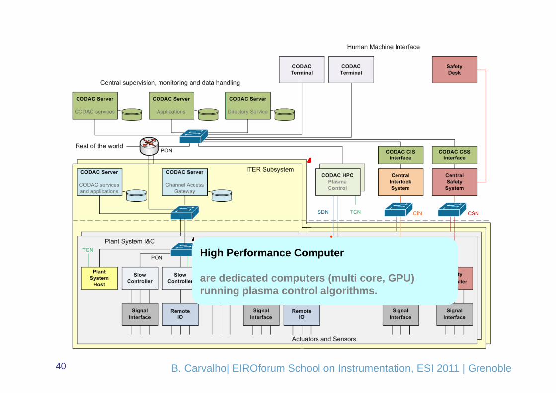
ITER Instrumentation & Control System physical architecture
Author’s name | Place, Month xx, 2007 | Event 32 B. Carvalho| EIROforum School on Instrumentation, ESI 2011 | Grenoble
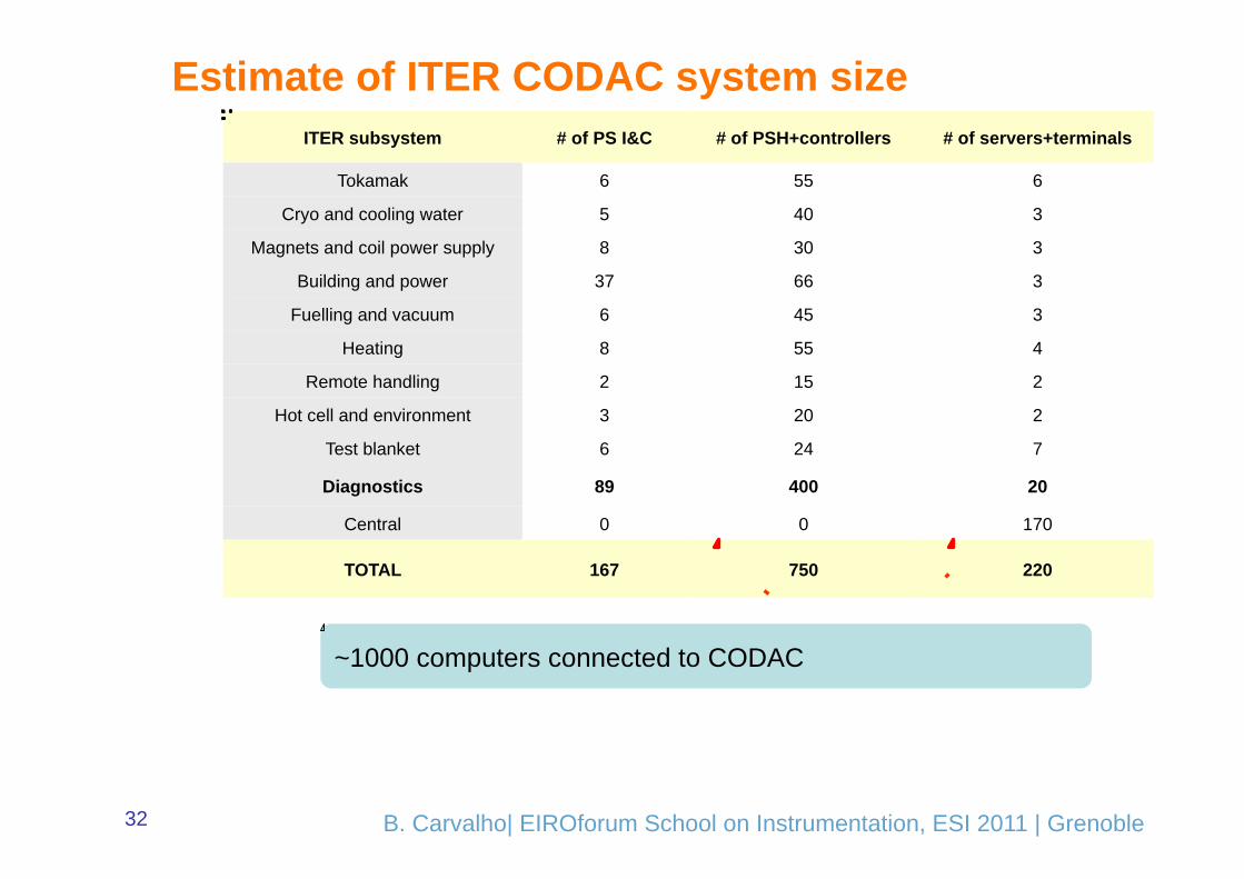
ITER subsystem # of PS I&C # of PSH+controllers # of servers+terminals
Tokamak 6 55 6
Cryo and cooling water 5 40 3
Magnets and coil power supply 8 30 3
Building and power 37 66 3
Fuelling and vacuum 6 45 3
Heating 8 55 4
Remote handling 2 15 2
Hot cell and environment 3 20 2
Test blanket 6 24 7
Diagnostics 89 400 20
Central 0 0 170
TOTAL 167 750 220
Estimate of ITER CODAC system size
~1000 computers connected to CODAC

Author’s name | Place, Month xx, 2007 | Event 33 B. Carvalho| EIROforum School on Instrumentation, ESI 2011 | Grenoble
Plant System I&C Is a deliverable by ITER member state. Set of standard components selected from catalogue. One and only one plant system host.
ITER Instrumentation & Control System physical architecture

Author’s name | Place, Month xx, 2007 | Event 34 B. Carvalho| EIROforum School on Instrumentation, ESI 2011 | Grenoble
CODAC Servers and Terminals are servers running Red Hat Enterprise Linux (RHEL) and EPICS/CSS/???. These servers implements supervision, monitoring, coordination, configuration, automation, data handling, archiving, visualization, HMI…

Author’s name | Place, Month xx, 2007 | Event 35 B. Carvalho| EIROforum School on Instrumentation, ESI 2011 | Grenoble
Plant Operation Network is the work horse general purpose flat network utilizing industrial managed switches and mainstream IT technology

Author’s name | Place, Month xx, 2007 | Event 36 B. Carvalho| EIROforum School on Instrumentation, ESI 2011 | Grenoble
High Performance Networks are physically dedicated networks to implement functions not achievable by the conventional Plant Operation Network. These functions are distributed real-time feedback control, high accuracy time synchronization and bulk video distribution.

Author’s name | Place, Month xx, 2007 | Event 37 B. Carvalho| EIROforum School on Instrumentation, ESI 2011 | Grenoble
Slow Controller is a Siemens Simatic S7 industrial automation Programmable Logic Controller (PLC A Slow Controller runs software and plant specific logic programmed on STEP 7. A Slow Controller has normally I/O and IO supports a set of standard I/O modules.

Author’s name | Place, Month xx, 2007 | Event 38 B. Carvalho| EIROforum School on Instrumentation, ESI 2011 | Grenoble
Fast Controller is a dedicated industrial controller implemented in PCI family form factor and There may be zero, one or many Fast Controllers in a Plant System I&C. A Fast Controller runs LINUX RHEL and EPICS IOC. A Fast Controller has normally I/O and IO supports a set of standard I/O modules with associated EPICS drivers. A Fast Controller may have interface to High Performance Networks (HPN),

Author’s name | Place, Month xx, 2007 | Event 39 B. Carvalho| EIROforum School on Instrumentation, ESI 2011 | Grenoble
High Performance Networks are physically dedicated networks to implement functions not achievable by the conventional Plant Operation Network..
Author’s name | Place, Month xx, 2007 | Event 40 B. Carvalho| EIROforum School on Instrumentation, ESI 2011 | Grenoble
High Performance Computer are dedicated computers (multi core, GPU) running plasma control algorithms.

Author’s name | Place, Month xx, 2007 | Event 41 B. Carvalho | EIROforum School on Instrumentation, ESI 2011 | Grenoble
Fast Controllers for Fusion Devices
Actuators
Plasma
SensorsHeating systems
Fueling systems
Corrective systems
Diagnostics
Analysis codes
Magnetic coils
ControllersPlasma Shaping
&Current Control
Machine protection
Profiles control
High performance communication networks
Supporting InfrastructureSimulation environment
Scheduler
R-‐T signal servers
Instabilities control

Author’s name | Place, Month xx, 2007 | Event 42 B. Carvalho | EIROforum School on Instrumentation, ESI 2011 | Grenoble
Vertical Stabilization | an example
Elongated plasmas are vertically unstable MIMO systems designed to make plasma vertically stable while other controllers control plasma position and shape
Growth Rate

Author’s name | Place, Month xx, 2007 | Event 43 B. Carvalho | EIROforum School on Instrumentation, ESI 2011 | Grenoble
ITER Vertical Position Control How important are control systems?
• Loss of vertical plasma position control in ITER will cause thermal loads on Plasma Facing Components of 30-60 MJ/m2 for ~0.1s.
– PFCs cannot be designed to sustain such (repetitive) thermal loads
• Vertical Displacement Events also generates the highest electromagnetic loads – A phenomenological extrapolation of horizontal forces estimates loads
~45MN on ITER vacuum vessel. – Simulations of MHD predicts ~20MN – Vertical loads ~90MN
Plasma vertical position in ITER must be robust & reliable to ensure a vertical plasma position control
loss is a very unlikely event

Author’s name | Place, Month xx, 2007 | Event 44 B. Carvalho | EIROforum School on Instrumentation, ESI 2011 | Grenoble
• 192 signals acquired by ADCs and transferred at each cycle
• 50 µs control loop cycle time with jitter < 1 µs archieved by MARTe.
• Always in real-time (24 hours per day)
• 1.728 x 10⁹ 50 µs cycles/day
• Crucial for ITER very long pulses
Example: JET Vertical Stabilization system
192 input signals
Front view

Author’s name | Place, Month xx, 2007 | Event 45 B. Carvalho | EIROforum School on Instrumentation, ESI 2011 | Grenoble
ATCA @ JET Ver6cal Stabilisa6on Controller
• x86-based ATCA controller
• Up to 12 DGP cards (PCIe links through the ATCA full mesh backplane)
• 32 18 bit ADC channels / board , separately isolated (1 kV) • Parallel execution on FPGAs for MIMO signal processing (Control loop delay < 50 µs, aim < 10 µs)
• Linux RT operating system (RTAI)
• Aurora and PCI Express communication protocols allow data transport, between modules - expected latencies below 2 µs.

Author’s name | Place, Month xx, 2007 | Event 46 B. Carvalho | EIROforum School on Instrumentation, ESI 2011 | Grenoble
IPFN’s ATCA-MIMO-ISOL I/O Processing Boards
RTM ADC module

Author’s name | Place, Month xx, 2007 | Event 47 B. Carvalho | EIROforum School on Instrumentation, ESI 2011 | Grenoble
ATCA JET Gamma ray Spectroscopy
• 19 lines of sight 10 Horizontal + 9 Vertical Channels
• 2 FPGA ( Virtex II-Pro) ATCA Boards Digitizing at 200 MSPS, 13bit, 8 channels

Author’s name | Place, Month xx, 2007 | Event 48 B. Carvalho | EIROforum School on Instrumentation, ESI 2011 | Grenoble
Gamma and X-ray Diagnostics Real time Processing
Analog-to-Digital
Converter Block
Analog-to-Digital Converter BlockAnalog-to-Digital Converter Block
DDR SODIMM 1 GBYTES
XilinxTMFPGA
VirtexII-ProXC2VP30FF1152 -6
Clock Synthesis
SYSTEM ACE COMPACT
FLASH
Analog-to-Digital Converter Block 4x 12 bits
Sync
Ref CLK
Analog Inputs
Analog-to-Digital
Converter Block
Analog-to-Digital Converter BlockAnalog-to-Digital Converter Block
DDR SODIMM 1 GBYTES
XilinxTMFPGA
VirtexII-ProXC2VP30FF1152 -6
Clock Synthesis
PCI Express x4 link
Analog-to-Digital Converter Block 4x 12 bitsAnalog Inputs
PCI EXPRESS SWITCHPex 8516
4X Rocket IO
4X Rocket IO
PCI Express x4 link
Channel 11
Channel 12
• Parallel DPP in FPGA • Real-Time PHA at 1MHz average pulse
rate. • 20 ns resolution timestamp • Data reduction rate of at least 80%
attainable 95% of total pulses resolved

Author’s name | Place, Month xx, 2007 | Event 49 B. Carvalho | EIROforum School on Instrumentation, ESI 2011 | Grenoble
Why ATCA?
ATCA platform is gaining traction in the physics community because of • Advanced communication bus architecture (serial gigabit replacing parallel buses) • very high data throughput options and its suitability for real-time applications • Scalable shelf capacity to 2.5Tb/s • Scalable system availability to 99.999% • Robust power infrastructure (distributed 48V power system) and large cooling
capacity (cooling for 200W per board) • Ease of integration of multiple functions and new features • The ability to host large pools of DSPs, NPs, processors and storage • Full redundancy support • Reliable mechanics (serviceability, shock and vibration) • Hardware management interface (IPMI Bus)

Author’s name | Place, Month xx, 2007 | Event 50 B. Carvalho | EIROforum School on Instrumentation, ESI 2011 | Grenoble
Who else is using ATCA?
The group of experimenters includes several major laboratories representing different fields of use and a range of applications.
• Active programs are showing up most notably at – DESY for XFEL and JET
• Other laboratories – ILC, IHEP, KEK, SLAC, FNAL, ANL, BNL, FAIR, ATLAS at CERN, AGATA, large telescopes,
Ocean Observatories
• Investigating ATCA solutions for future upgrades – Both the CMS and ATLAS detectors
• Setting up prototype experiments to test its potential – ILC and ITER
ATCA is being adapted without significant change as a platform for generic data acquisition processors requiring high throughput and bandwidth.
Most of these programmes put the emphasis on High Availability

Author’s name | Place, Month xx, 2007 | Event 51 B. Carvalho | EIROforum School on Instrumentation, ESI 2011 | Grenoble
SOFTWARE TOOLS FOR CONTROL: EPICS and ITER
In February 2009 ITER Organization decided to use EPICS for the control system. This decision was based on three independent studies In February 2010 ITER-IO released the first version (V1.0) of CODAC Core System, which basically is a package of selected EPICS products

Author’s name | Place, Month xx, 2007 | Event 52 B. Carvalho | EIROforum School on Instrumentation, ESI 2011 | Grenoble
What is EPICS?
EPICS is: • A collaboration • A tool kit • A control system architecture
EPICS is an abbreviation for: Experimental Physics and Industrial Control System

Author’s name | Place, Month xx, 2007 | Event 53 B. Carvalho | EIROforum School on Instrumentation, ESI 2011 | Grenoble
The History – In1989 started a collaboration between Los Alamos
National Laboratory (GTA) and Argonne National Laboratory (APS)
(Bob Dalesio & Marty Kraimer)
– More than 150 licenses agreements were signed, before EPICS became Open Source in 2004
– Team work on problems, for example over “Tech Talk” mailing list
– Database and network protocol (CA) basically unchanged since 1990.
– Collaborative efforts vary • Assistance in finding bugs • Share tools, schemes, and advice
GTA: Ground Test Accelerator APS: Advanced Photon Source
http://www.aps.anl.gov/epics

Author’s name | Place, Month xx, 2007 | Event 54 B. Carvalho | EIROforum School on Instrumentation, ESI 2011 | Grenoble
EPICS – who is using it?
Some members of the collaboration (very short List!):
– ANL (APS Accelerator, APS Beamlines, IPNS) in Chicago, USA – LANL in Los Alamos, USA – ORNL (SNS) in Oak Ridge, USA – SLAC (SSRL, LCLS) in Standford, USA – DESY in Hamburg, Germany – BESSY in Berlin, Germany – PSI (SLS) in Villigen, Switzerland – KEK in Tsukuba, Japan – DIAMOND Light Source (Rutherford Appleton Laboratory) in
Oxfordshire, England – In FUSION: NTSX, KSTAR, ITER and ISTTOK

Author’s name | Place, Month xx, 2007 | Event 55 B. Carvalho | EIROforum School on Instrumentation, ESI 2011 | Grenoble
Parts of EPICS
Commercial Instruments
IOC IOC
IOC
IOC CAS
CAS
Custom hardware
Technical Equipment
Out
put
Input
Client Software MEDM
ALH StripTool TCL/TK
Perl Scripts
OAG Apps
Many, many others …
Channel Access
CA Server Software EPICS Database
consists of Process Variables Custom Programs
Realtime control
Sequence Programs
Records

Author’s name | Place, Month xx, 2007 | Event 56 B. Carvalho | EIROforum School on Instrumentation, ESI 2011 | Grenoble
How does it do it?
Power Supply
Beam Position Monitor
Vacuum Gauge
Computer Interface
Computer Interface
Computer Interface
Process Variables:
Channel Access Server
S1A:H1:CurrentAO
S1:P1:x
S1:P1:y
S1:G1:vacuum
Channel Access Client
Channel Access Client
Channel Access Client
Network (Channel Access Protocol)
Machine
Operator
IOC

Author’s name | Place, Month xx, 2007 | Event 57 B. Carvalho | EIROforum School on Instrumentation, ESI 2011 | Grenoble
What is an IOC? • A special CA Server and CA Client • A computer running “IOC Core” • This computer may be:
- VME based, operating system vxWorks or RTEMS - PC, operating system Windows, Linux, RTEMS - Apple, operating system OSX - UNIX Workstation, operating system Solaris
• An IOC normally is connected to input and/or output hardware • An EPICS control system is based on at least one Channel Access Server (normally an IOC) • An IOC runs a record database, which defines what this IOC is doing
IOC means Input Output Controller
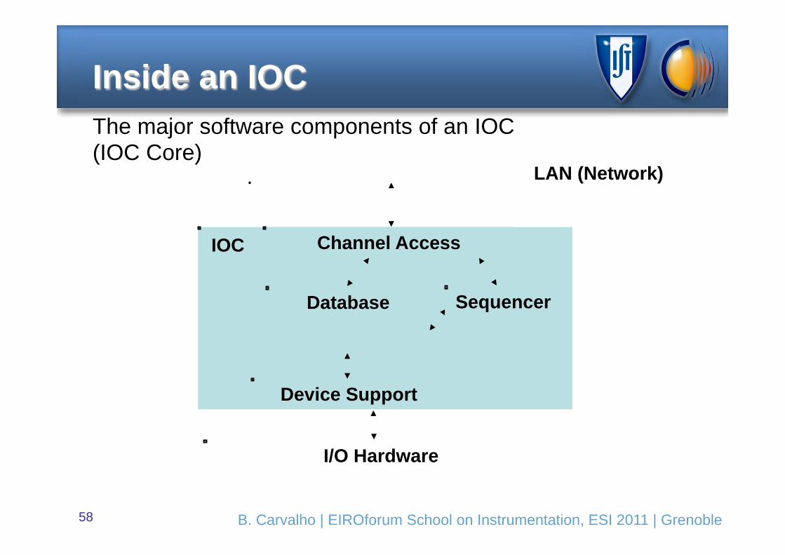
Author’s name | Place, Month xx, 2007 | Event 58 B. Carvalho | EIROforum School on Instrumentation, ESI 2011 | Grenoble
Sequencer
Inside an IOC
LAN (Network)
Device Support
I/O Hardware
IOC
The major software components of an IOC (IOC Core)
Database
Channel Access

Author’s name | Place, Month xx, 2007 | Event 59 B. Carvalho | EIROforum School on Instrumentation, ESI 2011 | Grenoble
Control and Data Acquisition for Next Generation Fusion Experiments
Challenges • Increasing number of interdependent parameters to be controlled
• Increasingly faster real-‐Bme loop-‐cycle response
• Stricter OperaBng Safety Margins
• ConBnuous OperaBon generaBon huge data quanBBes
Implica6ons • Massive processing power (parallel, mulB-‐processing support)
• High bandwidth for data-‐transfer
• Real-‐Bme mulB-‐input-‐mulB-‐output (MIMO) control
• Advanced, intelligent, flexible Bming & syncronizaBon

Author’s name | Place, Month xx, 2007 | Event 60 B. Carvalho | EIROforum School on Instrumentation, ESI 2011 | Grenoble
Concluding remarks
• High performance of fusion depends on real-time MIMO control systems
• Control systems are critical for safe operation and reliability of Fusion Devices
• ITER is a big challenge for its higher complexity and stricter safety margins
• Likely there were will be a grater convergence between Neutron/High energy physics and Fusion on hardware technologies in hardware (ATCA) and software (EPICS)

Her