contrail service orchestration user guide - juniper.netcloning,anddeletingantispamprofiles.....407...
TRANSCRIPT
Contrail Service Orchestration User Guide
Release
3.3
Modified: 2018-06-18
Copyright © 2018, Juniper Networks, Inc.
Juniper Networks, Inc.1133 InnovationWaySunnyvale, California 94089USA408-745-2000www.juniper.net
Juniper Networks, the Juniper Networks logo, Juniper, and Junos are registered trademarks of Juniper Networks, Inc. and/or its affiliates inthe United States and other countries. All other trademarks may be property of their respective owners.
Juniper Networks assumes no responsibility for any inaccuracies in this document. Juniper Networks reserves the right to change, modify,transfer, or otherwise revise this publication without notice.
Contrail Service Orchestration User Guide3.3Copyright © 2018 Juniper Networks, Inc. All rights reserved.
The information in this document is current as of the date on the title page.
YEAR 2000 NOTICE
Juniper Networks hardware and software products are Year 2000 compliant. Junos OS has no known time-related limitations through theyear 2038. However, the NTP application is known to have some difficulty in the year 2036.
ENDUSER LICENSE AGREEMENT
The Juniper Networks product that is the subject of this technical documentation consists of (or is intended for use with) Juniper Networkssoftware. Use of such software is subject to the terms and conditions of the End User License Agreement (“EULA”) posted athttps://www.juniper.net/support/eula/. By downloading, installing or using such software, you agree to the terms and conditions of thatEULA.
Copyright © 2018, Juniper Networks, Inc.ii
Table of Contents
About the Documentation . . . . . . . . . . . . . . . . . . . . . . . . . . . . . . . . . . . . . . . . . . xxxv
Documentation and Release Notes . . . . . . . . . . . . . . . . . . . . . . . . . . . . . . . xxxv
Documentation Conventions . . . . . . . . . . . . . . . . . . . . . . . . . . . . . . . . . . . . xxxv
Documentation Feedback . . . . . . . . . . . . . . . . . . . . . . . . . . . . . . . . . . . . . . xxxvii
Requesting Technical Support . . . . . . . . . . . . . . . . . . . . . . . . . . . . . . . . . . xxxviii
Self-Help Online Tools and Resources . . . . . . . . . . . . . . . . . . . . . . . . xxxviii
Opening a Case with JTAC . . . . . . . . . . . . . . . . . . . . . . . . . . . . . . . . . . xxxviii
Part 1 Administration Portal
Chapter 1 Introduction . . . . . . . . . . . . . . . . . . . . . . . . . . . . . . . . . . . . . . . . . . . . . . . . . . . . . . . 3
Unified Administration and Customer Portal Overview . . . . . . . . . . . . . . . . . . . . . . 3
Administration Portal Overview . . . . . . . . . . . . . . . . . . . . . . . . . . . . . . . . . . . . . . . . . 4
Logging in to Administration Portal . . . . . . . . . . . . . . . . . . . . . . . . . . . . . . . . . . . . . . 5
Switching the Tenant Scope . . . . . . . . . . . . . . . . . . . . . . . . . . . . . . . . . . . . . . . . . . . 5
Changing the Administration Portal Password . . . . . . . . . . . . . . . . . . . . . . . . . . . . . 6
Changing the Password on First Login . . . . . . . . . . . . . . . . . . . . . . . . . . . . . . . . . . . . 7
Resetting the Password . . . . . . . . . . . . . . . . . . . . . . . . . . . . . . . . . . . . . . . . . . . . . . . 8
Setting Password Duration . . . . . . . . . . . . . . . . . . . . . . . . . . . . . . . . . . . . . . . . . . . . 9
Extending the User Login Session . . . . . . . . . . . . . . . . . . . . . . . . . . . . . . . . . . . . . . 10
Setting Up the Cloud CPE Centralized Deployment Model with Administration
Portal . . . . . . . . . . . . . . . . . . . . . . . . . . . . . . . . . . . . . . . . . . . . . . . . . . . . . . . . . 10
Setting Up the Cloud CPE Distributed Deployment Model with Administration
Portal . . . . . . . . . . . . . . . . . . . . . . . . . . . . . . . . . . . . . . . . . . . . . . . . . . . . . . . . . . 11
Chapter 2 Managing Objects . . . . . . . . . . . . . . . . . . . . . . . . . . . . . . . . . . . . . . . . . . . . . . . . . 13
Creating Objects . . . . . . . . . . . . . . . . . . . . . . . . . . . . . . . . . . . . . . . . . . . . . . . . . . . . 13
Modifying an Object . . . . . . . . . . . . . . . . . . . . . . . . . . . . . . . . . . . . . . . . . . . . . . . . . 13
Deleting Objects . . . . . . . . . . . . . . . . . . . . . . . . . . . . . . . . . . . . . . . . . . . . . . . . . . . . 14
Viewing Object Details . . . . . . . . . . . . . . . . . . . . . . . . . . . . . . . . . . . . . . . . . . . . . . . 14
Searching for Text in an Object Data Table . . . . . . . . . . . . . . . . . . . . . . . . . . . . . . . 15
Sorting Objects . . . . . . . . . . . . . . . . . . . . . . . . . . . . . . . . . . . . . . . . . . . . . . . . . . . . . 15
Chapter 3 Using the Dashboard . . . . . . . . . . . . . . . . . . . . . . . . . . . . . . . . . . . . . . . . . . . . . . . 17
About the Administration Portal Dashboard . . . . . . . . . . . . . . . . . . . . . . . . . . . . . . 17
Tasks You Can Perform . . . . . . . . . . . . . . . . . . . . . . . . . . . . . . . . . . . . . . . . . . . 17
Field Descriptions . . . . . . . . . . . . . . . . . . . . . . . . . . . . . . . . . . . . . . . . . . . . . . . . 17
iiiCopyright © 2018, Juniper Networks, Inc.
Chapter 4 Monitoring Alerts, Alarms, and Device Events . . . . . . . . . . . . . . . . . . . . . . . . . 19
About the Monitor Overview Page . . . . . . . . . . . . . . . . . . . . . . . . . . . . . . . . . . . . . . 19
Tasks You Can Perform . . . . . . . . . . . . . . . . . . . . . . . . . . . . . . . . . . . . . . . . . . . 19
Field Descriptions . . . . . . . . . . . . . . . . . . . . . . . . . . . . . . . . . . . . . . . . . . . . . . . 19
About the Generated Alerts Page . . . . . . . . . . . . . . . . . . . . . . . . . . . . . . . . . . . . . . 20
Tasks You Can Perform . . . . . . . . . . . . . . . . . . . . . . . . . . . . . . . . . . . . . . . . . . . 20
Field Descriptions . . . . . . . . . . . . . . . . . . . . . . . . . . . . . . . . . . . . . . . . . . . . . . . 20
About the SD-WAN Alert Definitions Page . . . . . . . . . . . . . . . . . . . . . . . . . . . . . . . 21
Tasks You Can Perform . . . . . . . . . . . . . . . . . . . . . . . . . . . . . . . . . . . . . . . . . . . 21
Field Descriptions . . . . . . . . . . . . . . . . . . . . . . . . . . . . . . . . . . . . . . . . . . . . . . . 22
Creating SD-WAN Alert Definitions . . . . . . . . . . . . . . . . . . . . . . . . . . . . . . . . . . . . . 22
Editing and Deleting SD-WAN Alert Definitions . . . . . . . . . . . . . . . . . . . . . . . . . . . 24
Editing an SD-WAN Alert Definition . . . . . . . . . . . . . . . . . . . . . . . . . . . . . . . . . 24
Deleting SD-WAN Alert Definitions . . . . . . . . . . . . . . . . . . . . . . . . . . . . . . . . . 24
About the Device Events Page . . . . . . . . . . . . . . . . . . . . . . . . . . . . . . . . . . . . . . . . . 25
Tasks You Can Perform . . . . . . . . . . . . . . . . . . . . . . . . . . . . . . . . . . . . . . . . . . . 25
Advanced Search . . . . . . . . . . . . . . . . . . . . . . . . . . . . . . . . . . . . . . . . . . . . . . . 25
Field Descriptions . . . . . . . . . . . . . . . . . . . . . . . . . . . . . . . . . . . . . . . . . . . . . . . 26
Chapter 5 Monitoring Tenants SLA Performance . . . . . . . . . . . . . . . . . . . . . . . . . . . . . . . 29
Multidepartment CPE Device Support . . . . . . . . . . . . . . . . . . . . . . . . . . . . . . . . . . 29
About the SLA Performance of All Tenants Page . . . . . . . . . . . . . . . . . . . . . . . . . . 30
Tasks You Can Perform . . . . . . . . . . . . . . . . . . . . . . . . . . . . . . . . . . . . . . . . . . . 30
Field Descriptions . . . . . . . . . . . . . . . . . . . . . . . . . . . . . . . . . . . . . . . . . . . . . . . 30
About the SLA Performance of a Single Tenant Page . . . . . . . . . . . . . . . . . . . . . . 32
Tasks You Can Perform . . . . . . . . . . . . . . . . . . . . . . . . . . . . . . . . . . . . . . . . . . . 32
Field Descriptions . . . . . . . . . . . . . . . . . . . . . . . . . . . . . . . . . . . . . . . . . . . . . . . 33
Application and Link Level SLA Performance . . . . . . . . . . . . . . . . . . . . . . . . . 35
Monitoring Application-Level SLA Performance for real time-optimized
SD-WAN . . . . . . . . . . . . . . . . . . . . . . . . . . . . . . . . . . . . . . . . . . . . . . . . . . . . . . 36
Viewing SLA Performance of Tenants . . . . . . . . . . . . . . . . . . . . . . . . . . . . . . . 36
Viewing SLA Performance of Sites . . . . . . . . . . . . . . . . . . . . . . . . . . . . . . . . . . 37
Viewing the SLA Performance of a Site . . . . . . . . . . . . . . . . . . . . . . . . . . . . . . . . . . 37
SLA Not Met by SLA Profiles . . . . . . . . . . . . . . . . . . . . . . . . . . . . . . . . . . . . . . 38
Applications SLA Performance by Throughput . . . . . . . . . . . . . . . . . . . . . . . . 38
SLA Performance for ALL . . . . . . . . . . . . . . . . . . . . . . . . . . . . . . . . . . . . . . . . . 40
Viewing the SLA Performance of an Application or Application Group . . . . . . . . . 41
Understanding SLA Performance Score for Applications, Links, Sites, and
Tenants . . . . . . . . . . . . . . . . . . . . . . . . . . . . . . . . . . . . . . . . . . . . . . . . . . . . . . . 42
Application Score . . . . . . . . . . . . . . . . . . . . . . . . . . . . . . . . . . . . . . . . . . . . . . . 42
Site Score . . . . . . . . . . . . . . . . . . . . . . . . . . . . . . . . . . . . . . . . . . . . . . . . . . . . . 43
Tenant Score . . . . . . . . . . . . . . . . . . . . . . . . . . . . . . . . . . . . . . . . . . . . . . . . . . . 43
Link Score . . . . . . . . . . . . . . . . . . . . . . . . . . . . . . . . . . . . . . . . . . . . . . . . . . . . . 43
Chapter 6 Monitoring Jobs . . . . . . . . . . . . . . . . . . . . . . . . . . . . . . . . . . . . . . . . . . . . . . . . . . . 45
About the Jobs Page . . . . . . . . . . . . . . . . . . . . . . . . . . . . . . . . . . . . . . . . . . . . . . . . 45
Tasks You Can Perform . . . . . . . . . . . . . . . . . . . . . . . . . . . . . . . . . . . . . . . . . . . 45
Field Descriptions . . . . . . . . . . . . . . . . . . . . . . . . . . . . . . . . . . . . . . . . . . . . . . . 45
Copyright © 2018, Juniper Networks, Inc.iv
Contrail Service Orchestration User Guide
Field Descriptions . . . . . . . . . . . . . . . . . . . . . . . . . . . . . . . . . . . . . . . . . . . . . . . 46
Viewing Job Details . . . . . . . . . . . . . . . . . . . . . . . . . . . . . . . . . . . . . . . . . . . . . . . . . 47
Editing and Deleting Scheduled Jobs . . . . . . . . . . . . . . . . . . . . . . . . . . . . . . . . . . . 47
Editing Scheduled Jobs . . . . . . . . . . . . . . . . . . . . . . . . . . . . . . . . . . . . . . . . . . . 47
Deleting Scheduled Jobs . . . . . . . . . . . . . . . . . . . . . . . . . . . . . . . . . . . . . . . . . 48
Retrying a Failed Job on Devices . . . . . . . . . . . . . . . . . . . . . . . . . . . . . . . . . . . . . . . 48
Chapter 7 Managing POPs . . . . . . . . . . . . . . . . . . . . . . . . . . . . . . . . . . . . . . . . . . . . . . . . . . . 51
About the POPs Page . . . . . . . . . . . . . . . . . . . . . . . . . . . . . . . . . . . . . . . . . . . . . . . . 51
Tasks You Can Perform . . . . . . . . . . . . . . . . . . . . . . . . . . . . . . . . . . . . . . . . . . . 51
Field Descriptions . . . . . . . . . . . . . . . . . . . . . . . . . . . . . . . . . . . . . . . . . . . . . . . 52
Creating a Single POP . . . . . . . . . . . . . . . . . . . . . . . . . . . . . . . . . . . . . . . . . . . . . . . 53
Adding Information About the POP . . . . . . . . . . . . . . . . . . . . . . . . . . . . . . . . . 54
Adding a Device . . . . . . . . . . . . . . . . . . . . . . . . . . . . . . . . . . . . . . . . . . . . . . . . . 55
Adding a VIM . . . . . . . . . . . . . . . . . . . . . . . . . . . . . . . . . . . . . . . . . . . . . . . . . . . 58
Adding an EMS . . . . . . . . . . . . . . . . . . . . . . . . . . . . . . . . . . . . . . . . . . . . . . . . . 62
Reviewing and Saving the POP Configuration Settings . . . . . . . . . . . . . . . . . 63
Importing Data for Multiple POPs . . . . . . . . . . . . . . . . . . . . . . . . . . . . . . . . . . . . . . 64
Customizing a POP Data File . . . . . . . . . . . . . . . . . . . . . . . . . . . . . . . . . . . . . . 64
Uploading a POP Data File . . . . . . . . . . . . . . . . . . . . . . . . . . . . . . . . . . . . . . . . 68
Viewing the History of POP Data Imports . . . . . . . . . . . . . . . . . . . . . . . . . . . . . . . . 69
Viewing the History of POP Data Deletions . . . . . . . . . . . . . . . . . . . . . . . . . . . . . . . 71
Managing a Single POP . . . . . . . . . . . . . . . . . . . . . . . . . . . . . . . . . . . . . . . . . . . . . . 72
About the VIMs Page . . . . . . . . . . . . . . . . . . . . . . . . . . . . . . . . . . . . . . . . . . . . . . . . 73
Tasks You Can Perform . . . . . . . . . . . . . . . . . . . . . . . . . . . . . . . . . . . . . . . . . . . 73
Field Descriptions . . . . . . . . . . . . . . . . . . . . . . . . . . . . . . . . . . . . . . . . . . . . . . . 73
Creating a Cloud VIM . . . . . . . . . . . . . . . . . . . . . . . . . . . . . . . . . . . . . . . . . . . . . . . . 75
About the EMS Page . . . . . . . . . . . . . . . . . . . . . . . . . . . . . . . . . . . . . . . . . . . . . . . . 79
Tasks You Can Perform . . . . . . . . . . . . . . . . . . . . . . . . . . . . . . . . . . . . . . . . . . . 79
Field Descriptions . . . . . . . . . . . . . . . . . . . . . . . . . . . . . . . . . . . . . . . . . . . . . . . 79
Creating an EMS . . . . . . . . . . . . . . . . . . . . . . . . . . . . . . . . . . . . . . . . . . . . . . . . . . . 80
Changing the Junos Space Virtual Appliance Password . . . . . . . . . . . . . . . . . . . . . 81
About the Routers Page . . . . . . . . . . . . . . . . . . . . . . . . . . . . . . . . . . . . . . . . . . . . . . 82
Tasks You Can Perform . . . . . . . . . . . . . . . . . . . . . . . . . . . . . . . . . . . . . . . . . . . 82
Field Descriptions . . . . . . . . . . . . . . . . . . . . . . . . . . . . . . . . . . . . . . . . . . . . . . . 82
Creating Devices . . . . . . . . . . . . . . . . . . . . . . . . . . . . . . . . . . . . . . . . . . . . . . . . . . . . 83
Configuring Devices . . . . . . . . . . . . . . . . . . . . . . . . . . . . . . . . . . . . . . . . . . . . . . . . . 85
View the History of Device Data Deletions . . . . . . . . . . . . . . . . . . . . . . . . . . . . . . . 88
Chapter 8 Managing Devices . . . . . . . . . . . . . . . . . . . . . . . . . . . . . . . . . . . . . . . . . . . . . . . . . 91
About the Tenant Devices Page . . . . . . . . . . . . . . . . . . . . . . . . . . . . . . . . . . . . . . . . 91
Tasks You Can Perform . . . . . . . . . . . . . . . . . . . . . . . . . . . . . . . . . . . . . . . . . . . 91
Field Descriptions . . . . . . . . . . . . . . . . . . . . . . . . . . . . . . . . . . . . . . . . . . . . . . . 92
About the Cloud Hub Devices Page . . . . . . . . . . . . . . . . . . . . . . . . . . . . . . . . . . . . 94
Tasks You Can Perform . . . . . . . . . . . . . . . . . . . . . . . . . . . . . . . . . . . . . . . . . . . 95
Field Descriptions . . . . . . . . . . . . . . . . . . . . . . . . . . . . . . . . . . . . . . . . . . . . . . . 95
Managing a Tenant Device . . . . . . . . . . . . . . . . . . . . . . . . . . . . . . . . . . . . . . . . . . . 96
Managing a Cloud Hub Device . . . . . . . . . . . . . . . . . . . . . . . . . . . . . . . . . . . . . . . . . 97
vCopyright © 2018, Juniper Networks, Inc.
Table of Contents
Device Redundancy Support Overview . . . . . . . . . . . . . . . . . . . . . . . . . . . . . . . . . 98
Prerequisites for SRX Series Devices . . . . . . . . . . . . . . . . . . . . . . . . . . . . . . . . 98
Supported Connection Plans . . . . . . . . . . . . . . . . . . . . . . . . . . . . . . . . . . . . . . 98
Create and Configure an SD-WAN Site . . . . . . . . . . . . . . . . . . . . . . . . . . . . . . 98
Dual CPE Devices Logical Topology for NFX Network Services Platform . . . . 99
Dual CPE Devices Logical Topology for SRX Series Gateway Devices . . . . . . 99
Viewing the History of Tenant Device Activation Logs . . . . . . . . . . . . . . . . . . . . . 100
Viewing the History of Cloud Hub Device Activation Logs . . . . . . . . . . . . . . . . . . 102
Adding a Cloud Hub Device . . . . . . . . . . . . . . . . . . . . . . . . . . . . . . . . . . . . . . . . . . 103
Rebooting a CPE Device . . . . . . . . . . . . . . . . . . . . . . . . . . . . . . . . . . . . . . . . . . . . . 105
Chapter 9 Managing Device Templates . . . . . . . . . . . . . . . . . . . . . . . . . . . . . . . . . . . . . . . 109
About the Device Template Page . . . . . . . . . . . . . . . . . . . . . . . . . . . . . . . . . . . . . 109
Tasks You Can Perform . . . . . . . . . . . . . . . . . . . . . . . . . . . . . . . . . . . . . . . . . . 110
Field Descriptions . . . . . . . . . . . . . . . . . . . . . . . . . . . . . . . . . . . . . . . . . . . . . . . 110
Cloning a Device Template . . . . . . . . . . . . . . . . . . . . . . . . . . . . . . . . . . . . . . . . . . . 114
Importing a Device Template . . . . . . . . . . . . . . . . . . . . . . . . . . . . . . . . . . . . . . . . . 115
Creating a Device Template File . . . . . . . . . . . . . . . . . . . . . . . . . . . . . . . . . . . . 115
Importing a Device Template File . . . . . . . . . . . . . . . . . . . . . . . . . . . . . . . . . . . 115
Configuring a Device Template . . . . . . . . . . . . . . . . . . . . . . . . . . . . . . . . . . . . . . . . 116
Configuring Template Settings in a Device Template . . . . . . . . . . . . . . . . . . . 116
Updating Stage-2 Configuration Template in a Device Template . . . . . . . . . 119
Configuring Stage-2 Initial Configuration . . . . . . . . . . . . . . . . . . . . . . . . . . . . 122
Modifying a Device Template Description . . . . . . . . . . . . . . . . . . . . . . . . . . . . . . . 123
Deleting a Device Template . . . . . . . . . . . . . . . . . . . . . . . . . . . . . . . . . . . . . . . . . . 124
Chapter 10 Managing Software Images . . . . . . . . . . . . . . . . . . . . . . . . . . . . . . . . . . . . . . . . 125
Device Images Overview . . . . . . . . . . . . . . . . . . . . . . . . . . . . . . . . . . . . . . . . . . . . . 125
About the Device Images Page . . . . . . . . . . . . . . . . . . . . . . . . . . . . . . . . . . . . . . . 126
Tasks You Can Perform . . . . . . . . . . . . . . . . . . . . . . . . . . . . . . . . . . . . . . . . . . 126
Field Descriptions . . . . . . . . . . . . . . . . . . . . . . . . . . . . . . . . . . . . . . . . . . . . . . 126
Deploying Device Images to Devices . . . . . . . . . . . . . . . . . . . . . . . . . . . . . . . . . . . 127
Uploading a Device Image . . . . . . . . . . . . . . . . . . . . . . . . . . . . . . . . . . . . . . . . . . . 129
Deleting Device Images . . . . . . . . . . . . . . . . . . . . . . . . . . . . . . . . . . . . . . . . . . . . . . 131
Chapter 11 Configuring Network Services . . . . . . . . . . . . . . . . . . . . . . . . . . . . . . . . . . . . . . 133
Network Services Overview . . . . . . . . . . . . . . . . . . . . . . . . . . . . . . . . . . . . . . . . . . 133
About the Network Services Page . . . . . . . . . . . . . . . . . . . . . . . . . . . . . . . . . . . . . 134
Tasks You Can Perform . . . . . . . . . . . . . . . . . . . . . . . . . . . . . . . . . . . . . . . . . . 134
Field Descriptions . . . . . . . . . . . . . . . . . . . . . . . . . . . . . . . . . . . . . . . . . . . . . . 134
About the Service Overview Page . . . . . . . . . . . . . . . . . . . . . . . . . . . . . . . . . . . . . 136
Tasks You Can Perform . . . . . . . . . . . . . . . . . . . . . . . . . . . . . . . . . . . . . . . . . . 136
Field Descriptions . . . . . . . . . . . . . . . . . . . . . . . . . . . . . . . . . . . . . . . . . . . . . . 136
About the Service Instances Page . . . . . . . . . . . . . . . . . . . . . . . . . . . . . . . . . . . . . 137
Tasks You Can Perform . . . . . . . . . . . . . . . . . . . . . . . . . . . . . . . . . . . . . . . . . . 137
Field Descriptions . . . . . . . . . . . . . . . . . . . . . . . . . . . . . . . . . . . . . . . . . . . . . . 138
Configuring VNF Properties . . . . . . . . . . . . . . . . . . . . . . . . . . . . . . . . . . . . . . . . . . 139
Allocating a Service to Tenants . . . . . . . . . . . . . . . . . . . . . . . . . . . . . . . . . . . . . . . 139
Removing a Service from Tenants . . . . . . . . . . . . . . . . . . . . . . . . . . . . . . . . . . . . . 140
Copyright © 2018, Juniper Networks, Inc.vi
Contrail Service Orchestration User Guide
Viewing a Service Configuration . . . . . . . . . . . . . . . . . . . . . . . . . . . . . . . . . . . . . . 140
vSRX VNF Configuration Settings . . . . . . . . . . . . . . . . . . . . . . . . . . . . . . . . . . . . . . 141
LxCIPtable VNF Configuration Settings . . . . . . . . . . . . . . . . . . . . . . . . . . . . . . . . . 148
Cisco CSR-1000v VNF Configuration Settings . . . . . . . . . . . . . . . . . . . . . . . . . . . . 151
Riverbed Steelhead VNF Configuration Settings . . . . . . . . . . . . . . . . . . . . . . . . . . 152
Managing a Single Service . . . . . . . . . . . . . . . . . . . . . . . . . . . . . . . . . . . . . . . . . . . 153
Chapter 12 Configuring Application SLA Profiles . . . . . . . . . . . . . . . . . . . . . . . . . . . . . . . . 155
Application Quality of Experience (AppQoE) Overview . . . . . . . . . . . . . . . . . . . . 155
Limitations . . . . . . . . . . . . . . . . . . . . . . . . . . . . . . . . . . . . . . . . . . . . . . . . . . . . 156
Workflow . . . . . . . . . . . . . . . . . . . . . . . . . . . . . . . . . . . . . . . . . . . . . . . . . . . . . 156
About the Application Traffic Type Profiles Page . . . . . . . . . . . . . . . . . . . . . . . . . 157
Default Traffic Type Profiles . . . . . . . . . . . . . . . . . . . . . . . . . . . . . . . . . . . . . . 157
Tasks You Can Perform . . . . . . . . . . . . . . . . . . . . . . . . . . . . . . . . . . . . . . . . . . 159
Field Descriptions . . . . . . . . . . . . . . . . . . . . . . . . . . . . . . . . . . . . . . . . . . . . . . 159
Creating Traffic Type Profiles . . . . . . . . . . . . . . . . . . . . . . . . . . . . . . . . . . . . . . . . . 160
Editing and Deleting Traffic Type Profiles . . . . . . . . . . . . . . . . . . . . . . . . . . . . . . . 163
Editing Traffic Type Profiles . . . . . . . . . . . . . . . . . . . . . . . . . . . . . . . . . . . . . . . 163
Deleting Traffic Type Profiles . . . . . . . . . . . . . . . . . . . . . . . . . . . . . . . . . . . . . 163
SLA Profiles and SD-WAN Policies Overview . . . . . . . . . . . . . . . . . . . . . . . . . . . . 164
SLA Profiles . . . . . . . . . . . . . . . . . . . . . . . . . . . . . . . . . . . . . . . . . . . . . . . . . . . 164
SD-WAN Policies . . . . . . . . . . . . . . . . . . . . . . . . . . . . . . . . . . . . . . . . . . . . . . . 165
Local Breakout Overview . . . . . . . . . . . . . . . . . . . . . . . . . . . . . . . . . . . . . . . . . . . . 167
About the Application SLA Profiles Page . . . . . . . . . . . . . . . . . . . . . . . . . . . . . . . 168
Tasks You Can Perform . . . . . . . . . . . . . . . . . . . . . . . . . . . . . . . . . . . . . . . . . . 168
Field Descriptions . . . . . . . . . . . . . . . . . . . . . . . . . . . . . . . . . . . . . . . . . . . . . . 168
Creating SLA Profiles . . . . . . . . . . . . . . . . . . . . . . . . . . . . . . . . . . . . . . . . . . . . . . . 169
Editing and Deleting SLA Profiles . . . . . . . . . . . . . . . . . . . . . . . . . . . . . . . . . . . . . . 171
Editing an SLA Profile . . . . . . . . . . . . . . . . . . . . . . . . . . . . . . . . . . . . . . . . . . . . 171
Deleting SLA Profiles . . . . . . . . . . . . . . . . . . . . . . . . . . . . . . . . . . . . . . . . . . . . 172
Chapter 13 Configuring Application Signatures . . . . . . . . . . . . . . . . . . . . . . . . . . . . . . . . . 173
Application Signatures Overview . . . . . . . . . . . . . . . . . . . . . . . . . . . . . . . . . . . . . . 173
About the Application Signatures Page . . . . . . . . . . . . . . . . . . . . . . . . . . . . . . . . . 174
Tasks You Can Perform . . . . . . . . . . . . . . . . . . . . . . . . . . . . . . . . . . . . . . . . . . 174
Field Descriptions . . . . . . . . . . . . . . . . . . . . . . . . . . . . . . . . . . . . . . . . . . . . . . . 174
Creating Application Signature Groups . . . . . . . . . . . . . . . . . . . . . . . . . . . . . . . . . 175
Editing, Cloning, and Deleting Application Signature Groups . . . . . . . . . . . . . . . . 176
Editing Application Signature Groups . . . . . . . . . . . . . . . . . . . . . . . . . . . . . . . 176
Cloning Application Signature Groups . . . . . . . . . . . . . . . . . . . . . . . . . . . . . . 176
Deleting Application Signature Groups . . . . . . . . . . . . . . . . . . . . . . . . . . . . . . 177
Chapter 14 Managing Tenants . . . . . . . . . . . . . . . . . . . . . . . . . . . . . . . . . . . . . . . . . . . . . . . . 179
Tenant Overview . . . . . . . . . . . . . . . . . . . . . . . . . . . . . . . . . . . . . . . . . . . . . . . . . . . 179
Full Mesh Topology Overview . . . . . . . . . . . . . . . . . . . . . . . . . . . . . . . . . . . . . . . . . 179
Local Breakout in Full Mesh Topology . . . . . . . . . . . . . . . . . . . . . . . . . . . . . . 180
About the Tenants Page . . . . . . . . . . . . . . . . . . . . . . . . . . . . . . . . . . . . . . . . . . . . . 181
Before You Begin . . . . . . . . . . . . . . . . . . . . . . . . . . . . . . . . . . . . . . . . . . . . . . . 181
Tasks You Can Perform . . . . . . . . . . . . . . . . . . . . . . . . . . . . . . . . . . . . . . . . . . 181
viiCopyright © 2018, Juniper Networks, Inc.
Table of Contents
Field Descriptions . . . . . . . . . . . . . . . . . . . . . . . . . . . . . . . . . . . . . . . . . . . . . . . 181
Adding a Single Tenant . . . . . . . . . . . . . . . . . . . . . . . . . . . . . . . . . . . . . . . . . . . . . . 183
Editing Tenant Information . . . . . . . . . . . . . . . . . . . . . . . . . . . . . . . . . . . . . . . . . . . 187
Importing Data for Multiple Tenants . . . . . . . . . . . . . . . . . . . . . . . . . . . . . . . . . . . 188
Creating a Tenant Data File . . . . . . . . . . . . . . . . . . . . . . . . . . . . . . . . . . . . . . . 188
Importing Tenant Data . . . . . . . . . . . . . . . . . . . . . . . . . . . . . . . . . . . . . . . . . . . 191
Allocating Network Services to a Tenant . . . . . . . . . . . . . . . . . . . . . . . . . . . . . . . . 192
Viewing the History of Imported Tenant Data . . . . . . . . . . . . . . . . . . . . . . . . . . . . 193
Viewing the History of Deleted Tenant Data . . . . . . . . . . . . . . . . . . . . . . . . . . . . . 194
Chapter 15 Configuring MSP Users . . . . . . . . . . . . . . . . . . . . . . . . . . . . . . . . . . . . . . . . . . . . 197
Role-Based Access Control Overview . . . . . . . . . . . . . . . . . . . . . . . . . . . . . . . . . . 197
About the Service Provider Users Page . . . . . . . . . . . . . . . . . . . . . . . . . . . . . . . . . 198
Tasks You Can Perform . . . . . . . . . . . . . . . . . . . . . . . . . . . . . . . . . . . . . . . . . . 198
Field Descriptions . . . . . . . . . . . . . . . . . . . . . . . . . . . . . . . . . . . . . . . . . . . . . . 198
Adding Service Provider Users . . . . . . . . . . . . . . . . . . . . . . . . . . . . . . . . . . . . . . . . 199
Editing and Deleting Service Provider Users . . . . . . . . . . . . . . . . . . . . . . . . . . . . . 200
Editing Service Provider Users . . . . . . . . . . . . . . . . . . . . . . . . . . . . . . . . . . . . 200
Deleting Service Provider Users . . . . . . . . . . . . . . . . . . . . . . . . . . . . . . . . . . . 201
Chapter 16 Configuring Authentication . . . . . . . . . . . . . . . . . . . . . . . . . . . . . . . . . . . . . . . 203
Authentication Methods Overview . . . . . . . . . . . . . . . . . . . . . . . . . . . . . . . . . . . . 203
About the Authentication Page . . . . . . . . . . . . . . . . . . . . . . . . . . . . . . . . . . . . . . . 204
Tasks You Can Perform . . . . . . . . . . . . . . . . . . . . . . . . . . . . . . . . . . . . . . . . . 204
Field Descriptions . . . . . . . . . . . . . . . . . . . . . . . . . . . . . . . . . . . . . . . . . . . . . . 204
Editing the Authentication Method . . . . . . . . . . . . . . . . . . . . . . . . . . . . . . . . . . . . 205
Configuring a Single Sign-On Server . . . . . . . . . . . . . . . . . . . . . . . . . . . . . . . . . . . 207
Editing and Deleting SSO Servers . . . . . . . . . . . . . . . . . . . . . . . . . . . . . . . . . . . . . 209
Editing SSO Server Configuration . . . . . . . . . . . . . . . . . . . . . . . . . . . . . . . . . 209
Delete SSO Server Configurations . . . . . . . . . . . . . . . . . . . . . . . . . . . . . . . . . 209
Configuring SMTP Settings . . . . . . . . . . . . . . . . . . . . . . . . . . . . . . . . . . . . . . . . . . 210
Chapter 17 Configuring Licenses . . . . . . . . . . . . . . . . . . . . . . . . . . . . . . . . . . . . . . . . . . . . . . 213
About the License Files Page . . . . . . . . . . . . . . . . . . . . . . . . . . . . . . . . . . . . . . . . . 213
Tasks You Can Perform . . . . . . . . . . . . . . . . . . . . . . . . . . . . . . . . . . . . . . . . . . 213
Field Descriptions . . . . . . . . . . . . . . . . . . . . . . . . . . . . . . . . . . . . . . . . . . . . . . . 213
Uploading a License File . . . . . . . . . . . . . . . . . . . . . . . . . . . . . . . . . . . . . . . . . . . . . 214
Editing and Deleting Licenses . . . . . . . . . . . . . . . . . . . . . . . . . . . . . . . . . . . . . . . . . 215
Editing a License Entry . . . . . . . . . . . . . . . . . . . . . . . . . . . . . . . . . . . . . . . . . . . 215
Deleting a License . . . . . . . . . . . . . . . . . . . . . . . . . . . . . . . . . . . . . . . . . . . . . . 215
Pushing a License to Devices . . . . . . . . . . . . . . . . . . . . . . . . . . . . . . . . . . . . . . . . . 216
Chapter 18 Customizing the Unified Portal . . . . . . . . . . . . . . . . . . . . . . . . . . . . . . . . . . . . . 217
Personalizing the Unified Administration and Customer Portal . . . . . . . . . . . . . . 217
Chapter 19 Managing Signature Database . . . . . . . . . . . . . . . . . . . . . . . . . . . . . . . . . . . . . 221
Signature Database Overview . . . . . . . . . . . . . . . . . . . . . . . . . . . . . . . . . . . . . . . . 221
About the Active Database Page . . . . . . . . . . . . . . . . . . . . . . . . . . . . . . . . . . . . . . 222
Tasks You Can Perform . . . . . . . . . . . . . . . . . . . . . . . . . . . . . . . . . . . . . . . . . . 222
Field Descriptions . . . . . . . . . . . . . . . . . . . . . . . . . . . . . . . . . . . . . . . . . . . . . . 222
Downloading a Signature Database . . . . . . . . . . . . . . . . . . . . . . . . . . . . . . . . . . . 223
Copyright © 2018, Juniper Networks, Inc.viii
Contrail Service Orchestration User Guide
Download Locations for Signature Database . . . . . . . . . . . . . . . . . . . . . . . . . . . . 224
Installing Signatures . . . . . . . . . . . . . . . . . . . . . . . . . . . . . . . . . . . . . . . . . . . . . . . . 225
Part 2 Customer Portal
Chapter 20 Introduction . . . . . . . . . . . . . . . . . . . . . . . . . . . . . . . . . . . . . . . . . . . . . . . . . . . . . 229
Unified Administration and Customer Portal Overview . . . . . . . . . . . . . . . . . . . . 229
Customer Portal Overview . . . . . . . . . . . . . . . . . . . . . . . . . . . . . . . . . . . . . . . . . . 230
Switching the Tenant Scope . . . . . . . . . . . . . . . . . . . . . . . . . . . . . . . . . . . . . . . . . . 231
Accessing Customer Portal . . . . . . . . . . . . . . . . . . . . . . . . . . . . . . . . . . . . . . . . . . . 231
Setting Up Your Network with Customer Portal . . . . . . . . . . . . . . . . . . . . . . . . . . 232
Changing the Password on First Login . . . . . . . . . . . . . . . . . . . . . . . . . . . . . . . . . 233
Changing the Customer Portal Password . . . . . . . . . . . . . . . . . . . . . . . . . . . . . . . 234
Resetting the Password . . . . . . . . . . . . . . . . . . . . . . . . . . . . . . . . . . . . . . . . . . . . . 234
Extending the User Login Session . . . . . . . . . . . . . . . . . . . . . . . . . . . . . . . . . . . . . 236
Chapter 21 Using the Dashboard . . . . . . . . . . . . . . . . . . . . . . . . . . . . . . . . . . . . . . . . . . . . . 237
About the Customer Portal Dashboard . . . . . . . . . . . . . . . . . . . . . . . . . . . . . . . . . 237
Tasks You Can Perform . . . . . . . . . . . . . . . . . . . . . . . . . . . . . . . . . . . . . . . . . . 237
Field Descriptions . . . . . . . . . . . . . . . . . . . . . . . . . . . . . . . . . . . . . . . . . . . . . . 237
Chapter 22 Managing Objects . . . . . . . . . . . . . . . . . . . . . . . . . . . . . . . . . . . . . . . . . . . . . . . . 241
Sorting Objects . . . . . . . . . . . . . . . . . . . . . . . . . . . . . . . . . . . . . . . . . . . . . . . . . . . . 241
Viewing Object Details . . . . . . . . . . . . . . . . . . . . . . . . . . . . . . . . . . . . . . . . . . . . . . 241
Searching for Text in an Object Data Table . . . . . . . . . . . . . . . . . . . . . . . . . . . . . . 242
Chapter 23 Monitoring Security Alerts and Alarms . . . . . . . . . . . . . . . . . . . . . . . . . . . . . . 243
About the Monitor Overview Page . . . . . . . . . . . . . . . . . . . . . . . . . . . . . . . . . . . . . 243
Tasks You Can Perform . . . . . . . . . . . . . . . . . . . . . . . . . . . . . . . . . . . . . . . . . . 243
Field Descriptions . . . . . . . . . . . . . . . . . . . . . . . . . . . . . . . . . . . . . . . . . . . . . . 244
Security Alerts Overview . . . . . . . . . . . . . . . . . . . . . . . . . . . . . . . . . . . . . . . . . . . . 244
About the Generated Alerts Page . . . . . . . . . . . . . . . . . . . . . . . . . . . . . . . . . . . . . 245
Tasks You Can Perform . . . . . . . . . . . . . . . . . . . . . . . . . . . . . . . . . . . . . . . . . . 245
Field Descriptions . . . . . . . . . . . . . . . . . . . . . . . . . . . . . . . . . . . . . . . . . . . . . . 245
About the Security Alerts Definitions Page . . . . . . . . . . . . . . . . . . . . . . . . . . . . . . 246
Tasks You Can Perform . . . . . . . . . . . . . . . . . . . . . . . . . . . . . . . . . . . . . . . . . . 246
Field Descriptions . . . . . . . . . . . . . . . . . . . . . . . . . . . . . . . . . . . . . . . . . . . . . . 246
Creating Security Alert Definitions . . . . . . . . . . . . . . . . . . . . . . . . . . . . . . . . . . . . . 247
Editing and Deleting Security Alert Definitions . . . . . . . . . . . . . . . . . . . . . . . . . . . 248
Editing Security Alert Definitions . . . . . . . . . . . . . . . . . . . . . . . . . . . . . . . . . . 249
Deleting Security Alert Definitions . . . . . . . . . . . . . . . . . . . . . . . . . . . . . . . . . 249
Cloning Security Alert Definitions . . . . . . . . . . . . . . . . . . . . . . . . . . . . . . . . . . . . . 249
Chapter 24 Monitoring Security and Device Events . . . . . . . . . . . . . . . . . . . . . . . . . . . . . . 251
About the All Security Events Page . . . . . . . . . . . . . . . . . . . . . . . . . . . . . . . . . . . . 251
Tasks You Can Perform . . . . . . . . . . . . . . . . . . . . . . . . . . . . . . . . . . . . . . . . . . 251
Summary View . . . . . . . . . . . . . . . . . . . . . . . . . . . . . . . . . . . . . . . . . . . . . . . . 252
Detail View . . . . . . . . . . . . . . . . . . . . . . . . . . . . . . . . . . . . . . . . . . . . . . . . . . . 252
About the Firewall Events Page . . . . . . . . . . . . . . . . . . . . . . . . . . . . . . . . . . . . . . . 255
Tasks You Can Perform . . . . . . . . . . . . . . . . . . . . . . . . . . . . . . . . . . . . . . . . . . 256
Summary View . . . . . . . . . . . . . . . . . . . . . . . . . . . . . . . . . . . . . . . . . . . . . . . . 256
ixCopyright © 2018, Juniper Networks, Inc.
Table of Contents
Detail View . . . . . . . . . . . . . . . . . . . . . . . . . . . . . . . . . . . . . . . . . . . . . . . . . . . 256
About the Web Filtering Events Page . . . . . . . . . . . . . . . . . . . . . . . . . . . . . . . . . . 258
Tasks You Can Perform . . . . . . . . . . . . . . . . . . . . . . . . . . . . . . . . . . . . . . . . . . 258
Summary View . . . . . . . . . . . . . . . . . . . . . . . . . . . . . . . . . . . . . . . . . . . . . . . . 259
Detail View . . . . . . . . . . . . . . . . . . . . . . . . . . . . . . . . . . . . . . . . . . . . . . . . . . . 259
About the IPsec VPNs Events Page . . . . . . . . . . . . . . . . . . . . . . . . . . . . . . . . . . . 260
Tasks You Can Perform . . . . . . . . . . . . . . . . . . . . . . . . . . . . . . . . . . . . . . . . . . 261
Summary View . . . . . . . . . . . . . . . . . . . . . . . . . . . . . . . . . . . . . . . . . . . . . . . . 261
Detail View . . . . . . . . . . . . . . . . . . . . . . . . . . . . . . . . . . . . . . . . . . . . . . . . . . . . 261
About the Content Filtering Events Page . . . . . . . . . . . . . . . . . . . . . . . . . . . . . . . 262
Tasks You Can Perform . . . . . . . . . . . . . . . . . . . . . . . . . . . . . . . . . . . . . . . . . . 263
Summary View . . . . . . . . . . . . . . . . . . . . . . . . . . . . . . . . . . . . . . . . . . . . . . . . 263
Detail View . . . . . . . . . . . . . . . . . . . . . . . . . . . . . . . . . . . . . . . . . . . . . . . . . . . 263
About the Antispam Events Page . . . . . . . . . . . . . . . . . . . . . . . . . . . . . . . . . . . . . 264
Tasks You Can Perform . . . . . . . . . . . . . . . . . . . . . . . . . . . . . . . . . . . . . . . . . . 265
Summary View . . . . . . . . . . . . . . . . . . . . . . . . . . . . . . . . . . . . . . . . . . . . . . . . 265
Detail View . . . . . . . . . . . . . . . . . . . . . . . . . . . . . . . . . . . . . . . . . . . . . . . . . . . 265
About the Antivirus Events Page . . . . . . . . . . . . . . . . . . . . . . . . . . . . . . . . . . . . . . 266
Tasks You Can Perform . . . . . . . . . . . . . . . . . . . . . . . . . . . . . . . . . . . . . . . . . . 266
Summary View . . . . . . . . . . . . . . . . . . . . . . . . . . . . . . . . . . . . . . . . . . . . . . . . 267
Detail View . . . . . . . . . . . . . . . . . . . . . . . . . . . . . . . . . . . . . . . . . . . . . . . . . . . 267
About the IPS Events Page . . . . . . . . . . . . . . . . . . . . . . . . . . . . . . . . . . . . . . . . . . 268
Tasks You Can Perform . . . . . . . . . . . . . . . . . . . . . . . . . . . . . . . . . . . . . . . . . . 269
Summary View . . . . . . . . . . . . . . . . . . . . . . . . . . . . . . . . . . . . . . . . . . . . . . . . 269
Detail View . . . . . . . . . . . . . . . . . . . . . . . . . . . . . . . . . . . . . . . . . . . . . . . . . . . 269
About the Device Events Page . . . . . . . . . . . . . . . . . . . . . . . . . . . . . . . . . . . . . . . . 271
Tasks You Can Perform . . . . . . . . . . . . . . . . . . . . . . . . . . . . . . . . . . . . . . . . . . 271
Advanced Search . . . . . . . . . . . . . . . . . . . . . . . . . . . . . . . . . . . . . . . . . . . . . . 272
Field Descriptions . . . . . . . . . . . . . . . . . . . . . . . . . . . . . . . . . . . . . . . . . . . . . . 273
About the Screen Events Page . . . . . . . . . . . . . . . . . . . . . . . . . . . . . . . . . . . . . . . . 275
Tasks You Can Perform . . . . . . . . . . . . . . . . . . . . . . . . . . . . . . . . . . . . . . . . . . 275
Summary View . . . . . . . . . . . . . . . . . . . . . . . . . . . . . . . . . . . . . . . . . . . . . . . . 275
Detail View . . . . . . . . . . . . . . . . . . . . . . . . . . . . . . . . . . . . . . . . . . . . . . . . . . . 276
Chapter 25 Monitoring SD-WAN Events . . . . . . . . . . . . . . . . . . . . . . . . . . . . . . . . . . . . . . . 279
SD-WAN Events Overview . . . . . . . . . . . . . . . . . . . . . . . . . . . . . . . . . . . . . . . . . . . 279
About the SD-WAN Events Page . . . . . . . . . . . . . . . . . . . . . . . . . . . . . . . . . . . . . 280
Tasks You Can Perform . . . . . . . . . . . . . . . . . . . . . . . . . . . . . . . . . . . . . . . . . 280
Field Descriptions . . . . . . . . . . . . . . . . . . . . . . . . . . . . . . . . . . . . . . . . . . . . . . 280
Chapter 26 Monitoring Applications . . . . . . . . . . . . . . . . . . . . . . . . . . . . . . . . . . . . . . . . . . 283
About the SLA Performance of a Single Tenant Page . . . . . . . . . . . . . . . . . . . . . 283
Tasks You Can Perform . . . . . . . . . . . . . . . . . . . . . . . . . . . . . . . . . . . . . . . . . . 283
Field Descriptions . . . . . . . . . . . . . . . . . . . . . . . . . . . . . . . . . . . . . . . . . . . . . . 284
Viewing the SLA Performance of a Site . . . . . . . . . . . . . . . . . . . . . . . . . . . . . . . . 285
SLA Not Met by SLA Profiles . . . . . . . . . . . . . . . . . . . . . . . . . . . . . . . . . . . . . 286
Applications SLA Performance by Throughput . . . . . . . . . . . . . . . . . . . . . . . 287
SLA Performance for ALL . . . . . . . . . . . . . . . . . . . . . . . . . . . . . . . . . . . . . . . . 289
Viewing the SLA Performance of an Application or Application Group . . . . . . . 290
Application Visibility Overview . . . . . . . . . . . . . . . . . . . . . . . . . . . . . . . . . . . . . . . . 291
Copyright © 2018, Juniper Networks, Inc.x
Contrail Service Orchestration User Guide
About the Application Visibility Page . . . . . . . . . . . . . . . . . . . . . . . . . . . . . . . . . . . 291
Tasks You Can Perform . . . . . . . . . . . . . . . . . . . . . . . . . . . . . . . . . . . . . . . . . . 292
Chart View . . . . . . . . . . . . . . . . . . . . . . . . . . . . . . . . . . . . . . . . . . . . . . . . . . . . 292
Grid View . . . . . . . . . . . . . . . . . . . . . . . . . . . . . . . . . . . . . . . . . . . . . . . . . . . . . 293
Selecting Devices . . . . . . . . . . . . . . . . . . . . . . . . . . . . . . . . . . . . . . . . . . . . . . . . . . 294
Chapter 27 Monitoring Threats . . . . . . . . . . . . . . . . . . . . . . . . . . . . . . . . . . . . . . . . . . . . . . . 297
About the Threats Map (Live) Page . . . . . . . . . . . . . . . . . . . . . . . . . . . . . . . . . . . 297
Tasks You Can Perform . . . . . . . . . . . . . . . . . . . . . . . . . . . . . . . . . . . . . . . . . . 297
Field Descriptions . . . . . . . . . . . . . . . . . . . . . . . . . . . . . . . . . . . . . . . . . . . . . . 299
Threat Types . . . . . . . . . . . . . . . . . . . . . . . . . . . . . . . . . . . . . . . . . . . . . . . . . . 300
Chapter 28 Monitoring Jobs . . . . . . . . . . . . . . . . . . . . . . . . . . . . . . . . . . . . . . . . . . . . . . . . . . 303
About the Jobs Page . . . . . . . . . . . . . . . . . . . . . . . . . . . . . . . . . . . . . . . . . . . . . . . 303
Tasks You Can Perform . . . . . . . . . . . . . . . . . . . . . . . . . . . . . . . . . . . . . . . . . . 303
Field Descriptions . . . . . . . . . . . . . . . . . . . . . . . . . . . . . . . . . . . . . . . . . . . . . . 303
Field Descriptions . . . . . . . . . . . . . . . . . . . . . . . . . . . . . . . . . . . . . . . . . . . . . . 304
Editing and Deleting Scheduled Jobs . . . . . . . . . . . . . . . . . . . . . . . . . . . . . . . . . . 305
Editing Scheduled Jobs . . . . . . . . . . . . . . . . . . . . . . . . . . . . . . . . . . . . . . . . . 305
Deleting Scheduled Jobs . . . . . . . . . . . . . . . . . . . . . . . . . . . . . . . . . . . . . . . . 305
Viewing Job Details . . . . . . . . . . . . . . . . . . . . . . . . . . . . . . . . . . . . . . . . . . . . . . . . 306
Chapter 29 Managing Devices . . . . . . . . . . . . . . . . . . . . . . . . . . . . . . . . . . . . . . . . . . . . . . . . 307
Multidepartment CPE Device Support . . . . . . . . . . . . . . . . . . . . . . . . . . . . . . . . . 307
About the Devices Page . . . . . . . . . . . . . . . . . . . . . . . . . . . . . . . . . . . . . . . . . . . . 308
Tasks You Can Perform . . . . . . . . . . . . . . . . . . . . . . . . . . . . . . . . . . . . . . . . . 308
Field Descriptions . . . . . . . . . . . . . . . . . . . . . . . . . . . . . . . . . . . . . . . . . . . . . . 308
Performing Return Material Authorization (RMA) for a Single-CPE Device . . . . . 310
Performing Return Material Authorization (RMA) for Dual-CPE Devices . . . . . . . 312
Performing RMA for an NFX Cluster . . . . . . . . . . . . . . . . . . . . . . . . . . . . . . . . 312
Performing RMA for an SRX Cluster . . . . . . . . . . . . . . . . . . . . . . . . . . . . . . . . 314
Granting RMA for a Device . . . . . . . . . . . . . . . . . . . . . . . . . . . . . . . . . . . . . . . . . . . 315
Granting RMA for a Single-CPE Device . . . . . . . . . . . . . . . . . . . . . . . . . . . . . . 315
Granting RMA for a Dual-CPE Device . . . . . . . . . . . . . . . . . . . . . . . . . . . . . . . 316
Granting RMA for an SRX Device within an SRX Cluster . . . . . . . . . . . . . . . . 318
Managing a Single CPE Device . . . . . . . . . . . . . . . . . . . . . . . . . . . . . . . . . . . . . . . . 319
Rebooting a CPE Device . . . . . . . . . . . . . . . . . . . . . . . . . . . . . . . . . . . . . . . . . . . . 320
Chapter 30 Managing Device Images . . . . . . . . . . . . . . . . . . . . . . . . . . . . . . . . . . . . . . . . . . 323
Device Images Overview . . . . . . . . . . . . . . . . . . . . . . . . . . . . . . . . . . . . . . . . . . . . 323
About the Device Images Page . . . . . . . . . . . . . . . . . . . . . . . . . . . . . . . . . . . . . . . 323
Tasks You Can Perform . . . . . . . . . . . . . . . . . . . . . . . . . . . . . . . . . . . . . . . . . . 323
Field Descriptions . . . . . . . . . . . . . . . . . . . . . . . . . . . . . . . . . . . . . . . . . . . . . . 324
Deleting Device Images . . . . . . . . . . . . . . . . . . . . . . . . . . . . . . . . . . . . . . . . . . . . . 324
Chapter 31 Managing Network Services . . . . . . . . . . . . . . . . . . . . . . . . . . . . . . . . . . . . . . . 327
Network Service Overview . . . . . . . . . . . . . . . . . . . . . . . . . . . . . . . . . . . . . . . . . . . 327
About the Network Services Page . . . . . . . . . . . . . . . . . . . . . . . . . . . . . . . . . . . . . 328
Tasks You Can Perform . . . . . . . . . . . . . . . . . . . . . . . . . . . . . . . . . . . . . . . . . . 328
Field Descriptions . . . . . . . . . . . . . . . . . . . . . . . . . . . . . . . . . . . . . . . . . . . . . . 328
xiCopyright © 2018, Juniper Networks, Inc.
Table of Contents
About the Service Overview Page . . . . . . . . . . . . . . . . . . . . . . . . . . . . . . . . . . . . . 329
Tasks You Can Perform . . . . . . . . . . . . . . . . . . . . . . . . . . . . . . . . . . . . . . . . . . 330
Field Descriptions . . . . . . . . . . . . . . . . . . . . . . . . . . . . . . . . . . . . . . . . . . . . . . 330
About the Service Instances Page . . . . . . . . . . . . . . . . . . . . . . . . . . . . . . . . . . . . . 331
Tasks You Can Perform . . . . . . . . . . . . . . . . . . . . . . . . . . . . . . . . . . . . . . . . . . 331
Field Descriptions . . . . . . . . . . . . . . . . . . . . . . . . . . . . . . . . . . . . . . . . . . . . . . 331
Configuring VNF Properties . . . . . . . . . . . . . . . . . . . . . . . . . . . . . . . . . . . . . . . . . . 333
vSRX VNF Configuration Settings . . . . . . . . . . . . . . . . . . . . . . . . . . . . . . . . . . . . . 333
LxCIPtable VNF Configuration Settings . . . . . . . . . . . . . . . . . . . . . . . . . . . . . . . . . 337
Cisco CSR-1000v VNF Configuration Settings . . . . . . . . . . . . . . . . . . . . . . . . . . . 340
Riverbed Steelhead VNF Configuration Settings . . . . . . . . . . . . . . . . . . . . . . . . . . 341
Chapter 32 Managing Firewall Policies . . . . . . . . . . . . . . . . . . . . . . . . . . . . . . . . . . . . . . . . 343
Firewall Policy Overview . . . . . . . . . . . . . . . . . . . . . . . . . . . . . . . . . . . . . . . . . . . . 343
About the Firewall Policy Page . . . . . . . . . . . . . . . . . . . . . . . . . . . . . . . . . . . . . . . 344
Tasks You Can Perform . . . . . . . . . . . . . . . . . . . . . . . . . . . . . . . . . . . . . . . . . . 344
Field Descriptions . . . . . . . . . . . . . . . . . . . . . . . . . . . . . . . . . . . . . . . . . . . . . . 344
Creating Firewall Policy Intents . . . . . . . . . . . . . . . . . . . . . . . . . . . . . . . . . . . . . . . 345
Editing, Cloning, and Deleting Firewall Policy Intents . . . . . . . . . . . . . . . . . . . . . . 351
Editing Firewall Policy Intents . . . . . . . . . . . . . . . . . . . . . . . . . . . . . . . . . . . . . 351
Cloning Firewall Policy Intents . . . . . . . . . . . . . . . . . . . . . . . . . . . . . . . . . . . . 352
Deleting Firewall Policy Intents . . . . . . . . . . . . . . . . . . . . . . . . . . . . . . . . . . . 352
Selecting Firewall Source . . . . . . . . . . . . . . . . . . . . . . . . . . . . . . . . . . . . . . . . . . . . 353
Adding an End Point as Firewall Source . . . . . . . . . . . . . . . . . . . . . . . . . . . . . 353
Selecting Firewall Source Using Abbreviations . . . . . . . . . . . . . . . . . . . . . . . 354
Selecting a Firewall Source from the End Points Panel . . . . . . . . . . . . . . . . 354
Creating and Selecting a Firewall Source from the End Points Panel . . . . . 355
Creating Addresses from Source . . . . . . . . . . . . . . . . . . . . . . . . . . . . . . . . . . 355
Creating Departments from Source . . . . . . . . . . . . . . . . . . . . . . . . . . . . . . . . 355
Selecting Firewall Destination . . . . . . . . . . . . . . . . . . . . . . . . . . . . . . . . . . . . . . . . 356
Adding an End Point as Firewall Destination . . . . . . . . . . . . . . . . . . . . . . . . . 357
Selecting Firewall Destination Using Abbreviations . . . . . . . . . . . . . . . . . . . 357
Selecting a Firewall Destination from the End Points Panel . . . . . . . . . . . . . 357
Creating and Selecting a Firewall Destination from the End Points Panel . . 358
Creating Addresses from Destination . . . . . . . . . . . . . . . . . . . . . . . . . . . . . . 358
Creating Departments from Destination . . . . . . . . . . . . . . . . . . . . . . . . . . . . 359
Firewall Policy Examples . . . . . . . . . . . . . . . . . . . . . . . . . . . . . . . . . . . . . . . . . . . . 359
Example 1: Firewall Policy that Permits Traffic from Departments in Site A
to the Departments in Site B . . . . . . . . . . . . . . . . . . . . . . . . . . . . . . . . . . 361
Example 2: Firewall Policy that Permits Internet Access for all Departments
in Site A and Site B . . . . . . . . . . . . . . . . . . . . . . . . . . . . . . . . . . . . . . . . . 363
Example 3: Firewall Policy that Permits Any Public Internet Address to
Access the Sales Department in Site B . . . . . . . . . . . . . . . . . . . . . . . . . 365
Example 4: Firewall Policy that Permits Social Media Access to all
Departments in Site A . . . . . . . . . . . . . . . . . . . . . . . . . . . . . . . . . . . . . . . 366
Example 5: Firewall Policy that Controls Access to Specific Applications for
Various Departments . . . . . . . . . . . . . . . . . . . . . . . . . . . . . . . . . . . . . . . . 367
Example 6: Firewall Policy that Denies Access to Social Networking
Sites . . . . . . . . . . . . . . . . . . . . . . . . . . . . . . . . . . . . . . . . . . . . . . . . . . . . . 373
Copyright © 2018, Juniper Networks, Inc.xii
Contrail Service Orchestration User Guide
Example 7: Firewall Policy that Controls Access to an Address over the
Internet (HTTP) . . . . . . . . . . . . . . . . . . . . . . . . . . . . . . . . . . . . . . . . . . . . 375
Example 8: Firewall Policy that Permits or Denies the Use of HTTP or FTP
as a Service . . . . . . . . . . . . . . . . . . . . . . . . . . . . . . . . . . . . . . . . . . . . . . . 380
Example 9: Firewall Policy that Denies Access to BitTorrent to the Finance
Departments across both Site A and Site B . . . . . . . . . . . . . . . . . . . . . . 381
Example 10: Firewall Policy that Allows Access to Facebook for Users in
User Group A . . . . . . . . . . . . . . . . . . . . . . . . . . . . . . . . . . . . . . . . . . . . . . 384
Example 11: Firewall Policy that Permits User B in Site A Access to YouTube
with UTM Enabled . . . . . . . . . . . . . . . . . . . . . . . . . . . . . . . . . . . . . . . . . . 386
Firewall Policy Schedules Overview . . . . . . . . . . . . . . . . . . . . . . . . . . . . . . . . . . . 389
About the Firewall Policy Schedules Page . . . . . . . . . . . . . . . . . . . . . . . . . . . . . . 389
Tasks You Can Perform . . . . . . . . . . . . . . . . . . . . . . . . . . . . . . . . . . . . . . . . . 390
Field Descriptions . . . . . . . . . . . . . . . . . . . . . . . . . . . . . . . . . . . . . . . . . . . . . . 390
Creating Schedules . . . . . . . . . . . . . . . . . . . . . . . . . . . . . . . . . . . . . . . . . . . . . . . . 390
Editing, Cloning, and Deleting Schedules . . . . . . . . . . . . . . . . . . . . . . . . . . . . . . . 392
Editing Schedules . . . . . . . . . . . . . . . . . . . . . . . . . . . . . . . . . . . . . . . . . . . . . . 392
Cloning Schedules . . . . . . . . . . . . . . . . . . . . . . . . . . . . . . . . . . . . . . . . . . . . . 393
Deleting Schedules . . . . . . . . . . . . . . . . . . . . . . . . . . . . . . . . . . . . . . . . . . . . . 393
Chapter 33 Unified Threat Management . . . . . . . . . . . . . . . . . . . . . . . . . . . . . . . . . . . . . . 395
UTM Overview . . . . . . . . . . . . . . . . . . . . . . . . . . . . . . . . . . . . . . . . . . . . . . . . . . . . 396
UTM Licensing . . . . . . . . . . . . . . . . . . . . . . . . . . . . . . . . . . . . . . . . . . . . . . . . . 397
UTM Components . . . . . . . . . . . . . . . . . . . . . . . . . . . . . . . . . . . . . . . . . . . . . . 397
Configuring UTM Settings . . . . . . . . . . . . . . . . . . . . . . . . . . . . . . . . . . . . . . . . . . . 398
About the UTM Profiles Page . . . . . . . . . . . . . . . . . . . . . . . . . . . . . . . . . . . . . . . . 399
Tasks You Can Perform . . . . . . . . . . . . . . . . . . . . . . . . . . . . . . . . . . . . . . . . . 399
Field Descriptions . . . . . . . . . . . . . . . . . . . . . . . . . . . . . . . . . . . . . . . . . . . . . . 399
Creating UTM Profiles . . . . . . . . . . . . . . . . . . . . . . . . . . . . . . . . . . . . . . . . . . . . . . 401
Editing, Cloning, and Deleting UTM Profiles . . . . . . . . . . . . . . . . . . . . . . . . . . . . . 403
Editing UTM Profiles . . . . . . . . . . . . . . . . . . . . . . . . . . . . . . . . . . . . . . . . . . . . 404
Cloning UTM Profiles . . . . . . . . . . . . . . . . . . . . . . . . . . . . . . . . . . . . . . . . . . . 404
Deleting UTM Profiles . . . . . . . . . . . . . . . . . . . . . . . . . . . . . . . . . . . . . . . . . . 405
About the Web Filtering Profiles Page . . . . . . . . . . . . . . . . . . . . . . . . . . . . . . . . . 405
Tasks You Can Perform . . . . . . . . . . . . . . . . . . . . . . . . . . . . . . . . . . . . . . . . . 406
Field Descriptions . . . . . . . . . . . . . . . . . . . . . . . . . . . . . . . . . . . . . . . . . . . . . . 406
Creating Web Filtering Profiles . . . . . . . . . . . . . . . . . . . . . . . . . . . . . . . . . . . . . . . 407
Editing, Cloning, and Deleting Web Filtering Profiles . . . . . . . . . . . . . . . . . . . . . . . 411
Editing Web Filtering Profiles . . . . . . . . . . . . . . . . . . . . . . . . . . . . . . . . . . . . . . 411
Cloning Web Filtering Profiles . . . . . . . . . . . . . . . . . . . . . . . . . . . . . . . . . . . . . 412
Deleting Web Filtering Profiles . . . . . . . . . . . . . . . . . . . . . . . . . . . . . . . . . . . . 412
About the Antivirus Profiles Page . . . . . . . . . . . . . . . . . . . . . . . . . . . . . . . . . . . . . . 413
Tasks You Can Perform . . . . . . . . . . . . . . . . . . . . . . . . . . . . . . . . . . . . . . . . . . 413
Field Descriptions . . . . . . . . . . . . . . . . . . . . . . . . . . . . . . . . . . . . . . . . . . . . . . 413
Creating Antivirus Profiles . . . . . . . . . . . . . . . . . . . . . . . . . . . . . . . . . . . . . . . . . . . 414
Editing, Cloning, and Deleting Antivirus Profiles . . . . . . . . . . . . . . . . . . . . . . . . . . 416
Editing Antivirus Profiles . . . . . . . . . . . . . . . . . . . . . . . . . . . . . . . . . . . . . . . . . 416
Cloning Antivirus Profiles . . . . . . . . . . . . . . . . . . . . . . . . . . . . . . . . . . . . . . . . . 417
Deleting Antivirus Profiles . . . . . . . . . . . . . . . . . . . . . . . . . . . . . . . . . . . . . . . . 417
xiiiCopyright © 2018, Juniper Networks, Inc.
Table of Contents
About the Antispam Profiles Page . . . . . . . . . . . . . . . . . . . . . . . . . . . . . . . . . . . . . 418
Tasks You Can Perform . . . . . . . . . . . . . . . . . . . . . . . . . . . . . . . . . . . . . . . . . . 418
Field Descriptions . . . . . . . . . . . . . . . . . . . . . . . . . . . . . . . . . . . . . . . . . . . . . . 418
Creating Antispam Profiles . . . . . . . . . . . . . . . . . . . . . . . . . . . . . . . . . . . . . . . . . . 419
Editing, Cloning, and Deleting Antispam Profiles . . . . . . . . . . . . . . . . . . . . . . . . . 421
Editing Antispam Profiles . . . . . . . . . . . . . . . . . . . . . . . . . . . . . . . . . . . . . . . . 421
Cloning Antispam Profiles . . . . . . . . . . . . . . . . . . . . . . . . . . . . . . . . . . . . . . . . 421
Deleting Antispam Profiles . . . . . . . . . . . . . . . . . . . . . . . . . . . . . . . . . . . . . . . 422
About the Content Filtering Profiles Page . . . . . . . . . . . . . . . . . . . . . . . . . . . . . . . 422
Tasks You Can Perform . . . . . . . . . . . . . . . . . . . . . . . . . . . . . . . . . . . . . . . . . . 422
Field Descriptions . . . . . . . . . . . . . . . . . . . . . . . . . . . . . . . . . . . . . . . . . . . . . . 423
Creating Content Filtering Profiles . . . . . . . . . . . . . . . . . . . . . . . . . . . . . . . . . . . . . 424
Editing, Cloning, and Deleting Content Filtering Profiles . . . . . . . . . . . . . . . . . . . . 427
Editing Content Filtering Profiles . . . . . . . . . . . . . . . . . . . . . . . . . . . . . . . . . . 427
Cloning Content Filtering Profiles . . . . . . . . . . . . . . . . . . . . . . . . . . . . . . . . . . 427
Deleting Content Filtering Profiles . . . . . . . . . . . . . . . . . . . . . . . . . . . . . . . . . 428
About the URL Patterns Page . . . . . . . . . . . . . . . . . . . . . . . . . . . . . . . . . . . . . . . . 429
Tasks You Can Perform . . . . . . . . . . . . . . . . . . . . . . . . . . . . . . . . . . . . . . . . . . 429
Field Descriptions . . . . . . . . . . . . . . . . . . . . . . . . . . . . . . . . . . . . . . . . . . . . . . 429
Creating URL Patterns . . . . . . . . . . . . . . . . . . . . . . . . . . . . . . . . . . . . . . . . . . . . . . 429
Editing, Cloning, and Deleting URL Patterns . . . . . . . . . . . . . . . . . . . . . . . . . . . . . 431
Editing URL Patterns . . . . . . . . . . . . . . . . . . . . . . . . . . . . . . . . . . . . . . . . . . . . 431
Cloning URL Patterns . . . . . . . . . . . . . . . . . . . . . . . . . . . . . . . . . . . . . . . . . . . 431
Deleting URL Patterns . . . . . . . . . . . . . . . . . . . . . . . . . . . . . . . . . . . . . . . . . . 432
About the URL Categories Page . . . . . . . . . . . . . . . . . . . . . . . . . . . . . . . . . . . . . . 432
Tasks You Can Perform . . . . . . . . . . . . . . . . . . . . . . . . . . . . . . . . . . . . . . . . . . 432
Field Descriptions . . . . . . . . . . . . . . . . . . . . . . . . . . . . . . . . . . . . . . . . . . . . . . 433
Creating URL Categories . . . . . . . . . . . . . . . . . . . . . . . . . . . . . . . . . . . . . . . . . . . . 433
Editing, Cloning, and Deleting URL Categories . . . . . . . . . . . . . . . . . . . . . . . . . . . 434
Editing URL Categories . . . . . . . . . . . . . . . . . . . . . . . . . . . . . . . . . . . . . . . . . . 434
Cloning URL Categories . . . . . . . . . . . . . . . . . . . . . . . . . . . . . . . . . . . . . . . . . 435
Deleting URL Categories . . . . . . . . . . . . . . . . . . . . . . . . . . . . . . . . . . . . . . . . . 435
Chapter 34 Managing SD-WAN . . . . . . . . . . . . . . . . . . . . . . . . . . . . . . . . . . . . . . . . . . . . . . . 437
SLA Profiles and SD-WAN Policies Overview . . . . . . . . . . . . . . . . . . . . . . . . . . . . 437
SLA Profiles . . . . . . . . . . . . . . . . . . . . . . . . . . . . . . . . . . . . . . . . . . . . . . . . . . . 437
SD-WAN Policies . . . . . . . . . . . . . . . . . . . . . . . . . . . . . . . . . . . . . . . . . . . . . . 438
About the SD-WAN Policy Page . . . . . . . . . . . . . . . . . . . . . . . . . . . . . . . . . . . . . . 440
Tasks You Can Perform . . . . . . . . . . . . . . . . . . . . . . . . . . . . . . . . . . . . . . . . . 440
Field Descriptions . . . . . . . . . . . . . . . . . . . . . . . . . . . . . . . . . . . . . . . . . . . . . . 440
Creating SD-WAN Policy Intents . . . . . . . . . . . . . . . . . . . . . . . . . . . . . . . . . . . . . . 441
Editing and Deleting SD-WAN Policy Intents . . . . . . . . . . . . . . . . . . . . . . . . . . . . 445
Editing SD-WAN Policy Intents . . . . . . . . . . . . . . . . . . . . . . . . . . . . . . . . . . . 445
Deleting SD-WAN Policy Intents . . . . . . . . . . . . . . . . . . . . . . . . . . . . . . . . . . 445
Copyright © 2018, Juniper Networks, Inc.xiv
Contrail Service Orchestration User Guide
About the Application SLA Profiles Page . . . . . . . . . . . . . . . . . . . . . . . . . . . . . . . 446
Tasks You Can Perform . . . . . . . . . . . . . . . . . . . . . . . . . . . . . . . . . . . . . . . . . 446
Field Descriptions . . . . . . . . . . . . . . . . . . . . . . . . . . . . . . . . . . . . . . . . . . . . . . 446
Creating SLA Profiles . . . . . . . . . . . . . . . . . . . . . . . . . . . . . . . . . . . . . . . . . . . . . . . 447
Editing and Deleting SLA Profiles . . . . . . . . . . . . . . . . . . . . . . . . . . . . . . . . . . . . . 449
Editing an SLA Profile . . . . . . . . . . . . . . . . . . . . . . . . . . . . . . . . . . . . . . . . . . . 449
Deleting SLA Profiles . . . . . . . . . . . . . . . . . . . . . . . . . . . . . . . . . . . . . . . . . . . 450
Chapter 35 Managing NAT Policies . . . . . . . . . . . . . . . . . . . . . . . . . . . . . . . . . . . . . . . . . . . . 451
NAT Policies Overview . . . . . . . . . . . . . . . . . . . . . . . . . . . . . . . . . . . . . . . . . . . . . . 452
About the NAT Policies Page . . . . . . . . . . . . . . . . . . . . . . . . . . . . . . . . . . . . . . . . . 454
Tasks You Can Perform . . . . . . . . . . . . . . . . . . . . . . . . . . . . . . . . . . . . . . . . . . 455
Field Descriptions . . . . . . . . . . . . . . . . . . . . . . . . . . . . . . . . . . . . . . . . . . . . . . 455
Creating NAT Policies . . . . . . . . . . . . . . . . . . . . . . . . . . . . . . . . . . . . . . . . . . . . . . . 455
Editing and Deleting NAT Policies . . . . . . . . . . . . . . . . . . . . . . . . . . . . . . . . . . . . . 457
Editing NAT Policies . . . . . . . . . . . . . . . . . . . . . . . . . . . . . . . . . . . . . . . . . . . . 457
Deleting NAT Policies . . . . . . . . . . . . . . . . . . . . . . . . . . . . . . . . . . . . . . . . . . . 458
About the Single NAT Policy Page . . . . . . . . . . . . . . . . . . . . . . . . . . . . . . . . . . . . 458
Tasks You Can Perform . . . . . . . . . . . . . . . . . . . . . . . . . . . . . . . . . . . . . . . . . 458
Field Descriptions . . . . . . . . . . . . . . . . . . . . . . . . . . . . . . . . . . . . . . . . . . . . . . 459
Creating NAT Policy Rules . . . . . . . . . . . . . . . . . . . . . . . . . . . . . . . . . . . . . . . . . . . 460
Editing, Cloning, and Deleting NAT Policy Rules . . . . . . . . . . . . . . . . . . . . . . . . . . 466
Editing NAT Policy Rules . . . . . . . . . . . . . . . . . . . . . . . . . . . . . . . . . . . . . . . . 466
Cloning NAT Policy Rules . . . . . . . . . . . . . . . . . . . . . . . . . . . . . . . . . . . . . . . . 466
Deleting NAT Policy Rules . . . . . . . . . . . . . . . . . . . . . . . . . . . . . . . . . . . . . . . . 467
Deploying NAT Policy Rules . . . . . . . . . . . . . . . . . . . . . . . . . . . . . . . . . . . . . . . . . . 467
Selecting NAT Source . . . . . . . . . . . . . . . . . . . . . . . . . . . . . . . . . . . . . . . . . . . . . . 468
Adding an Endpoint as NAT Source . . . . . . . . . . . . . . . . . . . . . . . . . . . . . . . . 468
Selecting Interfaces when GWR Resides Inside an NFX Box . . . . . . . . . . . . 469
Selecting NAT Source Using Abbreviations . . . . . . . . . . . . . . . . . . . . . . . . . . 469
Selecting a NAT Source from the End Points Panel . . . . . . . . . . . . . . . . . . . 470
Creating and Selecting a NAT Source from the End Points Panel . . . . . . . . 470
Creating Addresses from Source Field . . . . . . . . . . . . . . . . . . . . . . . . . . . . . . 471
Selecting NAT Destination . . . . . . . . . . . . . . . . . . . . . . . . . . . . . . . . . . . . . . . . . . . 471
Adding an Endpoint as NAT Destination . . . . . . . . . . . . . . . . . . . . . . . . . . . . 472
Selecting Interfaces when GWR Resides Inside an NFX Box . . . . . . . . . . . . . 472
Selecting NAT Destination Using Abbreviations . . . . . . . . . . . . . . . . . . . . . . 472
Selecting a NAT Destination from the End Points Panel . . . . . . . . . . . . . . . . 473
Creating and Selecting a NAT Destination from the End Points Panel . . . . . 474
Creating Addresses from Destination Field . . . . . . . . . . . . . . . . . . . . . . . . . . 474
Creating Services from Destination Field . . . . . . . . . . . . . . . . . . . . . . . . . . . . 475
NAT Pools Overview . . . . . . . . . . . . . . . . . . . . . . . . . . . . . . . . . . . . . . . . . . . . . . . . 475
About the NAT Pools Page . . . . . . . . . . . . . . . . . . . . . . . . . . . . . . . . . . . . . . . . . . 476
Tasks You Can Perform . . . . . . . . . . . . . . . . . . . . . . . . . . . . . . . . . . . . . . . . . . 476
Creating NAT Pools . . . . . . . . . . . . . . . . . . . . . . . . . . . . . . . . . . . . . . . . . . . . . . . . . 477
Editing, Cloning, and Deleting NAT Pools . . . . . . . . . . . . . . . . . . . . . . . . . . . . . . . 479
Editing NAT Pools . . . . . . . . . . . . . . . . . . . . . . . . . . . . . . . . . . . . . . . . . . . . . . 479
Cloning NAT Pools . . . . . . . . . . . . . . . . . . . . . . . . . . . . . . . . . . . . . . . . . . . . . 479
Deleting NAT Pools . . . . . . . . . . . . . . . . . . . . . . . . . . . . . . . . . . . . . . . . . . . . 480
xvCopyright © 2018, Juniper Networks, Inc.
Table of Contents
Chapter 36 Managing SSL Proxies . . . . . . . . . . . . . . . . . . . . . . . . . . . . . . . . . . . . . . . . . . . . 481
SSL Forward Proxy Overview . . . . . . . . . . . . . . . . . . . . . . . . . . . . . . . . . . . . . . . . . 481
Supported Ciphers in Proxy Mode . . . . . . . . . . . . . . . . . . . . . . . . . . . . . . . . . 483
Server Authentication . . . . . . . . . . . . . . . . . . . . . . . . . . . . . . . . . . . . . . . . . . . 483
Root CA . . . . . . . . . . . . . . . . . . . . . . . . . . . . . . . . . . . . . . . . . . . . . . . . . . . . . . 484
Trusted CA List . . . . . . . . . . . . . . . . . . . . . . . . . . . . . . . . . . . . . . . . . . . . . . . . 484
Session Resumption . . . . . . . . . . . . . . . . . . . . . . . . . . . . . . . . . . . . . . . . . . . . 485
SSL Proxy Logs . . . . . . . . . . . . . . . . . . . . . . . . . . . . . . . . . . . . . . . . . . . . . . . . 485
About the SSL Proxy Policy Page . . . . . . . . . . . . . . . . . . . . . . . . . . . . . . . . . . . . . 486
Tasks You Can Perform . . . . . . . . . . . . . . . . . . . . . . . . . . . . . . . . . . . . . . . . . 486
Field Descriptions . . . . . . . . . . . . . . . . . . . . . . . . . . . . . . . . . . . . . . . . . . . . . . 487
Creating SSL Proxy Policy Intents . . . . . . . . . . . . . . . . . . . . . . . . . . . . . . . . . . . . . 487
Editing, Cloning, and Deleting SSL Proxy Policy Intents . . . . . . . . . . . . . . . . . . . . 490
Editing SSL Proxy Policy Intents . . . . . . . . . . . . . . . . . . . . . . . . . . . . . . . . . . . 491
Cloning SSL Proxy Policy Intents . . . . . . . . . . . . . . . . . . . . . . . . . . . . . . . . . . 491
Deleting SSL Proxy Policy Intents . . . . . . . . . . . . . . . . . . . . . . . . . . . . . . . . . 492
Understanding How SSL Proxy Policy Intents Are Applied . . . . . . . . . . . . . . . . . 492
Example 1: Firewall Policy Intent and SSL Proxy Policy Intent Match . . . . . . 493
Example 2: Firewall Policy Intent and SSL Proxy Policy Intent Do Not
Match . . . . . . . . . . . . . . . . . . . . . . . . . . . . . . . . . . . . . . . . . . . . . . . . . . . . 493
Example 3: Applying SSL Proxy Policy Intents on Internal (Site-to-Site)
Traffic . . . . . . . . . . . . . . . . . . . . . . . . . . . . . . . . . . . . . . . . . . . . . . . . . . . . 494
About the SSL Proxy Profiles Page . . . . . . . . . . . . . . . . . . . . . . . . . . . . . . . . . . . . 494
Tasks You Can Perform . . . . . . . . . . . . . . . . . . . . . . . . . . . . . . . . . . . . . . . . . 494
Widget Descriptions . . . . . . . . . . . . . . . . . . . . . . . . . . . . . . . . . . . . . . . . . . . . 495
Creating SSL Forward Proxy Profiles . . . . . . . . . . . . . . . . . . . . . . . . . . . . . . . . . . 496
Editing, Cloning, and Deleting SSL Forward Proxy Profiles . . . . . . . . . . . . . . . . . 500
Editing SSL Forward Proxy Profiles . . . . . . . . . . . . . . . . . . . . . . . . . . . . . . . . 500
Cloning SSL Forward Proxy Profiles . . . . . . . . . . . . . . . . . . . . . . . . . . . . . . . 500
Deleting SSL Forward Proxy Profiles . . . . . . . . . . . . . . . . . . . . . . . . . . . . . . . 501
Configuring and Deploying an SSL Forward Proxy Policy . . . . . . . . . . . . . . . . . . 502
Chapter 37 Managing Shared Objects . . . . . . . . . . . . . . . . . . . . . . . . . . . . . . . . . . . . . . . . 505
Addresses and Address Groups Overview . . . . . . . . . . . . . . . . . . . . . . . . . . . . . . 505
About the Addresses Page . . . . . . . . . . . . . . . . . . . . . . . . . . . . . . . . . . . . . . . . . . 506
Tasks You Can Perform . . . . . . . . . . . . . . . . . . . . . . . . . . . . . . . . . . . . . . . . . 506
Field Descriptions . . . . . . . . . . . . . . . . . . . . . . . . . . . . . . . . . . . . . . . . . . . . . . 506
Creating Addresses or Address Groups . . . . . . . . . . . . . . . . . . . . . . . . . . . . . . . . . 507
Editing, Cloning, and Deleting Addresses and Address Groups . . . . . . . . . . . . . . 509
Editing Addresses and Address Groups . . . . . . . . . . . . . . . . . . . . . . . . . . . . 509
Cloning Addresses and Address Groups . . . . . . . . . . . . . . . . . . . . . . . . . . . . . 510
Deleting Addresses and Address Groups . . . . . . . . . . . . . . . . . . . . . . . . . . . . 510
Services and Service Groups Overview . . . . . . . . . . . . . . . . . . . . . . . . . . . . . . . . . . 511
About the Services Page . . . . . . . . . . . . . . . . . . . . . . . . . . . . . . . . . . . . . . . . . . . . . 511
Tasks You Can Perform . . . . . . . . . . . . . . . . . . . . . . . . . . . . . . . . . . . . . . . . . . 512
Field Descriptions . . . . . . . . . . . . . . . . . . . . . . . . . . . . . . . . . . . . . . . . . . . . . . 512
Creating Services and Service Groups . . . . . . . . . . . . . . . . . . . . . . . . . . . . . . . . . . 512
Copyright © 2018, Juniper Networks, Inc.xvi
Contrail Service Orchestration User Guide
Creating Protocols . . . . . . . . . . . . . . . . . . . . . . . . . . . . . . . . . . . . . . . . . . . . . . . . . 514
Editing and Deleting Protocols . . . . . . . . . . . . . . . . . . . . . . . . . . . . . . . . . . . . . . . . 517
Editing Protocols . . . . . . . . . . . . . . . . . . . . . . . . . . . . . . . . . . . . . . . . . . . . . . . 517
Deleting Protocols . . . . . . . . . . . . . . . . . . . . . . . . . . . . . . . . . . . . . . . . . . . . . . 518
Editing, Cloning, and Deleting Services and Service Groups . . . . . . . . . . . . . . . . . 518
Editing Services and Service Groups . . . . . . . . . . . . . . . . . . . . . . . . . . . . . . . 518
Cloning Services or Service Groups . . . . . . . . . . . . . . . . . . . . . . . . . . . . . . . . 519
Deleting Services and Service Groups . . . . . . . . . . . . . . . . . . . . . . . . . . . . . . 519
Application Signatures Overview . . . . . . . . . . . . . . . . . . . . . . . . . . . . . . . . . . . . . 520
About the Application Signatures Page . . . . . . . . . . . . . . . . . . . . . . . . . . . . . . . . 520
Tasks You Can Perform . . . . . . . . . . . . . . . . . . . . . . . . . . . . . . . . . . . . . . . . . . 520
Field Descriptions . . . . . . . . . . . . . . . . . . . . . . . . . . . . . . . . . . . . . . . . . . . . . . 521
Creating Application Signature Groups . . . . . . . . . . . . . . . . . . . . . . . . . . . . . . . . . 521
Editing, Cloning, and Deleting Application Signature Groups . . . . . . . . . . . . . . . . 522
Editing Application Signature Groups . . . . . . . . . . . . . . . . . . . . . . . . . . . . . . 523
Cloning Application Signature Groups . . . . . . . . . . . . . . . . . . . . . . . . . . . . . . 523
Deleting Application Signature Groups . . . . . . . . . . . . . . . . . . . . . . . . . . . . . 523
About the Departments Page . . . . . . . . . . . . . . . . . . . . . . . . . . . . . . . . . . . . . . . . 524
Tasks You Can Perform . . . . . . . . . . . . . . . . . . . . . . . . . . . . . . . . . . . . . . . . . . 524
Field Descriptions . . . . . . . . . . . . . . . . . . . . . . . . . . . . . . . . . . . . . . . . . . . . . . 524
Creating a Department . . . . . . . . . . . . . . . . . . . . . . . . . . . . . . . . . . . . . . . . . . . . . 525
Modifying a Department . . . . . . . . . . . . . . . . . . . . . . . . . . . . . . . . . . . . . . . . . . . . 526
Deleting a Department . . . . . . . . . . . . . . . . . . . . . . . . . . . . . . . . . . . . . . . . . . . . . 526
Chapter 38 Managing Deployments . . . . . . . . . . . . . . . . . . . . . . . . . . . . . . . . . . . . . . . . . . 529
Deploying Policies Overview . . . . . . . . . . . . . . . . . . . . . . . . . . . . . . . . . . . . . . . . . 529
About the Deployments Page . . . . . . . . . . . . . . . . . . . . . . . . . . . . . . . . . . . . . . . . 530
Tasks You Can Perform . . . . . . . . . . . . . . . . . . . . . . . . . . . . . . . . . . . . . . . . . . 530
Field Descriptions . . . . . . . . . . . . . . . . . . . . . . . . . . . . . . . . . . . . . . . . . . . . . . 530
Using the Deployment Icon to Deploy Policies . . . . . . . . . . . . . . . . . . . . . . . . . . . 531
Deploying Policies . . . . . . . . . . . . . . . . . . . . . . . . . . . . . . . . . . . . . . . . . . . . . . . . . 532
Chapter 39 Managing Sites . . . . . . . . . . . . . . . . . . . . . . . . . . . . . . . . . . . . . . . . . . . . . . . . . . 535
About the Sites Page . . . . . . . . . . . . . . . . . . . . . . . . . . . . . . . . . . . . . . . . . . . . . . . 535
Tasks You Can Perform . . . . . . . . . . . . . . . . . . . . . . . . . . . . . . . . . . . . . . . . . . 536
Field Descriptions . . . . . . . . . . . . . . . . . . . . . . . . . . . . . . . . . . . . . . . . . . . . . . 536
Local Breakout Overview . . . . . . . . . . . . . . . . . . . . . . . . . . . . . . . . . . . . . . . . . . . . 537
Multihoming Overview . . . . . . . . . . . . . . . . . . . . . . . . . . . . . . . . . . . . . . . . . . . . . . 538
Device Redundancy Support Overview . . . . . . . . . . . . . . . . . . . . . . . . . . . . . . . . . 539
Prerequisites for SRX Series Devices . . . . . . . . . . . . . . . . . . . . . . . . . . . . . . . 539
Supported Connection Plans . . . . . . . . . . . . . . . . . . . . . . . . . . . . . . . . . . . . . 540
Create and Configure an SD-WAN Site . . . . . . . . . . . . . . . . . . . . . . . . . . . . . 540
Dual CPE Devices Logical Topology for NFX Network Services Platform . . 540
Dual CPE Devices Logical Topology for SRX Series Gateway Devices . . . . . 541
Creating Spoke Sites for Hybrid WAN Deployment . . . . . . . . . . . . . . . . . . . . . . . . 541
Creating Local Service Edge Sites for Hybrid WAN Deployment . . . . . . . . . . . . . 543
Creating Regional Service Edge Sites for Hybrid WAN Deployment . . . . . . . . . . 545
Creating On-Premise Hub Sites for SD-WAN Deployment . . . . . . . . . . . . . . . . . 547
Creating On-Premise Spoke Sites for SD-WAN Deployment . . . . . . . . . . . . . . . 549
Creating Cloud Hub Sites for SD-WAN Deployment . . . . . . . . . . . . . . . . . . . . . . 554
xviiCopyright © 2018, Juniper Networks, Inc.
Table of Contents
Creating Cloud Spoke Sites for SD-WAN Deployment . . . . . . . . . . . . . . . . . . . . . 556
Provisioning a Cloud Spoke Site in AWS VPC . . . . . . . . . . . . . . . . . . . . . . . . . . . . 561
Add a Cloud Spoke Site . . . . . . . . . . . . . . . . . . . . . . . . . . . . . . . . . . . . . . . . . . 561
Configure the Cloud Spoke Site . . . . . . . . . . . . . . . . . . . . . . . . . . . . . . . . . . . 562
Download the Cloud Formation Template . . . . . . . . . . . . . . . . . . . . . . . . . . 563
Provision the Device on AWS Server . . . . . . . . . . . . . . . . . . . . . . . . . . . . . . . 563
Activate the Device . . . . . . . . . . . . . . . . . . . . . . . . . . . . . . . . . . . . . . . . . . . . . 564
Importing Multiple Sites . . . . . . . . . . . . . . . . . . . . . . . . . . . . . . . . . . . . . . . . . . . . 565
Managing a Single Site . . . . . . . . . . . . . . . . . . . . . . . . . . . . . . . . . . . . . . . . . . . . . 566
Configuring a Single Site . . . . . . . . . . . . . . . . . . . . . . . . . . . . . . . . . . . . . . . . . . . . 567
Managing LAN Segments on a Tenant Site . . . . . . . . . . . . . . . . . . . . . . . . . . . . . 570
Creating LAN Segments . . . . . . . . . . . . . . . . . . . . . . . . . . . . . . . . . . . . . . . . . 570
Deploying a LAN Segment . . . . . . . . . . . . . . . . . . . . . . . . . . . . . . . . . . . . . . . 572
Reassigning a LAN Segment to a Department . . . . . . . . . . . . . . . . . . . . . . . 572
Deleting LAN Segments . . . . . . . . . . . . . . . . . . . . . . . . . . . . . . . . . . . . . . . . . 573
Activating a CPE Device . . . . . . . . . . . . . . . . . . . . . . . . . . . . . . . . . . . . . . . . . . . . . 573
Activating Dual CPE Devices (Device Redundancy) . . . . . . . . . . . . . . . . . . . . . . . 576
Viewing the History of Tenant Device Activation Logs . . . . . . . . . . . . . . . . . . . . . 578
Configuring VRFs and PNE Details for a Site in a Centralized Deployment . . . . 580
Chapter 40 Managing Site Groups . . . . . . . . . . . . . . . . . . . . . . . . . . . . . . . . . . . . . . . . . . . . 583
About the Site Groups Page . . . . . . . . . . . . . . . . . . . . . . . . . . . . . . . . . . . . . . . . . 583
Tasks You Can Perform . . . . . . . . . . . . . . . . . . . . . . . . . . . . . . . . . . . . . . . . . . 583
Field Descriptions . . . . . . . . . . . . . . . . . . . . . . . . . . . . . . . . . . . . . . . . . . . . . . 583
Creating Site Groups . . . . . . . . . . . . . . . . . . . . . . . . . . . . . . . . . . . . . . . . . . . . . . . 584
Chapter 41 Security Reports . . . . . . . . . . . . . . . . . . . . . . . . . . . . . . . . . . . . . . . . . . . . . . . . . 585
Reports Overview . . . . . . . . . . . . . . . . . . . . . . . . . . . . . . . . . . . . . . . . . . . . . . . . . . 585
About the Security Report Definitions Page . . . . . . . . . . . . . . . . . . . . . . . . . . . . . 586
Tasks You Can Perform . . . . . . . . . . . . . . . . . . . . . . . . . . . . . . . . . . . . . . . . . 586
Field Descriptions . . . . . . . . . . . . . . . . . . . . . . . . . . . . . . . . . . . . . . . . . . . . . . 586
Performing Different Actions on Reports . . . . . . . . . . . . . . . . . . . . . . . . . . . . . . . 587
About the Security Generated Reports Page . . . . . . . . . . . . . . . . . . . . . . . . . . . . 588
Tasks You Can Perform . . . . . . . . . . . . . . . . . . . . . . . . . . . . . . . . . . . . . . . . . 588
Field Descriptions . . . . . . . . . . . . . . . . . . . . . . . . . . . . . . . . . . . . . . . . . . . . . . 588
Creating Log Report Definition . . . . . . . . . . . . . . . . . . . . . . . . . . . . . . . . . . . . . . . 589
Creating Bandwidth Report Definition . . . . . . . . . . . . . . . . . . . . . . . . . . . . . . . . . . 591
Editing and Deleting Log Report Definitions . . . . . . . . . . . . . . . . . . . . . . . . . . . . . 592
Editing the Log Report Definition . . . . . . . . . . . . . . . . . . . . . . . . . . . . . . . . . . 592
Deleting Log Report Definitions . . . . . . . . . . . . . . . . . . . . . . . . . . . . . . . . . . . 592
Editing and Deleting Bandwidth Report Definitions . . . . . . . . . . . . . . . . . . . . . . . 593
Editing the Bandwidth Report Definition . . . . . . . . . . . . . . . . . . . . . . . . . . . . 593
Deleting Bandwidth Report Definitions . . . . . . . . . . . . . . . . . . . . . . . . . . . . . 594
Copyright © 2018, Juniper Networks, Inc.xviii
Contrail Service Orchestration User Guide
Chapter 42 SD-WAN Reports . . . . . . . . . . . . . . . . . . . . . . . . . . . . . . . . . . . . . . . . . . . . . . . . 595
About the SD-WAN Report Definitions Page . . . . . . . . . . . . . . . . . . . . . . . . . . . . 595
Tasks You Can Perform . . . . . . . . . . . . . . . . . . . . . . . . . . . . . . . . . . . . . . . . . . 595
Field Descriptions . . . . . . . . . . . . . . . . . . . . . . . . . . . . . . . . . . . . . . . . . . . . . . 596
Editing and Deleting SD-WAN Report Definitions . . . . . . . . . . . . . . . . . . . . . . . . 596
Editing the SD-WAN Report Definition . . . . . . . . . . . . . . . . . . . . . . . . . . . . . 597
Deleting SD-WAN Report Definitions . . . . . . . . . . . . . . . . . . . . . . . . . . . . . . . 597
Creating SD-WAN Tenant Performance Report Definition . . . . . . . . . . . . . . . . . 598
Creating SD-WAN Site Performance Report Definition . . . . . . . . . . . . . . . . . . . . 600
About the SD-WAN Generated Reports Page . . . . . . . . . . . . . . . . . . . . . . . . . . . 602
Tasks You Can Perform . . . . . . . . . . . . . . . . . . . . . . . . . . . . . . . . . . . . . . . . . 602
Field Descriptions . . . . . . . . . . . . . . . . . . . . . . . . . . . . . . . . . . . . . . . . . . . . . . 602
Chapter 43 Managing Tenant Users . . . . . . . . . . . . . . . . . . . . . . . . . . . . . . . . . . . . . . . . . . 605
Role-Based Access Control Overview . . . . . . . . . . . . . . . . . . . . . . . . . . . . . . . . . 605
About the Tenant Users Page . . . . . . . . . . . . . . . . . . . . . . . . . . . . . . . . . . . . . . . . 606
Tasks You Can Perform . . . . . . . . . . . . . . . . . . . . . . . . . . . . . . . . . . . . . . . . . 606
Field Descriptions . . . . . . . . . . . . . . . . . . . . . . . . . . . . . . . . . . . . . . . . . . . . . . 606
Adding Tenant Users . . . . . . . . . . . . . . . . . . . . . . . . . . . . . . . . . . . . . . . . . . . . . . . 607
Editing and Deleting Tenant Users . . . . . . . . . . . . . . . . . . . . . . . . . . . . . . . . . . . . 608
Editing Tenant Users . . . . . . . . . . . . . . . . . . . . . . . . . . . . . . . . . . . . . . . . . . . 608
Deleting Tenant Users . . . . . . . . . . . . . . . . . . . . . . . . . . . . . . . . . . . . . . . . . . 609
Chapter 44 Licenses . . . . . . . . . . . . . . . . . . . . . . . . . . . . . . . . . . . . . . . . . . . . . . . . . . . . . . . . . 611
About the Licenses Page . . . . . . . . . . . . . . . . . . . . . . . . . . . . . . . . . . . . . . . . . . . . . 611
Tasks You Can Perform . . . . . . . . . . . . . . . . . . . . . . . . . . . . . . . . . . . . . . . . . . 611
Field Descriptions . . . . . . . . . . . . . . . . . . . . . . . . . . . . . . . . . . . . . . . . . . . . . . . 611
Chapter 45 Signature Database . . . . . . . . . . . . . . . . . . . . . . . . . . . . . . . . . . . . . . . . . . . . . . 613
Signature Database Overview . . . . . . . . . . . . . . . . . . . . . . . . . . . . . . . . . . . . . . . . 613
About the Active Database Page . . . . . . . . . . . . . . . . . . . . . . . . . . . . . . . . . . . . . . 614
Tasks You Can Perform . . . . . . . . . . . . . . . . . . . . . . . . . . . . . . . . . . . . . . . . . . 614
Field Descriptions . . . . . . . . . . . . . . . . . . . . . . . . . . . . . . . . . . . . . . . . . . . . . . 614
Installing Signatures . . . . . . . . . . . . . . . . . . . . . . . . . . . . . . . . . . . . . . . . . . . . . . . . 615
Chapter 46 Managing Certificates . . . . . . . . . . . . . . . . . . . . . . . . . . . . . . . . . . . . . . . . . . . . . 617
Certificates Overview . . . . . . . . . . . . . . . . . . . . . . . . . . . . . . . . . . . . . . . . . . . . . . . 617
About the Certificates Page . . . . . . . . . . . . . . . . . . . . . . . . . . . . . . . . . . . . . . . . . . 617
Tasks You Can Perform . . . . . . . . . . . . . . . . . . . . . . . . . . . . . . . . . . . . . . . . . . 618
Field Descriptions . . . . . . . . . . . . . . . . . . . . . . . . . . . . . . . . . . . . . . . . . . . . . . 618
Importing a Certificate . . . . . . . . . . . . . . . . . . . . . . . . . . . . . . . . . . . . . . . . . . . . . . 619
Installing and Uninstalling Certificates . . . . . . . . . . . . . . . . . . . . . . . . . . . . . . . . . 621
Installing a Certificate . . . . . . . . . . . . . . . . . . . . . . . . . . . . . . . . . . . . . . . . . . . 621
Uninstalling a Certificate . . . . . . . . . . . . . . . . . . . . . . . . . . . . . . . . . . . . . . . . . 621
Chapter 47 Managing Juniper Identity Management Service . . . . . . . . . . . . . . . . . . . . . 623
Juniper Identity Management Service Overview . . . . . . . . . . . . . . . . . . . . . . . . . . 623
Access Token Query . . . . . . . . . . . . . . . . . . . . . . . . . . . . . . . . . . . . . . . . . . . . 624
Batch or Periodic Query . . . . . . . . . . . . . . . . . . . . . . . . . . . . . . . . . . . . . . . . . 624
IP Address Query . . . . . . . . . . . . . . . . . . . . . . . . . . . . . . . . . . . . . . . . . . . . . . 624
xixCopyright © 2018, Juniper Networks, Inc.
Table of Contents
User Mapping Query . . . . . . . . . . . . . . . . . . . . . . . . . . . . . . . . . . . . . . . . . . . . 625
About the Identity Management Page . . . . . . . . . . . . . . . . . . . . . . . . . . . . . . . . . 625
Tasks You Can Perform . . . . . . . . . . . . . . . . . . . . . . . . . . . . . . . . . . . . . . . . . . 626
Configuring CSO and JIMS Connection . . . . . . . . . . . . . . . . . . . . . . . . . . . . . . . . . 626
Configuring JIMS for an SRX Device . . . . . . . . . . . . . . . . . . . . . . . . . . . . . . . . . . . 628
Part 3 Designer Tools
Chapter 48 Configuration Designer . . . . . . . . . . . . . . . . . . . . . . . . . . . . . . . . . . . . . . . . . . . 633
Configuration Designer Overview . . . . . . . . . . . . . . . . . . . . . . . . . . . . . . . . . . . . . 633
Accessing the Configuration Designer . . . . . . . . . . . . . . . . . . . . . . . . . . . . . . . . . . 635
Using the Configuration Designer . . . . . . . . . . . . . . . . . . . . . . . . . . . . . . . . . . . . . 635
Changing Your Password . . . . . . . . . . . . . . . . . . . . . . . . . . . . . . . . . . . . . . . . . . . . 636
About the Requests Page for the Configuration Designer . . . . . . . . . . . . . . . . . . 637
Tasks You Can Perform . . . . . . . . . . . . . . . . . . . . . . . . . . . . . . . . . . . . . . . . . . 637
Field Descriptions . . . . . . . . . . . . . . . . . . . . . . . . . . . . . . . . . . . . . . . . . . . . . . 637
Creating Requests for Configuration Templates . . . . . . . . . . . . . . . . . . . . . . . . . . 638
Designing Templates with a YANG Configuration . . . . . . . . . . . . . . . . . . . . . . . . 639
Designing Templates with a Configuration . . . . . . . . . . . . . . . . . . . . . . . . . . . . . . 642
Publishing Configuration Templates . . . . . . . . . . . . . . . . . . . . . . . . . . . . . . . . . . . 646
About the Designs Page for the Configuration Designer . . . . . . . . . . . . . . . . . . . 647
Tasks You Can Perform . . . . . . . . . . . . . . . . . . . . . . . . . . . . . . . . . . . . . . . . . . 647
Field Descriptions . . . . . . . . . . . . . . . . . . . . . . . . . . . . . . . . . . . . . . . . . . . . . . 648
Cloning Configuration Templates . . . . . . . . . . . . . . . . . . . . . . . . . . . . . . . . . . . . . 649
Deleting Configuration Template Designs . . . . . . . . . . . . . . . . . . . . . . . . . . . . . . 649
Chapter 49 Resource Designer . . . . . . . . . . . . . . . . . . . . . . . . . . . . . . . . . . . . . . . . . . . . . . . . 651
Resource Designer Overview . . . . . . . . . . . . . . . . . . . . . . . . . . . . . . . . . . . . . . . . . 651
Using the Resource Designer . . . . . . . . . . . . . . . . . . . . . . . . . . . . . . . . . . . . . . . . . 653
Accessing the Resource Designer . . . . . . . . . . . . . . . . . . . . . . . . . . . . . . . . . . . . . 654
About the Requests Page for the Resource Designer . . . . . . . . . . . . . . . . . . . . . . 654
Tasks You Can Perform . . . . . . . . . . . . . . . . . . . . . . . . . . . . . . . . . . . . . . . . . 654
Field Descriptions . . . . . . . . . . . . . . . . . . . . . . . . . . . . . . . . . . . . . . . . . . . . . . 654
VNF Overview . . . . . . . . . . . . . . . . . . . . . . . . . . . . . . . . . . . . . . . . . . . . . . . . . . . . 655
Creating Requests for VNF Packages . . . . . . . . . . . . . . . . . . . . . . . . . . . . . . . . . . 656
Designing VNF Packages . . . . . . . . . . . . . . . . . . . . . . . . . . . . . . . . . . . . . . . . . . . . 657
Creating Basic VNF Information . . . . . . . . . . . . . . . . . . . . . . . . . . . . . . . . . . . 658
Adding Flavor Parameters . . . . . . . . . . . . . . . . . . . . . . . . . . . . . . . . . . . . . . . 659
Adding Standard and Custom Functions . . . . . . . . . . . . . . . . . . . . . . . . . . . . 661
Designing a Supported Function Chain . . . . . . . . . . . . . . . . . . . . . . . . . . . . . 661
Viewing the Summary of VNF Packages . . . . . . . . . . . . . . . . . . . . . . . . . . . . 663
Adding VNF Managers . . . . . . . . . . . . . . . . . . . . . . . . . . . . . . . . . . . . . . . . . . . . . . 664
Publishing VNF Packages . . . . . . . . . . . . . . . . . . . . . . . . . . . . . . . . . . . . . . . . . . . 665
About the Designs Page for the Resource Designer . . . . . . . . . . . . . . . . . . . . . . . 666
Tasks You Can Perform . . . . . . . . . . . . . . . . . . . . . . . . . . . . . . . . . . . . . . . . . 666
Field Descriptions . . . . . . . . . . . . . . . . . . . . . . . . . . . . . . . . . . . . . . . . . . . . . . 666
Cloning VNF Packages . . . . . . . . . . . . . . . . . . . . . . . . . . . . . . . . . . . . . . . . . . . . . . 667
Importing VNF Packages . . . . . . . . . . . . . . . . . . . . . . . . . . . . . . . . . . . . . . . . . . . . 668
Exporting VNF Packages . . . . . . . . . . . . . . . . . . . . . . . . . . . . . . . . . . . . . . . . . . . . 668
Deleting VNF Packages . . . . . . . . . . . . . . . . . . . . . . . . . . . . . . . . . . . . . . . . . . . . . 669
Copyright © 2018, Juniper Networks, Inc.xx
Contrail Service Orchestration User Guide
Chapter 50 Network Service Designer introduction . . . . . . . . . . . . . . . . . . . . . . . . . . . . . . 671
Network Service Designer Overview . . . . . . . . . . . . . . . . . . . . . . . . . . . . . . . . . . . . 671
Accessing Network Service Designer . . . . . . . . . . . . . . . . . . . . . . . . . . . . . . . . . . . 672
Chapter 51 Creating Requests for Network Services . . . . . . . . . . . . . . . . . . . . . . . . . . . . 673
Network Services and Service Chains Overview . . . . . . . . . . . . . . . . . . . . . . . . . . 673
Performance Overview . . . . . . . . . . . . . . . . . . . . . . . . . . . . . . . . . . . . . . . . . . . . . 674
About the Requests Page for the Network Service Designer . . . . . . . . . . . . . . . . 675
Tasks You Can Perform . . . . . . . . . . . . . . . . . . . . . . . . . . . . . . . . . . . . . . . . . . 675
Field Descriptions . . . . . . . . . . . . . . . . . . . . . . . . . . . . . . . . . . . . . . . . . . . . . . 675
Creating Requests for Network Services . . . . . . . . . . . . . . . . . . . . . . . . . . . . . . . . 676
Creating a Functional Service Chain . . . . . . . . . . . . . . . . . . . . . . . . . . . . . . . . . . . 678
Configuring Performance Goals . . . . . . . . . . . . . . . . . . . . . . . . . . . . . . . . . . . . . . 678
Viewing Requests for Network Services . . . . . . . . . . . . . . . . . . . . . . . . . . . . . . . . 680
Chapter 52 Creating Network Services . . . . . . . . . . . . . . . . . . . . . . . . . . . . . . . . . . . . . . . . 681
About the Build Page for the Network Service Designer . . . . . . . . . . . . . . . . . . . . 681
Tasks You Can Perform . . . . . . . . . . . . . . . . . . . . . . . . . . . . . . . . . . . . . . . . . . 682
Field Descriptions . . . . . . . . . . . . . . . . . . . . . . . . . . . . . . . . . . . . . . . . . . . . . . 682
Viewing Information About VNFs . . . . . . . . . . . . . . . . . . . . . . . . . . . . . . . . . . . . . 683
Designing Network Services . . . . . . . . . . . . . . . . . . . . . . . . . . . . . . . . . . . . . . . . . 683
Designing a Network Service for a Centralized Deployment . . . . . . . . . . . . 684
Designing a Network Service for a Distributed Deployment . . . . . . . . . . . . . 685
Connecting VNFs in a Service Chain . . . . . . . . . . . . . . . . . . . . . . . . . . . . . . . . . . . 686
Defining Ingress and Egress Points for a Service Chain . . . . . . . . . . . . . . . . . . . . 687
Monitoring Performance Goals . . . . . . . . . . . . . . . . . . . . . . . . . . . . . . . . . . . . . . . 688
Configuring Network Services . . . . . . . . . . . . . . . . . . . . . . . . . . . . . . . . . . . . . . . . 689
vSRX Configuration Settings . . . . . . . . . . . . . . . . . . . . . . . . . . . . . . . . . . . . . . . . 690
LxCIPtable VNF Configuration Settings . . . . . . . . . . . . . . . . . . . . . . . . . . . . . . . . 697
Cisco CSR-1000v VNF Configuration Settings . . . . . . . . . . . . . . . . . . . . . . . . . . . 699
Riverbed Steelhead VNF Configuration Settings . . . . . . . . . . . . . . . . . . . . . . . . . . 701
Chapter 53 Managing Network Services . . . . . . . . . . . . . . . . . . . . . . . . . . . . . . . . . . . . . . . 703
About the Designs Page for the Network Service Designer . . . . . . . . . . . . . . . . . 703
Tasks You Can Perform . . . . . . . . . . . . . . . . . . . . . . . . . . . . . . . . . . . . . . . . . . 703
Field Descriptions . . . . . . . . . . . . . . . . . . . . . . . . . . . . . . . . . . . . . . . . . . . . . . 703
Publishing Network Service Designs . . . . . . . . . . . . . . . . . . . . . . . . . . . . . . . . . . . 704
Copying Network Service Designs . . . . . . . . . . . . . . . . . . . . . . . . . . . . . . . . . . . . . 705
Editing Network Service Designs . . . . . . . . . . . . . . . . . . . . . . . . . . . . . . . . . . . . . . 705
Deleting Network Service Designs . . . . . . . . . . . . . . . . . . . . . . . . . . . . . . . . . . . . 706
Viewing Network Service Designs . . . . . . . . . . . . . . . . . . . . . . . . . . . . . . . . . . . . . 707
Part 4 Service and Infrastructure Monitor
Chapter 54 Service and Infrastructure Monitor introduction . . . . . . . . . . . . . . . . . . . . . . . 711
Service and Infrastructure Monitor Overview . . . . . . . . . . . . . . . . . . . . . . . . . . . . . 711
Accessing the Service and Infrastructure Monitor GUI . . . . . . . . . . . . . . . . . . . . . . 712
xxiCopyright © 2018, Juniper Networks, Inc.
Table of Contents
Chapter 55 Monitoring Activities in the Deployment . . . . . . . . . . . . . . . . . . . . . . . . . . . . . 713
Monitoring Network Services . . . . . . . . . . . . . . . . . . . . . . . . . . . . . . . . . . . . . . . . . 713
Monitoring VNFs Used in Network Services and the VMs That Host the VNFs . . 714
Monitoring Microservices . . . . . . . . . . . . . . . . . . . . . . . . . . . . . . . . . . . . . . . . . . . . . 717
Monitoring Microservices and Their Host VMs . . . . . . . . . . . . . . . . . . . . . . . . . . . . 718
Monitoring Physical Servers . . . . . . . . . . . . . . . . . . . . . . . . . . . . . . . . . . . . . . . . . . 720
Copyright © 2018, Juniper Networks, Inc.xxii
Contrail Service Orchestration User Guide
List of Figures
Part 1 Administration Portal
Chapter 8 Managing Devices . . . . . . . . . . . . . . . . . . . . . . . . . . . . . . . . . . . . . . . . . . . . . . . . . 91
Figure 1: Dual CPE Device Topology - NFX Network Services Platform . . . . . . . . . 99
Figure 2: Dual CPE Device Topology - SRX Series Devices . . . . . . . . . . . . . . . . . . . 99
Chapter 14 Managing Tenants . . . . . . . . . . . . . . . . . . . . . . . . . . . . . . . . . . . . . . . . . . . . . . . . 179
Figure 3: Sparse Mode . . . . . . . . . . . . . . . . . . . . . . . . . . . . . . . . . . . . . . . . . . . . . . 180
Part 2 Customer Portal
Chapter 32 Managing Firewall Policies . . . . . . . . . . . . . . . . . . . . . . . . . . . . . . . . . . . . . . . . 343
Figure 4: Topology Diagram . . . . . . . . . . . . . . . . . . . . . . . . . . . . . . . . . . . . . . . . . . 360
Chapter 33 Unified Threat Management . . . . . . . . . . . . . . . . . . . . . . . . . . . . . . . . . . . . . . 395
Figure 5: UTM Components . . . . . . . . . . . . . . . . . . . . . . . . . . . . . . . . . . . . . . . . . . 397
Chapter 36 Managing SSL Proxies . . . . . . . . . . . . . . . . . . . . . . . . . . . . . . . . . . . . . . . . . . . . 481
Figure 6: SSL Forward Proxy on an Encrypted Payload . . . . . . . . . . . . . . . . . . . . 482
Chapter 39 Managing Sites . . . . . . . . . . . . . . . . . . . . . . . . . . . . . . . . . . . . . . . . . . . . . . . . . . 535
Figure 7: Dual CPE Device Topology - NFX Network Services Platform . . . . . . . . 540
Figure 8: Dual CPE Device Topology - SRX Series Devices . . . . . . . . . . . . . . . . . . 541
Chapter 47 Managing Juniper Identity Management Service . . . . . . . . . . . . . . . . . . . . . 623
Figure 9: CSO-JIMS-SRX Connectivity Configuration . . . . . . . . . . . . . . . . . . . . . . 626
Part 3 Designer Tools
Chapter 48 Configuration Designer . . . . . . . . . . . . . . . . . . . . . . . . . . . . . . . . . . . . . . . . . . . 633
Figure 10: Configuration Designer Workflow . . . . . . . . . . . . . . . . . . . . . . . . . . . . . 634
Chapter 49 Resource Designer . . . . . . . . . . . . . . . . . . . . . . . . . . . . . . . . . . . . . . . . . . . . . . . . 651
Figure 11: Resource Designer Workflow . . . . . . . . . . . . . . . . . . . . . . . . . . . . . . . . . 652
Chapter 51 Creating Requests for Network Services . . . . . . . . . . . . . . . . . . . . . . . . . . . . 673
Figure 12: Service Chain with One VNF Instance That Provides All Functions . . . 674
Figure 13: Service Chain with Either Multiple Instances of the Same VNF or
Multiple VNFs . . . . . . . . . . . . . . . . . . . . . . . . . . . . . . . . . . . . . . . . . . . . . . . . . 674
xxiiiCopyright © 2018, Juniper Networks, Inc.

Copyright © 2018, Juniper Networks, Inc.xxiv
Contrail Service Orchestration User Guide
List of Tables
About the Documentation . . . . . . . . . . . . . . . . . . . . . . . . . . . . . . . . . . . . . . . . xxxv
Table 1: Notice Icons . . . . . . . . . . . . . . . . . . . . . . . . . . . . . . . . . . . . . . . . . . . . . . . xxxvi
Table 2: Text and Syntax Conventions . . . . . . . . . . . . . . . . . . . . . . . . . . . . . . . . . xxxvi
Part 1 Administration Portal
Chapter 1 Introduction . . . . . . . . . . . . . . . . . . . . . . . . . . . . . . . . . . . . . . . . . . . . . . . . . . . . . . . 3
Table 3: Fields on the Change Password Page . . . . . . . . . . . . . . . . . . . . . . . . . . . . . 7
Table 4: Fields on the Reset Password Page . . . . . . . . . . . . . . . . . . . . . . . . . . . . . . . 8
Chapter 3 Using the Dashboard . . . . . . . . . . . . . . . . . . . . . . . . . . . . . . . . . . . . . . . . . . . . . . . 17
Table 5: Widgets on the Dashboard . . . . . . . . . . . . . . . . . . . . . . . . . . . . . . . . . . . . . 18
Chapter 4 Monitoring Alerts, Alarms, and Device Events . . . . . . . . . . . . . . . . . . . . . . . . . 19
Table 6: Fields on the Monitor Overview Page . . . . . . . . . . . . . . . . . . . . . . . . . . . . 20
Table 7: Fields on the Generated Alerts Page . . . . . . . . . . . . . . . . . . . . . . . . . . . . . . 21
Table 8: Fields on the SD-WAN Alert Definitions Page . . . . . . . . . . . . . . . . . . . . . . 22
Table 9: Fields on the Create SD-WAN Alert Definition Page . . . . . . . . . . . . . . . . . 23
Table 10: Fields on the Device Events Detailed View Page . . . . . . . . . . . . . . . . . . . 26
Chapter 5 Monitoring Tenants SLA Performance . . . . . . . . . . . . . . . . . . . . . . . . . . . . . . . 29
Table 11: Fields on the Tenants SLA Performance Page . . . . . . . . . . . . . . . . . . . . . . 31
Table 12: Fields on the Tenants SLA Performance Page . . . . . . . . . . . . . . . . . . . . . 31
Table 13: Fields on the SLA Performance of a Single Tenant Page . . . . . . . . . . . . . 33
Table 14: Fields on the SLA Performance of a Single Tenant Page in Card and
Grid Views . . . . . . . . . . . . . . . . . . . . . . . . . . . . . . . . . . . . . . . . . . . . . . . . . . . . . 34
Table 15: Fields on the SLA Performance of a Single Tenant Page . . . . . . . . . . . . 35
Table 16: Fields on the Applications SLA Performance by Throughput Grid
View . . . . . . . . . . . . . . . . . . . . . . . . . . . . . . . . . . . . . . . . . . . . . . . . . . . . . . . . . . 39
Table 17: Fields on the Application or Application Group Details Page . . . . . . . . . . 41
Chapter 6 Monitoring Jobs . . . . . . . . . . . . . . . . . . . . . . . . . . . . . . . . . . . . . . . . . . . . . . . . . . . 45
Table 18: Fields on the Jobs Page . . . . . . . . . . . . . . . . . . . . . . . . . . . . . . . . . . . . . . 45
Table 19: Fields on the Scheduled Jobs Page . . . . . . . . . . . . . . . . . . . . . . . . . . . . . 46
Chapter 7 Managing POPs . . . . . . . . . . . . . . . . . . . . . . . . . . . . . . . . . . . . . . . . . . . . . . . . . . . 51
Table 20: Widgets on the POPs Page . . . . . . . . . . . . . . . . . . . . . . . . . . . . . . . . . . . 52
Table 21: Fields on the POPs Page . . . . . . . . . . . . . . . . . . . . . . . . . . . . . . . . . . . . . . 52
Table 22: Fields on the Add POP page . . . . . . . . . . . . . . . . . . . . . . . . . . . . . . . . . . 54
Table 23: Fields on the Add Device Page . . . . . . . . . . . . . . . . . . . . . . . . . . . . . . . . . 56
Table 24: Fields on the Add Cloud VIM Page . . . . . . . . . . . . . . . . . . . . . . . . . . . . . . 59
Table 25: Fields on the Add EMS Page . . . . . . . . . . . . . . . . . . . . . . . . . . . . . . . . . . 63
Table 26: Fields on the POPs Page . . . . . . . . . . . . . . . . . . . . . . . . . . . . . . . . . . . . . 65
xxvCopyright © 2018, Juniper Networks, Inc.
Table 27: Fields on the Import History Page . . . . . . . . . . . . . . . . . . . . . . . . . . . . . . 70
Table 28: Fields on the Import POPs Tasks Page . . . . . . . . . . . . . . . . . . . . . . . . . . 70
Table 29: Fields on the Job Status Page . . . . . . . . . . . . . . . . . . . . . . . . . . . . . . . . . 70
Table 30: Fields on the Delete History Page . . . . . . . . . . . . . . . . . . . . . . . . . . . . . . . 71
Table 31: Fields on the Delete POPs Tasks Page . . . . . . . . . . . . . . . . . . . . . . . . . . . 71
Table 32: Fields on the Job Status Page . . . . . . . . . . . . . . . . . . . . . . . . . . . . . . . . . . 72
Table 33: Widgets on the VIMs Page . . . . . . . . . . . . . . . . . . . . . . . . . . . . . . . . . . . . 73
Table 34: Fields on the VIMs Page . . . . . . . . . . . . . . . . . . . . . . . . . . . . . . . . . . . . . . 73
Table 35: Fields on the Add Cloud VIM Page . . . . . . . . . . . . . . . . . . . . . . . . . . . . . . 76
Table 36: Fields on the EMS Page . . . . . . . . . . . . . . . . . . . . . . . . . . . . . . . . . . . . . . 79
Table 37: Fields on the Add EMS Page . . . . . . . . . . . . . . . . . . . . . . . . . . . . . . . . . . 80
Table 38: Change Password Fields . . . . . . . . . . . . . . . . . . . . . . . . . . . . . . . . . . . . . 81
Table 39: Fields on the Routers Page . . . . . . . . . . . . . . . . . . . . . . . . . . . . . . . . . . . 82
Table 40: Fields on the Add Device Page . . . . . . . . . . . . . . . . . . . . . . . . . . . . . . . . 84
Table 41: Fields on the PNE Configure Page . . . . . . . . . . . . . . . . . . . . . . . . . . . . . . 86
Table 42: Fields on the Delete History Page . . . . . . . . . . . . . . . . . . . . . . . . . . . . . . 89
Table 43: Fields on the Delete Device Tasks Page . . . . . . . . . . . . . . . . . . . . . . . . . 89
Table 44: Fields on the Job Status Page . . . . . . . . . . . . . . . . . . . . . . . . . . . . . . . . . 89
Chapter 8 Managing Devices . . . . . . . . . . . . . . . . . . . . . . . . . . . . . . . . . . . . . . . . . . . . . . . . . 91
Table 45: Widgets on the Tenant Devices Page . . . . . . . . . . . . . . . . . . . . . . . . . . . 92
Table 46: Fields on the Tenant Devices Page . . . . . . . . . . . . . . . . . . . . . . . . . . . . . 92
Table 47: Fields on the Cloud Hub Devices Page . . . . . . . . . . . . . . . . . . . . . . . . . . 95
Table 48: Fields on the ZTP History Page . . . . . . . . . . . . . . . . . . . . . . . . . . . . . . . 100
Table 49: Fields on the ZTP Logs Page . . . . . . . . . . . . . . . . . . . . . . . . . . . . . . . . . . 101
Table 50: Fields on the Job Status Page . . . . . . . . . . . . . . . . . . . . . . . . . . . . . . . . . 101
Table 51: Fields on the ZTP History Page . . . . . . . . . . . . . . . . . . . . . . . . . . . . . . . . 102
Table 52: Fields on the ZTP Logs Page . . . . . . . . . . . . . . . . . . . . . . . . . . . . . . . . . 103
Table 53: Fields on the Job Status Page . . . . . . . . . . . . . . . . . . . . . . . . . . . . . . . . 103
Table 54: Fields on the Add Hub Device Page . . . . . . . . . . . . . . . . . . . . . . . . . . . . 104
Chapter 9 Managing Device Templates . . . . . . . . . . . . . . . . . . . . . . . . . . . . . . . . . . . . . . . 109
Table 55: Fields on the Device Templates Page . . . . . . . . . . . . . . . . . . . . . . . . . . . 111
Table 56: Device Templates Supported on NFX250 Device . . . . . . . . . . . . . . . . . . 112
Table 57: Device Templates Supported on SRX Series Services Gateways . . . . . . 113
Table 58: Device Templates Supported on MX Series Router . . . . . . . . . . . . . . . . 113
Table 59: Fields on the Template Settings Page . . . . . . . . . . . . . . . . . . . . . . . . . . . 117
Table 60: Fields on the Stage-2 Configuration Templates Page . . . . . . . . . . . . . . 119
Table 61: Fields on the Add New Template Page . . . . . . . . . . . . . . . . . . . . . . . . . . 120
Table 62: Fields for the VLAN Settings on the Stage-2 Initial Configuration
Page . . . . . . . . . . . . . . . . . . . . . . . . . . . . . . . . . . . . . . . . . . . . . . . . . . . . . . . . . 122
Table 63: Fields for the LAN Settings on the Stage-2 Initial Configuration
Page . . . . . . . . . . . . . . . . . . . . . . . . . . . . . . . . . . . . . . . . . . . . . . . . . . . . . . . . . 123
Table 64: Fields for the SRX Basic SD-WAN Settings on the Stage-2 Initial
Configuration Page . . . . . . . . . . . . . . . . . . . . . . . . . . . . . . . . . . . . . . . . . . . . . 123
Chapter 10 Managing Software Images . . . . . . . . . . . . . . . . . . . . . . . . . . . . . . . . . . . . . . . . 125
Table 65: Fields on the Images Page . . . . . . . . . . . . . . . . . . . . . . . . . . . . . . . . . . . 126
Table 66: Fields on the Upgrade History Page . . . . . . . . . . . . . . . . . . . . . . . . . . . . 127
Table 67: Fields on the Deploy Image: Select Devices Page . . . . . . . . . . . . . . . . . 128
Copyright © 2018, Juniper Networks, Inc.xxvi
Contrail Service Orchestration User Guide
Table 68: Fields on the Upload Device Image Page . . . . . . . . . . . . . . . . . . . . . . . 130
Chapter 11 Configuring Network Services . . . . . . . . . . . . . . . . . . . . . . . . . . . . . . . . . . . . . . 133
Table 69: Widgets on the Services Page . . . . . . . . . . . . . . . . . . . . . . . . . . . . . . . . 134
Table 70: Fields on the Services Page . . . . . . . . . . . . . . . . . . . . . . . . . . . . . . . . . . 135
Table 71: Fields on the Service Detail Page . . . . . . . . . . . . . . . . . . . . . . . . . . . . . . . 135
Table 72: Fields on the Service Overview Page . . . . . . . . . . . . . . . . . . . . . . . . . . . 136
Table 73: Fields on the Service Instances Page . . . . . . . . . . . . . . . . . . . . . . . . . . . 138
Table 74: Fields on the Service Instance Details Page . . . . . . . . . . . . . . . . . . . . . . 138
Table 75: Fields for the vSRX Base Settings . . . . . . . . . . . . . . . . . . . . . . . . . . . . . . 142
Table 76: Fields for the vSRX Firewall Settings . . . . . . . . . . . . . . . . . . . . . . . . . . . 143
Table 77: Fields for the vSRX NAT Settings . . . . . . . . . . . . . . . . . . . . . . . . . . . . . . 145
Table 78: Fields for the vSRX UTM Settings . . . . . . . . . . . . . . . . . . . . . . . . . . . . . 146
Table 79: Fields for the LxCIP Base Settings . . . . . . . . . . . . . . . . . . . . . . . . . . . . . 148
Table 80: Fields for the LxCIP Firewall Policy Settings . . . . . . . . . . . . . . . . . . . . . 149
Table 81: Fields for the LxCIP NAT Policy Settings . . . . . . . . . . . . . . . . . . . . . . . . 150
Table 82: Fields for the CSR-1000v Base Settings . . . . . . . . . . . . . . . . . . . . . . . . . 151
Table 83: Fields for the CSR-1000v Firewall Settings . . . . . . . . . . . . . . . . . . . . . . 151
Chapter 12 Configuring Application SLA Profiles . . . . . . . . . . . . . . . . . . . . . . . . . . . . . . . . 155
Table 84: Default Traffic Type Profiles and Parameters . . . . . . . . . . . . . . . . . . . . 158
Table 85: Fields on the Application Traffic Type Profiles Page . . . . . . . . . . . . . . . 159
Table 86: Fields on the Create Traffic Type Profiles page . . . . . . . . . . . . . . . . . . . 161
Table 87: SLA Profile Categories . . . . . . . . . . . . . . . . . . . . . . . . . . . . . . . . . . . . . . 164
Table 88: Fields on the Application SLA Profiles Page . . . . . . . . . . . . . . . . . . . . . 168
Table 89: Fields on the Create SLA Profile page . . . . . . . . . . . . . . . . . . . . . . . . . . 169
Chapter 13 Configuring Application Signatures . . . . . . . . . . . . . . . . . . . . . . . . . . . . . . . . . 173
Table 90: Fields on the Application Signatures Page . . . . . . . . . . . . . . . . . . . . . . 174
Table 91: Fields on the Create Application Signature Group Page . . . . . . . . . . . . 175
Chapter 14 Managing Tenants . . . . . . . . . . . . . . . . . . . . . . . . . . . . . . . . . . . . . . . . . . . . . . . . 179
Table 92: Widget on the Tenants Page . . . . . . . . . . . . . . . . . . . . . . . . . . . . . . . . . 182
Table 93: Fields on the Tenants Page . . . . . . . . . . . . . . . . . . . . . . . . . . . . . . . . . . 182
Table 94: Fields on the Add Tenant Page . . . . . . . . . . . . . . . . . . . . . . . . . . . . . . . 183
Table 95: Tenant Configuration Fields . . . . . . . . . . . . . . . . . . . . . . . . . . . . . . . . . . 189
Table 96: Fields on the Import History Page . . . . . . . . . . . . . . . . . . . . . . . . . . . . . 193
Table 97: Fields on the Import Tenants Task Page . . . . . . . . . . . . . . . . . . . . . . . . 194
Table 98: Fields on the Job Status Page for Imported Tenant Data . . . . . . . . . . . 194
Table 99: Fields on the Delete History Page . . . . . . . . . . . . . . . . . . . . . . . . . . . . . 195
Table 100: Fields on the Delete Tenants Tasks Page . . . . . . . . . . . . . . . . . . . . . . . 195
Table 101: Fields on the Job Status Page for Deleted Tenant Data . . . . . . . . . . . . 195
Chapter 15 Configuring MSP Users . . . . . . . . . . . . . . . . . . . . . . . . . . . . . . . . . . . . . . . . . . . . 197
Table 102: Roles and Access Privileges . . . . . . . . . . . . . . . . . . . . . . . . . . . . . . . . . . 197
Table 103: Fields on the Users Page . . . . . . . . . . . . . . . . . . . . . . . . . . . . . . . . . . . . 198
Table 104: Fields on the Add User Page . . . . . . . . . . . . . . . . . . . . . . . . . . . . . . . . . 199
Chapter 16 Configuring Authentication . . . . . . . . . . . . . . . . . . . . . . . . . . . . . . . . . . . . . . . 203
Table 105: Fields on the Authentication Page . . . . . . . . . . . . . . . . . . . . . . . . . . . . 204
Table 106: Fields on the Authentication Type Page . . . . . . . . . . . . . . . . . . . . . . . 205
xxviiCopyright © 2018, Juniper Networks, Inc.
List of Tables
Table 107: Fields on the Single Sign-On Server Page . . . . . . . . . . . . . . . . . . . . . . 208
Table 108: Attribute Values and Roles . . . . . . . . . . . . . . . . . . . . . . . . . . . . . . . . . 208
Table 109: SMTP Settings . . . . . . . . . . . . . . . . . . . . . . . . . . . . . . . . . . . . . . . . . . . 210
Chapter 17 Configuring Licenses . . . . . . . . . . . . . . . . . . . . . . . . . . . . . . . . . . . . . . . . . . . . . . 213
Table 110: Fields on the License Files Page . . . . . . . . . . . . . . . . . . . . . . . . . . . . . . . 213
Chapter 18 Customizing the Unified Portal . . . . . . . . . . . . . . . . . . . . . . . . . . . . . . . . . . . . . 217
Table 111: Fields on the Preferences Page . . . . . . . . . . . . . . . . . . . . . . . . . . . . . . . . 217
Chapter 19 Managing Signature Database . . . . . . . . . . . . . . . . . . . . . . . . . . . . . . . . . . . . . 221
Table 112: Fields on the Active Database Page . . . . . . . . . . . . . . . . . . . . . . . . . . . 222
Table 113: Fields on the Signature Download Settings Page . . . . . . . . . . . . . . . . . 223
Part 2 Customer Portal
Chapter 20 Introduction . . . . . . . . . . . . . . . . . . . . . . . . . . . . . . . . . . . . . . . . . . . . . . . . . . . . . 229
Table 114: Customer Portal Menu . . . . . . . . . . . . . . . . . . . . . . . . . . . . . . . . . . . . . . 232
Table 115: Fields on the Change Password Page . . . . . . . . . . . . . . . . . . . . . . . . . . 233
Table 116: Fields on the Reset Password Page . . . . . . . . . . . . . . . . . . . . . . . . . . . 235
Chapter 21 Using the Dashboard . . . . . . . . . . . . . . . . . . . . . . . . . . . . . . . . . . . . . . . . . . . . . 237
Table 117: Widgets on the Customer Portal Dashboard . . . . . . . . . . . . . . . . . . . . 238
Chapter 23 Monitoring Security Alerts and Alarms . . . . . . . . . . . . . . . . . . . . . . . . . . . . . . 243
Table 118: Fields on the Monitor Overview Page . . . . . . . . . . . . . . . . . . . . . . . . . . 244
Table 119: Fields on the Generated Alerts Page . . . . . . . . . . . . . . . . . . . . . . . . . . . 245
Table 120: Fields on the Security Alert Definitions Page . . . . . . . . . . . . . . . . . . . . 246
Table 121: Fields on the Security Alert Definitions Page . . . . . . . . . . . . . . . . . . . . 247
Chapter 24 Monitoring Security and Device Events . . . . . . . . . . . . . . . . . . . . . . . . . . . . . . 251
Table 122: Widgets on the All Events Summary View Page . . . . . . . . . . . . . . . . . 252
Table 123: Fields on the All Events Detail View Page . . . . . . . . . . . . . . . . . . . . . . 253
Table 124: Widgets on the Summary View Page . . . . . . . . . . . . . . . . . . . . . . . . . . 256
Table 125: Fields on the Detail View Page . . . . . . . . . . . . . . . . . . . . . . . . . . . . . . . 256
Table 126: Widgets on the Summary View Page . . . . . . . . . . . . . . . . . . . . . . . . . . 259
Table 127: Fields on the Detail View Page . . . . . . . . . . . . . . . . . . . . . . . . . . . . . . . 259
Table 128: Widgets on the Summary View Page . . . . . . . . . . . . . . . . . . . . . . . . . . 261
Table 129: Fields on the Detail View Page . . . . . . . . . . . . . . . . . . . . . . . . . . . . . . . 261
Table 130: Widgets on the Summary View Page . . . . . . . . . . . . . . . . . . . . . . . . . 263
Table 131: Fields on the Detail View Page . . . . . . . . . . . . . . . . . . . . . . . . . . . . . . . 263
Table 132: Fields on the Detail View Page . . . . . . . . . . . . . . . . . . . . . . . . . . . . . . . 265
Table 133: Widgets on the Summary Page . . . . . . . . . . . . . . . . . . . . . . . . . . . . . . 267
Table 134: Fields on the Detail View Page . . . . . . . . . . . . . . . . . . . . . . . . . . . . . . . 267
Table 135: Widgets on the Summary Page . . . . . . . . . . . . . . . . . . . . . . . . . . . . . . 269
Table 136: Fields on the Detail View Page . . . . . . . . . . . . . . . . . . . . . . . . . . . . . . . 270
Table 137: Fields on the Device Events Detailed View Page . . . . . . . . . . . . . . . . . 273
Table 138: Widgets on the Summary Page . . . . . . . . . . . . . . . . . . . . . . . . . . . . . . 275
Table 139: Fields on the Detail View Page . . . . . . . . . . . . . . . . . . . . . . . . . . . . . . . 276
Chapter 25 Monitoring SD-WAN Events . . . . . . . . . . . . . . . . . . . . . . . . . . . . . . . . . . . . . . . 279
Table 140: Fields on the SD-WAN Events Page . . . . . . . . . . . . . . . . . . . . . . . . . . 280
Copyright © 2018, Juniper Networks, Inc.xxviii
Contrail Service Orchestration User Guide
Chapter 26 Monitoring Applications . . . . . . . . . . . . . . . . . . . . . . . . . . . . . . . . . . . . . . . . . . 283
Table 141: Fields on the SLA Performance of a Single Tenant Page . . . . . . . . . . . 284
Table 142: Fields on the SLA Performance of a Single Tenant Page in Card and
Grid Views . . . . . . . . . . . . . . . . . . . . . . . . . . . . . . . . . . . . . . . . . . . . . . . . . . . . 284
Table 143: Fields on the Applications SLA Performance by Throughput Grid
View . . . . . . . . . . . . . . . . . . . . . . . . . . . . . . . . . . . . . . . . . . . . . . . . . . . . . . . . 288
Table 144: Fields on the Application or Application Group Details Page . . . . . . . 290
Table 145: Fields on the Chart View . . . . . . . . . . . . . . . . . . . . . . . . . . . . . . . . . . . . 292
Table 146: Widgets on the Grid View . . . . . . . . . . . . . . . . . . . . . . . . . . . . . . . . . . . 293
Table 147: Detailed View of Applications . . . . . . . . . . . . . . . . . . . . . . . . . . . . . . . 294
Chapter 27 Monitoring Threats . . . . . . . . . . . . . . . . . . . . . . . . . . . . . . . . . . . . . . . . . . . . . . . 297
Table 148: Country-Specific Threat Information . . . . . . . . . . . . . . . . . . . . . . . . . 298
Table 149: Fields on the Threats Map (Live) Page . . . . . . . . . . . . . . . . . . . . . . . . 299
Table 150: Types of Threats . . . . . . . . . . . . . . . . . . . . . . . . . . . . . . . . . . . . . . . . . 300
Chapter 28 Monitoring Jobs . . . . . . . . . . . . . . . . . . . . . . . . . . . . . . . . . . . . . . . . . . . . . . . . . . 303
Table 151: Fields on the Jobs Page . . . . . . . . . . . . . . . . . . . . . . . . . . . . . . . . . . . . . 303
Table 152: Fields on the Scheduled Jobs Page . . . . . . . . . . . . . . . . . . . . . . . . . . . 304
Chapter 29 Managing Devices . . . . . . . . . . . . . . . . . . . . . . . . . . . . . . . . . . . . . . . . . . . . . . . . 307
Table 153: Widgets on the Devices Page . . . . . . . . . . . . . . . . . . . . . . . . . . . . . . . . 309
Table 154: Fields on the Devices Page . . . . . . . . . . . . . . . . . . . . . . . . . . . . . . . . . 309
Table 155: Fields on the Grant RMA for Single-CPE Device Page . . . . . . . . . . . . . 316
Table 156: Fields on the Grant RMA for Dual-CPE Device Page . . . . . . . . . . . . . . 317
Table 157: Fields on the Grant RMA for Device Page (for SRX Device in an SRX
Cluster) . . . . . . . . . . . . . . . . . . . . . . . . . . . . . . . . . . . . . . . . . . . . . . . . . . . . . . 318
Chapter 30 Managing Device Images . . . . . . . . . . . . . . . . . . . . . . . . . . . . . . . . . . . . . . . . . . 323
Table 158: Fields on the Device Images Page . . . . . . . . . . . . . . . . . . . . . . . . . . . . 324
Chapter 31 Managing Network Services . . . . . . . . . . . . . . . . . . . . . . . . . . . . . . . . . . . . . . . 327
Table 159: Widgets on the Network Services Page . . . . . . . . . . . . . . . . . . . . . . . . 328
Table 160: Fields on the Network Services Page . . . . . . . . . . . . . . . . . . . . . . . . . . 328
Table 161: Fields on the Network Service Detail Page . . . . . . . . . . . . . . . . . . . . . . 329
Table 162: Fields on the Service Overview Page . . . . . . . . . . . . . . . . . . . . . . . . . . 330
Table 163: Fields on the Service Instances Page . . . . . . . . . . . . . . . . . . . . . . . . . . 332
Table 164: Fields on the Service Instance Details Page . . . . . . . . . . . . . . . . . . . . 332
Table 165: Fields for the vSRX Base Settings . . . . . . . . . . . . . . . . . . . . . . . . . . . . 334
Table 166: Fields for the vSRX Firewall Settings . . . . . . . . . . . . . . . . . . . . . . . . . . 335
Table 167: Fields for the LxCIP Base Settings . . . . . . . . . . . . . . . . . . . . . . . . . . . . 338
Table 168: Fields for the LxCIP Firewall Policy Settings . . . . . . . . . . . . . . . . . . . . 338
Table 169: Fields for the LxCIP NAT Policy Settings . . . . . . . . . . . . . . . . . . . . . . . 339
Table 170: Fields for the CSR-1000v Base Settings . . . . . . . . . . . . . . . . . . . . . . . 340
Table 171: Fields for the CSR-1000v Firewall Settings . . . . . . . . . . . . . . . . . . . . . . 341
Chapter 32 Managing Firewall Policies . . . . . . . . . . . . . . . . . . . . . . . . . . . . . . . . . . . . . . . . 343
Table 172: Fields on the Firewall Policy Page . . . . . . . . . . . . . . . . . . . . . . . . . . . . . 345
Table 173: Fields on the Create Firewall Policy Page . . . . . . . . . . . . . . . . . . . . . . . 346
Table 174: LAN Segments Definition . . . . . . . . . . . . . . . . . . . . . . . . . . . . . . . . . . . 361
Table 175: Firewall Policy Intent Definition for Example - 1 . . . . . . . . . . . . . . . . . . 362
xxixCopyright © 2018, Juniper Networks, Inc.
List of Tables
Table 176: Firewall Policy Intent Resolution for Example - 1 . . . . . . . . . . . . . . . . . 362
Table 177: Firewall Policy Intent Definition for Example - 2 . . . . . . . . . . . . . . . . . 363
Table 178: Firewall Policy Intent Resolution for Example - 2 . . . . . . . . . . . . . . . . 364
Table 179: Firewall Policy Intent Definition for Example - 3 . . . . . . . . . . . . . . . . . 365
Table 180: Firewall Policy Intent Resolution for Example - 3 . . . . . . . . . . . . . . . . 365
Table 181: Firewall Policy Intent Definition for Example - 4 . . . . . . . . . . . . . . . . . 366
Table 182: Firewall Policy Intent Resolution for Example - 4 . . . . . . . . . . . . . . . . 366
Table 183: Firewall Policy Intent Definition for Example - 5 . . . . . . . . . . . . . . . . . 368
Table 184: Firewall Policy Intent Resolution for Example - 5 . . . . . . . . . . . . . . . . 368
Table 185: Firewall Policy Intent Definition for Example - 6 . . . . . . . . . . . . . . . . . 373
Table 186: Firewall Policy Intent Resolution for Example - 6 . . . . . . . . . . . . . . . . 374
Table 187: Firewall Policy Intent Definition for Example - 7 . . . . . . . . . . . . . . . . . . 375
Table 188: Firewall Policy Intent Resolution for Example - 7 . . . . . . . . . . . . . . . . 376
Table 189: Firewall Policy Intent Definition for Example - 8 . . . . . . . . . . . . . . . . . 380
Table 190: Firewall Policy Intent Resolution for Example - 8 . . . . . . . . . . . . . . . . 380
Table 191: Firewall Policy Intent Definition for Example - 9 . . . . . . . . . . . . . . . . . . 381
Table 192: Firewall Policy Intent Resolution for Example - 9 . . . . . . . . . . . . . . . . 382
Table 193: Firewall Policy Intent Definition for Example - 10 . . . . . . . . . . . . . . . . 384
Table 194: Firewall Policy Intent Resolution for Example - 10 . . . . . . . . . . . . . . . 384
Table 195: Firewall Policy Intent Definition for Example - 11 . . . . . . . . . . . . . . . . . 386
Table 196: Firewall Policy Intent Resolution for Example - 11 . . . . . . . . . . . . . . . . 387
Table 197: Fields on the Firewall Policy Schedules Page . . . . . . . . . . . . . . . . . . . 390
Table 198: Fields on the Create Schedules Page . . . . . . . . . . . . . . . . . . . . . . . . . . 391
Chapter 33 Unified Threat Management . . . . . . . . . . . . . . . . . . . . . . . . . . . . . . . . . . . . . . 395
Table 199: UTM Settings . . . . . . . . . . . . . . . . . . . . . . . . . . . . . . . . . . . . . . . . . . . . 398
Table 200: UTM Profiles Page Fields . . . . . . . . . . . . . . . . . . . . . . . . . . . . . . . . . . 399
Table 201: UTM Profile Details Page Fields . . . . . . . . . . . . . . . . . . . . . . . . . . . . . 400
Table 202: UTM Profile Settings . . . . . . . . . . . . . . . . . . . . . . . . . . . . . . . . . . . . . . 401
Table 203: Web Filtering Solutions Supported . . . . . . . . . . . . . . . . . . . . . . . . . . . 405
Table 204: Web Filtering Profiles Page Fields . . . . . . . . . . . . . . . . . . . . . . . . . . . 406
Table 205: Web Filtering Profile Details Page Fields . . . . . . . . . . . . . . . . . . . . . . 406
Table 206: Creating Web Filtering Profiles Settings . . . . . . . . . . . . . . . . . . . . . . . 408
Table 207: Select URL Categories Settings . . . . . . . . . . . . . . . . . . . . . . . . . . . . . . 410
Table 208: Antivirus Profiles Page Fields . . . . . . . . . . . . . . . . . . . . . . . . . . . . . . . . 413
Table 209: Antivirus Profiles Details Page Fields . . . . . . . . . . . . . . . . . . . . . . . . . . 414
Table 210: Antivirus Profile Settings . . . . . . . . . . . . . . . . . . . . . . . . . . . . . . . . . . . . 415
Table 211: Antispam Profiles Page Fields . . . . . . . . . . . . . . . . . . . . . . . . . . . . . . . . 418
Table 212: Antispam Profile Details Page Fields . . . . . . . . . . . . . . . . . . . . . . . . . . 419
Table 213: Antispam Profile Settings . . . . . . . . . . . . . . . . . . . . . . . . . . . . . . . . . . . 420
Table 214: Content Filtering Profiles Page Fields . . . . . . . . . . . . . . . . . . . . . . . . . . 423
Table 215: Content Filtering Profiles Details Page Fields . . . . . . . . . . . . . . . . . . . 423
Table 216: Supported Content Filter Types . . . . . . . . . . . . . . . . . . . . . . . . . . . . . . 424
Table 217: Content Filtering Profile Settings . . . . . . . . . . . . . . . . . . . . . . . . . . . . . 425
Table 218: URL Patterns Page Fields . . . . . . . . . . . . . . . . . . . . . . . . . . . . . . . . . . . 429
Table 219: Create URL Patterns Settings . . . . . . . . . . . . . . . . . . . . . . . . . . . . . . . 430
Table 220: URL Categories Page Fields . . . . . . . . . . . . . . . . . . . . . . . . . . . . . . . . . 433
Table 221: Create URL Categories Settings . . . . . . . . . . . . . . . . . . . . . . . . . . . . . . 434
Chapter 34 Managing SD-WAN . . . . . . . . . . . . . . . . . . . . . . . . . . . . . . . . . . . . . . . . . . . . . . . 437
Copyright © 2018, Juniper Networks, Inc.xxx
Contrail Service Orchestration User Guide
Table 222: SLA Profile Categories . . . . . . . . . . . . . . . . . . . . . . . . . . . . . . . . . . . . . 437
Table 223: Fields on the SD-WAN Policy Page . . . . . . . . . . . . . . . . . . . . . . . . . . . 440
Table 224: Fields on the Create SD-WAN Policy Intent Page . . . . . . . . . . . . . . . . 442
Table 225: Fields on the Application SLA Profiles Page . . . . . . . . . . . . . . . . . . . . 446
Table 226: Fields on the Create SLA Profile page . . . . . . . . . . . . . . . . . . . . . . . . . 447
Chapter 35 Managing NAT Policies . . . . . . . . . . . . . . . . . . . . . . . . . . . . . . . . . . . . . . . . . . . . 451
Table 227: Persistent NAT Support . . . . . . . . . . . . . . . . . . . . . . . . . . . . . . . . . . . . 453
Table 228: Translated Address Pool Selection for Source NAT . . . . . . . . . . . . . . 454
Table 229: Translated Address Pool Selection for Destination NAT And Static
NAT . . . . . . . . . . . . . . . . . . . . . . . . . . . . . . . . . . . . . . . . . . . . . . . . . . . . . . . . . 454
Table 230: Fields on the NAT Policies Page . . . . . . . . . . . . . . . . . . . . . . . . . . . . . 455
Table 231: Fields on the Create NAT Policy Page . . . . . . . . . . . . . . . . . . . . . . . . . 456
Table 232: Fields on the Single NAT Policy Page . . . . . . . . . . . . . . . . . . . . . . . . . 459
Table 233: Fields on the Single NAT Policy Page for Creating NAT Rules . . . . . . . 461
Table 234: Fields on the Advanced Settings Page for Source NAT Rule . . . . . . . 464
Table 235: Fields on the Advanced Settings Page for Static NAT Rule . . . . . . . . 465
Table 236: NFX and GWR Interface Mapping . . . . . . . . . . . . . . . . . . . . . . . . . . . . 469
Table 237: NFX and GWR Interface Mapping . . . . . . . . . . . . . . . . . . . . . . . . . . . . 472
Table 238: Fields on the NAT Pools Page . . . . . . . . . . . . . . . . . . . . . . . . . . . . . . . 476
Table 239: Fields on the Create NAT Pool Page . . . . . . . . . . . . . . . . . . . . . . . . . . 477
Chapter 36 Managing SSL Proxies . . . . . . . . . . . . . . . . . . . . . . . . . . . . . . . . . . . . . . . . . . . . 481
Table 240: Supported Ciphers in Proxy Mode . . . . . . . . . . . . . . . . . . . . . . . . . . . . 483
Table 241: SSL Proxy Logs . . . . . . . . . . . . . . . . . . . . . . . . . . . . . . . . . . . . . . . . . . . 485
Table 242: SSL Proxy Log Prefixes . . . . . . . . . . . . . . . . . . . . . . . . . . . . . . . . . . . . 485
Table 243: SSL Proxy Policy Page Fields . . . . . . . . . . . . . . . . . . . . . . . . . . . . . . . . 487
Table 244: Create SSL Proxy Policy Intent Settings . . . . . . . . . . . . . . . . . . . . . . . 488
Table 245: Keywords for Filtering Endpoints . . . . . . . . . . . . . . . . . . . . . . . . . . . . 490
Table 246: Creating Endpoints . . . . . . . . . . . . . . . . . . . . . . . . . . . . . . . . . . . . . . . 490
Table 247: (Example) Match Between Firewall Policy Intent and SSL Proxy
Policy Intent . . . . . . . . . . . . . . . . . . . . . . . . . . . . . . . . . . . . . . . . . . . . . . . . . . 493
Table 248: (Example) No Match Between Firewall Policy Intent and SSL Proxy
Policy Intent . . . . . . . . . . . . . . . . . . . . . . . . . . . . . . . . . . . . . . . . . . . . . . . . . . 494
Table249: (Example)FirewallPolicyandSSLProxyPolicy Intents forSite-to-Site
Traffic . . . . . . . . . . . . . . . . . . . . . . . . . . . . . . . . . . . . . . . . . . . . . . . . . . . . . . . 494
Table 250: Fields on the SSL Proxy Profiles Page . . . . . . . . . . . . . . . . . . . . . . . . . 495
Table 251: View SSL Forward Proxy Profile Details Page Fields . . . . . . . . . . . . . . 495
Table 252: Creating SSL Forward Proxy Profile Settings . . . . . . . . . . . . . . . . . . . 497
Chapter 37 Managing Shared Objects . . . . . . . . . . . . . . . . . . . . . . . . . . . . . . . . . . . . . . . . 505
Table 253: Fields on the Addresses Page . . . . . . . . . . . . . . . . . . . . . . . . . . . . . . . 506
Table 254: Fields on the Create Addresses Page . . . . . . . . . . . . . . . . . . . . . . . . . 507
Table 255: Address Group Settings . . . . . . . . . . . . . . . . . . . . . . . . . . . . . . . . . . . . 508
Table 256: Fields on the Service Page . . . . . . . . . . . . . . . . . . . . . . . . . . . . . . . . . . 512
Table 257: Service Settings . . . . . . . . . . . . . . . . . . . . . . . . . . . . . . . . . . . . . . . . . . . 513
Table 258: Service Group Settings . . . . . . . . . . . . . . . . . . . . . . . . . . . . . . . . . . . . . 513
Table 259: Fields on Create Protocol Page Settings . . . . . . . . . . . . . . . . . . . . . . . 515
Table 260: Create Protocol Type Settings . . . . . . . . . . . . . . . . . . . . . . . . . . . . . . . 515
Table 261: Fields on the Application Signatures Page . . . . . . . . . . . . . . . . . . . . . . 521
xxxiCopyright © 2018, Juniper Networks, Inc.
List of Tables
Table 262: Fields on the Create Application Signature Group Page . . . . . . . . . . . 522
Table 263: Fields on the Departments Page . . . . . . . . . . . . . . . . . . . . . . . . . . . . . 524
Table 264: Fields on the Create Departments Page . . . . . . . . . . . . . . . . . . . . . . . 525
Table 265: Fields on the Edit Department Page . . . . . . . . . . . . . . . . . . . . . . . . . . 526
Chapter 38 Managing Deployments . . . . . . . . . . . . . . . . . . . . . . . . . . . . . . . . . . . . . . . . . . 529
Table 266: Fields on the Deployments Page . . . . . . . . . . . . . . . . . . . . . . . . . . . . 530
Table 267: Fields on the Deployment Panel . . . . . . . . . . . . . . . . . . . . . . . . . . . . . 532
Table 268: Fields on the Deploy Page . . . . . . . . . . . . . . . . . . . . . . . . . . . . . . . . . . 533
Chapter 39 Managing Sites . . . . . . . . . . . . . . . . . . . . . . . . . . . . . . . . . . . . . . . . . . . . . . . . . . 535
Table 269: Fields on the Sites Page . . . . . . . . . . . . . . . . . . . . . . . . . . . . . . . . . . . 536
Table 270: Fields on the Add Spoke Site Page . . . . . . . . . . . . . . . . . . . . . . . . . . . . 541
Table 271: Fields on the Add Local Service Edge Site Page . . . . . . . . . . . . . . . . . 544
Table 272: Fields on the Add Regional Service Edge Site Page . . . . . . . . . . . . . . 546
Table 273: Fields on the Add On-Premise Hub Site Page . . . . . . . . . . . . . . . . . . . 547
Table 274: Fields on the Add On-Premise Spoke Site Page . . . . . . . . . . . . . . . . . 550
Table 275: Fields on the Add Cloud Site Page . . . . . . . . . . . . . . . . . . . . . . . . . . . . 555
Table 276: Fields on the Add Cloud Spoke Site Page . . . . . . . . . . . . . . . . . . . . . . 557
Table 277: Fields on the Configure Site Page . . . . . . . . . . . . . . . . . . . . . . . . . . . . . 567
Table 278: Create LAN Segment Page . . . . . . . . . . . . . . . . . . . . . . . . . . . . . . . . . . 571
Table 279: Fields on the Activate Device Page . . . . . . . . . . . . . . . . . . . . . . . . . . . 575
Table 280: Fields on the Activate Device Page . . . . . . . . . . . . . . . . . . . . . . . . . . . 576
Table 281: Fields on the ZTP History Page . . . . . . . . . . . . . . . . . . . . . . . . . . . . . . 579
Table 282: Fields on the ZTP Logs Page . . . . . . . . . . . . . . . . . . . . . . . . . . . . . . . . 579
Table 283: Fields on the Job Status Page . . . . . . . . . . . . . . . . . . . . . . . . . . . . . . . 579
Table 284: Fields on the Device Configuration Page . . . . . . . . . . . . . . . . . . . . . . 580
Chapter 40 Managing Site Groups . . . . . . . . . . . . . . . . . . . . . . . . . . . . . . . . . . . . . . . . . . . . 583
Table 285: Fields on the Site Groups Page . . . . . . . . . . . . . . . . . . . . . . . . . . . . . . 583
Chapter 41 Security Reports . . . . . . . . . . . . . . . . . . . . . . . . . . . . . . . . . . . . . . . . . . . . . . . . . 585
Table 286: Fields on the Report Definitions Page . . . . . . . . . . . . . . . . . . . . . . . . 586
Table 287: Fields on the Generated Reports Page . . . . . . . . . . . . . . . . . . . . . . . . 588
Table 288: Fields on the Create Log Report Definition Page . . . . . . . . . . . . . . . . 589
Table 289: Fields on the Create Bandwidth Report Definition Page . . . . . . . . . . . 591
Chapter 42 SD-WAN Reports . . . . . . . . . . . . . . . . . . . . . . . . . . . . . . . . . . . . . . . . . . . . . . . . 595
Table 290: Fields on the SD-WAN Report Definitions Page . . . . . . . . . . . . . . . . 596
Table 291: Fields on the Create Tenant Performance Report Definition . . . . . . . 598
Table 292: Fields on the Site Performance Report Definition Page . . . . . . . . . . 600
Table 293: Fields on the SD-WAN Generated Reports Page . . . . . . . . . . . . . . . . 602
Chapter 43 Managing Tenant Users . . . . . . . . . . . . . . . . . . . . . . . . . . . . . . . . . . . . . . . . . . 605
Table 294: Roles and Access Privileges . . . . . . . . . . . . . . . . . . . . . . . . . . . . . . . . 605
Table 295: Fields on the Users Page . . . . . . . . . . . . . . . . . . . . . . . . . . . . . . . . . . . 606
Table 296: Fields on the Add User Page . . . . . . . . . . . . . . . . . . . . . . . . . . . . . . . . 608
Chapter 44 Licenses . . . . . . . . . . . . . . . . . . . . . . . . . . . . . . . . . . . . . . . . . . . . . . . . . . . . . . . . . 611
Table 297: Fields on the License Files Page . . . . . . . . . . . . . . . . . . . . . . . . . . . . . . 611
Chapter 45 Signature Database . . . . . . . . . . . . . . . . . . . . . . . . . . . . . . . . . . . . . . . . . . . . . . 613
Copyright © 2018, Juniper Networks, Inc.xxxii
Contrail Service Orchestration User Guide
Table 298: Fields on the Active Database Page . . . . . . . . . . . . . . . . . . . . . . . . . . 614
Chapter 46 Managing Certificates . . . . . . . . . . . . . . . . . . . . . . . . . . . . . . . . . . . . . . . . . . . . . 617
Table 299: Fields on the Certificates Page . . . . . . . . . . . . . . . . . . . . . . . . . . . . . . 618
Table 300: Fields on the Detailed View Page . . . . . . . . . . . . . . . . . . . . . . . . . . . . 618
Table 301: Import Certificate Settings . . . . . . . . . . . . . . . . . . . . . . . . . . . . . . . . . . 620
Chapter 47 Managing Juniper Identity Management Service . . . . . . . . . . . . . . . . . . . . . 623
Table 302: Fields on the SRX-to-JIMS Configuration Panel . . . . . . . . . . . . . . . . . 629
Part 3 Designer Tools
Chapter 48 Configuration Designer . . . . . . . . . . . . . . . . . . . . . . . . . . . . . . . . . . . . . . . . . . . 633
Table 303: Fields on the Changing Password Page . . . . . . . . . . . . . . . . . . . . . . . 636
Table 304: Fields on the Requests Page for the Configuration Designer . . . . . . . 638
Table 305: Fields on the New Template Page . . . . . . . . . . . . . . . . . . . . . . . . . . . 639
Table 306: Sample Fields on the Validate Template Page . . . . . . . . . . . . . . . . . . 641
Table 307: Sample Fields on the Customize Variables Page . . . . . . . . . . . . . . . . 645
Table 308: Fields on the Configuration Template Designs Page . . . . . . . . . . . . . 648
Chapter 49 Resource Designer . . . . . . . . . . . . . . . . . . . . . . . . . . . . . . . . . . . . . . . . . . . . . . . . 651
Table 309: Fields on the Requests Page for the Resource Designer . . . . . . . . . . 654
Table 310: VNFs Supported by the Cloud CPE Solution . . . . . . . . . . . . . . . . . . . . 656
Table 311: Fields on the New Request Page . . . . . . . . . . . . . . . . . . . . . . . . . . . . . . 657
Table 312: Fields on the VNF Information Page . . . . . . . . . . . . . . . . . . . . . . . . . . 658
Table 313: New Flavor Parameters . . . . . . . . . . . . . . . . . . . . . . . . . . . . . . . . . . . . 660
Table 314: Assurance Parameters of the Network Function . . . . . . . . . . . . . . . . 662
Table 315: Add VNF Manager . . . . . . . . . . . . . . . . . . . . . . . . . . . . . . . . . . . . . . . . 664
Table 316: Fields on the Designs Page for the Resource Designer . . . . . . . . . . . . 666
Chapter 51 Creating Requests for Network Services . . . . . . . . . . . . . . . . . . . . . . . . . . . . 673
Table 317: Fields on the Requests Page for the Network Service Designer . . . . . 675
Table 318: Fields on the New Request Page . . . . . . . . . . . . . . . . . . . . . . . . . . . . . 677
Table 319: Fields on the Performance Goal Page . . . . . . . . . . . . . . . . . . . . . . . . . 679
Chapter 52 Creating Network Services . . . . . . . . . . . . . . . . . . . . . . . . . . . . . . . . . . . . . . . . 681
Table 320: Fields on the Network Service Build Page . . . . . . . . . . . . . . . . . . . . . 682
Table 321: Fields for the vSRX Base Settings . . . . . . . . . . . . . . . . . . . . . . . . . . . . . 691
Table 322: Fields for the vSRX Firewall Settings . . . . . . . . . . . . . . . . . . . . . . . . . 692
Table 323: Fields for the vSRX NAT Settings . . . . . . . . . . . . . . . . . . . . . . . . . . . . 694
Table 324: Fields for the vSRX UTM Settings . . . . . . . . . . . . . . . . . . . . . . . . . . . . 695
Table 325: Fields for the LxCIP Base Settings . . . . . . . . . . . . . . . . . . . . . . . . . . . . 697
Table 326: Fields for the LxCIP Firewall Policy Settings . . . . . . . . . . . . . . . . . . . . 698
Table 327: Fields for the LxCIP NAT Policy Settings . . . . . . . . . . . . . . . . . . . . . . . 699
Table 328: Fields for the CSR-1000v Base Settings . . . . . . . . . . . . . . . . . . . . . . . 700
Table 329: Fields for the CSR-1000v Firewall Settings . . . . . . . . . . . . . . . . . . . . 700
Chapter 53 Managing Network Services . . . . . . . . . . . . . . . . . . . . . . . . . . . . . . . . . . . . . . . 703
Table 330: Fields on the Designs Page for the Network Service Designer . . . . . . 704
xxxiiiCopyright © 2018, Juniper Networks, Inc.
List of Tables
Part 4 Service and Infrastructure Monitor
Chapter 55 Monitoring Activities in the Deployment . . . . . . . . . . . . . . . . . . . . . . . . . . . . . 713
Table 331: Parameters for Monitoring Network Services . . . . . . . . . . . . . . . . . . . . 713
Table 332: Parameters for Monitoring VNFs and Their Host VMs . . . . . . . . . . . . . 715
Table 333: Parameters for Monitoring Microservices . . . . . . . . . . . . . . . . . . . . . . . 718
Table 334: Parameters for Monitoring VNFs and Their Host VMs . . . . . . . . . . . . . 719
Table 335: Parameters for Monitoring Physical Servers . . . . . . . . . . . . . . . . . . . . . 721
Copyright © 2018, Juniper Networks, Inc.xxxiv
Contrail Service Orchestration User Guide
About the Documentation
• Documentation and Release Notes on page xxxv
• Documentation Conventions on page xxxv
• Documentation Feedback on page xxxvii
• Requesting Technical Support on page xxxviii
Documentation and Release Notes
To obtain the most current version of all Juniper Networks®technical documentation,
see the product documentation page on the Juniper Networks website at
https://www.juniper.net/documentation/.
If the information in the latest release notes differs from the information in the
documentation, follow the product Release Notes.
Juniper Networks Books publishes books by Juniper Networks engineers and subject
matter experts. These books go beyond the technical documentation to explore the
nuances of network architecture, deployment, and administration. The current list can
be viewed at https://www.juniper.net/books.
Documentation Conventions
Table 1 on page xxxvi defines notice icons used in this guide.
xxxvCopyright © 2018, Juniper Networks, Inc.
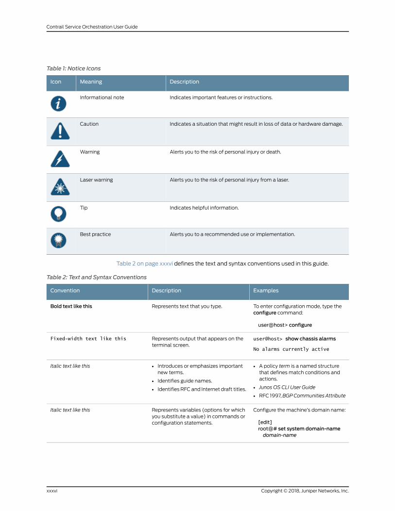
Table 1: Notice Icons
DescriptionMeaningIcon
Indicates important features or instructions.Informational note
Indicates a situation that might result in loss of data or hardware damage.Caution
Alerts you to the risk of personal injury or death.Warning
Alerts you to the risk of personal injury from a laser.Laser warning
Indicates helpful information.Tip
Alerts you to a recommended use or implementation.Best practice
Table 2 on page xxxvi defines the text and syntax conventions used in this guide.
Table 2: Text and Syntax Conventions
ExamplesDescriptionConvention
To enter configuration mode, type theconfigure command:
user@host> configure
Represents text that you type.Bold text like this
user@host> show chassis alarms
No alarms currently active
Represents output that appears on theterminal screen.
Fixed-width text like this
• A policy term is a named structurethat defines match conditions andactions.
• Junos OS CLI User Guide
• RFC 1997,BGPCommunities Attribute
• Introduces or emphasizes importantnew terms.
• Identifies guide names.
• Identifies RFC and Internet draft titles.
Italic text like this
Configure themachine’s domain name:
[edit]root@# set system domain-namedomain-name
Represents variables (options for whichyou substitute a value) in commands orconfiguration statements.
Italic text like this
Copyright © 2018, Juniper Networks, Inc.xxxvi
Contrail Service Orchestration User Guide
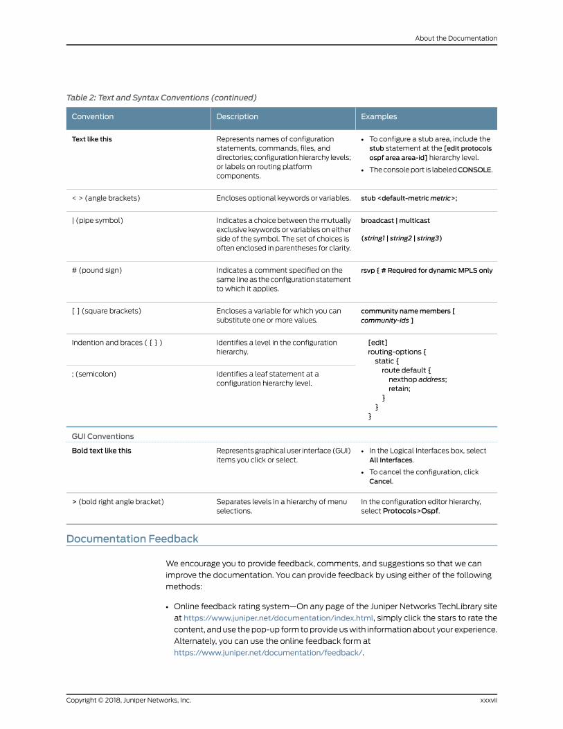
Table 2: Text and Syntax Conventions (continued)
ExamplesDescriptionConvention
• To configure a stub area, include thestub statement at the [edit protocolsospf area area-id] hierarchy level.
• Theconsoleport is labeledCONSOLE.
Represents names of configurationstatements, commands, files, anddirectories; configurationhierarchy levels;or labels on routing platformcomponents.
Text like this
stub <default-metricmetric>;Encloses optional keywords or variables.< > (angle brackets)
broadcast | multicast
(string1 | string2 | string3)
Indicates a choice between themutuallyexclusive keywords or variables on eitherside of the symbol. The set of choices isoften enclosed in parentheses for clarity.
| (pipe symbol)
rsvp { # Required for dynamicMPLS onlyIndicates a comment specified on thesame lineas theconfiguration statementto which it applies.
# (pound sign)
community namemembers [community-ids ]
Encloses a variable for which you cansubstitute one or more values.
[ ] (square brackets)
[edit]routing-options {static {route default {nexthop address;retain;
}}
}
Identifies a level in the configurationhierarchy.
Indention and braces ( { } )
Identifies a leaf statement at aconfiguration hierarchy level.
; (semicolon)
GUI Conventions
• In the Logical Interfaces box, selectAll Interfaces.
• To cancel the configuration, clickCancel.
Representsgraphicaluser interface(GUI)items you click or select.
Bold text like this
In the configuration editor hierarchy,select Protocols>Ospf.
Separates levels in a hierarchy of menuselections.
> (bold right angle bracket)
Documentation Feedback
We encourage you to provide feedback, comments, and suggestions so that we can
improve the documentation. You can provide feedback by using either of the following
methods:
• Online feedback rating system—On any page of the Juniper Networks TechLibrary site
at https://www.juniper.net/documentation/index.html, simply click the stars to rate the
content, anduse thepop-up formtoprovideuswith informationabout your experience.
Alternately, you can use the online feedback form at
https://www.juniper.net/documentation/feedback/.
xxxviiCopyright © 2018, Juniper Networks, Inc.
About the Documentation
• E-mail—Sendyourcommentsto [email protected]. Includethedocument
or topic name, URL or page number, and software version (if applicable).
Requesting Technical Support
Technical product support is available through the JuniperNetworksTechnicalAssistance
Center (JTAC). If you are a customer with an active J-Care or Partner Support Service
support contract, or are covered under warranty, and need post-sales technical support,
you can access our tools and resources online or open a case with JTAC.
• JTAC policies—For a complete understanding of our JTAC procedures and policies,
review the JTAC User Guide located at
https://www.juniper.net/us/en/local/pdf/resource-guides/7100059-en.pdf.
• Product warranties—For product warranty information, visit
https://www.juniper.net/support/warranty/.
• JTAC hours of operation—The JTAC centers have resources available 24 hours a day,
7 days a week, 365 days a year.
Self-Help Online Tools and Resources
For quick and easy problem resolution, Juniper Networks has designed an online
self-service portal called the Customer Support Center (CSC) that provides youwith the
following features:
• Find CSC offerings: https://www.juniper.net/customers/support/
• Search for known bugs: https://prsearch.juniper.net/
• Find product documentation: https://www.juniper.net/documentation/
• Find solutions and answer questions using our Knowledge Base: https://kb.juniper.net/
• Download the latest versions of software and review release notes:
https://www.juniper.net/customers/csc/software/
• Search technical bulletins for relevant hardware and software notifications:
https://kb.juniper.net/InfoCenter/
• Join and participate in the Juniper Networks Community Forum:
https://www.juniper.net/company/communities/
• Open a case online in the CSC Case Management tool: https://www.juniper.net/cm/
Toverify serviceentitlementbyproduct serial number, useourSerialNumberEntitlement
(SNE) Tool: https://entitlementsearch.juniper.net/entitlementsearch/
Opening a Casewith JTAC
You can open a case with JTAC on theWeb or by telephone.
• Use the Case Management tool in the CSC at https://www.juniper.net/cm/.
• Call 1-888-314-JTAC (1-888-314-5822 toll-free in the USA, Canada, and Mexico).
Copyright © 2018, Juniper Networks, Inc.xxxviii
Contrail Service Orchestration User Guide

For international or direct-dial options in countries without toll-free numbers, see
https://www.juniper.net/support/requesting-support.html.
xxxixCopyright © 2018, Juniper Networks, Inc.
About the Documentation

Copyright © 2018, Juniper Networks, Inc.xl
Contrail Service Orchestration User Guide
PART 1
Administration Portal
• Introduction on page 3
• Managing Objects on page 13
• Using the Dashboard on page 17
• Monitoring Alerts, Alarms, and Device Events on page 19
• Monitoring Tenants SLA Performance on page 29
• Monitoring Jobs on page 45
• Managing POPs on page 51
• Managing Devices on page 91
• Managing Device Templates on page 109
• Managing Software Images on page 125
• Configuring Network Services on page 133
• Configuring Application SLA Profiles on page 155
• Configuring Application Signatures on page 173
• Managing Tenants on page 179
• Configuring MSP Users on page 197
• Configuring Authentication on page 203
• Configuring Licenses on page 213
• Customizing the Unified Portal on page 217
• Managing Signature Database on page 221
1Copyright © 2018, Juniper Networks, Inc.

Copyright © 2018, Juniper Networks, Inc.2
Contrail Service Orchestration User Guide
CHAPTER 1
Introduction
• Unified Administration and Customer Portal Overview on page 3
• Administration Portal Overview on page 4
• Logging in to Administration Portal on page 5
• Switching the Tenant Scope on page 5
• Changing the Administration Portal Password on page 6
• Changing the Password on First Login on page 7
• Resetting the Password on page 8
• Setting Password Duration on page 9
• Extending the User Login Session on page 10
• Setting Up the Cloud CPE Centralized Deployment Model with Administration
Portal on page 10
• Setting Up the Cloud CPE Distributed Deployment Model with Administration
Portal on page 11
Unified Administration and Customer Portal Overview
Contrail Service Orchestration supports a unified portal for both service provider users
and tenant users and for the servicesmanagedand consumedby the administrators and
tenants.
The unified portal contains the features of vCPE, uCPE, and SD-WAN for both
AdministrationandCustomerportals; enforces role-basedaccess control (RBAC),which
prevents tenants from accessing administrator data; and supports different backend
authentication methods for service provider users and tenant users.
The unified portal enable service providers to deploy Juniper Networks security features
as a virtualized network function (VNF) function either in distributed or centralizedmode
or in the branch SRX Series device. This VNF provides advanced firewall and Network
Address Translation (NAT)management capabilities to end users from a single pane of
glass (SPOG) user interface, in a multitenant environment. . Service provider
administrators are able tomanage all phases of the security policy life cyclemore quickly
and intuitively, from policy creation through deployment.
3Copyright © 2018, Juniper Networks, Inc.
Firewall and NATmanagement features include policy configuration such as rule
reordering, event viewer for firewall andNATevents, alertsandalarms, logsanddashboard
widgets. All features have RBAC enforced, which enables either the MSP administrator
or the tenant administrator to configure policies for the tenant.
The unified portal also provides SD-WAN capabilities with integrated firewall, NAT
management, and device management.
RelatedDocumentation
SLA Profiles and SD-WAN Policies Overview on page 164•
• Device Images Overview on page 125
Administration Portal Overview
Administration Portal offers service providers a convenient way to set up andmanage
resources, customers, and availability of network services through a graphical user
interface (GUI).
When you use Administration Portal, you are actually creating andmanaging objects
used by the following APIs in the Cloud CPE Centralized Deployment Model and Cloud
CPE Distributed Deployment Model.
• Cloud CPE Tenant, Site, and Service Manager API, which manages customers (also
called tenants),manages customer sites, andmaps each customer’s network services
to theappropriategateway resources, suchas theLayer 2access interfacesand routing
instances.
• Identity and Access Manager API, which manages identifiers and roles for customers
and users.
• NetworkServiceOrchestrationAPI,whichmanagesnetworkservicesandcommunicates
with Contrail OpenStack, the virtualized infrastructure manager (VIM).
• Contrail OpenStack API, which manages network points of presence (POPs), service
chains, and virtual machines (VMs) that contain service chains.
You can also set up andmanage the Cloud CPE Centralized Deployment Model and
CloudCPEDistributedDeploymentModel throughAPI calls, eithermanually or fromyour
operational support systems and business support systems (OSS/BSS). This method
ismorecomplex, especially if youuseyourownOSS/BSS, inwhichcaseyoumustperform
development and integrationwork. Use of Administration Portal is particularly beneficial
for companies who require a turnkey solution and do not want to expend effort on
developing programs to set up andmanage the deployment through APIs. Even if you
plan touse your ownOSS/BSSsystems to set upandmanage theCloudCPECentralized
Deployment Model and Cloud CPE Distributed Deployment Model in a production
environment, Administration Portal can prove useful for demonstrations and trials of the
deployment.
RelatedDocumentation
Setting Up the Cloud CPE Centralized Deployment Model with Administration Portal
on page 10
•
Copyright © 2018, Juniper Networks, Inc.4
Contrail Service Orchestration User Guide
• Setting Up the Cloud CPE Distributed Deployment Model with Administration Portal
on page 11
• Logging in to Administration Portal on page 5
Logging in to Administration Portal
To start Administration Portal:
1. ReviewtheKeystoneusernameandpassword that youdefined forContrailOpenStack.
You can view these settings on the Contrail Configure and Control node in the files
/etc/contrail/keystonerc and /etc/contrail/openstackrc.
2. Using aWeb browser, access the URL for Administration Portal. The URL for
Administration Portal is https://Central-IP-Address, where the Central-IP-Address
denotes the IP address of the virtual machine (VM) that hosts the microservices for
the central POP.
For example, if the IP address of the VM is 192.0.2.1, then the URL is https://192.0.2.1.
NOTE: We recommend that you use Google Chrome Version 60 or laterto access the Contrail Service Orchestration (CSO) GUIs.
3. Log in with the username cspadmin and password that you specified for Contrail
OpenStack.
The Dashboard page appears.
NOTE: You are prompted to change the password when you login to theportal for the first time.
RelatedDocumentation
Administration Portal Overview on page 4•
• Personalizing the Unified Administration and Customer Portal on page 217
Switching the Tenant Scope
Administration Portal users can change the tenant scope from all tenants to a specific
tenant by using the tenant switcher displayed on the banner.
When you switch scope from all tenants to a specific tenant, the menu and pages
displayed are almost the same as those displayed for Customer Portal users, with some
additional actions visible to the Administration Portal users. When you switch back to
the All Tenants scope, the menu and pages for the Administration Portal are displayed.
5Copyright © 2018, Juniper Networks, Inc.
Chapter 1: Introduction
To switch from one scope to another:
• From the top right corner of the page, select the All Tenants scope to access
AdministrationPortal or selecta specific tenant (for example, aaa) toaccessCustomer
Portal. Themenuandpages forAdministrationPortal orCustomerPortal aredisplayed
based on the scope selected from the drop-down list.
RelatedDocumentation
Unified Administration and Customer Portal Overview on page 3•
• Role-Based Access Control Overview on page 197
Changing the Administration Portal Password
To change the Administration Portal password:
1. Click theadministrativeusername that is locatedat the right sideof theAdministration
Portal banner.
The drop-down list appears.
2. Click Change Password.
The Change Password page appears.
NOTE: If you change the password for Administration Portal, the newpassword is saved in Contrail and applies to other GUIs, such as NetworkService Designer.
3. Enter the current password.
4. In the New Password text box, enter your new password.
The login password that you set must conform to a particular set of requirements
such asminimum length of 6 characters, amaximum length of 21 characters, and that
includes at least one lowercase letter, one uppercase letter, an alpha-numeric
character, and a numeric character.
5. In the Confirm Password text box, enter your new password again to confirm it.
You can select the ShowPassword option to view the password.
6. ClickOK.
You are logged out of the system. To log in to Administration Portal again, youmust
use your new password. Other sessions logged in with the same username are
unaffected until the next login.
Copyright © 2018, Juniper Networks, Inc.6
Contrail Service Orchestration User Guide
RelatedDocumentation
Administration Portal Overview on page 4•
• Logging in to Administration Portal on page 5
Changing the Password on First Login
To enhance the security related to login credentials, you are prompted to change the
password when you login to the portal for the first time.
To change the password when you log in for the first time:
1. Log in to the portal with the default login credentials.
The Change Password page appears with a message that youmust change your
password for security purposes.
NOTE: The Change Password page appears only if you are logging in tothe portal for the first time.
2. Change your password following the guidelines provided in Table 3 on page 7.
3. ClickOk.
NOTE: It is mandatory to change the login password when you log in tothe portal for the first time. If you click Cancel, you are redirected to the
login page.
The login password is changed and you are logged out of the system. To log in to the
portal again, youmust use your new password.
Table 3: Fields on the Change Password Page
DescriptionField
Enter your new password.
The login password that you set must be between 6 and 21 characters long, and it must include atleast one lowercase letter, one uppercase letter, one special character, and one number.
NOTE: The password strength indicator displays the efficiency of the password that you enter. Youcannot proceed to the next step if the password strength indicator shows that the password isweak.
New Password
Reenter the password for confirmation.
You can select ShowPassword to view the password.
Confirm Password
7Copyright © 2018, Juniper Networks, Inc.
Chapter 1: Introduction
RelatedDocumentation
Logging in to Administration Portal on page 5•
• Changing the Administration Portal Password on page 6
• Resetting the Password on page 8
• Setting Password Duration on page 9
Resetting the Password
If you have forgotten your password, you can reset the password from the login screen.
NOTE: Your account is locked after five consecutive unsuccessful loginattempts.
To reset the password:
1. On the login page, click the Forgot Password link.
The Forgot Password page appears, with a message that an e-mail notification with
a verification code is sent to your e-mail address.
NOTE: The Forgot Password link appears only after you specify the
username.
2. In Verification Code, specify the verification code that you have received through an
e-mail.
NOTE: The verification code expires after a time duration of 15minutes.
3. ClickOK.
The Reset Password page appears.
4. Change your password following the guidelines provided in Table 4 on page 8.
5. ClickOK.
Your password is reset.
Table 4: Fields on the Reset Password Page
DescriptionField
Enter your username.Username
Copyright © 2018, Juniper Networks, Inc.8
Contrail Service Orchestration User Guide
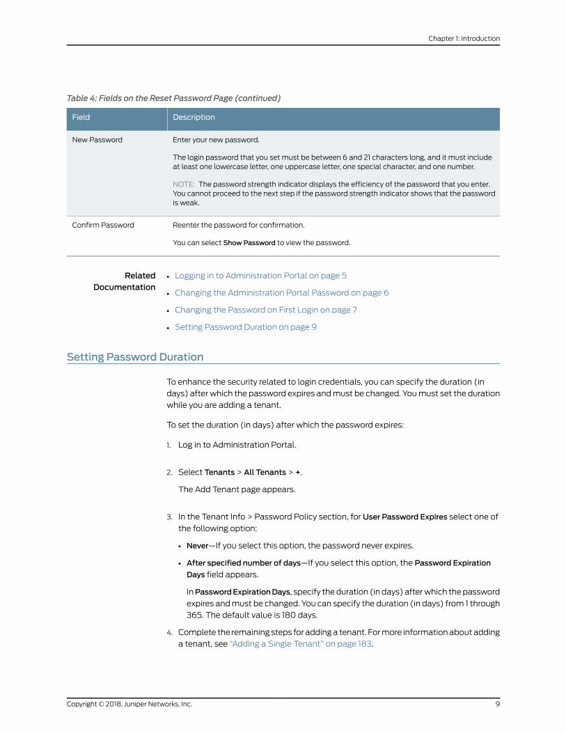
Table 4: Fields on the Reset Password Page (continued)
DescriptionField
Enter your new password.
The login password that you set must be between 6 and 21 characters long, and it must includeat least one lowercase letter, one uppercase letter, one special character, and one number.
NOTE: The password strength indicator displays the efficiency of the password that you enter.You cannot proceed to the next step if the password strength indicator shows that the passwordis weak.
New Password
Reenter the password for confirmation.
You can select ShowPassword to view the password.
Confirm Password
RelatedDocumentation
Logging in to Administration Portal on page 5•
• Changing the Administration Portal Password on page 6
• Changing the Password on First Login on page 7
• Setting Password Duration on page 9
Setting Password Duration
To enhance the security related to login credentials, you can specify the duration (in
days) after which the password expires andmust be changed. Youmust set the duration
while you are adding a tenant.
To set the duration (in days) after which the password expires:
1. Log in to Administration Portal.
2. Select Tenants > All Tenants > +.
The Add Tenant page appears.
3. In the Tenant Info > Password Policy section, for User Password Expires select one of
the following option:
• Never—If you select this option, the password never expires.
• After specified number of days—If you select this option, the Password Expiration
Days field appears.
InPasswordExpirationDays, specify theduration (in days) afterwhich thepassword
expires andmust be changed. You can specify the duration (in days) from 1 through
365. The default value is 180 days.
4. Complete the remaining steps for addinga tenant. Formore informationaboutadding
a tenant, see “Adding a Single Tenant” on page 183.
9Copyright © 2018, Juniper Networks, Inc.
Chapter 1: Introduction
If the tenant user (Tenant Administrator role or Tenant Operator role) has the password
expiration days specified, then the tenant user must change the password after the
specified duration elapses.
RelatedDocumentation
Logging in to Administration Portal on page 5•
• Changing the Administration Portal Password on page 6
• Changing the Password on First Login on page 7
• Resetting the Password on page 8
Extending the User Login Session
In the unified portal, a login session expires in 60minutes. After 55minutes, the Extend
Session page is displayed and, prompting you to enter your password. Youmust enter
your password to extend the session. The Extend Session page is displayed when the
Local authentication method is configured.
If you have logged in to the portal with SSO authentication, the Extend Session page is
displayed and you can authenticate with the external SSO server. However, the SSO
expiration is not under the control of CSO and the following can happen:
• If the external SSO session is expired, you will be authenticated in the Extend Session
page. After successful authentication, theExtendSessionpage is closedautomatically.
• If the external SSO session is not expired, the Extend Session page is closed
automatically.
To extend the login session:
1. On the Extend Session page, enter your password in the Password field. If you want
toendyour sessionandexit fromtheportal, clickCancel insteadandyouare redirected
to the Login page.
2. ClickOK.
The success message Your Session has been successfully extended is displayed.
RelatedDocumentation
Changing the Administration Portal Password on page 6•
Setting Up the Cloud CPE Centralized Deployment Model with Administration Portal
In the Cloud CPE Centralized Deployment Model, end users at a specific customer site
access most network services in a regional point of presence (POP), while accessing a
few specialist network services in the central POP.
You use the following workflow to set up the Cloud CPE Centralized Deployment Model
with Administration Portal:
Copyright © 2018, Juniper Networks, Inc.10
Contrail Service Orchestration User Guide
1. Create the POPs and associated resources. See “Creating a Single POP” on page 53
and “Importing Data for Multiple POPs” on page 64.
• Youmust create a VIM for each POP.
• You can add an MX Series router as a physical network element (PNE) to provide
a Layer 3 routing service to customer sites through use of virtual routing and
forwarding (VRF) instances.
• You add the Junos Space element management system (EMS) if you use a VNF
that requires this EMS.
2. Create customers. See “Adding a Single Tenant” on page 183 and “Importing Data for
Multiple Tenants” on page 188.
3. If you add customers one at a time, rather than importing data for multiple tenants,
create and configure sites for each customer:
• Youmust create each site individually. You can create the following sites:
• On-Premise sites—required for all customer sites. See “Creating On-Premise
Spoke Sites for SD-WAN Deployment” on page 549.
• Cloud sites—required for all service providers. See “Creating Cloud Hub Sites for
SD-WAN Deployment” on page 554.
• Data Center—Only required for a network in which users access the Internet
through the corporate VPN.
• If you configured aPNE in Step 1, then associate the PNEwith the site and configure
a VRF for each customer site. See “Configuring VRFs and PNE Details for a Site in
a Centralized Deployment” on page 580
4. Allocate network services to customers. See “Allocating a Service to Tenants” on
page 139
RelatedDocumentation
Logging in to Administration Portal on page 5•
• Administration Portal Overview on page 4
Setting Up the Cloud CPE Distributed Deployment Model with Administration Portal
In the Cloud CPE Distributed Deployment Model, end users at a specific customer site
access network services in both a regional point of presence (POP) and a central POP.
You use the following workflow to set up the Cloud CPE Distributed Deployment Model
with Administration Portal:
1. Add data for the POPs and provider edge (PE) router. See “Creating a Single POP” on
page 53 and “Importing Data for Multiple POPs” on page 64.
2. Upload images for devices used in the deployment, such as the vSRX gateway and
theNFX250platform to the central activation server. See “Uploading aDevice Image”
on page 129.
11Copyright © 2018, Juniper Networks, Inc.
Chapter 1: Introduction
3. Upload VNF images. See “Uploading a Device Image” on page 129.
4. Create customers. See “Adding a Single Tenant” on page 183 and “Importing Data for
Multiple Tenants” on page 188.
5. If you add customers one at a time, rather than importing data for multiple tenants,
create and configure sites for each customer. .
6. Allocate network services to customers. See “Allocating a Service to Tenants” on
page 139.
RelatedDocumentation
• Logging in to Administration Portal on page 5
• Administration Portal Overview on page 4
Copyright © 2018, Juniper Networks, Inc.12
Contrail Service Orchestration User Guide
CHAPTER 2
Managing Objects
• Creating Objects on page 13
• Modifying an Object on page 13
• Deleting Objects on page 14
• Viewing Object Details on page 14
• Searching for Text in an Object Data Table on page 15
• Sorting Objects on page 15
Creating Objects
You can use the create icon (+) in the top right corner of a page to create an object on
that page.
To create an object:
1. Click the + icon.
The object configuration page appears.
2. Update the configuration as needed.
See the relevant About the Objects Page topic for a description of the fields.
3. Click Upload.
The object information that you updated appears in the main page.
RelatedDocumentation
Deleting Objects on page 14•
Modifying an Object
You can use the pencil icon in the top right of a page to modify or edit an object on that
page.
13Copyright © 2018, Juniper Networks, Inc.
Tomodify an object:
1. Select the check box of the object that you want to modify, and click the pencil icon.
The object configuration page appears.
2. Update the configuration as needed.
3. Click Save.
The object information that you updated appears in the main page.
RelatedDocumentation
Deleting Objects on page 14•
Deleting Objects
You can use the delete icon (X) in the top right corner of a page to delete an object on
that page.
To delete an object:
1. Select the object that you want to delete and click the X icon.
The Confirm Delete page appears.
2. Click Yes to delete the object or No to cancel the deletion.
The object information is deleted from themain page.
RelatedDocumentation
Creating Objects on page 13•
Viewing Object Details
You can use the Detailed View page to view all the configured parameters of an object.
Only some of the configured parameters appear in the list of features on themain page.
To view details for an object:
• Right-click the object that you want to see the detailed view for and clickQuick View,
or select the object and clickMore > Details.
• Alternatively, hoverover theobjectnameandclick theDetailedView icon thatappears
before it.
TheDetailedViewpage appears showing the configuration information. See the relevant
About the Objects Page topic for a description of the fields on these pages.
Copyright © 2018, Juniper Networks, Inc.14
Contrail Service Orchestration User Guide
RelatedDocumentation
Deleting Objects on page 14•
Searching for Text in an Object Data Table
You can use the search icon in the top right corner of a page to search for text containing
letters and special characters on that page.
To search for text:
1. Enter partial text or full text of the keyword in the search bar and click the search icon.
The search results are displayed.
2. Click X next to a search keyword or click Clear All to clear the search results.
RelatedDocumentation
Creating Objects on page 13•
Sorting Objects
You can use the ShowHideColumns icon in the top right corner of a page to show or hide
objects on a page. You can also sort the objects in a page by clicking the object column.
The following options are available for sorting the objects:
• Sort text in alphabetical order.
• Sort numbers in ascending or descending order.
• Sort by date or time.
• Rearrange columns in a table.
• Increase or decrease columnwidth.
To show or hide an object:
1. Click the ShowHide Columns icon.
The objects that are relevant to the page are displayed. By default all objects are
selected and displayed on the page.
2. Select the objects that need to be displayed on the page and clear the objects that
are not required to be displayed.
The objects are displayed or hidden as per the selection.
RelatedDocumentation
• Creating Objects on page 13
15Copyright © 2018, Juniper Networks, Inc.
Chapter 2: Managing Objects

Copyright © 2018, Juniper Networks, Inc.16
Contrail Service Orchestration User Guide
CHAPTER 3
Using the Dashboard
• About the Administration Portal Dashboard on page 17
About the Administration Portal Dashboard
To access this page, click Administration Portal > Dashboard.
Each time you log in to the Administration Portal, the first thing you see is a
user-configurable dashboard that offers you a customized view of network services
through its widgets.
You can drag these widgets from the carousel at the top of your dashboard to your
workspace, where you can add, remove, and rearrange them tomeet your needs. For
example, you can configure awidget to display a graphwith the top five tenants receiving
alerts, the status of alerts, and the name of tenant sites.
The dashboard automatically adjusts the placement of the widgets to dynamically fit
on your browser windowwithout changing their order. You canmanually reorder the
widgetsusing thedraganddropoption. In addition, youcanpressandhold the topportion
of the widget to move it to a new location.
Tasks You Can Perform
You can perform the following tasks from this page:
• Customize the dashboard by adding, removing, and rearranging the widgets on a per
user basis.
• Update the dashboard or an individual widget by clicking the refresh icon.
• Show or hide widget thumbnails in the carousel by clicking SelectWidgets at the top
of the page.
• Add a widget to the dashboard by dragging the widget from the palette or thumbnail
container into the workspace.
• Delete a widget from the dashboard page by clicking the X icon in the title bar.
Field Descriptions
You can quickly view important data using the widgets at the top of your dashboard.
17Copyright © 2018, Juniper Networks, Inc.
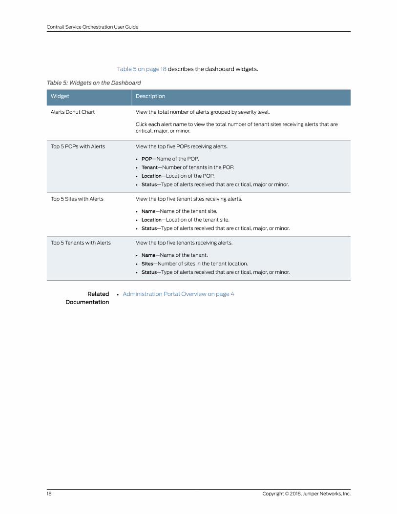
Table 5 on page 18 describes the dashboard widgets.
Table 5: Widgets on the Dashboard
DescriptionWidget
View the total number of alerts grouped by severity level.
Click each alert name to view the total number of tenant sites receiving alerts that arecritical, major, or minor.
Alerts Donut Chart
View the top five POPs receiving alerts.
• POP—Name of the POP.
• Tenant—Number of tenants in the POP.
• Location—Location of the POP.
• Status—Type of alerts received that are critical, major or minor.
Top 5 POPs with Alerts
View the top five tenant sites receiving alerts.
• Name—Name of the tenant site.
• Location—Location of the tenant site.
• Status—Type of alerts received that are critical, major, or minor.
Top 5 Sites with Alerts
View the top five tenants receiving alerts.
• Name—Name of the tenant.
• Sites—Number of sites in the tenant location.
• Status—Type of alerts received that are critical, major, or minor.
Top 5 Tenants with Alerts
RelatedDocumentation
• Administration Portal Overview on page 4
Copyright © 2018, Juniper Networks, Inc.18
Contrail Service Orchestration User Guide
CHAPTER 4
Monitoring Alerts, Alarms, and DeviceEvents
• About the Monitor Overview Page on page 19
• About the Generated Alerts Page on page 20
• About the SD-WAN Alert Definitions Page on page 21
• Creating SD-WAN Alert Definitions on page 22
• Editing and Deleting SD-WAN Alert Definitions on page 24
• About the Device Events Page on page 25
About theMonitor Overview Page
To access this page, clickMonitor > Overview.
You can use the Monitor Overview page to view information about the alarms and alerts
for tenants, POPs, connections, and sites on a geographical map. The network operator
views the alarms and alerts, and then takes the necessary actions to resolve the issues.
Tasks You Can Perform
You can perform the following tasks from this page:
• View POP details.
• View site details.
• View connections.
• View only the nodes with alerts.
Field Descriptions
Table 6 on page 20 shows the descriptions of the fields on the Monitor Overview page.
19Copyright © 2018, Juniper Networks, Inc.
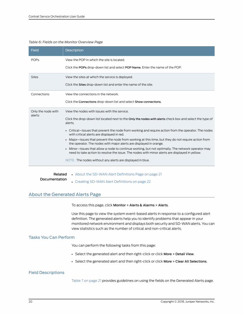
Table 6: Fields on theMonitor Overview Page
DescriptionField
View the POP in which the site is located.
Click the POPs drop-down list and select POPName. Enter the name of the POP.
POPs
View the sites at which the service is deployed.
Click the Sites drop-down list and enter the name of the site.
Sites
View the connections in the network.
Click the Connections drop-down list and select Show connections.
Connections
View the nodes with issues with the service.
Click the drop-down list located next to theOnly the nodes with alerts check box and select the type ofalerts.
• Critical—Issues that prevent the node fromworking and require action from the operator. The nodeswith critical alerts are displayed in red.
• Major—Issues that prevent the node fromworking at this time, but they do not require action fromthe operator. The nodes with major alerts are displayed in orange.
• Minor—Issues that allow a node to continue working, but not optimally. The network operator mayneed to take action to resolve the issue. The nodes with minor alerts are displayed in yellow.
NOTE: The nodes without any alerts are displayed in blue.
Only the node withalerts
RelatedDocumentation
About the SD-WAN Alert Definitions Page on page 21•
• Creating SD-WAN Alert Definitions on page 22
About the Generated Alerts Page
To access this page, clickMonitor > Alerts & Alarms > Alerts.
Use this page to view the system event-based alerts in response to a configured alert
definition. The generated alerts help you to identify problems that appear in your
monitored network environment and displays both security and SD-WANalerts. You can
view statistics such as the number of critical and non-critical alerts.
Tasks You Can Perform
You can perform the following tasks from this page:
• Select the generated alert and then right-click or clickMore > Detail View.
• Select the generated alert and then right-click or clickMore > Clear All Selections.
Field Descriptions
Table 7 on page 21 provides guidelines on using the fields on the Generated Alerts page.
Copyright © 2018, Juniper Networks, Inc.20
Contrail Service Orchestration User Guide
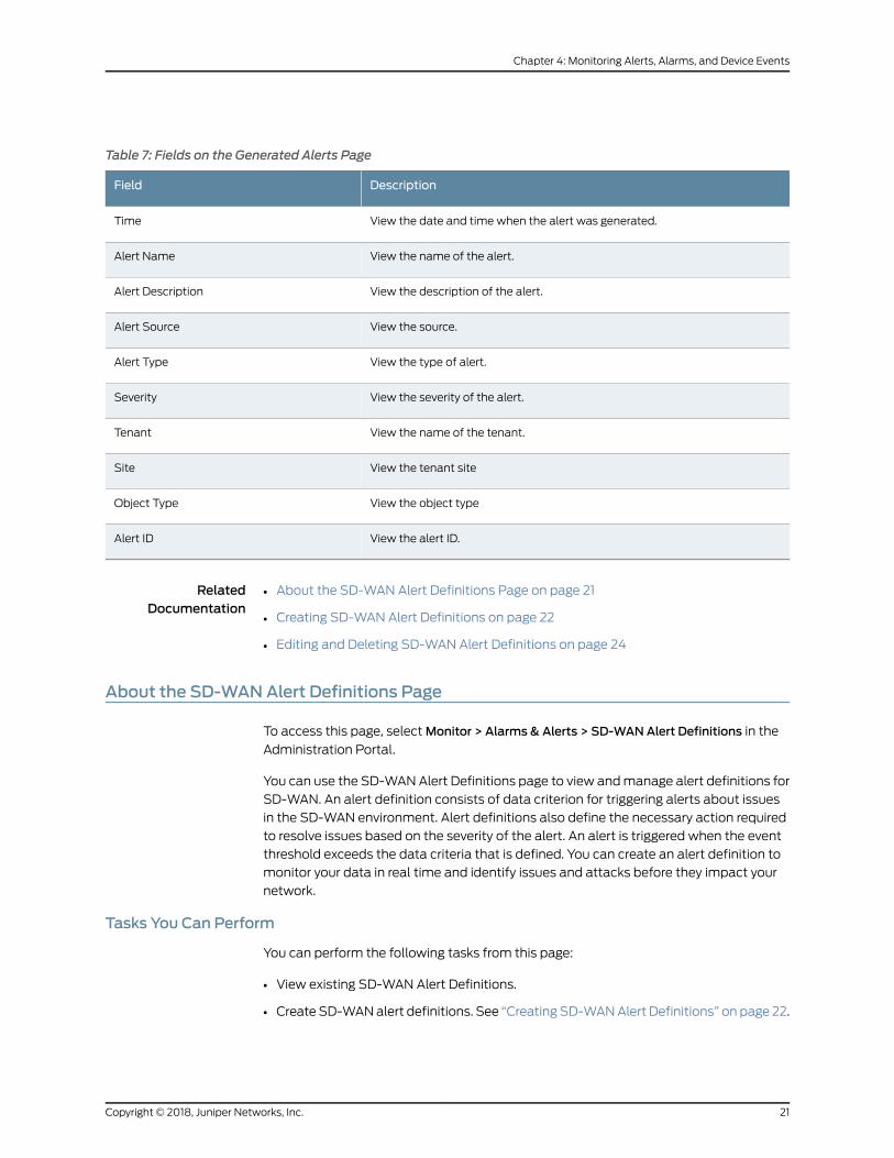
Table 7: Fields on the Generated Alerts Page
DescriptionField
View the date and time when the alert was generated.Time
View the name of the alert.Alert Name
View the description of the alert.Alert Description
View the source.Alert Source
View the type of alert.Alert Type
View the severity of the alert.Severity
View the name of the tenant.Tenant
View the tenant siteSite
View the object typeObject Type
View the alert ID.Alert ID
RelatedDocumentation
About the SD-WAN Alert Definitions Page on page 21•
• Creating SD-WAN Alert Definitions on page 22
• Editing and Deleting SD-WAN Alert Definitions on page 24
About the SD-WANAlert Definitions Page
To access this page, selectMonitor > Alarms & Alerts > SD-WANAlert Definitions in the
Administration Portal.
You can use the SD-WANAlert Definitions page to view andmanage alert definitions for
SD-WAN. An alert definition consists of data criterion for triggering alerts about issues
in the SD-WAN environment. Alert definitions also define the necessary action required
to resolve issues based on the severity of the alert. An alert is triggered when the event
threshold exceeds the data criteria that is defined. You can create an alert definition to
monitor your data in real time and identify issues and attacks before they impact your
network.
Tasks You Can Perform
You can perform the following tasks from this page:
• View existing SD-WAN Alert Definitions.
• Create SD-WANalert definitions. See “Creating SD-WANAlert Definitions” on page 22.
21Copyright © 2018, Juniper Networks, Inc.
Chapter 4: Monitoring Alerts, Alarms, and Device Events
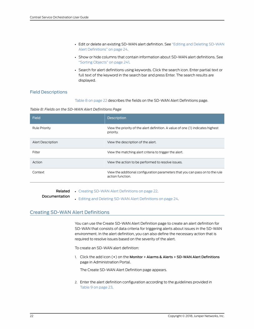
• Edit or delete an existing SD-WAN alert definition. See “Editing and Deleting SD-WAN
Alert Definitions” on page 24.
• Show or hide columns that contain information about SD-WAN alert definitions. See
“Sorting Objects” on page 241.
• Search for alert definitions using keywords. Click the search icon. Enter partial text or
full text of the keyword in the search bar and press Enter. The search results are
displayed.
Field Descriptions
Table 8 on page 22 describes the fields on the SD-WAN Alert Definitions page.
Table 8: Fields on the SD-WANAlert Definitions Page
DescriptionField
View the priority of the alert definition. A value of one (1) indicates highestpriority.
Rule Priority
View the description of the alert.Alert Description
View thematching alert criteria to trigger the alert.Filter
View the action to be performed to resolve issues.Action
View the additional configuration parameters that you can pass on to the ruleaction function.
Context
RelatedDocumentation
Creating SD-WAN Alert Definitions on page 22.•
• Editing and Deleting SD-WAN Alert Definitions on page 24.
Creating SD-WANAlert Definitions
You can use the Create SD-WAN Alert Definition page to create an alert definition for
SD-WAN that consists of data criteria for triggering alerts about issues in the SD-WAN
environment. In the alert definition, you can also define the necessary action that is
required to resolve issues based on the severity of the alert.
To create an SD-WAN alert definition:
1. Click the add icon (+) on theMonitor > Alarms & Alerts > SD-WANAlert Definitions
page in Administration Portal.
The Create SD-WAN Alert Definition page appears.
2. Enter the alert definition configuration according to the guidelines provided in
Table 9 on page 23.
Copyright © 2018, Juniper Networks, Inc.22
Contrail Service Orchestration User Guide
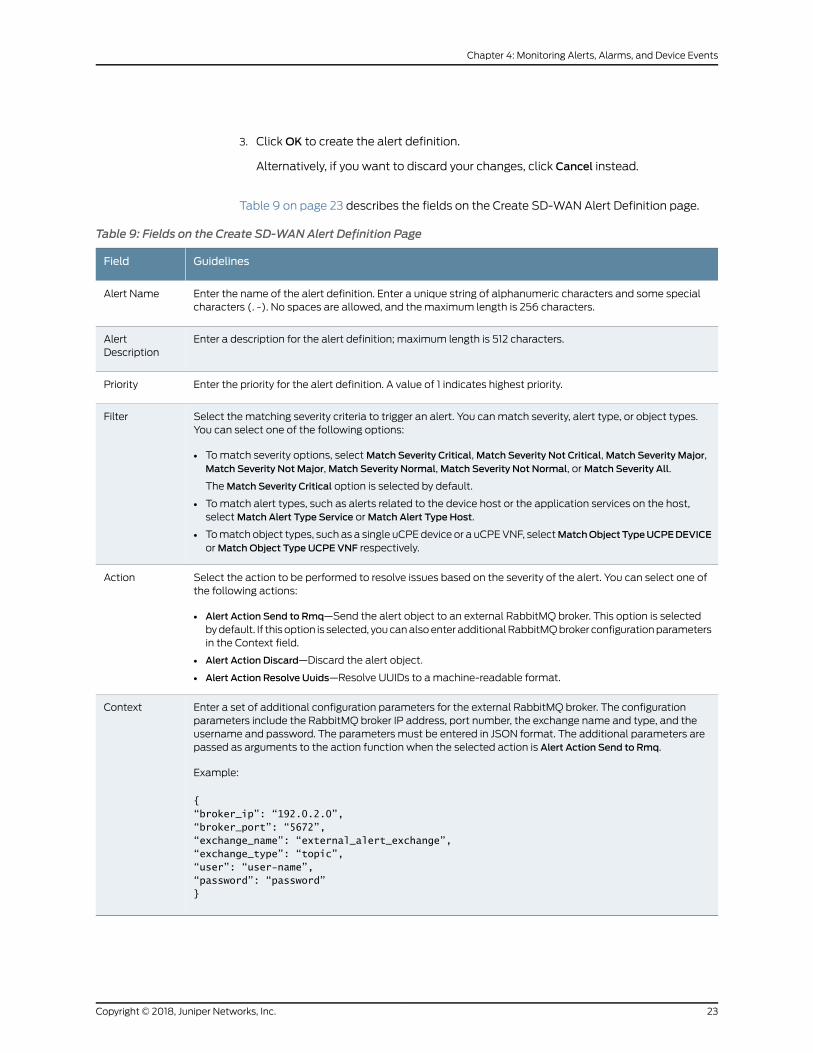
3. ClickOK to create the alert definition.
Alternatively, if you want to discard your changes, click Cancel instead.
Table 9 on page 23 describes the fields on the Create SD-WAN Alert Definition page.
Table 9: Fields on the Create SD-WANAlert Definition Page
GuidelinesField
Enter the name of the alert definition. Enter a unique string of alphanumeric characters and some specialcharacters (. -). No spaces are allowed, and themaximum length is 256 characters.
Alert Name
Enter a description for the alert definition; maximum length is 512 characters.AlertDescription
Enter the priority for the alert definition. A value of 1 indicates highest priority.Priority
Select the matching severity criteria to trigger an alert. You canmatch severity, alert type, or object types.You can select one of the following options:
• Tomatch severity options, selectMatch Severity Critical,Match Severity Not Critical,Match Severity Major,Match Severity Not Major,Match Severity Normal,Match Severity Not Normal, orMatch Severity All.
TheMatch Severity Critical option is selected by default.
• Tomatch alert types, such as alerts related to the device host or the application services on the host,selectMatch Alert Type Service orMatch Alert Type Host.
• Tomatch object types, such as a single uCPEdevice or a uCPEVNF, selectMatchObjectTypeUCPEDEVICEorMatch Object Type UCPE VNF respectively.
Filter
Select the action to be performed to resolve issues based on the severity of the alert. You can select one ofthe following actions:
• Alert Action Send to Rmq—Send the alert object to an external RabbitMQ broker. This option is selectedbydefault. If this option is selected, youcanalsoenter additionalRabbitMQbroker configurationparametersin the Context field.
• Alert Action Discard—Discard the alert object.
• Alert Action Resolve Uuids—Resolve UUIDs to amachine-readable format.
Action
Enter a set of additional configuration parameters for the external RabbitMQ broker. The configurationparameters include the RabbitMQ broker IP address, port number, the exchange name and type, and theusername and password. The parameters must be entered in JSON format. The additional parameters arepassed as arguments to the action function when the selected action is Alert Action Send to Rmq.
Example:
{“broker_ip”: “192.0.2.0”,“broker_port”: “5672”,“exchange_name”: “external_alert_exchange”,“exchange_type”: “topic”,“user”: “user-name”,“password”: “password”}
Context
23Copyright © 2018, Juniper Networks, Inc.
Chapter 4: Monitoring Alerts, Alarms, and Device Events
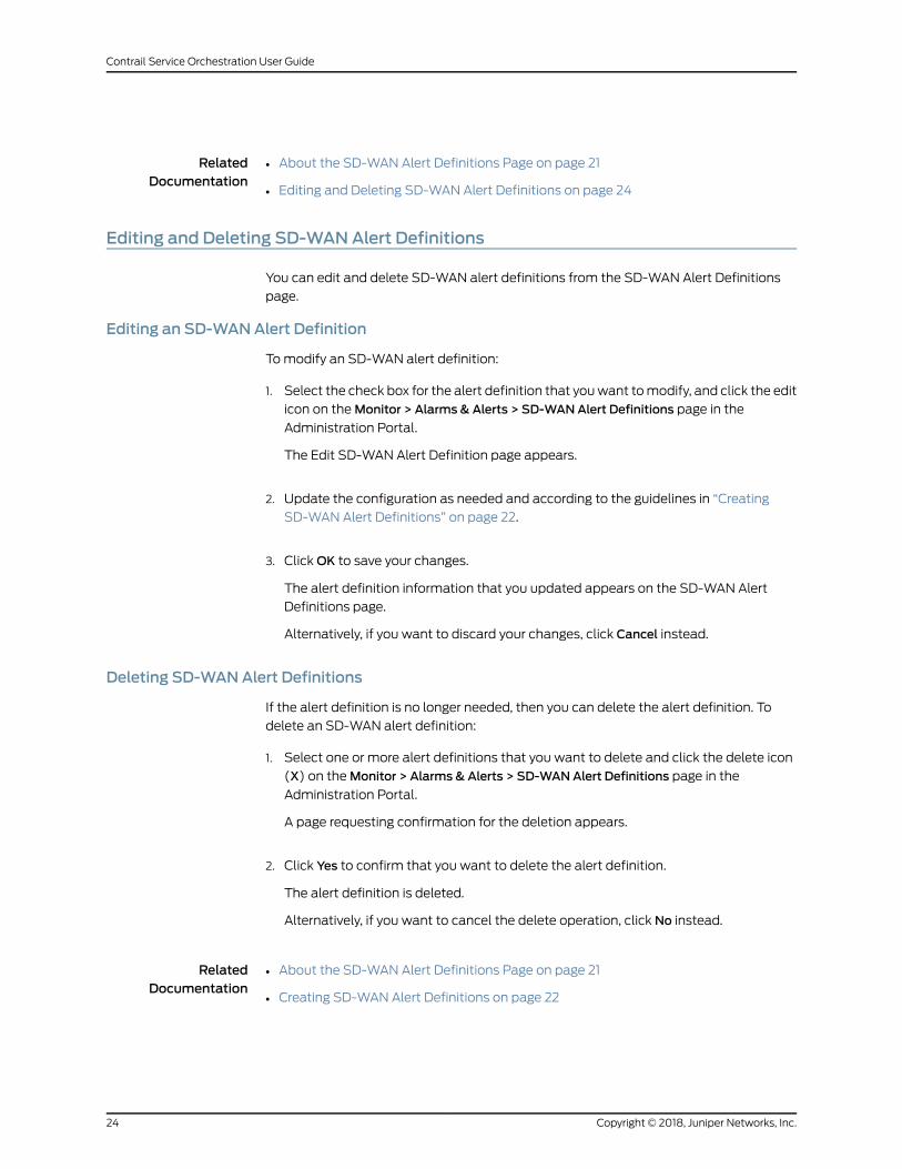
RelatedDocumentation
About the SD-WAN Alert Definitions Page on page 21•
• Editing and Deleting SD-WAN Alert Definitions on page 24
Editing and Deleting SD-WANAlert Definitions
You can edit and delete SD-WAN alert definitions from the SD-WAN Alert Definitions
page.
Editing an SD-WANAlert Definition
Tomodify an SD-WAN alert definition:
1. Select the check box for the alert definition that youwant tomodify, and click the edit
icon on theMonitor > Alarms & Alerts > SD-WANAlert Definitions page in the
Administration Portal.
The Edit SD-WAN Alert Definition page appears.
2. Update the configuration as needed and according to the guidelines in “Creating
SD-WAN Alert Definitions” on page 22.
3. ClickOK to save your changes.
The alert definition information that you updated appears on the SD-WAN Alert
Definitions page.
Alternatively, if you want to discard your changes, click Cancel instead.
Deleting SD-WANAlert Definitions
If the alert definition is no longer needed, then you can delete the alert definition. To
delete an SD-WAN alert definition:
1. Select one or more alert definitions that you want to delete and click the delete icon
(X) on theMonitor > Alarms & Alerts > SD-WANAlert Definitions page in the
Administration Portal.
A page requesting confirmation for the deletion appears.
2. Click Yes to confirm that you want to delete the alert definition.
The alert definition is deleted.
Alternatively, if you want to cancel the delete operation, click No instead.
RelatedDocumentation
About the SD-WAN Alert Definitions Page on page 21•
• Creating SD-WAN Alert Definitions on page 22
Copyright © 2018, Juniper Networks, Inc.24
Contrail Service Orchestration User Guide
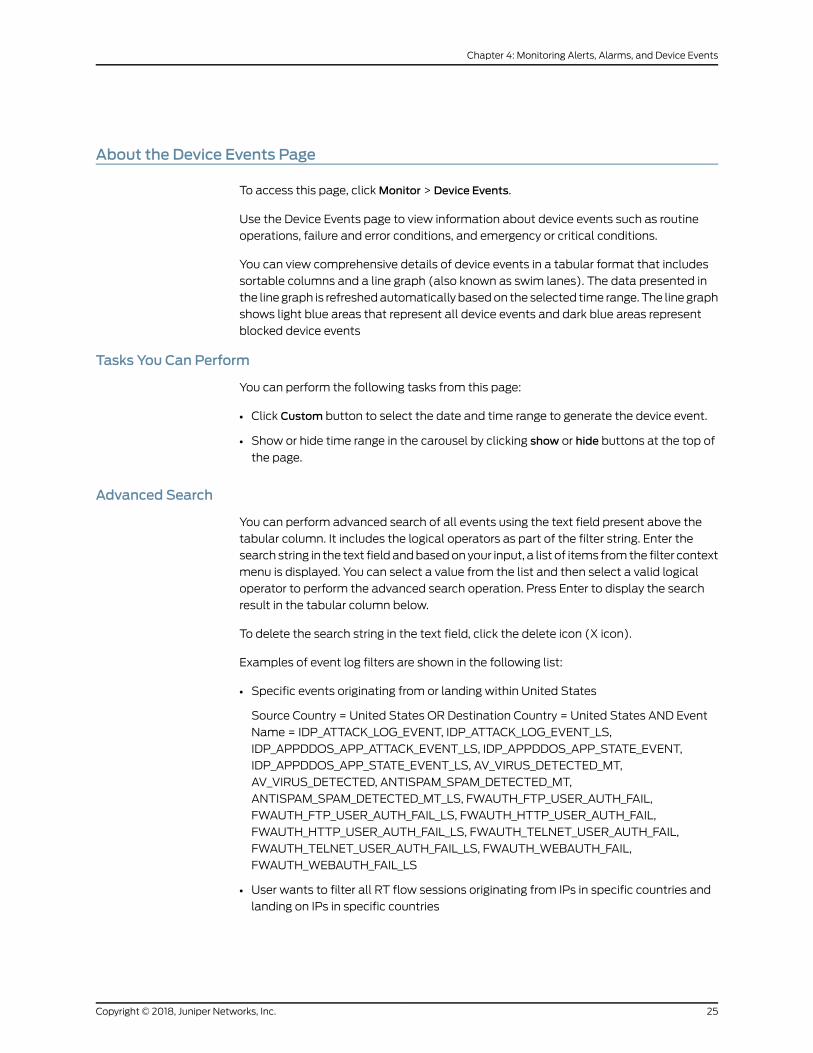
About the Device Events Page
To access this page, clickMonitor > Device Events.
Use the Device Events page to view information about device events such as routine
operations, failure and error conditions, and emergency or critical conditions.
You can view comprehensive details of device events in a tabular format that includes
sortable columns and a line graph (also known as swim lanes). The data presented in
the line graph is refreshedautomatically basedon the selected time range. The line graph
shows light blue areas that represent all device events and dark blue areas represent
blocked device events
Tasks You Can Perform
You can perform the following tasks from this page:
• Click Custom button to select the date and time range to generate the device event.
• Show or hide time range in the carousel by clicking show or hide buttons at the top of
the page.
Advanced Search
You can perform advanced search of all events using the text field present above the
tabular column. It includes the logical operators as part of the filter string. Enter the
search string in the text field andbasedon your input, a list of items from the filter context
menu is displayed. You can select a value from the list and then select a valid logical
operator to perform the advanced search operation. Press Enter to display the search
result in the tabular column below.
To delete the search string in the text field, click the delete icon (X icon).
Examples of event log filters are shown in the following list:
• Specific events originating from or landing within United States
Source Country = United States OR Destination Country = United States AND Event
Name = IDP_ATTACK_LOG_EVENT, IDP_ATTACK_LOG_EVENT_LS,
IDP_APPDDOS_APP_ATTACK_EVENT_LS, IDP_APPDDOS_APP_STATE_EVENT,
IDP_APPDDOS_APP_STATE_EVENT_LS, AV_VIRUS_DETECTED_MT,
AV_VIRUS_DETECTED, ANTISPAM_SPAM_DETECTED_MT,
ANTISPAM_SPAM_DETECTED_MT_LS, FWAUTH_FTP_USER_AUTH_FAIL,
FWAUTH_FTP_USER_AUTH_FAIL_LS, FWAUTH_HTTP_USER_AUTH_FAIL,
FWAUTH_HTTP_USER_AUTH_FAIL_LS, FWAUTH_TELNET_USER_AUTH_FAIL,
FWAUTH_TELNET_USER_AUTH_FAIL_LS, FWAUTH_WEBAUTH_FAIL,
FWAUTH_WEBAUTH_FAIL_LS
• User wants to filter all RT flow sessions originating from IPs in specific countries and
landing on IPs in specific countries
25Copyright © 2018, Juniper Networks, Inc.
Chapter 4: Monitoring Alerts, Alarms, and Device Events
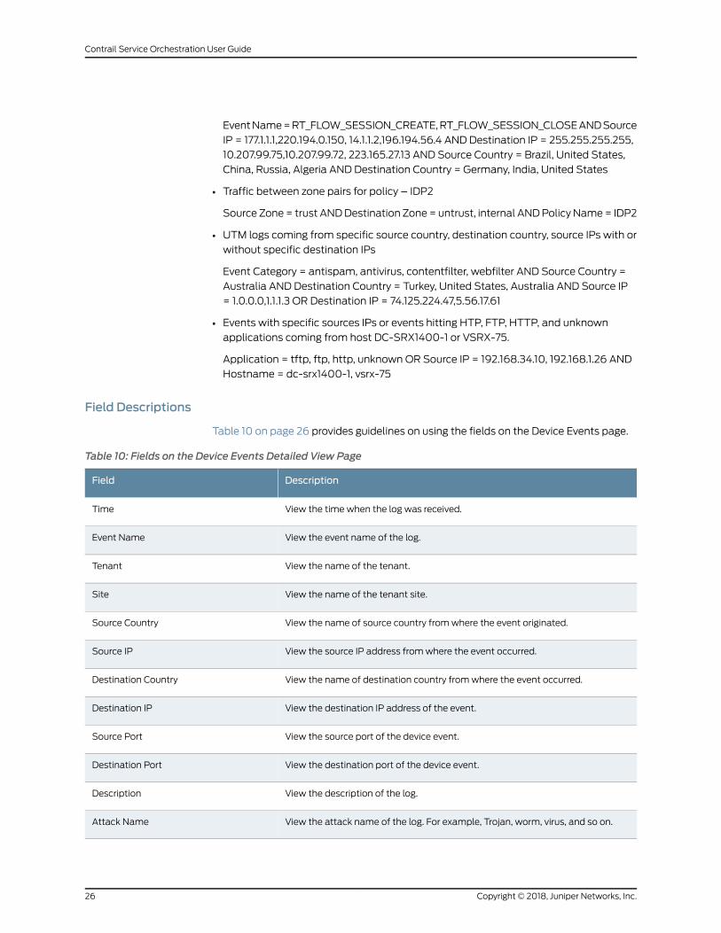
EventName=RT_FLOW_SESSION_CREATE,RT_FLOW_SESSION_CLOSEANDSource
IP = 177.1.1.1,220.194.0.150, 14.1.1.2,196.194.56.4 AND Destination IP = 255.255.255.255,
10.207.99.75,10.207.99.72, 223.165.27.13 AND Source Country = Brazil, United States,
China, Russia, Algeria AND Destination Country = Germany, India, United States
• Traffic between zone pairs for policy – IDP2
Source Zone= trust ANDDestination Zone= untrust, internal ANDPolicy Name= IDP2
• UTM logs coming from specific source country, destination country, source IPs with or
without specific destination IPs
Event Category = antispam, antivirus, contentfilter, webfilter AND Source Country =
Australia AND Destination Country = Turkey, United States, Australia AND Source IP
= 1.0.0.0,1.1.1.3 OR Destination IP = 74.125.224.47,5.56.17.61
• Events with specific sources IPs or events hitting HTP, FTP, HTTP, and unknown
applications coming from host DC-SRX1400-1 or VSRX-75.
Application = tftp, ftp, http, unknown OR Source IP = 192.168.34.10, 192.168.1.26 AND
Hostname = dc-srx1400-1, vsrx-75
Field Descriptions
Table 10 on page 26 provides guidelines on using the fields on the Device Events page.
Table 10: Fields on the Device Events Detailed View Page
DescriptionField
View the time when the log was received.Time
View the event name of the log.Event Name
View the name of the tenant.Tenant
View the name of the tenant site.Site
View the name of source country fromwhere the event originated.Source Country
View the source IP address fromwhere the event occurred.Source IP
View the name of destination country fromwhere the event occurred.Destination Country
View the destination IP address of the event.Destination IP
View the source port of the device event.Source Port
View the destination port of the device event.Destination Port
View the description of the log.Description
View the attack name of the log. For example, Trojan, worm, virus, and so on.Attack Name
Copyright © 2018, Juniper Networks, Inc.26
Contrail Service Orchestration User Guide
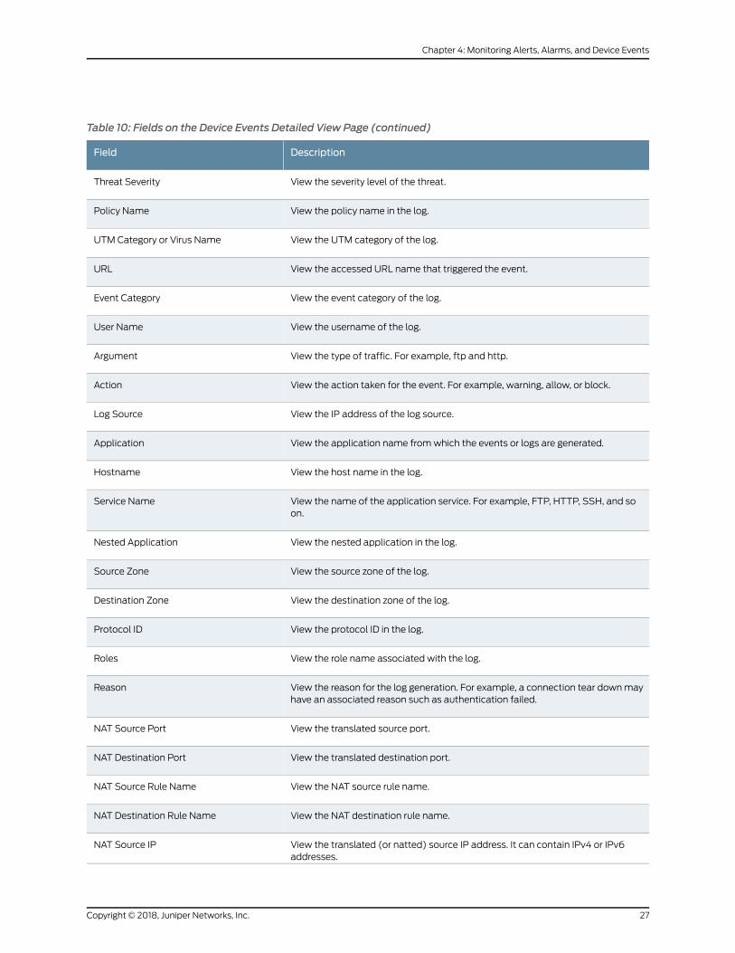
Table 10: Fields on the Device Events Detailed View Page (continued)
DescriptionField
View the severity level of the threat.Threat Severity
View the policy name in the log.Policy Name
View the UTM category of the log.UTM Category or Virus Name
View the accessed URL name that triggered the event.URL
View the event category of the log.Event Category
View the username of the log.User Name
View the type of traffic. For example, ftp and http.Argument
View the action taken for the event. For example, warning, allow, or block.Action
View the IP address of the log source.Log Source
View the application name fromwhich the events or logs are generated.Application
View the host name in the log.Hostname
View the name of the application service. For example, FTP, HTTP, SSH, and soon.
Service Name
View the nested application in the log.Nested Application
View the source zone of the log.Source Zone
View the destination zone of the log.Destination Zone
View the protocol ID in the log.Protocol ID
View the role name associated with the log.Roles
View the reason for the log generation. For example, a connection tear downmayhave an associated reason such as authentication failed.
Reason
View the translated source port.NAT Source Port
View the translated destination port.NAT Destination Port
View the NAT source rule name.NAT Source Rule Name
View the NAT destination rule name.NAT Destination Rule Name
View the translated (or natted) source IP address. It can contain IPv4 or IPv6addresses.
NAT Source IP
27Copyright © 2018, Juniper Networks, Inc.
Chapter 4: Monitoring Alerts, Alarms, and Device Events
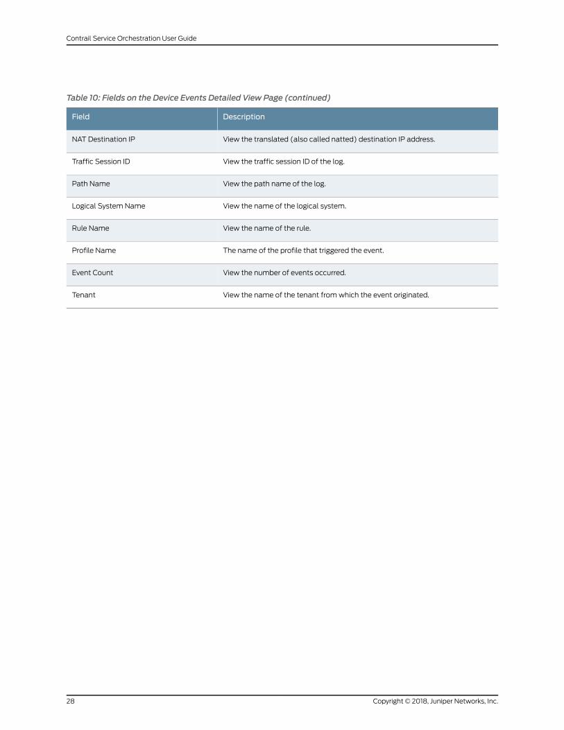
Table 10: Fields on the Device Events Detailed View Page (continued)
DescriptionField
View the translated (also called natted) destination IP address.NAT Destination IP
View the traffic session ID of the log.Traffic Session ID
View the path name of the log.Path Name
View the name of the logical system.Logical System Name
View the name of the rule.Rule Name
The name of the profile that triggered the event.Profile Name
View the number of events occurred.Event Count
View the name of the tenant fromwhich the event originated.Tenant
Copyright © 2018, Juniper Networks, Inc.28
Contrail Service Orchestration User Guide
CHAPTER 5
Monitoring Tenants SLA Performance
• Multidepartment CPE Device Support on page 29
• About the SLA Performance of All Tenants Page on page 30
• About the SLA Performance of a Single Tenant Page on page 32
• Monitoring Application-Level SLA Performance for real time-optimized
SD-WAN on page 36
• Viewing the SLA Performance of a Site on page 37
• Viewing the SLA Performance of an Application or Application Group on page 41
• Understanding SLA Performance Score for Applications, Links, Sites, and
Tenants on page 42
Multidepartment CPE Device Support
Multitenancy enables a single NFX Series device to bemapped to serve across multiple
departments within a single tenant. Each department has its own Layer 3 VPN and all
Layer 3 VPNs are carried over to the hub using a shared overlay. The traffic is segregated
to each department. A single overlay of IPsec or generic routing encapsulation (GRE)
tunnels is used to carry all department traffic from the site through MPLS-based traffic
separation.
Multitenancy is acost-effectiveapproachwhere thecostof adeviceand itsmaintenance
is sharedamongmultipledepartmentsacrossa tenant.Withmultitenantdevice support,
a dedicated share of the device is allocated to each department, and the data is kept
private from the other tenants that access the same device.
NOTE: Only users with the Tenant Administrator role have access to theCustomer Portal GUI.
The tenant administrator can perform the following tasks:
• Manage andmonitor all policies and dashboards for all departments.
• Manage applications in the dashboard for each tenant.
• Create SD-WAN and security policies for each tenant andmonitor the dashboard at
the site level or at the department level.
29Copyright © 2018, Juniper Networks, Inc.
• View or select SD-WAN or security services on the shared CPE device through the
management portal.
• View the shared CPE device and its services and networks even though theWAN links
might be shared bymultiple departments.
The service provider administrator can see all departments within the CPE device and
activate the device.
RelatedDocumentation
About the SLA Performance of a Single Tenant Page on page 283•
• Viewing the SLA Performance of a Site on page 285
About the SLA Performance of All Tenants Page
To access this page, selectMonitor > Tenants SLA Performance in the Administration
Portal.
You can use the Tenants SLA Performance page to view the SLA performance of all
tenants. This page displays the list of tenants with low, medium, and high SLA
performance during a specified time range. By default, the data is shown for the previous
one day. You can change the time range for which the data is displayed. Tenants with
low andmedium SLA performance are grouped together. The SLA performance
classification is done based on the Performance Threshold value you set. You can
customize the view by selecting the card or grid view.
Tasks You Can Perform
You can perform the following tasks from this page:
• Specify performance threshold values based on which tenants can be classified as
tenants with low, medium, or high SLA performance.
• View the SLA performance of all tenants that have low or medium SLA performance
in the specified time period.
• View the SLA performance of all tenants that have high SLA performance in the
specified time period.
• Select grid or card view for tenant SLA performance.
Select the Card view or the Grid view at the top right of the page to switch between
views. By default, the card view is selected.
• You can customize the time range to view the SLA performance of all tenants.
Select the time range for which you want to view SLA performance. You can choose
from Previous 1 hour, Previous 1 day, Previous 1 week, Previous 1 month, and Custom.
For custom time, youmust enter from and to dates in MM/DD/YYYY format and the
time in HH:MM:SS format. By default, Previous 1 day is selected.
Field Descriptions
Table 11 on page 31 describes the fields on the Tenants SLA Performance page.
Copyright © 2018, Juniper Networks, Inc.30
Contrail Service Orchestration User Guide

Table 11: Fields on the Tenants SLA Performance Page
DescriptionField
Select the time range forwhichyouwant toviewtheSLAperformance.Youcanchoose fromPrevious1 hour, Previous 1 day, Previous 1 week, Previous 1 month, and Custom. For custom time, youmustenter from and to dates in MM/DD/YYYY format and the time in HH:MM:SS format. By default,Previous 1 day is selected.
Time range
Select the view in which you want to display the SLA performance. You can choose between cardand grid views. By default, card view is selected.
View
Specify the performance threshold, in percentage, based on which tenants can be classified astenants with low, medium, or high SLA performance.
To set the performance threshold, clickMore > Performance Threshold. From the PerformanceThreshold dialog box, move the slider button to set the low and high thresholds.
Tenants that have a performance score below the low threshold are marked as having low SLAperformanceand tenants thatexceed thehigh thresholdaremarkedashavinghighSLAperformance.Tenants that have a performance score between the lowand high are considered as havingmediumSLA performance.
Performance Threshold
View tenants that have low andmediumSLA performance in the selected time period. The low andmedium performance classification is done based on the performance threshold you specify.
Click each tenant to view information about the SLA performance of the sites in the tenant. See“About the SLA Performance of a Single Tenant Page” on page 32.
Tenants with Low andMedium Performance
View the tenants that have high SLA performance in the selected time range.
Click each tenant to view information about the SLA performance of the sites in the tenant. See“About the SLA Performance of a Single Tenant Page” on page 32.
Tenants with HighPerformance
Table 12 on page 31 describes the fields in the card and grid views.
Table 12: Fields on the Tenants SLA Performance Page
DescriptionViewField
Name of the tenant.Card and GridTenant name
Number of sites associated with the tenant.Card and GridSites
Showswhether AppQoE is enabled or not. AppQoE is enabled onlywhenthe SD-WANmode is set to Real time-Optimized.
Card and GridAppQoE Function
Displays theSLAperformancescoreonascaleof 100.Scores that exceedthe high performance threshold are displayed in green. Scores that arebelow the low performance threshold are displayed in red, and themediumscores thatarebetweenthe lowandhighperformancethresholdare displayed in orange. For information about SLA performance score,see “UnderstandingSLAPerformanceScore forApplications, Links,Sites,and Tenants” on page 42.
Card and GridSLA Performance
31Copyright © 2018, Juniper Networks, Inc.
Chapter 5: Monitoring Tenants SLA Performance
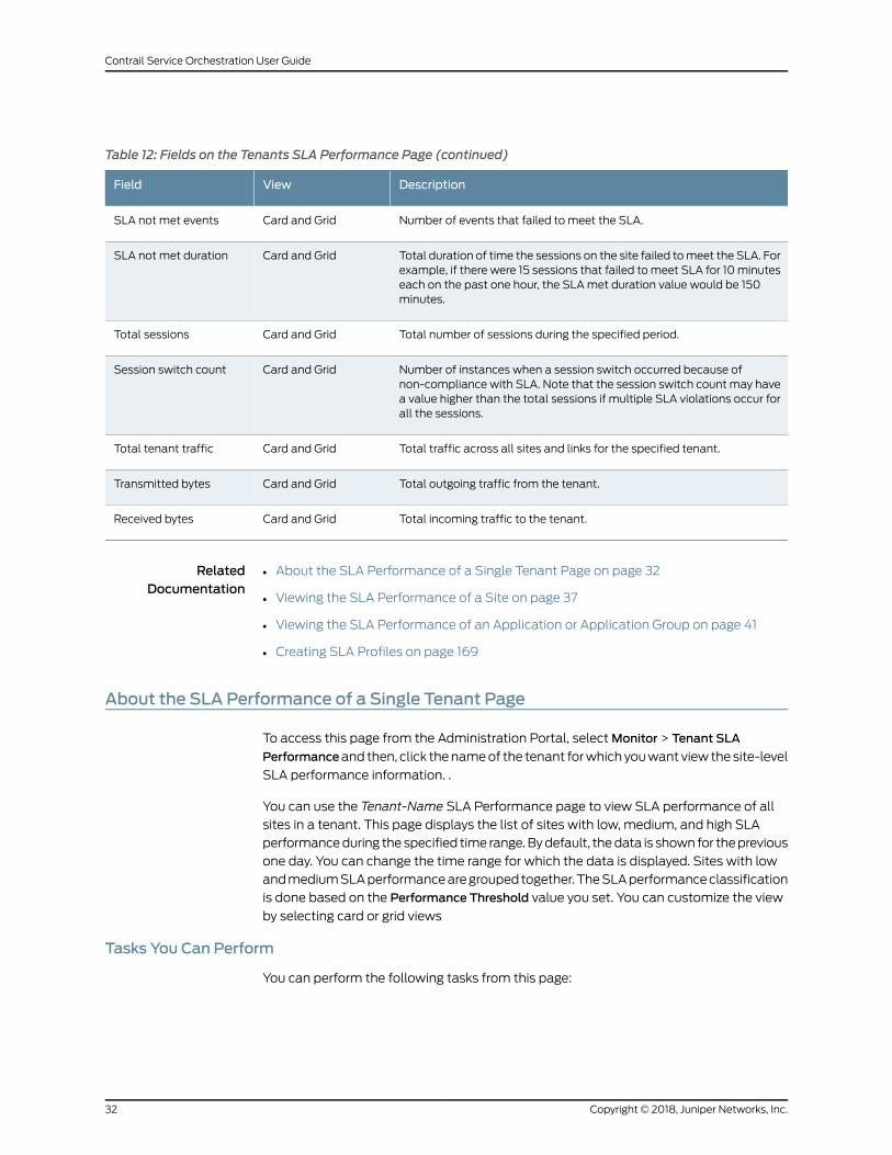
Table 12: Fields on the Tenants SLA Performance Page (continued)
DescriptionViewField
Number of events that failed to meet the SLA.Card and GridSLA not met events
Total duration of time the sessions on the site failed tomeet the SLA. Forexample, if there were 15 sessions that failed tomeet SLA for 10minuteseach on the past one hour, the SLAmet duration value would be 150minutes.
Card and GridSLA not met duration
Total number of sessions during the specified period.Card and GridTotal sessions
Number of instances when a session switch occurred because ofnon-compliance with SLA. Note that the session switch count may havea value higher than the total sessions if multiple SLA violations occur forall the sessions.
Card and GridSession switch count
Total traffic across all sites and links for the specified tenant.Card and GridTotal tenant traffic
Total outgoing traffic from the tenant.Card and GridTransmitted bytes
Total incoming traffic to the tenant.Card and GridReceived bytes
RelatedDocumentation
About the SLA Performance of a Single Tenant Page on page 32•
• Viewing the SLA Performance of a Site on page 37
• Viewing the SLA Performance of an Application or Application Group on page 41
• Creating SLA Profiles on page 169
About the SLA Performance of a Single Tenant Page
To access this page from the Administration Portal, selectMonitor > Tenant SLA
Performanceand then, click thenameof the tenant forwhich youwant view thesite-level
SLA performance information. .
You can use the Tenant-Name SLA Performance page to view SLA performance of all
sites in a tenant. This page displays the list of sites with low, medium, and high SLA
performanceduring thespecified time range.Bydefault, thedata is shown for theprevious
one day. You can change the time range for which the data is displayed. Sites with low
andmediumSLAperformancearegroupedtogether.TheSLAperformanceclassification
is done based on the Performance Threshold value you set. You can customize the view
by selecting card or grid views
Tasks You Can Perform
You can perform the following tasks from this page:
Copyright © 2018, Juniper Networks, Inc.32
Contrail Service Orchestration User Guide
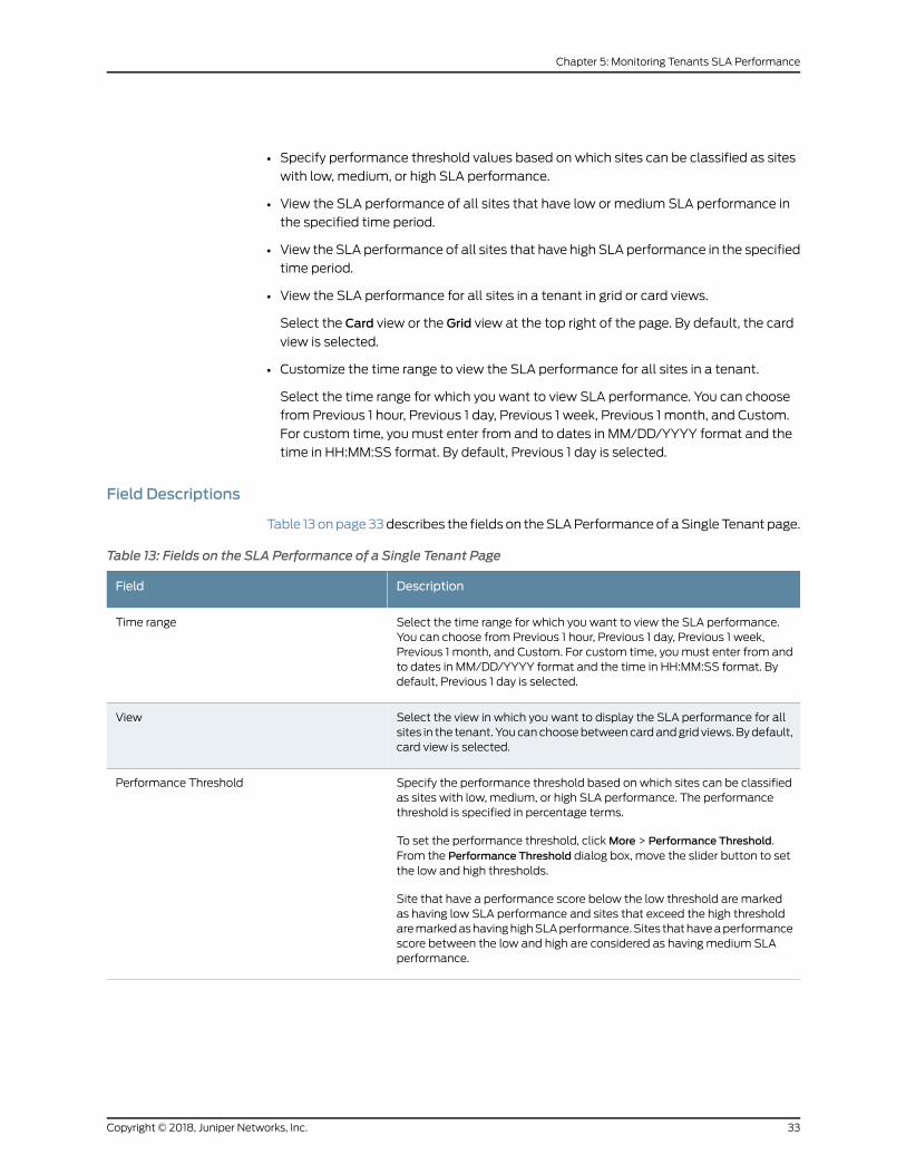
• Specify performance threshold values based on which sites can be classified as sites
with low, medium, or high SLA performance.
• View the SLA performance of all sites that have low or medium SLA performance in
the specified time period.
• View the SLA performance of all sites that have high SLA performance in the specified
time period.
• View the SLA performance for all sites in a tenant in grid or card views.
Select the Card view or the Grid view at the top right of the page. By default, the card
view is selected.
• Customize the time range to view the SLA performance for all sites in a tenant.
Select the time range for which you want to view SLA performance. You can choose
from Previous 1 hour, Previous 1 day, Previous 1 week, Previous 1 month, and Custom.
For custom time, youmust enter from and to dates in MM/DD/YYYY format and the
time in HH:MM:SS format. By default, Previous 1 day is selected.
Field Descriptions
Table 13 onpage33describes the fields on theSLAPerformanceof aSingle Tenant page.
Table 13: Fields on the SLA Performance of a Single Tenant Page
DescriptionField
Select the time range for which you want to view the SLA performance.You can choose from Previous 1 hour, Previous 1 day, Previous 1 week,Previous 1 month, and Custom. For custom time, youmust enter from andto dates in MM/DD/YYYY format and the time in HH:MM:SS format. Bydefault, Previous 1 day is selected.
Time range
Select the view in which you want to display the SLA performance for allsites in the tenant. Youcanchoosebetweencardandgrid views.Bydefault,card view is selected.
View
Specify the performance threshold based on which sites can be classifiedas sites with low, medium, or high SLA performance. The performancethreshold is specified in percentage terms.
To set the performance threshold, clickMore > Performance Threshold.From the Performance Threshold dialog box, move the slider button to setthe low and high thresholds.
Site that have a performance score below the low threshold are markedas having low SLA performance and sites that exceed the high thresholdaremarkedashavinghighSLAperformance.Sites thathaveaperformancescore between the low and high are considered as having medium SLAperformance.
Performance Threshold
33Copyright © 2018, Juniper Networks, Inc.
Chapter 5: Monitoring Tenants SLA Performance
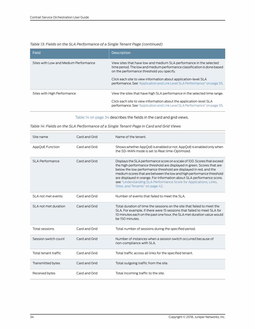
Table 13: Fields on the SLA Performance of a Single Tenant Page (continued)
DescriptionField
View sites that have low andmedium SLA performance in the selectedtimeperiod.The lowandmediumperformanceclassification isdonebasedon the performance threshold you specify.
Click each site to view information about application-level SLAperformance.See “ApplicationandLinkLevelSLAPerformance”onpage35.
Sites with Low and Medium Performance
View the sites that have high SLA performance in the selected time range.
Click each site to view information about the application-level SLAperformance.See “ApplicationandLinkLevelSLAPerformance”onpage35.
Sites with High Performance
Table 14 on page 34 describes the fields in the card and grid views.
Table 14: Fields on the SLA Performance of a Single Tenant Page in Card and Grid Views
Name of the tenant.Card and GridSite name
ShowswhetherAppQoE isenabledornot.AppQoE isenabledonlywhenthe SD-WANmode is set to Real time-Optimized.
Card and GridAppQoE Function
Displays theSLAperformancescoreonascaleof 100.Scores thatexceedthe high performance threshold are displayed in green. Scores that arebelow the low performance threshold are displayed in red, and themediumscores thatarebetweenthe lowandhighperformance thresholdare displayed in orange. For information about SLA performance score,see “Understanding SLA Performance Score for Applications, Links,Sites, and Tenants” on page 42.
Card and GridSLA Performance
Number of events that failed to meet the SLA.Card and GridSLA not met events
Total duration of time the sessions on the site that failed to meet theSLA. For example, if there were 15 sessions that failed to meet SLA for10minutes eachon thepast onehour, theSLAmet duration valuewouldbe 150minutes.
Card and GridSLA not met duration
Total number of sessions during the specified period.Card and GridTotal sessions
Number of instances when a session switch occurred because ofnon-compliance with SLA.
Card and GridSession switch count
Total traffic across all links for the specified tenant.Card and GridTotal tenant traffic
Total outgoing traffic from the site.Card and GridTransmitted bytes
Total incoming traffic to the site.Card and GridReceived bytes
Copyright © 2018, Juniper Networks, Inc.34
Contrail Service Orchestration User Guide
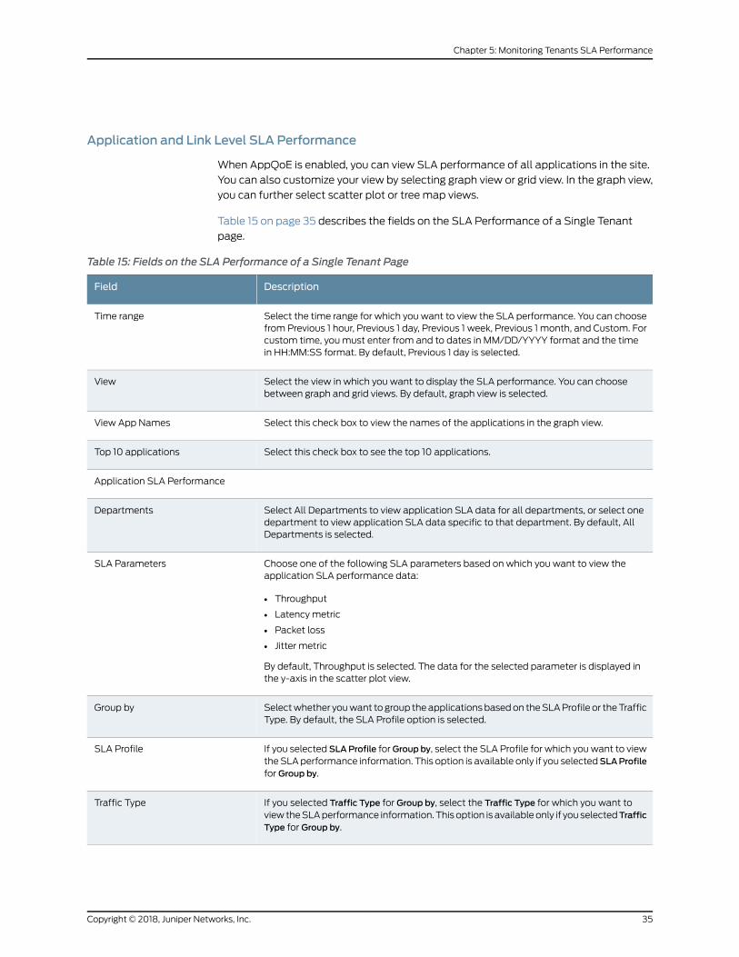
Application and Link Level SLA Performance
When AppQoE is enabled, you can view SLA performance of all applications in the site.
You can also customize your view by selecting graph view or grid view. In the graph view,
you can further select scatter plot or tree map views.
Table 15 on page 35 describes the fields on the SLA Performance of a Single Tenant
page.
Table 15: Fields on the SLA Performance of a Single Tenant Page
DescriptionField
Select the time range for which you want to view the SLA performance. You can choosefrom Previous 1 hour, Previous 1 day, Previous 1 week, Previous 1 month, and Custom. Forcustom time, youmust enter from and to dates in MM/DD/YYYY format and the timein HH:MM:SS format. By default, Previous 1 day is selected.
Time range
Select the view in which you want to display the SLA performance. You can choosebetween graph and grid views. By default, graph view is selected.
View
Select this check box to view the names of the applications in the graph view.View App Names
Select this check box to see the top 10 applications.Top 10 applications
Application SLA Performance
Select All Departments to view application SLA data for all departments, or select onedepartment to view application SLA data specific to that department. By default, AllDepartments is selected.
Departments
Choose one of the following SLA parameters based on which you want to view theapplication SLA performance data:
• Throughput
• Latency metric
• Packet loss
• Jitter metric
By default, Throughput is selected. The data for the selected parameter is displayed inthe y-axis in the scatter plot view.
SLA Parameters
Selectwhether youwant to group theapplicationsbasedon theSLAProfile or theTrafficType. By default, the SLA Profile option is selected.
Group by
If you selected SLAProfile forGroup by, select the SLA Profile for which youwant to viewtheSLAperformance information. This option is available only if you selectedSLAProfilefor Group by.
SLA Profile
If you selected Traffic Type for Group by, select the Traffic Type for which you want toview theSLAperformance information. Thisoption is availableonly if youselectedTrafficType for Group by.
Traffic Type
35Copyright © 2018, Juniper Networks, Inc.
Chapter 5: Monitoring Tenants SLA Performance
Table 15: Fields on the SLA Performance of a Single Tenant Page (continued)
DescriptionField
Select whether you want to view the SLA performance information for applications inthe Scatter Plot view or in Tree Graph view. By default, Scatter Plot is selected.
Graph
Link SLA Performance
Select the traffic type for which you want to view the link SLA performance. You canchoose either All Traffic Type or one of the available traffic types.
Traffic Type
Select the links for which you want to view the SLA performance. You can choose eitherAll Links or one of the available links.
Links
RelatedDocumentation
About the SLA Performance of All Tenants Page on page 30•
• Viewing the SLA Performance of a Site on page 37
• Viewing the SLA Performance of an Application or Application Group on page 41
• Creating SLA Profiles on page 169
Monitoring Application-Level SLA Performance for real time-optimized SD-WAN
CSOuses the system log information fromSRXdevices tomonitor application-level SLA
performance and displays the relevant information on theMonitor > Tenant SLA
Performance page of the Admin Portal and theMonitor > Application SLA Performance
page of the Customer Portal.
I
In real time-optimizedmode, CSOuses the class-of-service values and the probe results
to assign each application, site, and tenant scores that indicate the SLA performance.
For more information about the SLA performance scores, see “Understanding SLA
Performance Score for Applications, Links, Sites, and Tenants” on page 42.
The following sections explain how you can view the SLA performance information at
tenant level, site level, and application level:
1. Viewing SLA Performance of Tenants on page 36
2. Viewing SLA Performance of Sites on page 37
Viewing SLA Performance of Tenants
Service provider administrators can view the SLA performance of all the tenants from
theMonitor > Tenant SLA Performance page.
To view the SLA performance of all tenants:
1. From the administration portal, clickMonitor > Tenant SLA Performance.
Copyright © 2018, Juniper Networks, Inc.36
Contrail Service Orchestration User Guide
The “Tenant SLA Performance” on page 30 page appears.
2. Customize the view to your specific requirements.
For customization options, see Table 11 on page 31
The Tenants SLA Performance page displays the SLA performance information for
all the tenants in the format and for the time range you specified. For each of the
tenant, you can view the details as described in Table 12 on page 31
Viewing SLA Performance of Sites
Service provider administrators can view SLA performance information for all the sites
associated with a tenant.
To view SLA performance information for the sites associated with a tenant:
1. From the administration portal, clickMonitor > Tenant SLA Performance, and then
click the name of the tenant for which you want view the site-level SLA performance
information.
The Tenant Name SLA Performance page appears. For more information, see “About
the SLA Performance of a Single Tenant Page” on page 32.
2. Customize theviewas required. Formore informationabout thecustomizationoptions,
see Table 13 on page 33
The Tenant Name SLA Performance page displays the information in the format and
for the time range you specified. For each of the sites, you can view the information
as explained in Table 14 on page 34.
3. Click the name of the site to viewmore details about application-level and link-level
SLA performance. A new page appears with graphical representation of SLA
performance information for the site as well as the applications and links available
in the site.
You can customize the view as described in Table 15 on page 35.
Viewing the SLA Performance of a Site
You can use theMonitor > Tenant-Name SLA Performance > Site-Name SLA Performance
page in the Administration Portal to view SLA performance for all applications and
application groups in a site. You can view the SLA performance for all applications and
application groups in a site for a specified time range and in graph or grid views.
The Site-Name SLA Performance page is divided into the following three sections:
• SLA Not Met by SLA Profiles on page 38
• Applications SLA Performance by Throughput on page 38
• SLA Performance for ALL on page 40
37Copyright © 2018, Juniper Networks, Inc.
Chapter 5: Monitoring Tenants SLA Performance
SLANotMet by SLA Profiles
You can use the SLANotMet by SLA Profiles section on the Site_name SLA Performance
page to view the SLA profiles for which SLA requirements were not met and the time at
which theywerenotmet. They-axis represents theSLAprofilesand thex-axis represents
the specified time range. The SLANotMet by SLA Profiles section can be viewed and
remains the same in both graph and grid views.
To view a graphical representation of SLA profiles for which SLA target values were not
met:
1. Select the time range forwhich youwant to view theSLAprofiles forwhichSLA target
values were not met. You can choose from Previous 1 hour, Previous 1 day, Previous 1
week, Previous 1 month, and Custom. For custom time, youmust enter from and to
dates inMM/DD/YYYY format and the time inHH:MM:SS format. By default, Previous
1 day is selected.
The graphical representation of SLA profiles for which SLA target values were not
met is displayed for the selected time range.
2. (Optional) You can use the sliders at the sides of the graph to further customize the
time range.
The graphical representation of SLA profiles for which SLA target values were not
met is refreshed and displayed for the customized time range. The graphical
representation of SLA performance data in the subsequent sections on the page is
also refreshed and displayed for the customized time range.
Applications SLA Performance by Throughput
Youcan viewaverage throughput performanceof all applications andapplication groups
in a site. You can also customize your view by selecting graph view or grid view. In the
graph view, you can further select scatter plot or tree map views.
Toviewagraphical representationofaverage throughputperformanceofall applications
and application groups in a site:
1. Select Graph View at the top right of the page. By default, Graph View is selected.
Agraphical representationof average throughput performanceof all applications and
application groups in a site against the target throughput is displayed in the Scatter
Plot view. The y-axis represents the average throughput. 0%on the x-axis represents
the target throughput (in%) defined in the SLA profiles, while the regions on the left
and right of the target represent percentages below and above the target throughput,
respectively.
A carousel at the bottom of the section also displays the list of all applications and
application groupswith their SLA profiles, target throughput, and average throughput
values.
2. Click Legend at the bottom right of the section to view the plotting legend.
Copyright © 2018, Juniper Networks, Inc.38
Contrail Service Orchestration User Guide
The items described in the Legend are:
• A single application is represented by a blue circle.
• An application group is represented by a blue square.
• Anapplicationor applicationgroupwhose target throughput value in theSLAprofile
wasmodified during runtime is represented by an uncolored circle or uncolored
square, respectively.
• The SLA profiles are represented by their priority numbers within the colored or
uncolored circles and squares.
3. (Optional) You can use the sliders at the sides of the graph further to customize the
time range.
The carousel is refreshed for the customized time range.
4. Click the circles or squares to viewmore information about the application or
applicationgroups.See “Viewing theSLAPerformanceofanApplicationorApplication
Group” on page 41.
NOTE: You can also select TreeMap at the top right of the section to view a
list of all applications and application groups in a site and their averagethroughput values.
A list of all applications and application groups in a site along with theirassociated SLA profiles and the average throughput values is displayed.
To view a tabular representation of average throughput performance of all applications
and application groups in a site:
1. Select Grid View at the top right of the page.
A list of all applications and application groups along with their SLA profiles, average
throughput, and target throughput values is displayed in a tabular format.
Table 16 on page 39 describes the fields on the Applications SLA Performance by
Throughput grid view.
Table 16: Fields on the Applications SLA Performance by Throughput Grid View
DescriptionField
View name of the application or application group.Name
View the SLA profile associated with the application or application group.SLA Profile
View the type—application or application groupType
View the category of the application or application group. The value of category can beMessaging, Web, Infrastructure, Remote-Access, Multimedia, Video, and so on.
Category
39Copyright © 2018, Juniper Networks, Inc.
Chapter 5: Monitoring Tenants SLA Performance
Table 16: Fields on the Applications SLA Performance by Throughput Grid View (continued)
DescriptionField
View the number of sessions consumed by the application or application group.Sessions
View the average throughput performance value (in%) of the application or applicationgroup. Theupward triangle on the left of theaverage throughput performance value indicatesthat the average throughput is higher than the target throughput configured in theSLAprofileof the application or application group. The value (in%) denotes the percentage above thetarget throughput value.Similarly, thedownward triangleon the left of theaverage throughputperformance value indicates that the average throughput is lower than the target throughputconfigured in theSLAprofile of theapplicationor applicationgroup. The value (in%)denotesthe percentage below the target throughput value.
Throughput Avg. Performance
2. (Optional) Click the details icon to the left of the application or application group
name to viewmore details about the application or application group. See “Viewing
the SLA Performance of an Application or Application Group” on page 41.
SLA Performance for ALL
View a graphical representation of the performance of the SLA parameters such as
round-trip time (RTT), latency, packet loss, and jitter for the specified time range for
MPLS and InternetWAN links for all SLA profiles. The y-axis represents the SLA
parameters and the x-axis represents the specified time range. You can also view the
respective target SLA parameters in the graphs.
NOTE: Thegraphical representationof theperformanceofallSLAparametersfor theWAN links is available only in the graph view.
To view a graphical representation of the performance of all SLA parameters for the
WAN links:
• Select All at the top right of the section. By default, All is selected.
A graphical representation of the performance of the SLA parameters such as RTT,
latency, packet loss, and jitter for the specified time range for allWAN links is displayed.
• Selectwan_0,wan_1, and so on at the top right of the section to view the performance
of the SLA parameters for the MPLS and InternetWAN links. You can enable and
configurewan_0,wan_1, and so on andmap them toMPLS or Internet links when you
create a site.
The graphical representation of the performance of the SLA parameters such as RTT,
latency, packet loss, and jitter for the specified time range is refreshed and only the
performance for the selectedWAN link is displayed.
Copyright © 2018, Juniper Networks, Inc.40
Contrail Service Orchestration User Guide
• (Optional) Click Legend at the bottom right of the section to view the plotting legend
for thehorizontal dotted linesparallel to the x-axis in thegraphs. Thehorizontal dotted
lines represent the respective target SLA parameters of the SLA profiles.
NOTE: RTT is represented as Delay on the “Application SLA Profiles” onpage 168 page.
RelatedDocumentation
About the SLA Performance of All Tenants Page on page 30•
• About the SLA Performance of a Single Tenant Page on page 32
• Viewing the SLA Performance of an Application or Application Group on page 41
Viewing the SLA Performance of an Application or Application Group
You can use theMonitor > Tenant-Name SLA Performance > Site-Name SLA Performance
page in the Administration Portal to view the SLA performance of individual applications
andapplicationgroups inasite. YoucanalsoviewtheSLAperformanceof theassociated
SLA profile for all SLA parameters.
To view SLA performance of an application or application groups:
• Click one of the circles or squares in the Applications SLAPerformance by Throughput
section on the Site-Name SLA Performance page.
The page that appears displays SLA performance details of the application or
application group.
Table 17 on page 41 describes the fields on the application or application group SLA
Performance details page.
Table 17: Fields on the Application or Application Group Details Page
DescriptionField
View the category of the application or application group. The category can be Messaging,Web, Infrastructure, Remote-Access, Multimedia, Video, and so on.
You can also view a description of the application or application group.
Category and Description
View the name of the SLA profile associated with the application or application group.SLA
View the current target throughput defined in the SLA profile associated with the applicationor application group. If the target throughput wasmodified during runtime, the date and timewhen the throughput wasmodified and the previously defined throughput value are alsodisplayed.
Target
View the average throughout performance (in%) above or below the configured targetthroughput. The average throughput (in Mbps) is displayed within parentheses.
Avg. Performance
41Copyright © 2018, Juniper Networks, Inc.
Chapter 5: Monitoring Tenants SLA Performance
Table 17: Fields on the Application or Application Group Details Page (continued)
DescriptionField
View a graphical representation of the SLAmetrics by throughput during the specified timerange for thatapplicationorapplicationgroup.They-axis represents the throughput (inMbps).The x-axis represents the specified time range. Hover over the graph to view the throughputvalue and time at any specified point. You can also view the sessions consumed by theWANlinks for the application or application group for the specified time range.
SLA Metrics by Throughput
View the performance for all the SLA parameters of the SLA profile associated with theapplication or application group. The SLA performance is represented by a color-coded donutchart. The section in blue in the donut chart indicates the percentage of time duringwhich SLArequirements for the SLA profile were met. The section in red in the donut chart indicates thepercentage of time during which SLA requirements for the SLA profile were not met.
Click the red colored section of the donut chart to viewmore information about when SLArequirements for the SLA profile were not met. The SLA Profile Performance page appears.The SLA Profile Performance page displays the following fields:
• SLA Profile—SLA profile associated with the application or application group
• Target—Target throughput configured in the SLA profile
• SLAs Not Met—Percentage of time SLA requirements were not met for the SLA profile
• Sessions—Number of sessions consumed by the application or application group
• Start Time—Time at which theWAN links associated with the application or applicationgroups started to fail meeting the SLA requirements
• End Time—Time at which SLA profile requirements started to bemet again
• Avg Val—Average throughput (in Mbps) when the SLA requirements started to fail
• Duration—Total duration (in seconds) during which SLA requirements were not met
• From—SourceWAN link
• To—DestinationWAN link
Global SLA ProfilePerformance
RelatedDocumentation
About the SLA Performance of All Tenants Page on page 30•
• About the SLA Performance of a Single Tenant Page on page 32
• Viewing the SLA Performance of a Site on page 37
Understanding SLA Performance Score for Applications, Links, Sites, and Tenants
This topic explains the following SLA performance scores:
• Application Score on page 42
• Site Score on page 43
• Tenant Score on page 43
• Link Score on page 43
Application Score
FromRelease 3.3 onward, CSO supports Application Quality of Experience (AppQoE) to
improve the user experience at the application level. In real time-optimized SD-WAN
networks, CSOmonitors application traffic using passive probes, which are inline probes
Copyright © 2018, Juniper Networks, Inc.42
Contrail Service Orchestration User Guide
sent along with the application traffic. Based on various parameters collected from the
passive probes, CSO assigns a score to each of the applications. Based on the sampling
rate you specified as part of the traffic type profile, CSO sends passive probes to detect
packet loss, jitter, and violations in RTT. If the probe detects any of these issues, a syslog
is generated and a violation count is added for the session.
The following metrics are used to calculate the application score:
• Session Violation Count
• Sampling Percentage
• Total Session Count
NOTE: Application score is available only in real time-optimized SD-WANnetworks.
Site Score
For AppQoE enabled (real time-optimized SD-WAN) networks, site score is calculated
asanaggregateof individual parametersacrossall applications in the site. For information
about application score calculation, see “Application Score” on page 42.
The site score for bandwidth-optimized networks is calculated as an average of “Link
Score” on page 43.
Tenant Score
Tenant score is calculated as the average value of site scores. For information about site
score calculation, see “Site Score” on page 43.
Link Score
Link score is calculated based on the following SLA parameters collected using AppQoE
activeprobes (in real time-optimizednetworks)orRPMprobes (inbandwidth-optimized
networks):
• Latency
• Jitter
• Packet Loss
For VoIP traffic, the link score calculation also considers the R-Value and MOS.
43Copyright © 2018, Juniper Networks, Inc.
Chapter 5: Monitoring Tenants SLA Performance

Copyright © 2018, Juniper Networks, Inc.44
Contrail Service Orchestration User Guide
CHAPTER 6
Monitoring Jobs
• About the Jobs Page on page 45
• Viewing Job Details on page 47
• Editing and Deleting Scheduled Jobs on page 47
• Retrying a Failed Job on Devices on page 48
About the Jobs Page
To access this page, clickMonitor > Jobs.
Use this page to view the list of all jobs and the jobs that are scheduled to be executed.
You can view general information about the jobs and the overall progress and status of
the jobs. You can also edit and delete scheduled jobs.
Tasks You Can Perform
You can perform the following tasks from this page:
• View details about a job. See “Viewing Job Details” on page 47.
• Retry a job. See “Retrying a Failed Job on Devices” on page 48.
• Edit and delete schedule jobs. See “Editing and Deleting Scheduled Jobs” on page 47.
Field Descriptions
Table 18 on page 45 provides guidelines on using the fields on the Jobs page.
Table 18: Fields on the Jobs Page
DescriptionField
View the name of the job.
Example: MSEC_DOWNLOAD_IPS/APPLICATION_SIGNATURES_08_Jul_17_124229_024
Job Name
View the resource name of the job.
Example: Download IPS/Application Signatures
Resource Name
45Copyright © 2018, Juniper Networks, Inc.
Table 18: Fields on the Jobs Page (continued)
DescriptionField
View the status of the job to knowwhether the job succeeded or failed.
Example: Success
Status
View the name of the owner who created the job.
Example: cspadmin
Owner
View the number of tasks associated with the job.
Example: 2
For example, the tasks site.ucpe-32 and customer.sdwan are associated with this job.
Number of Tasks
View the job type.
Example: tssm import pop
Job Type
View the start date and time of a task associated with the job.Start Date
View the end date and time of a task associated with the job.End State
Field Descriptions
Table 19 on page 46 provides guidelines on using the fields on the Scheduled Jobs page.
Table 19: Fields on the Scheduled Jobs Page
DescriptionField
View the unique ID of the scheduled job. The value is generated by the database when a newschedule record is inserted into the database.
Example: 48
Schedule ID
View the unique name of the scheduled job.
Example: Tenant Delete_csp.tssm_remove_site_e340354716ae43859fad5ba15669eee2
Name
View the status of the last triggered job. The following state are available: scheduled, In progress,complete, or failed.
The default status is scheduled.
Status
View the job type.
Example: tssm onboard tenant
Job Type
View the name of the owner who scheduled the job.
Example: cspadmin
Owner
Copyright © 2018, Juniper Networks, Inc.46
Contrail Service Orchestration User Guide
Table 19: Fields on the Scheduled Jobs Page (continued)
DescriptionField
View the time when the job is scheduled to run next.Next Run Time
RelatedDocumentation
Editing and Deleting Scheduled Jobs on page 47•
• Retrying a Failed Job on Devices on page 48
Viewing Job Details
You can use the Detailed View page to view all the parameters of a job.
To view details of a job:
• Right-click the job name that you want to see the detailed view for and select Detail
View, or select the job and click More > Detail View.
• Alternatively, hover over the job name and click the Detailed View icon that appears
before it.
The Detailed View page appears, showing the details of the job and the number of tasks
associated with the job. See the relevant topic “About the Jobs Page” on page 303 for a
description of the fields on these pages.
RelatedDocumentation
About the Jobs Page on page 45•
Editing and Deleting Scheduled Jobs
You can edit and delete scheduled jobs. This topic contains the following sections:
• Editing Scheduled Jobs on page 47
• Deleting Scheduled Jobs on page 48
Editing Scheduled Jobs
You canmodify the date and time of deployment of scheduled jobs.
Tomodify a scheduled job:
1. SelectMonitor > Jobs > Scheduled Jobs.
The Scheduled Jobs page appears.
2. Select the job that you want to reschedule the deployment, and click the edit icon.
The Edit Schedule page appears.
47Copyright © 2018, Juniper Networks, Inc.
Chapter 6: Monitoring Jobs
3. To execute the job immediately, delete the existing scheduled entry, create a new
entry, and then select the Run now option. To reschedule the job for a later date and
time, or select the Schedule at a later time option.
4. Click Save to save the changes.
Themodified job and its details are displayed on a page
Deleting Scheduled Jobs
You can delete one or more scheduled jobs.
To delete a scheduled job:
1. SelectMonitor > Jobs> Scheduled Jobs.
The Scheduled Jobs page appears with a list of jobs.
2. Select the check box of the job that you want to delete and then click the delete icon
(X).
The Confirm Delete page appears.
3. Click Yes to confirm.
The scheduled job is deleted.
RelatedDocumentation
About the Jobs Page on page 45•
• Viewing Job Details on page 47
Retrying a Failed Job on Devices
You can retry tssm.ztp type jobs that did not complete successfully on your devices.
Retrying a failed job saves time because instead of creating the job again and executing
it, you can simply retry the failed job.
NOTE: The Retry Job button is enabled only for failed ZTP jobs and it is
available only for All Tenants scope.
To retry a job that was not successful:
1. SelectMonitor > Jobs.
The Jobs page appears.
2. Select the failed job (tssm.ztp type) that you want to retry.
Copyright © 2018, Juniper Networks, Inc.48
Contrail Service Orchestration User Guide
3. At the top right corner of the Jobs page, click the Retry Job button.
The job is executed in the back endand the device status on theSites page is changed
to PROVISIONED.
RelatedDocumentation
• About the Jobs Page on page 45
• Editing and Deleting Scheduled Jobs on page 47
49Copyright © 2018, Juniper Networks, Inc.
Chapter 6: Monitoring Jobs

Copyright © 2018, Juniper Networks, Inc.50
Contrail Service Orchestration User Guide
CHAPTER 7
Managing POPs
• About the POPs Page on page 51
• Creating a Single POP on page 53
• Importing Data for Multiple POPs on page 64
• Viewing the History of POP Data Imports on page 69
• Viewing the History of POP Data Deletions on page 71
• Managing a Single POP on page 72
• About the VIMs Page on page 73
• Creating a Cloud VIM on page 75
• About the EMS Page on page 79
• Creating an EMS on page 80
• Changing the Junos Space Virtual Appliance Password on page 81
• About the Routers Page on page 82
• Creating Devices on page 83
• Configuring Devices on page 85
• View the History of Device Data Deletions on page 88
About the POPs Page
To access this page, click Resources > POPs.
You can use the POPs page to view the list of available POPs in the service provider
network. You can also view information about each POP in the network
Tasks You Can Perform
You can perform the following tasks from this page:
• Quickly view important data about POPs in the widgets that appear at the top of the
page. See Table 20 on page 52.
• Create a POP. See “Creating a Single POP” on page 53.
• Import data for multiple POPs. See “Importing Data for Multiple POPs” on page 64.
51Copyright © 2018, Juniper Networks, Inc.
• View the history of POP data imports. See “Viewing the History of POP Data Imports”
on page 69.
• ViewthehistoryofPOPdatadeletions.See “Viewing theHistoryofPOPDataDeletions”
on page 71.
• View details about a POP. Hover over the name of a POP or clickMore > Quick View.
See “Viewing Object Details” on page 14.
• Show or hide columns about the POPs. See “Sorting Objects” on page 15.
• Search an object about the POPs. See “Searching for Text in an Object Data Table”
on page 15.
• Delete a POP. See “Deleting Objects” on page 14.
Field Descriptions
Table 20 on page 52 describes the widgets on the POPs page.
Table 20:Widgets on the POPs Page
DescriptionWidget
View the top three POPs using the largest percentage of CPU from theassigned cores.
Click a POP name to view detailed information about the resources thePOP uses.
Top POPs by CPU Allocation
View the top threePOPsusing themost storage fromtheallocatedstoragespace in gigabytes (GB).
Click a POP name to view detailed information about the resources thePOP uses.
Top POPs by Storage Allocation
View the top three POPs using the most memory from the allocatedmemory size in megabytes (MB).
Click a POP name to view detailed information about the resources thePOP uses.
Top POPs by Memory Allocation
Table 21 on page 52 shows the fields on the POPs page.
Table 21: Fields on the POPs Page
DescriptionField
View the name of the POP.
Example: regional
Name
View the location of the POP.
Example: Sunnyvale, CA
Location
View the amount of CPU allocated for the POP.CPU Allocated
Copyright © 2018, Juniper Networks, Inc.52
Contrail Service Orchestration User Guide
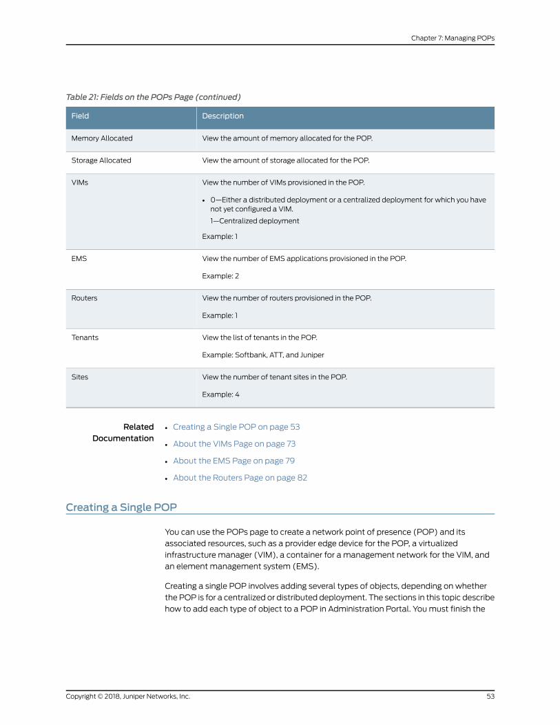
Table 21: Fields on the POPs Page (continued)
DescriptionField
View the amount of memory allocated for the POP.Memory Allocated
View the amount of storage allocated for the POP.Storage Allocated
View the number of VIMs provisioned in the POP.
• 0—Either a distributed deployment or a centralized deployment for which you havenot yet configured a VIM.
1—Centralized deployment
Example: 1
VIMs
View the number of EMS applications provisioned in the POP.
Example: 2
EMS
View the number of routers provisioned in the POP.
Example: 1
Routers
View the list of tenants in the POP.
Example: Softbank, ATT, and Juniper
Tenants
View the number of tenant sites in the POP.
Example: 4
Sites
RelatedDocumentation
Creating a Single POP on page 53•
• About the VIMs Page on page 73
• About the EMS Page on page 79
• About the Routers Page on page 82
Creating a Single POP
You can use the POPs page to create a network point of presence (POP) and its
associated resources, such as a provider edge device for the POP, a virtualized
infrastructure manager (VIM), a container for a management network for the VIM, and
an element management system (EMS).
Creating a single POP involves adding several types of objects, depending on whether
the POP is for a centralized or distributed deployment. The sections in this topic describe
how to add each type of object to a POP in Administration Portal. Youmust finish the
53Copyright © 2018, Juniper Networks, Inc.
Chapter 7: Managing POPs
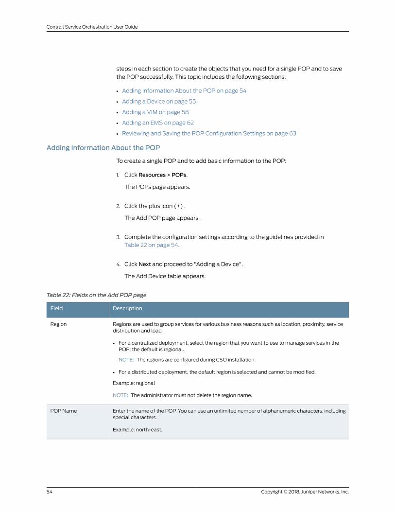
steps in each section to create the objects that you need for a single POP and to save
the POP successfully. This topic includes the following sections:
• Adding Information About the POP on page 54
• Adding a Device on page 55
• Adding a VIM on page 58
• Adding an EMS on page 62
• Reviewing and Saving the POP Configuration Settings on page 63
Adding Information About the POP
To create a single POP and to add basic information to the POP:
1. Click Resources > POPs.
The POPs page appears.
2. Click the plus icon (+) .
The Add POP page appears.
3. Complete the configuration settings according to the guidelines provided in
Table 22 on page 54.
4. Click Next and proceed to "Adding a Device".
The Add Device table appears.
Table 22: Fields on the Add POP page
DescriptionField
Regions are used to group services for various business reasons such as location, proximity, servicedistribution and load.
• For a centralized deployment, select the region that you want to use to manage services in thePOP; the default is regional.
NOTE: The regions are configured during CSO installation.
• For a distributed deployment, the default region is selected and cannot bemodified.
Example: regional
NOTE: The administrator must not delete the region name.
Region
Enter the name of the POP. You can use an unlimited number of alphanumeric characters, includingspecial characters.
Example: north-east.
POP Name
Copyright © 2018, Juniper Networks, Inc.54
Contrail Service Orchestration User Guide
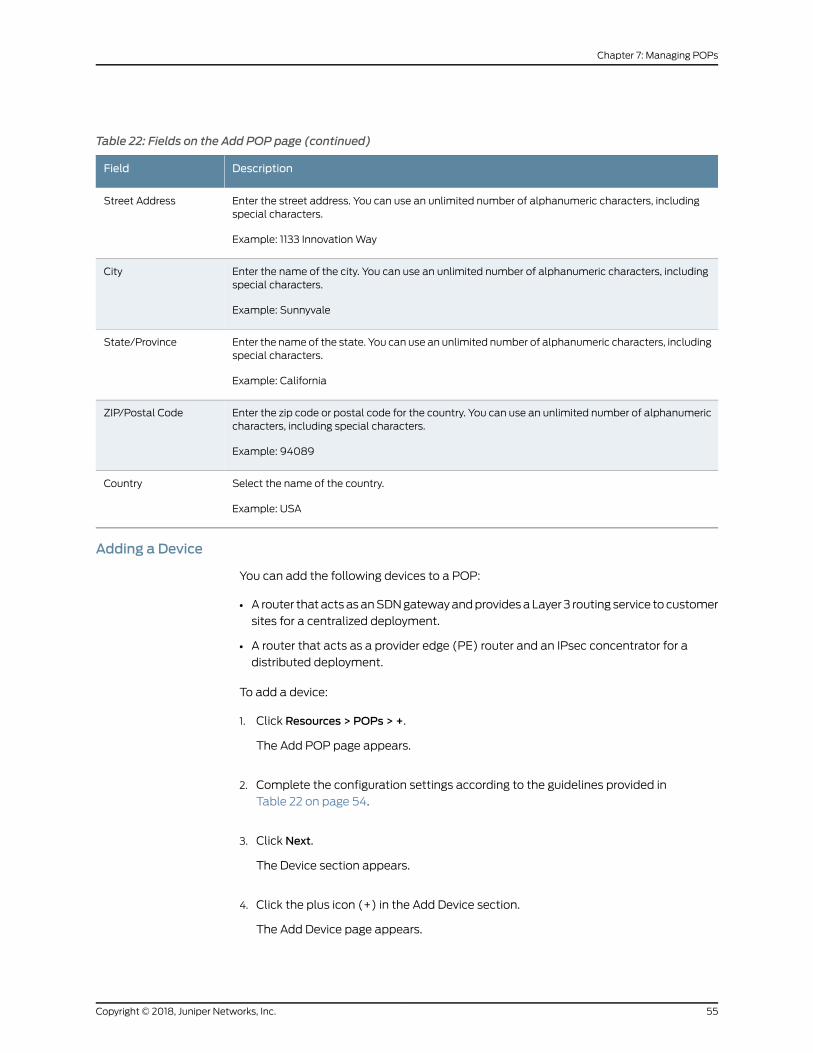
Table 22: Fields on the Add POP page (continued)
DescriptionField
Enter the street address. You can use an unlimited number of alphanumeric characters, includingspecial characters.
Example: 1133 InnovationWay
Street Address
Enter the name of the city. You can use an unlimited number of alphanumeric characters, includingspecial characters.
Example: Sunnyvale
City
Enter the name of the state. You can use an unlimited number of alphanumeric characters, includingspecial characters.
Example: California
State/Province
Enter the zip code or postal code for the country. You can use an unlimited number of alphanumericcharacters, including special characters.
Example: 94089
ZIP/Postal Code
Select the name of the country.
Example: USA
Country
Adding a Device
You can add the following devices to a POP:
• A router thatactsasanSDNgatewayandprovidesaLayer 3 routing service tocustomer
sites for a centralized deployment.
• A router that acts as a provider edge (PE) router and an IPsec concentrator for a
distributed deployment.
To add a device:
1. Click Resources > POPs > +.
The Add POP page appears.
2. Complete the configuration settings according to the guidelines provided in
Table 22 on page 54.
3. Click Next.
The Device section appears.
4. Click the plus icon (+) in the Add Device section.
The Add Device page appears.
55Copyright © 2018, Juniper Networks, Inc.
Chapter 7: Managing POPs
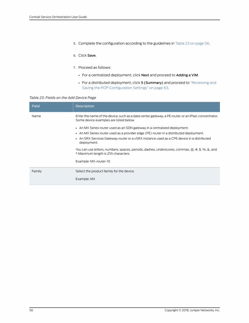
5. Complete the configuration according to the guidelines in Table 23 on page 56.
6. Click Save.
7. Proceed as follows:
• For a centralized deployment, click Next and proceed to Adding a VIM.
• For a distributed deployment, click 5 (Summary) and proceed to “Reviewing and
Saving the POP Configuration Settings” on page 63.
Table 23: Fields on the Add Device Page
DescriptionField
Enter the nameof the device, such as a data center gateway, a PE router, or an IPsec concentrator.Some device examples are listed below.
• AnMX Series router used as an SDN gateway in a centralized deployment.
• AnMX Series router used as a provider edge (PE) router in a distributed deployment.
• An SRX Services Gateway router or a vSRX instance used as a CPE device in a distributeddeployment.
You can use letters, numbers, spaces, periods, dashes, underscores, commas, @, #, $, %, &, and*. Maximum length is 255 characters.
Example: MX-router-10
Name
Select the product family for the device.
Example: MX
Family
Copyright © 2018, Juniper Networks, Inc.56
Contrail Service Orchestration User Guide
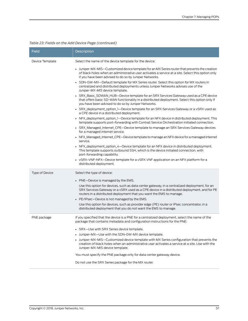
Table 23: Fields on the Add Device Page (continued)
DescriptionField
Select the name of the device template for the device:
• Juniper-MX-MIS—Customizeddevice template foranMXSeries router thatprevents thecreationof black holes when an administrative user activates a service at a site. Select this option onlyif you have been advised to do so by Juniper Networks.
• SDN-GW-MX—Default template for MX Series router. Select this option for MX routers incentralized and distributed deployments unless Juniper Networks advises use of theJuniper-MX-MIS device template.
• SRX_Basic_SDWAN_HUB—Device template for anSRXServicesGatewayusedas aCPEdevicethat offers basic SD-WAN functionality in a distributed deployment. Select this option only ifyou have been advised to do so by Juniper Networks.
• SRX_deployment_option_1—Device template for an SRX Services Gateway or a vSRX used asa CPE device in a distributed deployment.
• NFX_deployment_option_1—Device template for anNFXdevice in distributed deployment. Thistemplate supports port-forwarding with Contrail Service Orchestration initiated connection.
• SRX_Managed_Internet_CPE—Device template to manage an SRX Services Gateway devicesfor a managed internet service.
• NFX_Managed_Internet_CPE—Device template tomanageanNFXdevice foramanaged internetservice.
• NFX_deployment_option_4—Device template for an NFX device in distributed deployment.This template supports outbound SSH, which is the device initiated connection, withport-forwarding capability.
• vSRX-VNF-NFX—Device template for a vSRX VNF application on an NFX platform for adistributed deployment.
Device Template
Select the type of device:
• PNE—Device is managed by the EMS.
Use this option for devices, such as data center gateway, in a centralized deployment, for anSRX Services Gateway or a vSRX used as a CPE device in a distributed deployment, and for PErouters in a distributed deployment that you want the EMS tomanage.
• PE/IPsec—Device is not managed by the EMS.
Use this option for devices, such as provider edge (PE) router or IPsec concentrator, in adistributed deployment that you do not want the EMS tomanage.
Type of Device
If you specified that the device is a PNE for a centralized deployment, select the name of thepackage that contains metadata and configuration instructions for the PNE:
• SRX—Use with SRX Series device template.
• Juniper-MX—Use with the SDN-GW-MX device template.
• Juniper-MX-MIS—Customized device template with MX Series configuration that prevents thecreation of black holes when an administrative user activates a service at a site. Use with theJuniper-MX-MIS device template.
Youmust specify the PNE package only for data center gateway device.
Do not use the SRX Series package for the MX router.
PNE package
57Copyright © 2018, Juniper Networks, Inc.
Chapter 7: Managing POPs
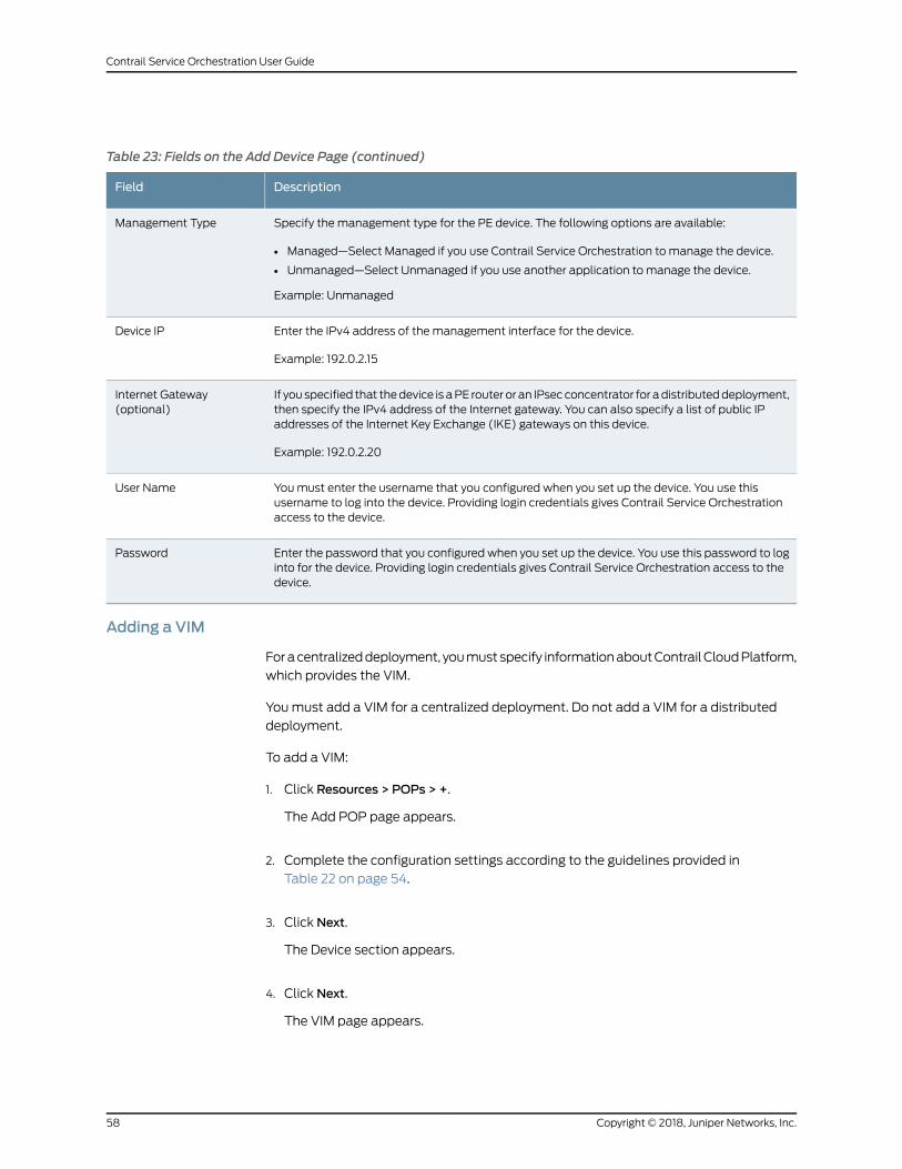
Table 23: Fields on the Add Device Page (continued)
DescriptionField
Specify the management type for the PE device. The following options are available:
• Managed—Select Managed if you use Contrail Service Orchestration to manage the device.
• Unmanaged—Select Unmanaged if you use another application to manage the device.
Example: Unmanaged
Management Type
Enter the IPv4 address of the management interface for the device.
Example: 192.0.2.15
Device IP
If you specified that thedevice is aPE router or an IPsecconcentrator for adistributeddeployment,then specify the IPv4 address of the Internet gateway. You can also specify a list of public IPaddresses of the Internet Key Exchange (IKE) gateways on this device.
Example: 192.0.2.20
Internet Gateway(optional)
Youmust enter the username that you configured when you set up the device. You use thisusername to log into the device. Providing login credentials gives Contrail Service Orchestrationaccess to the device.
User Name
Enter the password that you configured when you set up the device. You use this password to loginto for the device. Providing login credentials gives Contrail Service Orchestration access to thedevice.
Password
Adding a VIM
Foracentralizeddeployment, youmustspecify informationaboutContrailCloudPlatform,
which provides the VIM.
Youmust add a VIM for a centralized deployment. Do not add a VIM for a distributed
deployment.
To add a VIM:
1. Click Resources > POPs > +.
The Add POP page appears.
2. Complete the configuration settings according to the guidelines provided in
Table 22 on page 54.
3. Click Next.
The Device section appears.
4. Click Next.
The VIM page appears.
Copyright © 2018, Juniper Networks, Inc.58
Contrail Service Orchestration User Guide
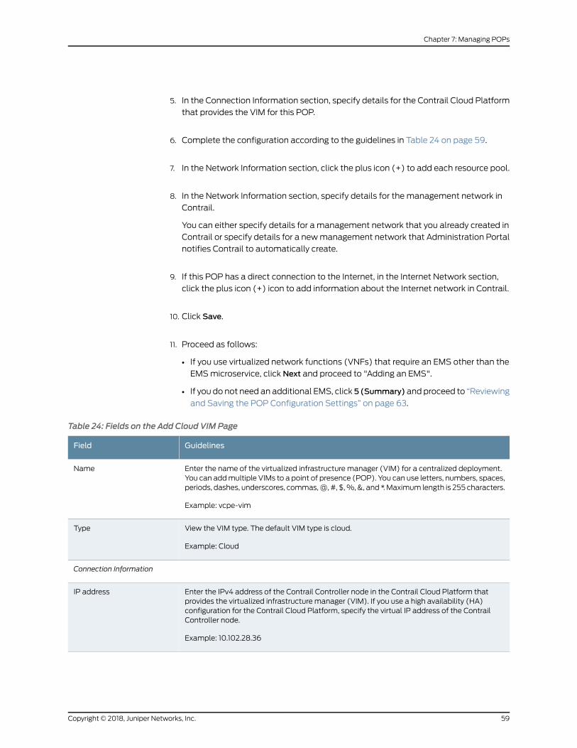
5. In the Connection Information section, specify details for the Contrail Cloud Platform
that provides the VIM for this POP.
6. Complete the configuration according to the guidelines in Table 24 on page 59.
7. In the Network Information section, click the plus icon (+) to add each resource pool.
8. In the Network Information section, specify details for the management network in
Contrail.
You can either specify details for a management network that you already created in
Contrail or specify details for a newmanagement network that Administration Portal
notifies Contrail to automatically create.
9. If this POP has a direct connection to the Internet, in the Internet Network section,
click the plus icon (+) icon to add information about the Internet network in Contrail.
10. Click Save.
11. Proceed as follows:
• If you use virtualized network functions (VNFs) that require an EMS other than the
EMSmicroservice, click Next and proceed to "Adding an EMS".
• If you do not need an additional EMS, click 5 (Summary) and proceed to “Reviewing
and Saving the POP Configuration Settings” on page 63.
Table 24: Fields on the Add Cloud VIM Page
GuidelinesField
Enter the name of the virtualized infrastructure manager (VIM) for a centralized deployment.You can addmultiple VIMs to a point of presence (POP). You can use letters, numbers, spaces,periods, dashes, underscores, commas,@, #, $,%,&, and *.Maximum length is 255 characters.
Example: vcpe-vim
Name
View the VIM type. The default VIM type is cloud.
Example: Cloud
Type
Connection Information
Enter the IPv4 address of the Contrail Controller node in the Contrail Cloud Platform thatprovides the virtualized infrastructure manager (VIM). If you use a high availability (HA)configuration for the Contrail Cloud Platform, specify the virtual IP address of the ContrailController node.
Example: 10.102.28.36
IP address
59Copyright © 2018, Juniper Networks, Inc.
Chapter 7: Managing POPs
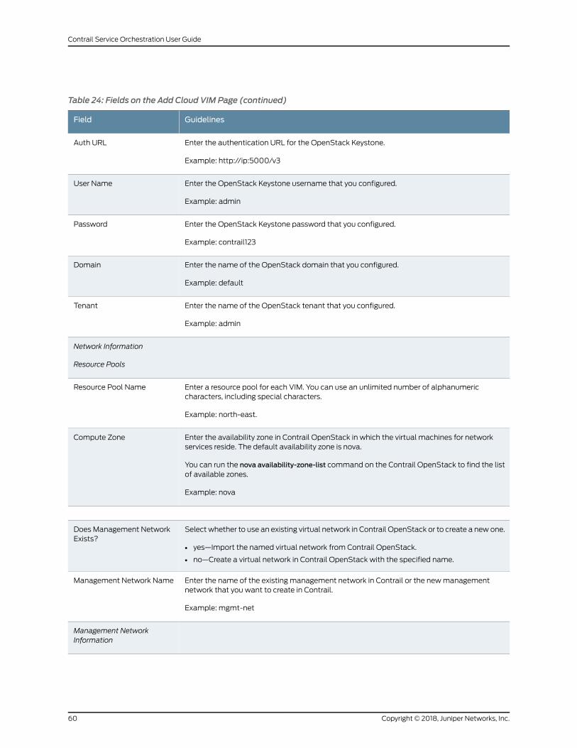
Table 24: Fields on the Add Cloud VIM Page (continued)
GuidelinesField
Enter the authentication URL for the OpenStack Keystone.
Example: http://ip:5000/v3
Auth URL
Enter the OpenStack Keystone username that you configured.
Example: admin
User Name
Enter the OpenStack Keystone password that you configured.
Example: contrail123
Password
Enter the name of the OpenStack domain that you configured.
Example: default
Domain
Enter the name of the OpenStack tenant that you configured.
Example: admin
Tenant
Network Information
Resource Pools
Enter a resource pool for each VIM. You can use an unlimited number of alphanumericcharacters, including special characters.
Example: north-east.
Resource Pool Name
Enter the availability zone in Contrail OpenStack in which the virtual machines for networkservices reside. The default availability zone is nova.
You can run the nova availability-zone-list command on the Contrail OpenStack to find the listof available zones.
Example: nova
Compute Zone
Select whether to use an existing virtual network in Contrail OpenStack or to create a new one.
• yes—Import the named virtual network from Contrail OpenStack.
• no—Create a virtual network in Contrail OpenStack with the specified name.
Does Management NetworkExists?
Enter the name of the existing management network in Contrail or the newmanagementnetwork that you want to create in Contrail.
Example: mgmt-net
Management Network Name
Management NetworkInformation
Copyright © 2018, Juniper Networks, Inc.60
Contrail Service Orchestration User Guide
Table 24: Fields on the Add Cloud VIM Page (continued)
GuidelinesField
Specify one or more route targets for the existing management network in Contrail or the newmanagement network that you want to create in Contrail.
Example: 64512:10000.
Route Target
Specify one or more prefixes that define the subnets for the Contrail Compute nodes. You canuse an IPv4 address. Specify one or more IPv4 prefixes for the existing network in Contrail orthe new network that you want to create in Contrail.
Example: 192.0.2.0/24.
Subnet
Internet Network Information
Enter the name of the Internet network.
Example: int-net
Network Name
Specify whether to use an existing virtual network in Contrail OpenStack or to create a newone.
• True—Import the named virtual network from Contrail OpenStack.
• False—Create a virtual network in Contrail OpenStack with the specified name.
Does Exist
Select the route target for the internet network in Contrail.
Example: 64512:10000.
Route Target
Select the prefix that defines the subnet for the Contrail Compute nodes.
You can use an IPv4 address.
Example: 192.0.2.0/24.
Subnet
Service Profile Information
Enter the name of the service profile in a VIM instance. Create one or more service profiles ifyou use a dedicated OpenStack Keystone for Contrail Service Orchestration in a centralizeddeployment. A service profile specifies the Contrail OpenStack tenant, domain, and logincredentials. After Contrail Service Orchestration authenticates a tenant (customer), it usesthe information in the service profile to provide access to Contrail OpenStack.
Example: vim-service-profile
Profile Name
Enter the name of the infra tenant for whom you want to assign the service profile.
Example: test-tenant
Tenant Name
Enter the Infra domain name.
Example: Default
Domain Name
61Copyright © 2018, Juniper Networks, Inc.
Chapter 7: Managing POPs
Table 24: Fields on the Add Cloud VIM Page (continued)
GuidelinesField
Enter the username of the tenant.
Example: admin
User Name
Enter the password for the tenant user.
Example: password123
Password
Select the name of the default service profile if you use a dedicated OpenStack Keystone forContrail Service Orchestration. If you do not specify a service profile when you configure thetenant, Contrail Service Orchestration uses the default profile to authenticate the tenant.
Example: default-service-profile
Default Service Profile
Adding an EMS
Configureanelementmanagementsystem(EMS) if youusevirtualizednetwork functions
(VNFs) that require an EMS other than the EMSmicroservice.
To add an EMS:
1. Click Resources > POPs > +.
The Add POP page appears.
2. Complete the configuration settings according to the guidelines provided in
Table 22 on page 54.
3. Click Next.
The Device section appears.
4. Click Next.
The VIM page appears.
5. Click Next.
The EMS page appears.
6. Click the plus icon (+) to add the EMS.
7. Complete the configuration according to the guidelines in Table 25 on page 63.
8. Click Save.
9. Click Next to review the configuration settings for the POP.
Copyright © 2018, Juniper Networks, Inc.62
Contrail Service Orchestration User Guide
Table 25: Fields on the Add EMS Page
GuidelinesField
Nameof theEMS.This field isauto-populatedwith thenamethat youspecifiedwhenyoudeployedthe Junos Space Virtual Appliance.
Example: Junos Space
Name
Enter the IPv4 address of the Junos SpaceWeb user interface (UI).
For a redundant Contrail Service Orchestration, configure the IP address of theWeb UI for theprimary Junos Space Virtual Appliance.
Example: 192.0.2.3.
IP
Enter the vendor name for the EMS.
Example: Juniper Networks
Vendor
Enter the version number of the EMS. The default version is 15.1.
Example: 15.1
Version
Enter the authentication URL for the EMS application.Authentication URL
Enter the username of the device administrator that you configured. This user should be assignedthe admin role in all the tenants. The default username is super.
Example: super
User Name
Enter the administrator password that you configured. The default password is juniper123.
Example: juniper123
Password
Reviewing and Saving the POP Configuration Settings
After you have configured a POP and its associated resources, you can review and save
a copy of the configuration settings. Finally, you must save the POP that you configured.
1. Click Resources > POPs > +.
The Add POP page appears.
2. Complete the configuration settings according to the guidelines provided in
Table 22 on page 54.
3. Click Next.
The Device section appears.
4. Click Next.
The VIM page appears.
63Copyright © 2018, Juniper Networks, Inc.
Chapter 7: Managing POPs
5. Click Next.
The EMS page appears.
6. Click Next.
The Summary page appears.
7. Click Summary > Edit to edit the configuration settings of the objects that you
configured.
8. Click Download POP Payload to save a JSON file of the configuration settings of the
objects that you configured.
9. ClickOK to save the POP configuration. If you want to discard your changes, click
Cancel instead.
RelatedDocumentation
About the POPs Page on page 51•
• About the EMS Page on page 79
• About the VIMs Page on page 73
• About the Routers Page on page 82
Importing Data for Multiple POPs
You can use the Import POPs page to import a POP and its associated resources, such
as a provider edge device for the POP, a virtualized infrastructure manager (VIM), a
container for management network for the VIM, and an element management system
(EMS).
• Customizing a POP Data File on page 64
• Uploading a POP Data File on page 68
Customizing a POPData File
To customize a POP data file:
1. Select Resources > POPs.
2. Click Import POPs > Import.
The Import POPs page appears.
3. Click the Download Sample JSON link to open and save the sample JSON data file.
The sample file opens at the bottom of the page.
Copyright © 2018, Juniper Networks, Inc.64
Contrail Service Orchestration User Guide
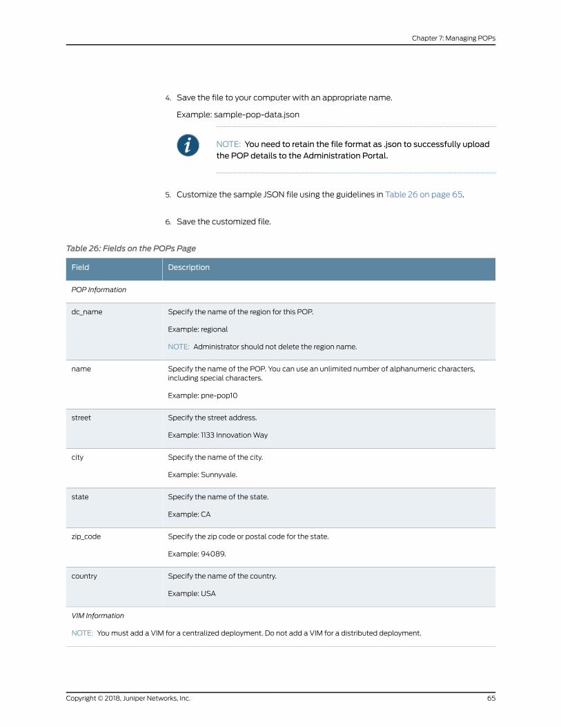
4. Save the file to your computer with an appropriate name.
Example: sample-pop-data.json
NOTE: You need to retain the file format as .json to successfully uploadthe POP details to the Administration Portal.
5. Customize the sample JSON file using the guidelines in Table 26 on page 65.
6. Save the customized file.
Table 26: Fields on the POPs Page
DescriptionField
POP Information
Specify the name of the region for this POP.
Example: regional
NOTE: Administrator should not delete the region name.
dc_name
Specify the name of the POP. You can use an unlimited number of alphanumeric characters,including special characters.
Example: pne-pop10
name
Specify the street address.
Example: 1133 InnovationWay
street
Specify the name of the city.
Example: Sunnyvale.
city
Specify the name of the state.
Example: CA
state
Specify the zip code or postal code for the state.
Example: 94089.
zip_code
Specify the name of the country.
Example: USA
country
VIM Information
NOTE: Youmust add a VIM for a centralized deployment. Do not add a VIM for a distributed deployment.
65Copyright © 2018, Juniper Networks, Inc.
Chapter 7: Managing POPs
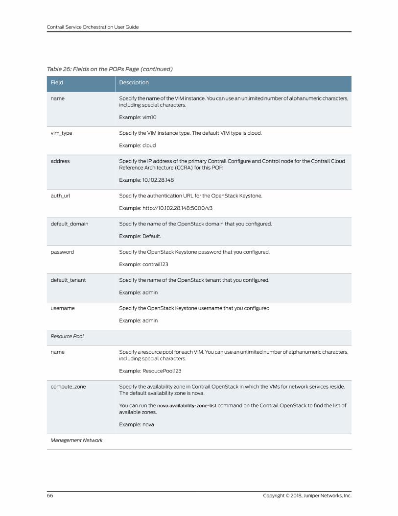
Table 26: Fields on the POPs Page (continued)
DescriptionField
Specify thenameof theVIM instance.Youcanuseanunlimitednumberofalphanumericcharacters,including special characters.
Example: vim10
name
Specify the VIM instance type. The default VIM type is cloud.
Example: cloud
vim_type
Specify the IP address of the primary Contrail Configure and Control node for the Contrail CloudReference Architecture (CCRA) for this POP.
Example: 10.102.28.148
address
Specify the authentication URL for the OpenStack Keystone.
Example: http://10.102.28.148:5000/v3
auth_url
Specify the name of the OpenStack domain that you configured.
Example: Default.
default_domain
Specify the OpenStack Keystone password that you configured.
Example: contrail123
password
Specify the name of the OpenStack tenant that you configured.
Example: admin
default_tenant
Specify the OpenStack Keystone username that you configured.
Example: admin
username
Resource Pool
Specify a resourcepool for eachVIM.Youcanuseanunlimitednumberof alphanumeric characters,including special characters.
Example: ResoucePool123
name
Specify the availability zone in Contrail OpenStack in which the VMs for network services reside.The default availability zone is nova.
You can run the nova availability-zone-list command on the Contrail OpenStack to find the list ofavailable zones.
Example: nova
compute_zone
Management Network
Copyright © 2018, Juniper Networks, Inc.66
Contrail Service Orchestration User Guide
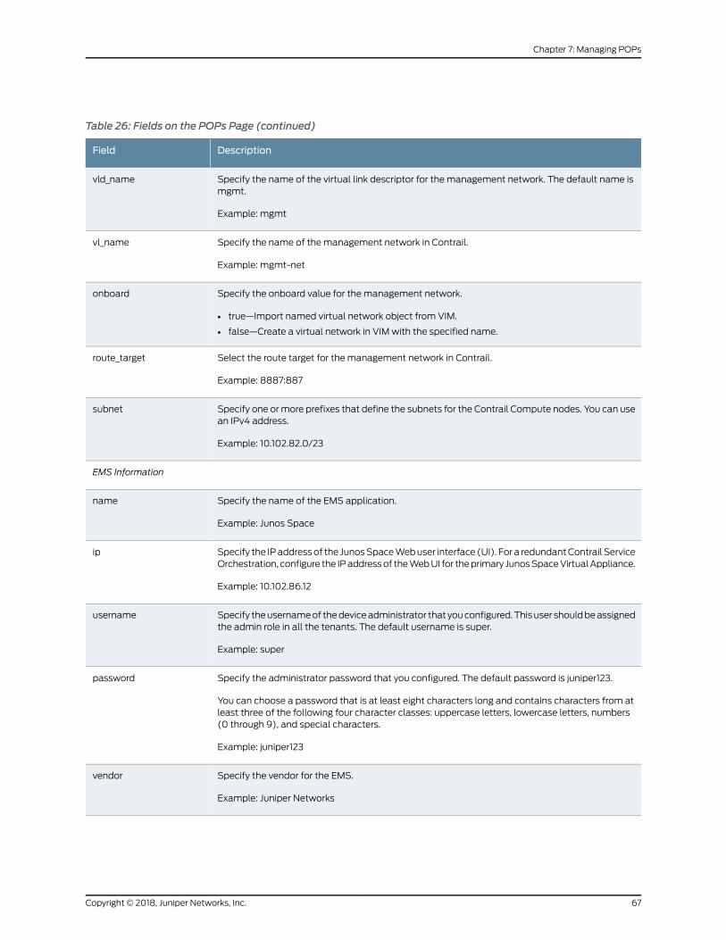
Table 26: Fields on the POPs Page (continued)
DescriptionField
Specify the name of the virtual link descriptor for the management network. The default name ismgmt.
Example: mgmt
vld_name
Specify the name of the management network in Contrail.
Example: mgmt-net
vl_name
Specify the onboard value for the management network.
• true—Import named virtual network object from VIM.
• false—Create a virtual network in VIM with the specified name.
onboard
Select the route target for the management network in Contrail.
Example: 8887:887
route_target
Specify one ormore prefixes that define the subnets for the Contrail Compute nodes. You can usean IPv4 address.
Example: 10.102.82.0/23
subnet
EMS Information
Specify the name of the EMS application.
Example: Junos Space
name
Specify the IPaddressof the JunosSpaceWebuser interface (UI). For a redundantContrail ServiceOrchestration, configure the IPaddressof theWebUI for theprimary JunosSpaceVirtualAppliance.
Example: 10.102.86.12
ip
Specify theusernameof thedeviceadministrator that youconfigured.Thisuser shouldbeassignedthe admin role in all the tenants. The default username is super.
Example: super
username
Specify the administrator password that you configured. The default password is juniper123.
You can choose a password that is at least eight characters long and contains characters from atleast three of the following four character classes: uppercase letters, lowercase letters, numbers(0 through 9), and special characters.
Example: juniper123
password
Specify the vendor for the EMS.
Example: Juniper Networks
vendor
67Copyright © 2018, Juniper Networks, Inc.
Chapter 7: Managing POPs
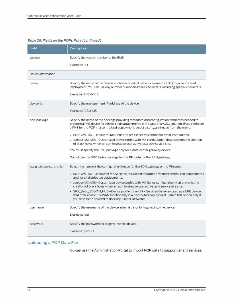
Table 26: Fields on the POPs Page (continued)
DescriptionField
Specify the version number of the EMS.
Example: 15.1
version
Device Information
Specify the name of the device, such as a physical network element (PNE) for a centralizeddeployment. You can use any number of alphanumeric characters, including special characters.
Example: PNE-MX10
name
Specify the management IP address of the device.
Example: 192.0.2.15.
device_ip
Specify the name of the package providing metadata and configuration templates needed toprogramaPNEdevice for service chainattachments in the caseof a vCSOsolution. If youconfigurea PNE for the POP in a centralized deployment, select a software image from themenu:
• SDN-GW-MX—Default for MX Series router. Select this option for most installations.
• Juniper-MX-MIS—Customized device profile with MX configuration that prevents the creationof black holes when an administrative user activates a service at a site.
Youmust specify the PNE package only for a data center gateway device.
Do not use the SRX Series package for the PE router or the SDN gateway.
pne_package
Select the name of the configuration image for the SDN gateway or the PE router.
• SDN-GW-MX—Default forMXSeries router. Select this option formost centralizeddeploymentsand for all distributed deployments.
• Juniper-MX-MIS—Customized device profile with MX Series configuration that prevents thecreation of black holes when an administrative user activates a service at a site.
• SRX_Basic_SDWAN_HUB—Device profile for an SRX Services Gateway used as a CPE devicethat offers basic SD-WAN functionality in a distributed deployment. Select this option only ifyou have been advised to do so by Juniper Networks.
assigned_device_profile
Specify the username of the device administrator for logging into the device.
Example: root
username
Specify the password for logging into the device.
Example: pwd123
password
Uploading a POPData File
You can use the Administration Portal to import POP data to support tenant services.
Copyright © 2018, Juniper Networks, Inc.68
Contrail Service Orchestration User Guide
To upload a POP data file:
1. Select Resources > POPs.
2. Click Import POPs > Import.
The Import POPs page appears.
3. Click Browse and navigate to the directory containing the POP data file.
4. Select the file and clickOpen.
5. Click Import. If you want to discard the import process, click Cancel instead.
A success message is displayed indicating that the job was uploaded successfully.
See Also Creating a Single POP on page 53•
• Viewing the History of POP Data Imports on page 69
• Viewing the History of POP Data Deletions on page 71
Viewing the History of POP Data Imports
You can use the Import History page to view the imported POP data. You can also view
the details of the imported logs and their status.
To import your POP data, see “Importing Data for Multiple POPs” on page 64.
To view the history of imported POP data:
1. Click Resources > POPs > Import POPs > Import History.
The Import History page is displayed. Table 27 on page 70 describes the fields on the
Import History page.
2. Click a task name.
The Import POPs Tasks page appears. Table 28 on page 70 describes the fields on
the Import Task page.
3. Click the Task ID.
The Job Status page appears. Table 29 on page 70 describes the fields on the Job
Status page.
4. ClickOK to return to the previous page.
69Copyright © 2018, Juniper Networks, Inc.
Chapter 7: Managing POPs
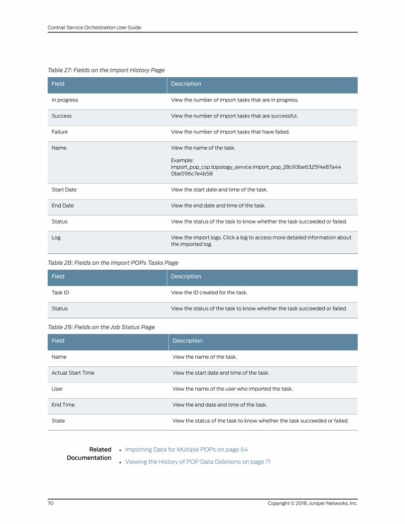
Table 27: Fields on the Import History Page
DescriptionField
View the number of import tasks that are in progress.In progress
View the number of import tasks that are successful.Success
View the number of import tasks that have failed.Failure
View the name of the task.
Example:import_pop_csp.topology_service.import_pop_28c93be6325f4e87a440be096c7e4b58
Name
View the start date and time of the task.Start Date
View the end date and time of the task.End Date
View the status of the task to knowwhether the task succeeded or failed.Status
View the import logs. Click a log to access more detailed information aboutthe imported log.
Log
Table 28: Fields on the Import POPs Tasks Page
DescriptionField
View the ID created for the task.Task ID
View the status of the task to knowwhether the task succeeded or failed.Status
Table 29: Fields on the Job Status Page
DescriptionField
View the name of the task.Name
View the start date and time of the task.Actual Start Time
View the name of the user who imported the task.User
View the end date and time of the task.End Time
View the status of the task to knowwhether the task succeeded or failed.State
RelatedDocumentation
Importing Data for Multiple POPs on page 64•
• Viewing the History of POP Data Deletions on page 71
Copyright © 2018, Juniper Networks, Inc.70
Contrail Service Orchestration User Guide
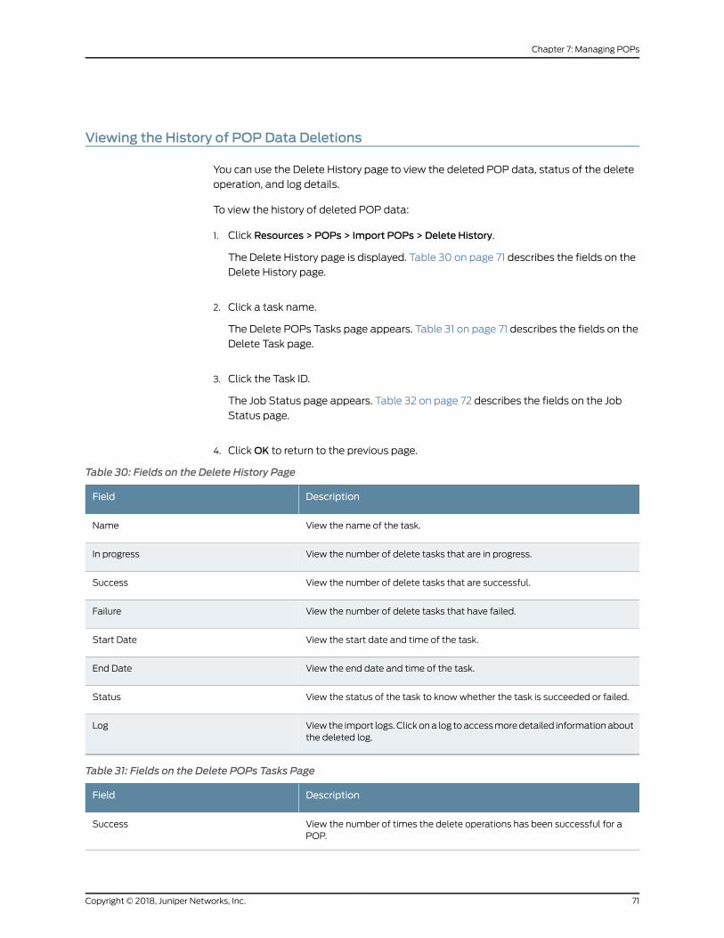
Viewing the History of POP Data Deletions
You can use the Delete History page to view the deleted POP data, status of the delete
operation, and log details.
To view the history of deleted POP data:
1. Click Resources > POPs > Import POPs > Delete History.
The Delete History page is displayed. Table 30 on page 71 describes the fields on the
Delete History page.
2. Click a task name.
The Delete POPs Tasks page appears. Table 31 on page 71 describes the fields on the
Delete Task page.
3. Click the Task ID.
The Job Status page appears. Table 32 on page 72 describes the fields on the Job
Status page.
4. ClickOK to return to the previous page.
Table 30: Fields on the Delete History Page
DescriptionField
View the name of the task.Name
View the number of delete tasks that are in progress.In progress
View the number of delete tasks that are successful.Success
View the number of delete tasks that have failed.Failure
View the start date and time of the task.Start Date
View the end date and time of the task.End Date
View the status of the task to knowwhether the task is succeeded or failed.Status
View the import logs. Clickona log toaccessmoredetailed informationaboutthe deleted log.
Log
Table 31: Fields on the Delete POPs Tasks Page
DescriptionField
View the number of times the delete operations has been successful for aPOP.
Success
71Copyright © 2018, Juniper Networks, Inc.
Chapter 7: Managing POPs
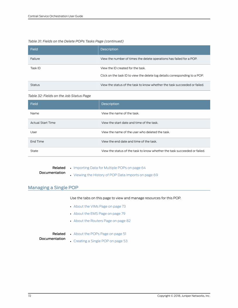
Table 31: Fields on the Delete POPs Tasks Page (continued)
DescriptionField
View the number of times the delete operations has failed for a POP.Failure
View the ID created for the task.
Click on the task ID to view the delete log details corresponding to a POP.
Task ID
View the status of the task to knowwhether the task succeeded or failed.Status
Table 32: Fields on the Job Status Page
DescriptionField
View the name of the task.Name
View the start date and time of the task.Actual Start Time
View the name of the user who deleted the task.User
View the end date and time of the task.End Time
View the status of the task to knowwhether the task succeeded or failed.State
RelatedDocumentation
Importing Data for Multiple POPs on page 64•
• Viewing the History of POP Data Imports on page 69
Managing a Single POP
Use the tabs on this page to view andmanage resources for this POP.
• About the VIMs Page on page 73
• About the EMS Page on page 79
• About the Routers Page on page 82
RelatedDocumentation
About the POPs Page on page 51•
• Creating a Single POP on page 53
Copyright © 2018, Juniper Networks, Inc.72
Contrail Service Orchestration User Guide
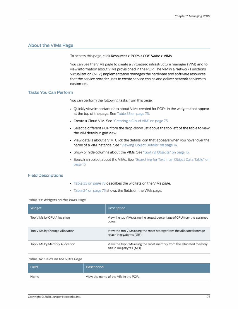
About the VIMs Page
To access this page, click Resources > POPs > POPName > VIMs.
You can use the VIMs page to create a virtualized infrastructure manager (VIM) and to
view information about VIMs provisioned in the POP. The VIM in a Network Functions
Virtualization (NFV) implementation manages the hardware and software resources
that the service provider uses to create service chains and deliver network services to
customers.
Tasks You Can Perform
You can perform the following tasks from this page:
• Quickly view important data about VIMs created for POPs in the widgets that appear
at the top of the page. See Table 33 on page 73.
• Create a Cloud VIM. See “Creating a Cloud VIM” on page 75.
• Select a different POP from the drop-down list above the top left of the table to view
the VIM details in grid view.
• View details about a VIM. Click the details icon that appears when you hover over the
name of a VIM instance. See “Viewing Object Details” on page 14.
• Show or hide columns about the VIMs. See “Sorting Objects” on page 15.
• Search an object about the VIMs. See “Searching for Text in an Object Data Table” on
page 15.
Field Descriptions
• Table 33 on page 73 describes the widgets on the VIMs page.
• Table 34 on page 73 shows the fields on the VIMs page.
Table 33:Widgets on the VIMs Page
DescriptionWidget
Viewthe topVIMsusing the largestpercentageofCPUfromtheassignedcores.
Top VIMs by CPU Allocation
View the top VIMs using the most storage from the allocated storagespace in gigabytes (GB).
Top VIMs by Storage Allocation
View the top VIMs using the most memory from the allocatedmemorysize in megabytes (MB).
Top VIMs by Memory Allocation
Table 34: Fields on the VIMs Page
DescriptionField
View the name of the VIM in the POP.Name
73Copyright © 2018, Juniper Networks, Inc.
Chapter 7: Managing POPs
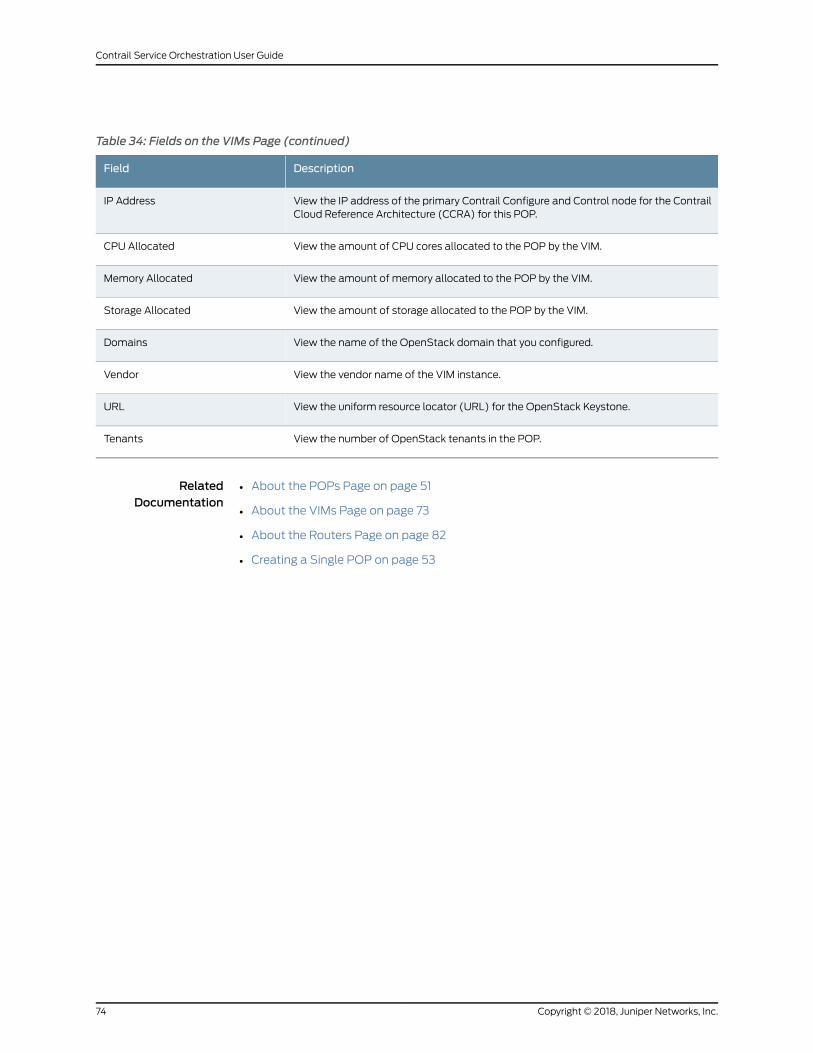
Table 34: Fields on the VIMs Page (continued)
DescriptionField
View the IP address of the primary Contrail Configure and Control node for the ContrailCloud Reference Architecture (CCRA) for this POP.
IP Address
View the amount of CPU cores allocated to the POP by the VIM.CPU Allocated
View the amount of memory allocated to the POP by the VIM.Memory Allocated
View the amount of storage allocated to the POP by the VIM.Storage Allocated
View the name of the OpenStack domain that you configured.Domains
View the vendor name of the VIM instance.Vendor
View the uniform resource locator (URL) for the OpenStack Keystone.URL
View the number of OpenStack tenants in the POP.Tenants
RelatedDocumentation
About the POPs Page on page 51•
• About the VIMs Page on page 73
• About the Routers Page on page 82
• Creating a Single POP on page 53
Copyright © 2018, Juniper Networks, Inc.74
Contrail Service Orchestration User Guide
Creating a Cloud VIM
You can use the VIMs page to create virtualized infrastructuremanagers (VIMs) for each
POP in the network. You create one VIM object for each POP in your network. Although
the Contrail Cloud Reference Architecture (CCRA) provides a VIM, when you create a
VIM you can specify several Contrail OpenStack settings. See Table 35 on page 76.
You can only create a VIM for a centralized deployment. A distributed deployment has
a default VIM that is created when the deployment is installed.
There are two authentication methods, namely, CSO Keystone (Central Keystone)
authentication and independent VIM Instances’s keystone (also known as regional
keystone) authentication. Customers can authenticate and authorize their own system
through OpenStack. Customers have to configure service profiles as a part of VIM and
associate it with a tenant.
For example, consider ABC as a service provider and customer-a as the tenant for ABC.
The workflow for associating the service profile with the tenant is listed below:
1. The cspadmin configures the POP (vim-instance and domain creations) along with
vim-service-profiles when configuring the vim-instance. The vim-service-profiles
contains the respective VIM’s infra tenant details.
2. Configure ABC data center as a VIM.
3. ABCadmin configures customer-a alongwith service-profile-name. This enables VIM
microservice to map customer-a to equivalent infra tenant as specified in
service-profile-name.
4. ABC admin, ABC tenant details, customer-a tenant, and customer-a account details
are present in CSO Keystone (Central Keystone), while infra tenant details that are
available as part of vim-service-profile is present only in regional keystone.
5. Whencreating a service, customer-a instantiates anetwork service. The customer-a’s
request is received at NSOwith customer-a’s authentication token from the regional
VIM keystone.
6. Based on tenant-name customer-a, the VIM region maps to “admin” infra tenant,
becausewhenconfiguring “customer-a ” tenant, the service-profile-namewithadmin
was provided.
7. VIM regional microservice can now use the infra tenant for its service instantiation
activities.
To create a VIM in the cloud:
1. Click Resources > POPs > POPName > VIMs.
75Copyright © 2018, Juniper Networks, Inc.
Chapter 7: Managing POPs
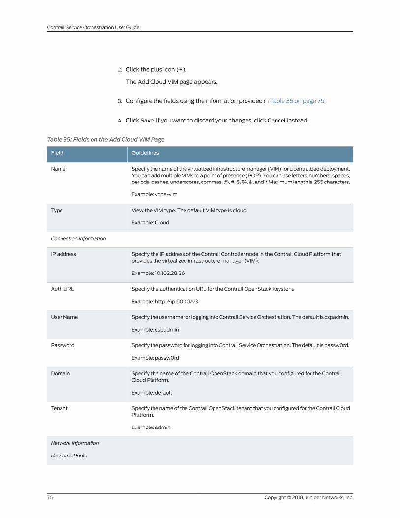
2. Click the plus icon (+).
The Add Cloud VIM page appears.
3. Configure the fields using the information provided in Table 35 on page 76.
4. Click Save. If you want to discard your changes, click Cancel instead.
Table 35: Fields on the Add Cloud VIM Page
GuidelinesField
Specify thenameof thevirtualized infrastructuremanager (VIM) for acentralizeddeployment.YoucanaddmultipleVIMs toapointofpresence(POP).Youcanuse letters, numbers, spaces,periods, dashes, underscores, commas,@,#,$,%,&, and*.Maximumlength is 255characters.
Example: vcpe-vim
Name
View the VIM type. The default VIM type is cloud.
Example: Cloud
Type
Connection Information
Specify the IP address of the Contrail Controller node in the Contrail Cloud Platform thatprovides the virtualized infrastructure manager (VIM).
Example: 10.102.28.36
IP address
Specify the authentication URL for the Contrail OpenStack Keystone.
Example: http://ip:5000/v3
Auth URL
Specify theusernamefor logging intoContrail ServiceOrchestration.Thedefault is cspadmin.
Example: cspadmin
User Name
Specify thepassword for logging intoContrail ServiceOrchestration. Thedefault is passw0rd.
Example: passw0rd
Password
Specify the name of the Contrail OpenStack domain that you configured for the ContrailCloud Platform.
Example: default
Domain
Specify the nameof theContrail OpenStack tenant that you configured for theContrail CloudPlatform.
Example: admin
Tenant
Network Information
Resource Pools
Copyright © 2018, Juniper Networks, Inc.76
Contrail Service Orchestration User Guide
Table 35: Fields on the Add Cloud VIM Page (continued)
GuidelinesField
Specify a resource pool name and the corresponding compute zone, which is a group ofcompute nodes. You configure compute zones as availability zones in Contrail OpenStack.Thedefault availability zone isNova, andyoucan run thenovaavailability-zone-list commandon the Contrail controller node to view a list of available zones.
Resource Pool
Specify a resource pool, which identifies the location in which the virtual network functions(VNFs) are implemented. You can use an unlimited number of alphanumeric characters,including special characters.
Example: north-east.
Resource Pool Name
Specify the availability zone in Contrail OpenStack in which the virtual machines for networkservices reside. The default availability zone is nova.
You can run the nova availability-zone-list command on the Contrail OpenStack to find thelist of available zones.
Example: nova
Compute Zone
Specify whether to use an existing virtual network in Contrail OpenStack or to create a newone.
• yes—Import the named virtual network from Contrail OpenStack.
• no—Create a virtual network in Contrail OpenStack with the specified name.
Does Management NetworkExists?
Specify the name of the existing network in Contrail or of the new network that you want tocreate in Contrail.
Example: mgmt-net
Management Network Name
Management NetworkInformation
Specify one or more route targets for the management network to be created in Contrail
Example: 64512:10000.
Route Target
Specify one or more prefixes that define the subnets for the Contrail Compute nodes. Youcan use an IPv4 address.
Example: 192.0.2.0/24.
Subnet
Internet Network Information
Specify the name of the Internet network.
Example: int-net
Network Name
Select to add a new Internet connection for the VIM in Contrail OpenStack.Does Exist?
77Copyright © 2018, Juniper Networks, Inc.
Chapter 7: Managing POPs
Table 35: Fields on the Add Cloud VIM Page (continued)
GuidelinesField
Select the route target for the internet network in Contrail.
Example: 64512:10000.
Route Target
Select the prefix that defines the subnet for the Contrail Compute nodes.
You can use an IPv4 address.
Example: 192.0.2.0/24.
Subnet
Service Profile Information
Specify the name of the service profile in a VIM instance.
Example: vim-service-profile
Profile Name
Specify the infra tenant for whom you want to assign the service profile.
Example: test-tenant
Tenant Name
Specify the Infra domain name.
Example: Default
Domain Name
Specify the username of the tenant.
Example: admin
User Name
Specify the password for the tenant user.
Example: password123
Password
If you use a dedicated OpenStack Keystone for Contrail Service Orchestration, specify thename of the default service profile. If you do not specify a service profile when you configurethe tenant, Contrail Service Orchestration uses the default profile to authenticate the tenant.
Example: default-service-profile
Default Service Profile
NOTE: Infra Tenants such as admin is available only in Regional Keystone
and not in CSO Keystone (Central Keystone).
RelatedDocumentation
About the Routers Page on page 82•
• Configuring Devices on page 85
• Creating an EMS on page 80
Copyright © 2018, Juniper Networks, Inc.78
Contrail Service Orchestration User Guide
About the EMS Page
To access this page, click Resources > POPs > POPName > EMS.
You can use the EMS page to create an element management system and to view
information about an EMS configured in your POP. You need to configure your Junos
Space Virtual Appliance with the Administration Portal so that the virtual appliance can
communicate with other components in your deployment.
Tasks You Can Perform
You can perform the following tasks from this page:
• Create an EMS. See “Creating an EMS” on page 80.
• Change the Junos Space Password. See “Changing the Junos Space Virtual Appliance
Password” on page 81.
• Select a different POP from the drop-down list above the top left of the table to view
details about an EMS in grid view.
• View details about an EMS. Click the details icon that appears when you hover over
the name of an EMS application. See “Viewing Object Details” on page 14.
• Show or hide columns about an EMS. See “Sorting Objects” on page 15.
• Search an object about an EMS. See “Searching for Text in an Object Data Table” on
page 15.
Field Descriptions
Table 36 on page 79 shows the fields on the EMS page.
Table 36: Fields on the EMS Page
DescriptionField
View the name of the EMS application.
Example: Junos Space
Name
Viewthe IPaddressof the JunosSpaceWebuser interface (UI). For a redundantContrailService Orchestration, configure the IP address of theWeb UI for the primary JunosSpace Virtual Appliance.
Example: 192.0.2.3
IP Address
View the vendor name for the EMS.
Example: Juniper Networks
Vendor
RelatedDocumentation
About the POPs Page on page 51•
• Creating a Single POP on page 53
79Copyright © 2018, Juniper Networks, Inc.
Chapter 7: Managing POPs
• About the VIMs Page on page 73
• About the Routers Page on page 82
Creating an EMS
Youcanuse theEMSManagementpage toconfigure theprimary instanceofeachelement
management system (EMS) that you use for the Cloud CPE Centralized Deployment
Model. Administration Portal automatically adds an object for the EMS, using the name
that you specify when you deploy the Junos Space Virtual Appliance.
Verify that the VIMManagement page displays the virtualized infrastructure managers
(VIMs).
To create an EMS:
1. Click Resources > POPs > POPName > EMS.
2. Click the plus (+) icon.
The Add EMS page appears.
3. Complete theconfigurationaccording to theguidelinesprovided inTable37onpage80.
4. Click Save. If you want to discard your changes, click Cancel instead.
Table 37: Fields on the Add EMS Page
GuidelinesField
Nameof theEMS.This field isauto-populatedwith thenamethat youspecifiedwhenyoudeployedthe Junos Space Virtual Appliance.
Example: Junos Space
Name
Specify the IP address of the Junos SpaceWeb user interface (UI).
For a redundant Contrail Service Orchestration, configure the IP address of theWeb UI for theprimary Junos Space Virtual Appliance.
Example: 192.0.2.3.
IP
Specify the vendor for the EMS.
Example: Juniper Networks
Vendor
Specify the version number of the EMS. The default version is 15.1.
Example: 15.1
Version
Specify the authentication URL for the EMS application.Authentication URL
Copyright © 2018, Juniper Networks, Inc.80
Contrail Service Orchestration User Guide
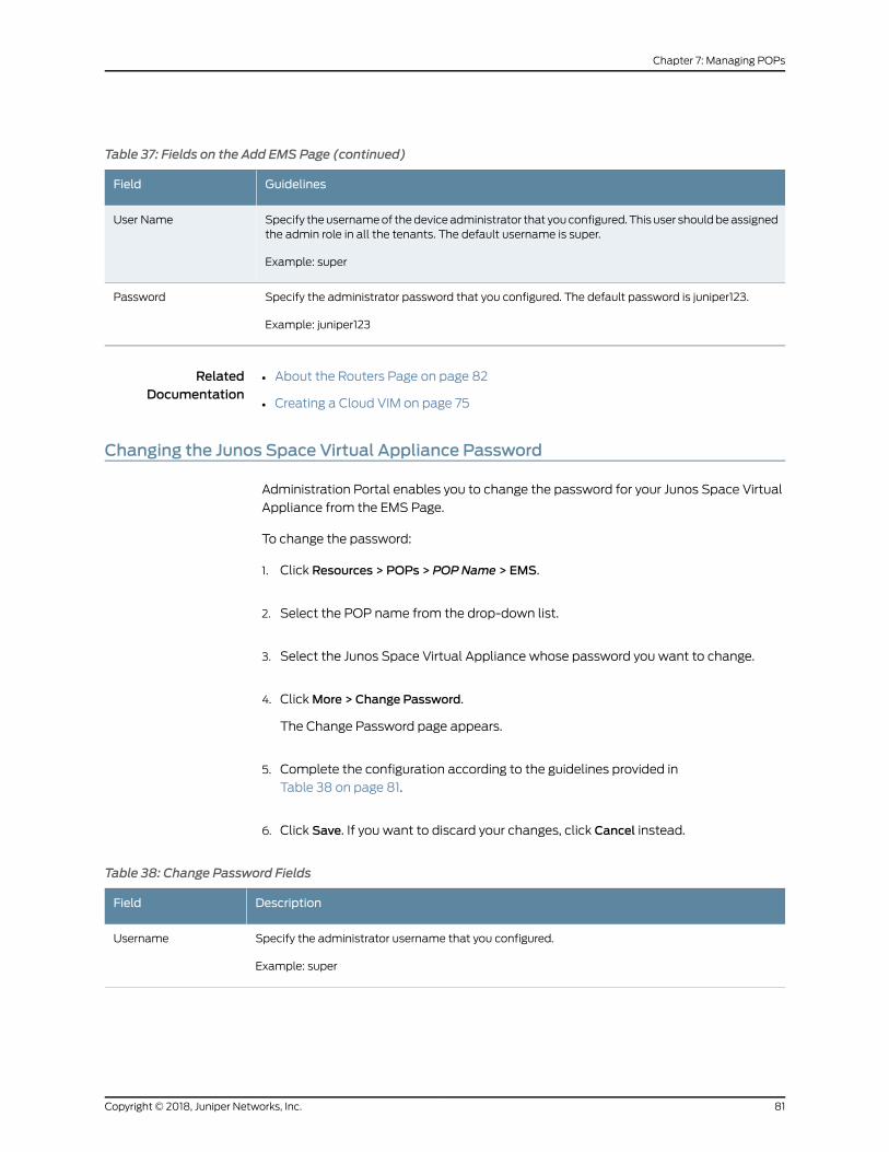
Table 37: Fields on the Add EMS Page (continued)
GuidelinesField
Specify theusernameof thedeviceadministrator that youconfigured.This user shouldbeassignedthe admin role in all the tenants. The default username is super.
Example: super
User Name
Specify the administrator password that you configured. The default password is juniper123.
Example: juniper123
Password
RelatedDocumentation
About the Routers Page on page 82•
• Creating a Cloud VIM on page 75
Changing the Junos Space Virtual Appliance Password
Administration Portal enables you to change the password for your Junos Space Virtual
Appliance from the EMS Page.
To change the password:
1. Click Resources > POPs > POPName > EMS.
2. Select the POP name from the drop-down list.
3. Select the Junos Space Virtual Appliance whose password you want to change.
4. ClickMore > Change Password.
The Change Password page appears.
5. Complete the configuration according to the guidelines provided in
Table 38 on page 81.
6. Click Save. If you want to discard your changes, click Cancel instead.
Table 38: Change Password Fields
DescriptionField
Specify the administrator username that you configured.
Example: super
Username
81Copyright © 2018, Juniper Networks, Inc.
Chapter 7: Managing POPs

Table 38: Change Password Fields (continued)
DescriptionField
Specify the new password that you want to configure.
You can choose a password that is at least eight characters long and contains characters from atleast three of the following four character classes: uppercase letters, lowercase letters, numbers (0through 9), and special characters.
Password
RelatedDocumentation
About the EMS Page on page 79•
• Creating an EMS on page 80
About the Routers Page
To access this page, click Resources > POPs > POPName > Routers.
You can use the Routers page to view information about the gateway router configured
in the POP and to create and configure physical network elements (PNEs) associated
with a specific customer site. A PNE is a device in the network that you can provision and
configure through Contrail Service Orchestration.
Tasks You Can Perform
You can perform the following tasks from this page:
• Create a device. See “Creating Devices” on page 83.
• Configure a device. See “Configuring Devices” on page 85.
• Select a different POP from the drop-down list above the top left of the table to view
router details in grid view.
• View details about a router. Click the details icon that appears when you hover over
the name of a router application. See “Viewing Object Details” on page 14.
• Show or hide columns about the routers. See “Sorting Objects” on page 15.
• Search an object about the router. See “Searching for Text in an Object Data Table”
on page 15.
• Delete a device. See “Deleting Objects” on page 14.
Field Descriptions
Table 39 on page 82 describes the fields on the Routers page.
Table 39: Fields on the Routers Page
DescriptionField
View the name of the device configured in the POP.
Example: blue_device
Name
Copyright © 2018, Juniper Networks, Inc.82
Contrail Service Orchestration User Guide
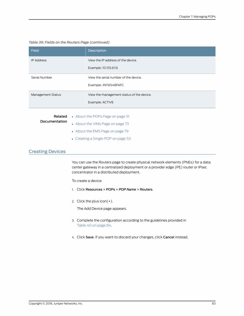
Table 39: Fields on the Routers Page (continued)
DescriptionField
View the IP address of the device.
Example: 10.155.67.6
IP Address
View the serial number of the device.
Example: JN116548FAFC
Serial Number
View themanagement status of the device.
Example: ACTIVE
Management Status
RelatedDocumentation
About the POPs Page on page 51•
• About the VIMs Page on page 73
• About the EMS Page on page 79
• Creating a Single POP on page 53
Creating Devices
You can use the Routers page to create physical network elements (PNEs) for a data
center gateway in a centralized deployment or a provider edge (PE) router or IPsec
concentrator in a distributed deployment.
To create a device:
1. Click Resources > POPs > POPName > Routers.
2. Click the plus icon(+).
The Add Device page appears.
3. Complete the configuration according to the guidelines provided in
Table 40 on page 84.
4. Click Save. If you want to discard your changes, click Cancel instead.
83Copyright © 2018, Juniper Networks, Inc.
Chapter 7: Managing POPs
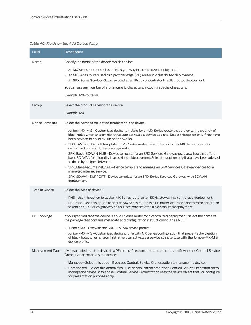
Table 40: Fields on the Add Device Page
DescriptionField
Specify the name of the device, which can be:
• AnMX Series router used as an SDN gateway in a centralized deployment.
• AnMX Series router used as a provider edge (PE) router in a distributed deployment.
• An SRX Series Services Gateway used as an IPsec concentrator in a distributed deployment.
You can use any number of alphanumeric characters, including special characters.
Example: MX-router-10
Name
Select the product series for the device.
Example: MX
Family
Select the name of the device template for the device:
• Juniper-MX-MIS—Customized device template for an MX Series router that prevents the creation ofblack holes when an administrative user activates a service at a site. Select this option only if you havebeen advised to do so by Juniper Networks.
• SDN-GW-MX—Default template for MX Series router. Select this option for MX Series routers incentralized and distributed deployments.
• SRX_Basic_SDWAN_HUB—Device template for an SRX Services Gateway used as a hub that offersbasicSD-WANfunctionality inadistributeddeployment. Select this optiononly if youhavebeenadvisedto do so by Juniper Networks.
• SRX_Managed_Internet_CPE—Device template to manage an SRX Services Gateway devices for amanaged internet service.
• SRX_SDWAN_SUPPORT—Device template for an SRX Series Services Gateway with SDWANdeployment.
Device Template
Select the type of device:
• PNE—Use this option to add an MX Series router as an SDN gateway in a centralized deployment.
• PE/IPsec—Use this option to add an MX Series router as a PE router, an IPsec concentrator or both, orto add an SRX Series gateway as an IPsec concentrator in a distributed deployment.
Type of Device
If you specified that the device is an MX Series router for a centralized deployment, select the name ofthe package that contains metadata and configuration instructions for the PNE:
• Juniper-MX—Use with the SDN-GW-MX device profile.
• Juniper-MX-MIS—Customized device profile with MX Series configuration that prevents the creationof black holes when an administrative user activates a service at a site. Use with the Juniper-MX-MISdevice profile.
PNE package
If you specified that the device is a PE router, IPsec concentrator, or both, specify whether Contrail ServiceOrchestration manages the device:
• Managed—Select this option if you use Contrail Service Orchestration to manage the device.
• Unmanaged—Select this option if you use an application other than Contrail Service Orchestration tomanage thedevice. In this case, Contrail ServiceOrchestrationuses thedeviceobject that youconfigurefor presentation purposes only.
ManagementType
Copyright © 2018, Juniper Networks, Inc.84
Contrail Service Orchestration User Guide
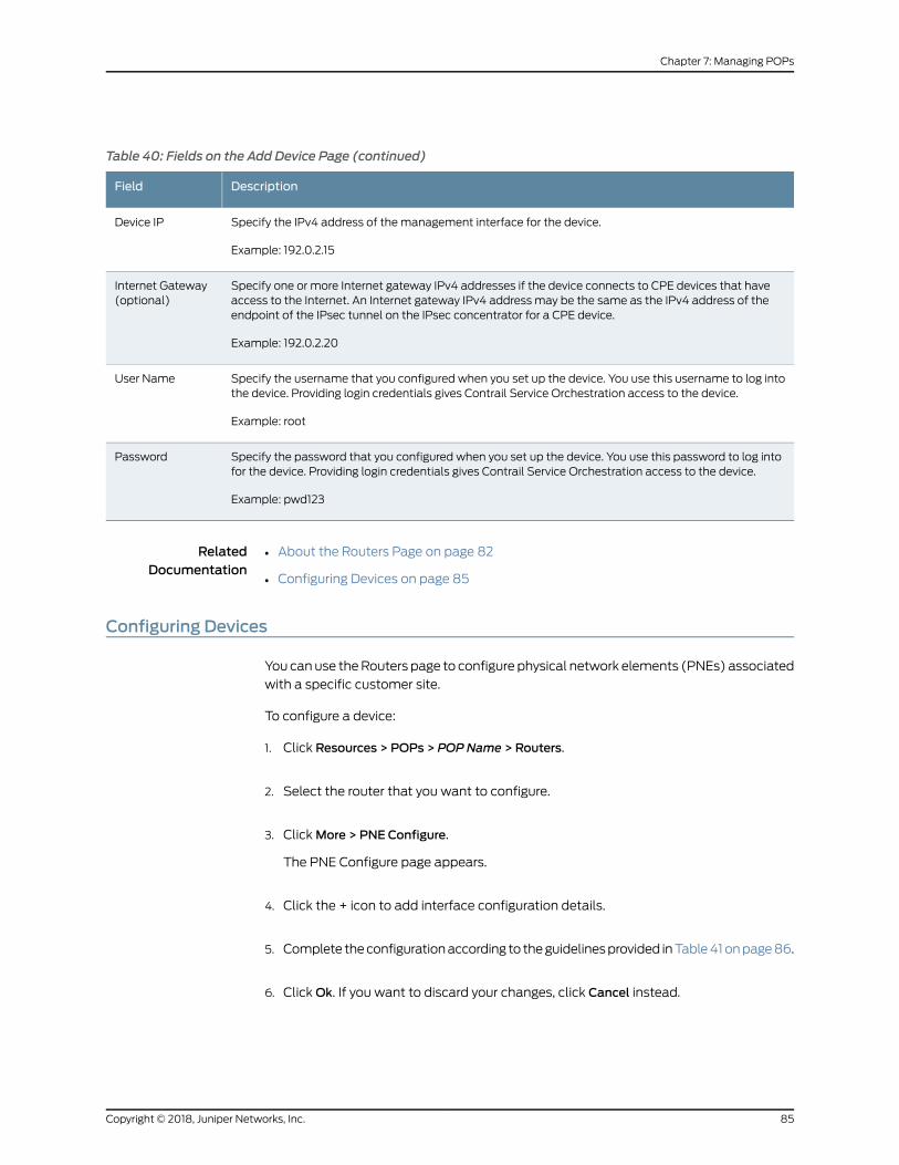
Table 40: Fields on the Add Device Page (continued)
DescriptionField
Specify the IPv4 address of the management interface for the device.
Example: 192.0.2.15
Device IP
Specify one or more Internet gateway IPv4 addresses if the device connects to CPE devices that haveaccess to the Internet. An Internet gateway IPv4 address may be the same as the IPv4 address of theendpoint of the IPsec tunnel on the IPsec concentrator for a CPE device.
Example: 192.0.2.20
Internet Gateway(optional)
Specify the username that you configured when you set up the device. You use this username to log intothe device. Providing login credentials gives Contrail Service Orchestration access to the device.
Example: root
User Name
Specify the password that you configured when you set up the device. You use this password to log intofor the device. Providing login credentials gives Contrail Service Orchestration access to the device.
Example: pwd123
Password
RelatedDocumentation
About the Routers Page on page 82•
• Configuring Devices on page 85
Configuring Devices
You canuse theRouters page to configure physical network elements (PNEs) associated
with a specific customer site.
To configure a device:
1. Click Resources > POPs > POPName > Routers.
2. Select the router that you want to configure.
3. ClickMore > PNE Configure.
The PNE Configure page appears.
4. Click the + icon to add interface configuration details.
5. Complete theconfigurationaccording to theguidelinesprovided inTable41onpage86.
6. ClickOk. If you want to discard your changes, click Cancel instead.
85Copyright © 2018, Juniper Networks, Inc.
Chapter 7: Managing POPs
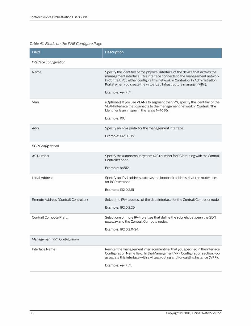
Table 41: Fields on the PNE Configure Page
DescriptionField
Interface Configuration
Specify the identifier of the physical interface of the device that acts as themanagement interface. This interface connects to the management networkin Contrail. You either configure this network in Contrail or in AdministrationPortal when you create the virtualized infrastructure manager (VIM).
Example: xe-1/1/1
Name
(Optional) If you use VLANs to segment the VPN, specify the identifier of theVLAN interface that connects to the management network in Contrail. Theidentifier is an integer in the range 1–4096.
Example: 100
Vlan
Specify an IPv4 prefix for the management interface.
Example: 192.0.2.15
Addr
BGP Configuration
Specify theautonomoussystem(AS)number forBGP routingwith theContrailController node.
Example: 64512
AS Number
Specify an IPv4 address, such as the loopback address, that the router usesfor BGP sessions.
Example: 192.0.2.15
Local Address
Select the IPv4 address of the data interface for the Contrail Controller node.
Example: 192.0.2.25.
Remote Address (Contrail Controller)
Select one or more IPv4 prefixes that define the subnets between the SDNgateway and the Contrail Compute nodes.
Example: 192.0.2.0/24.
Contrail Compute Prefix
Management VRF Configuration
Reenter themanagement interface identifier that you specified in the InterfaceConfiguration Name field. In theManagement VRF Configuration section, youassociate this interface with a virtual routing and forwarding instance (VRF).
Example: xe-1/1/1.
Interface Name
Copyright © 2018, Juniper Networks, Inc.86
Contrail Service Orchestration User Guide
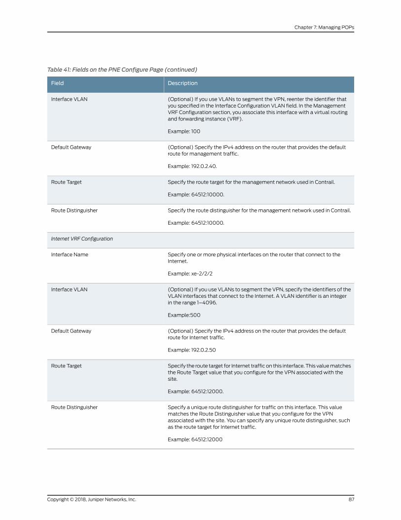
Table 41: Fields on the PNE Configure Page (continued)
DescriptionField
(Optional) If you use VLANs to segment the VPN, reenter the identifier thatyou specified in the Interface Configuration VLAN field. In the ManagementVRF Configuration section, you associate this interface with a virtual routingand forwarding instance (VRF).
Example: 100
Interface VLAN
(Optional) Specify the IPv4 address on the router that provides the defaultroute for management traffic.
Example: 192.0.2.40.
Default Gateway
Specify the route target for the management network used in Contrail.
Example: 64512:10000.
Route Target
Specify the route distinguisher for themanagement network used in Contrail.
Example: 64512:10000.
Route Distinguisher
Internet VRF Configuration
Specify one or more physical interfaces on the router that connect to theInternet.
Example: xe-2/2/2
Interface Name
(Optional) If you use VLANs to segment the VPN, specify the identifiers of theVLAN interfaces that connect to the Internet. A VLAN identifier is an integerin the range 1–4096.
Example:500
Interface VLAN
(Optional) Specify the IPv4 address on the router that provides the defaultroute for Internet traffic.
Example: 192.0.2.50
Default Gateway
Specify the route target for Internet traffic on this interface. This valuematchesthe Route Target value that you configure for the VPN associated with thesite.
Example: 64512:12000.
Route Target
Specify a unique route distinguisher for traffic on this interface. This valuematches the Route Distinguisher value that you configure for the VPNassociated with the site. You can specify any unique route distinguisher, suchas the route target for Internet traffic.
Example: 64512:12000
Route Distinguisher
87Copyright © 2018, Juniper Networks, Inc.
Chapter 7: Managing POPs
You can also configure the devices from the POPs landing page.
To configure a device:
1. Select Resources > POPs > Pop-Name.
The Pop-Name page appears.
2. Click the Routers tab.
3. Select the device that you want to configure and click the Configure Device button.
TheStage2Config pageappears. This page is dynamically renderedbasedon stage-2
configuration specified in the device profile.
4. Enter the configuration data on the page.
5. Click Save to save the configuration.
A confirmationmessage is displayed and the deployment status changes to pending
deployment.
6. Click Deploy to save and deploy the configuration.
Aconfirmationmessage isdisplayed indicating that the job is createdandsubsequently
that the job was successful. You can click Deploy History to view the job logs.
7. Click Cancel to go back to the Pop-Name page.
RelatedDocumentation
About the Routers Page on page 82•
• Creating Devices on page 83
View the History of Device Data Deletions
You can use the Delete History page to view the deleted device data, status of the delete
operation, and log details.
To view the history of deleted device data:
1. Click Resources > POPs > POPName > Routers >More > Delete History.
The Delete History page is displayed. Table 42 on page 89 describes the fields on the
Delete History page.
2. Click a task name.
The Delete Device Tasks page appears. Table 43 on page 89 describes the fields on
the Delete Task page.
Copyright © 2018, Juniper Networks, Inc.88
Contrail Service Orchestration User Guide
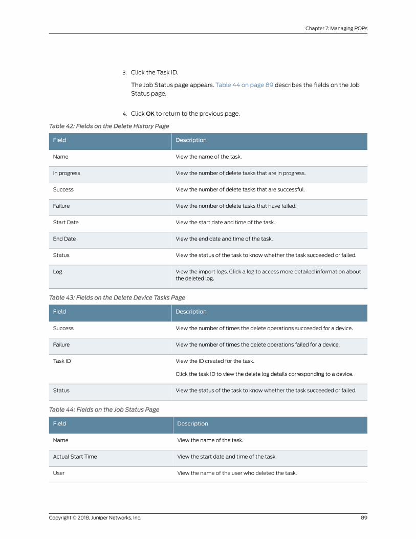
3. Click the Task ID.
The Job Status page appears. Table 44 on page 89 describes the fields on the Job
Status page.
4. ClickOK to return to the previous page.
Table 42: Fields on the Delete History Page
DescriptionField
View the name of the task.Name
View the number of delete tasks that are in progress.In progress
View the number of delete tasks that are successful.Success
View the number of delete tasks that have failed.Failure
View the start date and time of the task.Start Date
View the end date and time of the task.End Date
View the status of the task to knowwhether the task succeeded or failed.Status
View the import logs. Click a log to access more detailed information aboutthe deleted log.
Log
Table 43: Fields on the Delete Device Tasks Page
DescriptionField
View the number of times the delete operations succeeded for a device.Success
View the number of times the delete operations failed for a device.Failure
View the ID created for the task.
Click the task ID to view the delete log details corresponding to a device.
Task ID
View the status of the task to knowwhether the task succeeded or failed.Status
Table 44: Fields on the Job Status Page
DescriptionField
View the name of the task.Name
View the start date and time of the task.Actual Start Time
View the name of the user who deleted the task.User
89Copyright © 2018, Juniper Networks, Inc.
Chapter 7: Managing POPs
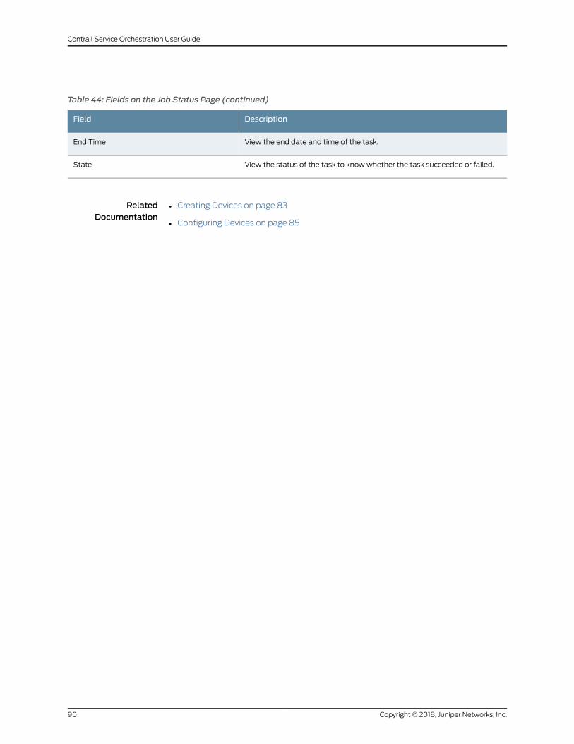
Table 44: Fields on the Job Status Page (continued)
DescriptionField
View the end date and time of the task.End Time
View the status of the task to knowwhether the task succeeded or failed.State
RelatedDocumentation
• Creating Devices on page 83
• Configuring Devices on page 85
Copyright © 2018, Juniper Networks, Inc.90
Contrail Service Orchestration User Guide
CHAPTER 8
Managing Devices
• About the Tenant Devices Page on page 91
• About the Cloud Hub Devices Page on page 94
• Managing a Tenant Device on page 96
• Managing a Cloud Hub Device on page 97
• Device Redundancy Support Overview on page 98
• Viewing the History of Tenant Device Activation Logs on page 100
• Viewing the History of Cloud Hub Device Activation Logs on page 102
• Adding a Cloud Hub Device on page 103
• Rebooting a CPE Device on page 105
About the Tenant Devices Page
To access this page, click Resources > Tenant Devices.
You can use the Tenant Devices page to view the list of available CPE devices in the
service provider network. You can also view information about each CPE device in the
network.
Tasks You Can Perform
You can perform the following tasks from this page:
• Quickly view activation data created for CPEs in the widgets that appear at the top of
the page. See Table 45 on page 92.
• View the history of activation data. See Viewing the History of Activation Data Uploads.
• View the history of deactivation requests. See Viewing the History of Deactivation
Requests.
• Reboot a CPE device. See “Rebooting a CPE Device” on page 105.
• View Stage-1 configuration. Click Resources > Tenant Devices >Device-Name > Stage
1 Config to view the stage-1 configuration for the device.
• View the device audit logs. Click Resources > Tenant Devices >Device-Name > Device
Audit Logs to view the audit logs for the device.
91Copyright © 2018, Juniper Networks, Inc.
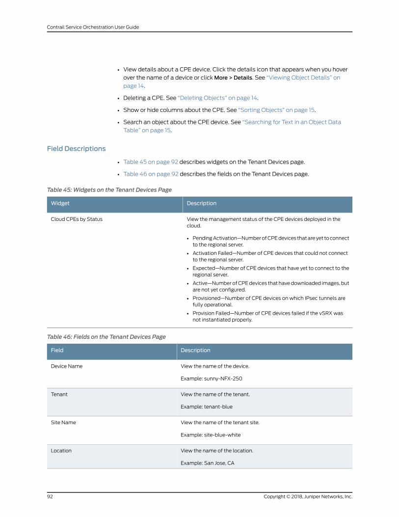
• View details about a CPE device. Click the details icon that appears when you hover
over the name of a device or clickMore > Details. See “Viewing Object Details” on
page 14.
• Deleting a CPE. See “Deleting Objects” on page 14.
• Show or hide columns about the CPE. See “Sorting Objects” on page 15.
• Search an object about the CPE device. See “Searching for Text in an Object Data
Table” on page 15.
Field Descriptions
• Table 45 on page 92 describes widgets on the Tenant Devices page.
• Table 46 on page 92 describes the fields on the Tenant Devices page.
Table 45:Widgets on the Tenant Devices Page
DescriptionWidget
View themanagement status of the CPE devices deployed in thecloud.
• PendingActivation—NumberofCPEdevices thatareyet toconnectto the regional server.
• Activation Failed—Number of CPE devices that could not connectto the regional server.
• Expected—Number of CPE devices that have yet to connect to theregional server.
• Active—Number ofCPEdevices that havedownloaded images, butare not yet configured.
• Provisioned—Number of CPE devices on which IPsec tunnels arefully operational.
• Provision Failed—Number of CPE devices failed if the vSRX wasnot instantiated properly.
Cloud CPEs by Status
Table 46: Fields on the Tenant Devices Page
DescriptionField
View the name of the device.
Example: sunny-NFX-250
Device Name
View the name of the tenant.
Example: tenant-blue
Tenant
View the name of the tenant site.
Example: site-blue-white
Site Name
View the name of the location.
Example: San Jose, CA
Location
Copyright © 2018, Juniper Networks, Inc.92
Contrail Service Orchestration User Guide
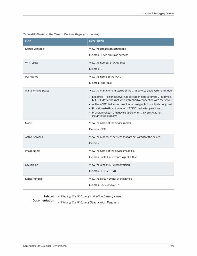
Table 46: Fields on the Tenant Devices Page (continued)
DescriptionField
View the latest status message.
Example: IPsec provision success
Status Message
View the number of WAN links.
Example: 2
WAN Links
View the name of the POP.
Example: pop_blue
POP Name
View themanagement status of the CPE devices deployed in the cloud.
• Expected—Regional server has activation details for the CPE device,but CPE device has not yet established a connection with the server.
• Active—CPEdevicehasdownloaded images, but is not yet configured.
• Provisioned—IPsec tunnel on NFX250 device is operational.
• Provision Failed—CPE device failed when the vSRXwas notinstantiated properly.
Management Status
View the name of the device model.
Example: NFX
Model
View the number of services that are activated for the device.
Example: 3
Active Services
View the name of the device image file.
Example: install_nfx_fmpm_agent_1_0.sh
Image Name
View the Junos OS Release version.
Example: 15.1X49-D40
OS Version
View the serial number of the device.
Example: DD0416AA0117
Serial Number
RelatedDocumentation
Viewing the History of Activation Data Uploads•
• Viewing the History of Deactivation Requests
93Copyright © 2018, Juniper Networks, Inc.
Chapter 8: Managing Devices
About the Cloud Hub Devices Page
To access this page, select Resources > Cloud Hub Devices.
You can use the Cloud Hub Devices page to view the list of cloud hub devices that are
owned by the administrator in the service provider network. You can also create new
cloudhubdevices, delete existing cloudhubdevices, andviewdetailed informationabout
each cloud hub device in the network. You can add either an MX Series router or an SRX
Series services gateway as a cloud hub (SD-WAN) device in a hub-and-spoke topology.
Contrail Service Orchestration (CSO) uses the cloud hub devices as SD-WAN hubs to
setup tunnels and provision site-to-site or site-to-hub traffic. All other configurations
such as Internet breakout, hubmeshing, and so onmust be configuredmanually on the
device.
The hubmodels that are supported are:
• Cloud hub—This hub can be shared bymultiple tenants. You can add a cloud hub by
logging in to Administration Portal and following the procedure for creating a cloud
hub device.
• Tenant hub—This hub is specific to a tenant. You can add a tenant hub by logging in
to Customer Portal and following the site creation procedure.
NOTE:
• AnMX Series router can be added as an SD-WAN cloud-hub device inbrown-field deployment only.
• AnMX Series router can be used as an SD-WAN hub in single-hub andmultihoming deployment.
• AnMX Series router is supported as an SD-WAN hub only in ahub-and-spoke topology.
• AnMX Series router is not supported as an on-premise SD-WAN hub.
• When you use anMX Series router as SD-WAN hub, youmust configurethe NAT pools through the stage-2 configuration template.
The workflow for configuring a device as SD-WAN hub is as follows:
1. Create a point of presence (POP). See “Creating a Single POP” on page 53.
2. Add a cloud hub device for the POP. See “Adding a Cloud Hub Device” on page 103.
3. Add a cloud site for the cloud hub device. See “Creating Cloud Hub Sites for SD-WAN
Deployment” on page 554.
Copyright © 2018, Juniper Networks, Inc.94
Contrail Service Orchestration User Guide
Tasks You Can Perform
You can perform the following tasks from the Cloud Hub Devices page:
• Add a cloud hub device. See “Adding a Cloud Hub Device” on page 103.
• Reboot a cloud hub device. Select Resources > Cloud Hub Devices >Device Name >
More > Reboot to reboot the hub device.
• Activate a cloud hub device that is in Expected state. Click Activate to initiate the
activation process. The status of the operation is displayed on the Device Activation
page. After the activation process is completed successfully, the device is provisioned.
• View details about a cloud hub device. See “Viewing Object Details” on page 14.
• Deleting a cloud hub device. See “Deleting Objects” on page 14.
• Show or hide columns that contain details about the cloud hub device. See “Sorting
Objects” on page 15.
• Search an object about the cloud hubdevice. See “Searching for Text in anObject Data
Table” on page 15.
Field Descriptions
• Table 47 on page 95 describes the fields on the Cloud Hub Devices page.
Table 47: Fields on the Cloud Hub Devices Page
DescriptionField
Displays the name of a cloud hub device.
Example: mx-cloud-hub
Device Name
Displays the name of the tenant.
Example: tenant-blue
Tenant
Displays the name of the tenant site.
Example: site-blue-white
Site Name
Displays the name of the location.
Example: San Jose, CA
Location
Displays the latest status message.
Example: IPsec provision success
Status Message
Displays the number of WAN links for a device.
Example: 2
WAN Links
95Copyright © 2018, Juniper Networks, Inc.
Chapter 8: Managing Devices
Table 47: Fields on the Cloud Hub Devices Page (continued)
DescriptionField
Displays the name of the POP.
Example: pop_blue
POP Name
Displays the management status of the cloud hub devices deployed inthe cloud.
• Expected—The regional serverhasactivationdetails for theCPEdevice,but the CPE device has not yet established a connection with theserver. ClickActivate to activate the cloud hub device. If the activationprocess is successful, then themanagement status changes toProvisioned.
• Active—Cloud hub device is yet to be configured.
• Provisioned—Cloud hub device is ready to be used.
• Provision Failed—Cloud hub device is not yet ready to be used.
Management Status
Displays the name of the device model.
Example: MX
Model
Displays the Junos OS Release version.
Example: 15.1X49-D40
OS Version
Displays the serial number of the device.
Example: DD0416AA0117
Serial Number
RelatedDocumentation
About the Tenant Devices Page on page 91•
Managing a Tenant Device
You can use the Tenant Devices page to view andmanage a single customer premises
equipment (CPE) device at the tenant site. To access this page, click Resources > Tenant
Devices >Device-Name.
View the following information on the Overview tab:
• Geographical location of the device at the tenant site.
• Aggregate throughput of the device.
• Recent alerts for the device.
• Details of the device, such as serial number, management IP address, OS version,
device template, tenant name, site name, and site location.
RelatedDocumentation
About the Tenant Devices Page on page 91•
Copyright © 2018, Juniper Networks, Inc.96
Contrail Service Orchestration User Guide
Managing a Cloud Hub Device
You can use the Cloud Hub Devices page to view details of andmanage a single cloud
hub device at the tenant site. To access this page, click Resources > Cloud Hub Devices
>Device-Name.
You can perform the following operations on theOverview tab:
• View the geographical location of the device at the tenant site.
• View the aggregate throughput of the device.
• View the recent alerts for the device.
• View the details of the device, such as serial number, management IP address, OS
version, device template, tenant name, site name, and site location.
You can perform the following operations on the Configuration tab:
• Save the stage-2 configuration template for the device.
• Deploy the stage-2 configuration template for the device.
• Roll back the stage-2 configuration template for the device.
• View the deployment history of the stage-2 configuration template for the device.
RelatedDocumentation
About the Cloud Hub Devices Page on page 94•
97Copyright © 2018, Juniper Networks, Inc.
Chapter 8: Managing Devices
Device Redundancy Support Overview
Contrail Service Orchestration (CSO) provides support for spoke device redundancy for
large enterprise SD-WAN on-premise spoke sites. You can configure an SD-WAN site
with twoCPEdevices toactasprimaryandsecondarydevicesandprotect the siteagainst
device and link failures. If the primary device fails, the secondary device takes over the
traffic processing.
NOTE: Youmust use the samedevicemodel for bothprimary and secondarydevices and the devicesmust have the same version of Junos OS installed.
The following SD-WAN features are not supported for device redundancy:
• AppQOE (latency-optimized SLA)
• CPE in Full-mesh Topology
• LTEWAN backup link
• Service chain support
• Hub in Hub-Spoke Topology
NOTE: Device redundancy is supported only on SD-WAN deployments.
Prerequisites for SRX Series Devices
The prerequisites to configure an SD-WAN site with dual CPE SRX Series devices are as
follows:
• For SRX Series, you need to form the cluster manually by connecting two SRX Series
devices together using a pair of the same type of Ethernet connections. To create an
SRX cluster, see Chassis Cluster Feature Guide for SRX Series Devices.
• Log in to any one of the SRX Series devices, copy the Stage-1 configuration from the
Sites page and paste it into the console screen and commit the configuration.
Supported Connection Plans
The following connection plans are supported for device redundancy:
• NFX_SDWAN_Dual_CPE—Supports dual CPE NFX Series devices on an SD-WAN site.
• SRX_SDWAN_Dual_CPE—Supports dual CPE SRX Series devices on an SD-WAN site.
Create and Configure an SD-WANSite
You can create and configure anSD-WANsitewith dual CPEdevices and the twodevices
back up each other, with one node acting as the primary device and the other as the
Copyright © 2018, Juniper Networks, Inc.98
Contrail Service Orchestration User Guide
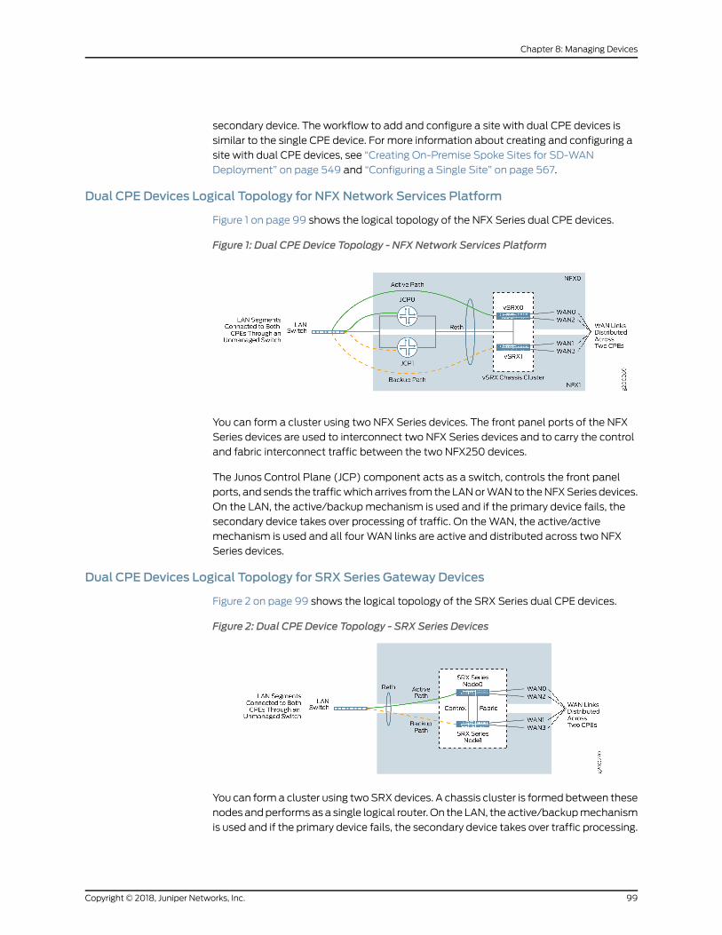
secondary device. The workflow to add and configure a site with dual CPE devices is
similar to the single CPE device. For more information about creating and configuring a
site with dual CPE devices, see “Creating On-Premise Spoke Sites for SD-WAN
Deployment” on page 549 and “Configuring a Single Site” on page 567.
Dual CPE Devices Logical Topology for NFX Network Services Platform
Figure 1 on page 99 shows the logical topology of the NFX Series dual CPE devices.
Figure 1: Dual CPE Device Topology - NFX Network Services Platform
You can form a cluster using two NFX Series devices. The front panel ports of the NFX
Series devices are used to interconnect two NFX Series devices and to carry the control
and fabric interconnect traffic between the two NFX250 devices.
The Junos Control Plane (JCP) component acts as a switch, controls the front panel
ports, and sends the trafficwhich arrives from the LANorWAN to theNFXSeries devices.
On the LAN, the active/backupmechanism is used and if the primary device fails, the
secondary device takes over processing of traffic. On theWAN, the active/active
mechanism is used and all four WAN links are active and distributed across two NFX
Series devices.
Dual CPE Devices Logical Topology for SRX Series Gateway Devices
Figure 2 on page 99 shows the logical topology of the SRX Series dual CPE devices.
Figure 2: Dual CPE Device Topology - SRX Series Devices
You can forma cluster using twoSRXdevices. A chassis cluster is formed between these
nodes andperformsas a single logical router. On the LAN, the active/backupmechanism
is used and if the primary device fails, the secondary device takes over traffic processing.
99Copyright © 2018, Juniper Networks, Inc.
Chapter 8: Managing Devices
On theWAN, the active/active mechanism is used and all four WAN links are active and
distributed across two NFX Series device.
RelatedDocumentation
Creating On-Premise Spoke Sites for SD-WAN Deployment on page 549•
• Configuring a Single Site on page 567
• Activating Dual CPE Devices (Device Redundancy) on page 576
Viewing the History of Tenant Device Activation Logs
You can use the Activation Logs page to view the history of device activation logs. You
can also view the details of the activation logs and their status.
To view the device activation logs:
1. Click Resources > Tenant Devices.
The Tenant Devices page appears, which list all devices.
2. Select a device and clickMore > Activation Logs.
The Activation Logs page is displayed. Table 48 on page 100 describes the fields on
the Activation Logs page.
3. Click a task name.
The ZTP Logs page appears. Table 49 on page 101 describes the fields on the ZTP
Logs page.
4. Click the Task Name.
The Job Status page appears. Table 50 on page 101 describes the fields on the Job
Status page.
5. ClickOK to return to the previous page.
Table 48: Fields on the ZTP History Page
DescriptionField
View the number of activated tasks that are in progress.In progress
View the number of activated tasks that are successful.Success
View the number of activated tasks that have failed.Failure
View the name of the task.
Example:csp.tssm_ztp-Juniper-site-17-NFX-250-8052cc9451914be28c7c98fb64fd0db3
Name
Copyright © 2018, Juniper Networks, Inc.100
Contrail Service Orchestration User Guide
Table 48: Fields on the ZTP History Page (continued)
DescriptionField
View the start date and time of the task.Start Date
View the end date and time of the task.End Date
View the status of the task to knowwhether the task succeeded or failed.Status
View the import logs. Click a log to access more detailed information aboutthe imported log.
Log
Table 49: Fields on the ZTP Logs Page
DescriptionField
View the ID created for the task.
Example: install-license-to-device
Task Name
View the status of the task to knowwhether the task succeeded or failed.Status
Table 50: Fields on the Job Status Page
DescriptionField
View the name of the task.Name
View the start date and time of the task.Actual Start Time
View the name of the user who activated the task.User
View the end date and time of the task.End Time
View the status of the task to knowwhether the task succeeded or failed.State
RelatedDocumentation
About the Tenant Devices Page on page 91•
101Copyright © 2018, Juniper Networks, Inc.
Chapter 8: Managing Devices
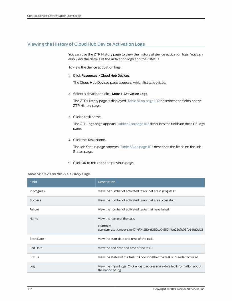
Viewing the History of Cloud Hub Device Activation Logs
You can use the ZTP History page to view the history of device activation logs. You can
also view the details of the activation logs and their status.
To view the device activation logs:
1. Click Resources > Cloud Hub Devices.
The Cloud Hub Devices page appears, which list all devices.
2. Select a device and clickMore > Activation Logs.
The ZTP History page is displayed. Table 51 on page 102 describes the fields on the
ZTP History page.
3. Click a task name.
TheZTPLogspageappears. Table52onpage 103describes the fieldson theZTPLogs
page.
4. Click the Task Name.
The Job Status page appears. Table 53 on page 103 describes the fields on the Job
Status page.
5. ClickOK to return to the previous page.
Table 51: Fields on the ZTP History Page
DescriptionField
View the number of activated tasks that are in progress.In progress
View the number of activated tasks that are successful.Success
View the number of activated tasks that have failed.Failure
View the name of the task.
Example:csp.tssm_ztp-Juniper-site-17-NFX-250-8052cc9451914be28c7c98fb64fd0db3
Name
View the start date and time of the task.Start Date
View the end date and time of the task.End Date
View the status of the task to knowwhether the task succeeded or failed.Status
View the import logs. Click a log to access more detailed information aboutthe imported log.
Log
Copyright © 2018, Juniper Networks, Inc.102
Contrail Service Orchestration User Guide
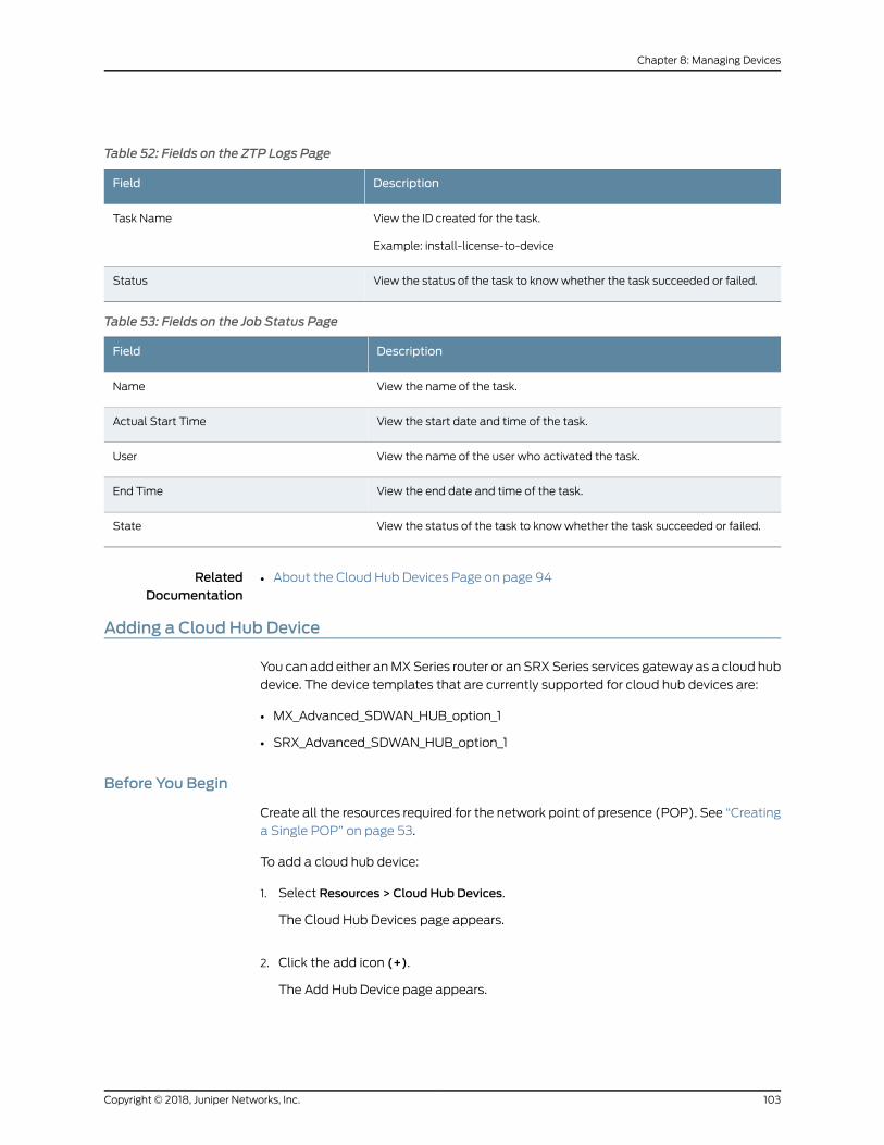
Table 52: Fields on the ZTP Logs Page
DescriptionField
View the ID created for the task.
Example: install-license-to-device
Task Name
View the status of the task to knowwhether the task succeeded or failed.Status
Table 53: Fields on the Job Status Page
DescriptionField
View the name of the task.Name
View the start date and time of the task.Actual Start Time
View the name of the user who activated the task.User
View the end date and time of the task.End Time
View the status of the task to knowwhether the task succeeded or failed.State
RelatedDocumentation
About the Cloud Hub Devices Page on page 94•
Adding a Cloud Hub Device
You can add either anMXSeries router or an SRXSeries services gateway as a cloud hub
device. The device templates that are currently supported for cloud hub devices are:
• MX_Advanced_SDWAN_HUB_option_1
• SRX_Advanced_SDWAN_HUB_option_1
Before You Begin
Create all the resources required for the network point of presence (POP). See “Creating
a Single POP” on page 53.
To add a cloud hub device:
1. Select Resources > Cloud Hub Devices.
The Cloud Hub Devices page appears.
2. Click the add icon (+).
The Add Hub Device page appears.
103Copyright © 2018, Juniper Networks, Inc.
Chapter 8: Managing Devices
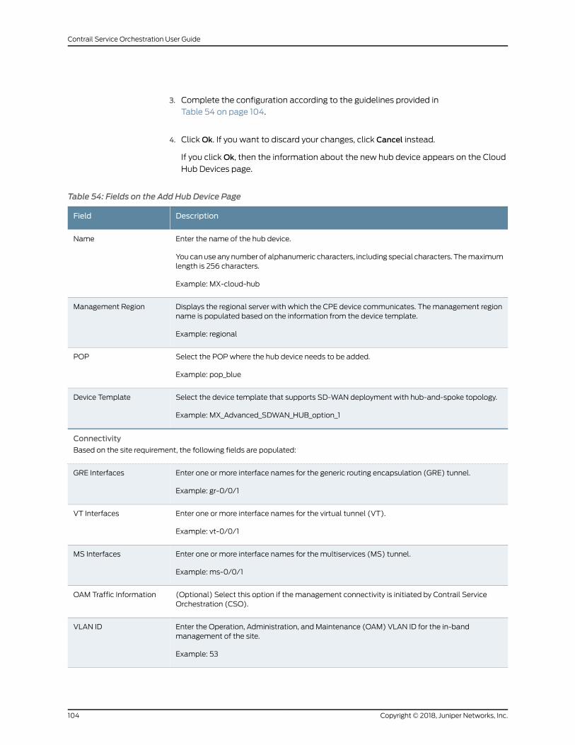
3. Complete the configuration according to the guidelines provided in
Table 54 on page 104.
4. ClickOk. If you want to discard your changes, click Cancel instead.
If you clickOk, then the information about the new hub device appears on the Cloud
Hub Devices page.
Table 54: Fields on the Add Hub Device Page
DescriptionField
Enter the name of the hub device.
You canuse any number of alphanumeric characters, including special characters. Themaximumlength is 256 characters.
Example: MX-cloud-hub
Name
Displays the regional server with which the CPE device communicates. Themanagement regionname is populated based on the information from the device template.
Example: regional
Management Region
Select the POPwhere the hub device needs to be added.
Example: pop_blue
POP
Select the device template that supports SD-WAN deployment with hub-and-spoke topology.
Example: MX_Advanced_SDWAN_HUB_option_1
Device Template
Connectivity
Based on the site requirement, the following fields are populated:
Enter one or more interface names for the generic routing encapsulation (GRE) tunnel.
Example: gr-0/0/1
GRE Interfaces
Enter one or more interface names for the virtual tunnel (VT).
Example: vt-0/0/1
VT Interfaces
Enter one or more interface names for the multiservices (MS) tunnel.
Example: ms-0/0/1
MS Interfaces
(Optional) Select this option if the management connectivity is initiated by Contrail ServiceOrchestration (CSO).
OAM Traffic Information
Enter the Operation, Administration, and Maintenance (OAM) VLAN ID for the in-bandmanagement of the site.
Example: 53
VLAN ID
Copyright © 2018, Juniper Networks, Inc.104
Contrail Service Orchestration User Guide
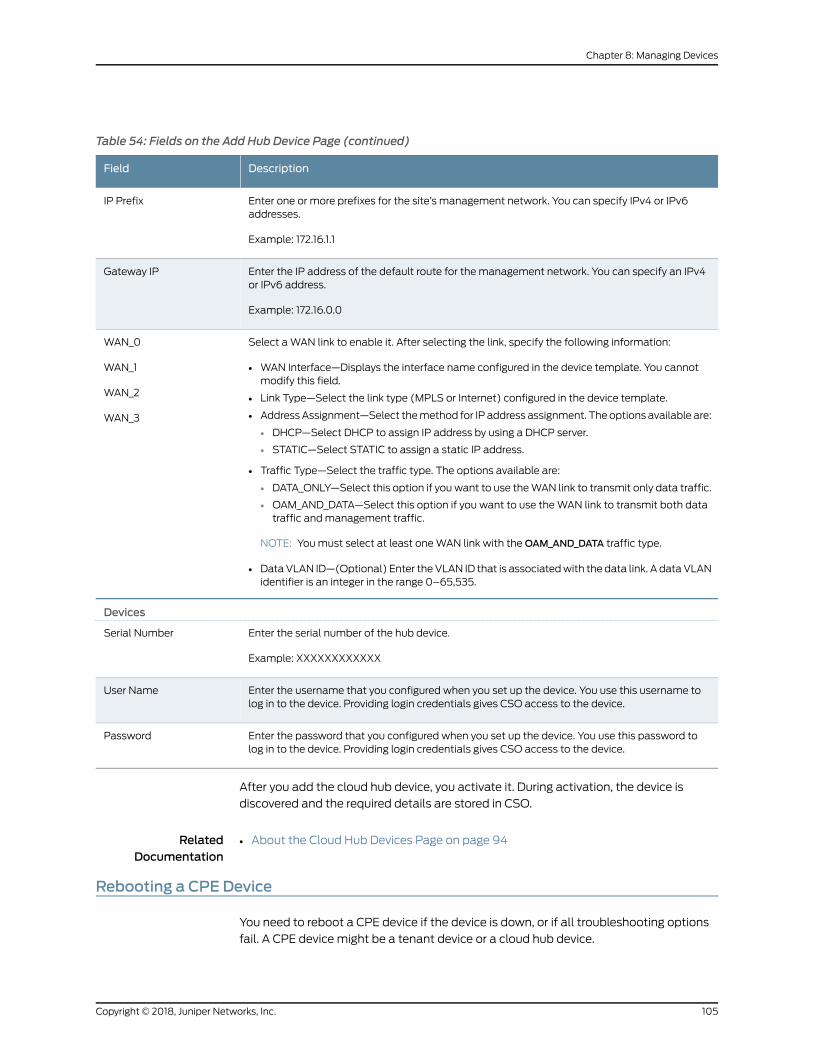
Table 54: Fields on the Add Hub Device Page (continued)
DescriptionField
Enter one or more prefixes for the site’s management network. You can specify IPv4 or IPv6addresses.
Example: 172.16.1.1
IP Prefix
Enter the IP address of the default route for the management network. You can specify an IPv4or IPv6 address.
Example: 172.16.0.0
Gateway IP
Select aWAN link to enable it. After selecting the link, specify the following information:
• WAN Interface—Displays the interface name configured in the device template. You cannotmodify this field.
• Link Type—Select the link type (MPLS or Internet) configured in the device template.
• AddressAssignment—Select themethod for IP address assignment. The options available are:
• DHCP—Select DHCP to assign IP address by using a DHCP server.
• STATIC—Select STATIC to assign a static IP address.
• Traffic Type—Select the traffic type. The options available are:
• DATA_ONLY—Select this option if youwant to use theWAN link to transmit only data traffic.
• OAM_AND_DATA—Select this option if you want to use theWAN link to transmit both datatraffic andmanagement traffic.
NOTE: Youmust select at least oneWAN link with theOAM_AND_DATA traffic type.
• DataVLAN ID—(Optional) Enter theVLAN ID that is associatedwith the data link. A dataVLANidentifier is an integer in the range 0–65,535.
WAN_0
WAN_1
WAN_2
WAN_3
Devices
Enter the serial number of the hub device.
Example: XXXXXXXXXXXX
Serial Number
Enter the username that you configured when you set up the device. You use this username tolog in to the device. Providing login credentials gives CSO access to the device.
User Name
Enter the password that you configured when you set up the device. You use this password tolog in to the device. Providing login credentials gives CSO access to the device.
Password
After you add the cloud hub device, you activate it. During activation, the device is
discovered and the required details are stored in CSO.
RelatedDocumentation
About the Cloud Hub Devices Page on page 94•
Rebooting a CPE Device
You need to reboot a CPE device if the device is down, or if all troubleshooting options
fail. A CPE device might be a tenant device or a cloud hub device.
105Copyright © 2018, Juniper Networks, Inc.
Chapter 8: Managing Devices
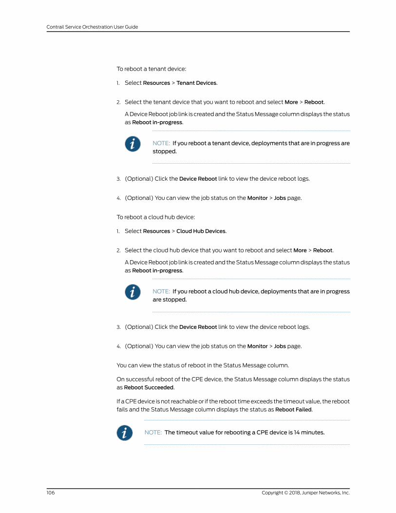
To reboot a tenant device:
1. Select Resources > Tenant Devices.
2. Select the tenant device that you want to reboot and selectMore > Reboot.
ADeviceReboot job link is createdand theStatusMessagecolumndisplays the status
as Reboot in-progress.
NOTE: If you reboot a tenant device, deployments that are in progress arestopped.
3. (Optional) Click the Device Reboot link to view the device reboot logs.
4. (Optional) You can view the job status on theMonitor > Jobs page.
To reboot a cloud hub device:
1. Select Resources > Cloud Hub Devices.
2. Select the cloud hub device that you want to reboot and selectMore > Reboot.
ADeviceReboot job link is createdand theStatusMessagecolumndisplays the status
as Reboot in-progress.
NOTE: If you reboot a cloud hub device, deployments that are in progressare stopped.
3. (Optional) Click the Device Reboot link to view the device reboot logs.
4. (Optional) You can view the job status on theMonitor > Jobs page.
You can view the status of reboot in the Status Message column.
On successful reboot of the CPE device, the Status Message column displays the status
as Reboot Succeeded.
If aCPEdevice isnot reachableor if the reboot timeexceeds the timeout value, the reboot
fails and the Status Message column displays the status as Reboot Failed.
NOTE: The timeout value for rebooting a CPE device is 14minutes.
Copyright © 2018, Juniper Networks, Inc.106
Contrail Service Orchestration User Guide
RelatedDocumentation
• About the Cloud Hub Devices Page on page 94
• About the Tenant Devices Page on page 91
107Copyright © 2018, Juniper Networks, Inc.
Chapter 8: Managing Devices

Copyright © 2018, Juniper Networks, Inc.108
Contrail Service Orchestration User Guide
CHAPTER 9
Managing Device Templates
• About the Device Template Page on page 109
• Cloning a Device Template on page 114
• Importing a Device Template on page 115
• Configuring a Device Template on page 116
• Modifying a Device Template Description on page 123
• Deleting a Device Template on page 124
About the Device Template Page
To access this page, click Resources > Device Templates.
A device template contains configuration and provisioning instructions for a physical
device that youmanage through Contrail Service Orchestration (CSO), such as a CPE
deviceor a router. TheCSO installation includes several device templates forCPEdevices
and other physical devices. The device templates for non-CPE devices are fixed and you
cannot customize them. You assign a device template to this type of device in CSOwhen
you add it to a point of presence (POP). The CPE device templates are specific to the
type of device and topology of the solution. Youmust assign a device template to each
CPE device at each site in a distributed deployment. The CPE device templates contain
three types of information:
• Template settings information prepares the device for remote activation, connects
thedevice to thepeerMXSeries router, and establishes an IPsec tunnelwith the router.
• Stage-2 configuration template information specifies the additional settings that you
or your customercanconfigure for thedevice. Forexample, youcanenableconfiguration
ofaLANand firewall policies. Youcreate theseconfiguration templates inConfiguration
Designer and provide implementation details in the device template.
• Stage-2 initial configuration information provides the actual values for the stage-2
configuration templates. In general, your customers perform this configuration through
Customer Portal.
In some cases, however, youmightwant all CPE devices to use the same values, and you
have the option to provide those values through the device template. You can use the
default CSO CPE device templates if they are suitable for the topology of your solution.
109Copyright © 2018, Juniper Networks, Inc.
Youcanalsocustomize thedefaultdevice templatesor createyourowndevice templates
and upload them to CSO.
The device templates support the following deployment models:
• MPLSWANwith Internet backup—Device templates NFX_deployment_option_1 and
SRX_deployment_option_1 support this deployment model.
• SecureWAN over Internet—Device template NFX_deployment_option_4 supports this
deployment model.
• CPE for a Managed Internet Service—Device templates NFX_Managed_Internet_CPE
and SRX_Managed_Internet_CPE support this deployment model.
Tasks You Can Perform
You can perform the following tasks from this page:
• Clone a device template. See “Cloning a Device Template” on page 114.
• Import a device template from a file. See “Importing a Device Template” on page 115.
• Configure a device template. See “Configuring a Device Template” on page 116.
• Modify a device template description. See “Modifying a Device Template Description”
on page 123.
• Delete a device template. See “Deleting a Device Template” on page 124.
• View details about a device template. See “Viewing Object Details” on page 14.
• Show or hide columns about the templates. See “Sorting Objects” on page 15.
• Searchanobject about the templates. See “Searching for Text in anObjectDataTable”
on page 15.
Field Descriptions
Table 55 on page 111 describes the fields on the Device Templates page.
Copyright © 2018, Juniper Networks, Inc.110
Contrail Service Orchestration User Guide
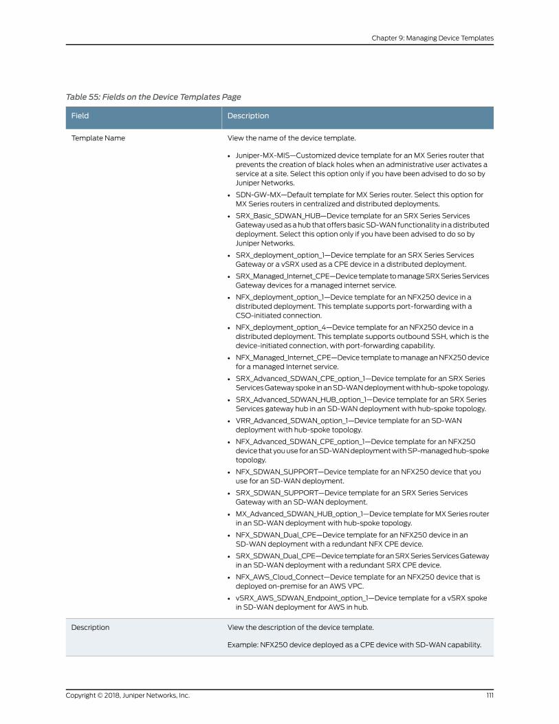
Table 55: Fields on the Device Templates Page
DescriptionField
View the name of the device template.
• Juniper-MX-MIS—Customized device template for an MX Series router thatprevents the creation of black holes when an administrative user activates aservice at a site. Select this option only if you have been advised to do so byJuniper Networks.
• SDN-GW-MX—Default template for MX Series router. Select this option forMX Series routers in centralized and distributed deployments.
• SRX_Basic_SDWAN_HUB—Device template for an SRX Series ServicesGatewayusedasahub thatoffersbasicSD-WANfunctionality inadistributeddeployment. Select this option only if you have been advised to do so byJuniper Networks.
• SRX_deployment_option_1—Device template for an SRX Series ServicesGateway or a vSRX used as a CPE device in a distributed deployment.
• SRX_Managed_Internet_CPE—Device template tomanageSRXSeriesServicesGateway devices for a managed internet service.
• NFX_deployment_option_1—Device template for an NFX250 device in adistributed deployment. This template supports port-forwarding with aCSO-initiated connection.
• NFX_deployment_option_4—Device template for an NFX250 device in adistributed deployment. This template supports outbound SSH, which is thedevice-initiated connection, with port-forwarding capability.
• NFX_Managed_Internet_CPE—Device template tomanageanNFX250devicefor a managed Internet service.
• SRX_Advanced_SDWAN_CPE_option_1—Device template for an SRX SeriesServicesGatewayspoke inanSD-WANdeploymentwithhub-spoke topology.
• SRX_Advanced_SDWAN_HUB_option_1—Device template for an SRX SeriesServices gateway hub in an SD-WAN deployment with hub-spoke topology.
• VRR_Advanced_SDWAN_option_1—Device template for an SD-WANdeployment with hub-spoke topology.
• NFX_Advanced_SDWAN_CPE_option_1—Device template for an NFX250device thatyouuse foranSD-WANdeploymentwithSP-managedhub-spoketopology.
• NFX_SDWAN_SUPPORT—Device template for an NFX250 device that youuse for an SD-WAN deployment.
• SRX_SDWAN_SUPPORT—Device template for an SRX Series ServicesGateway with an SD-WAN deployment.
• MX_Advanced_SDWAN_HUB_option_1—Device template forMXSeries routerin an SD-WAN deployment with hub-spoke topology.
• NFX_SDWAN_Dual_CPE—Device template for an NFX250 device in anSD-WAN deployment with a redundant NFX CPE device.
• SRX_SDWAN_Dual_CPE—Device template foranSRXSeriesServicesGatewayin an SD-WAN deployment with a redundant SRX CPE device.
• NFX_AWS_Cloud_Connect—Device template for an NFX250 device that isdeployed on-premise for an AWS VPC.
• vSRX_AWS_SDWAN_Endpoint_option_1—Device template for a vSRX spokein SD-WAN deployment for AWS in hub.
Template Name
View the description of the device template.
Example: NFX250 device deployed as a CPE device with SD-WAN capability.
Description
111Copyright © 2018, Juniper Networks, Inc.
Chapter 9: Managing Device Templates
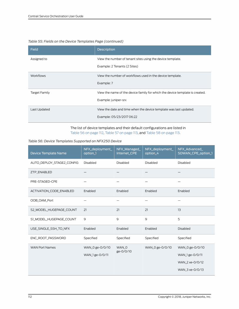
Table 55: Fields on the Device Templates Page (continued)
DescriptionField
View the number of tenant sites using the device template.
Example: 2 Tenants (2 Sites)
Assigned to
View the number of workflows used in the device template.
Example: 7
Workflows
View the name of the device family for which the device template is created.
Example: juniper-srx
Target Family
View the date and time when the device template was last updated.
Example: 05/23/2017 06:22
Last Updated
The list of device templates and their default configurations are listed in
Table 56 on page 112, Table 57 on page 113, and Table 58 on page 113.
Table 56: Device Templates Supported on NFX250 Device
NFX_Advanced_SDWAN_CPE_option_1
NFX_deployment_option_4
NFX_Managed_Internet_CPE
NFX_deployment_option_1Device Template Name
DisabledDisabledDisabledDisabledAUTO_DEPLOY_STAGE2_CONFIG
————ZTP_ENABLED
————PRE-STAGED-CPE
EnabledEnabledEnabledEnabledACTIVATION_CODE_ENABLED
————OOB_OAM_Port
13212121S2_MODEL_HUGEPAGE_COUNT
5999S1_MODEL_HUGEPAGE_COUNT
DisabledEnabledEnabledEnabledUSE_SINGLE_SSH_TO_NFX
SpecifiedSpecifiedSpecifiedSpecifiedENC_ROOT_PASSWORD
WAN_0 ge-0/0/10
WAN_1 ge-0/0/11
WAN_2 xe-0/0/12
WAN_3 xe-0/0/13
WAN_0 ge-0/0/10WAN_0ge-0/0/10
WAN_0 ge-0/0/10
WAN_1 ge-0/0/11
WAN Port Names
Copyright © 2018, Juniper Networks, Inc.112
Contrail Service Orchestration User Guide
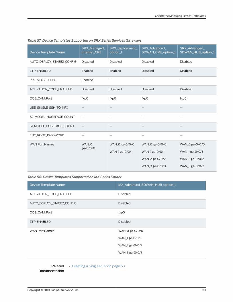
Table 57: Device Templates Supported on SRX Series Services Gateways
SRX_Advanced_SDWAN_HUB_option_1
SRX_Advanced_SDWAN_CPE_option_1
SRX_deployment_option_1
SRX_Managed_Internet_CPEDevice Template Name
DisabledDisabledDisabledDisabledAUTO_DEPLOY_STAGE2_CONFIG
DisabledDisabledEnabledEnabledZTP_ENABLED
———EnabledPRE-STAGED-CPE
DisabledDisabledDisabledDisabledACTIVATION_CODE_ENABLED
fxp0fxp0fxp0fxp0OOB_OAM_Port
————USE_SINGLE_SSH_TO_NFX
————S2_MODEL_HUGEPAGE_COUNT
————S1_MODEL_HUGEPAGE_COUNT
————ENC_ROOT_PASSWORD
WAN_0 ge-0/0/0
WAN_1 ge-0/0/1
WAN_2 ge-0/0/2
WAN_3 ge-0/0/3
WAN_0 ge-0/0/0
WAN_1 ge-0/0/1
WAN_2 ge-0/0/2
WAN_3 ge-0/0/3
WAN_0 ge-0/0/0
WAN_1 ge-0/0/1
WAN_0ge-0/0/0
WAN Port Names
Table 58: Device Templates Supported onMX Series Router
MX_Advanced_SDWAN_HUB_option_1Device Template Name
DisabledACTIVATION_CODE_ENABLED
DisabledAUTO_DEPLOY_STAGE2_CONFIG
fxp0OOB_OAM_Port
DisabledZTP_ENABLED
WAN_0 ge-0/0/0
WAN_1 ge-0/0/1
WAN_2 ge-0/0/2
WAN_3 ge-0/0/3
WAN Port Names
RelatedDocumentation
Creating a Single POP on page 53•
113Copyright © 2018, Juniper Networks, Inc.
Chapter 9: Managing Device Templates
• Creating Devices on page 83
Cloning a Device Template
Cloning a device template is useful when you want to create a device template that is
similar to an existing one but with small differences. You can clone a device template by
using either of the methodsmentioned below:
To clone a device template:
1. Select Resources > Device Templates.
The Device Template page appears.
2. Select the device template that you want to clone, and click Clone.
The Clone Template page appears.
3. Specify an appropriate name for your new device template. For example,
SRX_Advanced_SDWAN_CPE_option_1_Custom.
4. ClickOk.
The cloned device template appears on the Device Template page. You can now edit
the new device template and customize the configurations as needed.
You can also clone the device template by performing the following procedure:
1. Select Resources > Device Templates.
The Device Template page appears.
2. Select the device template that you want to clone, and then select Edit Device
Template > Template Settings.
The Template Settings page appears.
3. Modify the configurations as required and click Save As.
The Create Device template page appears.
4. Specify an appropriate name for your new device template. For example,
SRX_Advanced_SDWAN_CPE_option_1_Custom.
5. ClickOk.
The cloned device template appears on the Device Template page. You can now edit
the new device template and customize the configurations as needed.
Copyright © 2018, Juniper Networks, Inc.114
Contrail Service Orchestration User Guide
RelatedDocumentation
Importing a Device Template on page 115•
Importing a Device Template
Use the Resources > Device Templates page to import a device template in JSON format
for the customer.
NOTE: Youmust create adevice template file before you can import a devicetemplate
• Creating a Device Template File on page 115
• Importing a Device Template File on page 115
Creating a Device Template File
To create a file of device information:
1. Select Resources > Device Templates > Import Device Template.
The Import Device Template page appears.
2. Click the Download Sample JSON link to open and save the sample JSON data file.
The sample file opens at the bottom of the page.
3. Save the template file with an appropriate name to your computer.
NOTE: Youmust retain the file format as .json to successfully upload thedevice template details to the Administration Portal.
4. Customize the sample JSON file according to the deployment.
5. Save the customized file.
Importing a Device Template File
Device templates are used to configure cloud CPE devices on a tenant site and these
templates must be assigned to the device before you activate the device.
NOTE: A device template data file is required before your import devicetemplates.
115Copyright © 2018, Juniper Networks, Inc.
Chapter 9: Managing Device Templates
To import device template configuration:
1. Select Resources > Device Templates > Import Device Template.
The Import Device Template page appears.
2. ClickBrowseandnavigate to thedirectory containing thedevice templateconfiguration
JSON file.
3. Select the file and clickOpen.
4. Click Import Device Templates. If you want to discard the import process, click Cancel
instead.
The Device Templates Import Completed page appears with the details of the
successful import.
5. ClickOK to complete the import process.
The imported device template is displayed on the Device Template page.
RelatedDocumentation
Creating a Single POP on page 53•
Configuring a Device Template
Device templates contain global parameters and workflows. Global parameters are a
set of variables that can be customized easily.
• Configuring Template Settings in a Device Template on page 116
• Updating Stage-2 Configuration Template in a Device Template on page 119
• Configuring Stage-2 Initial Configuration on page 122
Configuring Template Settings in a Device Template
To configure the device template settings:
1. Select Resources > Device Template.
The Device Templates page appears.
2. Select a device template for which youwant to configure the settings and then select
Edit Device Template > Template Settings.
The Template Settings page appears.
Copyright © 2018, Juniper Networks, Inc.116
Contrail Service Orchestration User Guide
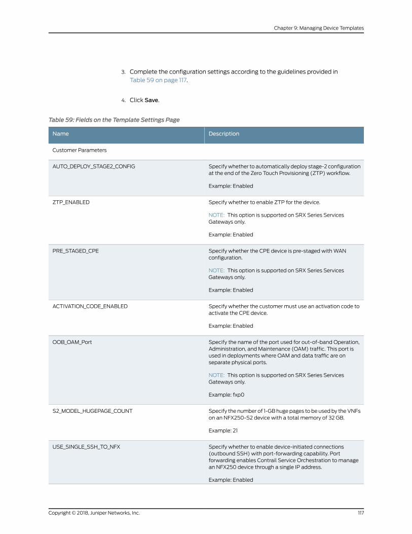
3. Complete the configuration settings according to the guidelines provided in
Table 59 on page 117.
4. Click Save.
Table 59: Fields on the Template Settings Page
DescriptionName
Customer Parameters
Specifywhether to automatically deploy stage-2 configurationat the end of the Zero Touch Provisioning (ZTP) workflow.
Example: Enabled
AUTO_DEPLOY_STAGE2_CONFIG
Specify whether to enable ZTP for the device.
NOTE: This option is supported on SRX Series ServicesGateways only.
Example: Enabled
ZTP_ENABLED
Specify whether the CPE device is pre-staged withWANconfiguration.
NOTE: This option is supported on SRX Series ServicesGateways only.
Example: Enabled
PRE_STAGED_CPE
Specify whether the customer must use an activation code toactivate the CPE device.
Example: Enabled
ACTIVATION_CODE_ENABLED
Specify the name of the port used for out-of-band Operation,Administration, and Maintenance (OAM) traffic. This port isused in deployments where OAM and data traffic are onseparate physical ports.
NOTE: This option is supported on SRX Series ServicesGateways only.
Example: fxp0
OOB_OAM_Port
Specify the number of 1-GBhuge pages to be used by theVNFson an NFX250-S2 device with a total memory of 32 GB.
Example: 21
S2_MODEL_HUGEPAGE_COUNT
Specify whether to enable device-initiated connections(outbound SSH) with port-forwarding capability. Portforwarding enables Contrail Service Orchestration to managean NFX250 device through a single IP address.
Example: Enabled
USE_SINGLE_SSH_TO_NFX
117Copyright © 2018, Juniper Networks, Inc.
Chapter 9: Managing Device Templates
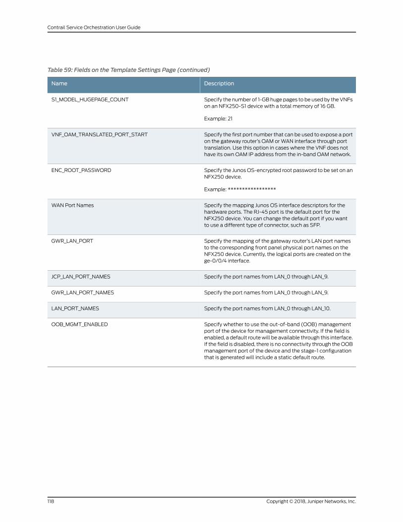
Table 59: Fields on the Template Settings Page (continued)
DescriptionName
Specify the number of 1-GBhuge pages to be used by theVNFson an NFX250-S1 device with a total memory of 16 GB.
Example: 21
S1_MODEL_HUGEPAGE_COUNT
Specify the first port number that can be used to expose a porton the gateway router’s OAM orWAN interface through porttranslation. Use this option in cases where the VNF does nothave its own OAM IP address from the in-band OAM network.
VNF_OAM_TRANSLATED_PORT_START
Specify the JunosOS-encrypted root password to be set on anNFX250 device.
Example: *****************
ENC_ROOT_PASSWORD
Specify the mapping Junos OS interface descriptors for thehardware ports. The RJ-45 port is the default port for theNFX250 device. You can change the default port if you wantto use a different type of connector, such as SFP.
WAN Port Names
Specify the mapping of the gateway router’s LAN port namesto the corresponding front panel physical port names on theNFX250 device. Currently, the logical ports are created on thege-0/0/4 interface.
GWR_LAN_PORT
Specify the port names from LAN_0 through LAN_9.JCP_LAN_PORT_NAMES
Specify the port names from LAN_0 through LAN_9.GWR_LAN_PORT_NAMES
Specify the port names from LAN_0 through LAN_10.LAN_PORT_NAMES
Specify whether to use the out-of-band (OOB)managementport of the device for management connectivity. If the field isenabled, a default routewill be available through this interface.If the field is disabled, there is no connectivity through theOOBmanagement port of the device and the stage-1 configurationthat is generated will include a static default route.
OOB_MGMT_ENABLED
Copyright © 2018, Juniper Networks, Inc.118
Contrail Service Orchestration User Guide
Updating Stage-2 Configuration Template in a Device Template
Each device template has a set of configuration templates that can be used to deploy
additional configuration on to the CPE device after it is activated. These templates are
known as stage-2 configuration templates. You can add or remove stage-2 configuration
templates from a device template.
NOTE: By default, the CPE device configuration is not supported on the CPEdevice. If you need the CPE device configuration, then youmust configure itthrough stage-2 configuration in the device templates.
To add a stage-2 configuration template:
1. Select Resources > Device Template.
The Device Templates page appears.
2. Select a device template for which you want to add the stage-2 configuration and
select Edit Device Template > Stage-2 Config Templates.
The Stage-2 Configuration Templates page appears. Table 60 on page 119 lists the
fields (and their descriptions) on the Stage-2 Configuration Templates page.
3. Click the add icon (+) and complete the configuration settings according to the
guidelines provided in Table 61 on page 120.
4. Click Save.
The new stage-2 configuration template is included in the device template.
Table 60: Fields on the Stage-2 Configuration Templates Page
DescriptionName
View the name of the stage-2 configuration template.
Example: LAN side config
Name
View the name of the device family.
Example: juniper-srx
Family
119Copyright © 2018, Juniper Networks, Inc.
Chapter 9: Managing Device Templates
Table 60: Fields on the Stage-2 Configuration Templates Page (continued)
DescriptionName
Viewthenameof thecomponent throughwhich thesettingsareconfigured.Thecomponentsthat are currently supported are:
• JUNOS—Supported on SRX Series Services Gateway.
• Juniper Device Manager (JDM)—Supported on NFX250 device. JDM is a Linux containerthat manages software components.
• Juniper Control Plane (JCP)—Supported on NFX250 device. JCP is the Junos VM runningon thehypervisor. Administrators canuse JCP toconfigure thenetworkportsof theNFX250device. JCP is used to configure the switching and routing function on the NFX250 device.
• Gateway Router (GWR)—Supported on NFX250 device. vSRX as a gateway provides thesame capabilities as Juniper Networks SRX Series Services Gateways in a virtual formfactor, providing perimeter security, IPsec connectivity, and filtering for malicious trafficwithout sacrificing reliability, visibility, or policy control. This virtual security and routingappliance ensures reliability and high availability for each application.
Example: JUNOS
Component Name
Displays whether the template is hidden on Customer Portal.
• true—Template is not visible on Customer Portal.
• false—Template is visible on Customer Portal.
Example: false
Hide
Table 61: Fields on the Add New Template Page
DescriptionName
Select the configuration template from the drop-down list. The configuration templates aredesigned in the Configuration Designer tool.
Example: srx-basic-sdwan-cpe-config
Template
Specify the name of the template that you want to display on the configuration interface.
Example: SDWAN Config
Display Name
Specify the component name through which the settings are configured. The componentsthat are currently supported are:
• JUNOS—Supported on SRX Series Services Gateway.
• Juniper Device Manager (JDM)— Supported on NFX250 device. JDM is a Linux containerthat manages software components.
• Juniper Control Plane (JCP)—Supported on NFX250 device. JCP is the Junos VM runningon thehypervisor. Administrators canuse JCP toconfigure thenetworkportsof theNFX250device. JCP is used to configure the switching and routing function on the NFX250 device.
• Gateway Router (GWR)—Supported on NFX250 device. vSRX as a gateway provides thesame capabilities as Juniper Networks SRX Series Services Gateways in a virtual formfactor, providing perimeter security, IPsec connectivity, and filtering for malicious trafficwithout sacrificing reliability, visibility, or policy control. This virtual security and routingappliance ensures reliability and high availability for each application.
Example: JUNOS
Component Name
Copyright © 2018, Juniper Networks, Inc.120
Contrail Service Orchestration User Guide
Table 61: Fields on the Add New Template Page (continued)
DescriptionName
Specifywhether youwant to hide the configuration template onCustomer Portal. Youmightwant tochoose tohide the template if youare reusing the template formultiple components.
• hide—White dot on right with blue background.
• show—White dot on left with gray background.
Example: hide
Hide
If you have chosen to hide the configuration template on the user interface, then specify thetemplate fromwhich you want to copy the settings.
Example: srx-mis-lan-to-wan-config
Copy From Template
To remove a stage-2 configuration template:
1. Select Resources > Device Templates.
The Device Templates page appears.
2. Select the device template for which you want to remove the stage-2 configuration
and then select Edit Device Template > Stage-2 Config Templates.
The Stage-2 Config Templates page appears.
3. Select a configuration template and click the delete icon (X).
A page requesting confirmation for the deletion appears.
4. Click Yes to confirm that you want to delete the stage-2 configuration template.
The configuration template is deleted.
121Copyright © 2018, Juniper Networks, Inc.
Chapter 9: Managing Device Templates
Configuring Stage-2 Initial Configuration
In general, the tenant administrators initiate stage-2 configuration through Customer
Portal. However, in certain cases, the same stage-2 configuration needs to be deployed
to CPE devices in all sites that are activated using a specific device template. In such
cases, you can attach an initial configuration to a stage-2 config template of a device
template. When a new CPE device in the site is activated using the device template, the
initial configuration is automatically deployed to the CPE device.
The list of initial configurations that are supported are:
• Policies configuration
• LAN configuration
• SD-WAN configuration
• Routing configuration
To update an initial configuration for stage-2 configuration template:
1. Select Resources > Device Templates.
The Device Templates page appears.
2. Select the device template for which you want to configure the stage-2 configuration
and then select Edit Device Template > Stage-2 Initial Config.
The Stage-2 Initial Configuration page appears, listing the existing settings.
3. Complete the configuration settings according to the guidelines provided in
Table 62 on page 122, Table 63 on page 123, and Table 64 on page 123.
4. ClickOk.
Table 62: Fields for the VLAN Settings on the Stage-2 Initial Configuration Page
DescriptionField
Specify the identifier for the Layer 2 VLAN for the CPE device.
Example: 230
VLAN ID
Specify the IP address, including the subnet prefix, and the integrated routingand bridging (IRB) interface on the CPE device.
Example: 192.0.2.15/24
IRB IP Prefix
Specify the LAN ports on the CPE device.
Example: ge-0/0/0
LAN Ports
Copyright © 2018, Juniper Networks, Inc.122
Contrail Service Orchestration User Guide
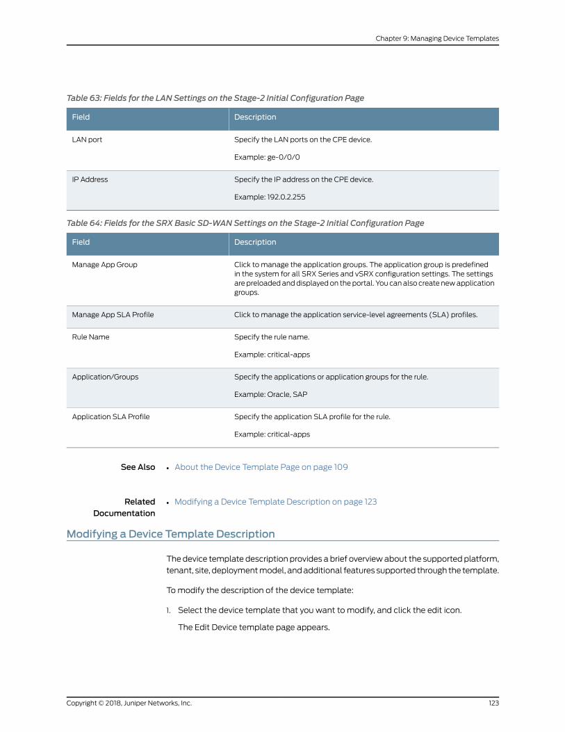
Table 63: Fields for the LAN Settings on the Stage-2 Initial Configuration Page
DescriptionField
Specify the LAN ports on the CPE device.
Example: ge-0/0/0
LAN port
Specify the IP address on the CPE device.
Example: 192.0.2.255
IP Address
Table 64: Fields for the SRX Basic SD-WAN Settings on the Stage-2 Initial Configuration Page
DescriptionField
Click to manage the application groups. The application group is predefinedin the system for all SRX Series and vSRX configuration settings. The settingsarepreloadedanddisplayedon theportal. You canalso create newapplicationgroups.
Manage App Group
Click to manage the application service-level agreements (SLA) profiles.Manage App SLA Profile
Specify the rule name.
Example: critical-apps
Rule Name
Specify the applications or application groups for the rule.
Example: Oracle, SAP
Application/Groups
Specify the application SLA profile for the rule.
Example: critical-apps
Application SLA Profile
See Also About the Device Template Page on page 109•
RelatedDocumentation
Modifying a Device Template Description on page 123•
Modifying a Device Template Description
Thedevice template description provides a brief overviewabout the supported platform,
tenant, site, deploymentmodel, andadditional features supported through the template.
Tomodify the description of the device template:
1. Select the device template that you want to modify, and click the edit icon.
The Edit Device template page appears.
123Copyright © 2018, Juniper Networks, Inc.
Chapter 9: Managing Device Templates
2. Enterameaningfuldescription for thedevice template. Forexample:NFX250deployed
as a CPE device with SD-WAN capability.
3. ClickOk to save the changes.
The description that you updated is listed in the device template table.
RelatedDocumentation
About the Device Template Page on page 109•
Deleting a Device Template
Before deleting a device template, ensure that the template is not associated with any
tenant site or a CPE device.
To delete a device template file:
1. Select Resources > Device Templates.
The Device Template page appears.
2. Select the device template that you want to delete and click Delete.
A page requesting confirmation for the deletion appears.
3. Click Yes to confirm that you want to delete the device template.
The device template is deleted.
RelatedDocumentation
• About the Device Template Page on page 109
Copyright © 2018, Juniper Networks, Inc.124
Contrail Service Orchestration User Guide
CHAPTER 10
Managing Software Images
• Device Images Overview on page 125
• About the Device Images Page on page 126
• Deploying Device Images to Devices on page 127
• Uploading a Device Image on page 129
• Deleting Device Images on page 131
Device Images Overview
An imagemanagement system provides full lifecycle management of images for all
network devices, including CPE device and virtualized network function (VNF) images.
A device image is a software installation package for the CPE device or an image for a
virtual application that runs on the device. For example, for aNFXSeries device platform,
you require an NFX software image and a software image for the vSRX application that
provides security functions and routing on the device. You install a VNF image on a CPE
device or on a server in a service provider’s cloud to deploy the VNF in that location.
Administration Portal enables you to upload both CPE device and VNF images from your
local file systemanddeploy themonasingledeviceor simultaneouslyonmultipledevices
of the same family. CPE device images include software images for the NFX Series, MX
Series, and SRX Series. You can download software images from Junos Platforms -
Download Software.
After you upload a CPE device or VNF image, you can stage the image on a device, verify
the checksum, and deploy the staged image using the Deploy option from the Images
page. You can also schedule the staging, deployment, and validation of a device image.
In addition, you canmodify the platforms supported by the device image and the
description of the device image.
Youcanstoreall the images in a central repository andusea file service to retrieve images
from the file server when the image needs to be deployed to the devices.
RelatedDocumentation
About the Device Images Page on page 126•
125Copyright © 2018, Juniper Networks, Inc.
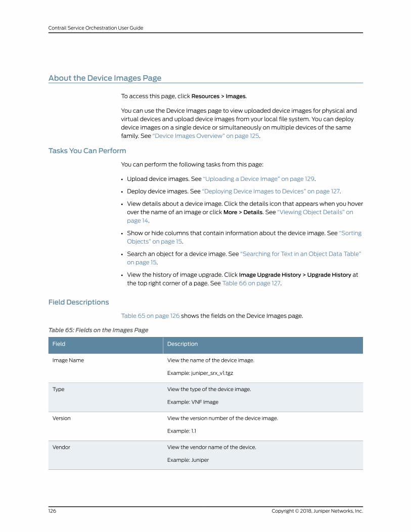
About the Device Images Page
To access this page, click Resources > Images.
You can use the Device Images page to view uploaded device images for physical and
virtual devices and upload device images from your local file system. You can deploy
device images on a single device or simultaneously onmultiple devices of the same
family. See “Device Images Overview” on page 125.
Tasks You Can Perform
You can perform the following tasks from this page:
• Upload device images. See “Uploading a Device Image” on page 129.
• Deploy device images. See “Deploying Device Images to Devices” on page 127.
• View details about a device image. Click the details icon that appears when you hover
over the name of an image or clickMore > Details. See “Viewing Object Details” on
page 14.
• Show or hide columns that contain information about the device image. See “Sorting
Objects” on page 15.
• Search an object for a device image. See “Searching for Text in an Object Data Table”
on page 15.
• View the history of image upgrade. Click Image Upgrade History > Upgrade History at
the top right corner of a page. See Table 66 on page 127.
Field Descriptions
Table 65 on page 126 shows the fields on the Device Images page.
Table 65: Fields on the Images Page
DescriptionField
View the name of the device image.
Example: juniper_srx_v1.tgz
Image Name
View the type of the device image.
Example: VNF Image
Type
View the version number of the device image.
Example: 1.1
Version
View the vendor name of the device.
Example: Juniper
Vendor
Copyright © 2018, Juniper Networks, Inc.126
Contrail Service Orchestration User Guide
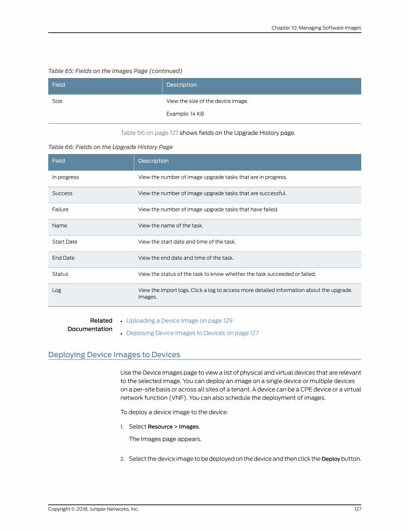
Table 65: Fields on the Images Page (continued)
DescriptionField
View the size of the device image.
Example: 14 KB
Size
Table 66 on page 127 shows fields on the Upgrade History page.
Table 66: Fields on the Upgrade History Page
DescriptionField
View the number of image upgrade tasks that are in progress.In progress
View the number of image upgrade tasks that are successful.Success
View the number of image upgrade tasks that have failed.Failure
View the name of the task.Name
View the start date and time of the task.Start Date
View the end date and time of the task.End Date
View the status of the task to knowwhether the task succeeded or failed.Status
View the import logs. Click a log to access more detailed information about the upgradeimages.
Log
RelatedDocumentation
Uploading a Device Image on page 129•
• Deploying Device Images to Devices on page 127
Deploying Device Images to Devices
Use theDevice Images page to view a list of physical and virtual devices that are relevant
to the selected image. You can deploy an image on a single device or multiple devices
on a per-site basis or across all sites of a tenant. A device can be a CPE device or a virtual
network function (VNF). You can also schedule the deployment of images.
To deploy a device image to the device:
1. Select Resource > Images.
The Images page appears.
2. Select thedevice image tobedeployedon thedeviceand thenclick theDeploybutton.
127Copyright © 2018, Juniper Networks, Inc.
Chapter 10: Managing Software Images
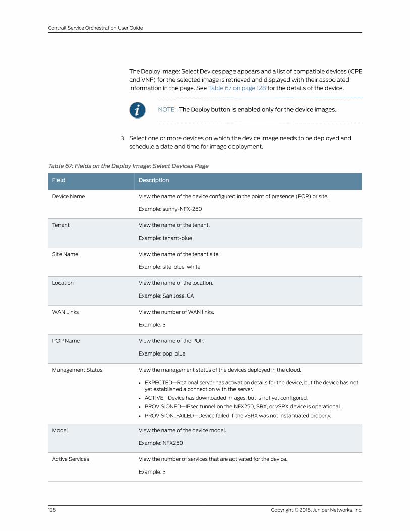
TheDeploy Image: SelectDevices pageappears anda list of compatible devices (CPE
and VNF) for the selected image is retrieved and displayed with their associated
information in the page. See Table 67 on page 128 for the details of the device.
NOTE: The Deploy button is enabled only for the device images.
3. Select one or more devices on which the device image needs to be deployed and
schedule a date and time for image deployment.
Table 67: Fields on the Deploy Image: Select Devices Page
DescriptionField
View the name of the device configured in the point of presence (POP) or site.
Example: sunny-NFX-250
Device Name
View the name of the tenant.
Example: tenant-blue
Tenant
View the name of the tenant site.
Example: site-blue-white
Site Name
View the name of the location.
Example: San Jose, CA
Location
View the number of WAN links.
Example: 3
WAN Links
View the name of the POP.
Example: pop_blue
POP Name
View themanagement status of the devices deployed in the cloud.
• EXPECTED—Regional server has activation details for the device, but the device has notyet established a connection with the server.
• ACTIVE—Device has downloaded images, but is not yet configured.
• PROVISIONED—IPsec tunnel on the NFX250, SRX, or vSRX device is operational.
• PROVISION_FAILED—Device failed if the vSRX was not instantiated properly.
Management Status
View the name of the device model.
Example: NFX250
Model
View the number of services that are activated for the device.
Example: 3
Active Services
Copyright © 2018, Juniper Networks, Inc.128
Contrail Service Orchestration User Guide
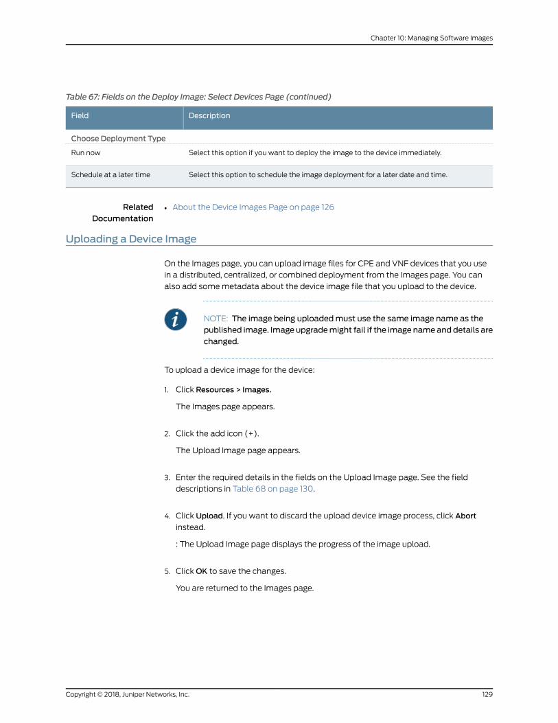
Table 67: Fields on the Deploy Image: Select Devices Page (continued)
DescriptionField
Choose Deployment Type
Select this option if you want to deploy the image to the device immediately.Run now
Select this option to schedule the image deployment for a later date and time.Schedule at a later time
RelatedDocumentation
About the Device Images Page on page 126•
Uploading a Device Image
On the Images page, you can upload image files for CPE and VNF devices that you use
in a distributed, centralized, or combined deployment from the Images page. You can
also add somemetadata about the device image file that you upload to the device.
NOTE: The image being uploadedmust use the same image name as thepublished image. Image upgrademight fail if the image nameanddetails arechanged.
To upload a device image for the device:
1. Click Resources > Images.
The Images page appears.
2. Click the add icon (+).
The Upload Image page appears.
3. Enter the required details in the fields on the Upload Image page. See the field
descriptions in Table 68 on page 130.
4. Click Upload. If you want to discard the upload device image process, click Abort
instead.
: The Upload Image page displays the progress of the image upload.
5. ClickOK to save the changes.
You are returned to the Images page.
129Copyright © 2018, Juniper Networks, Inc.
Chapter 10: Managing Software Images
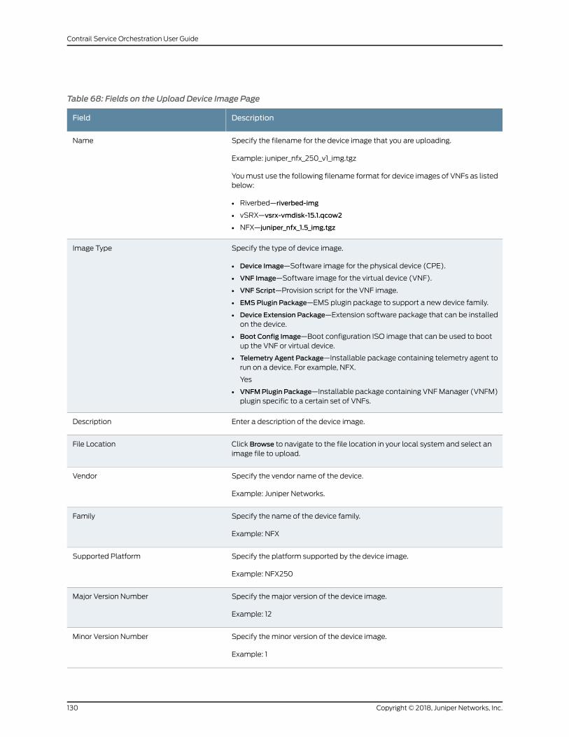
Table 68: Fields on the Upload Device Image Page
DescriptionField
Specify the filename for the device image that you are uploading.
Example: juniper_nfx_250_v1_img.tgz
Youmust use the following filename format for device images of VNFs as listedbelow:
• Riverbed—riverbed-img
• vSRX—vsrx-vmdisk-15.1.qcow2
• NFX—juniper_nfx_1.5_img.tgz
Name
Specify the type of device image.
• Device Image—Software image for the physical device (CPE).
• VNF Image—Software image for the virtual device (VNF).
• VNF Script—Provision script for the VNF image.
• EMS Plugin Package—EMS plugin package to support a new device family.
• Device Extension Package—Extension software package that can be installedon the device.
• Boot Config Image—Boot configuration ISO image that can be used to bootup the VNF or virtual device.
• Telemetry Agent Package—Installable package containing telemetry agent torun on a device. For example, NFX.
Yes
• VNFMPlugin Package—Installable package containing VNFManager (VNFM)plugin specific to a certain set of VNFs.
Image Type
Enter a description of the device image.Description
Click Browse to navigate to the file location in your local system and select animage file to upload.
File Location
Specify the vendor name of the device.
Example: Juniper Networks.
Vendor
Specify the name of the device family.
Example: NFX
Family
Specify the platform supported by the device image.
Example: NFX250
Supported Platform
Specify the major version of the device image.
Example: 12
Major Version Number
Specify the minor version of the device image.
Example: 1
Minor Version Number
Copyright © 2018, Juniper Networks, Inc.130
Contrail Service Orchestration User Guide
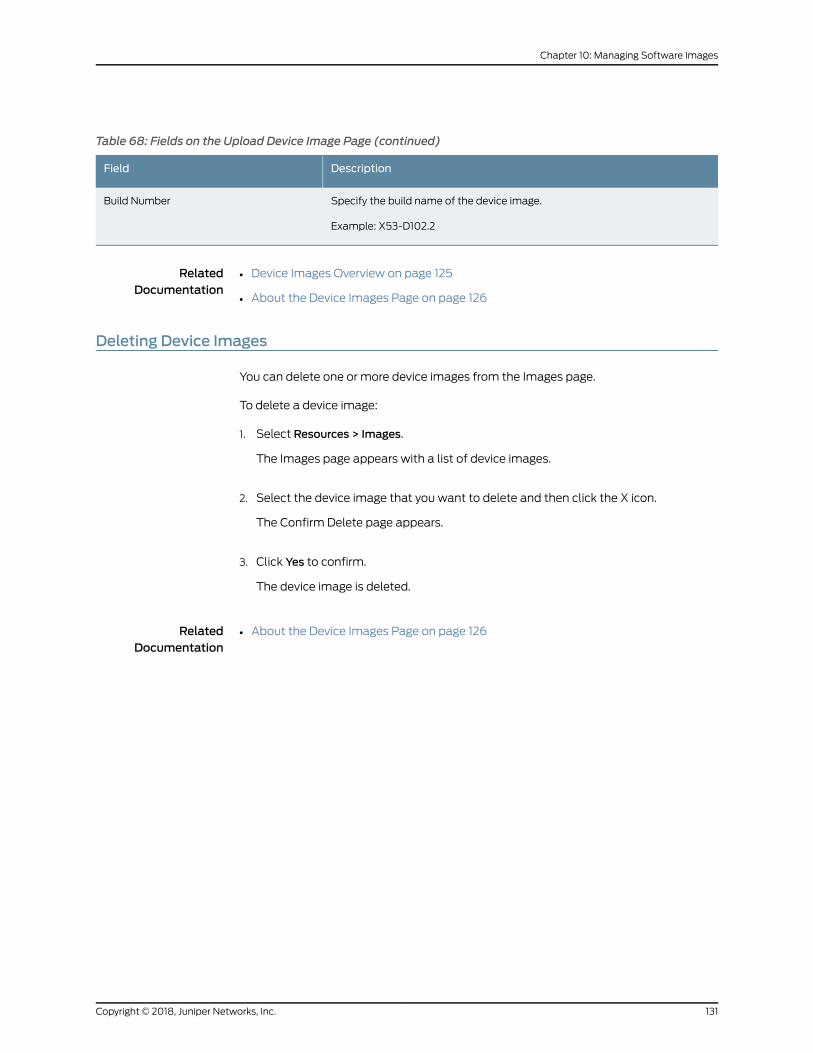
Table 68: Fields on the Upload Device Image Page (continued)
DescriptionField
Specify the build name of the device image.
Example: X53-D102.2
Build Number
RelatedDocumentation
Device Images Overview on page 125•
• About the Device Images Page on page 126
Deleting Device Images
You can delete one or more device images from the Images page.
To delete a device image:
1. Select Resources > Images.
The Images page appears with a list of device images.
2. Select the device image that you want to delete and then click the X icon.
The Confirm Delete page appears.
3. Click Yes to confirm.
The device image is deleted.
RelatedDocumentation
• About the Device Images Page on page 126
131Copyright © 2018, Juniper Networks, Inc.
Chapter 10: Managing Software Images

Copyright © 2018, Juniper Networks, Inc.132
Contrail Service Orchestration User Guide
CHAPTER 11
Configuring Network Services
• Network Services Overview on page 133
• About the Network Services Page on page 134
• About the Service Overview Page on page 136
• About the Service Instances Page on page 137
• Configuring VNF Properties on page 139
• Allocating a Service to Tenants on page 139
• Removing a Service from Tenants on page 140
• Viewing a Service Configuration on page 140
• vSRX VNF Configuration Settings on page 141
• LxCIPtable VNF Configuration Settings on page 148
• Cisco CSR-1000v VNF Configuration Settings on page 151
• Riverbed Steelhead VNF Configuration Settings on page 152
• Managing a Single Service on page 153
Network Services Overview
A network service is a final product offered to end users with a full description of its
functionality and specified performance.
Administrative users deploy network services between two locations in a virtual network,
so that traffic traveling in a specific direction on that link is subject to action from that
service. The term network service is defined in the ETSI Network Functions Virtualization
(NFV) standard.
A network service consists of a service chain of one or more linked network functions,
which are provided by specific virtualized network functions (VNFs), with a defined
direction for traffic flow and defined ingress and egress points. The term service chain
refers to the structure of a network service, and although not defined in the ETSI NFV
standard, this term is regularly used in NFV and software-defined networking (SDN).
A network service designer creates network services in Network Service Designer. When
the designer publishes the service to the network service catalog from Network Service
Designer, administrators can see the network service in Administration Portal.
133Copyright © 2018, Juniper Networks, Inc.
RelatedDocumentation
About the Network Services Page on page 134•
About the Network Services Page
To access this page, click Configuration > Network Services.
You can use the Services page to view the complete list of network services that service
designers have published to the network service catalog from Network Service Designer
and to view information about the services. For an introduction to network services, see
“Network Services Overview” on page 133.
Tasks You Can Perform
You can perform the following tasks from this page:
• Quickly view important data about services and about instances of those services
deployed at customers’ sites in the widgets that appear at the top of the page. See
Table 69 on page 134.
• Assign a service to one or more tenants. See “Allocating a Service to Tenants” on
page 139.
• Remove a service from one or more tenants. See “Removing a Service from Tenants”
on page 140.
• View full information about a service and about instances of a service at customer
sites. Click the name of a service in the list. See “About the Service Instances Page” on
page 137.
Field Descriptions
Table 69 on page 134 shows the descriptions of thewidgets that appear at the top of the
Services page.
Table 69:Widgets on the Services Page
DescriptionWidget
View the numbers of instances of the three services that are most used by tenants inthe network.
This viewmight help you to identify trends for network services, especially when youintroduce a new service.
Top Network Services Used
View the top three network services that are receiving maximum number of criticalalerts in the network.
Services with Critical Alerts
View the top three network services that are using the largest percentage of CPU fromthe assigned cores in the network.
Top Services by POP CPU Usage
Table 70 on page 135 shows the descriptions of the fields on the Network Services page.
Copyright © 2018, Juniper Networks, Inc.134
Contrail Service Orchestration User Guide
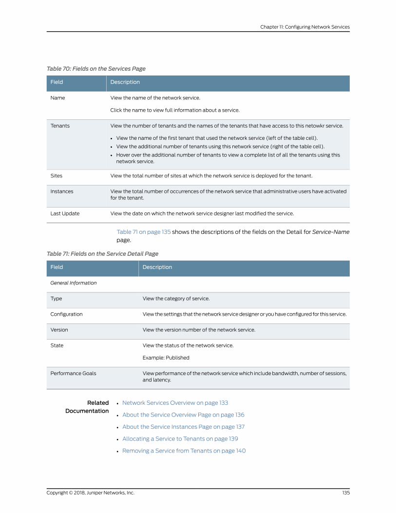
Table 70: Fields on the Services Page
DescriptionField
View the name of the network service.
Click the name to view full information about a service.
Name
View the number of tenants and the names of the tenants that have access to this netowkr service.
• View the name of the first tenant that used the network service (left of the table cell).
• View the additional number of tenants using this network service (right of the table cell).
• Hover over the additional number of tenants to view a complete list of all the tenants using thisnetwork service.
Tenants
View the total number of sites at which the network service is deployed for the tenant.Sites
View the total number of occurrences of the network service that administrative users have activatedfor the tenant.
Instances
View the date on which the network service designer last modified the service.Last Update
Table 71 on page 135 shows the descriptions of the fields on the Detail for Service-Name
page.
Table 71: Fields on the Service Detail Page
DescriptionField
General Information
View the category of service.Type
Viewthesettings that thenetwork servicedesigneror youhaveconfigured for this service.Configuration
View the version number of the network service.Version
View the status of the network service.
Example: Published
State
Viewperformanceof the network servicewhich includebandwidth, number of sessions,and latency.
Performance Goals
RelatedDocumentation
Network Services Overview on page 133•
• About the Service Overview Page on page 136
• About the Service Instances Page on page 137
• Allocating a Service to Tenants on page 139
• Removing a Service from Tenants on page 140
135Copyright © 2018, Juniper Networks, Inc.
Chapter 11: Configuring Network Services
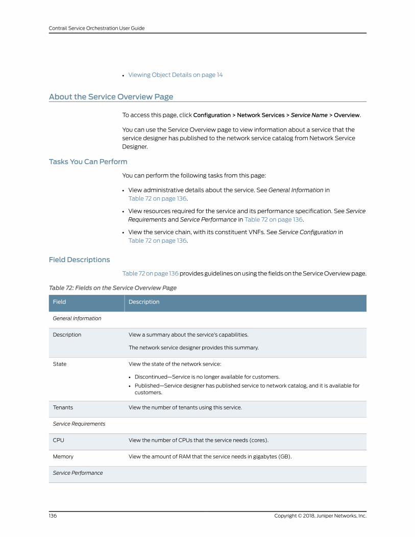
• Viewing Object Details on page 14
About the Service Overview Page
To access this page, click Configuration > Network Services > Service Name >Overview.
You can use the Service Overview page to view information about a service that the
service designer has published to the network service catalog from Network Service
Designer.
Tasks You Can Perform
You can perform the following tasks from this page:
• View administrative details about the service. See General Information in
Table 72 on page 136.
• View resources required for the service and its performance specification. See Service
Requirements and Service Performance in Table 72 on page 136.
• View the service chain, with its constituent VNFs. See Service Configuration in
Table 72 on page 136.
Field Descriptions
Table72onpage 136providesguidelinesonusing the fieldson theServiceOverviewpage.
Table 72: Fields on the Service Overview Page
DescriptionField
General Information
View a summary about the service’s capabilities.
The network service designer provides this summary.
Description
View the state of the network service:
• Discontinued—Service is no longer available for customers.
• Published—Service designer has published service to network catalog, and it is available forcustomers.
State
View the number of tenants using this service.Tenants
Service Requirements
View the number of CPUs that the service needs (cores).CPU
View the amount of RAM that the service needs in gigabytes (GB).Memory
Service Performance
Copyright © 2018, Juniper Networks, Inc.136
Contrail Service Orchestration User Guide
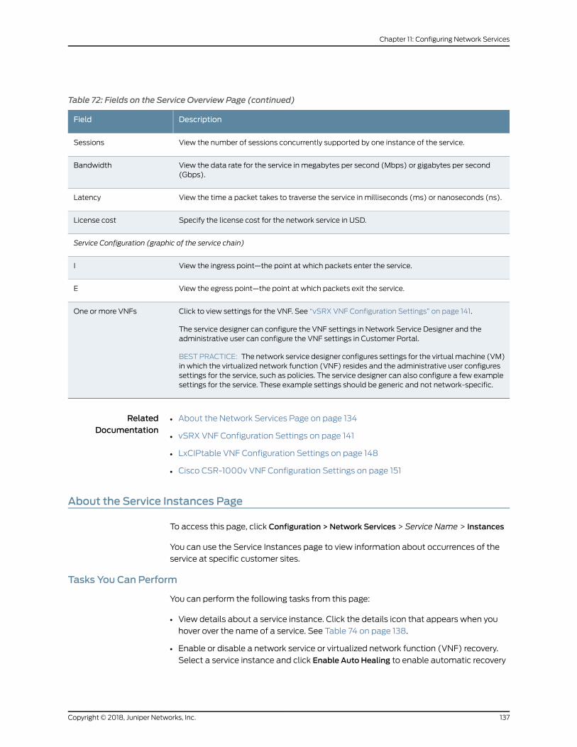
Table 72: Fields on the Service Overview Page (continued)
DescriptionField
View the number of sessions concurrently supported by one instance of the service.Sessions
View the data rate for the service in megabytes per second (Mbps) or gigabytes per second(Gbps).
Bandwidth
View the time a packet takes to traverse the service in milliseconds (ms) or nanoseconds (ns).Latency
Specify the license cost for the network service in USD.License cost
Service Configuration (graphic of the service chain)
View the ingress point—the point at which packets enter the service.I
View the egress point—the point at which packets exit the service.E
Click to view settings for the VNF. See “vSRX VNF Configuration Settings” on page 141.
The service designer can configure the VNF settings in Network Service Designer and theadministrative user can configure the VNF settings in Customer Portal.
BESTPRACTICE: The network service designer configures settings for the virtualmachine (VM)in which the virtualized network function (VNF) resides and the administrative user configuressettings for the service, such as policies. The service designer can also configure a few examplesettings for the service. These example settings should be generic and not network-specific.
One or more VNFs
RelatedDocumentation
About the Network Services Page on page 134•
• vSRX VNF Configuration Settings on page 141
• LxCIPtable VNF Configuration Settings on page 148
• Cisco CSR-1000v VNF Configuration Settings on page 151
About the Service Instances Page
To access this page, click Configuration > Network Services > Service Name > Instances
You can use the Service Instances page to view information about occurrences of the
service at specific customer sites.
Tasks You Can Perform
You can perform the following tasks from this page:
• View details about a service instance. Click the details icon that appears when you
hover over the name of a service. See Table 74 on page 138.
• Enable or disable a network service or virtualized network function (VNF) recovery.
Select a service instance and click Enable Auto Healing to enable automatic recovery
137Copyright © 2018, Juniper Networks, Inc.
Chapter 11: Configuring Network Services
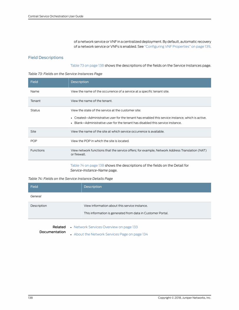
ofanetwork serviceorVNF inacentralizeddeployment.Bydefault, automatic recovery
of a network service or VNFs is enabled. See “Configuring VNFProperties” on page 139.
Field Descriptions
Table 73 on page 138 shows the descriptions of the fields on the Service Instances page.
Table 73: Fields on the Service Instances Page
DescriptionField
View the name of the occurrence of a service at a specific tenant site.Name
View the name of the tenant.Tenant
View the state of the service at the customer site:
• Created—Administrative user for the tenant has enabled this service instance, which is active.
• Blank—Administrative user for the tenant has disabled this service instance.
Status
View the name of the site at which service occurrence is available.Site
View the POP in which the site is located.POP
View network functions that the service offers; for example, Network Address Translation (NAT)or firewall.
Functions
Table 74 on page 138 shows the descriptions of the fields on the Detail for
Service-Instance-Name page.
Table 74: Fields on the Service Instance Details Page
DescriptionField
General
View information about this service instance.
This information is generated from data in Customer Portal.
Description
RelatedDocumentation
Network Services Overview on page 133•
• About the Network Services Page on page 134
Copyright © 2018, Juniper Networks, Inc.138
Contrail Service Orchestration User Guide
Configuring VNF Properties
You can specify whether to enable automatic recovery of a network service or virtualized
network function (VNF) for a network service instance in a centralized deployment.
Enabling automatic recovery of a network service or VNF improves reliability of the
implementation.
Conversely, disablingautomatic recoveryof anetwork serviceorVNFallowsyou toquickly
investigate a problemwith a network service or VNF itself.
To enable or disable automatic recovery of a network service or VNF:
1. Select Configuration > Network Services > Services Name > Instances.
The Services Instances page appears.
2. Select a service instance for which you want to enable or disable automatic recovery.
3. Click Enable Auto Healing.
The Service Properties page appears.
4. Select whether you want to enable or disable automatic recovery.
NOTE: By default, automatic recovery of a network service or VNF isenabled.
5. Click Save.
RelatedDocumentation
About the Service Instances Page on page 137•
Allocating a Service to Tenants
For a tenant to have access to a service, youmust assign the service to the tenant. You
can assign a service to multiple tenants simultaneously; however, you can assign only
one service at a time.
To assign a service to tenants:
1. Select Configuration > Network Services.
The Network Services page appears.
2. Select the service that you want to assign to the tenants.
139Copyright © 2018, Juniper Networks, Inc.
Chapter 11: Configuring Network Services
3. Click Allocate Services.
The Tenants: Select Tenant(s) to allocate the Service page appears.
4. Select the tenants to which you want to assign the service.
5. ClickOK to save the changes.
RelatedDocumentation
About the Network Services Page on page 134•
• Removing a Service from Tenants on page 140
Removing a Service from Tenants
You can remove a service fromone ormore tenants simultaneously. You can only remove
one service at a time, however.
To remove a service from tenants:
1. Click Configuration > Network Services.
The Network Services page appears.
2. Select the service that you want to remove from the tenants.
3. Click Detach Services.
The Detach Service from Tenants page appears.
4. Select the tenants fromwhich you want to remove the service.
5. ClickOk.
RelatedDocumentation
About the Network Services Page on page 134•
• Allocating a Service to Tenants on page 139
Viewing a Service Configuration
The following personnel can configure network services.
• The network service designer can configure a service in Network Service Designer.
• The administrative user for the tenant can configure a service in Customer Portal.
Settings that the administrative user configures override any settings that the network
service designer or administrator configure.
Copyright © 2018, Juniper Networks, Inc.140
Contrail Service Orchestration User Guide
BEST PRACTICE: The network service designer configures settings for thevirtualmachine (VM) inwhich thevirtualizednetwork function (VNF) residesandtheadministrativeuserconfiguressettings for theservice, suchaspolicies.Theservicedesigner canalsoconfigurea fewexamplesettings for theservice.These example settings should be generic and not network-specific.
To configure a service:
1. Select Configuration > Network Services > Service Name >Overview.
The Services Overview page for the service that you selected appears.
2. In the service chain graphic, click the first VNF.
The Service page appears.
3. Click each tab to review the settings.
TheBaseConfigure tab shows the settings for the virtualmachine (VM) that contains
the VNF, and the other tabs show the settings for specific functions in the VNF.
Refer to the related topics for the specific VNF settings for details on the configuration
settings.
4. (Optional) Click the next VNF in the service chain graphic to view settings for that
VNF.
5. ClickOk.
RelatedDocumentation
vSRX VNF Configuration Settings on page 141•
• LxCIPtable VNF Configuration Settings on page 148
• Cisco CSR-1000v VNF Configuration Settings on page 151
vSRX VNF Configuration Settings
You can configure the vSRX VNF from Configuration > Network Services > Service Name
>Overview>ServiceConfiguration. Your service provider usually configures base settings
for the virtualmachine (VM) inwhich the virtualized network function (VNF) resides and
you configure settings for the service, such as policies.
NOTE: A vSRX firewall virtualized network function (VNF) is always part ofa service chain for a network service on a CPE device.
NOTE: vSRX is the GWR for an on-premise CPE device.
Use the information in the following tables to provide values for the available settings:
141Copyright © 2018, Juniper Networks, Inc.
Chapter 11: Configuring Network Services
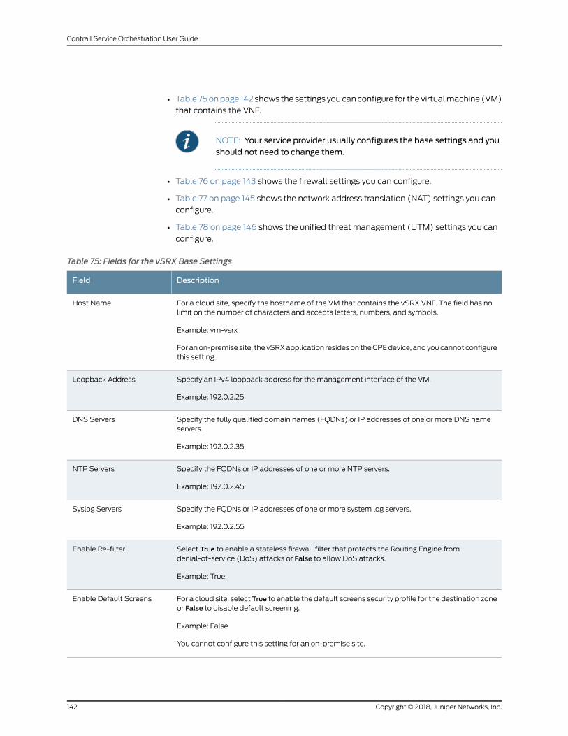
• Table 75onpage 142 shows the settings youcanconfigure for the virtualmachine (VM)
that contains the VNF.
NOTE: Your service provider usually configures the base settings and youshould not need to change them.
• Table 76 on page 143 shows the firewall settings you can configure.
• Table 77 on page 145 shows the network address translation (NAT) settings you can
configure.
• Table 78 on page 146 shows the unified threat management (UTM) settings you can
configure.
Table 75: Fields for the vSRX Base Settings
DescriptionField
For a cloud site, specify the hostname of the VM that contains the vSRX VNF. The field has nolimit on the number of characters and accepts letters, numbers, and symbols.
Example: vm-vsrx
Foranon-premisesite, thevSRXapplication resideson theCPEdevice, andyoucannotconfigurethis setting.
Host Name
Specify an IPv4 loopback address for the management interface of the VM.
Example: 192.0.2.25
Loopback Address
Specify the fully qualified domain names (FQDNs) or IP addresses of one or more DNS nameservers.
Example: 192.0.2.35
DNS Servers
Specify the FQDNs or IP addresses of one or more NTP servers.
Example: 192.0.2.45
NTP Servers
Specify the FQDNs or IP addresses of one or more system log servers.
Example: 192.0.2.55
Syslog Servers
Select True to enable a stateless firewall filter that protects the Routing Engine fromdenial-of-service (DoS) attacks or False to allow DoS attacks.
Example: True
Enable Re-filter
For a cloud site, select True to enable the default screens security profile for the destination zoneor False to disable default screening.
Example: False
You cannot configure this setting for an on-premise site.
Enable Default Screens
Copyright © 2018, Juniper Networks, Inc.142
Contrail Service Orchestration User Guide
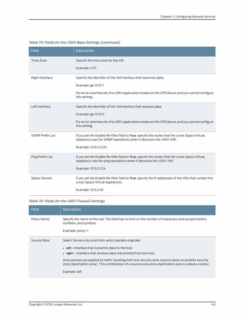
Table 75: Fields for the vSRX Base Settings (continued)
DescriptionField
Specify the time zone for the VM.
Example: UTC
Time Zone
Specify the identifier of the VM interface that transmits data.
Example: ge-0/0/1
Foranon-premisesite, thevSRXapplication resideson theCPEdevice, andyoucannotconfigurethis setting.
Right Interface
Specify the identifier of the VM interface that receives data.
Example: ge-0/0/0
Foranon-premisesite, thevSRXapplication resideson theCPEdevice, andyoucannotconfigurethis setting.
Left Interface
If you set the Enable Re-filter field to True, specify the routes that the Junos Space VirtualAppliance uses for SNMP operations when it discovers the vSRX VNF.
Example: 10.0.2.0/24
SNMP Prefix List
If you set the Enable Re-filter field to True, specify the routes that the Junos Space VirtualAppliance uses for ping operations when it discovers the vSRX VNF.
Example: 10.0.2.1/24
Ping Prefix List
If you set the Enable Re-filter field to True, specify the IP addresses of the VMs that contain theJunos Space Virtual Appliances.
Example: 10.0.2.50
Space Servers
Table 76: Fields for the vSRX Firewall Settings
DescriptionField
Specify the name of the rule. The field has no limit on the number of characters and accepts letters,numbers, and symbols.
Example: policy-1
Policy Name
Select the security zone fromwhich packets originate.
• left—Interface that transmits data to the host
• right— Interface that receives data transmitted from the host
Zone policies are applied to traffic traveling from one security zone (source zone) to another securityzone (destination zone). This combination of a source zone and a destination zone is called a context.
Example: left
Source Zone
143Copyright © 2018, Juniper Networks, Inc.
Chapter 11: Configuring Network Services

Table 76: Fields for the vSRX Firewall Settings (continued)
DescriptionField
Select the security zone to which packets are delivered.
• left—Interface that transmits data to the host
• right—Interface that receives data transmitted from the host
Zone policies are applied to traffic traveling from one security zone (source zone) to another securityzone (destination zone). This combination of a source zone and a destination zone is called a context.
Example: right
Destination Zone
Specify the source IP address prefixes that the network service uses asmatch criteria for incoming traffic.
To add source addresses:
1. Click the Source Address column.
The source-address page appears.
2. Select any to match any source IP address of packets or ipp to match a specific prefix in the sourceIP address for which the application enforces the policy.
3. If you select ipp, specify a prefix.
4. ClickOK.
Example: 10.0.2.30
Source Address
Specify the destination IP address prefixes that the network service uses as match criteria for outgoingtraffic.
To add a destination address:
1. Click the Destination Address column.
The destination-address page appears.
2. Select any to match any source IP address of packets or ipp to match a specific prefix in the sourceIP address for which the application enforces the policy.
3. If you select ipp, specify a prefix.
4. ClickOK.
Example: 192.0.2.0/24
DestinationAddress
Select permit to transmit packets that match the rule or deny to drop packets that match the rule.
Example: permit
Action
Copyright © 2018, Juniper Networks, Inc.144
Contrail Service Orchestration User Guide
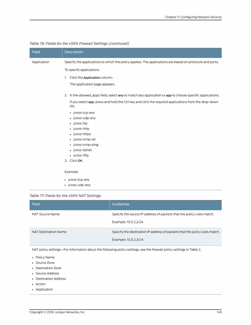
Table 76: Fields for the vSRX Firewall Settings (continued)
DescriptionField
Specify the applications to which the policy applies. The applications are based on protocols and ports.
To specify applications:
1. Click the Application column.
The application page appears.
2. In the allowed_apps field, select any to match any application or app to choose specific applications.
If you select app, press and hold the Ctrl key and click the required applications from the drop-downlist.
• junos-tcp-any
• junos-udp-any
• junos-ftp
• junos-http
• junos-https
• junos-icmp-all
• junos-icmp-ping
• junos-telnet
• junos-tftp
3. ClickOK.
Example:
• junos-tcp-any
• junos-udp-any
Application
Table 77: Fields for the vSRX NAT Settings
GuidelinesField
Specify the source IP address of packets that the policy rules match.
Example: 10.0.2.2/24
NAT Source Name
Specify the destination IP address of packets that the policy rulesmatch.
Example: 10.0.2.3/24
NAT Destination Name
NAT policy settings—For information about the following policy settings, see the firewall policy settings in Table 2.
• Policy Name
• Source Zone
• Destination Zone
• Source Address
• Destination Address
• Action
• Application
145Copyright © 2018, Juniper Networks, Inc.
Chapter 11: Configuring Network Services
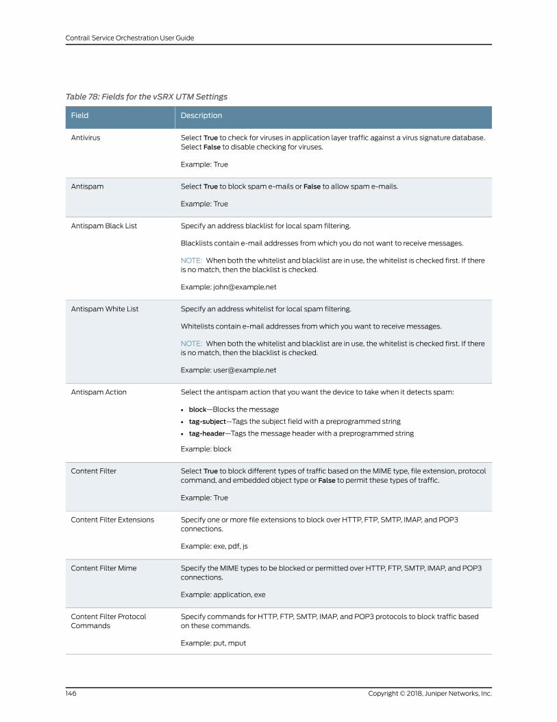
Table 78: Fields for the vSRX UTMSettings
DescriptionField
Select True to check for viruses in application layer traffic against a virus signature database.Select False to disable checking for viruses.
Example: True
Antivirus
Select True to block spam e-mails or False to allow spam e-mails.
Example: True
Antispam
Specify an address blacklist for local spam filtering.
Blacklists contain e-mail addresses fromwhich you do not want to receive messages.
NOTE: When both the whitelist and blacklist are in use, the whitelist is checked first. If thereis nomatch, then the blacklist is checked.
Example: [email protected]
Antispam Black List
Specify an address whitelist for local spam filtering.
Whitelists contain e-mail addresses fromwhich you want to receive messages.
NOTE: When both the whitelist and blacklist are in use, the whitelist is checked first. If thereis nomatch, then the blacklist is checked.
Example: [email protected]
AntispamWhite List
Select the antispam action that you want the device to take when it detects spam:
• block—Blocks the message
• tag-subject—Tags the subject field with a preprogrammed string
• tag-header—Tags themessage header with a preprogrammed string
Example: block
Antispam Action
Select True to block different types of traffic based on the MIME type, file extension, protocolcommand, and embedded object type or False to permit these types of traffic.
Example: True
Content Filter
Specify one or more file extensions to block over HTTP, FTP, SMTP, IMAP, and POP3connections.
Example: exe, pdf, js
Content Filter Extensions
Specify the MIME types to be blocked or permitted over HTTP, FTP, SMTP, IMAP, and POP3connections.
Example: application, exe
Content Filter Mime
Specify commands for HTTP, FTP, SMTP, IMAP, and POP3 protocols to block traffic basedon these commands.
Example: put, mput
Content Filter ProtocolCommands
Copyright © 2018, Juniper Networks, Inc.146
Contrail Service Orchestration User Guide
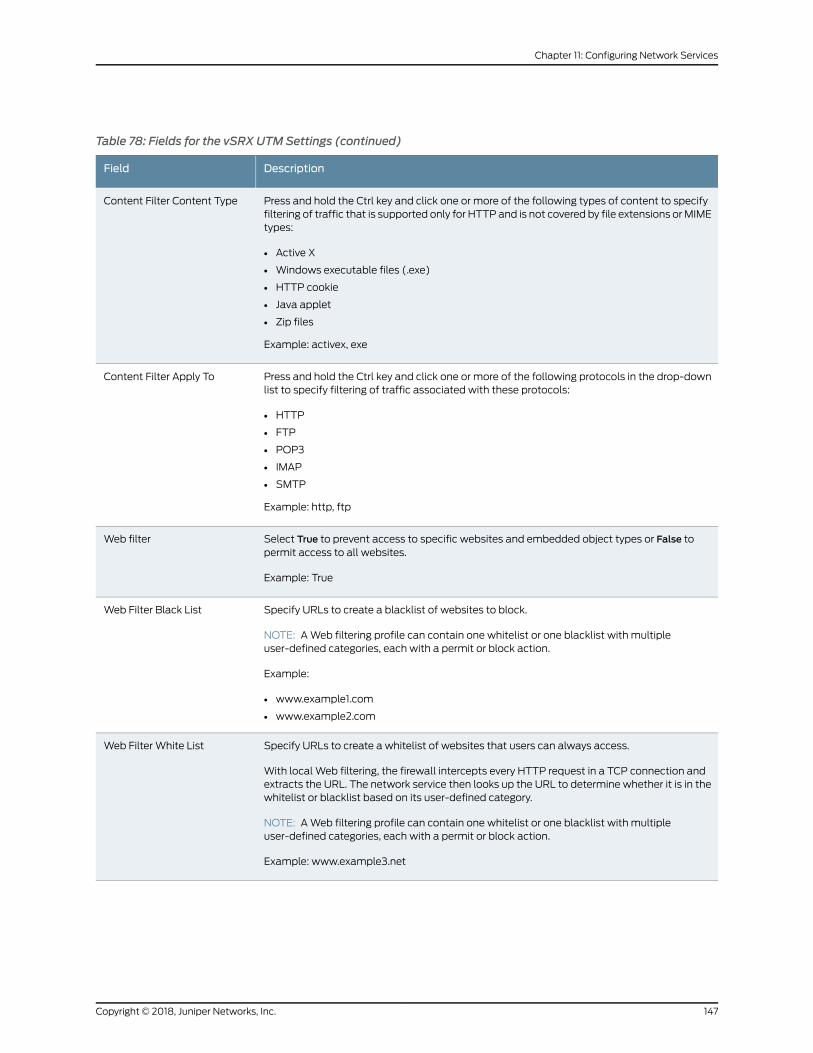
Table 78: Fields for the vSRX UTMSettings (continued)
DescriptionField
Press and hold the Ctrl key and click one or more of the following types of content to specifyfiltering of traffic that is supported only for HTTP and is not covered by file extensions orMIMEtypes:
• Active X
• Windows executable files (.exe)
• HTTP cookie
• Java applet
• Zip files
Example: activex, exe
Content Filter Content Type
Press and hold the Ctrl key and click one or more of the following protocols in the drop-downlist to specify filtering of traffic associated with these protocols:
• HTTP
• FTP
• POP3
• IMAP
• SMTP
Example: http, ftp
Content Filter Apply To
Select True to prevent access to specific websites and embedded object types or False topermit access to all websites.
Example: True
Web filter
Specify URLs to create a blacklist of websites to block.
NOTE: AWeb filtering profile can contain one whitelist or one blacklist with multipleuser-defined categories, each with a permit or block action.
Example:
• www.example1.com
• www.example2.com
Web Filter Black List
Specify URLs to create a whitelist of websites that users can always access.
With local Web filtering, the firewall intercepts every HTTP request in a TCP connection andextracts the URL. The network service then looks up the URL to determine whether it is in thewhitelist or blacklist based on its user-defined category.
NOTE: AWeb filtering profile can contain one whitelist or one blacklist with multipleuser-defined categories, each with a permit or block action.
Example: www.example3.net
Web Filter White List
147Copyright © 2018, Juniper Networks, Inc.
Chapter 11: Configuring Network Services
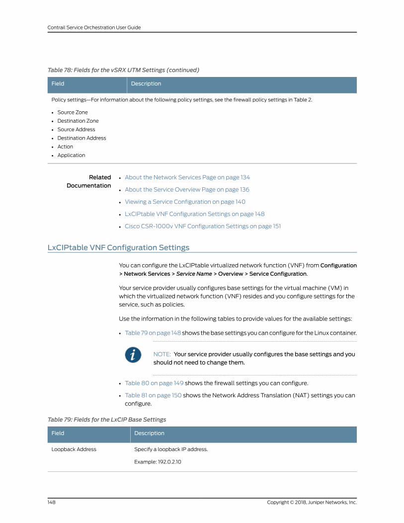
Table 78: Fields for the vSRX UTMSettings (continued)
DescriptionField
Policy settings—For information about the following policy settings, see the firewall policy settings in Table 2.
• Source Zone
• Destination Zone
• Source Address
• Destination Address
• Action
• Application
RelatedDocumentation
About the Network Services Page on page 134•
• About the Service Overview Page on page 136
• Viewing a Service Configuration on page 140
• LxCIPtable VNF Configuration Settings on page 148
• Cisco CSR-1000v VNF Configuration Settings on page 151
LxCIPtable VNF Configuration Settings
You can configure the LxCIPtable virtualized network function (VNF) from Configuration
> Network Services > Service Name >Overview > Service Configuration.
Your service provider usually configures base settings for the virtual machine (VM) in
which the virtualized network function (VNF) resides and you configure settings for the
service, such as policies.
Use the information in the following tables to provide values for the available settings:
• Table 79onpage 148shows thebase settings youcanconfigure for theLinux container.
NOTE: Your service provider usually configures the base settings and youshould not need to change them.
• Table 80 on page 149 shows the firewall settings you can configure.
• Table 81 on page 150 shows the Network Address Translation (NAT) settings you can
configure.
Table 79: Fields for the LxCIP Base Settings
DescriptionField
Specify a loopback IP address.
Example: 192.0.2.10
Loopback Address
Copyright © 2018, Juniper Networks, Inc.148
Contrail Service Orchestration User Guide
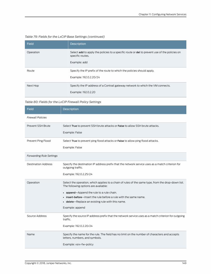
Table 79: Fields for the LxCIP Base Settings (continued)
DescriptionField
Select add to apply the policies to a specific route or del to prevent use of the policies onspecific routes.
Example: add
Operation
Specify the IP prefix of the route to which the policies should apply.
Example: 192.0.2.20/24
Route
Specify the IP address of a Contrail gateway network to which the VM connects.
Example: 192.0.2.20
Next Hop
Table 80: Fields for the LxCIP Firewall Policy Settings
DescriptionField
Firewall Policies
Select True to prevent SSH brute attacks or False to allow SSH brute attacks.
Example: False
Prevent SSH Brute
Select True to prevent ping flood attacks or False to allow ping flood attacks.
Example: False
Prevent Ping Flood
Forwarding Rule Settings
Specify the destination IP address prefix that the network service uses as amatch criterion foroutgoing traffic.
Example: 192.0.2.25/24
Destination Address
Select the operation, which applies to a chain of rules of the same type, from the drop-down list.The following options are available:
• append—Append the rule to a rule chain.
• insert-before—Insert the rule before a rule with the same name.
• delete—Replace an existing rule with this name.
Example: append
Operation
Specify the source IP address prefix that the network service uses as amatch criterion for outgoingtraffic.
Example: 192.0.2.20/24
Source Address
Specify the name for the rule. The field has no limit on the number of characters and acceptsletters, numbers, and symbols.
Example: vsrx-fw-policy
Name
149Copyright © 2018, Juniper Networks, Inc.
Chapter 11: Configuring Network Services
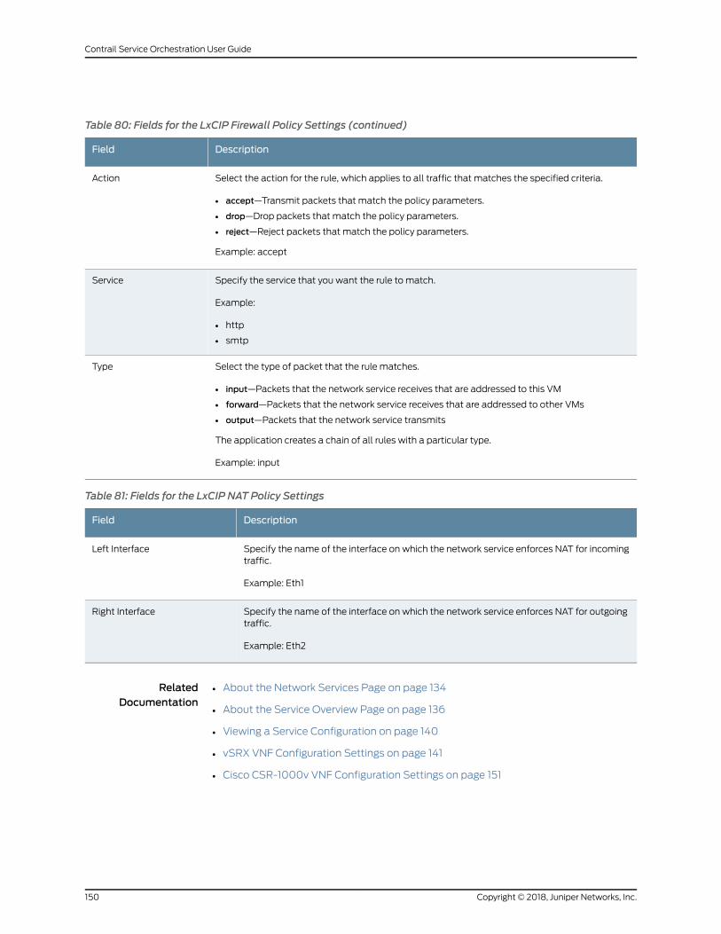
Table 80: Fields for the LxCIP Firewall Policy Settings (continued)
DescriptionField
Select the action for the rule, which applies to all traffic that matches the specified criteria.
• accept—Transmit packets that match the policy parameters.
• drop—Drop packets that match the policy parameters.
• reject—Reject packets that match the policy parameters.
Example: accept
Action
Specify the service that you want the rule to match.
Example:
• http
• smtp
Service
Select the type of packet that the rule matches.
• input—Packets that the network service receives that are addressed to this VM
• forward—Packets that the network service receives that are addressed to other VMs
• output—Packets that the network service transmits
The application creates a chain of all rules with a particular type.
Example: input
Type
Table 81: Fields for the LxCIP NAT Policy Settings
DescriptionField
Specify the name of the interface on which the network service enforces NAT for incomingtraffic.
Example: Eth1
Left Interface
Specify the name of the interface on which the network service enforces NAT for outgoingtraffic.
Example: Eth2
Right Interface
RelatedDocumentation
About the Network Services Page on page 134•
• About the Service Overview Page on page 136
• Viewing a Service Configuration on page 140
• vSRX VNF Configuration Settings on page 141
• Cisco CSR-1000v VNF Configuration Settings on page 151
Copyright © 2018, Juniper Networks, Inc.150
Contrail Service Orchestration User Guide
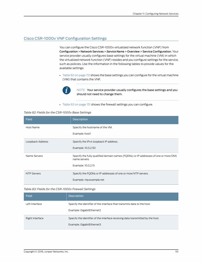
Cisco CSR-1000v VNF Configuration Settings
You can configure the Cisco CSR-1000v virtualized network function (VNF) from
Configuration>NetworkServices >ServiceName>Overview>ServiceConfiguration. Your
service provider usually configures base settings for the virtual machine (VM) in which
the virtualized network function (VNF) resides and you configure settings for the service,
such as policies. Use the information in the following tables to provide values for the
available settings:
• Table 82 on page 151 shows the base settings you can configure for the virtualmachine
(VM) that contains the VNF.
NOTE: Your service provider usually configures the base settings and youshould not need to change them.
• Table 83 on page 151 shows the firewall settings you can configure.
Table 82: Fields for the CSR-1000v Base Settings
DescriptionField
Specify the hostname of the VM.
Example: host1
Host Name
Specify the IPv4 loopback IP address.
Example: 10.0.2.50
Loopback Address
Specify the fully qualified domain names (FQDNs) or IP addresses of one or more DNSname servers.
Example: 10.0.2.15
Name Servers
Specify the FQDNs or IP addresses of one or more NTP servers.
Example: ntp.example.net
NTP Servers
Table 83: Fields for the CSR-1000v Firewall Settings
DescriptionField
Specify the identifier of the interface that transmits data to the host.
Example: GigabitEthernet2
Left Interface
Specify the identifier of the interface receiving data transmitted by the host.
Example: GigabitEthernet3
Right Interface
151Copyright © 2018, Juniper Networks, Inc.
Chapter 11: Configuring Network Services
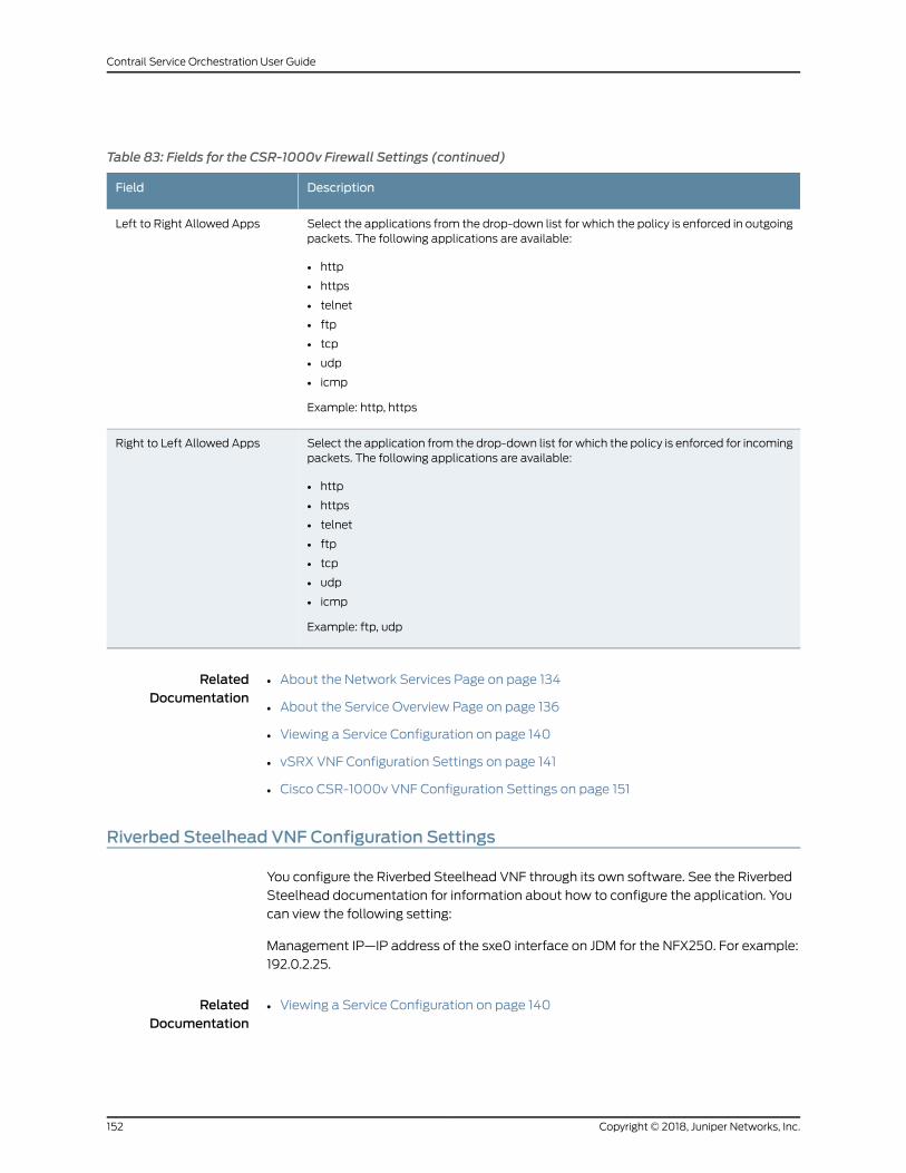
Table 83: Fields for the CSR-1000v Firewall Settings (continued)
DescriptionField
Select the applications from the drop-down list for which the policy is enforced in outgoingpackets. The following applications are available:
• http
• https
• telnet
• ftp
• tcp
• udp
• icmp
Example: http, https
Left to Right Allowed Apps
Select the application from the drop-down list for which the policy is enforced for incomingpackets. The following applications are available:
• http
• https
• telnet
• ftp
• tcp
• udp
• icmp
Example: ftp, udp
Right to Left Allowed Apps
RelatedDocumentation
About the Network Services Page on page 134•
• About the Service Overview Page on page 136
• Viewing a Service Configuration on page 140
• vSRX VNF Configuration Settings on page 141
• Cisco CSR-1000v VNF Configuration Settings on page 151
Riverbed Steelhead VNF Configuration Settings
You configure the Riverbed Steelhead VNF through its own software. See the Riverbed
Steelhead documentation for information about how to configure the application. You
can view the following setting:
Management IP—IP address of the sxe0 interface on JDM for the NFX250. For example:
192.0.2.25.
RelatedDocumentation
Viewing a Service Configuration on page 140•
Copyright © 2018, Juniper Networks, Inc.152
Contrail Service Orchestration User Guide
Managing a Single Service
Use the tabs on this page to view andmanage information about services and service
instances.
• About the Service Overview Page on page 136
• About the Service Instances Page on page 137
RelatedDocumentation
• About the Network Services Page on page 134
• Viewing a Service Configuration on page 140
153Copyright © 2018, Juniper Networks, Inc.
Chapter 11: Configuring Network Services

Copyright © 2018, Juniper Networks, Inc.154
Contrail Service Orchestration User Guide
CHAPTER 12
Configuring Application SLA Profiles
• Application Quality of Experience (AppQoE) Overview on page 155
• About the Application Traffic Type Profiles Page on page 157
• Creating Traffic Type Profiles on page 160
• Editing and Deleting Traffic Type Profiles on page 163
• SLA Profiles and SD-WAN Policies Overview on page 164
• Local Breakout Overview on page 167
• About the Application SLA Profiles Page on page 168
• Creating SLA Profiles on page 169
• Editing and Deleting SLA Profiles on page 171
Application Quality of Experience (AppQoE) Overview
Application Quality of Experience (AppQoE) aims to improve the user experience at the
application level by constantly monitoring the class-of -service parameters and SLA
compliance of application traffic and ensuring that the application data is sent over the
most SLA-compliant link available. AppQoE is supported on both hub-and-spoke and
full mesh topologies when the SD-WANmode is set to Real Time-Optimized. In Release
3.3, AppQoE is implemented as a book-ended solution, where both the ends have SRX
series devices or vSRX instances that run the same version of Junos OSwith the same
configuration.
AppQoE is enabled only when the SD-WANmode for the tenant is set to Real
Time-Optimized. In the default mode, which is Bandwidth-Optimized, CSO uses RPM
probes to monitor link-level traffic.
On SD-WANs in the real time-optimizedmode, CSOmonitors the application traffic for
SLA compliance. TheCPEdevice uses this data tomove the application traffic from links
that fail to meet the SLA requirements to links that meet SLA.
Tomonitor the SLA compliance of the link on which the application traffic is sent, CSO
sends inlineprobes, calledaspassiveprobes, alongwith theapplication traffic. To identify
the best available link for an application in case the active link fails to meet the SLA
criteria, CSO constantly monitors and collects SLA compliance data for other available
links. The probes that CSO sends over the other links to check the SLA compliance are
155Copyright © 2018, Juniper Networks, Inc.
called as active probes. The active probes are carried out based on the probe parameters
that you configure.
Link switching is done at the application level by the CPE device. That is, only the traffic
corresponding to the application that reported the SLA violation is moved to a link that
meets the specified SLA. The remaining traffic remains on the same link until those
applications report an SLA violation.
In Release 3.3 and later, you can configure traffic type profiles to specify the
class-of-service parameters and the probe parameters for each traffic type. When you
create an application SLA profile, you can link that with a traffic type profile and specify
the SLA parameters and SLA sampling criteria for the SLA profile.. The Application SLA
profile is then linked to an SD-WAN policy intent, which can be deployed to implement
AppQoE.
From the Application SLA Performance page, you can view the application-level SLA
performance information and whether AppQoE is enabled. You can also view
applications-level SLA performance details such as packet loss, RTT, jitter, and the
number of probes.
The followingsectionsdescribe theprerequisites, limitations, andworkflow for configuring
AppQoE.
• Limitations on page 156
• Workflow on page 156
Limitations
TheAppQoEsupport inRelease3.3 is subject to the following limitationsand restrictions:
• Only book-ended solutions, which have SRX devices or vSRX instances that run the
same version of Junos OSwith the same configuration on both ends, are supported.
• Multihoming is not supported.
• Dual CPE devices are not supported.
Workflow
This section provides a sequential list of tasks that you need to perform to configure and
monitor AppQoE:
1. Service provider administrators review the “Default Traffic Type Profiles” on page 157,
enable the required profiles, “modify the default profiles” on page 163, or “create new
profiles” on page 160.
2. Add a tenant with the SD-WANmode set to real time-optimized. For information
about adding a tenant, see “Adding a Single Tenant” on page 183.
3. Service provide administrator or tenant administrator can create an application SLA
profile and associate a traffic type profile with that. For more information about
creating an application SLA profile, see “Creating SLA Profiles” on page 169.
Copyright © 2018, Juniper Networks, Inc.156
Contrail Service Orchestration User Guide
4. Service provide administrator or tenant administrator can associate the SLA profile
with an SD-WAN Policy and deploy the policy. For more information see “Creating
SD-WAN Policy Intents” on page 441 and “Deploying Policies” on page 532.
5. Service provider administrator or tenant administrator can viewapplication-level SLA
performance details from the Application SLA Performance page. For more
information, see “Monitoring Application-Level SLA Performance for real
time-optimized SD-WAN” on page 36.
About the Application Traffic Type Profiles Page
To access this page from the Administration portal, select Configuration > Application
Traffic Type Profiles. To access this page from the Customer portal, select Configuration
> SD-WAN > Application Traffic Type Profiles.
You can use the Traffic Type Profiles page to configure class-of-service parameters for
various types of traffic. Traffic type profiles enable you to configure class-of-service
parameters based on your specific business requirements. Traffic type profiles enable
you to assign priority and service level criteria for traffic types. This topic contains the
following sections:
• Default Traffic Type Profiles on page 157
• Tasks You Can Perform on page 159
• Field Descriptions on page 159
Default Traffic Type Profiles
By default, CSO provides the following traffic type profiles:
• High-Priority-Video
• Premium-Internet
• Internet
• Hosted-AV
• Voice-Video
NOTE: Bydefault, these traffic typeprofilesaredisabled.CSPadministratorscan review and enable the profiles on a need-basis.
Table describes the default parameters for each of these traffic types.
157Copyright © 2018, Juniper Networks, Inc.
Chapter 12: Configuring Application SLA Profiles
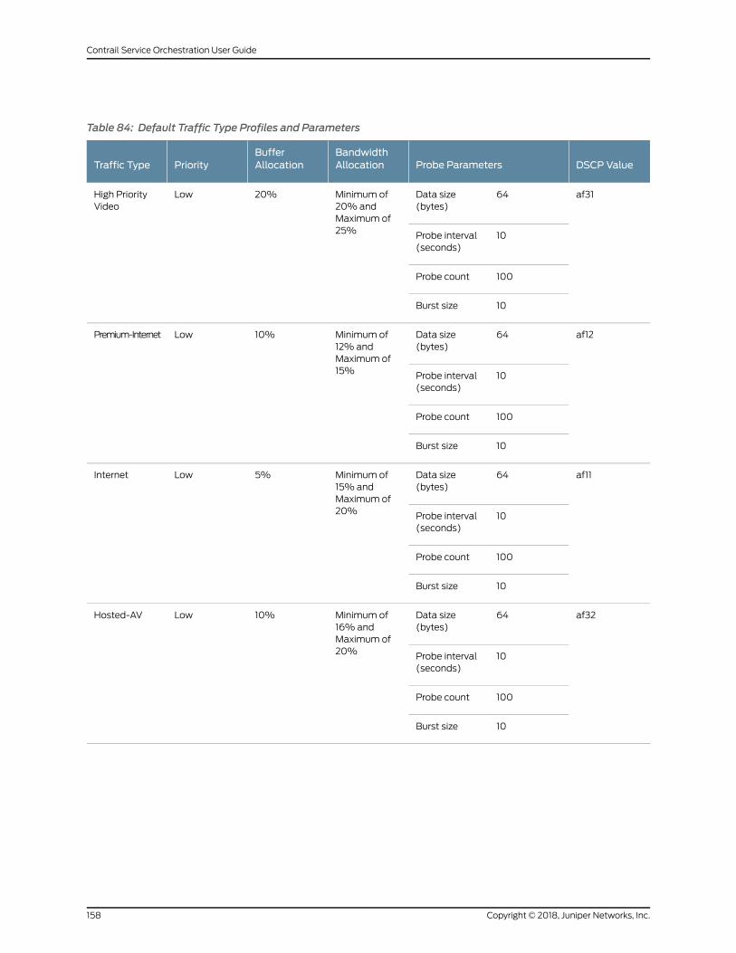
Table 84: Default Traffic Type Profiles and Parameters
DSCP ValueProbe ParametersBandwidthAllocation
BufferAllocationPriorityTraffic Type
af3164Data size(bytes)
Minimum of20% andMaximum of25%
20%LowHigh PriorityVideo
10Probe interval(seconds)
100Probe count
10Burst size
af1264Data size(bytes)
Minimum of12% andMaximum of15%
10%LowPremium-Internet
10Probe interval(seconds)
100Probe count
10Burst size
af1164Data size(bytes)
Minimum of15% andMaximum of20%
5%LowInternet
10Probe interval(seconds)
100Probe count
10Burst size
af3264Data size(bytes)
Minimum of16% andMaximum of20%
10%LowHosted-AV
10Probe interval(seconds)
100Probe count
10Burst size
Copyright © 2018, Juniper Networks, Inc.158
Contrail Service Orchestration User Guide
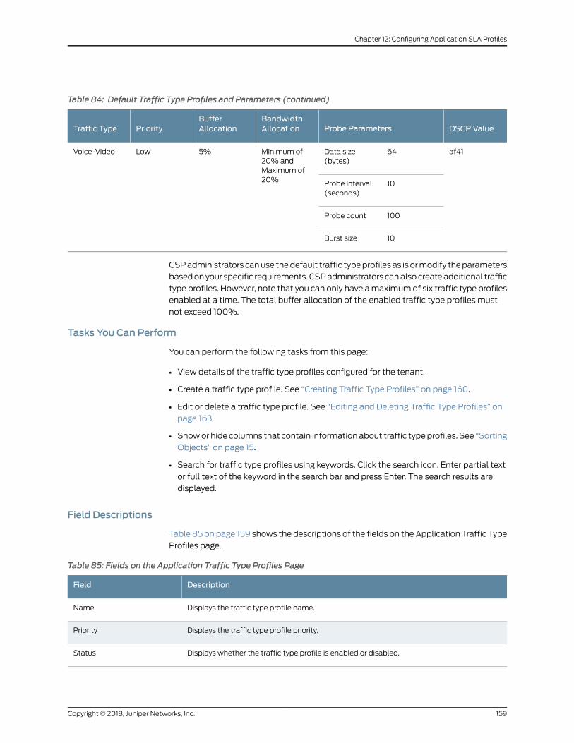
Table 84: Default Traffic Type Profiles and Parameters (continued)
DSCP ValueProbe ParametersBandwidthAllocation
BufferAllocationPriorityTraffic Type
af4164Data size(bytes)
Minimum of20% andMaximum of20%
5%LowVoice-Video
10Probe interval(seconds)
100Probe count
10Burst size
CSPadministrators canuse thedefault traffic typeprofilesas is ormodify theparameters
basedonyour specific requirements. CSPadministrators canalsocreateadditional traffic
type profiles. However, note that you can only have amaximumof six traffic type profiles
enabled at a time. The total buffer allocation of the enabled traffic type profiles must
not exceed 100%.
Tasks You Can Perform
You can perform the following tasks from this page:
• View details of the traffic type profiles configured for the tenant.
• Create a traffic type profile. See “Creating Traffic Type Profiles” on page 160.
• Edit or delete a traffic type profile. See “Editing and Deleting Traffic Type Profiles” on
page 163.
• Showor hide columns that contain information about traffic typeprofiles. See “Sorting
Objects” on page 15.
• Search for traffic type profiles using keywords. Click the search icon. Enter partial text
or full text of the keyword in the search bar and press Enter. The search results are
displayed.
Field Descriptions
Table 85 on page 159 shows the descriptions of the fields on the Application Traffic Type
Profiles page.
Table 85: Fields on the Application Traffic Type Profiles Page
DescriptionField
Displays the traffic type profile name.Name
Displays the traffic type profile priority.Priority
Displays whether the traffic type profile is enabled or disabled.Status
159Copyright © 2018, Juniper Networks, Inc.
Chapter 12: Configuring Application SLA Profiles
Table 85: Fields on the Application Traffic Type Profiles Page (continued)
DescriptionField
Shows the DSCP value assigned to the traffic type profile. Differentiated Services Code Point(DSCP)valuesdefine the forwardingpropertiesof thepacketwithin theDifferentiatedServicesframework.
DSCP Value
Shows theminimum andmaximum bandwidth allocation for the traffic type profile.Bandwidth
Shows the buffer allocation for the traffic type profile.Buffer
Shows the following probe parameters configured for the traffic type profile:
• Data Size (in bytes)
• Probe Interval (in seconds)
• Probe Count
• Burst Size
Probe Parameters
Shows the user that created the SLA profile.Created by
RelatedDocumentation
Creating Traffic Type Profiles on page 160•
• Editing and Deleting Traffic Type Profiles on page 163
Creating Traffic Type Profiles
You can use Traffic Type Profiles to configure class-of-service parameters for various
types of traffic. Traffic type profiles enable you to configure class-of-service parameters
based on your specific business requirements. Traffic type profiles enable you to assign
priority and service level criteria for traffic types. You can link an application traffic type
profile with an application SLA profile, which can be linked to an SD-WAN policy intent.
To create an “Application Traffic Type” on page 157 profile:
1. Select Configuration > SD-WAN > Application Traffic Type Profiles.
The Application Traffic Type Profiles page appears.
2. Click the Add (+) icon to create a new traffic type profile.
The Create New Traffic Type Profile page appears.
3. Configure the traffic type profile parameters as per the guidelines provide in
Table 86 on page 161.
4. ClickOK to save the traffic type profile configuration. If you want to discard your
changes, click Cancel instead.
Copyright © 2018, Juniper Networks, Inc.160
Contrail Service Orchestration User Guide
If you clickOK, the traffic type profiles that you configured appear on theApplication
Traffic Type Profiles page.
Table 86: Fields on the Create Traffic Type Profiles page
DescriptionField
General
Enter the name of the traffic type profile that you want to create. Can be a uniquestring of not more than 15 characters that contains alphanumeric characters andhyphen (-).
Name
Select the priority value that you want to assign to the traffic type profile. Traffic typeprofiles with higher priority values takes precedence over the ones with lower valueswhen network congestions occur.
NOTE: You cannot create two traffic type profiles with S-High or High priority.
The following list is arranged in the decreasing order of priority, where the first itemindicates the highest priority and the fifth item, the lowest priority.
1. S-High, which denotes strict high or the highest priority.
2. M-High, which denotes medium high.
3. High
4. M-Low, which denotes medium low.
5. Low
Priority
Click the toggle button to enable the traffic typeprofile. You canonly haveamaximumof six traffic profiles enabled at a time. You can assign only those traffic type profilesthat are marked as enabled to application SLA profiles.
NOTE: If therearemore thansix traffic typeprofiles enabledwhenyoudeployapolicy,the policy deployment fails.
Status
Probe Parameters
TIP: You can select one of the already configured traffic type profiles from the Copy probe parameters from list to populate thevalues in the probe parameters fields. When you select a traffic type profile, the probe parameter values associated with thatprofile are populated to the fields. You can edit the values if required. .
Specify the size of the data packets, in bytes, to be used for active probes. The rangeis 4 through 256.
Data Size
Specify the interval, in seconds, between two probes. The range is 1 through 10.Probe Interval
Specify the number of probes that form a test. The range from 10 through 1000.Probe Count
Specify themaximumnumber of probes that can be sent in one go. The range is from10 through 100.The value for this parametermust not exceed the value youconfiguredfor Probe Count.
Burst Size
Bandwidth
161Copyright © 2018, Juniper Networks, Inc.
Chapter 12: Configuring Application SLA Profiles
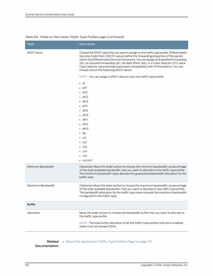
Table 86: Fields on the Create Traffic Type Profiles page (continued)
DescriptionField
Choose theDSCPvalue that youwant toassign to the traffic typeprofile. DifferentiatedServices Code Point (DSCP) values define the forwarding properties of the packetwithin theDifferentiatedServices framework.YoucanassignanExpeditedForwarding(ef), an Assured Forwarding (af), the Best Effort (be), or a Class Selector (CS) value.Class Selector value provides backward compatibility with IP Precedence. You canchoose one of the following DSCP values:
NOTE: You can assign a DSCP value to only one traffic type profile.
• ef
• af11
• af21
• af22
• af23
• af31
• af32
• af33
• af41
• af42
• af43
• be
• cs1
• cs2
• cs3
• cs4
• cs5
• nc2/cs7
DSCP Value
(Optional) Move the slider button to choose theminimum bandwidth, as percentageof the total available bandwidth, that you want to allocate to the traffic type profile.Theminimumbandwidth value denotes the guaranteed bandwidth allocation for thetraffic type.
Minimum Bandwidth
(Optional)Move the slider button to choose themaximumbandwidth, as percentageof the total available bandwidth, that you want to allocate to the traffic type profile.The bandwidth allocation for the traffic type never exceeds themaximumbandwidthconfigured for the traffic type.
Maximum Bandwidth
Buffer
Move the slider button to choose the bandwidth buffer that you want to allocate tothe traffic type profile.
NOTE: The total buffer allocation of all the traffic type profiles that are in enabledstate must not exceed 100%.
Allocation
RelatedDocumentation
About the Application Traffic Type Profiles Page on page 157•
Copyright © 2018, Juniper Networks, Inc.162
Contrail Service Orchestration User Guide
• Editing and Deleting Traffic Type Profiles on page 163
Editing and Deleting Traffic Type Profiles
You can edit and delete traffic type profile configuration.
The following sections explain the procedure for editing and deleting traffic type profiles:
• Editing Traffic Type Profiles on page 163
• Deleting Traffic Type Profiles on page 163
Editing Traffic Type Profiles
To edit a traffic type profile:
1. Select Configuration > SD-WAN > Application Traffic Type Profiles.
The Application Traffic Type Profiles page appears.
2. Select the check box that corresponds to the traffic type profile that you want to
modify and click the edit icon.
The Edit Traffic Type Profile page appears Modify the configuration as required. For
information about the parameters, see Table 86 on page 161.
4. ClickOK to save the changes. If youwant to discard your changes, clickCancel instead
Deleting Traffic Type Profiles
To delete a traffic type profile:
NOTE: You cannot delete a traffic type profile if the profile is associatedwithanapplicationSLAprofile. Youmust first edit the applicationSLAprofile andremove the association with the traffic type profile or delete the associatedapplication SLA profile.
1. Select Configuration > SD-WAN > Application Traffic Type Profiles.
The Application Traffic Type Profiles page appears.
2. Select the check box that corresponds to the traffic type profile that you want to
delete and click the delete icon.
The Confirm Delete page appears.
3. ClickOK to delete the selected profile.
163Copyright © 2018, Juniper Networks, Inc.
Chapter 12: Configuring Application SLA Profiles
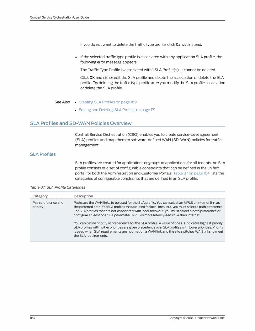
If you do not want to delete the traffic type profile, click Cancel instead.
4. If the selected traffic type profile is associated with any application SLA profile, the
following error message appears:
The Traffic Type Profile is associated with 1 SLA Profile(s). It cannot be deleted.
ClickOK and either edit the SLA profile and delete the association or delete the SLA
profile. Try deleting the traffic type profile after youmodify the SLAprofile association
or delete the SLA profile.
See Also Creating SLA Profiles on page 169•
• Editing and Deleting SLA Profiles on page 171
SLA Profiles and SD-WANPolicies Overview
Contrail Service Orchestration (CSO) enables you to create service-level agreement
(SLA) profiles andmap them to software-definedWAN (SD-WAN) policies for traffic
management.
SLA Profiles
SLA profiles are created for applications or groups of applications for all tenants. An SLA
profile consists of a set of configurable constraints that can be defined in the unified
portal for both the Administration and Customer Portals. Table 87 on page 164 lists the
categories of configurable constraints that are defined in an SLA profile.
Table 87: SLA Profile Categories
DescriptionCategory
Paths are theWAN links to be used for the SLA profile. You can select an MPLS or Internet link asthepreferredpath. ForSLAprofiles thatareused for localbreakout, youmust selectapathpreference.For SLA profiles that are not associated with local breakout, youmust select a path preference orconfigure at least one SLA parameter. MPLS is more latency-sensitive than Internet.
You can define priority or precedence for the SLA profile. A value of one (1) indicates highest priority.SLAprofileswith higher priorities are givenprecedenceover SLAprofileswith lower priorities. Priorityis used when SLA requirements are not met on aWAN link and the site switchesWAN links tomeetthe SLA requirements.
Path preference andpriority
Copyright © 2018, Juniper Networks, Inc.164
Contrail Service Orchestration User Guide
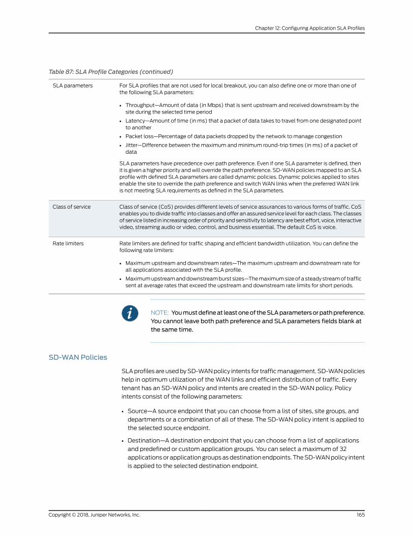
Table 87: SLA Profile Categories (continued)
For SLA profiles that are not used for local breakout, you can also define one or more than one ofthe following SLA parameters:
• Throughput—Amount of data (in Mbps) that is sent upstream and received downstream by thesite during the selected time period
• Latency—Amount of time (inms) that a packet of data takes to travel from one designated pointto another
• Packet loss—Percentage of data packets dropped by the network to manage congestion
• Jitter—Difference between themaximum andminimum round-trip times (in ms) of a packet ofdata
SLA parameters have precedence over path preference. Even if one SLA parameter is defined, thenit is given a higher priority andwill override the path preference. SD-WANpoliciesmapped to anSLAprofile with defined SLA parameters are called dynamic policies. Dynamic policies applied to sitesenable the site to override the path preference and switchWAN links when the preferredWAN linkis not meeting SLA requirements as defined in the SLA parameters.
SLA parameters
Class of service (CoS) provides different levels of service assurances to various forms of traffic. CoSenables you todivide traffic into classes andoffer an assured service level for each class. The classesof service listed in increasingorder of priority andsensitivity to latencyarebest effort, voice, interactivevideo, streaming audio or video, control, and business essential. The default CoS is voice.
Class of service
Rate limiters are defined for traffic shaping and efficient bandwidth utilization. You can define thefollowing rate limiters:
• Maximum upstream and downstream rates—Themaximum upstream and downstream rate forall applications associated with the SLA profile.
• Maximumupstreamanddownstreamburst sizes—Themaximumsizeofa steadystreamof trafficsent at average rates that exceed the upstream and downstream rate limits for short periods.
Rate limiters
NOTE: Youmustdefineat leastoneof theSLAparametersorpathpreference.You cannot leave both path preference and SLA parameters fields blank atthe same time.
SD-WANPolicies
SLAprofilesareusedbySD-WANpolicy intents for trafficmanagement. SD-WANpolicies
help in optimum utilization of theWAN links and efficient distribution of traffic. Every
tenant has an SD-WAN policy and intents are created in the SD-WAN policy. Policy
intents consist of the following parameters:
• Source—A source endpoint that you can choose from a list of sites, site groups, and
departments or a combination of all of these. The SD-WAN policy intent is applied to
the selected source endpoint.
• Destination—A destination endpoint that you can choose from a list of applications
and predefined or custom application groups. You can select a maximum of 32
applicationsorapplicationgroupsasdestinationendpoints. TheSD-WANpolicy intent
is applied to the selected destination endpoint.
165Copyright © 2018, Juniper Networks, Inc.
Chapter 12: Configuring Application SLA Profiles
• SLA profile—An SLA profile that has the required constraints you want to apply to the
policy intent.
• Intent name—A unique name for the SD-WAN policy intent.
SD-WAN supports advanced policy-based routing (APBR). APBR enables you to
dynamically define the routing behavior of the SD-WAN network based on applications.
Dynamic application-based routing makes it possible to define policies and to switch
WAN links on the fly based on the application's defined SLA parameters. The APBR
mechanism classifies sessions based on applications and application signatures and
uses policy intents to identify the best possible route for the application. When the best
possible route does not meet the application's defined SLA requirements, the SD-WAN
network finds the next best possible route to meet SLA requirements.
For example, consider an application in a site. If you want the application group to use
custom throughput, latency, or jitter, you can create an SLA profile with these custom
values. You can then create an intent and configure the intent with the application and
apply the custom SLA profile. When the intent is deployed, CSO determines the best
suitedWAN link to route traffic based in the application. If theWAN link fails to meet
SLA requirements in runtime, the SD-WAN network switchesWAN links to the next best
suited path.
On the basis of the configured SLA profile constraints, you can categorize SD-WAN
policies into two types:
• Static policy—If only the path preference is defined and none of the SLA parametersare defined in the SLA profile, then the policy is called a static policy. In static policies,
if the definedWAN link under path preference is unable tomeet the SLA requirements,
link switching cannot occur andSLAperformancedeteriorates. The fullmesh topology
supports only static policies. Also, only static policies can be applied on links that have
local breakout enabled.
• Dynamic policy—If one or more SLA parameters in the SLA profile are defined, thenthe policy is called a dynamic policy.
Indynamicpolicies, becauseSLAparametersoverride thepathpreference, theSD-WAN
network chooses the best possibleWAN link for traffic management. When an intent
is deployed on a site, if theWAN link chosen by the SD-WAN network does not meet
theSLA requirementsand thenetworkperformancedeteriorates, then thesite switches
WAN links tomeet theSLA requirements. The link switching is recordedas anSD-WAN
event and displayed in the SD-WAN Events page in the customer portal and the
Tenant_name SLA Performance pages in the administration and customer portals.
Link switching occurs only when the SD-WAN policy is dynamic because SLA
parameters override the path preference and the site is able to switchWAN links.
RelatedDocumentation
About the Application SLA Profiles Page on page 168•
• Local Breakout Overview on page 167
Copyright © 2018, Juniper Networks, Inc.166
Contrail Service Orchestration User Guide
Local Breakout Overview
The localbreakout featureenablesContrail ServiceOrchestration (CSO) to route Internet
traffic directly from a site in a software-definedWAN (SD-WAN) implementation. In the
fullmesh topology, local breakout is supportedon thebranch sites. In thehub-and-spoke
topology, local breakout is supported on the on-premise hub site and the spoke site. If
local breakout is not enabled on the spoke site, then Internet traffic is routed from the
hub site if local breakout is enabled on the hub site. Local breakout is not supported on
cloud hub sites.
When creating sites, you need to enable local breakout and configure theWAN links that
are used for local breakout traffic on the site. You also need to specify whether theWAN
links are used exclusively for local breakout traffic or for both local breakout and
non-Internet traffic. If a specific WAN link is used exclusively for local breakout, then
overlay tunnels for thatWAN link are not created. Enabling aWAN link to be used
exclusively for local breakout traffic reduces the number of overlay tunnels created
between spoke and hub sites, thereby conserving bandwidth.
You can create a source Network Address Translation (NAT) rule while enabling local
breakout on a spoke site. The source NAT rule is interface-based and is implicitly defined
and applied to the site. This automatically created source NAT rule is not visible on the
NAT Policies page. The automatically created source NAT rule has the least priority
among rules and can be overridden by a user-created NAT policy. The automatically
created source NAT rule can be enabled and disabled only from the Configuring a Site
page. For an on-premise hub site, the option for automatic creation of source NAT rule
is not available on the Configuring a Site page, and you need to create a source NAT rule.
YoucanenableSLAprofiles tobeassociatedwith local breakoutandmap theSLAprofile
to static SD-WAN policies. For SLA profiles that are used for local breakout, youmust
select a path preference. Static SD-WAN policies are used to route the traffic of the
applications defined in the static policies by using the preferred path in the attachedSLA
profile.
Applications are classified into the following categories:
• Cacheable applications—Cacheable applications are applications groups that are
stored in the application cache when they are recognized by the device. After they are
stored in the application cache, subsequent sessions are routed directly through the
correct WAN link. Only cacheable applications and application groups are supported
during the creation of local breakout-specific static SD-WAN policies.
• Non-cacheable applications—Non-cacheable applications are not stored in the
application cache and all sessions are first routed through the default path, and then
routed to the correct WAN link based on the SD-WAN policy. Non-cacheable
applications cannot be used for local breakout-specific static SD-WAN policies.
RelatedDocumentation
SLA Profiles and SD-WAN Policies Overview on page 437•
• Creating On-Premise Spoke Sites for SD-WAN Deployment on page 549
167Copyright © 2018, Juniper Networks, Inc.
Chapter 12: Configuring Application SLA Profiles
• Configuring a Single Site on page 567
• Creating SLA Profiles on page 447
About the Application SLA Profiles Page
To access this page, select Configuration > Application SLAProfiles in the Administration
Portal.
You can use the Application SLA Profiles page to view information about service-level
agreement (SLA) profiles for all tenants.
Tasks You Can Perform
You can perform the following tasks from this page:
• View details of SLA profiles for all tenants.
• Create an SLA profile for a tenant. See “Creating SLA Profiles” on page 169.
• Edit or delete an SLA profile. See “Editing and Deleting SLA Profiles” on page 171.
• Show or hide columns that contain information about SLA profiles. See “Sorting
Objects” on page 15.
• Search for SLA profiles using keywords. Click the search icon. Enter partial text or full
text of the keyword in the search bar and press Enter. The search results are displayed.
Field Descriptions
Table88onpage 168 shows thedescriptions of the fields on theApplicationSLAProfiles
page.
Table 88: Fields on the Application SLA Profiles Page
DescriptionField
Displays the SLA profile priority.Priority
Displays the SLA profile name.Name
Displays the traffic type profile associated with the SLA profile.Traffic Type Profile
Displays whether there is a preferred path for the SLA profile.Path Preference
Shows whether failover is enabled for the SLA profile.Failover
Displays whether local breakout is enabled on the SLA profile.Local Breakout
Displays the target throughput for the SLA profile.Throughput Target
Displays the target latency for the SLA profile.Latency Target
Copyright © 2018, Juniper Networks, Inc.168
Contrail Service Orchestration User Guide
Table 88: Fields on the Application SLA Profiles Page (continued)
DescriptionField
Displays the target packet loss for the SLA profile.Packet Loss Target
Displays the target jitter for the SLA profile.Jitter Target
Displays whether the profile requires the SLA probe to match all SLA criteria (All)or not (Any) .
SLA Probe Match
Displays the name of the user that created the SLA profile.Created by
RelatedDocumentation
SLA Profiles and SD-WAN Policies Overview on page 164•
• Local Breakout Overview on page 167
• Creating SLA Profiles on page 169
• Editing and Deleting SLA Profiles on page 171
Creating SLA Profiles
You can use the Create SLA Profile page to create a new service-level agreement (SLA)
profile, configure target metrics, and associate tenants with the SLA profile.
To add an SLA profile to a tenant:
1. Click the add icon (+) on the Configuration > Application SLA Profiles page in the
Administration Portal.
The Create SLA Profile page appears.
2. Enter the SLA profile information according to the guidelines provided in
Table 89 on page 169.
3. ClickOK to create the SLA profile. The Application SLA Profile page appears with the
new SLA profile information.
Alternatively, if you want to discard your updates, click Cancel instead.
Table 89: Fields on the Create SLA Profile page
GuidelinesField
General
Enter a name for the SLA profile.
Can be a unique string of not more than 15 characters that contains alphanumeric charactersand hyphen (-).
Name
169Copyright © 2018, Juniper Networks, Inc.
Chapter 12: Configuring Application SLA Profiles
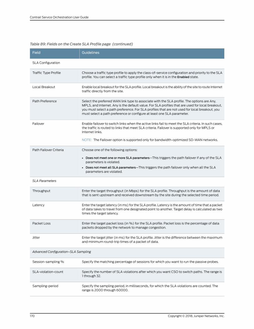
Table 89: Fields on the Create SLA Profile page (continued)
GuidelinesField
SLA Configuration
Choose a traffic type profile to apply the class-of-service configuration and priority to the SLAprofile. You can select a traffic type profile only when it is in the Enabled state.
Traffic Type Profile
Enable local breakout for theSLAprofile. Local breakout is theability of the site to route Internettraffic directly from the site.
Local Breakout
Select the preferredWAN link type to associate with the SLA profile. The options are Any,MPLS, and Internet. Any is the default value. For SLA profiles that are used for local breakout,youmust select a path preference. For SLA profiles that are not used for local breakout, youmust select a path preference or configure at least one SLA parameter.
Path Preference
Enable failover to switch links when the active links fail tomeet the SLA criteria. In such cases,the traffic is routed to links that meet SLA criteria. Failover is supported only for MPLS orInternet links.
NOTE: The Failover option is supported only for bandwidth-optimized SD-WAN networks.
Failover
Choose one of the following options:
• Does notmeet one ormore SLA parameters—This triggers the path failover if any of the SLAparameters is violated.
• Does notmeet all SLA parameters—This triggers the path failover only when all the SLAparameters are violated.
Path Failover Criteria
SLA Parameters
Enter the target throughput (in Mbps) for the SLA profile. Throughput is the amount of datathat is sent upstream and received downstream by the site during the selected time period.
Throughput
Enter the target latency (inms) for theSLAprofile. Latency is the amount of time that a packetof data takes to travel from one designated point to another. Target delay is calculated as twotimes the target latency.
Latency
Enter the target packet loss (in%) for the SLA profile. Packet loss is the percentage of datapackets dropped by the network to manage congestion.
Packet Loss
Enter the target jitter (inms) for the SLA profile. Jitter is the difference between themaximumandminimum round-trip times of a packet of data.
Jitter
Advanced Configuration–SLA Sampling
Specify the matching percentage of sessions for which you want to run the passive probes.Session-sampling%
Specify the number of SLA violations after which you want CSO to switch paths. The range is1 through 32.
SLA-violation-count
Specify the sampling period, in milliseconds, for which the SLA violations are counted. Therange is 2000 through 60000.
Sampling-period
Copyright © 2018, Juniper Networks, Inc.170
Contrail Service Orchestration User Guide
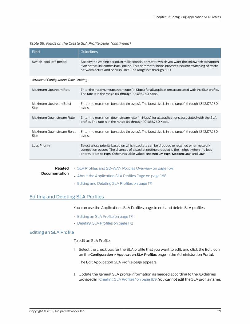
Table 89: Fields on the Create SLA Profile page (continued)
GuidelinesField
Specify thewaiting period, inmilliseconds, only afterwhich youwant the link switch to happenif an active link comes back online. This parameter helps prevent frequent switching of trafficbetween active and backup links. The range is 5 through 300.
Switch-cool-off-period
Advanced Configuration-Rate Limiting
Enter themaximumupstreamrate (inKbps) for all applicationsassociatedwith theSLAprofile.The rate is in the range 64 through 10,485,760 Kbps.
MaximumUpstream Rate
Enter the maximum burst size (in bytes). The burst size is in the range 1 through 1,342,177,280bytes.
MaximumUpstream BurstSize
Enter the maximum downstream rate (in Kbps) for all applications associated with the SLAprofile. The rate is in the range 64 through 10,485,760 Kbps.
MaximumDownstream Rate
Enter the maximum burst size (in bytes). The burst size is in the range 1 through 1,342,177,280bytes.
MaximumDownstream BurstSize
Select a loss priority based on which packets can be dropped or retained when networkcongestion occurs. The chances of a packet getting dropped is the highest when the losspriority is set to High. Other available values areMediumHigh,Medium Low, and Low.
Loss Priority
RelatedDocumentation
SLA Profiles and SD-WAN Policies Overview on page 164•
• About the Application SLA Profiles Page on page 168
• Editing and Deleting SLA Profiles on page 171
Editing and Deleting SLA Profiles
You can use the Applications SLA Profiles page to edit and delete SLA profiles.
• Editing an SLA Profile on page 171
• Deleting SLA Profiles on page 172
Editing an SLA Profile
To edit an SLA Profile:
1. Select the check box for the SLA profile that you want to edit, and click the Edit icon
on the Configuration > Application SLA Profiles page in the Administration Portal.
The Edit Application SLA Profile page appears.
2. Update the general SLA profile information as needed according to the guidelines
provided in “CreatingSLAProfiles” onpage 169. You cannot edit theSLAprofile name.
171Copyright © 2018, Juniper Networks, Inc.
Chapter 12: Configuring Application SLA Profiles
3. Click Next.
The Configuration tab appears.
4. Update the configuration parameters as needed according to the guidelines provided
in “Creating SLA Profiles” on page 169.
5. ClickOK to save the updated SLA profile configuration.
TheSLAprofile information that you updatedappears on theApplicationSLAProfiles
page.
Deleting SLA Profiles
You can delete the SLA profile if it is no longer needed. To delete an SLA profile:
1. Select the check box for the SLA profile that you want to delete and click the delete
icon (Χ) on the Configuration > Application SLA Profiles page in the AdministrationPortal. You can also select multiple SLA profiles.
A page requesting confirmation for the deletion appears.
2. Click Yes to confirm that you want to delete the SLA profile.
The SLA profile is deleted.
RelatedDocumentation
• SLA Profiles and SD-WAN Policies Overview on page 164
• About the Application SLA Profiles Page on page 168
• Creating SLA Profiles on page 169
Copyright © 2018, Juniper Networks, Inc.172
Contrail Service Orchestration User Guide
CHAPTER 13
Configuring Application Signatures
• Application Signatures Overview on page 173
• About the Application Signatures Page on page 174
• Creating Application Signature Groups on page 175
• Editing, Cloning, and Deleting Application Signature Groups on page 176
Application Signatures Overview
JuniperNetworks regularlyupdates thepredefinedapplicationsignaturedatabase,making
it available to subscribers on the Juniper Networks website. This database includes
signaturedefinitionsof knownapplicationobjects thatcanbeused to identifyapplications
for tracking, firewall policies, and quality-of-service prioritization.
Use the Application Signatures page to get an overall, high-level view of your application
signature settings. You can filter and sort this information to get a better understanding
of what you want to configure.
RelatedDocumentation
About the Application Signatures Page on page 174•
• Creating Application Signature Groups on page 175
• Editing, Cloning, and Deleting Application Signature Groups on page 176
173Copyright © 2018, Juniper Networks, Inc.
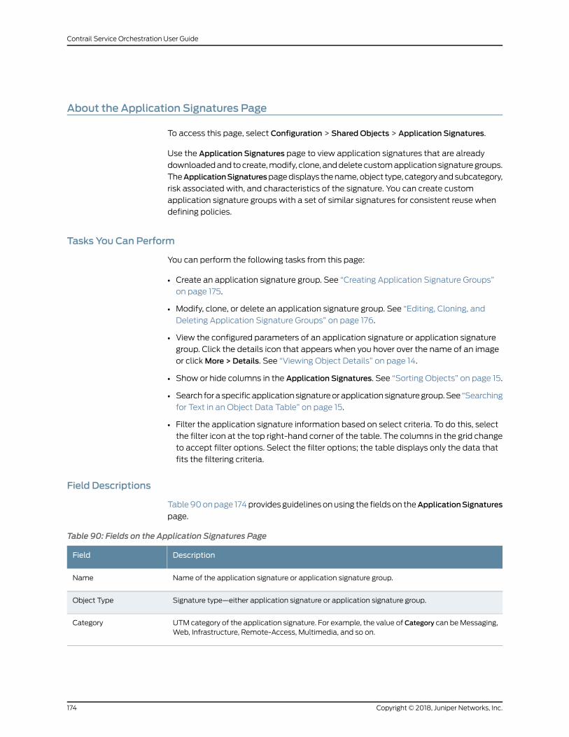
About the Application Signatures Page
To access this page, select Configuration > Shared Objects > Application Signatures.
Use the Application Signatures page to view application signatures that are already
downloadedand tocreate,modify, clone, anddeletecustomapplicationsignaturegroups.
TheApplicationSignaturespagedisplays thename,object type, categoryandsubcategory,
risk associated with, and characteristics of the signature. You can create custom
application signature groups with a set of similar signatures for consistent reuse when
defining policies.
Tasks You Can Perform
You can perform the following tasks from this page:
• Create an application signature group. See “Creating Application Signature Groups”
on page 175.
• Modify, clone, or delete an application signature group. See “Editing, Cloning, and
Deleting Application Signature Groups” on page 176.
• View the configured parameters of an application signature or application signature
group. Click the details icon that appears when you hover over the name of an image
or clickMore > Details. See “Viewing Object Details” on page 14.
• Show or hide columns in the Application Signatures. See “Sorting Objects” on page 15.
• Search foraspecificapplicationsignatureorapplicationsignaturegroup.See “Searching
for Text in an Object Data Table” on page 15.
• Filter the application signature information based on select criteria. To do this, select
the filter icon at the top right-hand corner of the table. The columns in the grid change
to accept filter options. Select the filter options; the table displays only the data that
fits the filtering criteria.
Field Descriptions
Table90onpage 174providesguidelinesonusing the fieldson theApplicationSignatures
page.
Table 90: Fields on the Application Signatures Page
DescriptionField
Name of the application signature or application signature group.Name
Signature type—either application signature or application signature group.Object Type
UTM category of the application signature. For example, the value of Category can beMessaging,Web, Infrastructure, Remote-Access, Multimedia, and so on.
Category
Copyright © 2018, Juniper Networks, Inc.174
Contrail Service Orchestration User Guide
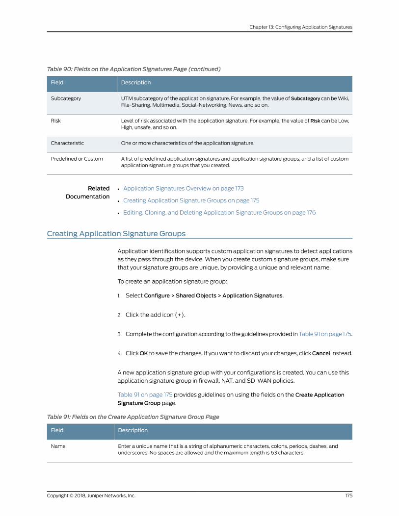
Table 90: Fields on the Application Signatures Page (continued)
DescriptionField
UTMsubcategory of the application signature. For example, the value ofSubcategory can beWiki,File-Sharing, Multimedia, Social-Networking, News, and so on.
Subcategory
Level of risk associated with the application signature. For example, the value of Risk can be Low,High, unsafe, and so on.
Risk
One or more characteristics of the application signature.Characteristic
A list of predefined application signatures and application signature groups, and a list of customapplication signature groups that you created.
Predefined or Custom
RelatedDocumentation
Application Signatures Overview on page 173•
• Creating Application Signature Groups on page 175
• Editing, Cloning, and Deleting Application Signature Groups on page 176
Creating Application Signature Groups
Application identification supports customapplication signatures to detect applications
as they pass through the device. When you create custom signature groups, make sure
that your signature groups are unique, by providing a unique and relevant name.
To create an application signature group:
1. Select Configure > Shared Objects > Application Signatures.
2. Click the add icon (+).
3. Complete theconfigurationaccording to theguidelinesprovided inTable91onpage 175.
4. ClickOK to save the changes. If youwant todiscard your changes, clickCancel instead.
A new application signature group with your configurations is created. You can use this
application signature group in firewall, NAT, and SD-WAN policies.
Table 91 on page 175 provides guidelines on using the fields on the Create Application
Signature Group page.
Table 91: Fields on the Create Application Signature Group Page
DescriptionField
Enter a unique name that is a string of alphanumeric characters, colons, periods, dashes, andunderscores. No spaces are allowed and themaximum length is 63 characters.
Name
175Copyright © 2018, Juniper Networks, Inc.
Chapter 13: Configuring Application Signatures
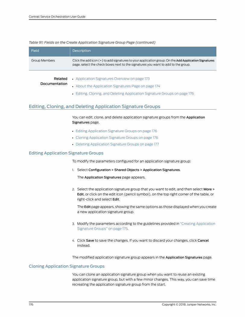
Table 91: Fields on the Create Application Signature Group Page (continued)
DescriptionField
Click theadd icon(+) toaddsignatures toyourapplicationgroup.On theAddApplicationSignaturespage, select the check boxes next to the signatures you want to add to the group.
Group Members
RelatedDocumentation
Application Signatures Overview on page 173•
• About the Application Signatures Page on page 174
• Editing, Cloning, and Deleting Application Signature Groups on page 176
Editing, Cloning, and Deleting Application Signature Groups
You can edit, clone, and delete application signature groups from the Application
Signatures page.
• Editing Application Signature Groups on page 176
• Cloning Application Signature Groups on page 176
• Deleting Application Signature Groups on page 177
Editing Application Signature Groups
Tomodify the parameters configured for an application signature group:
1. Select Configuration > Shared Objects > Application Signatures.
The Application Signatures page appears.
2. Select the application signature group that you want to edit, and then selectMore >
Edit, or click on the edit icon (pencil symbol), on the top right corner of the table, or
right-click and select Edit.
TheEditpageappears, showing the sameoptionsas thosedisplayedwhen youcreate
a new application signature group.
3. Modify the parameters according to the guidelines provided in “Creating Application
Signature Groups” on page 175.
4. Click Save to save the changes. If you want to discard your changes, click Cancel
instead.
Themodified application signature group appears in the Application Signatures page.
Cloning Application Signature Groups
You can clone an application signature group when you want to reuse an existing
application signature group, but with a fewminor changes. This way, you can save time
recreating the application signature group from the start.
Copyright © 2018, Juniper Networks, Inc.176
Contrail Service Orchestration User Guide
To clone an application signature group:
1. Select Configuration > Shared Objects > Application Signatures.
The Application Signatures page appears.
2. Right-click the application signature group that you want to clone and then select
Clone, or selectMore > Clone.
The Clone page appears with editable fields.
3. ClickOK to save the changes. If youwant todiscard your changes, clickCancel instead.
The cloned application signature group is displayed on the Application Signatures page.
Deleting Application Signature Groups
To delete an application signature group:
1. Select Configuration > Shared Objects > Application Signatures.
The Application Signatures page appears.
2. Select the application signature group you want to delete and then click the delete
icon (X).
An alert message appears, verifying that you want to delete the selected item.
3. Click Yes to delete the selected application signature group. If you do not want to
delete, click Cancel instead.
RelatedDocumentation
• Application Signatures Overview on page 173
• About the Application Signatures Page on page 174
• Creating Application Signature Groups on page 175
177Copyright © 2018, Juniper Networks, Inc.
Chapter 13: Configuring Application Signatures

Copyright © 2018, Juniper Networks, Inc.178
Contrail Service Orchestration User Guide
CHAPTER 14
Managing Tenants
• Tenant Overview on page 179
• Full Mesh Topology Overview on page 179
• About the Tenants Page on page 181
• Adding a Single Tenant on page 183
• Editing Tenant Information on page 187
• Importing Data for Multiple Tenants on page 188
• Allocating Network Services to a Tenant on page 192
• Viewing the History of Imported Tenant Data on page 193
• Viewing the History of Deleted Tenant Data on page 194
Tenant Overview
Atenant inaCloudCPEsolution representsacustomerwhoaccessesvirtualizednetwork
functions (VNFs) in a service provider’s cloud through a Layer 3 VPN. You assign
administrative users and sites to customers in the Administration Portal to represent the
staff in the customer’s organization and the geographical locations in the customer’s
network. You also use Administration Portal to allocate network service profiles to
customers.
RelatedDocumentation
Administration Portal Overview on page 4•
• About the Tenants Page on page 181
• Editing Tenant Information on page 187
• Adding a Single Tenant on page 183
• Importing Data for Multiple Tenants on page 188
Full Mesh Topology Overview
Cloud CPE Solution supports the full mesh topology on tenants in a software-defined
WAN (SD-WAN) implementation. In a full mesh topology, all sites of a tenant are
connected to one another. The topology is selected when the tenant is created and
cannot bemodified later. A tenant supports only one full mesh network because all sites
179Copyright © 2018, Juniper Networks, Inc.
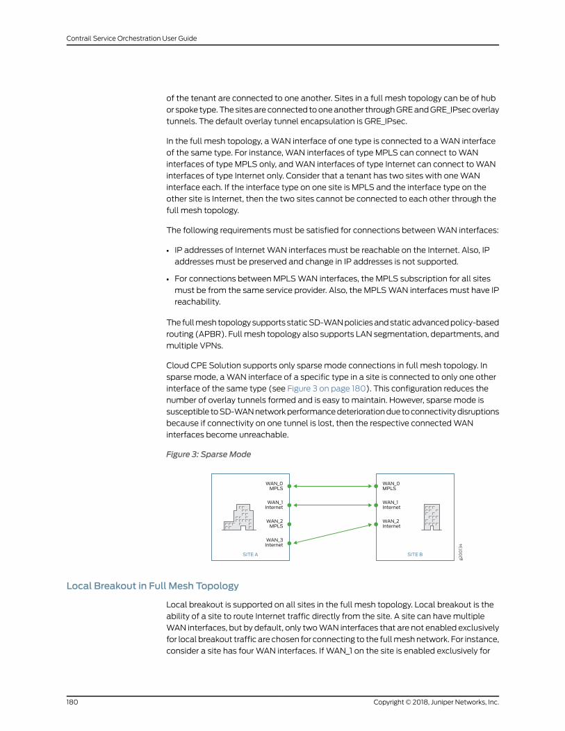
of the tenant are connected to one another. Sites in a full mesh topology can be of hub
or spoke type.Thesitesareconnected tooneanother throughGREandGRE_IPsecoverlay
tunnels. The default overlay tunnel encapsulation is GRE_IPsec.
In the full mesh topology, aWAN interface of one type is connected to aWAN interface
of the same type. For instance, WAN interfaces of type MPLS can connect toWAN
interfaces of type MPLS only, andWAN interfaces of type Internet can connect toWAN
interfaces of type Internet only. Consider that a tenant has two sites with oneWAN
interface each. If the interface type on one site is MPLS and the interface type on the
other site is Internet, then the two sites cannot be connected to each other through the
full mesh topology.
The following requirements must be satisfied for connections betweenWAN interfaces:
• IP addresses of InternetWAN interfaces must be reachable on the Internet. Also, IP
addresses must be preserved and change in IP addresses is not supported.
• For connections between MPLSWAN interfaces, the MPLS subscription for all sites
must be from the same service provider. Also, the MPLSWAN interfacesmust have IP
reachability.
The fullmeshtopologysupportsstaticSD-WANpoliciesandstaticadvancedpolicy-based
routing (APBR). Fullmesh topology also supports LAN segmentation, departments, and
multiple VPNs.
Cloud CPE Solution supports only sparse mode connections in full mesh topology. In
sparse mode, aWAN interface of a specific type in a site is connected to only one other
interface of the same type (see Figure 3 on page 180). This configuration reduces the
number of overlay tunnels formed and is easy to maintain. However, sparse mode is
susceptible toSD-WANnetworkperformancedeteriorationduetoconnectivitydisruptions
because if connectivity on one tunnel is lost, then the respective connectedWAN
interfaces become unreachable.
Figure 3: Sparse Modeg200134
WAN_0MPLS
WAN_2MPLS
WAN_3Internet
WAN_1Internet
SITE A
WAN_0MPLS
WAN_2Internet
WAN_1Internet
SITE B
Local Breakout in Full Mesh Topology
Local breakout is supported on all sites in the full mesh topology. Local breakout is the
ability of a site to route Internet traffic directly from the site. A site can havemultiple
WAN interfaces, but by default, only twoWAN interfaces that are not enabled exclusively
for local breakout traffic are chosen for connecting to the fullmeshnetwork. For instance,
consider a site has four WAN interfaces. If WAN_1 on the site is enabled exclusively for
Copyright © 2018, Juniper Networks, Inc.180
Contrail Service Orchestration User Guide
local breakout traffic, then onlyWAN_0 andWAN_2 are chosen for forming a full mesh.
WAN interfaces that are enabled exclusively for local breakout traffic cannot be used
for non-Internet traffic and this makes thoseWAN interfaces essentially unusable in the
full mesh topology. For WAN interfaces that are chosen to connect to the full mesh
network, you do not need to provide overlay tunnel informationwhile configuring the site.
The overlay tunnel information is computed automatically.
RelatedDocumentation
SLA Profiles and SD-WAN Policies Overview on page 164•
• About the Tenants Page on page 181
• Local Breakout Overview on page 537
About the Tenants Page
To access this page, click Tenants.
You can use the Tenants page to create a tenant, import tenants and other objects
associated with tenants, such as administrative users and sites, and view the history of
imported tenant data and deleted tenant data. See “Tenant Overview” on page 179.
Before You Begin
Create all the resources required for the network point of presence (POP).
Tasks You Can Perform
You can perform the following tasks from this page:
• Quickly view important data about the tenants in the widgets that appear at the top
of the page. For information about the widgets, see Table 92 on page 182.
• View details about a tenant. Click the details icon for the tenant. See “Viewing Object
Details” on page 14.
• Add a single tenant. See “Adding a Single Tenant” on page 183.
• Edit tenant information. See “Editing Tenant Information” on page 187.
• Import multiple tenants. See “Importing Data for Multiple Tenants” on page 188.
• Assign Network Services. See “Allocating Network Services to a Tenant” on page 192.
• View tenant import history. See “Viewing the History of Imported Tenant Data” on
page 193.
• Viewtenantdeletehistory.See “Viewing theHistoryofDeletedTenantData”onpage 194.
Field Descriptions
Table 92 on page 182 shows the description of the widget that appears at the top of the
Tenants page.
181Copyright © 2018, Juniper Networks, Inc.
Chapter 14: Managing Tenants
Table 92:Widget on the Tenants Page
DescriptionWidget
View the numbers of tenants and their types.Tenants by Topology
View the tenants with alerts defined on them.Tenants with Alerts
Table 93 on page 182 provides guidelines on using the fields on the Tenants page.
Table 93: Fields on the Tenants Page
DescriptionField
View the name of the tenant.
Click the name to view full information about a tenant.
Name
View the type of tenant. The tenant type limits the number of service instances for a tenant.The following options are available:
• Small
• Medium
• Large
• Default
Type
View the topology of the tenant.
Example:
• Standalone
• Hub and Spoke
Topology
View the deployment scenario of the tenant.
Example:
• HYBRIDWAN
• SDWAN
Plan
View the total number of sites that are available for the tenant.Sites
View the number of services that are assigned to the tenant.Assigned Services
View the number of services that have been deployed by the administrator on a connectionin the network.
Activated Service Instances
View the administrative user for the tenant.Administrator
View the date and time when the tenant was last logged in.Last Login
RelatedDocumentation
Allocating a Service to Tenants on page 139•
• Importing Data for Multiple Tenants on page 188
Copyright © 2018, Juniper Networks, Inc.182
Contrail Service Orchestration User Guide
Adding a Single Tenant
You can use the Add Tenant page to add tenant data and other objects associated with
a tenant, such as administrative user, network details, deployment scenario, service
profiles, and custom properties. A single tenant supports centralized deployment,
distributed deployment, and hybrid (both centralized and distributed) deployment
scenarios.
Begin by creating all the resources required for the network point of presence (POP).
The information listed on the Tenants page changes depending on the authentication
mode configured:
• LocalAuthentication—You can add the administrative user information as the first step
from the Tenants page.
• Authentication and Authorization with SSO Server—The Admin User information is not
displayed on the Tenants page because users are not created in CSO and they are
managed in the SAML identity provider. In addition, users are dynamically authorized
to the CSO role based on themapping rules configured in the SAML authentication.
• Authentication with SSO Server—When you create the administrative user, the login
page does not require you to configure a password because the user is created in the
SSOwithout the password and you can enter only the username.
To add a tenant:
1. Select Tenants > All Tenants > +.
The Add Tenant page appears.
2. Update the tenant information.Complete theconfigurationaccording to theguidelines
provided in Table 94 on page 183.
3. ClickOK. If you want to discard your changes, click Cancel instead.
If you clickOK, the tenant that you configured appears on the Tenants page.
4. If you use the tenant for a hybridWAN centralized deployment, access Contrail and
add the following rule to the default security group in the Contrail project.
Ingress IPv4 network 0.0.0.0/0 protocol any ports any
This rule allows the network to accept traffic from all subnets.
Table 94: Fields on the Add Tenant Page
DescriptionField
Tenant Info
183Copyright © 2018, Juniper Networks, Inc.
Chapter 14: Managing Tenants
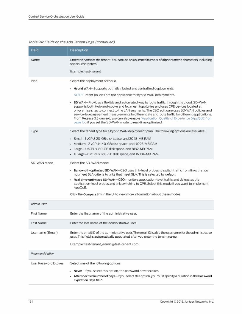
Table 94: Fields on the Add Tenant Page (continued)
DescriptionField
Enter thenameof the tenant.Youcanuseanunlimitednumberofalphanumeric characters, includingspecial characters.
Example: test-tenant
Name
Select the deployment scenario.
• HybridWAN—Supports both distributed and centralized deployments.
NOTE: Intent policies are not applicable for hybridWAN deployments.
• SDWAN—Provides a flexible and automated way to route traffic through the cloud. SD-WANsupports both Hub-and-spoke and full mesh topologies and uses CPE devices located aton-premise sites to connect to the LAN segments. The CSO software uses SD-WAN policies andservice-level agreementmeasurements todifferentiate and route traffic for different applications.From Release 3.3 onward, you can also enable “Application Quality of Experience (AppQoE)” onpage 155 if you set the SD-WANmode to real-time optimized.
Plan
Select the tenant type for a hybridWAN deployment plan. The following options are available:
• Small—1 vCPU, 20-GB disk space, and 2048-MB RAM
• Medium—2 vCPUs, 40-GB disk space, and 4096-MB RAM
• Large—4 vCPUs, 80-GB disk space, and 8192-MB RAM
• X Large—8 vCPUs, 160-GB disk space, and 16384-MB RAM
Type
Select the SD-WANmode:
• Bandwidth-optimized SD-WAN—CSO uses link-level probes to switch traffic from links that donot meet SLA criteria to links that meet SLA. This is selected by default.
• Real time-optimized SD-WAN—CSOmonitors application-level traffic and delegates theapplication-level probes and link switching to CPE. Select this mode if you want to implementAppQoE.
Click the Compare link in the UI to viewmore information about these modes.
SD-WANMode
Admin user
Enter the first name of the administrative user.First Name
Enter the last name of the administrative user.Last Name
Enter the email IDof theadministrative user. Theemail ID is also theusername for theadministrativeuser. This field is automatically populated after you enter the tenant name.
Example: [email protected]
Username (Email)
Password Policy
Select one of the following options:
• Never—If you select this option, the password never expires.
• Afterspecifiednumberofdays—If youselect thisoption, youmust specifyaduration in thePasswordExpiration Days field.
User Password Expires
Copyright © 2018, Juniper Networks, Inc.184
Contrail Service Orchestration User Guide
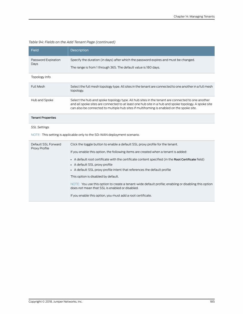
Table 94: Fields on the Add Tenant Page (continued)
DescriptionField
Specify the duration (in days) after which the password expires andmust be changed.
The range is from 1 through 365. The default value is 180 days.
Password ExpirationDays
Topology Info
Select the fullmesh topology type. All sites in the tenant are connected to one another in a fullmeshtopology.
Full Mesh
Select the hub and spoke topology type. All hub sites in the tenant are connected to one anotherand all spoke sites are connected to at least one hub site in a hub and spoke topology. A spoke sitecan also be connected to multiple hub sites if multihoming is enabled on the spoke site.
Hub and Spoke
Tenant Properties
SSL Settings
NOTE: This setting is applicable only to the SD-WAN deployment scenario.
Click the toggle button to enable a default SSL proxy profile for the tenant.
If you enable this option, the following items are created when a tenant is added:
• A default root certificate with the certificate content specified (in the Root Certificate field)
• A default SSL proxy profile
• A default SSL proxy profile intent that references the default profile
This option is disabled by default.
NOTE: You use this option to create a tenant-wide default profile; enabling or disabling this optiondoes notmean that SSL is enabled or disabled.
If you enable this option, youmust add a root certificate.
Default SSL ForwardProxy Profile
185Copyright © 2018, Juniper Networks, Inc.
Chapter 14: Managing Tenants
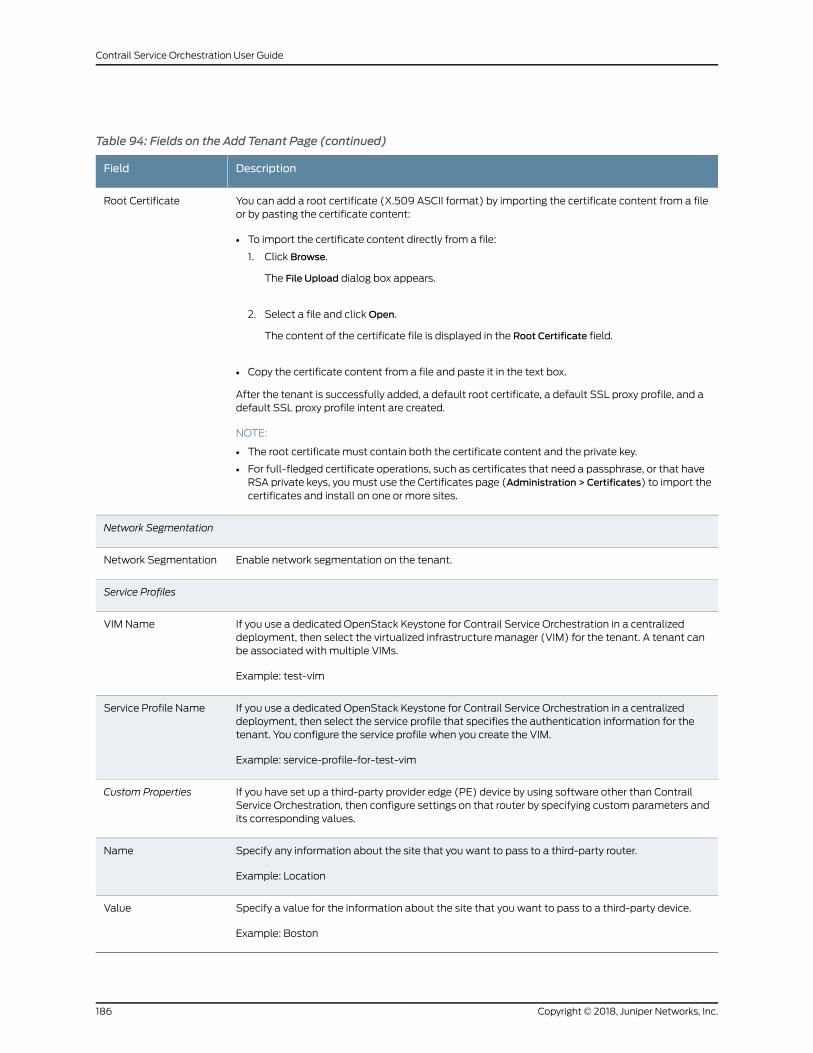
Table 94: Fields on the Add Tenant Page (continued)
DescriptionField
You can add a root certificate (X.509 ASCII format) by importing the certificate content from a fileor by pasting the certificate content:
• To import the certificate content directly from a file:
1. Click Browse.
The File Upload dialog box appears.
2. Select a file and clickOpen.
The content of the certificate file is displayed in the Root Certificate field.
• Copy the certificate content from a file and paste it in the text box.
After the tenant is successfully added, a default root certificate, a default SSL proxy profile, and adefault SSL proxy profile intent are created.
NOTE:
• The root certificate must contain both the certificate content and the private key.
• For full-fledged certificate operations, such as certificates that need a passphrase, or that haveRSA private keys, youmust use the Certificates page (Administration > Certificates) to import thecertificates and install on one or more sites.
Root Certificate
Network Segmentation
Enable network segmentation on the tenant.Network Segmentation
Service Profiles
If you use a dedicated OpenStack Keystone for Contrail Service Orchestration in a centralizeddeployment, then select the virtualized infrastructure manager (VIM) for the tenant. A tenant canbe associated with multiple VIMs.
Example: test-vim
VIM Name
If you use a dedicated OpenStack Keystone for Contrail Service Orchestration in a centralizeddeployment, then select the service profile that specifies the authentication information for thetenant. You configure the service profile when you create the VIM.
Example: service-profile-for-test-vim
Service Profile Name
If you have set up a third-party provider edge (PE) device by using software other than ContrailService Orchestration, then configure settings on that router by specifying custom parameters andits corresponding values.
Custom Properties
Specify any information about the site that you want to pass to a third-party router.
Example: Location
Name
Specify a value for the information about the site that you want to pass to a third-party device.
Example: Boston
Value
Copyright © 2018, Juniper Networks, Inc.186
Contrail Service Orchestration User Guide
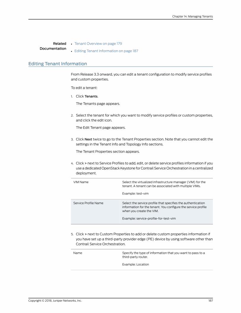
RelatedDocumentation
Tenant Overview on page 179•
• Editing Tenant Information on page 187
Editing Tenant Information
From Release 3.3 onward, you can edit a tenant configuration to modify service profiles
and custom properties.
To edit a tenant:
1. Click Tenants.
The Tenants page appears.
2. Select the tenant for which you want to modify service profiles or custom properties,
and click the edit icon.
The Edit Tenant page appears.
3. Click Next twice to go to the Tenant Properties section. Note that you cannot edit the
settings in the Tenant Info and Topology Info sections.
The Tenant Properties section appears.
4. Click > next to Service Profiles to add, edit, or delete service profiles information if you
useadedicatedOpenStackKeystone forContrail ServiceOrchestration inacentralized
deployment.
Select the virtualized infrastructure manager (VIM) for thetenant. A tenant can be associated with multiple VIMs.
Example: test-vim
VIM Name
Select the service profile that specifies the authenticationinformation for the tenant. You configure the service profilewhen you create the VIM.
Example: service-profile-for-test-vim
Service Profile Name
5. Click > next to Custom Properties to add or delete custom properties information if
you have set up a third-party provider edge (PE) device by using software other than
Contrail Service Orchestration.
Specify the type of information that you want to pass to athird-party router.
Example: Location
Name
187Copyright © 2018, Juniper Networks, Inc.
Chapter 14: Managing Tenants
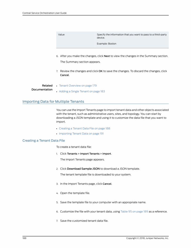
Specify the information that you want to pass to a third-partydevice.
Example: Boston
Value
6. After youmake the changes, click Next to view the changes in the Summary section.
The Summary section appears.
7. Review the changes and clickOK to save the changes. To discard the changes, click
Cancel.
RelatedDocumentation
Tenant Overview on page 179•
• Adding a Single Tenant on page 183
Importing Data for Multiple Tenants
You canuse the Import Tenants page to import tenant data andother objects associated
with the tenant, such as administrative users, sites, and topology. You can start by
downloading a JSON template and using it to customize the data file that you want to
import.
• Creating a Tenant Data File on page 188
• Importing Tenant Data on page 191
Creating a Tenant Data File
To create a tenant data file:
1. Click Tenants > Import Tenants > Import.
The Import Tenants page appears.
2. Click Download Sample JSON to download a JSON template.
The tenant template file is downloaded to your system.
3. In the Import Tenants page, click Cancel.
4. Open the template file.
5. Save the template file to your computer with an appropriate name.
6. Customize the file with your tenant data, using Table 95 on page 189 as a reference.
7. Save the customized tenant data file.
Copyright © 2018, Juniper Networks, Inc.188
Contrail Service Orchestration User Guide
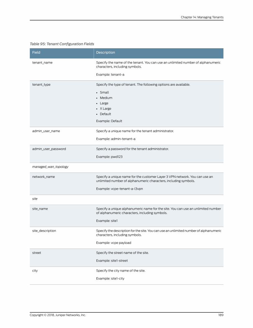
Table 95: Tenant Configuration Fields
DescriptionField
Specify the name of the tenant. You can use an unlimited number of alphanumericcharacters, including symbols.
Example: tenant-a
tenant_name
Specify the type of tenant. The following options are available.
• Small
• Medium
• Large
• X Large
• Default
Example: Default
tenant_type
Specify a unique name for the tenant administrator.
Example: admin-tenant-a
admin_user_name
Specify a password for the tenant administrator.
Example: pwd123
admin_user_password
managed_wan_topology
Specify a unique name for the customer Layer 3 VPN network. You can use anunlimited number of alphanumeric characters, including symbols.
Example: vcpe-tenant-a-l3vpn
network_name
site
Specify a unique alphanumeric name for the site. You can use an unlimited numberof alphanumeric characters, including symbols.
Example: site1
site_name
Specify thedescription for the site. Youcanuseanunlimitednumberof alphanumericcharacters, including symbols.
Example: vcpe payload
site_description
Specify the street name of the site.
Example: site1-street
street
Specify the city name of the site.
Example: site1-city
city
189Copyright © 2018, Juniper Networks, Inc.
Chapter 14: Managing Tenants
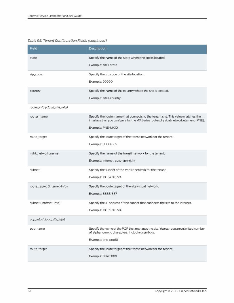
Table 95: Tenant Configuration Fields (continued)
DescriptionField
Specify the name of the state where the site is located.
Example: site1-state
state
Specify the zip code of the site location.
Example: 99990
zip_code
Specify the name of the country where the site is located.
Example: site1-country
country
router_info (cloud_site_info)
Specify the router name that connects to the tenant site. This value matches theinterface that youconfigure for theMXSeries router physical network element (PNE).
Example: PNE-MX10
router_name
Specify the route target of the transit network for the tenant.
Example: 8888:889
route_target
Specify the name of the transit network for the tenant.
Example: internet, corp-vpn-right
right_network_name
Specify the subnet of the transit network for the tenant.
Example: 10.154.0.0/24
subnet
Specify the route target of the site virtual network.
Example: 8888:887
route_target (internet-info)
Specify the IP address of the subnet that connects the site to the Internet.
Example: 10.155.0.0/24
subnet (internet-info)
pop_info (cloud_site_info)
Specify thenameof thePOPthatmanages thesite. Youcanuseanunlimitednumberof alphanumeric characters, including symbols.
Example: pne-pop10
pop_name
Specify the route target of the transit network for the tenant.
Example: 8828:889
route_target
Copyright © 2018, Juniper Networks, Inc.190
Contrail Service Orchestration User Guide
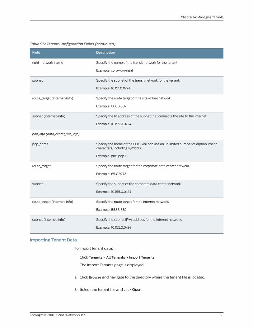
Table 95: Tenant Configuration Fields (continued)
DescriptionField
Specify the name of the transit network for the tenant.
Example: corp-vpn-right
right_network_name
Specify the subnet of the transit network for the tenant.
Example: 10.151.0.0/24
subnet
Specify the route target of the site virtual network.
Example: 8888:887
route_target (internet-info)
Specify the IP address of the subnet that connects the site to the Internet.
Example: 10.155.0.0/24
subnet (internet-info)
pop_info (data_center_site_info)
Specify the name of the POP. You can use an unlimited number of alphanumericcharacters, including symbols.
Example: pne-pop10
pop_name
Specify the route target for the corporate data center network.
Example: 65412:772
route_target
Specify the subnet of the corporate data center network.
Example: 10.155.0.0/24
subnet
Specify the route target for the Internet network.
Example: 8888:887
route_target (internet-info)
Specify the subnet IPv4 address for the Internet network.
Example: 10.155.0.0/24
subnet (internet-info)
Importing Tenant Data
To import tenant data:
1. Click Tenants > All Tenants > Import Tenants.
The Import Tenants page is displayed.
2. Click Browse and navigate to the directory where the tenant file is located.
3. Select the tenant file and clickOpen.
191Copyright © 2018, Juniper Networks, Inc.
Chapter 14: Managing Tenants
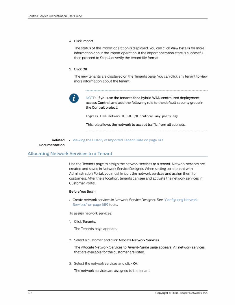
4. Click Import.
The status of the import operation is displayed. You can click View Details for more
information about the import operation. If the import operation state is successful,
then proceed to Step 4 or verify the tenant file format.
5. ClickOK.
The new tenants are displayed on the Tenants page. You can click any tenant to view
more information about the tenant.
NOTE: If you use the tenants for a hybridWAN centralized deployment,access Contrail and add the following rule to the default security group inthe Contrail project.
Ingress IPv4 network 0.0.0.0/0 protocol any ports any
This rule allows the network to accept traffic from all subnets.
RelatedDocumentation
Viewing the History of Imported Tenant Data on page 193•
Allocating Network Services to a Tenant
Use the Tenants page to assign the network services to a tenant. Network services are
created and saved in Network Service Designer. When setting up a tenant with
Administration Portal, you must import the network services and assign them to
customers. After the allocation, tenants can see and activate the network services in
Customer Portal.
Before You Begin
• Create network services in Network Service Designer. See “Configuring Network
Services” on page 689 topic.
To assign network services:
1. Click Tenants.
The Tenants page appears.
2. Select a customer and click Allocate Network Services.
The Allocate Network Services to Tenant-Name page appears. All network services
that are available for the customer are listed.
3. Select the network services and clickOk.
The network services are assigned to the tenant.
Copyright © 2018, Juniper Networks, Inc.192
Contrail Service Orchestration User Guide
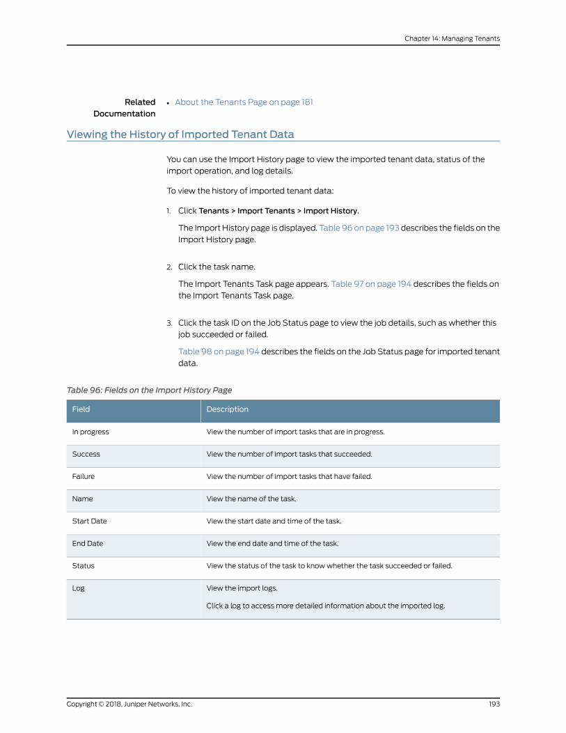
RelatedDocumentation
About the Tenants Page on page 181•
Viewing the History of Imported Tenant Data
You can use the Import History page to view the imported tenant data, status of the
import operation, and log details.
To view the history of imported tenant data:
1. Click Tenants > Import Tenants > Import History.
The Import History page is displayed. Table 96 on page 193 describes the fields on the
Import History page.
2. Click the task name.
The Import Tenants Task page appears. Table 97 on page 194 describes the fields on
the Import Tenants Task page.
3. Click the task ID on the Job Status page to view the job details, such as whether this
job succeeded or failed.
Table 98 on page 194 describes the fields on the Job Status page for imported tenant
data.
Table 96: Fields on the Import History Page
DescriptionField
View the number of import tasks that are in progress.In progress
View the number of import tasks that succeeded.Success
View the number of import tasks that have failed.Failure
View the name of the task.Name
View the start date and time of the task.Start Date
View the end date and time of the task.End Date
View the status of the task to knowwhether the task succeeded or failed.Status
View the import logs.
Click a log to access more detailed information about the imported log.
Log
193Copyright © 2018, Juniper Networks, Inc.
Chapter 14: Managing Tenants
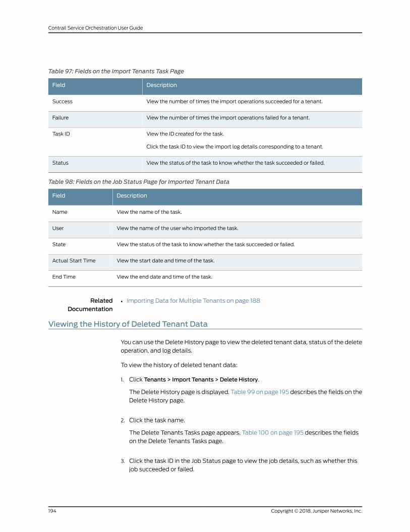
Table 97: Fields on the Import Tenants Task Page
DescriptionField
View the number of times the import operations succeeded for a tenant.Success
View the number of times the import operations failed for a tenant.Failure
View the ID created for the task.
Click the task ID to view the import log details corresponding to a tenant.
Task ID
View the status of the task to knowwhether the task succeeded or failed.Status
Table 98: Fields on the Job Status Page for Imported Tenant Data
DescriptionField
View the name of the task.Name
View the name of the user who imported the task.User
View the status of the task to knowwhether the task succeeded or failed.State
View the start date and time of the task.Actual Start Time
View the end date and time of the task.End Time
RelatedDocumentation
Importing Data for Multiple Tenants on page 188•
Viewing the History of Deleted Tenant Data
You can use the Delete History page to view the deleted tenant data, status of the delete
operation, and log details.
To view the history of deleted tenant data:
1. Click Tenants > Import Tenants > Delete History.
The Delete History page is displayed. Table 99 on page 195 describes the fields on the
Delete History page.
2. Click the task name.
The Delete Tenants Tasks page appears. Table 100 on page 195 describes the fields
on the Delete Tenants Tasks page.
3. Click the task ID in the Job Status page to view the job details, such as whether this
job succeeded or failed.
Copyright © 2018, Juniper Networks, Inc.194
Contrail Service Orchestration User Guide
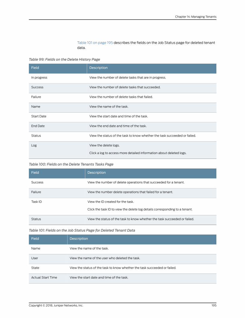
Table 101 on page 195 describes the fields on the Job Status page for deleted tenant
data.
Table 99: Fields on the Delete History Page
DescriptionField
View the number of delete tasks that are in progress.In progress
View the number of delete tasks that succeeded.Success
View the number of delete tasks that failed.Failure
View the name of the task.Name
View the start date and time of the task.Start Date
View the end date and time of the task.End Date
View the status of the task to knowwhether the task succeeded or failed.Status
View the delete logs.
Click a log to access more detailed information about deleted logs.
Log
Table 100: Fields on the Delete Tenants Tasks Page
DescriptionField
View the number of delete operations that succeeded for a tenant.Success
View the number delete operations that failed for a tenant.Failure
View the ID created for the task.
Click the task ID to view the delete log details corresponding to a tenant.
Task ID
View the status of the task to knowwhether the task succeeded or failed.Status
Table 101: Fields on the Job Status Page for Deleted Tenant Data
DescriptionField
View the name of the task.Name
View the name of the user who deleted the task.User
View the status of the task to knowwhether the task succeeded or failed.State
View the start date and time of the task.Actual Start Time
195Copyright © 2018, Juniper Networks, Inc.
Chapter 14: Managing Tenants
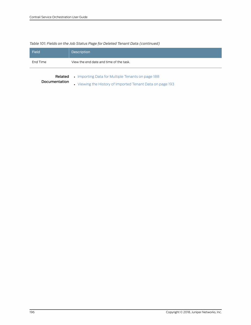
Table 101: Fields on the Job Status Page for Deleted Tenant Data (continued)
DescriptionField
View the end date and time of the task.End Time
RelatedDocumentation
• Importing Data for Multiple Tenants on page 188
• Viewing the History of Imported Tenant Data on page 193
Copyright © 2018, Juniper Networks, Inc.196
Contrail Service Orchestration User Guide
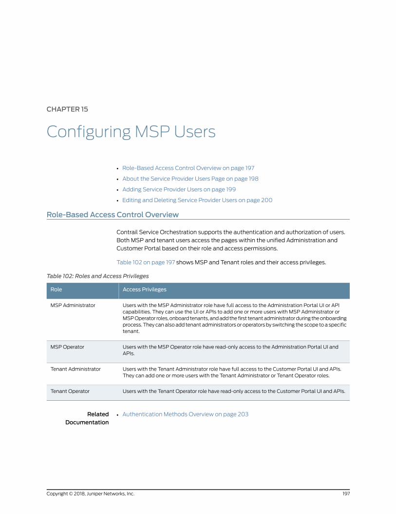
CHAPTER 15
Configuring MSP Users
• Role-Based Access Control Overview on page 197
• About the Service Provider Users Page on page 198
• Adding Service Provider Users on page 199
• Editing and Deleting Service Provider Users on page 200
Role-Based Access Control Overview
Contrail Service Orchestration supports the authentication and authorization of users.
Both MSP and tenant users access the pages within the unified Administration and
Customer Portal based on their role and access permissions.
Table 102 on page 197 shows MSP and Tenant roles and their access privileges.
Table 102: Roles and Access Privileges
Access PrivilegesRole
Users with the MSP Administrator role have full access to the Administration Portal UI or APIcapabilities. They can use the UI or APIs to add one or more users with MSP Administrator orMSPOperator roles, onboard tenants, andaddthe first tenantadministratorduring theonboardingprocess. Theycanalsoadd tenantadministratorsor operatorsby switching the scope toaspecifictenant.
MSP Administrator
Users with the MSP Operator role have read-only access to the Administration Portal UI andAPIs.
MSP Operator
Users with the Tenant Administrator role have full access to the Customer Portal UI and APIs.They can add one or more users with the Tenant Administrator or Tenant Operator roles.
Tenant Administrator
Users with the Tenant Operator role have read-only access to the Customer Portal UI and APIs.Tenant Operator
RelatedDocumentation
Authentication Methods Overview on page 203•
197Copyright © 2018, Juniper Networks, Inc.
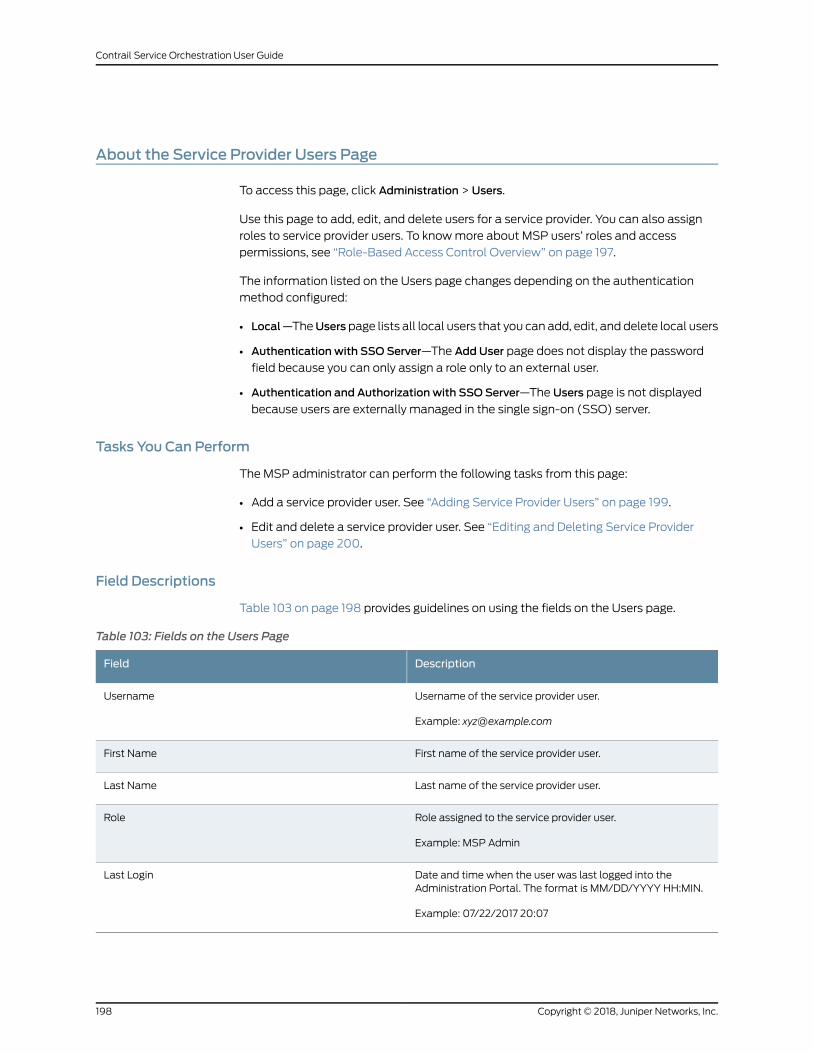
About the Service Provider Users Page
To access this page, click Administration > Users.
Use this page to add, edit, and delete users for a service provider. You can also assign
roles to service provider users. To knowmore about MSP users’ roles and access
permissions, see “Role-Based Access Control Overview” on page 197.
The information listed on the Users page changes depending on the authentication
method configured:
• Local—TheUserspage lists all local users that you can add, edit, and delete local users
• Authentication with SSO Server—The Add User page does not display the password
field because you can only assign a role only to an external user.
• Authentication and Authorization with SSO Server—The Users page is not displayed
because users are externally managed in the single sign-on (SSO) server.
Tasks You Can Perform
The MSP administrator can perform the following tasks from this page:
• Add a service provider user. See “Adding Service Provider Users” on page 199.
• Edit and delete a service provider user. See “Editing and Deleting Service Provider
Users” on page 200.
Field Descriptions
Table 103 on page 198 provides guidelines on using the fields on the Users page.
Table 103: Fields on the Users Page
DescriptionField
Username of the service provider user.
Example: [email protected]
Username
First name of the service provider user.First Name
Last name of the service provider user.Last Name
Role assigned to the service provider user.
Example: MSP Admin
Role
Date and time when the user was last logged into theAdministration Portal. The format is MM/DD/YYYY HH:MIN.
Example: 07/22/2017 20:07
Last Login
Copyright © 2018, Juniper Networks, Inc.198
Contrail Service Orchestration User Guide
RelatedDocumentation
Adding Service Provider Users on page 199•
• Editing and Deleting Service Provider Users on page 200
Adding Service Provider Users
Use this page to add service provider users and assign roles to service provider users.
After the service provider administrator adds the user, the user account is created in the
Contrail ServiceOrchestration (CSO) and the user receives an e-mailwith the initial login
credentials.
NOTE: Userswith theMSPOperator role have read-only access toCustomerPortal and APIs and they cannot add new users.
To add a service provider user:
1. Select Administration > Users.
The Users page appears.
2. Click the plus icon (+) or click Add User.
The Add User page appears.
3. Complete the configuration as described in Table 104 on page 199.
4. ClickOK to save the changes. If youwant to discard the changes, clickCancel instead.
The service provider user account is created in CSO.
To enhance the security related to your login credentials, an automatically generated
password is sent to the e-mail address that you have specified on the Add User page.
You are prompted to change the password after you login with the automatically
generated password. For more information about changing the password on first
login, see “Changing the Password on First Login” on page 7.
Table 104: Fields on the Add User Page
DescriptionField
Enter the first nameasa string of alphanumeric characters and the special characters space, underscore(_), and period (.). Themaximum length is 32 characters.
First Name
Enter the last nameas a string of alphanumeric characters and the special characters space, underscore(_), or period (.). Themaximum length is 32 characters.
Last Name
Enter a valid e-mail address in the user@domain format.Username (E-mail)
199Copyright © 2018, Juniper Networks, Inc.
Chapter 15: Configuring MSP Users
Table 104: Fields on the Add User Page (continued)
DescriptionField
Select the role—MSP Operator (default) or MSP Administrator—that you want to assign to the user.
• MSPAdministrator—Users with the MSP Administrator role have full access to the AdministrationPortal UI or API capabilities. They can use the UI or APIs to add one or more users with MSPAdministrator or MSP Operator roles, onboard tenants, and add the first tenant administrator duringthe onboarding process. They can also add tenant administrators or operators by switching the scopeto a specific tenant.
• MSPOperator—Users with theMSPOperator role have read-only access to Administration Portal andAPIs.
NOTE: Users with the MSP Operator role cannot add, edit, and delete users.
Role
RelatedDocumentation
About the Service Provider Users Page on page 198•
• Editing and Deleting Service Provider Users on page 200
Editing and Deleting Service Provider Users
You can edit the information of a service provider user, and delete one or more users.
NOTE: Users with the MSPOperator role have read-only access toAdministration Portal and APIs, and they cannot edit and delete users.
• Editing Service Provider Users on page 200
• Deleting Service Provider Users on page 201
Editing Service Provider Users
Tomodify a service provider user:
1. Select Administration > Users.
The Users page appears.
2. Select the user that you want to modify, and click the edit icon.
The Edit User page appears. The options available on the AddUser page are available
for editing.
NOTE: You cannot modify the Username (E-mail) field.
3. Update the fields as required.
4. ClickOK to save the changes. If youwant todiscard your changes, clickCancel instead.
Copyright © 2018, Juniper Networks, Inc.200
Contrail Service Orchestration User Guide
Themodified service provider user information is saved in CSO.
Deleting Service Provider Users
To delete service provide users:
1. Select Administration > Users.
The Users page appears.
2. Select the users that you want to delete and click the delete icon (X).
The Confirm Delete page appears.
3. Click Yes to delete the user or No to cancel the deletion.
If you click Yes, then the user is deleted and the user account is removed from the
CSO.
RelatedDocumentation
• About the Service Provider Users Page on page 198
• Adding Service Provider Users on page 199
201Copyright © 2018, Juniper Networks, Inc.
Chapter 15: Configuring MSP Users

Copyright © 2018, Juniper Networks, Inc.202
Contrail Service Orchestration User Guide
CHAPTER 16
Configuring Authentication
• Authentication Methods Overview on page 203
• About the Authentication Page on page 204
• Editing the Authentication Method on page 205
• Configuring a Single Sign-On Server on page 207
• Editing and Deleting SSO Servers on page 209
• Configuring SMTP Settings on page 210
AuthenticationMethods Overview
Contrail Service Orchestration supports single sign-on (SSO) authentication for the
unified portal. You can configure one SSO server for a service provider and another for
all its tenants.
You can authenticate and authorize users by using one of the following authentication
methods:
• Local—User accounts are maintained locally in CSO, and users are authenticated and
authorized by CSO.
• Authentication by using an SSO server—User accounts are maintained in the service
provider’s SSO server, but authorization information is stored in CSO. Users are
authenticated by using the credentials stored in the SSO server.
• Authentication and authorization by using anSSOserver—User accounts and user roles
are maintained in the service provider’s SSO server. Users are authenticated by the
SSO server and authorized by CSO by using Security Assertion Markup Language
(SAML) attributes.
When you log in to the unified Administration and Customer Portal, the login page is
displayed.To log in to theunifiedAdministrationandCustomerPortal, enter theusername
on the login page. If the usernamematches the username pattern configured for SSO,
then you are redirected to the SSO page. If the username does not match the username
pattern, youmust enter the password.
RelatedDocumentation
About the Authentication Page on page 204•
• Editing the Authentication Method on page 205
203Copyright © 2018, Juniper Networks, Inc.
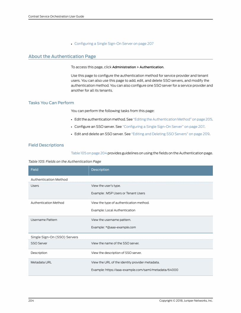
• Configuring a Single Sign-On Server on page 207
About the Authentication Page
To access this page, click Administration > Authentication.
Use this page to configure the authentication method for service provider and tenant
users. You can also use this page to add, edit, and delete SSO servers, andmodify the
authenticationmethod. You can also configure one SSO server for a service provider and
another for all its tenants.
Tasks You Can Perform
You can perform the following tasks from this page:
• Edit theauthenticationmethod.See “Editing theAuthenticationMethod”onpage205.
• Configure an SSO server. See “Configuring a Single Sign-On Server” on page 207.
• Edit and delete an SSO server. See “Editing and Deleting SSO Servers” on page 209.
Field Descriptions
Table 105onpage204providesguidelinesonusing the fieldson theAuthenticationpage.
Table 105: Fields on the Authentication Page
DescriptionField
AuthenticationMethod
View the user’s type.
Example : MSP Users or Tenant Users
Users
View the type of authentication method.
Example: Local Authentication
Authentication Method
View the username pattern.
Example: *@aaa-example.com
Username Pattern
Single Sign-On (SSO) Servers
View the name of the SSO server.SSO Server
View the description of SSO server.Description
View the URL of the identity provider metadata.
Example: https://aaa-example.com/saml/metadata/64000
Metadata URL
Copyright © 2018, Juniper Networks, Inc.204
Contrail Service Orchestration User Guide
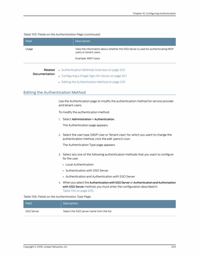
Table 105: Fields on the Authentication Page (continued)
DescriptionField
View the information about whether the SSO server is used for authenticating MSPusers or tenant users.
Example: MSP Users
Usage
RelatedDocumentation
Authentication Methods Overview on page 203•
• Configuring a Single Sign-On Server on page 207
• Editing the Authentication Method on page 205
Editing the AuthenticationMethod
Use the Authentication page to modify the authentication method for service provider
and tenant users.
Tomodify the authentication method:
1. Select Administration > Authentication.
The Authentication page appears.
2. Select the user type (MSP User or Tenant User) for which you want to change the
authentication method, click the edit (pencil) icon.
The Authentication Type page appears.
3. Select any one of the following authentication methods that you want to configure
for the user.
• Local Authentication
• Authentication with SSO Server
• Authentication and Authentication with SSO Server
4. Whenyouselect theAuthenticationwithSSOServerorAuthenticationandAuthorization
with SSO Servermethod, youmust enter the configuration described in
Table 106 on page 205.
Table 106: Fields on the Authentication Type Page
DescriptionField
Select the SSO server name from the list.SSO Server
205Copyright © 2018, Juniper Networks, Inc.
Chapter 16: Configuring Authentication
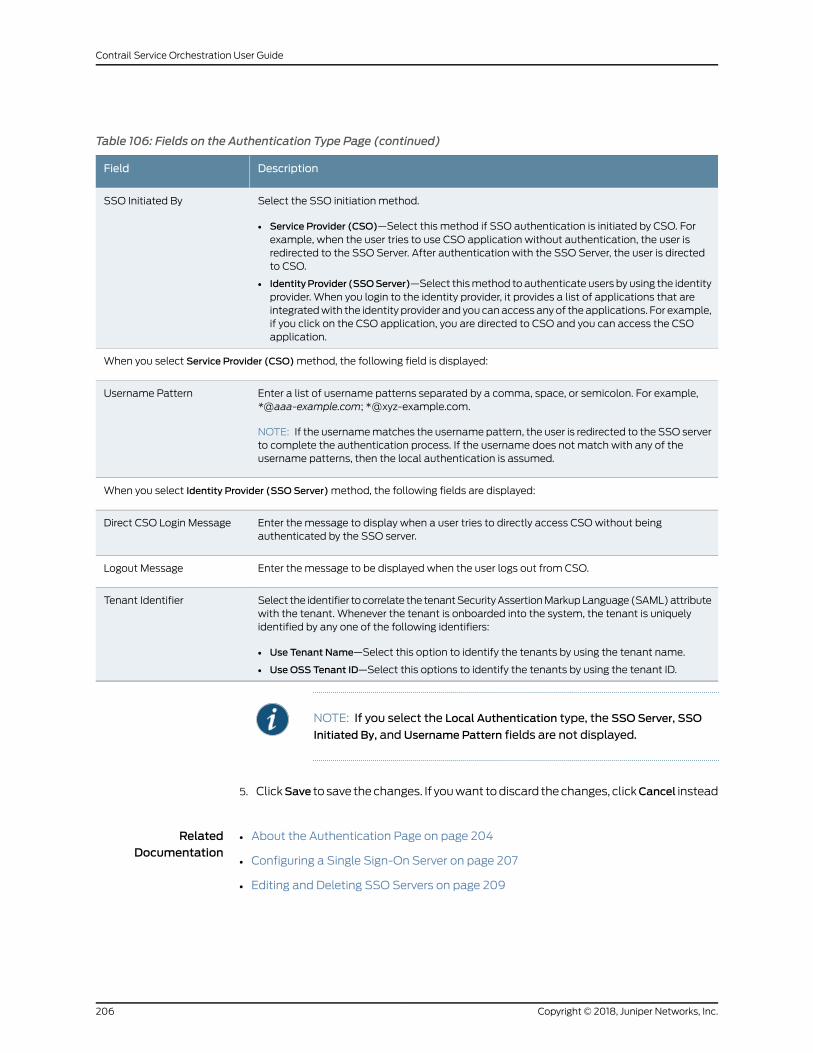
Table 106: Fields on the Authentication Type Page (continued)
DescriptionField
Select the SSO initiation method.
• Service Provider (CSO)—Select this method if SSO authentication is initiated by CSO. Forexample, when the user tries to use CSO application without authentication, the user isredirected to the SSO Server. After authentication with the SSO Server, the user is directedto CSO.
• IdentityProvider (SSOServer)—Select thismethod to authenticate users by using the identityprovider. When you login to the identity provider, it provides a list of applications that areintegratedwith the identity provider and you canaccess anyof theapplications. For example,if you click on the CSO application, you are directed to CSO and you can access the CSOapplication.
SSO Initiated By
When you select Service Provider (CSO)method, the following field is displayed:
Enter a list of username patterns separated by a comma, space, or semicolon. For example,*@aaa-example.com; *@xyz-example.com.
NOTE: If the usernamematches the username pattern, the user is redirected to the SSO serverto complete the authentication process. If the username does not match with any of theusername patterns, then the local authentication is assumed.
Username Pattern
When you select Identity Provider (SSO Server)method, the following fields are displayed:
Enter the message to display when a user tries to directly access CSOwithout beingauthenticated by the SSO server.
Direct CSO Login Message
Enter the message to be displayed when the user logs out from CSO.Logout Message
Select the identifier tocorrelate the tenantSecurityAssertionMarkupLanguage(SAML)attributewith the tenant. Whenever the tenant is onboarded into the system, the tenant is uniquelyidentified by any one of the following identifiers:
• Use Tenant Name—Select this option to identify the tenants by using the tenant name.
• Use OSS Tenant ID—Select this options to identify the tenants by using the tenant ID.
Tenant Identifier
NOTE: If you select the Local Authentication type, the SSOServer, SSO
Initiated By, and Username Pattern fields are not displayed.
5. ClickSave to save thechanges. If youwant todiscard thechanges, clickCancel instead
RelatedDocumentation
About the Authentication Page on page 204•
• Configuring a Single Sign-On Server on page 207
• Editing and Deleting SSO Servers on page 209
Copyright © 2018, Juniper Networks, Inc.206
Contrail Service Orchestration User Guide
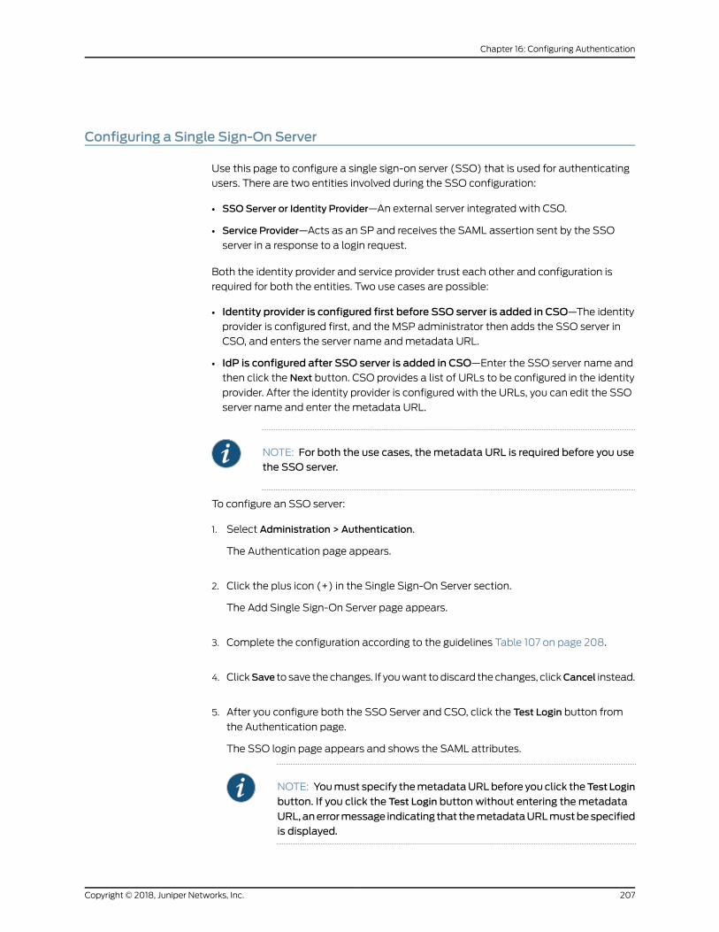
Configuring a Single Sign-On Server
Use this page to configure a single sign-on server (SSO) that is used for authenticating
users. There are two entities involved during the SSO configuration:
• SSOServer or Identity Provider—An external server integrated with CSO.
• Service Provider—Acts as an SP and receives the SAML assertion sent by the SSO
server in a response to a login request.
Both the identity provider and service provider trust each other and configuration is
required for both the entities. Two use cases are possible:
• Identity provider is configured first before SSO server is added in CSO—The identityprovider is configured first, and the MSP administrator then adds the SSO server in
CSO, and enters the server name andmetadata URL.
• IdP is configured after SSO server is added in CSO—Enter the SSO server name and
then click the Next button. CSO provides a list of URLs to be configured in the identity
provider. After the identity provider is configured with the URLs, you can edit the SSO
server name and enter the metadata URL.
NOTE: For both the use cases, themetadata URL is required before you usethe SSO server.
To configure an SSO server:
1. Select Administration > Authentication.
The Authentication page appears.
2. Click the plus icon (+) in the Single Sign-On Server section.
The Add Single Sign-On Server page appears.
3. Complete the configuration according to the guidelines Table 107 on page 208.
4. ClickSave to save thechanges. If youwant todiscard thechanges, clickCancel instead.
5. After you configure both the SSO Server and CSO, click the Test Login button from
the Authentication page.
The SSO login page appears and shows the SAML attributes.
NOTE: Youmust specify themetadataURLbefore you click theTest Login
button. If you click the Test Login button without entering themetadata
URL,anerrormessage indicating that themetadataURLmustbespecifiedis displayed.
207Copyright © 2018, Juniper Networks, Inc.
Chapter 16: Configuring Authentication
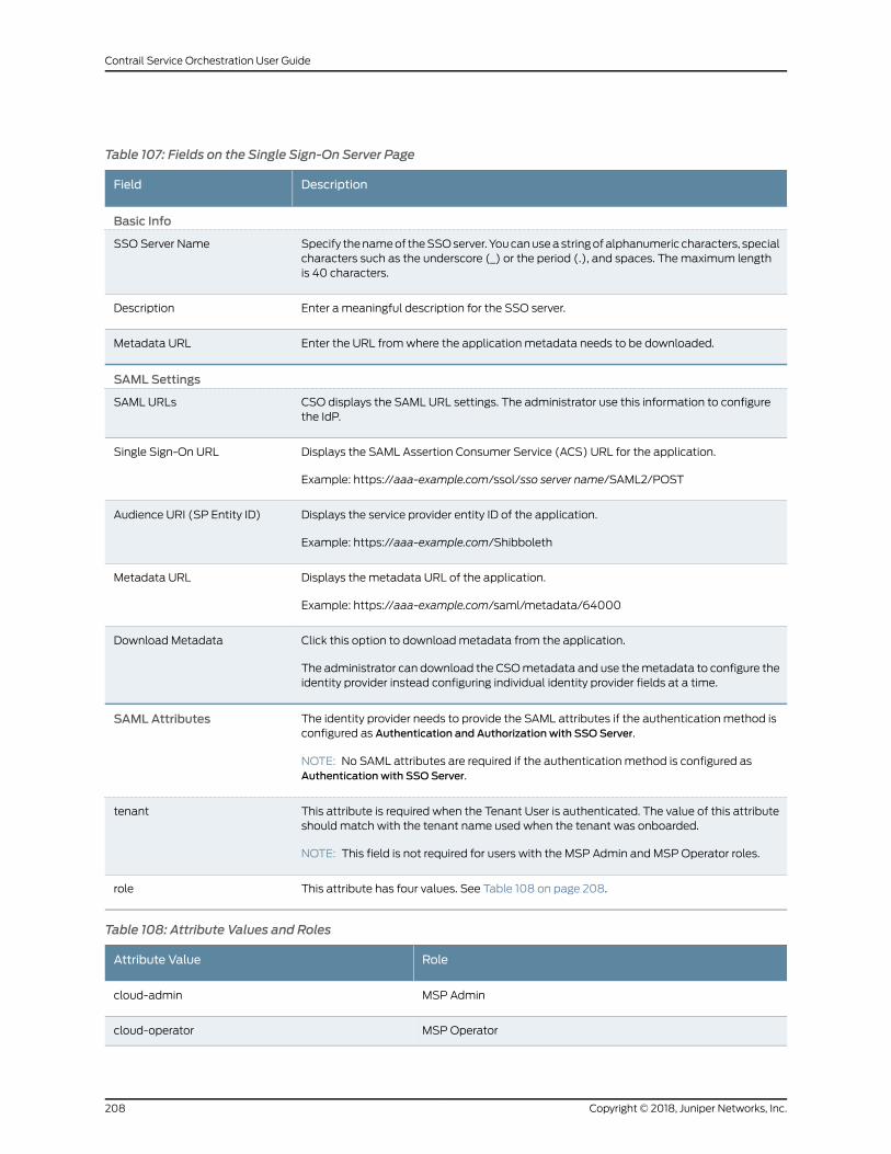
Table 107: Fields on the Single Sign-On Server Page
DescriptionField
Basic Info
Specify thenameof theSSOserver.Youcanuseastringofalphanumeric characters, specialcharacters such as the underscore (_) or the period (.), and spaces. Themaximum lengthis 40 characters.
SSO Server Name
Enter a meaningful description for the SSO server.Description
Enter the URL fromwhere the application metadata needs to be downloaded.Metadata URL
SAML Settings
CSO displays the SAML URL settings. The administrator use this information to configurethe IdP.
SAML URLs
Displays the SAML Assertion Consumer Service (ACS) URL for the application.
Example: https://aaa-example.com/ssol/sso server name/SAML2/POST
Single Sign-On URL
Displays the service provider entity ID of the application.
Example: https://aaa-example.com/Shibboleth
Audience URI (SP Entity ID)
Displays the metadata URL of the application.
Example: https://aaa-example.com/saml/metadata/64000
Metadata URL
Click this option to downloadmetadata from the application.
The administrator can download the CSOmetadata and use themetadata to configure theidentity provider instead configuring individual identity provider fields at a time.
Download Metadata
The identity provider needs to provide the SAML attributes if the authentication method isconfigured as Authentication and Authorization with SSO Server.
NOTE: No SAML attributes are required if the authentication method is configured asAuthentication with SSO Server.
SAML Attributes
This attribute is required when the Tenant User is authenticated. The value of this attributeshould match with the tenant name used when the tenant was onboarded.
NOTE: This field is not required for users with the MSP Admin and MSP Operator roles.
tenant
This attribute has four values. See Table 108 on page 208.role
Table 108: Attribute Values and Roles
RoleAttribute Value
MSP Admincloud-admin
MSP Operatorcloud-operator
Copyright © 2018, Juniper Networks, Inc.208
Contrail Service Orchestration User Guide
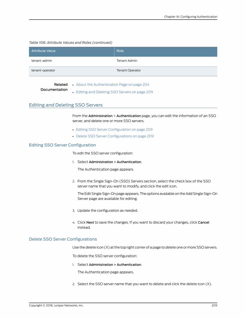
Table 108: Attribute Values and Roles (continued)
RoleAttribute Value
Tenant Admintenant-admin
Tenant Operatortenant-operator
RelatedDocumentation
About the Authentication Page on page 204•
• Editing and Deleting SSO Servers on page 209
Editing and Deleting SSO Servers
From the Administration > Authentication page, you can edit the information of an SSO
server, and delete one or more SSO servers.
• Editing SSO Server Configuration on page 209
• Delete SSO Server Configurations on page 209
Editing SSO Server Configuration
To edit the SSO server configuration:
1. Select Administration > Authentication.
The Authentication page appears.
2. From the Single Sign-On (SSO) Servers section, select the check box of the SSO
server name that you want to modify, and click the edit icon.
TheEditSingleSign-Onpageappears.Theoptionsavailableon theAddSingleSign-On
Server page are available for editing.
3. Update the configuration as needed.
4. Click Next to save the changes. If you want to discard your changes, click Cancel
instead.
Delete SSO Server Configurations
Use thedelete icon (X)at the top right cornerofapage todeleteoneormoreSSOservers.
To delete the SSO server configuration:
1. Select Administration > Authentication.
The Authentication page appears.
2. Select the SSO server name that you want to delete and click the delete icon (X).
209Copyright © 2018, Juniper Networks, Inc.
Chapter 16: Configuring Authentication
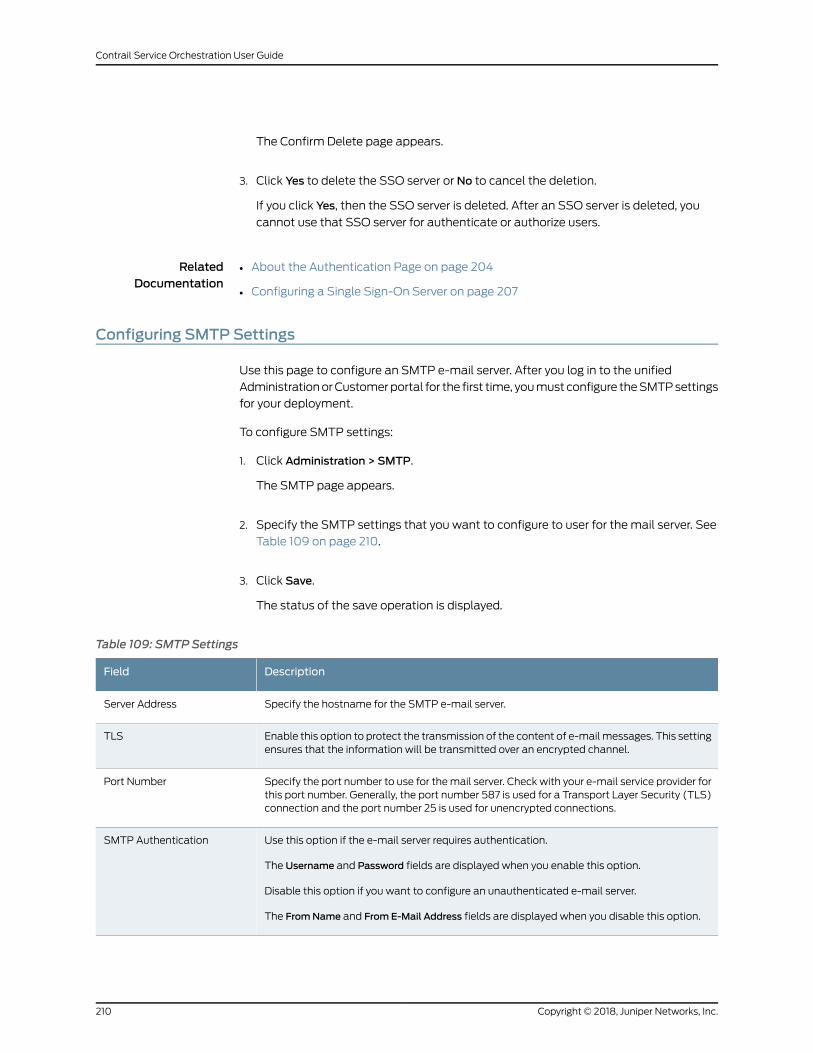
The Confirm Delete page appears.
3. Click Yes to delete the SSO server or No to cancel the deletion.
If you click Yes, then the SSO server is deleted. After an SSO server is deleted, you
cannot use that SSO server for authenticate or authorize users.
RelatedDocumentation
About the Authentication Page on page 204•
• Configuring a Single Sign-On Server on page 207
Configuring SMTP Settings
Use this page to configure an SMTP e-mail server. After you log in to the unified
AdministrationorCustomerportal for the first time, youmust configure theSMTPsettings
for your deployment.
To configure SMTP settings:
1. Click Administration > SMTP.
The SMTP page appears.
2. Specify the SMTP settings that you want to configure to user for the mail server. See
Table 109 on page 210.
3. Click Save.
The status of the save operation is displayed.
Table 109: SMTP Settings
DescriptionField
Specify the hostname for the SMTP e-mail server.Server Address
Enable this option to protect the transmission of the content of e-mailmessages. This settingensures that the information will be transmitted over an encrypted channel.
TLS
Specify the port number to use for themail server. Check with your e-mail service provider forthis port number. Generally, the port number 587 is used for a Transport Layer Security (TLS)connection and the port number 25 is used for unencrypted connections.
Port Number
Use this option if the e-mail server requires authentication.
The Username and Password fields are displayed when you enable this option.
Disable this option if you want to configure an unauthenticated e-mail server.
The FromName and From E-Mail Address fields are displayed when you disable this option.
SMTP Authentication
Copyright © 2018, Juniper Networks, Inc.210
Contrail Service Orchestration User Guide
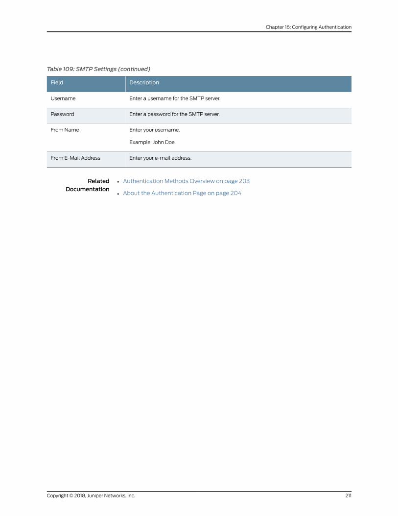
Table 109: SMTP Settings (continued)
DescriptionField
Enter a username for the SMTP server.Username
Enter a password for the SMTP server.Password
Enter your username.
Example: John Doe
From Name
Enter your e-mail address.From E-Mail Address
RelatedDocumentation
• Authentication Methods Overview on page 203
• About the Authentication Page on page 204
211Copyright © 2018, Juniper Networks, Inc.
Chapter 16: Configuring Authentication

Copyright © 2018, Juniper Networks, Inc.212
Contrail Service Orchestration User Guide
CHAPTER 17
Configuring Licenses
• About the License Files Page on page 213
• Uploading a License File on page 214
• Editing and Deleting Licenses on page 215
• Pushing a License to Devices on page 216
About the License Files Page
To access this page, click Administration > Licenses.
You can use the License Files page to upload licenses for devices and virtual network
services from your local file system. Each license file should contain only one license key.
A license key is required to enable various features including virtual network services such
as application-based routing, application monitoring, and vSRX security features.
Tasks You Can Perform
You can perform the following tasks from this page:
• Add License Files. See “Uploading a License File” on page 214.
• Edit and delete license entries. See “Editing and Deleting Licenses” on page 215.
• Push Licenses to devices. See “Pushing a License to Devices” on page 216
• View details of a license. Click the details icon that appears when you hover over the
name of an image or clickMore > Details. See “Viewing Object Details” on page 14.
Field Descriptions
Table 110 on page 213 describes the fields on the License Files page.
Table 110: Fields on the License Files Page
DescriptionField
Displays the filename of the license.
Example: license_Image_v1
File Name
213Copyright © 2018, Juniper Networks, Inc.
Table 110: Fields on the License Files Page (continued)
DescriptionField
Displays the description of the license.
Example: License file for application routing.
Description
Displays the name of the tenant if the license is associated with a tenant.
Example: Tenant 1
Tenant
Displays the administrator who uploaded the license.
Example: test_admin
Uploaded By
Displays the date and time when the license was uploaded.
Example: May 2, 2018, 1:34:37 PM
Uploaded
RelatedDocumentation
Uploading a License File on page 214•
Uploading a License File
To upload a license file:
1. Click Administration > Licenses.
The License Files page appears.
2. Click the plus icon (+).
The Add Licenses page appears.
3. In the License File field, specify the location of the license file that youwant to upload.
Alternatively, you can click Browse to navigate to the file location and select the file.
NOTE: Each license file should contain only one license key.
4. (Optional) From the Tenants list, select the tenant to which you want to associate
the license file.
If you associate a licensewith a tenant, you can apply that license only to devices that
belong to that tenant. If a tenant has licenses associated with the tenant, when a
device is activated during ZTP, a matching license from the licenses associated with
the tenant is downloaded to the device.
You can apply a license that is not associated with a tenant to any device of any of
the tenants. During ZTP, when a device is activated for a tenant that does not have
Copyright © 2018, Juniper Networks, Inc.214
Contrail Service Orchestration User Guide
any license associated with it, a matching license from the licenses that are not
associated with any tenant is downloaded to the device.
5. In the Description field, enter a description for the license that you want to upload.
6. ClickOK to upload the license.
You are returned to the License Files page.
RelatedDocumentation
About the License Files Page on page 213•
• Device Images Overview on page 125
Editing and Deleting Licenses
The following sectionsdescribe theprocedure for editinganddeletinguploaded licenses:
• Editing a License Entry on page 215
• Deleting a License on page 215
Editing a License Entry
You can edit a license entry to modify the description for the license file.
1. Click Administration > Licenses.
The License Files page appears.
2. Select the license forwhich youwant tomodify the description and click the Edit icon.
The Update License page appears.
3. Update the description.
4. ClickOK to save the changes. To discard the changes, click Cancel.
If you click Cancel, a confirmation message appears. Click Yes to confirm that you
want to cancel the update.
Deleting a License
To delete a license:
1. Click Administration > Licenses.
The License Files page appears.
2. Select the license that you want to delete and click the delete icon.
215Copyright © 2018, Juniper Networks, Inc.
Chapter 17: Configuring Licenses
3. In the confirmation message, click Yes to delete the license.
To cancel the delete operation, click No.
Pushing a License to Devices
You can push licenses on to devices from the Licenses page of the Administration portal.
If a license isassociatedwitha tenant, youcanpush that licenseonly todevicesassociated
with that tenant. However, if no tenant is associated with a license, you can apply the
license to any device that belongs to any tenant.
When a license is applied to a device, the license information is added to the device
object. When the same license is pushed to the device again, the a device-level error
message is created. Similarly, if a pushed license does not match a device, the device
generates an error message.
To push a license to a device:
1. Click Administration > Licenses.
The License Files page appears.
2. Select the license that you want to push to a device.
The Push License button is enabled.
3. Click the Push License button.
The Push License page appears.
4. From the Tenants list, select the tenant associatedwith the site and devices to which
you want to apply the license.
NOTE: If the licensehasalreadybeenassociatedwitha tenant, youcannotselect a different tenant. You can apply the license only to the sites anddevices associated with the tenant.
Sites and devices associated with the selected tenant appear.
5. Select the sites and devices to which you want to apply the license and click Push
Licenses.
CSO applies the license to the selected devices.
RelatedDocumentation
• About the License Files Page on page 213
• Editing and Deleting Licenses on page 215
Copyright © 2018, Juniper Networks, Inc.216
Contrail Service Orchestration User Guide
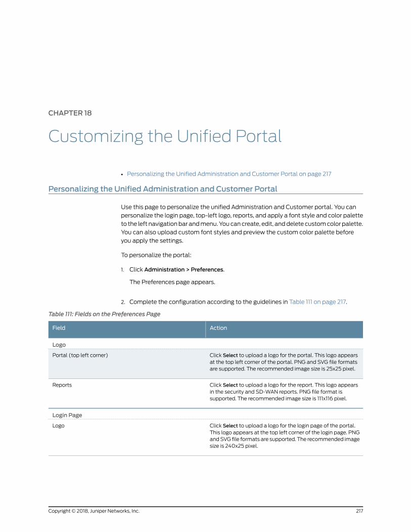
CHAPTER 18
Customizing the Unified Portal
• Personalizing the Unified Administration and Customer Portal on page 217
Personalizing the Unified Administration and Customer Portal
Use this page to personalize the unified Administration and Customer portal. You can
personalize the login page, top-left logo, reports, and apply a font style and color palette
to the left navigationbar andmenu. Youcancreate, edit, anddelete customcolor palette.
You can also upload custom font styles and preview the custom color palette before
you apply the settings.
To personalize the portal:
1. Click Administration > Preferences.
The Preferences page appears.
2. Complete the configuration according to the guidelines in Table 111 on page 217.
Table 111: Fields on the Preferences Page
ActionField
Logo
Click Select to upload a logo for the portal. This logo appearsat the top left corner of the portal. PNG and SVG file formatsare supported. The recommended image size is 25x25 pixel.
Portal (top left corner)
Click Select to upload a logo for the report. This logo appearsin the security and SD-WAN reports. PNG file format issupported. The recommended image size is 111x116 pixel.
Reports
Login Page
Click Select to upload a logo for the login page of the portal.This logo appears at the top left corner of the login page. PNGandSVG file formats are supported. The recommended imagesize is 240x25 pixel.
Logo
217Copyright © 2018, Juniper Networks, Inc.
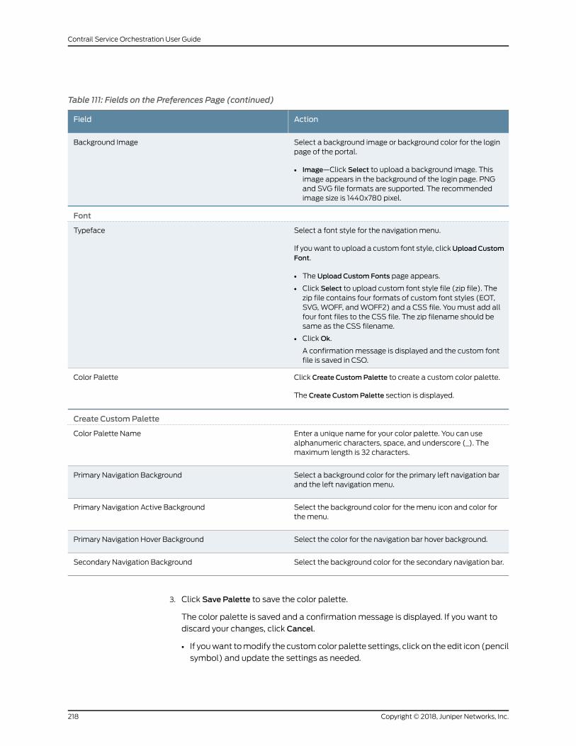
Table 111: Fields on the Preferences Page (continued)
ActionField
Select a background image or background color for the loginpage of the portal.
• Image—Click Select to upload a background image. Thisimage appears in the background of the login page. PNGand SVG file formats are supported. The recommendedimage size is 1440x780 pixel.
Background Image
Font
Select a font style for the navigation menu.
If youwant to upload a custom font style, clickUploadCustomFont.
• The Upload Custom Fonts page appears.
• Click Select to upload custom font style file (zip file). Thezip file contains four formats of custom font styles (EOT,SVG, WOFF, andWOFF2) and a CSS file. Youmust add allfour font files to the CSS file. The zip filename should besame as the CSS filename.
• ClickOk.
A confirmation message is displayed and the custom fontfile is saved in CSO.
Typeface
Click Create CustomPalette to create a custom color palette.
The Create CustomPalette section is displayed.
Color Palette
Create CustomPalette
Enter a unique name for your color palette. You can usealphanumeric characters, space, and underscore (_). Themaximum length is 32 characters.
Color Palette Name
Select a background color for the primary left navigation barand the left navigation menu.
Primary Navigation Background
Select the background color for the menu icon and color forthe menu.
Primary Navigation Active Background
Select the color for the navigation bar hover background.Primary Navigation Hover Background
Select the background color for the secondary navigation bar.Secondary Navigation Background
3. Click Save Palette to save the color palette.
The color palette is saved and a confirmation message is displayed. If you want to
discard your changes, click Cancel.
• If youwant tomodify the customcolor palette settings, click on the edit icon (pencil
symbol) and update the settings as needed.
Copyright © 2018, Juniper Networks, Inc.218
Contrail Service Orchestration User Guide
• If you want to delete the custom color palette, click the delete icon (X) next to the
color palette.
• The Confirm Color Palette Delete page appears.
• Click Yes to confirm the deletion. The custom color palette is deleted.
4. Click Preview to preview the color palette before you apply the settings.
A confirmation message is displayed and you can preview the theme applied to the
portal.
5. Click Apply to apply the settings.
The settings are applied to the portal.
If you want to discard your changes, click Cancel.
RelatedDocumentation
• Logging in to Administration Portal on page 5
219Copyright © 2018, Juniper Networks, Inc.
Chapter 18: Customizing the Unified Portal

Copyright © 2018, Juniper Networks, Inc.220
Contrail Service Orchestration User Guide
CHAPTER 19
Managing Signature Database
• Signature Database Overview on page 221
• About the Active Database Page on page 222
• Downloading a Signature Database on page 223
• Download Locations for Signature Database on page 224
• Installing Signatures on page 225
Signature Database Overview
The Application Firewall signature database includes signature definitions of attacks
and applications that can be used to identify applications for tracking firewall policies
and quality-of-service (QoS) prioritization.
Contrail Service Orchestration (CSO) enables you to download the signature database.
During a download, the complete signature database is downloaded, and the download
might take some time to complete. You can track the progress of the download by using
job details.
All of the downloaded signatures are created as a default project in read-onlymode. The
configurations that are downloaded are also saved as a default project.
RelatedDocumentation
About the Active Database Page on page 222•
• Downloading a Signature Database on page 223
• Installing Signatures on page 225
221Copyright © 2018, Juniper Networks, Inc.
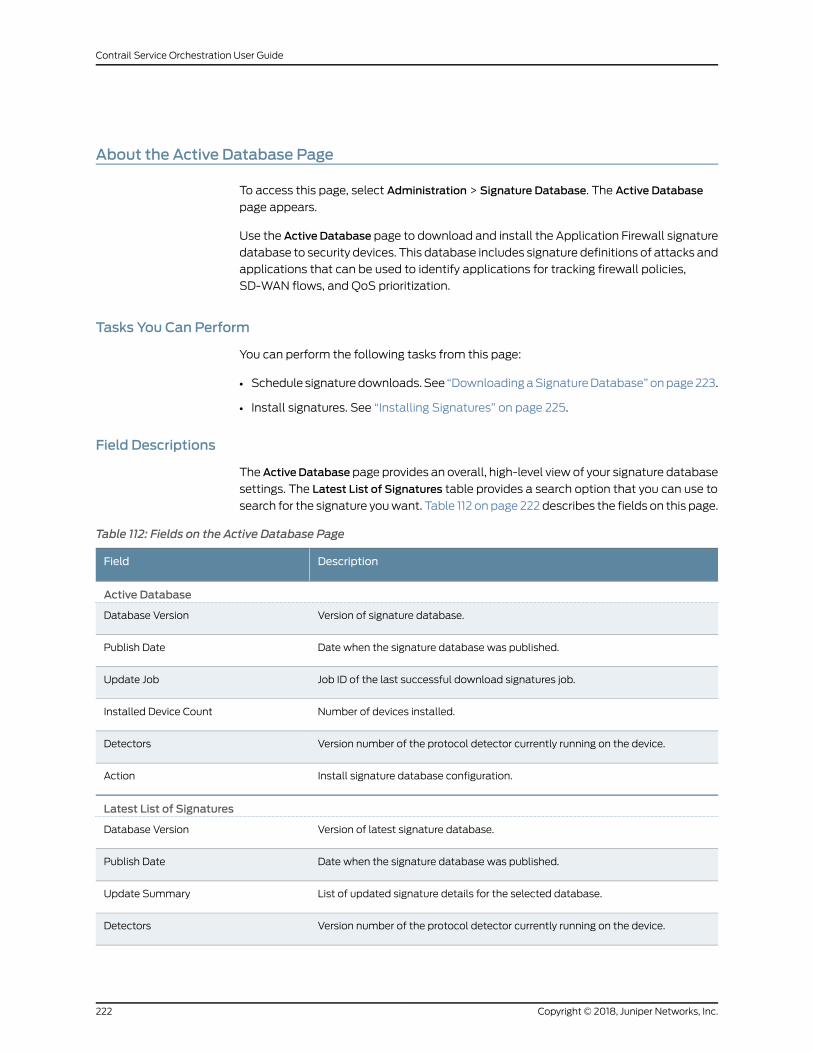
About the Active Database Page
To access this page, select Administration > Signature Database. The Active Database
page appears.
Use the Active Database page to download and install the Application Firewall signature
database to security devices. This database includes signature definitions of attacks and
applications that can be used to identify applications for tracking firewall policies,
SD-WAN flows, and QoS prioritization.
Tasks You Can Perform
You can perform the following tasks from this page:
• Schedule signaturedownloads.See “DownloadingaSignatureDatabase”onpage223.
• Install signatures. See “Installing Signatures” on page 225.
Field Descriptions
TheActiveDatabase page provides an overall, high-level view of your signature database
settings. The Latest List of Signatures table provides a search option that you can use to
search for the signature youwant. Table 112 on page 222 describes the fields on this page.
Table 112: Fields on the Active Database Page
DescriptionField
Active Database
Version of signature database.Database Version
Date when the signature database was published.Publish Date
Job ID of the last successful download signatures job.Update Job
Number of devices installed.Installed Device Count
Version number of the protocol detector currently running on the device.Detectors
Install signature database configuration.Action
Latest List of Signatures
Version of latest signature database.Database Version
Date when the signature database was published.Publish Date
List of updated signature details for the selected database.Update Summary
Version number of the protocol detector currently running on the device.Detectors
Copyright © 2018, Juniper Networks, Inc.222
Contrail Service Orchestration User Guide
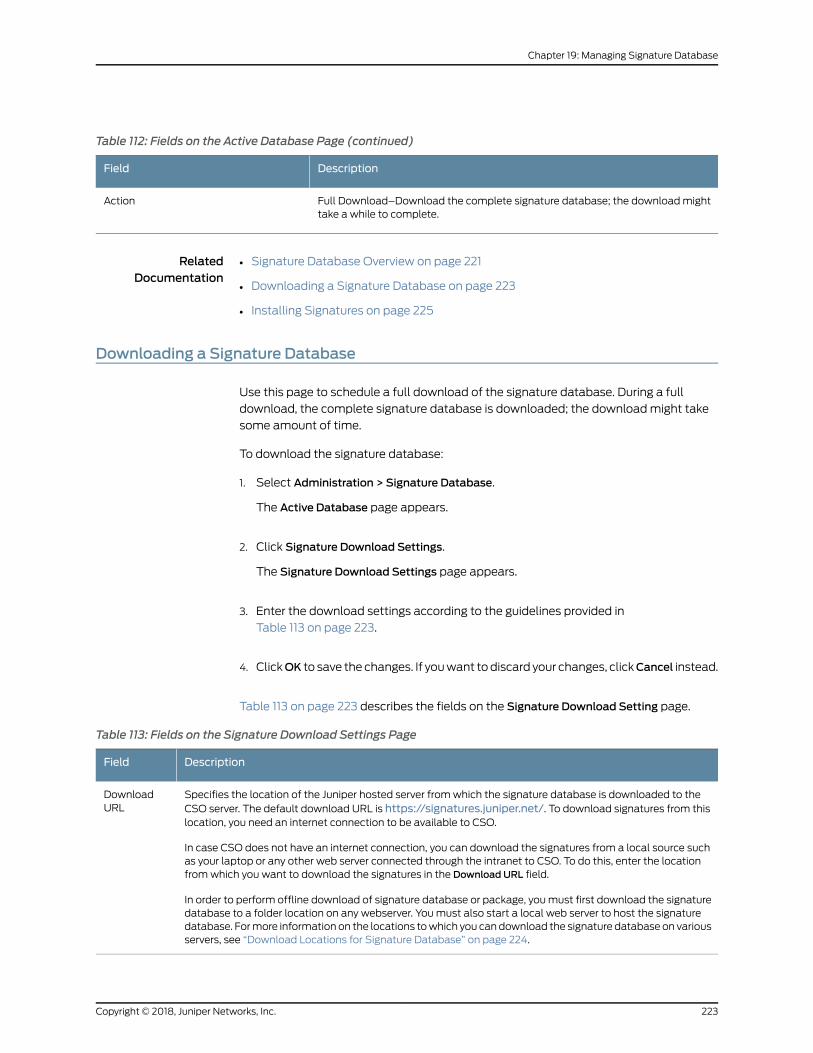
Table 112: Fields on the Active Database Page (continued)
DescriptionField
Full Download–Download the complete signature database; the downloadmighttake a while to complete.
Action
RelatedDocumentation
Signature Database Overview on page 221•
• Downloading a Signature Database on page 223
• Installing Signatures on page 225
Downloading a Signature Database
Use this page to schedule a full download of the signature database. During a full
download, the complete signature database is downloaded; the downloadmight take
some amount of time.
To download the signature database:
1. Select Administration > Signature Database.
The Active Database page appears.
2. Click Signature Download Settings.
The Signature Download Settings page appears.
3. Enter the download settings according to the guidelines provided in
Table 113 on page 223.
4. ClickOK to save the changes. If youwant todiscard your changes, clickCancel instead.
Table 113 on page 223 describes the fields on the Signature Download Setting page.
Table 113: Fields on the Signature Download Settings Page
DescriptionField
Specifies the location of the Juniper hosted server fromwhich the signature database is downloaded to theCSO server. The default download URL is https://signatures.juniper.net/. To download signatures from thislocation, you need an internet connection to be available to CSO.
In case CSO does not have an internet connection, you can download the signatures from a local source suchas your laptop or any other web server connected through the intranet to CSO. To do this, enter the locationfromwhich you want to download the signatures in the Download URL field.
In order to perform offline download of signature database or package, youmust first download the signaturedatabase to a folder location on any webserver. Youmust also start a local web server to host the signaturedatabase. Formore information on the locations towhich you candownload the signature database on variousservers, see “Download Locations for Signature Database” on page 224.
DownloadURL
223Copyright © 2018, Juniper Networks, Inc.
Chapter 19: Managing Signature Database
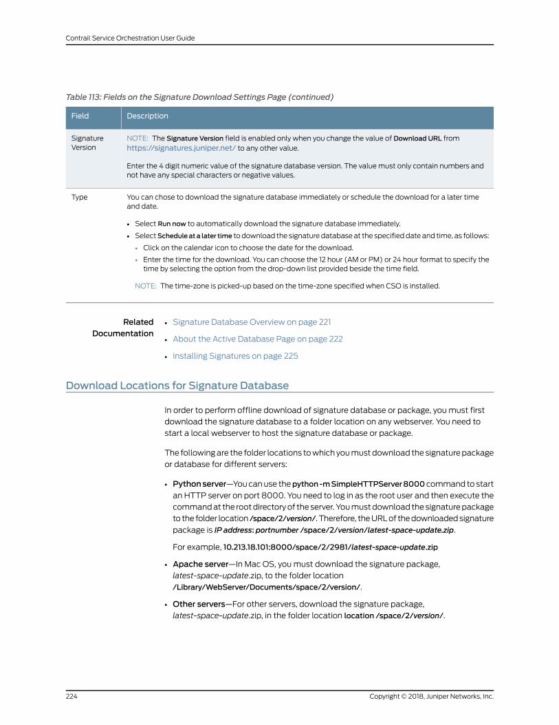
Table 113: Fields on the Signature Download Settings Page (continued)
DescriptionField
NOTE: The Signature Version field is enabled only when you change the value of Download URL fromhttps://signatures.juniper.net/ to any other value.
Enter the 4 digit numeric value of the signature database version. The value must only contain numbers andnot have any special characters or negative values.
SignatureVersion
You can chose to download the signature database immediately or schedule the download for a later timeand date.
• Select Run now to automatically download the signature database immediately.
• SelectScheduleata later time to download the signature databaseat the specifieddate and time, as follows:
• Click on the calendar icon to choose the date for the download.
• Enter the time for the download. You can choose the 12 hour (AM or PM) or 24 hour format to specify thetime by selecting the option from the drop-down list provided beside the time field.
NOTE: The time-zone is picked-up based on the time-zone specified when CSO is installed.
Type
RelatedDocumentation
Signature Database Overview on page 221•
• About the Active Database Page on page 222
• Installing Signatures on page 225
Download Locations for Signature Database
In order to perform offline download of signature database or package, youmust first
download the signature database to a folder location on any webserver. You need to
start a local webserver to host the signature database or package.
The followingare the folder locations towhichyoumustdownload thesignaturepackage
or database for different servers:
• Pythonserver—Youcanuse thepython-mSimpleHTTPServer8000command to start
an HTTP server on port 8000. You need to log in as the root user and then execute the
commandat the rootdirectoryof theserver.Youmustdownload thesignaturepackage
to the folder location /space/2/version/. Therefore, theURLof thedownloadedsignature
package is IP address: portnumber /space/2/version/latest-space-update.zip.
For example, 10.213.18.101:8000/space/2/2981/latest-space-update.zip
• Apache server—In Mac OS, youmust download the signature package,latest-space-update.zip, to the folder location
/Library/WebServer/Documents/space/2/version/.
• Other servers—For other servers, download the signature package,latest-space-update.zip, in the folder location location /space/2/version/.
Copyright © 2018, Juniper Networks, Inc.224
Contrail Service Orchestration User Guide
RelatedDocumentation
Application Signatures Overview on page 173•
• Signature Database Overview on page 613
Installing Signatures
After the signature database is downloaded, you can install the active database.
NOTE: Youmust install theapplication identification licensebefore installingthe signature database. For the installation procedure, refer to the KnownBehavior section of the Cloud CPE Solution Release Notes (available athttps://www.juniper.net/documentation/en_US/release-independent/nfv/
information-products/pathway-pages/index.html).
To install the signature database:
1. Select Administration > Signature Database.
2. Click Install Signatures.
The Install Signatures page appears.
3. Youcanview the summaryof active signaturedatabaseversion,whichwill be installed
on your device.
4. Click the check box next to the devices on which you want to install the signature
database.
You can also search, sort, or filter this information.
5. Select Run now to set the signature database to automatically install immediately.
6. SelectScheduleata later time to set thesignaturedatabase toautomaticallydownload
at the specified time and to take the following actions:
a. Choose a date by clicking the date picker icon.
b. Enter the time.
c. Select the time format from the drop-down list.
7. ClickOK.
The signature database installation is complete.
225Copyright © 2018, Juniper Networks, Inc.
Chapter 19: Managing Signature Database
RelatedDocumentation
• Signature Database Overview on page 221
• About the Active Database Page on page 222
• Downloading a Signature Database on page 223
Copyright © 2018, Juniper Networks, Inc.226
Contrail Service Orchestration User Guide
PART 2
Customer Portal
• Introduction on page 229
• Using the Dashboard on page 237
• Managing Objects on page 241
• Monitoring Security Alerts and Alarms on page 243
• Monitoring Security and Device Events on page 251
• Monitoring SD-WAN Events on page 279
• Monitoring Applications on page 283
• Monitoring Threats on page 297
• Monitoring Jobs on page 303
• Managing Devices on page 307
• Managing Device Images on page 323
• Managing Network Services on page 327
• Managing Firewall Policies on page 343
• Unified Threat Management on page 395
• Managing SD-WAN on page 437
• Managing NAT Policies on page 451
• Managing SSL Proxies on page 481
• Managing Shared Objects on page 505
• Managing Deployments on page 529
• Managing Sites on page 535
• Managing Site Groups on page 583
• Security Reports on page 585
• SD-WAN Reports on page 595
• Managing Tenant Users on page 605
• Licenses on page 611
• Signature Database on page 613
• Managing Certificates on page 617
• Managing Juniper Identity Management Service on page 623
227Copyright © 2018, Juniper Networks, Inc.

Copyright © 2018, Juniper Networks, Inc.228
Contrail Service Orchestration User Guide
CHAPTER 20
Introduction
• Unified Administration and Customer Portal Overview on page 229
• Customer Portal Overview on page 230
• Switching the Tenant Scope on page 231
• Accessing Customer Portal on page 231
• Setting Up Your Network with Customer Portal on page 232
• Changing the Password on First Login on page 233
• Changing the Customer Portal Password on page 234
• Resetting the Password on page 234
• Extending the User Login Session on page 236
Unified Administration and Customer Portal Overview
Contrail Service Orchestration supports a unified portal for both service provider users
and tenant users and for the servicesmanagedand consumedby the administrators and
tenants.
The unified portal contains the features of vCPE, uCPE, and SD-WAN for both
AdministrationandCustomerportals; enforces role-basedaccess control (RBAC),which
prevents tenants from accessing administrator data; and supports different backend
authentication methods for service provider users and tenant users.
The unified portal enable service providers to deploy Juniper Networks security features
as a virtualized network function (VNF) function either in distributed or centralizedmode
or in the branch SRX Series device. This VNF provides advanced firewall and Network
Address Translation (NAT)management capabilities to end users from a single pane of
glass (SPOG)user interface, inamultitenantenvironment.Serviceprovideradministrators
are able tomanage all phases of the security policy life cyclemore quickly and intuitively,
from policy creation through deployment.
Firewall and NATmanagement features include policy configuration such as rule
reordering, event viewer for firewall andNATevents, alertsandalarms, logsanddashboard
widgets. All features have RBAC enforced, which enables either the MSP administrator
or the tenant administrator to configure policies for the tenant.
229Copyright © 2018, Juniper Networks, Inc.
The unified portal also provides SD-WAN capabilities with integrated firewall, NAT
management, and device management.
RelatedDocumentation
Customer Portal Overview on page 230•
• Switching the Tenant Scope on page 231
• Firewall Policy Overview on page 343
• SLA Profiles and SD-WAN Policies Overview on page 437
• NAT Policies Overview on page 452
Customer Portal Overview
You use Customer Portal to activate andmanage sites, customer premises equipment
(CPE) devices, and network services in your network. Your service provider sets up the
network topology, assigns network services to you, and provides initial login credentials
for Customer Portal. You can change your password through Customer Portal after you
log in for the first time.
Your network uses one of the following deployment topologies:
• A centralized deployment
In a centralized deployment, virtualized network functions (VNFs) reside in a service
provider’s cloud in a network point of presence (POP). Sites that access network
services in this way are called cloud sites in this documentation.
• A distributed deployment
In the distributed deployment, VNFs reside on a CPE device located at a customer’s
site. These sites are called on-premise sites in this documentation.
• A combined centralized and distributed deployment
In this deployment, your network contains both cloud sites and on-premise sites. VNFs
for a cloud site reside in the service provider’s cloud and VNFs for an on-premise sites
reside on the CPE device.
Each connection for a cloud site and each on-premise site can support one network
service, although use of a network service on any connection or device is optional.
NOTE: NFX250 devices activate automatically when you power them upand configure basic connectivity settings, and you do not need to activatethese devices through Customer Portal. See the NFX250 documentation at:https://www.juniper.net/documentation/en_US/release-independent/junos/
information-products/pathway-pages/nfx-series/product/
RelatedDocumentation
Accessing Customer Portal on page 231•
• Changing the Customer Portal Password on page 234
Copyright © 2018, Juniper Networks, Inc.230
Contrail Service Orchestration User Guide
Switching the Tenant Scope
Administration Portal users can change the tenant scope from all tenants to a specific
tenant by using the tenant switcher displayed on the banner.
When you switch scope from all tenants to a specific tenant, the menu and pages
displayed are almost the same as those displayed for Customer Portal users, with some
additional actions visible to the Administration Portal users. When you switch back to
the All Tenants scope, the menu and pages for the Administration Portal are displayed.
To switch from one scope to another:
• From the top right corner of the page, select the All Tenants scope to access
AdministrationPortal or selecta specific tenant (for example, aaa) toaccessCustomer
Portal. Themenuandpages forAdministrationPortal orCustomerPortal aredisplayed
based on the scope selected from the drop-down list.
RelatedDocumentation
Unified Administration and Customer Portal Overview on page 229•
• Role-Based Access Control Overview on page 605
Accessing Customer Portal
To start Customer Portal:
1. Obtain the following information from your service provider:
• IP address for the Customer Portal host.
• Login credentials:
• Username
• Password
2. Using aWeb browser, access the URL for Customer Portal.
For example, if the IPaddressof thehost onwhichCustomerPortal resides is 192.0.2.1,
the URL is https://192.0.2.1.
NOTE: We recommend that you use Google Chrome Version 60 or laterto access the Contrail Service Orchestration (CSO) GUIs.
3. Log in with the credentials provided.
The Customer Portal Dashboard page appears and you can now start to activate
sites.
From CSO Release 3.1 onward, the customer portal functionality has been enhanced
to provide a richer user experience. Themenu bar on the left-hand side of the every
231Copyright © 2018, Juniper Networks, Inc.
Chapter 20: Introduction
page allows you to access the different tasks easily. The top-level menu items are
listed in Table 114 on page 232.
Table 114: Customer Portal Menu
DescriptionMenu Name
Configurable dashboard that offers you a customized view of network services through itswidgets
Dashboard
Monitor alerts and alarms, security, device, and software-definedWAN (SD-WAN) events;applications and jobs
Monitor
Device and software imagemanagementResources
Configure network services, shared objects, and policies (firewall, NAT, SD-WAN), and viewandmanage configuration deployments
Configuration
Manage sites and site groupsSites
Create report definitions and view reportsReports
Manage users, licenses, and the signature databaseAdministration
RelatedDocumentation
Changing the Customer Portal Password on page 234•
• Customer Portal Overview on page 230
Setting Up Your Network with Customer Portal
Your serviceprovider specifieswhichsitesappear in yournetworkand thenetwork services
that you can use. When you start working in Customer Portal, you must set up your
network using the available sites and network services.
To set up your network with Customer Portal:
1. You can add an on-premise site from the Sites page. Two types of on-premise sites
can be added: spoke site and on-premise hub. See “CreatingOn-Premise Spoke Sites
for SD-WAN Deployment” on page 549.
2. Activate the on-premise site. See “Configuring a Single Site” on page 567.
3. Deploy network services. See “Managing a Single Site” on page 566.
4. View andmanage policies.
• Viewandmanagea firewall policy. See “CreatingFirewallPolicy Intents”onpage345
and “Deploying Policies” on page 532.
• View andmanage an SD-WAN policy. See “Creating SLA Profiles” on page 447,
“CreatingSD-WANPolicy Intents”onpage441, and “DeployingPolicies”onpage532.
Copyright © 2018, Juniper Networks, Inc.232
Contrail Service Orchestration User Guide
RelatedDocumentation
Accessing Customer Portal on page 231•
Changing the Password on First Login
To enhance the security related to login credentials, you are prompted to change the
password when you login to the portal for the first time.
To change the password when you log in for the first time:
1. Log in to the portal with the default login credentials.
The Change Password page appears with a message that youmust change your
password for security purposes.
NOTE: The Change Password page appears only if you are logging in tothe portal for the first time.
2. Change your password following the guidelines provided in Table 115 on page 233.
3. ClickOk.
NOTE: It is mandatory to change the login password when you log in tothe portal for the first time. If you click Cancel, you are redirected to the
login page.
The login password is changed and you are logged out of the system. To log in to the
portal again, youmust use your new password.
Table 115: Fields on the Change Password Page
DescriptionField
Enter your new password.
The login password that you set must be between 6 and 21 characters long, and it must include atleast one lowercase letter, one uppercase letter, one special character, and one number.
NOTE: The password strength indicator displays the efficiency of the password that you enter. Youcannot proceed to the next step if the password strength indicator shows that the password isweak.
New Password
Reenter the password for confirmation.
You can select ShowPassword to view the password.
Confirm Password
233Copyright © 2018, Juniper Networks, Inc.
Chapter 20: Introduction
RelatedDocumentation
Accessing Customer Portal on page 231•
• Changing the Customer Portal Password on page 234
• Resetting the Password on page 234
Changing the Customer Portal Password
To change the Customer Portal password:
1. Click the customer username that is located at the right side of the Customer Portal
banner.
The drop-down list appears.
2. Click Change Password.
The Change Password page appears.
3. Specify the current password.
4. In the New Password text box, specify your new password.
The login password that you set must conform to a particular set of requirements
such asminimum length of 6 characters, amaximum length of 21 characters, and that
includes at least one lowercase letter, one uppercase letter, an alpha-numeric
character, and a numeric character.
5. In the Confirm Password text box, specify your new password again.
Select the Show Password option to view the password.
6. ClickOK.
You are logged out of the system. To log in to Customer Portal again, youmust use
your newpassword. Other sessions logged inwith the sameusernameare unaffected
until the next login.
RelatedDocumentation
Customer Portal Overview on page 230•
• Accessing Customer Portal on page 231
Resetting the Password
If you have forgotten your password, you can reset the password from the login screen.
NOTE: Your account is locked after five consecutive unsuccessful loginattempts.
Copyright © 2018, Juniper Networks, Inc.234
Contrail Service Orchestration User Guide
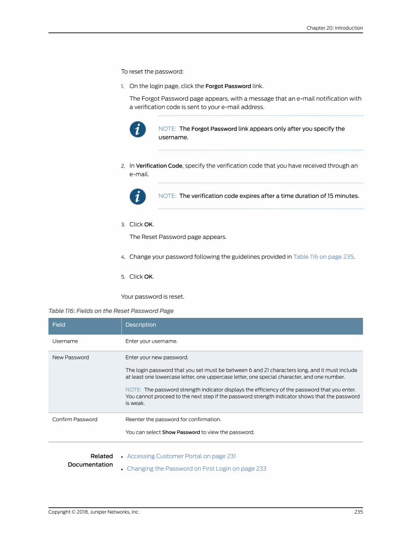
To reset the password:
1. On the login page, click the Forgot Password link.
The Forgot Password page appears, with a message that an e-mail notification with
a verification code is sent to your e-mail address.
NOTE: The Forgot Password link appears only after you specify the
username.
2. In Verification Code, specify the verification code that you have received through an
e-mail.
NOTE: The verification code expires after a time duration of 15minutes.
3. ClickOK.
The Reset Password page appears.
4. Change your password following the guidelines provided in Table 116 on page 235.
5. ClickOK.
Your password is reset.
Table 116: Fields on the Reset Password Page
DescriptionField
Enter your username.Username
Enter your new password.
The login password that you set must be between 6 and 21 characters long, and it must includeat least one lowercase letter, one uppercase letter, one special character, and one number.
NOTE: The password strength indicator displays the efficiency of the password that you enter.You cannot proceed to the next step if the password strength indicator shows that the passwordis weak.
New Password
Reenter the password for confirmation.
You can select ShowPassword to view the password.
Confirm Password
RelatedDocumentation
Accessing Customer Portal on page 231•
• Changing the Password on First Login on page 233
235Copyright © 2018, Juniper Networks, Inc.
Chapter 20: Introduction
• Changing the Customer Portal Password on page 234
Extending the User Login Session
In the unified portal, a login session expires in 60minutes. After 55minutes, the Extend
Session page is displayed and, prompting you to enter your password. Youmust enter
your password to extend the session. The Extend Session page is displayed when the
Local authentication method is configured.
If you have logged in to the portal with SSO authentication, the Extend Session page is
displayed and you can authenticate with the external SSO server. However, the SSO
expiration is not under the control of CSO and the following can happen:
• If the external SSO session is expired, you will be authenticated in the Extend Session
page. After successful authentication, theExtendSessionpage is closedautomatically.
• If the external SSO session is not expired, the Extend Session page is closed
automatically.
To extend the login session:
1. On the Extend Session page, enter your password in the Password field. If you want
toendyour sessionandexit fromtheportal, clickCancel insteadandyouare redirected
to the Login page.
2. ClickOK.
The success message Your Session has been successfully extended is displayed.
RelatedDocumentation
• Changing the Customer Portal Password on page 234
Copyright © 2018, Juniper Networks, Inc.236
Contrail Service Orchestration User Guide
CHAPTER 21
Using the Dashboard
• About the Customer Portal Dashboard on page 237
About the Customer Portal Dashboard
To access the dashboard, select Customer Portal > Dashboard.
Each time you log in to Customer Portal, the first thing you see is a user-configurable
dashboard that offers you a customized view of network services through its widgets.
You can drag these widgets from the top of the dashboard to your workspace, where
you can add, remove, and rearrange them tomeet your needs.
The dashboard automatically adjusts the placement of the widgets to dynamically fit
on your browser windowwithout changing their order. You canmanually reorder the
widgets by using the drag and drop option. In addition, you can press and hold the top
portion of the widget to move it to a new location.
Tasks You Can Perform
You can perform the following tasks from this page:
• Customize the dashboard by adding, removing, and rearranging the widgets on a per
user basis.
• Update the dashboard or an individual widget by clicking the refresh icon.
• Show or hide widget thumbnails by clicking SelectWidgets at the top of the page.
• Add a widget to the dashboard by dragging the widget from the palette or thumbnail
container into the workspace.
• Delete a widget from the dashboard page by clicking the delete icon (X) in the title
bar.
Field Descriptions
You can quickly view important data by using the widgets at the top of your dashboard.
Table 117 on page 238 describes the dashboard widgets.
237Copyright © 2018, Juniper Networks, Inc.
Table 117: Widgets on the Customer Portal Dashboard
DescriptionWidget
View the total number of alerts grouped by severity level.
Click each alert name to view the total number of tenant sites receiving alerts that arecritical, major, or minor.
Alerts Donut Chart
View the top five tenant sites receiving alerts.
• Name—Name of the tenant site.
• Location—Location of the tenant site.
• Status—Type of alerts received: critical, major, or minor.
Top 5 Sites with Alerts
View a bar chart of the top tenant sites that did not meet SLA requirements and thepercentage of time that SLA requirements were not met.
Sort the information based on profile and period ranging from the last hour to the lastmonth.
Top Sites not meeting SLA
View a bar chart of the top SLA profiles that did not meet SLA requirements and thepercentage of time that SLA requirements were not met.
Sort the information based on location and period ranging from the last hour to the lastmonth.
Top Profiles not meeting SLA
View a column chart of the top sites in the tenant that switchedWAN links to meet SLArequirements and the number of link-switch events for the sites.
Sort the information based on profile and period ranging from the last hour to the lastmonth.
Top Sites Switching Links
View a column chart of the top SLA profiles that switchedWAN links and the number oflink-switch events for the SLA profiles.
Sort the information based on location and period ranging from the last hour to the lastmonth.
Top Profiles Switching Links
View a bar chart of the top sites in the tenant that did not meet SLA requirements and thepercentage of time that SLA requirements were not met.
Sort the information based on profile, location, and time period.
Top Applications by Throughput
View a column chart of the top requests denied by the firewall based on their source IPaddresses, sorted by count.
Sort the information based on time period ranging from 5minutes to 7 days.
Firewall: Top Denials
View a bar chart of the top firewall events of the network traffic, sorted by count.
Sort the information based on time period ranging from 5minutes to 7 days.
Firewall: Top Events
View the top IPS events of the network traffic, sorted by count.
Sort the information based on time period ranging from 5minutes to 7 days.
IPS: Top Events
Copyright © 2018, Juniper Networks, Inc.238
Contrail Service Orchestration User Guide
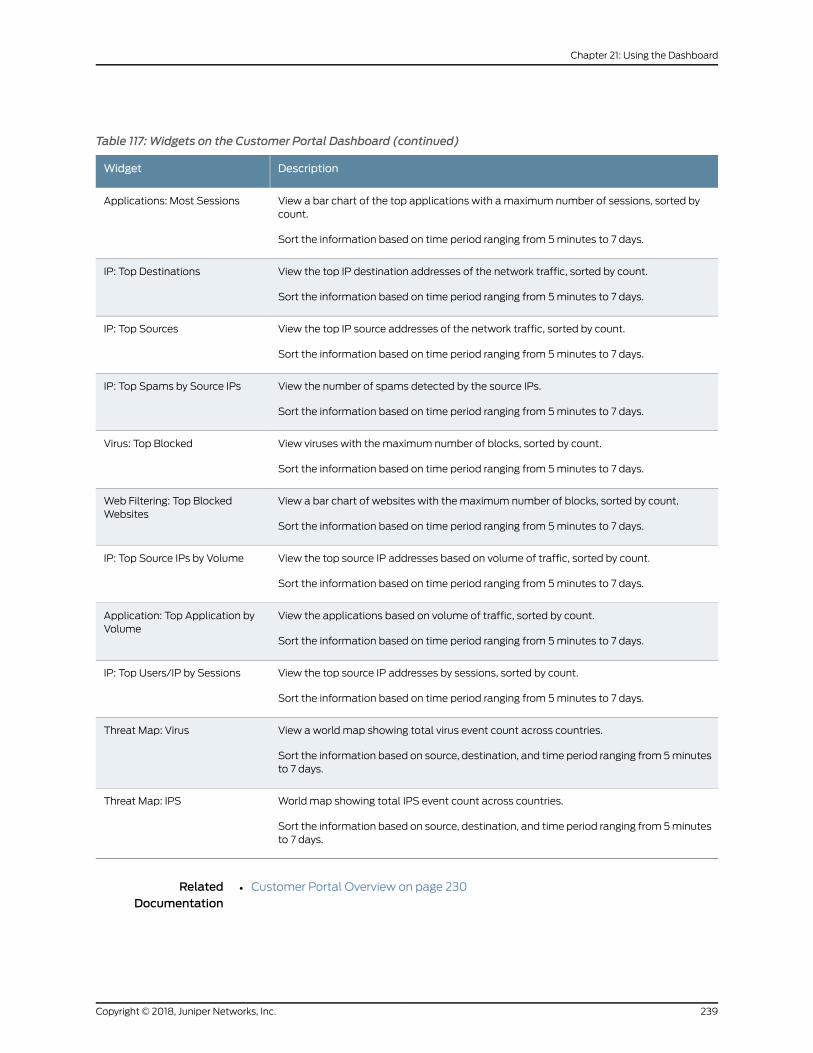
Table 117: Widgets on the Customer Portal Dashboard (continued)
DescriptionWidget
View a bar chart of the top applications with amaximum number of sessions, sorted bycount.
Sort the information based on time period ranging from 5minutes to 7 days.
Applications: Most Sessions
View the top IP destination addresses of the network traffic, sorted by count.
Sort the information based on time period ranging from 5minutes to 7 days.
IP: Top Destinations
View the top IP source addresses of the network traffic, sorted by count.
Sort the information based on time period ranging from 5minutes to 7 days.
IP: Top Sources
View the number of spams detected by the source IPs.
Sort the information based on time period ranging from 5minutes to 7 days.
IP: Top Spams by Source IPs
View viruses with the maximum number of blocks, sorted by count.
Sort the information based on time period ranging from 5minutes to 7 days.
Virus: Top Blocked
View a bar chart of websites with the maximum number of blocks, sorted by count.
Sort the information based on time period ranging from 5minutes to 7 days.
Web Filtering: Top BlockedWebsites
View the top source IP addresses based on volume of traffic, sorted by count.
Sort the information based on time period ranging from 5minutes to 7 days.
IP: Top Source IPs by Volume
View the applications based on volume of traffic, sorted by count.
Sort the information based on time period ranging from 5minutes to 7 days.
Application: Top Application byVolume
View the top source IP addresses by sessions, sorted by count.
Sort the information based on time period ranging from 5minutes to 7 days.
IP: Top Users/IP by Sessions
View a world map showing total virus event count across countries.
Sort the information based on source, destination, and time period ranging from 5minutesto 7 days.
Threat Map: Virus
World map showing total IPS event count across countries.
Sort the information based on source, destination, and time period ranging from 5minutesto 7 days.
Threat Map: IPS
RelatedDocumentation
• Customer Portal Overview on page 230
239Copyright © 2018, Juniper Networks, Inc.
Chapter 21: Using the Dashboard

Copyright © 2018, Juniper Networks, Inc.240
Contrail Service Orchestration User Guide
CHAPTER 22
Managing Objects
• Sorting Objects on page 241
• Viewing Object Details on page 241
• Searching for Text in an Object Data Table on page 242
Sorting Objects
You can use the ShowHideColumns icon in the top right corner of a page to show or hide
objects on a page. You can also sort the objects in a page by clicking the object column.
The following options are available for sorting the objects:
• Sort text in alphabetical order.
• Sort numbers in ascending or descending order.
• Sort by date or time.
• Rearrange columns in a table.
• Increase or decrease columnwidth.
To show or hide an object:
1. Click the ShowHide Columns icon.
The objects that are relevant to the page are displayed. By default all objects are
selected and displayed on the page.
2. Select the objects that need to be displayed on the page and clear the objects that
are not required to be displayed.
The objects are displayed or hidden as per the selection.
RelatedDocumentation
Searching for Text in an Object Data Table on page 242•
Viewing Object Details
You can use the Detailed View page to view all the configured parameters of an object.
Only some of the configured parameters appear in the list of features on themain page.
241Copyright © 2018, Juniper Networks, Inc.
To view details for an object:
• Right-click the object that you want to see the detailed view for and clickQuick View,
or select the object and click More > Details.
• Alternatively, hover over theobject nameandclick theDetailedView icon that appears
before it.
TheDetailedView page appears showing the configuration information. See the relevant
About the Objects Page topic for a description of the fields on these pages.
RelatedDocumentation
Sorting Objects on page 241•
Searching for Text in an Object Data Table
You can use the search icon in the top right corner of a page to search for text containing
letters and special characters on that page.
To search for text:
1. Enter partial text or full text of the keyword in the search bar and click the search icon.
The search results are displayed.
2. Click X next to a search keyword or click Clear All to clear the search results.
RelatedDocumentation
• Sorting Objects on page 241
• Viewing Object Details on page 241
Copyright © 2018, Juniper Networks, Inc.242
Contrail Service Orchestration User Guide
CHAPTER 23
Monitoring Security Alerts and Alarms
• About the Monitor Overview Page on page 243
• Security Alerts Overview on page 244
• About the Generated Alerts Page on page 245
• About the Security Alerts Definitions Page on page 246
• Creating Security Alert Definitions on page 247
• Editing and Deleting Security Alert Definitions on page 248
• Cloning Security Alert Definitions on page 249
About theMonitor Overview Page
To access this page, clickMonitor > Overview.
You can use the Monitor Overview page to view information about the alarms and alerts
for tenants, network services, connections, andsitesonageographicalmap.Thenetwork
operator views the alarms and alerts, and then takes the necessary actions to resolve
the issues.
You can also view the visual representation of the hub and link failure on this page.
• Hub Failure —The hub and the link connected to the hub appear in red color.
• Link Failure — The link connected to the hub appears in red color. However, the hub
remains active and appears in green color.
Tasks You Can Perform
You can perform the following tasks from this page:
• View on-premise spoke site details.
• View on-premise hub site details.
• View cloud spoke sites.
• View cloud hub sites.
• Viewmultiple sites.
243Copyright © 2018, Juniper Networks, Inc.
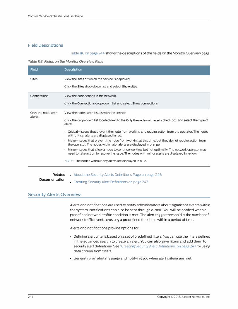
Field Descriptions
Table 118 onpage 244 shows the descriptions of the fields on theMonitorOverviewpage.
Table 118: Fields on theMonitor Overview Page
DescriptionField
View the sites at which the service is deployed.
Click the Sites drop-down list and select Show sites
Sites
View the connections in the network.
Click the Connections drop-down list and select Show connections.
Connections
View the nodes with issues with the service.
Click the drop-down list located next to theOnly the nodeswith alerts check box and select the type ofalerts.
• Critical—Issues that prevent the node fromworking and require action from the operator. The nodeswith critical alerts are displayed in red.
• Major—Issues that prevent the node fromworking at this time, but they do not require action fromthe operator. The nodes with major alerts are displayed in orange.
• Minor—Issues that allow a node to continue working, but not optimally. The network operator mayneed to take action to resolve the issue. The nodes with minor alerts are displayed in yellow.
NOTE: The nodes without any alerts are displayed in blue.
Only the node withalerts
RelatedDocumentation
About the Security Alerts Definitions Page on page 246•
• Creating Security Alert Definitions on page 247
Security Alerts Overview
Alerts and notifications are used to notify administrators about significant events within
the system. Notifications can also be sent through e-mail. You will be notified when a
predefined network traffic condition is met. The alert trigger threshold is the number of
network traffic events crossing a predefined threshold within a period of time.
Alerts and notifications provide options for:
• Definingalert criteria basedona set of predefined filters. You canuse the filters defined
in the advanced search to create an alert. You can also save filters and add them to
security alert definitions. See “CreatingSecurity Alert Definitions” onpage 247 for using
data criteria from filters.
• Generating an alert message and notifying you when alert criteria are met.
Copyright © 2018, Juniper Networks, Inc.244
Contrail Service Orchestration User Guide
• Searching for specific alerts on theGeneratedAlerts pagebasedonalert ID, description,
or alert type.
• Supporting event-based alerts.
For example, If you are an administrator, you can define a condition such that if the
number of firewall-deny events crosses a predefined threshold in a given time range for
a specific device, you will receive an e-mail alert.
NOTE: If a threshold is crossedand remains so for a longduration, newalertsare not generated. Alerts are generated again when the number of logsmatching the alert criteria drops below the threshold and crosses thethreshold again.
RelatedDocumentation
About the Security Alerts Definitions Page on page 246•
• Creating Security Alert Definitions on page 247
About the Generated Alerts Page
To access this page, clickMonitor > Alerts & Alarms > Alerts.
Use this page to view the system event-based alerts in response to a configured alert
definition. The generated alerts help you to identify problems that appear in your
monitored network environment anddisplays both security andCSOalerts. You can view
statistics such as the number of critical and non-critical alerts.
Tasks You Can Perform
You can perform the following tasks from this page:
• Select the generated alert and then right-click or clickMore > Jump to Events and Logs.
The corresponding events that triggered the alert are displayed.
• Select the generated alert and then right-click or clickMore > Detail View.
• Select the generated alert and then right-click or clickMore > Clear All Selections.
Field Descriptions
Table 119onpage245providesguidelinesonusing the fieldson theGeneratedAlertspage.
Table 119: Fields on the Generated Alerts Page
DescriptionField
View the date and time when the alert was generated.Time
View the name of the alert.Alert Name
View the description of the alert.Alert Description
245Copyright © 2018, Juniper Networks, Inc.
Chapter 23: Monitoring Security Alerts and Alarms
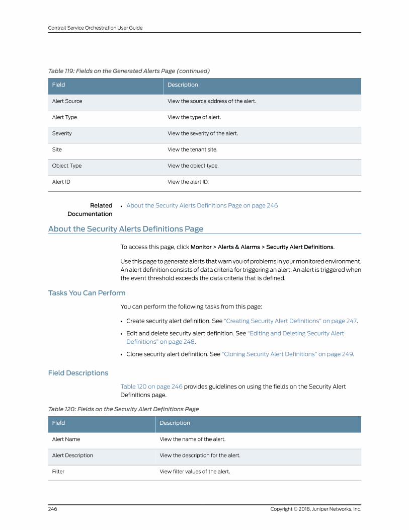
Table 119: Fields on the Generated Alerts Page (continued)
DescriptionField
View the source address of the alert.Alert Source
View the type of alert.Alert Type
View the severity of the alert.Severity
View the tenant site.Site
View the object type.Object Type
View the alert ID.Alert ID
RelatedDocumentation
About the Security Alerts Definitions Page on page 246•
About the Security Alerts Definitions Page
To access this page, clickMonitor > Alerts & Alarms > Security Alert Definitions.
Use thispage togeneratealerts thatwarnyouofproblems in yourmonitoredenvironment.
Analert definitionconsistsofdatacriteria for triggeringanalert. Analert is triggeredwhen
the event threshold exceeds the data criteria that is defined.
Tasks You Can Perform
You can perform the following tasks from this page:
• Create security alert definition. See “Creating Security Alert Definitions” on page 247.
• Edit and delete security alert definition. See “Editing and Deleting Security Alert
Definitions” on page 248.
• Clone security alert definition. See “Cloning Security Alert Definitions” on page 249.
Field Descriptions
Table 120 on page 246 provides guidelines on using the fields on the Security Alert
Definitions page.
Table 120: Fields on the Security Alert Definitions Page
DescriptionField
View the name of the alert.Alert Name
View the description for the alert.Alert Description
View filter values of the alert.Filter
Copyright © 2018, Juniper Networks, Inc.246
Contrail Service Orchestration User Guide
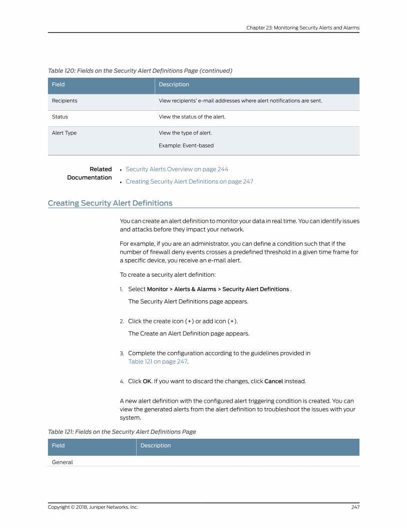
Table 120: Fields on the Security Alert Definitions Page (continued)
DescriptionField
View recipients’ e-mail addresses where alert notifications are sent.Recipients
View the status of the alert.Status
View the type of alert.
Example: Event-based
Alert Type
RelatedDocumentation
Security Alerts Overview on page 244•
• Creating Security Alert Definitions on page 247
Creating Security Alert Definitions
You can create analert definition tomonitor your data in real time. You can identify issues
and attacks before they impact your network.
For example, if you are an administrator, you can define a condition such that if the
number of firewall deny events crosses a predefined threshold in a given time frame for
a specific device, you receive an e-mail alert.
To create a security alert definition:
1. SelectMonitor > Alerts & Alarms > Security Alert Definitions .
The Security Alert Definitions page appears.
2. Click the create icon (+) or add icon (+).
The Create an Alert Definition page appears.
3. Complete the configuration according to the guidelines provided in
Table 121 on page 247.
4. ClickOK. If you want to discard the changes, click Cancel instead.
A new alert definition with the configured alert triggering condition is created. You can
view the generated alerts from the alert definition to troubleshoot the issues with your
system.
Table 121: Fields on the Security Alert Definitions Page
DescriptionField
General
247Copyright © 2018, Juniper Networks, Inc.
Chapter 23: Monitoring Security Alerts and Alarms
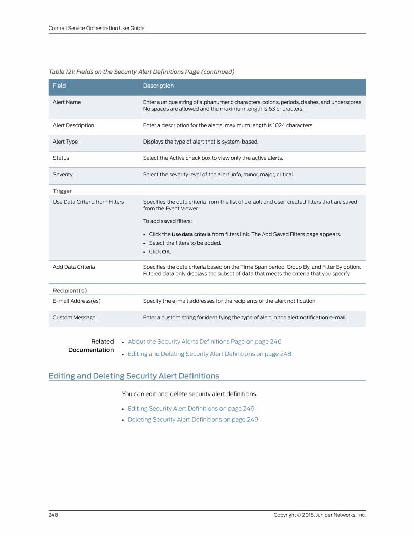
Table 121: Fields on the Security Alert Definitions Page (continued)
DescriptionField
Enter aunique stringof alphanumeric characters, colons, periods, dashes, andunderscores.No spaces are allowed and themaximum length is 63 characters.
Alert Name
Enter a description for the alerts; maximum length is 1024 characters.Alert Description
Displays the type of alert that is system-based.Alert Type
Select the Active check box to view only the active alerts.Status
Select the severity level of the alert: info, minor, major, critical.Severity
Trigger
Specifies the data criteria from the list of default and user-created filters that are savedfrom the Event Viewer.
To add saved filters:
• Click the Use data criteria from filters link. The Add Saved Filters page appears.
• Select the filters to be added.
• ClickOK.
Use Data Criteria from Filters
Specifies the data criteria based on the Time Span period, Group By, and Filter By option.Filtered data only displays the subset of data that meets the criteria that you specify.
Add Data Criteria
Recipient(s)
Specify the e-mail addresses for the recipients of the alert notification.E-mail Address(es)
Enter a custom string for identifying the type of alert in the alert notification e-mail.CustomMessage
RelatedDocumentation
About the Security Alerts Definitions Page on page 246•
• Editing and Deleting Security Alert Definitions on page 248
Editing and Deleting Security Alert Definitions
You can edit and delete security alert definitions.
• Editing Security Alert Definitions on page 249
• Deleting Security Alert Definitions on page 249
Copyright © 2018, Juniper Networks, Inc.248
Contrail Service Orchestration User Guide
Editing Security Alert Definitions
To edit the security alert definition:
1. SelectMonitor > Alerts & Alarms > Security Alert Definitions.
The Security Alerts Definition page appears.
2. Select the check box of the security alert definition that youwant tomodify, and click
the edit icon.
The Edit Alert Definition page appears. The options available on the Create Alert
Definition page are available for editing.
3. Update the configuration as needed.
4. ClickOK to save the changes. If youwant todiscard your changes, clickCancel instead.
Deleting Security Alert Definitions
You can click the delete icon (X) to delete one or more alert definitions.
To delete the alert definition:
1. SelectMonitor > Alerts & Alarms > Security Alerts.
The Security Alerts Definition page appears.
2. Select the alert definition that you want to delete and click the delete icon (X icon).
The Confirm Delete page appears.
3. Click Yes to delete the alert definition or No to cancel the deletion.
If you click Yes, then the alert definition is deleted from themain page.
RelatedDocumentation
About the Security Alerts Definitions Page on page 246•
• Creating Security Alert Definitions on page 247
Cloning Security Alert Definitions
You can clone an alert definition when you want to quickly create a copy of an alert
definition andmodify its parameters including the name of the alert.
To clone an alert definition:
1. SelectMonitor > Alerts & Alarms > Security Alert Definition.
The Security Alert Definitions page appears.
249Copyright © 2018, Juniper Networks, Inc.
Chapter 23: Monitoring Security Alerts and Alarms
2. Select the alert definition that you want to clone, and clickMore > Clone at the top
right corner of the page.
The Clone Alert Definition page appears.
3. ClickOK to save the configuration.
A new alert definition is created.
RelatedDocumentation
• About the Security Alerts Definitions Page on page 246
• Creating Security Alert Definitions on page 247
Copyright © 2018, Juniper Networks, Inc.250
Contrail Service Orchestration User Guide
CHAPTER 24
Monitoring Security and Device Events
• About the All Security Events Page on page 251
• About the Firewall Events Page on page 255
• About theWeb Filtering Events Page on page 258
• About the IPsec VPNs Events Page on page 260
• About the Content Filtering Events Page on page 262
• About the Antispam Events Page on page 264
• About the Antivirus Events Page on page 266
• About the IPS Events Page on page 268
• About the Device Events Page on page 271
• About the Screen Events Page on page 275
About the All Security Events Page
To access this page, clickMonitoring > Security Events > All Events.
Use this page to get an overall, high level view of your network environment. You can
viewabnormalevents, attacks, viruses, orwormswhen logdata is correlatedandanalyzed.
This page provides administrators with an advanced filtering mechanism and provides
visibility into actual events collected by the Log Collector. Using the time-range slider,
you can instantly focus on areas of unusual activity by dragging the time slider to the
area of interest to you. The slider and the Custom button under Time Range remain at
the top of each tab. Users select the time range, and then they can decide how to view
the data, using the summary view or detail view tabs.
Tasks You Can Perform
You can perform the following tasks from this page:
• View a brief summary of all events in your network. See “Summary View” on page 252.
• View the comprehensive details of events in a tabular format that includes sortable
columns. See “Detail View” on page 252.
251Copyright © 2018, Juniper Networks, Inc.
Summary View
You can view a brief summary of all the events in your network. At the center of the page
is critical information, including total number of events, viruses found, total number of
interfaces that are down, number of attacks, CPU spikes, and system reboots. This data
is refreshed automatically based on the selected time range. At the bottom of the page
is a swim lane view of different events that are happening at a specific time. The events
include firewall, web filtering, VPN, content filtering, antispam, antivirus, and IPS. Each
event is color coded, with darker shades representing a higher level of activity. Each tab
providesdeep information like type, andnumber of events occurring at that specific time.
Table 122 on page 252 describes the widgets on the All Events Summary View page.
Table 122: Widgets on the All Events Summary View Page
DescriptionField
View the total number of all the events that includes firewall, web filtering, IPS, IPSecVPNs, content filtering, antispam, and antivirus events.
Total Events
View the total number of virtual instances running in the system.Virus Instances
View the total number of attacks on the firewall.Attacks
View the total number of interfaces that are down.Interface Down
View the total number of times a CPU utilization spike has occurred.CPU Spikes
View the total number of system reboots.Reboots
View the total number of sessions established through firewall.Sessions
Detail View
Click Detail View for comprehensive details of events in a tabular format that includes
sortable columns. You can sort the events using the Group By option. For example, you
can sort the events based on severity. The table includes information such as the rule
that caused the event, severity for the event, event ID, traffic information, and how and
when the event was detected.
Advanced Search
You can perform advanced search of all events using the text field present above the
tabular column. It includes the logical operators as part of the filter string. Enter the
search string in the text field andbasedon your input, a list of items from the filter context
menu is displayed. . You can select a value from the list and then select a valid logical
operator to perform the advanced search operation Press Enter to display the search
result in the tabular column below.
To delete the search string in the text field, click the delete icon (X icon).
Copyright © 2018, Juniper Networks, Inc.252
Contrail Service Orchestration User Guide
Examples of event log filters are shown in the following list:
• Specific events originating from or landing within United States
Source Country = United States OR Destination Country = United States AND Event
Name = IDP_ATTACK_LOG_EVENT, IDP_ATTACK_LOG_EVENT_LS,
IDP_APPDDOS_APP_ATTACK_EVENT_LS, IDP_APPDDOS_APP_STATE_EVENT,
IDP_APPDDOS_APP_STATE_EVENT_LS, AV_VIRUS_DETECTED_MT,
AV_VIRUS_DETECTED, ANTISPAM_SPAM_DETECTED_MT,
ANTISPAM_SPAM_DETECTED_MT_LS, FWAUTH_FTP_USER_AUTH_FAIL,
FWAUTH_FTP_USER_AUTH_FAIL_LS, FWAUTH_HTTP_USER_AUTH_FAIL,
FWAUTH_HTTP_USER_AUTH_FAIL_LS, FWAUTH_TELNET_USER_AUTH_FAIL,
FWAUTH_TELNET_USER_AUTH_FAIL_LS,
FWAUTH_WEBAUTH_FAIL,FWAUTH_WEBAUTH_FAIL_LS
• User wants to filter all RT flow sessions originating from IP addresses in specific
countries and landing on IPs in specific countries
EventName=RT_FLOW_SESSION_CREATE,RT_FLOW_SESSION_CLOSEANDSource
IP = 177.1.1.1,220.194.0.150,14.1.1.2,196.194.56.4 AND Destination IP =
255.255.255.255,10.207.99.75,10.207.99.72,223.165.27.13 AND Source Country = Brazil,
UnitedStates,China,Russia,AlgeriaANDDestinationCountry=Germany, India,United
States
• Traffic between zone pairs for policy – IDP2
Source Zone= trust ANDDestination Zone= untrust, internal ANDPolicy Name= IDP2
• UTMlogscoming fromspecific sourcecountry, destinationcountry, source IPaddresses
with or without specific destination IP addresses.
Event Category = antispam, antivirus, contentfilter, webfilter AND Source Country =
Australia AND Destination Country = Turkey, United States, Australia AND Source IP
= 1.0.0.0,1.1.1.3 OR Destination IP = 74.125.224.47,5.56.17.61
• Events with specific sources IPs or events hitting HTP, FTP, HTTP, and unknown
applications coming from host DC-SRX1400-1 or VSRX-75.
Application = tftp, ftp, http, unknown OR Source IP = 192.168.34.10,192.168.1.26 AND
Hostname = dc-srx1400-1,vsrx-75
Table 123 on page 253 describes the fields on the All Events Detail View Page.
Table 123: Fields on the All Events Detail View Page
DescriptionField
View the time when the log was received.Time
View the event name of the log.Event Name
View the name of the tenant site.Site
View the source country name.Source Country
253Copyright © 2018, Juniper Networks, Inc.
Chapter 24: Monitoring Security and Device Events
Table 123: Fields on the All Events Detail View Page (continued)
DescriptionField
View the source IP address fromwhere the event occurred.Source IP
View the destination country name fromwhere the event occurred.Destination Country
View the destination IP address of the event.Destination IP
View the source port of the event.Source Port
View the destination port of the event.Destination Port
View the description of the log.Description
View the attack name of the log: Trojan, worm, virus, and so on.Attack Name
View the severity level of the threat.Threat Severity
View the policy name in the log.Policy Name
View the UTM category of the log.UTM Category or Virus Name
View the accessed URL name that triggered the event.URL
View the event category of the log.Event Category
View the username of the log.User Name
View the action taken for the event: warning, allow, and block.Action
View the IP address of the log source.Log Source
View the application name fromwhich the events or logs are generatedApplication
View the hostname in the log.Hostname
The name of the application service. For example, FTP, HTTP, SSH, and so on.Service Name
View the nested application in the log.Nested Application
View the source zone of the log.Source Zone
View the destination zone of the log.Destination Zone
View the protocol ID in the log.Protocol ID
View the role name associated with the log.Roles
Copyright © 2018, Juniper Networks, Inc.254
Contrail Service Orchestration User Guide
Table 123: Fields on the All Events Detail View Page (continued)
DescriptionField
View the reason for the log generation. For example, a connection tear downmayhave an associated reason such as “authentication failed”.
Reason
View the translated source port.NAT Source Port
View the translated destination port.NAT Destination Port
View the NAT source rule name.NAT Source Rule Name
View the NAT destination rule name.NAT Destination Rule Name
View the translated (or natted) source IP address. It can contain IPv4 or IPv6addresses.
NAT Source IP
View the translated (also called natted) destination IP address.NAT Destination IP
View the traffic session ID of the log.Traffic Session ID
View the path name of the log.Path Name
View the name of the logical system.Logical system Name
View the name of the rule.Rule Name
View the name of the All events profile that triggered the event.Profile Name
RelatedDocumentation
About the Firewall Events Page on page 255•
• About theWeb Filtering Events Page on page 258
• About the IPsec VPNs Events Page on page 260
• About the Content Filtering Events Page on page 262
• About the Antispam Events Page on page 264
• About the Antivirus Events Page on page 266
• About the IPS Events Page on page 268
About the Firewall Events Page
To access this page, clickMonitor > Security Events > Firewall.
Use the Firewall Events page to view information about security events based on firewall
policies. Analyzing firewall logs yields useful security management information, such as
attempts tobreachyournetworkandobserving the inherent characteristicsof your traffic
in real-time. Using the time-range slider, you can quickly focus on the area of activity that
255Copyright © 2018, Juniper Networks, Inc.
Chapter 24: Monitoring Security and Device Events
you are most interested in. Once the time range is selected, all of the data presented in
your view is refreshedautomatically. You canalso use theCustombutton to set a custom
time range.
There are two ways to view your data. You can select either the Summary View tab or
the Detail View tab.
Tasks You Can Perform
You can perform the following tasks from this page:
• View a brief summary of all the firewall events in your network. See “Summary View”
on page 256
• View the comprehensive details of events in a tabular format that includes sortable
columns. See “Detail View” on page 256.
Summary View
The data presented in the line graph (also known as swim lanes) is refreshed
automatically based on the selected time range. The line graph shows light blue lanes
that represent all firewall events and dark blue lanes represent blocked firewall events.
Below the swim lanes are widgets displaying critical information such as top sources,
top destinations, top users, and top reporting devices.
Table 124 on page 256 describes the widgets on the Summary View page.
Table 124:Widgets on the Summary View Page
DescriptionWidget
View the top source IP addresses of the network traffic; sorted by event count.Top Sources
View the top destination IP addresses of the network traffic; sorted by event count.Top Destinations
View then top users of the network traffic; sorted by event count.Top Users
View the top reporting devices in the network; sorted by event count.Top Reporting Devices
Detail View
Detail view includes information such as the rule that caused the event, severity for the
event, event ID, traffic information, and how and when the event was detected
Table 125 on page 256 provides guidelines on using the fields on the Detail View page.
Table 125: Fields on the Detail View Page
DescriptionField
View the time when the log was received.Time
Copyright © 2018, Juniper Networks, Inc.256
Contrail Service Orchestration User Guide
Table 125: Fields on the Detail View Page (continued)
DescriptionField
View the event name of the log.Event Name
View the source country name fromwhere the event originated.Source Country
View the source IP address fromwhere the event occurred.Source IP
View the destination country name fromwhere the event occurred.Destination Country
View the destination IP address of the event.Destination IP
View the source port of the event.Source Port
View the destination port of the event.Destination Port
View the description of the log.Description
View the policy name in the log.Policy Name
View the username of the log.User Name
View the action taken for the event: warning, allow, and block.Action
View the IP address of the log source (IPv4 or IPv6).Log Source
View the application name fromwhich the events or logs are generated.Application
View the hostname in the log.Hostname
The name of the application service. For example, FTP, HTTP, SSH, and so on.Service Name
View the nested application in the log.Nested Application
View the user traffic received from the zone.Source Zone
View the destination zone of the log.Destination Zone
View the protocol ID in the log.Protocol ID
View the role names associated with the event.Roles
View the translated source port.NAT Source Port
View the translated destination port.NAT Destination Port
View the NAT source rule name.NAT Source Rule Name
View the NAT destination rule name.NAT Destination Rule Name
257Copyright © 2018, Juniper Networks, Inc.
Chapter 24: Monitoring Security and Device Events
Table 125: Fields on the Detail View Page (continued)
DescriptionField
View the translated (or natted) source IP address. It can contain IPv4 or IPv6addresses.
NAT Source IP
View the translated (also called natted) destination IP address.NAT Destination IP
View the traffic session ID of the log.Traffic Session ID
View the rule name of the log.Rule Name
RelatedDocumentation
About the All Security Events Page on page 251•
• About theWeb Filtering Events Page on page 258
• About the IPsec VPNs Events Page on page 260
• About the Content Filtering Events Page on page 262
• About the Antispam Events Page on page 264
• About the Antivirus Events Page on page 266
• About the IPS Events Page on page 268
About theWeb Filtering Events Page
To access this page, clickMonitor > Security Events >Web Filtering.
Use theWeb Filtering page to view information about security events based onWeb
filtering policies. Web filtering allows you to permit or block access to specific websites
by URL or by URL category using cloud-based lookups, a local database, or an external
Websense server. AnalyzingWeb filtering logs yields useful security management
information such as users detected accessing restricted URLs and actions taken by the
system. Using the time-range slider, you can quickly focus on the area of activity that you
are most interested in. Once the time range is selected, all of the data presented in your
view is refreshed automatically. You can also use the Custom button to set a custom
time range.
There are two ways to view your data. You can select either the Summary View tab or
the Detail View tab.
Tasks You Can Perform
You can perform the following tasks from this page:
• View a brief summary of all theWeb filtering events in your network. See “Summary
View” on page 259.
• View the comprehensive details of events in a tabular format that includes sortable
columns. See “Detail View” on page 259.
Copyright © 2018, Juniper Networks, Inc.258
Contrail Service Orchestration User Guide
Summary View
The top of the page has a swim lane graph of all theWeb filtering events against the
blocked events.
Below the swim lanes are widgets displaying critical information such as top sources,
top destinations, top users, and top reporting devices.
You can use the widgets at the bottom of the page to view critical information such as
top URLs blocked, topmatched profiles, top sources, and top destinations.
Table 126 on page 259 describes the widgets on the Summary View page.
Table 126:Widgets on the Summary View Page
DescriptionWidget
View the URL names that are blocked; sorted by event count.Top URLs blocked
View the web filtering profile names; sorted by event count.Top Matched Profiles
View the top source IP addresses of the network traffic; sorted by event count.Top Sources
View the top destination IP addresses of the network traffic; sorted by event count.Top Destinations
Detail View
You can aggregate the events using the Group By option. For example, you can group
the events based on source country. The table includes information such as the event
name, UTM category, source IP address, source country, and so on.
Table 127 on page 259 provides guidelines on using the fields on the Detail View page.
Table 127: Fields on the Detail View Page
DescriptionFields
View the time when the event occurred.Time
View the event name of the log.Event Name
View the source country name fromwhere the event originated.Source Country
View the source IP address fromwhere the event occurred (IPv4 or IPv6).Source IP
View the destination country name fromwhere the event occurred.Destination Country
View the destination IP address of the event (IPv4 or IPv6).Destination IP
View the source port of the event.Source Port
View the destination port of the event.Destination Port
259Copyright © 2018, Juniper Networks, Inc.
Chapter 24: Monitoring Security and Device Events
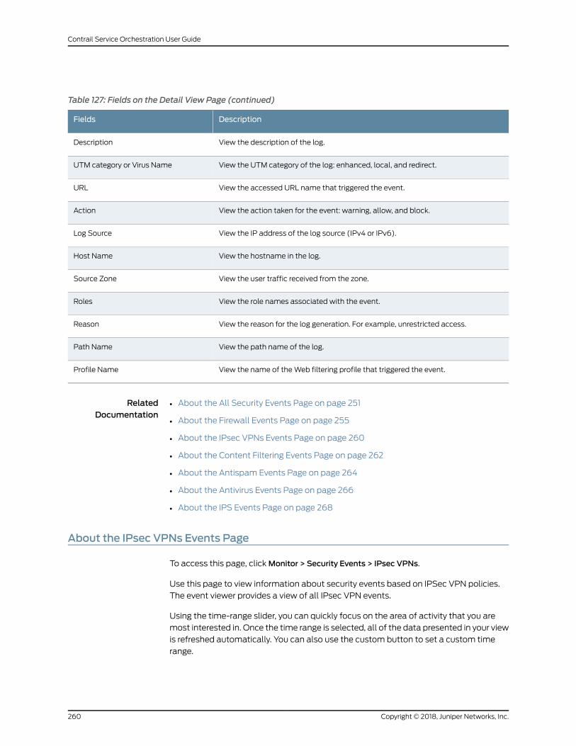
Table 127: Fields on the Detail View Page (continued)
DescriptionFields
View the description of the log.Description
View the UTM category of the log: enhanced, local, and redirect.UTM category or Virus Name
View the accessed URL name that triggered the event.URL
View the action taken for the event: warning, allow, and block.Action
View the IP address of the log source (IPv4 or IPv6).Log Source
View the hostname in the log.Host Name
View the user traffic received from the zone.Source Zone
View the role names associated with the event.Roles
View the reason for the log generation. For example, unrestricted access.Reason
View the path name of the log.Path Name
View the name of theWeb filtering profile that triggered the event.Profile Name
RelatedDocumentation
About the All Security Events Page on page 251•
• About the Firewall Events Page on page 255
• About the IPsec VPNs Events Page on page 260
• About the Content Filtering Events Page on page 262
• About the Antispam Events Page on page 264
• About the Antivirus Events Page on page 266
• About the IPS Events Page on page 268
About the IPsec VPNs Events Page
To access this page, clickMonitor > Security Events > IPsec VPNs.
Use this page to view information about security events based on IPSec VPN policies.
The event viewer provides a view of all IPsec VPN events.
Using the time-range slider, you can quickly focus on the area of activity that you are
most interested in. Once the time range is selected, all of the data presented in your view
is refreshed automatically. You can also use the custom button to set a custom time
range.
Copyright © 2018, Juniper Networks, Inc.260
Contrail Service Orchestration User Guide
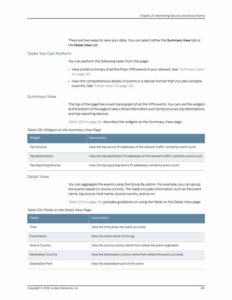
There are two ways to view your data. You can select either the Summary View tab or
the Detail View tab.
Tasks You Can Perform
You can perform the following tasks from this page:
• Viewabrief summaryofall the IPsecVPNevents in yournetwork.See “SummaryView”
on page 261.
• View the comprehensive details of events in a tabular format that includes sortable
columns. See “Detail View” on page 261.
Summary View
The topof the page has a swim lane graphof all theVPNevents. You can use thewidgets
at thebottomof thepage toviewcritical informationsuchas topsources, topdestinations,
and top reporting devices.
Table 128 on page 261 describes the widgets on the Summary View page.
Table 128:Widgets on the Summary View Page
DescriptionWidget
View the top source IP addresses of the network traffic; sorted by event count.Top Sources
View the top destination IP addresses of the network traffic; sorted by event count.Top Destinations
View the top reporting device IP addresses; sorted by event count.Top Reporting Devices
Detail View
You can aggregate the events using the Group By option. For example, you can group
the events based on source country. The table includes information such as the event
name, log source, host name, source country, and so on.
Table 129 on page 261 provides guidelines on using the fields on the Detail View page.
Table 129: Fields on the Detail View Page
DescriptionFields
View the time when the event occurred.Time
View the event name of the log.Event Name
View the source country name fromwhere the event originated.Source Country
View the destination country name fromwhere the event occurred.Destination Country
View the destination port of the event.Destination Port
261Copyright © 2018, Juniper Networks, Inc.
Chapter 24: Monitoring Security and Device Events
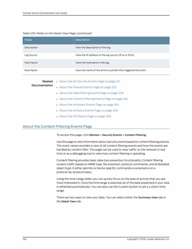
Table 129: Fields on the Detail View Page (continued)
DescriptionFields
View the description of the log.Description
View the IP address of the log source (IPv4 or IPv6).Log Source
View the hostname in the log.Host Name
View the name of the antivirus profile that triggered the event.Rule Name
RelatedDocumentation
About the All Security Events Page on page 251•
• About the Firewall Events Page on page 255
• About theWeb Filtering Events Page on page 258
• About the Content Filtering Events Page on page 262
• About the Antispam Events Page on page 264
• About the Antivirus Events Page on page 266
• About the IPS Events Page on page 268
About the Content Filtering Events Page
To access this page, clickMonitor > Security Events > Content Filtering.
Use thispage toview informationabout security eventsbasedoncontent filteringpolicies.
The event viewer provides a view of all content filtering events and how the events are
handled by content filter. This page can be used to view traffic on the network in real
time or as a debugging tool to view how content filtering is operating.
Content filtering provides basic data loss prevention functionality. Content filtering
screens traffic based on MIME type, file extension, protocol commands, and embedded
object type. It either permits or blocks specific commands or extensions on a
protocol-by-protocol basis.
Using the time-range slider, you can quickly focus on the area of activity that you are
most interested in. Once the time range is selected, all of the data presented in your view
is refreshed automatically. You can also use the Custom button to set a custom time
range.
There are two ways to view your data. You can select either the Summary View tab or
the Detail View tab.
Copyright © 2018, Juniper Networks, Inc.262
Contrail Service Orchestration User Guide
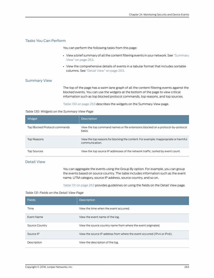
Tasks You Can Perform
You can perform the following tasks from this page:
• Viewabrief summary of all the content filtering events in your network. See “Summary
View” on page 263.
• View the comprehensive details of events in a tabular format that includes sortable
columns. See “Detail View” on page 263.
Summary View
The top of the page has a swim lane graph of all the content filtering events against the
blocked events. You can use the widgets at the bottom of the page to view critical
information such as top blocked protocol commands, top reasons, and top sources.
Table 130 on page 263 describes the widgets on the Summary View page.
Table 130:Widgets on the Summary View Page
DescriptionWidget
View the top command names or file extensions blocked on a protocol-by-protocolbasis.
Top Blocked Protocol commands
View the top reasons for blocking the content. For example: Inappropriate or harmfulcommunication.
Top Reasons
View the top source IP addresses of the network traffic; sorted by event count.Top Sources
Detail View
You can aggregate the events using the Group By option. For example, you can group
the events based on source country. The table includes information such as the event
name, UTM category, source IP address, source country, and so on.
Table 131 on page 263 provides guidelines on using the fields on the Detail View page.
Table 131: Fields on the Detail View Page
DescriptionFields
View the time when the event occurred.Time
View the event name of the log.Event Name
View the source country name fromwhere the event originated.Source Country
View the source IP address fromwhere the event occurred (IPv4 or IPv6).Source IP
View the description of the log.Description
263Copyright © 2018, Juniper Networks, Inc.
Chapter 24: Monitoring Security and Device Events
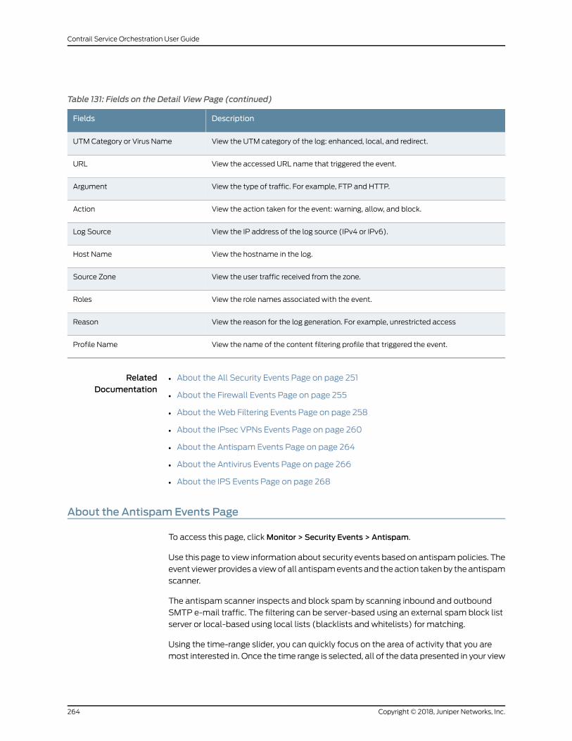
Table 131: Fields on the Detail View Page (continued)
DescriptionFields
View the UTM category of the log: enhanced, local, and redirect.UTM Category or Virus Name
View the accessed URL name that triggered the event.URL
View the type of traffic. For example, FTP and HTTP.Argument
View the action taken for the event: warning, allow, and block.Action
View the IP address of the log source (IPv4 or IPv6).Log Source
View the hostname in the log.Host Name
View the user traffic received from the zone.Source Zone
View the role names associated with the event.Roles
View the reason for the log generation. For example, unrestricted accessReason
View the name of the content filtering profile that triggered the event.Profile Name
RelatedDocumentation
About the All Security Events Page on page 251•
• About the Firewall Events Page on page 255
• About theWeb Filtering Events Page on page 258
• About the IPsec VPNs Events Page on page 260
• About the Antispam Events Page on page 264
• About the Antivirus Events Page on page 266
• About the IPS Events Page on page 268
About the Antispam Events Page
To access this page, clickMonitor > Security Events > Antispam.
Use this page to view information about security events based on antispampolicies. The
event viewer providesa viewof all antispamevents and theaction takenby theantispam
scanner.
The antispam scanner inspects and block spam by scanning inbound and outbound
SMTP e-mail traffic. The filtering can be server-based using an external spam block list
server or local-based using local lists (blacklists and whitelists) for matching.
Using the time-range slider, you can quickly focus on the area of activity that you are
most interested in. Once the time range is selected, all of the data presented in your view
Copyright © 2018, Juniper Networks, Inc.264
Contrail Service Orchestration User Guide
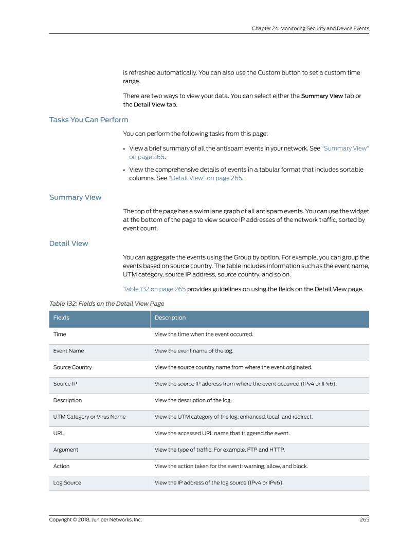
is refreshed automatically. You can also use the Custom button to set a custom time
range.
There are two ways to view your data. You can select either the Summary View tab or
the Detail View tab.
Tasks You Can Perform
You can perform the following tasks from this page:
• Viewabrief summary of all the antispamevents in your network. See “SummaryView”
on page 265.
• View the comprehensive details of events in a tabular format that includes sortable
columns. See “Detail View” on page 265.
Summary View
The topof thepagehasa swim lanegraphof all antispamevents. You canuse thewidget
at the bottom of the page to view source IP addresses of the network traffic, sorted by
event count.
Detail View
You can aggregate the events using the Group by option. For example, you can group the
events based on source country. The table includes information such as the event name,
UTM category, source IP address, source country, and so on.
Table 132 on page 265 provides guidelines on using the fields on the Detail View page.
Table 132: Fields on the Detail View Page
DescriptionFields
View the time when the event occurred.Time
View the event name of the log.Event Name
View the source country name fromwhere the event originated.Source Country
View the source IP address fromwhere the event occurred (IPv4 or IPv6).Source IP
View the description of the log.Description
View the UTM category of the log: enhanced, local, and redirect.UTM Category or Virus Name
View the accessed URL name that triggered the event.URL
View the type of traffic. For example, FTP and HTTP.Argument
View the action taken for the event: warning, allow, and block.Action
View the IP address of the log source (IPv4 or IPv6).Log Source
265Copyright © 2018, Juniper Networks, Inc.
Chapter 24: Monitoring Security and Device Events
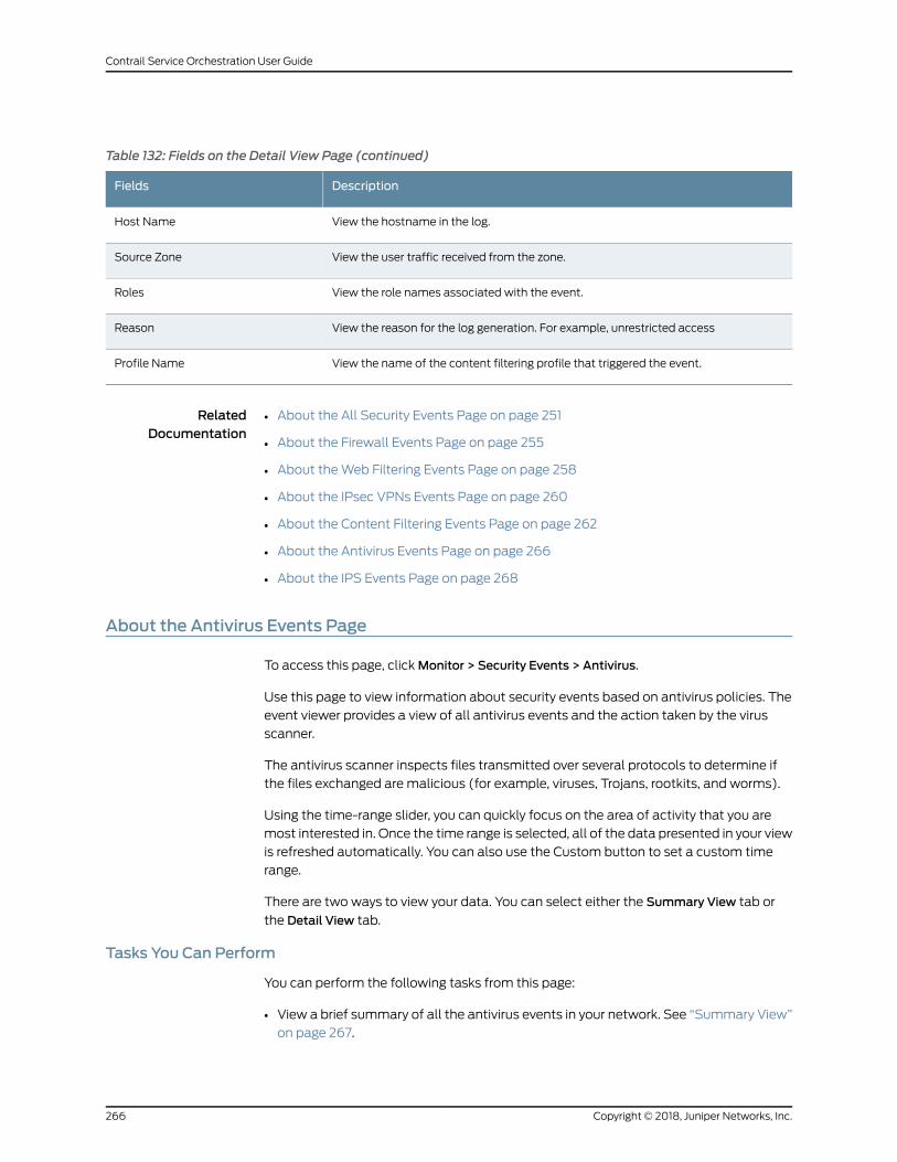
Table 132: Fields on the Detail View Page (continued)
DescriptionFields
View the hostname in the log.Host Name
View the user traffic received from the zone.Source Zone
View the role names associated with the event.Roles
View the reason for the log generation. For example, unrestricted accessReason
View the name of the content filtering profile that triggered the event.Profile Name
RelatedDocumentation
About the All Security Events Page on page 251•
• About the Firewall Events Page on page 255
• About theWeb Filtering Events Page on page 258
• About the IPsec VPNs Events Page on page 260
• About the Content Filtering Events Page on page 262
• About the Antivirus Events Page on page 266
• About the IPS Events Page on page 268
About the Antivirus Events Page
To access this page, clickMonitor > Security Events > Antivirus.
Use this page to view information about security events based on antivirus policies. The
event viewer provides a view of all antivirus events and the action taken by the virus
scanner.
The antivirus scanner inspects files transmitted over several protocols to determine if
the files exchanged are malicious (for example, viruses, Trojans, rootkits, and worms).
Using the time-range slider, you can quickly focus on the area of activity that you are
most interested in. Once the time range is selected, all of the data presented in your view
is refreshed automatically. You can also use the Custom button to set a custom time
range.
There are two ways to view your data. You can select either the Summary View tab or
the Detail View tab.
Tasks You Can Perform
You can perform the following tasks from this page:
• View a brief summary of all the antivirus events in your network. See “Summary View”
on page 267.
Copyright © 2018, Juniper Networks, Inc.266
Contrail Service Orchestration User Guide
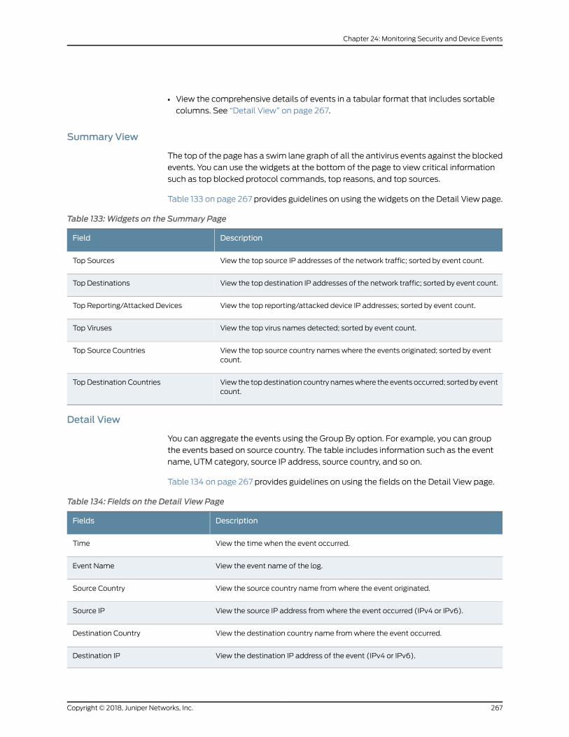
• View the comprehensive details of events in a tabular format that includes sortable
columns. See “Detail View” on page 267.
Summary View
The top of the page has a swim lane graph of all the antivirus events against the blocked
events. You can use the widgets at the bottom of the page to view critical information
such as top blocked protocol commands, top reasons, and top sources.
Table 133 on page 267 provides guidelines on using the widgets on the Detail View page.
Table 133: Widgets on the Summary Page
DescriptionField
View the top source IP addresses of the network traffic; sorted by event count.Top Sources
View the top destination IP addresses of the network traffic; sorted by event count.Top Destinations
View the top reporting/attacked device IP addresses; sorted by event count.Top Reporting/Attacked Devices
View the top virus names detected; sorted by event count.Top Viruses
View the top source country names where the events originated; sorted by eventcount.
Top Source Countries
View the topdestination country nameswhere the events occurred; sortedby eventcount.
Top Destination Countries
Detail View
You can aggregate the events using the Group By option. For example, you can group
the events based on source country. The table includes information such as the event
name, UTM category, source IP address, source country, and so on.
Table 134 on page 267 provides guidelines on using the fields on the Detail View page.
Table 134: Fields on the Detail View Page
DescriptionFields
View the time when the event occurred.Time
View the event name of the log.Event Name
View the source country name fromwhere the event originated.Source Country
View the source IP address fromwhere the event occurred (IPv4 or IPv6).Source IP
View the destination country name fromwhere the event occurred.Destination Country
View the destination IP address of the event (IPv4 or IPv6).Destination IP
267Copyright © 2018, Juniper Networks, Inc.
Chapter 24: Monitoring Security and Device Events
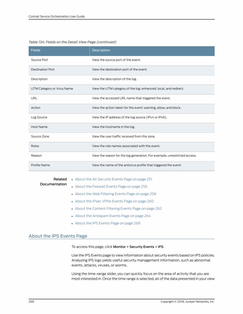
Table 134: Fields on the Detail View Page (continued)
DescriptionFields
View the source port of the event.Source Port
View the destination port of the event.Destination Port
View the description of the log.Description
View the UTM category of the log: enhanced, local, and redirect.UTM Category or Virus Name
View the accessed URL name that triggered the event.URL
View the action taken for the event: warning, allow, and block.Action
View the IP address of the log source (IPv4 or IPv6).Log Source
View the hostname in the log.Host Name
View the user traffic received from the zone.Source Zone
View the role names associated with the event.Roles
View the reason for the log generation. For example, unrestricted access.Reason
View the name of the antivirus profile that triggered the event.Profile Name
RelatedDocumentation
About the All Security Events Page on page 251•
• About the Firewall Events Page on page 255
• About theWeb Filtering Events Page on page 258
• About the IPsec VPNs Events Page on page 260
• About the Content Filtering Events Page on page 262
• About the Antispam Events Page on page 264
• About the IPS Events Page on page 268
About the IPS Events Page
To access this page, clickMonitor > Security Events > IPS.
Use the IPS Events page to view information about security events based on IPS policies.
Analyzing IPS logs yields useful security management information, such as abnormal
events, attacks, viruses, or worms.
Using the time-range slider, you can quickly focus on the area of activity that you are
most interested in. Once the time range is selected, all of the data presented in your view
Copyright © 2018, Juniper Networks, Inc.268
Contrail Service Orchestration User Guide
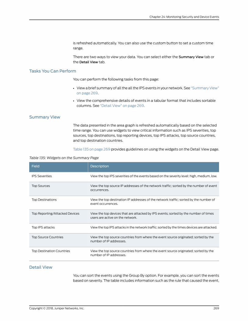
is refreshed automatically. You can also use the custom button to set a custom time
range.
There are two ways to view your data. You can select either the Summary View tab or
the Detail View tab.
Tasks You Can Perform
You can perform the following tasks from this page:
• Viewabrief summaryof all theall the IPSevents in your network. See “SummaryView”
on page 269.
• View the comprehensive details of events in a tabular format that includes sortable
columns. See “Detail View” on page 269.
Summary View
The data presented in the area graph is refreshed automatically based on the selected
time range. You can use widgets to view critical information such as IPS severities, top
sources, top destinations, top reporting devices, top IPS attacks, top source countries,
and top destination countries.
Table 135 on page 269 provides guidelines on using thewidgets on the Detail View page.
Table 135: Widgets on the Summary Page
DescriptionField
View the top IPS severities of the events based on the severity level: high, medium, low.IPS Severities
View the top source IP addresses of the network traffic; sorted by the number of eventoccurrences.
Top Sources
View the top destination IP addresses of the network traffic; sorted by the number ofevent occurrences.
Top Destinations
View the top devices that are attacked by IPS events; sorted by the number of timesusers are active on the network.
Top Reporting/Attacked Devices
View the top IPSattacks in the network traffic; sortedby the timesdevices are attacked.Top IPS attacks
View the top source countries fromwhere the event source originated; sorted by thenumber of IP addresses.
Top Source Countries
View the top source countries fromwhere the event source originated; sorted by thenumber of IP addresses.
Top Destination Countries
Detail View
You can sort the events using the Group By option. For example, you can sort the events
based on severity. The table includes information such as the rule that caused the event,
269Copyright © 2018, Juniper Networks, Inc.
Chapter 24: Monitoring Security and Device Events
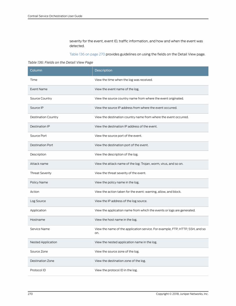
severity for the event, event ID, traffic information, and how and when the event was
detected.
Table 136 on page 270 provides guidelines on using the fields on the Detail View page.
Table 136: Fields on the Detail View Page
DescriptionColumn
View the time when the log was received.Time
View the event name of the log.Event Name
View the source country name fromwhere the event originated.Source Country
View the source IP address fromwhere the event occurred.Source IP
View the destination country name fromwhere the event occurred.Destination Country
View the destination IP address of the event.Destination IP
View the source port of the event.Source Port
View the destination port of the event.Destination Port
View the description of the log.Description
View the attack name of the log: Trojan, worm, virus, and so on.Attack name
View the threat severity of the event.Threat Severity
View the policy name in the log.Policy Name
View the action taken for the event: warning, allow, and block.Action
View the IP address of the log source.Log Source
View the application name fromwhich the events or logs are generated.Application
View the host name in the log.Hostname
View the name of the application service. For example, FTP, HTTP, SSH, and soon.
Service Name
View the nested application name in the log.Nested Application
View the source zone of the log.Source Zone
View the destination zone of the log.Destination Zone
View the protocol ID in the log.Protocol ID
Copyright © 2018, Juniper Networks, Inc.270
Contrail Service Orchestration User Guide
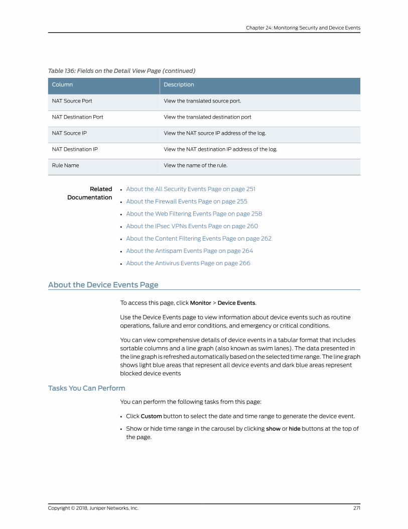
Table 136: Fields on the Detail View Page (continued)
DescriptionColumn
View the translated source port.NAT Source Port
View the translated destination portNAT Destination Port
View the NAT source IP address of the log.NAT Source IP
View the NAT destination IP address of the log.NAT Destination IP
View the name of the rule.Rule Name
RelatedDocumentation
About the All Security Events Page on page 251•
• About the Firewall Events Page on page 255
• About theWeb Filtering Events Page on page 258
• About the IPsec VPNs Events Page on page 260
• About the Content Filtering Events Page on page 262
• About the Antispam Events Page on page 264
• About the Antivirus Events Page on page 266
About the Device Events Page
To access this page, clickMonitor > Device Events.
Use the Device Events page to view information about device events such as routine
operations, failure and error conditions, and emergency or critical conditions.
You can view comprehensive details of device events in a tabular format that includes
sortable columns and a line graph (also known as swim lanes). The data presented in
the line graph is refreshedautomatically basedon the selected time range. The line graph
shows light blue areas that represent all device events and dark blue areas represent
blocked device events
Tasks You Can Perform
You can perform the following tasks from this page:
• Click Custom button to select the date and time range to generate the device event.
• Show or hide time range in the carousel by clicking show or hide buttons at the top of
the page.
271Copyright © 2018, Juniper Networks, Inc.
Chapter 24: Monitoring Security and Device Events
Advanced Search
You can perform advanced search of all events using the text field present above the
tabular column. It includes the logical operators as part of the filter string. Enter the
search string in the text field andbasedon your input, a list of items from the filter context
menu is displayed. . You can select a value from the list and then select a valid logical
operator to perform the advanced search operation Press Enter to display the search
result in the tabular column below.
To delete the search string in the text field, click the delete icon (X icon)..
Examples of event log filters are shown in the following list:
• Specific events originating from or landing within United States
Source Country = United States OR Destination Country = United States AND Event
Name = IDP_ATTACK_LOG_EVENT, IDP_ATTACK_LOG_EVENT_LS,
IDP_APPDDOS_APP_ATTACK_EVENT_LS, IDP_APPDDOS_APP_STATE_EVENT,
IDP_APPDDOS_APP_STATE_EVENT_LS, AV_VIRUS_DETECTED_MT,
AV_VIRUS_DETECTED, ANTISPAM_SPAM_DETECTED_MT,
ANTISPAM_SPAM_DETECTED_MT_LS, FWAUTH_FTP_USER_AUTH_FAIL,
FWAUTH_FTP_USER_AUTH_FAIL_LS, FWAUTH_HTTP_USER_AUTH_FAIL,
FWAUTH_HTTP_USER_AUTH_FAIL_LS, FWAUTH_TELNET_USER_AUTH_FAIL,
FWAUTH_TELNET_USER_AUTH_FAIL_LS,
FWAUTH_WEBAUTH_FAIL,FWAUTH_WEBAUTH_FAIL_LS
• User wants to filter all RT flow sessions originating from IPs in specific countries and
landing on IPs in specific countries
EventName=RT_FLOW_SESSION_CREATE,RT_FLOW_SESSION_CLOSEANDSource
IP = 177.1.1.1,220.194.0.150,14.1.1.2,196.194.56.4 AND Destination IP =
255.255.255.255,10.207.99.75,10.207.99.72,223.165.27.13 AND Source Country =
Brazil,United States,China,Russia,Algeria AND Destination Country =
Germany,India,United States
• Traffic between zone pairs for policy – IDP2
Source Zone= trust ANDDestination Zone= untrust, internal ANDPolicy Name= IDP2
• UTM logs coming from specific source country, destination country, source IPs with or
without specific destination IPs
Event Category = antispam, antivirus, contentfilter, webfilter AND Source Country =
Australia AND Destination Country = Turkey, United States, Australia AND Source IP
= 1.0.0.0,1.1.1.3 OR Destination IP = 74.125.224.47,5.56.17.61
• Events with specific sources IPs or events hitting HTP, FTP, HTTP, and unknown
applications coming from host DC-SRX1400-1 or VSRX-75.
Application = tftp, ftp, http, unknown OR Source IP = 192.168.34.10,192.168.1.26 AND
Hostname = dc-srx1400-1,vsrx-75
Copyright © 2018, Juniper Networks, Inc.272
Contrail Service Orchestration User Guide
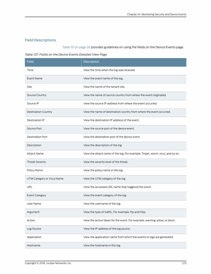
Field Descriptions
Table 10 on page 26 provides guidelines on using the fields on the Device Events page.
Table 137: Fields on the Device Events Detailed View Page
DescriptionField
View the time when the log was received.Time
View the event name of the log.Event Name
View the name of the tenant site.Site
View the name of source country fromwhere the event originated.Source Country
View the source IP address fromwhere the event occurred.Source IP
View the name of destination country fromwhere the event occurred.Destination Country
View the destination IP address of the event.Destination IP
View the source port of the device event.Source Port
View the destination port of the device event.Destination Port
View the description of the log.Description
View the attack name of the log. For example, Trojan, worm, virus, and so on.Attack Name
View the severity level of the threat.Threat Severity
View the policy name in the log.Policy Name
View the UTM category of the log.UTM Category or Virus Name
View the accessed URL name that triggered the event.URL
View the event category of the log.Event Category
View the username of the log.User Name
View the type of traffic. For example, ftp and http.Argument
View the action taken for the event. For example, warning, allow, or block.Action
View the IP address of the log source.Log Source
View the application name fromwhich the events or logs are generated.Application
View the hostname in the log.Hostname
273Copyright © 2018, Juniper Networks, Inc.
Chapter 24: Monitoring Security and Device Events
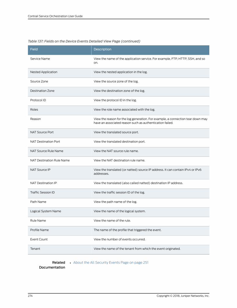
Table 137: Fields on the Device Events Detailed View Page (continued)
DescriptionField
View the name of the application service. For example, FTP, HTTP, SSH, and soon.
Service Name
View the nested application in the log.Nested Application
View the source zone of the log.Source Zone
View the destination zone of the log.Destination Zone
View the protocol ID in the log.Protocol ID
View the role name associated with the log.Roles
View the reason for the log generation. For example, a connection tear downmayhave an associated reason such as authentication failed.
Reason
View the translated source port.NAT Source Port
View the translated destination port.NAT Destination Port
View the NAT source rule name.NAT Source Rule Name
View the NAT destination rule name.NAT Destination Rule Name
View the translated (or natted) source IP address. It can contain IPv4 or IPv6addresses.
NAT Source IP
View the translated (also called natted) destination IP address.NAT Destination IP
View the traffic session ID of the log.Traffic Session ID
View the path name of the log.Path Name
View the name of the logical system.Logical System Name
View the name of the rule.Rule Name
The name of the profile that triggered the event.Profile Name
View the number of events occurred.Event Count
View the name of the tenant fromwhich the event originated.Tenant
RelatedDocumentation
About the All Security Events Page on page 251•
Copyright © 2018, Juniper Networks, Inc.274
Contrail Service Orchestration User Guide
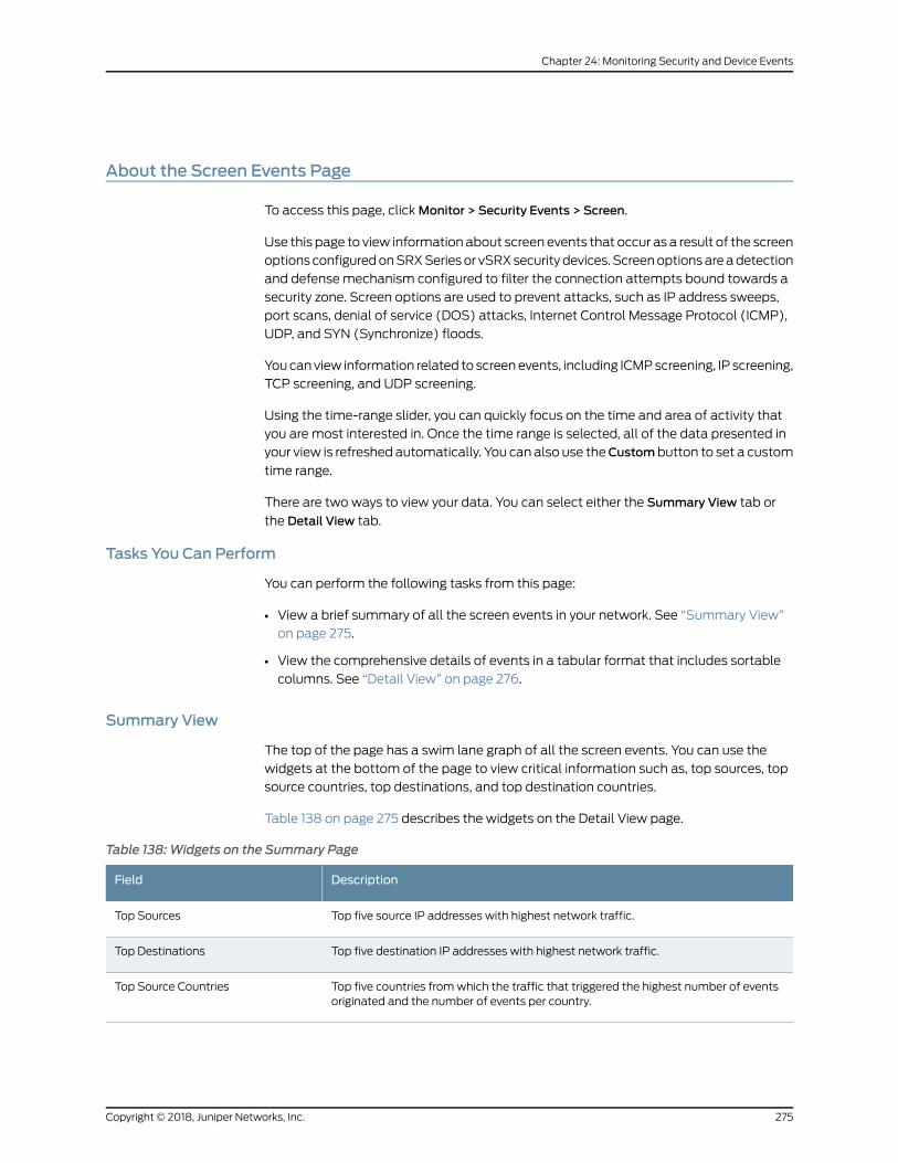
About the Screen Events Page
To access this page, clickMonitor > Security Events > Screen.
Use this page to view information about screen events that occur as a result of the screen
optionsconfiguredonSRXSeriesor vSRXsecuritydevices. Screenoptionsareadetection
and defense mechanism configured to filter the connection attempts bound towards a
security zone. Screen options are used to prevent attacks, such as IP address sweeps,
port scans, denial of service (DOS) attacks, Internet Control Message Protocol (ICMP),
UDP, and SYN (Synchronize) floods.
Youcanview information related to screenevents, including ICMPscreening, IP screening,
TCP screening, and UDP screening.
Using the time-range slider, you can quickly focus on the time and area of activity that
you are most interested in. Once the time range is selected, all of the data presented in
your view is refreshed automatically. You can also use theCustombutton to set a custom
time range.
There are two ways to view your data. You can select either the Summary View tab or
the Detail View tab.
Tasks You Can Perform
You can perform the following tasks from this page:
• View a brief summary of all the screen events in your network. See “Summary View”
on page 275.
• View the comprehensive details of events in a tabular format that includes sortable
columns. See “Detail View” on page 276.
Summary View
The top of the page has a swim lane graph of all the screen events. You can use the
widgets at the bottom of the page to view critical information such as, top sources, top
source countries, top destinations, and top destination countries.
Table 138 on page 275 describes the widgets on the Detail View page.
Table 138:Widgets on the Summary Page
DescriptionField
Top five source IP addresses with highest network traffic.Top Sources
Top five destination IP addresses with highest network traffic.Top Destinations
Top five countries fromwhich the traffic that triggered the highest number of eventsoriginated and the number of events per country.
Top Source Countries
275Copyright © 2018, Juniper Networks, Inc.
Chapter 24: Monitoring Security and Device Events
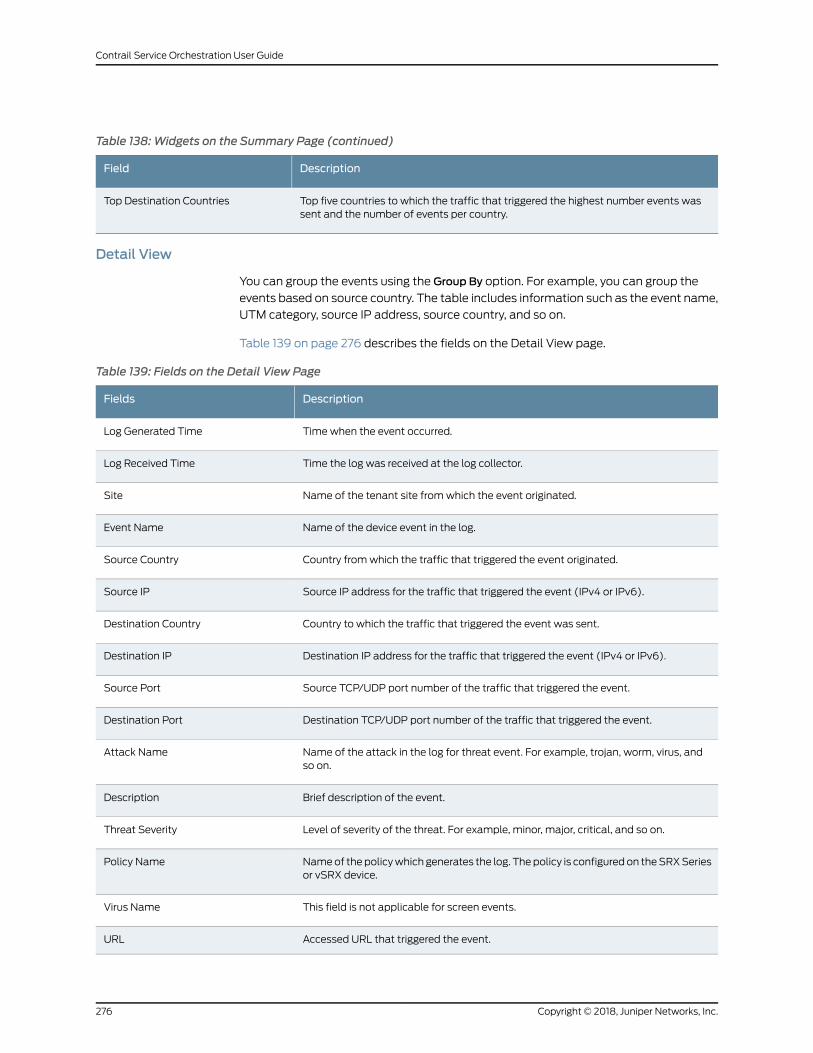
Table 138:Widgets on the Summary Page (continued)
DescriptionField
Top five countries to which the traffic that triggered the highest number events wassent and the number of events per country.
Top Destination Countries
Detail View
You can group the events using the Group By option. For example, you can group the
events based on source country. The table includes information such as the event name,
UTM category, source IP address, source country, and so on.
Table 139 on page 276 describes the fields on the Detail View page.
Table 139: Fields on the Detail View Page
DescriptionFields
Time when the event occurred.Log Generated Time
Time the log was received at the log collector.Log Received Time
Name of the tenant site fromwhich the event originated.Site
Name of the device event in the log.Event Name
Country fromwhich the traffic that triggered the event originated.Source Country
Source IP address for the traffic that triggered the event (IPv4 or IPv6).Source IP
Country to which the traffic that triggered the event was sent.Destination Country
Destination IP address for the traffic that triggered the event (IPv4 or IPv6).Destination IP
Source TCP/UDP port number of the traffic that triggered the event.Source Port
Destination TCP/UDP port number of the traffic that triggered the event.Destination Port
Name of the attack in the log for threat event. For example, trojan, worm, virus, andso on.
Attack Name
Brief description of the event.Description
Level of severity of the threat. For example, minor, major, critical, and so on.Threat Severity
Nameof thepolicywhich generates the log. Thepolicy is configuredon theSRXSeriesor vSRX device.
Policy Name
This field is not applicable for screen events.Virus Name
Accessed URL that triggered the event.URL
Copyright © 2018, Juniper Networks, Inc.276
Contrail Service Orchestration User Guide
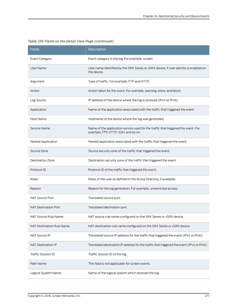
Table 139: Fields on the Detail View Page (continued)
DescriptionFields
Event category in the log. For example, screen.Event Category
User name identified by the SRX Series or vSRX device, if user identity is enabled onthe device.
User Name
Type of traffic. For example, FTP and HTTP.Argument
Action taken for the event. For example, warning, allow, and block.Action
IP address of the device where the log is received (IPv4 or IPv6).Log Source
Name of the application associated with the traffic that triggered the event.Application
Hostname of the device where the log was generated.Host Name
Name of the application service used for the traffic that triggered the event. Forexample, FTP, HTTP, SSH, and so on.
Service Name
Nested application associated with the traffic that triggered the event.Nested Application
Source security zone of the traffic that triggered the event.Source Zone
Destination security zone of the traffic that triggered the event.Destination Zone
Protocol ID of the traffic that triggered the event.Protocol ID
Roles of the user as defined in the Active Directory, if available.Roles
Reason for the log generation. For example, unrestricted access.Reason
Translated source port.NAT Source Port
Translated destination port.NAT Destination Port
NAT source rule name configured on the SRX Series or vSRX device.NAT Source Rule Name
NAT destination rule name configured on the SRX Series or vSRX device.NAT Destination Rule Name
Translated source IP address for the traffic that triggered the event (IPv4 or IPv6).NAT Source IP
Translateddestination IP address for the traffic that triggered the event (IPv4or IPv6).NAT Destination IP
Traffic session ID of the log.Traffic Session ID
This field is not applicable for screen events.Path Name
Name of the logical systemwhich received the log.Logical System Name
277Copyright © 2018, Juniper Networks, Inc.
Chapter 24: Monitoring Security and Device Events
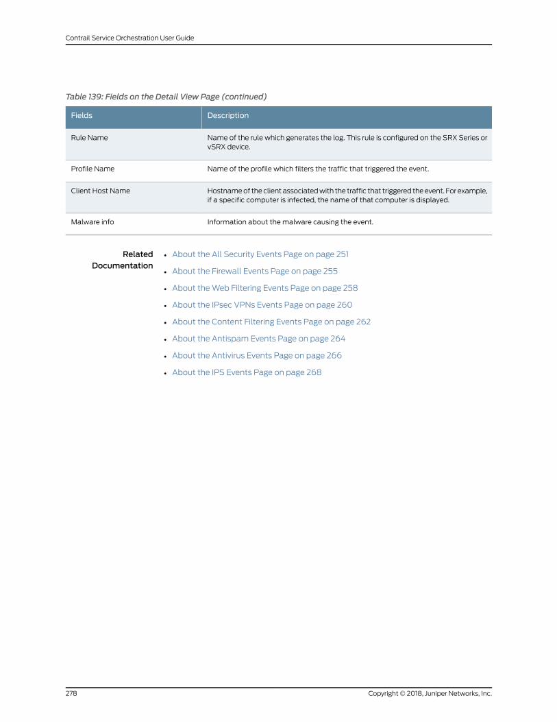
Table 139: Fields on the Detail View Page (continued)
DescriptionFields
Name of the rule which generates the log. This rule is configured on the SRX Series orvSRX device.
Rule Name
Name of the profile which filters the traffic that triggered the event.Profile Name
Hostnameof theclientassociatedwith the traffic that triggered theevent. For example,if a specific computer is infected, the name of that computer is displayed.
Client Host Name
Information about the malware causing the event.Malware info
RelatedDocumentation
• About the All Security Events Page on page 251
• About the Firewall Events Page on page 255
• About theWeb Filtering Events Page on page 258
• About the IPsec VPNs Events Page on page 260
• About the Content Filtering Events Page on page 262
• About the Antispam Events Page on page 264
• About the Antivirus Events Page on page 266
• About the IPS Events Page on page 268
Copyright © 2018, Juniper Networks, Inc.278
Contrail Service Orchestration User Guide
CHAPTER 25
Monitoring SD-WAN Events
• SD-WAN Events Overview on page 279
• About the SD-WAN Events Page on page 280
SD-WAN Events Overview
Service-level agreements (SLAs) define the expected class of service (CoS) for all
applicationsandapplicationgroups inasite.Thenetworkoperatorneeds tools tomeasure
andmonitor the performancemetrics for all applications to determine the quality of the
network andadherence toanassuredCoS. Toensure compliancewithSLAs, thenetwork
operatoralsoneeds tools to take remedial actionwhennetworkperformancedeteriorates
and SLAs are not being met. SD-WAN link-switch events enable the network to switch
WAN links to meet the site’s SLA requirements when the network-designatedWAN link
is unable to meet the site’s SLA requirements.
Because SLA parameters override the path preference, in dynamic SD-WANpolicies, the
SD-WANnetwork chooses the best possibleWAN link for trafficmanagement. TheWAN
link is chosen is based on the SLA parameters defined in the SLA profile. If multiple links
match the SLA profile, the least loaded link is chosen. When a policy intent is deployed
on a site, if theWAN link chosen by the SD-WAN network is unable to meet the SLA
requirements in runtime, then the site switchesWAN links tomeet theSLA requirements.
This link switching is called an SD-WAN event. Link switching also takes into account
the priority defined in the SLA profile and SLA profiles with higher priority are given
precedence while finding alternateWAN links. The ability of a site to switchWAN links
ensures that SLA requirements are met and instances of not meeting the SLA
requirements are minimized.
In static policies, link switching cannot occur even if the designatedWAN link is unable
to meet the SLA requirements, because path preference is defined.
RelatedDocumentation
About the SD-WAN Events Page on page 280•
• SLA Profiles and SD-WAN Policies Overview on page 437
279Copyright © 2018, Juniper Networks, Inc.
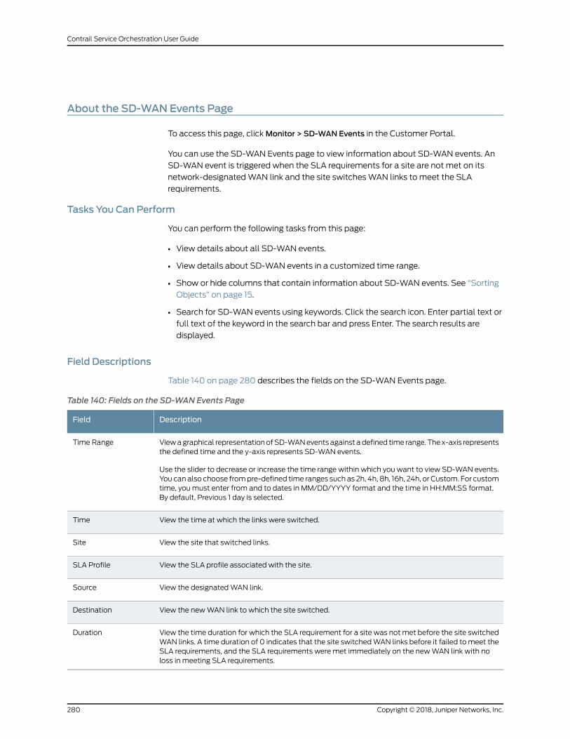
About the SD-WAN Events Page
To access this page, clickMonitor > SD-WAN Events in the Customer Portal.
You can use the SD-WAN Events page to view information about SD-WAN events. An
SD-WAN event is triggered when the SLA requirements for a site are not met on its
network-designatedWAN link and the site switchesWAN links to meet the SLA
requirements.
Tasks You Can Perform
You can perform the following tasks from this page:
• View details about all SD-WAN events.
• View details about SD-WAN events in a customized time range.
• Show or hide columns that contain information about SD-WAN events. See “Sorting
Objects” on page 15.
• Search for SD-WAN events using keywords. Click the search icon. Enter partial text or
full text of the keyword in the search bar and press Enter. The search results are
displayed.
Field Descriptions
Table 140 on page 280 describes the fields on the SD-WAN Events page.
Table 140: Fields on the SD-WAN Events Page
DescriptionField
Viewagraphical representationofSD-WANeventsagainst adefined time range. Thex-axis representsthe defined time and the y-axis represents SD-WAN events.
Use the slider to decrease or increase the time range within which you want to view SD-WAN events.You can also choose frompre-defined time ranges such as 2h, 4h, 8h, 16h, 24h, or Custom. For customtime, youmust enter from and to dates in MM/DD/YYYY format and the time in HH:MM:SS format.By default, Previous 1 day is selected.
Time Range
View the time at which the links were switched.Time
View the site that switched links.Site
View the SLA profile associated with the site.SLA Profile
View the designatedWAN link.Source
View the newWAN link to which the site switched.Destination
View the time duration for which the SLA requirement for a site was not met before the site switchedWAN links. A time duration of 0 indicates that the site switchedWAN links before it failed tomeet theSLA requirements, and the SLA requirements were met immediately on the newWAN link with noloss in meeting SLA requirements.
Duration
Copyright © 2018, Juniper Networks, Inc.280
Contrail Service Orchestration User Guide

RelatedDocumentation
• SD-WAN Events Overview on page 279
281Copyright © 2018, Juniper Networks, Inc.
Chapter 25: Monitoring SD-WAN Events

Copyright © 2018, Juniper Networks, Inc.282
Contrail Service Orchestration User Guide
CHAPTER 26
Monitoring Applications
• About the SLA Performance of a Single Tenant Page on page 283
• Viewing the SLA Performance of a Site on page 285
• Viewing the SLA Performance of an Application or Application Group on page 290
• Application Visibility Overview on page 291
• About the Application Visibility Page on page 291
• Selecting Devices on page 294
About the SLA Performance of a Single Tenant Page
To access this page, selectMonitor > Application SLA Performance > Tenant-Name SLA
Performance in the Customer Portal.
You can use the Tenant-Name SLA Performance page to view performance reports for
all sites in a tenant. You can view the SLA performance of all sites that havemet and all
the sites that have not met the defined SLA target values for the specified time range.
You can customize your view and also the time range for which youwant to view the SLA
performance.
Tasks You Can Perform
You can perform the following tasks from this page:
• View the SLA performance for all sites in the tenant that havemet the defined SLA
target values, without switchingWAN links, for the specified time range.
• View the SLA performance for all sites in the tenant that havemet the defined SLA
target values, after switchingWAN links, for the specified time range.
• View the SLA performance for all sites in a tenant that have not met the defined SLA
target values for the specified time range.
• View the SLA performance for all sites in a tenant in grid or card views.
Select card view or grid view at the top right of the page. By default, card view is
selected.
• Customize the time range to view the SLA performance for all sites in a tenant.
• View the SLA performance for multiple departments within a single tenant.
283Copyright © 2018, Juniper Networks, Inc.
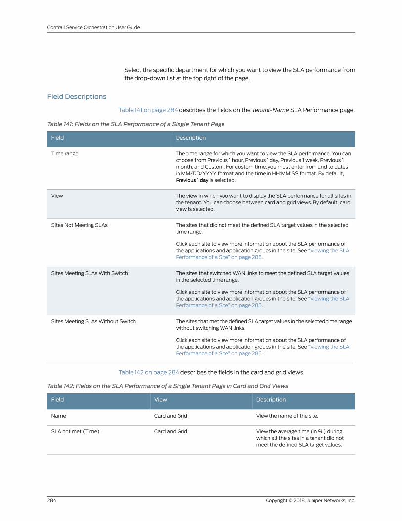
Select the specific department for which you want to view the SLA performance from
the drop-down list at the top right of the page.
Field Descriptions
Table 141 on page 284 describes the fields on the Tenant-Name SLA Performance page.
Table 141: Fields on the SLA Performance of a Single Tenant Page
DescriptionField
The time range for which you want to view the SLA performance. You canchoose from Previous 1 hour, Previous 1 day, Previous 1 week, Previous 1month, and Custom. For custom time, youmust enter from and to datesin MM/DD/YYYY format and the time in HH:MM:SS format. By default,Previous 1 day is selected.
Time range
The view in which you want to display the SLA performance for all sites inthe tenant. You can choose between card and grid views. By default, cardview is selected.
View
The sites that did not meet the defined SLA target values in the selectedtime range.
Click each site to viewmore information about the SLA performance ofthe applications and application groups in the site. See “Viewing the SLAPerformance of a Site” on page 285.
Sites Not Meeting SLAs
The sites that switchedWAN links to meet the defined SLA target valuesin the selected time range.
Click each site to viewmore information about the SLA performance ofthe applications and application groups in the site. See “Viewing the SLAPerformance of a Site” on page 285.
Sites Meeting SLAsWith Switch
The sites thatmet the defined SLA target values in the selected time rangewithout switchingWAN links.
Click each site to viewmore information about the SLA performance ofthe applications and application groups in the site. See “Viewing the SLAPerformance of a Site” on page 285.
Sites Meeting SLAsWithout Switch
Table 142 on page 284 describes the fields in the card and grid views.
Table 142: Fields on the SLA Performance of a Single Tenant Page in Card and Grid Views
DescriptionViewField
View the name of the site.Card and GridName
View the average time (in%) duringwhich all the sites in a tenant did notmeet the defined SLA target values.
Card and GridSLA not met (Time)
Copyright © 2018, Juniper Networks, Inc.284
Contrail Service Orchestration User Guide
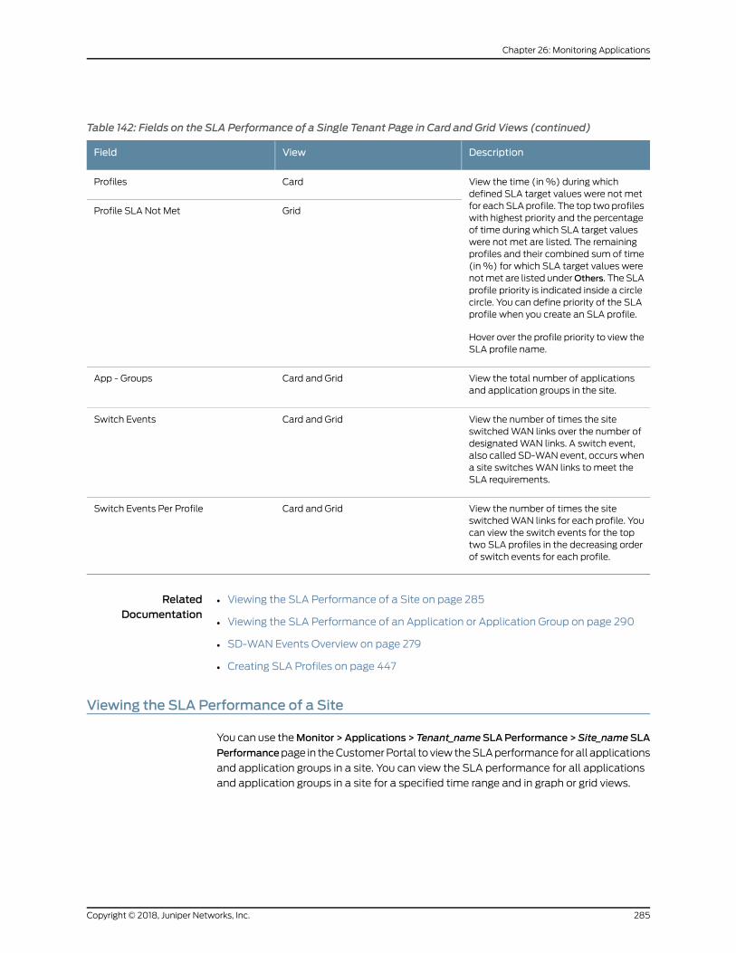
Table 142: Fields on the SLA Performance of a Single Tenant Page in Card and Grid Views (continued)
DescriptionViewField
View the time (in%) during whichdefined SLA target values were not metfor eachSLAprofile. The top twoprofileswith highest priority and the percentageof time during which SLA target valueswere not met are listed. The remainingprofiles and their combined sum of time(in%) for which SLA target values werenotmet are listed underOthers. The SLAprofile priority is indicated inside a circlecircle. You can define priority of the SLAprofile when you create an SLA profile.
Hover over the profile priority to view theSLA profile name.
CardProfiles
GridProfile SLA Not Met
View the total number of applicationsand application groups in the site.
Card and GridApp - Groups
View the number of times the siteswitchedWAN links over the number ofdesignatedWAN links. A switch event,also called SD-WAN event, occurs whena site switchesWAN links to meet theSLA requirements.
Card and GridSwitch Events
View the number of times the siteswitchedWAN links for each profile. Youcan view the switch events for the toptwo SLA profiles in the decreasing orderof switch events for each profile.
Card and GridSwitch Events Per Profile
RelatedDocumentation
Viewing the SLA Performance of a Site on page 285•
• Viewing the SLA Performance of an Application or Application Group on page 290
• SD-WAN Events Overview on page 279
• Creating SLA Profiles on page 447
Viewing the SLA Performance of a Site
You can use theMonitor >Applications>Tenant_nameSLAPerformance>Site_nameSLA
Performancepage in theCustomerPortal to viewtheSLAperformance for all applications
and application groups in a site. You can view the SLA performance for all applications
and application groups in a site for a specified time range and in graph or grid views.
285Copyright © 2018, Juniper Networks, Inc.
Chapter 26: Monitoring Applications
The Site_name SLA Performance page is divided into the following sections:
• SLA Not Met by SLA Profiles on page 286
• Applications SLA Performance by Throughput on page 287
• SLA Performance for ALL on page 289
SLANotMet by SLA Profiles
You can use the SLANotMet by SLA Profiles section on the Site_name SLA Performance
page to view the SLA profiles for which SLA requirements were not met and the time at
which theywerenotmet. They-axis represents theSLAprofilesand thex-axis represents
the specified time range. The SLANotMet by SLA Profiles section can be viewed and
remains the same in both graph and grid views.
To view a graphical representation of SLA profiles for which SLA target values were not
met:
1. Select the time range forwhich youwant to view theSLAprofiles forwhichSLA target
values were not met. You can choose from Previous 1 hour, Previous 1 day, Previous 1
week, Previous 1 month, and Custom. For custom time, youmust enter from and to
dates inMM/DD/YYYY format and the time inHH:MM:SS format. By default, Previous
1 day is selected.
The graphical representation of SLA profiles for which SLA target values were not
met is displayed for the selected time range.
2. (Optional) You can use the sliders at the sides of the graph to further customize the
time range.
The graphical representation of SLA profiles for which SLA target values were not
met is refreshed and displayed for the customized time range. The graphical
representation of SLA performance data in the subsequent sections on the page is
also refreshed and displayed for the customized time range.
Copyright © 2018, Juniper Networks, Inc.286
Contrail Service Orchestration User Guide
Applications SLA Performance by Throughput
You can use the Applications SLA Performance by Throughput section on the Site_name
SLA Performance page to view average throughput performance of all applications and
application groups in a site. You can also customize your view by selecting graph or grid
views. In the graph view, you can further select scatter plot or tree map.
Toviewagraphical representationofaverage throughputperformanceofall applications
and application groups in a site:
1. Select Graph View at the top right of the page. By default, Graph View is selected.
Agraphical representationof average throughput performanceof all applications and
application groups in a site against the target throughput is displayed in the Scatter
Plot view. The y-axis represents the average throughput. 0%on the x-axis represents
the target throughput (in%) defined in the SLA profiles, while the regions on the left
and right of the target represent percentages below and above the target throughput,
respectively.
A carousel at the bottom of the section also displays the list of all applications and
application groupswith their SLA profiles, target throughput, and average throughput
values.
2. Click Legend at the bottom right of the section to view the plotting legend.
The items described in the Legend are:
• A single application is represented by a blue circle.
• An application group is represented by a blue square.
• Anapplicationor applicationgroupwhose target throughput value in theSLAprofile
wasmodified during runtime is represented by an uncolored circle and uncolored
square, respectively.
• The SLA profiles are represented by their priority numbers within the colored or
uncolored circles and squares.
3. (Optional) You can use the sliders at the sides of the graph further to customize the
time range.
The carousel is refreshed for the customized time range.
4. Click the circles or squares to viewmore information about the application or
applicationgroups.See “Viewing theSLAPerformanceofanApplicationorApplication
Group” on page 290.
5. Select TreeMap at the top right of the section to view a list of all applications and
application groups in a site and their average throughput values.
A list of all applications and application groups in a site along with their associated
SLA profiles and the average throughput values is displayed.
287Copyright © 2018, Juniper Networks, Inc.
Chapter 26: Monitoring Applications
To view a tabular representation of average throughput performance of all applications
and application groups in a site:
1. Select Grid View at the top right of the page.
A list of all applications and application groups along with their SLA profiles, average
throughput, and target throughput values is displayed in a tabular format.
Table 143 on page 288 describes the fields on the Applications SLA Performance by
Throughput grid view.
Table 143: Fields on the Applications SLA Performance by Throughput Grid View
DescriptionField
View name of the application or application group.Name
View the SLA profile associated with the application or application group.SLA Profile
View the type—application or application groupType
View the category of the application or application group. The value of Category can beMessaging, Web, Infrastructure, Remote-Access, Multimedia, Video, and so on.
Category
View number of sessions consumed by the application or application group.Sessions
View the average throughput performance value (in%) of the application or applicationgroup. The upward triangle on the left of the average throughput performance valueindicates that the average throughput is higher than the target throughput configured inthe SLA profile of the application or application group. The value (in%) denotes thepercentage above the target throughput value. Similarly, the downward triangle on theleft of the average throughput performance value indicates that the average throughputis lower than the target throughput configured in the SLA profile of the application orapplication group. The value (in%) denotes the percentage below the target throughputvalue.
Throughput Avg. Performance
2. (Optional) Click the details icon to the left of the application or application group
name to viewmore information about the application or application group. See
“Viewing the SLA Performance of an Application or Application Group” on page 290.
Copyright © 2018, Juniper Networks, Inc.288
Contrail Service Orchestration User Guide
SLA Performance for ALL
View a graphical representation of the performance of the SLA parameters such as
round-trip time (RTT), latency, packet loss, and jitter for the specified time range for
MPLS and InternetWAN links for all SLA profiles. The y-axis represents the SLA
parameters and the x-axis represents the specified time range. You can also view the
respective target SLA parameters in the graphs.
NOTE: Thegraphical representationof theperformanceofallSLAparametersfor theWAN links is available only in the graph view.
To view a graphical representation of the performance of all SLA parameters for the
WAN links:
• Select All at the top right of the section. By default, All is selected.
A graphical representation of the performance of the SLA parameters such as RTT,
latency, packet loss, and jitter for the specified time range for allWAN links is displayed.
• Selectwan_0,wan_1, and so on at the top right of the section to view the performance
of the SLA parameters for the MPLS and InternetWAN links. You can enable and
configurewan_0,wan_1, and so on andmap them toMPLS or Internet links when you
create a site.
The graphical representation of the performance of the SLA parameters such as RTT,
latency, packet loss, and jitter for the specified time range is refreshed and only the
performance for the selectedWAN link is displayed.
• (Optional) Click Legend at the bottom right of the section to view the plotting legend
for thehorizontal dotted linesparallel to the x-axis in thegraphs. Thehorizontal dotted
lines represent the respective target SLA parameters of the SLA profiles.
NOTE: RTT is represented as Delay on the “Application SLA Profiles” onpage 446 page.
RelatedDocumentation
About the SLA Performance of a Single Tenant Page on page 283•
• Viewing the SLA Performance of an Application or Application Group on page 290
289Copyright © 2018, Juniper Networks, Inc.
Chapter 26: Monitoring Applications
Viewing the SLA Performance of an Application or Application Group
You can use theMonitor > Applications > Tenant-Name SLA Performance > Site-Name
SLAPerformancepage in theCustomerPortal to view theSLAperformance for individual
applications and application groups in a site. You can also view the SLA performance of
the associated SLA profile for all SLA parameters.
To view SLA performance of an application or application groups:
• Click one of the circles or squares in the Applications SLAPerformance by Throughput
section on the Site-Name SLA Performance page.
The page that appears displays SLA performance details of the application or
application group.
Table 144 on page 290 describes the fields on the application or application group SLA
Performance details page.
Table 144: Fields on the Application or Application Group Details Page
DescriptionField
View the category of the application or application group. The category can be Messaging,Web, Infrastructure, Remote-Access, Multimedia, Video, and so on.
You can also view a description of the application or application group.
Category and Description
View the name of the SLA profile associated with the application or application group.SLA
View the current target throughput defined in the SLA profile associated with the applicationor application group. If the target throughput wasmodified during runtime, the date and timewhen the throughput wasmodified and the previously defined throughput value are alsodisplayed.
Target
View the average throughout performance (in%) above or below the configured targetthroughput. The average throughput (in Mbps) is displayed within parentheses.
Avg. Performance
View a graphical representation of the SLAmetrics by throughput during the specified timerange for thatapplicationorapplicationgroup.They-axis represents the throughput (inMbps).The x-axis represents the specified time range. Hover over the graph to view the throughputvalue and time at any specified point. You can also view the sessions consumed by theWANlinks for the application or application group time range.
SLA Metrics by Throughput
Copyright © 2018, Juniper Networks, Inc.290
Contrail Service Orchestration User Guide
Table 144: Fields on the Application or Application Group Details Page (continued)
DescriptionField
View the performance for all the SLA parameters of the SLA profile associated with theapplication or application group. The SLA performance is represented by a color-coded donutchart. The section in blue in the donut chart indicates the percentage of time duringwhich SLArequirements for the SLA profile were met. The section in red in the donut chart indicates thepercentage of time during which SLA requirements for the SLA profile were not met.
Click the red colored section of the donut chart to viewmore information about when SLArequirements for the SLA profile were not met. The SLA Profile Performance page appears.The SLA Profile Performance page displays the following fields:
• SLA Profile—SLA profile associated with the application or application group
• Target—Target throughput configured in the SLA profile
• SLAs Not Met—Percentage of time SLA requirements were not met for the SLA profile
• Sessions—Number of sessions consumed by the application or application group
• Start Time—Time at which theWAN links associated with the application or applicationgroups started to fail meeting the SLA requirements
• End Time—Time at which SLA profile requirements started to bemet again
• Avg Val—Average throughput (in Mbps) when the SLA requirements started to fail
• Duration—Total duration (in seconds) during which SLA requirements were not met
• From—SourceWAN link
• To—DestinationWAN link
Global SLA ProfilePerformance
RelatedDocumentation
About the SLA Performance of a Single Tenant Page on page 283•
• Viewing the SLA Performance of a Site on page 285
Application Visibility Overview
You can use the Application Visibility page to view information about bandwidth
consumption, session establishment, and the risks associated with your applications.
Analyzing your network applications yields useful security management information,
such as abnormal applications that can lead to data loss, heavy bandwidth usage,
time-consuming applications, and personal applications that can elevate business risks.
RelatedDocumentation
About the Application Visibility Page on page 291•
• Selecting Devices on page 294
About the Application Visibility Page
To access this page, selectMonitor > Applications > Visibility.
There are two ways in which you can view your application visibility data—Chart View or
Grid View. By default, the data is displayed in Chart View.
291Copyright © 2018, Juniper Networks, Inc.
Chapter 26: Monitoring Applications
Tasks You Can Perform
You can perform the following tasks from this page:
• View application visibility data in Chart View. See “Chart View” on page 292.
• View application visibility data in Grid View. See “Grid View” on page 293.
• Selectadevice towhich theapplicationvisibility settingsareapplicable.See “Selecting
Devices” on page 294.
Chart View
Click the Chart View link for a brief summary of the top 50 applications consuming the
maximumbandwidth in your network. Thedata canbepresentedgraphically as abubble
graph, heatmap, or a zoomable bubble graph. The data is refreshed automatically based
on the selected time range. You can also use the Custom button to set a custom time
range.
You can hover over your applications to view critical information such as total number
of sessions, total number of blocks, category, bandwidth consumed, risk levels, and
characteristics. You can also view the top five users accessing your application.
Table 145 on page 292 provides guidelines on using the fields on the Chart View of the
Application Visibility page.
Table 145: Fields on the Chart View
DescriptionField
Displays application visibility data for all the sites managed by CSO. Click Edit to select individualdevices for which you want to view the data.
All Devices
Select from the following options to view a user’s data:
• Bandwidth—Shows data based on the amount of bandwidth the application has consumed for aparticular time range.
• Number of Sessions—Shows data based on the number of sessions consumed by the application.
Show By
Select the required time range to view a user’s data.
Use the custom option to choose the time range if you want to view data for more than one day. Thetime range is from 00:00 through 23:59.
Time Span
Select from the following graphical representations to view an application’s data:
• Bubble Graph
• Heat Map
• Zoomable Bubble Graph
By default, data is shown in the Bubble Graph format.
Select graph
Copyright © 2018, Juniper Networks, Inc.292
Contrail Service Orchestration User Guide
Table 145: Fields on the Chart View (continued)
DescriptionField
Select from the following options to view the application’s data:
• Risk—Grouped by critical, high, unsafe, and so on.
• Category—Grouped by categories such as web, infrastructure, and so on.
Group By
Displays the total number of application sessions.Number of Sessions
Displays the total number of times the application was blocked.Number of Blocks
Displays the bandwidth usage of the application.Bandwidth
Displays the risk associated with the application. For example, critical, high, unsafe, and so on.Risk Level
Displays the category of the application. For example, web, infrastructure, and so on.Category
Displays the characteristics of the application. For example, prone to misuse, bandwidth consumer,capable of tunneling, and so on.
Characteristics
Grid View
Click theGridView link to obtain comprehensive details about applications. You can view
top users by volume, top applications by volume, top category by volume, top
characteristics by volume, and sessions by risk. You can also view the data in a tabular
format that includes sortable columns. You can sort the applications in ascending or
descending order basedonapplication name, risk level, and soon. Table 146onpage 293
describes the widgets in this view. Use these widgets to get an overall, high-level view
of your applications, users, and the content traversing your network.
Table 146 on page 293 provides guidelines on using the fields on the Grid View of the
Application Visibility page.
Table 146:Widgets on the Grid View
DescriptionField
Top users of the application; sorted by bandwidth consumption.Top Users By Volume
Top applications using the network traffic, such as Amazon, Facebook, and so on, sorted by bandwidthconsumption.
Top Apps By Volume
The top category of the application, such asWeb, infrastructure, and so on; sorted by bandwidthconsumption.
Top Category ByVolume
Top behavioral characteristics of the application, such as whether it is highly prone to misuse, the topbandwidth consumer, and so on.
Top CharacteristicsBy Volume
Number of events or sessions received; grouped by risk.Sessions By Risk
293Copyright © 2018, Juniper Networks, Inc.
Chapter 26: Monitoring Applications
Table 147 on page 294 describes the fields in the table below the widgets. Users are
displayed by usernames or IP addresses. When you click a link, the User Visibility page
appears in a grid view, with the correct filter applied. Sessions are also displayed as links
and when you click a link, the All Events page appears with all security events.
Table 147: Detailed View of Applications
DescriptionField
Name of the application, such as Amazon, Facebook, and so on.Application Name
Risk associated with the application: critical, high, unsafe, moderate, low, and unknown.Risk Level
Total number of users accessing the application.Users
Bandwidth used by the application.Volume
Total number of application sessions.Total Sessions
Total number of sessions blocked.No of Rejects
Category of the application, such asWeb, infrastructure, and so on.Category
Subcategory of the application. For example, social networking, news, and advertisements.Sub Category
Characteristics of the application. For example, prone to misuse, bandwidth consumer, capable oftunneling.
Characteristics
RelatedDocumentation
Application Visibility Overview on page 291•
• Selecting Devices on page 294
• About the SLA Performance of a Single Tenant Page on page 283
Selecting Devices
You can select the devices to which the application visibility settings are applicable. By
default, these settings are applicable to all devices.
To select devices:
1. SelectMonitor > Applications > Visibility.
The Application Visibility page appears.
2. Click the Edit link that appears beside All Devices.
The Select Devices page appears.
3. Choose the Selective option. The available devices are displayed in the Available
column.
Copyright © 2018, Juniper Networks, Inc.294
Contrail Service Orchestration User Guide
4. Choose the devices from the Available column and click the greater-than icon (>) to
move them to the Selected column.
5. ClickOK to saveyour changes. If youwant todiscard your changes, clickCancel instead.
If you clickOK, application visibility data will be displayed only for the selected devices.
RelatedDocumentation
• Application Visibility Overview on page 291
• About the Application Visibility Page on page 291
295Copyright © 2018, Juniper Networks, Inc.
Chapter 26: Monitoring Applications

Copyright © 2018, Juniper Networks, Inc.296
Contrail Service Orchestration User Guide
CHAPTER 27
Monitoring Threats
• About the Threats Map (Live) Page on page 297
About the Threats Map (Live) Page
To access this page, selectMonitor > Threats Map (Live) in Customer Portal.
Use this page to visualize incoming and outgoing threats between geographic regions.
Youcanviewblockedandallowed threat eventsbasedon feeds from intrusionprevention
systems (IPS), antivirus, and antispamengines, unsuccessful login attempts, and screen
options. You can also click a specific geographical location to view the event count and
the top five inbound and outbound IP addresses.
The threat data is displayed starting from 12:00 AM (midnight) up to the current time (in
your time zone) on that day and is updated every 30 seconds. The current date and time
is displayed at the top right and a legend is displayed at the bottom left of the page.
If a threat occurs when you are viewing the page, an animation shows the country from
which the threat originated (source) and the country in which the threat occurred
(destination).
NOTE: Threats with unknown geographical IP addresses are displayed asundefined.
• Tasks You Can Perform on page 297
• Field Descriptions on page 299
• Threat Types on page 300
Tasks You Can Perform
You can perform the following tasks from this page:
• Toggle between updating the data and allowing live updates—Click the Pause icon to
stop the page from updating the threat map data and to stop animations. Click the
Play icon to update the page data and resume animations.
• Zoom in and out of the page—Click the zoom in (+) and zoom out (–) icons to zoom
in and out of the page.
297Copyright © 2018, Juniper Networks, Inc.
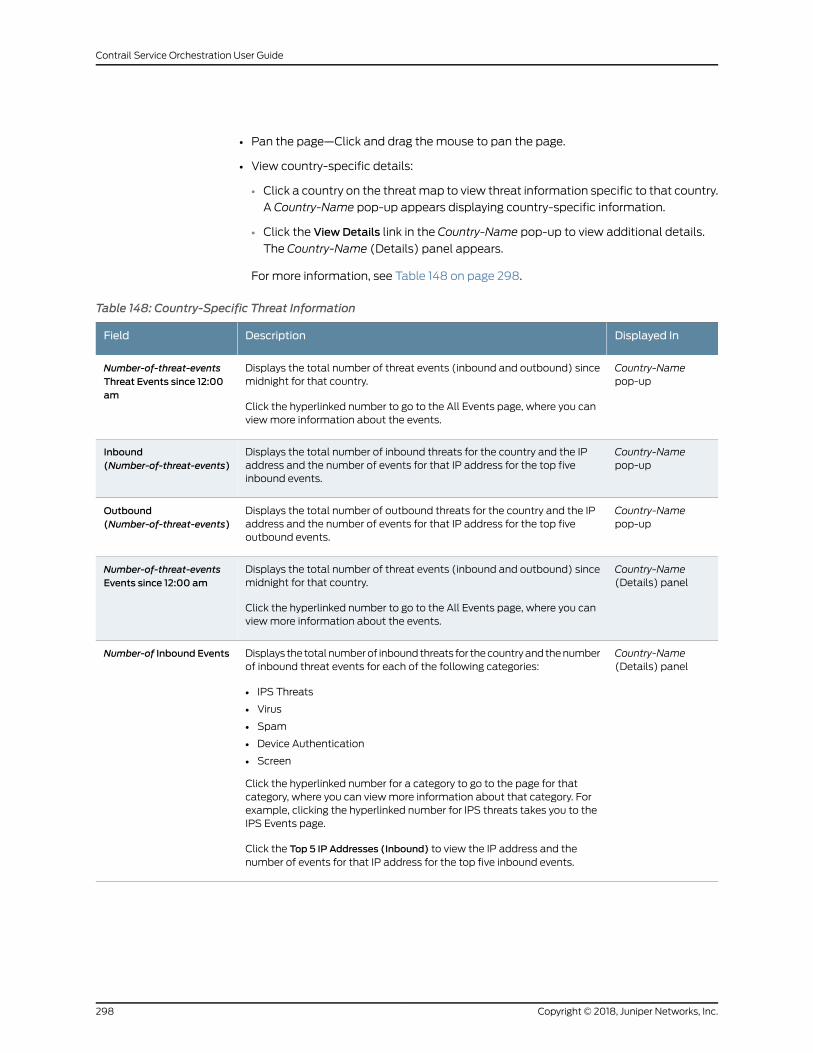
• Pan the page—Click and drag the mouse to pan the page.
• View country-specific details:
• Click a country on the threatmap to view threat information specific to that country.
A Country-Name pop-up appears displaying country-specific information.
• Click the View Details link in the Country-Name pop-up to view additional details.
The Country-Name (Details) panel appears.
For more information, see Table 148 on page 298.
Table 148: Country-Specific Threat Information
Displayed InDescriptionField
Country-Namepop-up
Displays the total number of threat events (inbound and outbound) sincemidnight for that country.
Click the hyperlinked number to go to the All Events page, where you canviewmore information about the events.
Number-of-threat-eventsThreat Events since 12:00am
Country-Namepop-up
Displays the total number of inbound threats for the country and the IPaddress and the number of events for that IP address for the top fiveinbound events.
Inbound(Number-of-threat-events)
Country-Namepop-up
Displays the total number of outbound threats for the country and the IPaddress and the number of events for that IP address for the top fiveoutbound events.
Outbound(Number-of-threat-events)
Country-Name(Details) panel
Displays the total number of threat events (inbound and outbound) sincemidnight for that country.
Click the hyperlinked number to go to the All Events page, where you canviewmore information about the events.
Number-of-threat-eventsEvents since 12:00 am
Country-Name(Details) panel
Displays the totalnumberof inboundthreats for thecountryandthenumberof inbound threat events for each of the following categories:
• IPS Threats
• Virus
• Spam
• Device Authentication
• Screen
Click the hyperlinked number for a category to go to the page for thatcategory, where you can viewmore information about that category. Forexample, clicking the hyperlinked number for IPS threats takes you to theIPS Events page.
Click the Top 5 IP Addresses (Inbound) to view the IP address and thenumber of events for that IP address for the top five inbound events.
Number-of Inbound Events
Copyright © 2018, Juniper Networks, Inc.298
Contrail Service Orchestration User Guide
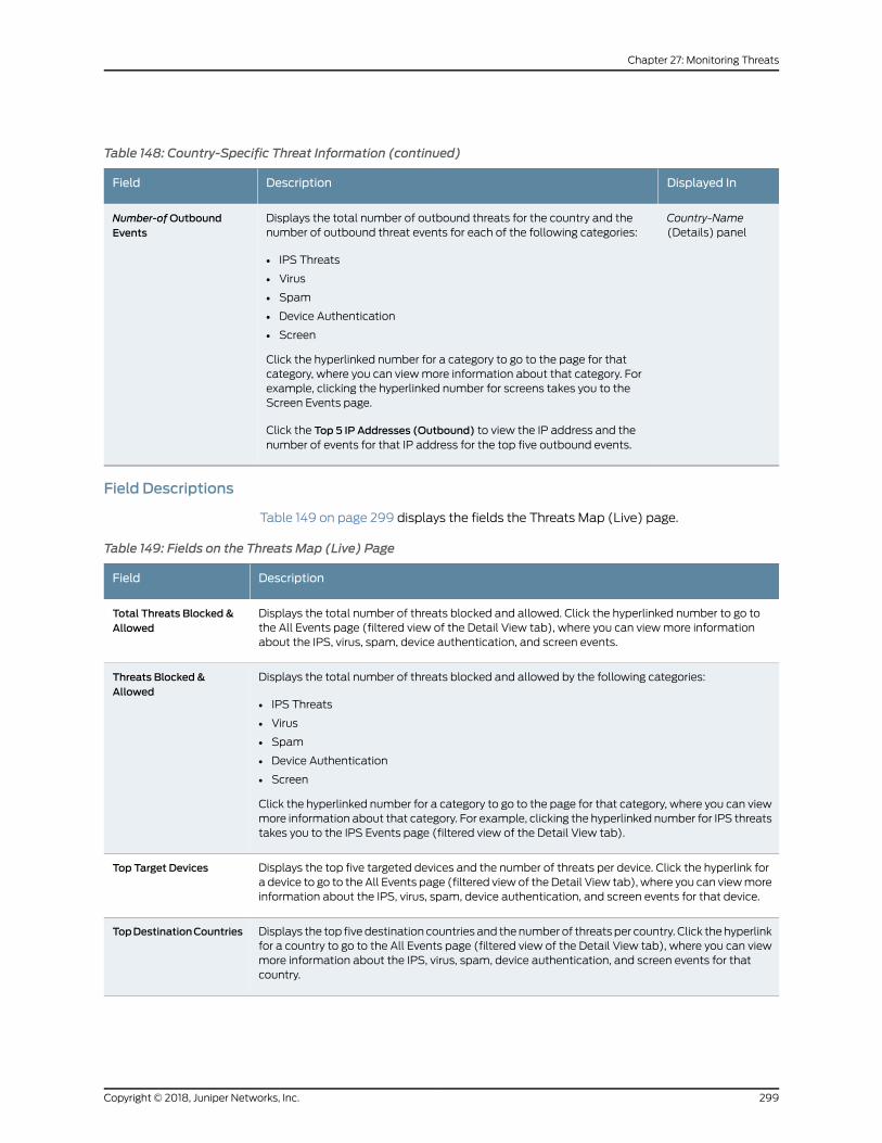
Table 148: Country-Specific Threat Information (continued)
Displayed InDescriptionField
Country-Name(Details) panel
Displays the total number of outbound threats for the country and thenumber of outbound threat events for each of the following categories:
• IPS Threats
• Virus
• Spam
• Device Authentication
• Screen
Click the hyperlinked number for a category to go to the page for thatcategory, where you can viewmore information about that category. Forexample, clicking the hyperlinked number for screens takes you to theScreen Events page.
Click the Top 5 IP Addresses (Outbound) to view the IP address and thenumber of events for that IP address for the top five outbound events.
Number-ofOutboundEvents
Field Descriptions
Table 149 on page 299 displays the fields the Threats Map (Live) page.
Table 149: Fields on the Threats Map (Live) Page
DescriptionField
Displays the total number of threats blocked and allowed. Click the hyperlinked number to go tothe All Events page (filtered view of the Detail View tab), where you can viewmore informationabout the IPS, virus, spam, device authentication, and screen events.
Total Threats Blocked &Allowed
Displays the total number of threats blocked and allowed by the following categories:
• IPS Threats
• Virus
• Spam
• Device Authentication
• Screen
Click the hyperlinked number for a category to go to the page for that category, where you can viewmore information about that category. For example, clicking the hyperlinked number for IPS threatstakes you to the IPS Events page (filtered view of the Detail View tab).
Threats Blocked &Allowed
Displays the top five targeted devices and the number of threats per device. Click the hyperlink fora device to go to the All Events page (filtered view of the Detail View tab), where you can viewmoreinformation about the IPS, virus, spam, device authentication, and screen events for that device.
Top Target Devices
Displays the top fivedestination countries and thenumber of threats per country. Click thehyperlinkfor a country to go to the All Events page (filtered view of the Detail View tab), where you can viewmore information about the IPS, virus, spam, device authentication, and screen events for thatcountry.
TopDestinationCountries
299Copyright © 2018, Juniper Networks, Inc.
Chapter 27: Monitoring Threats
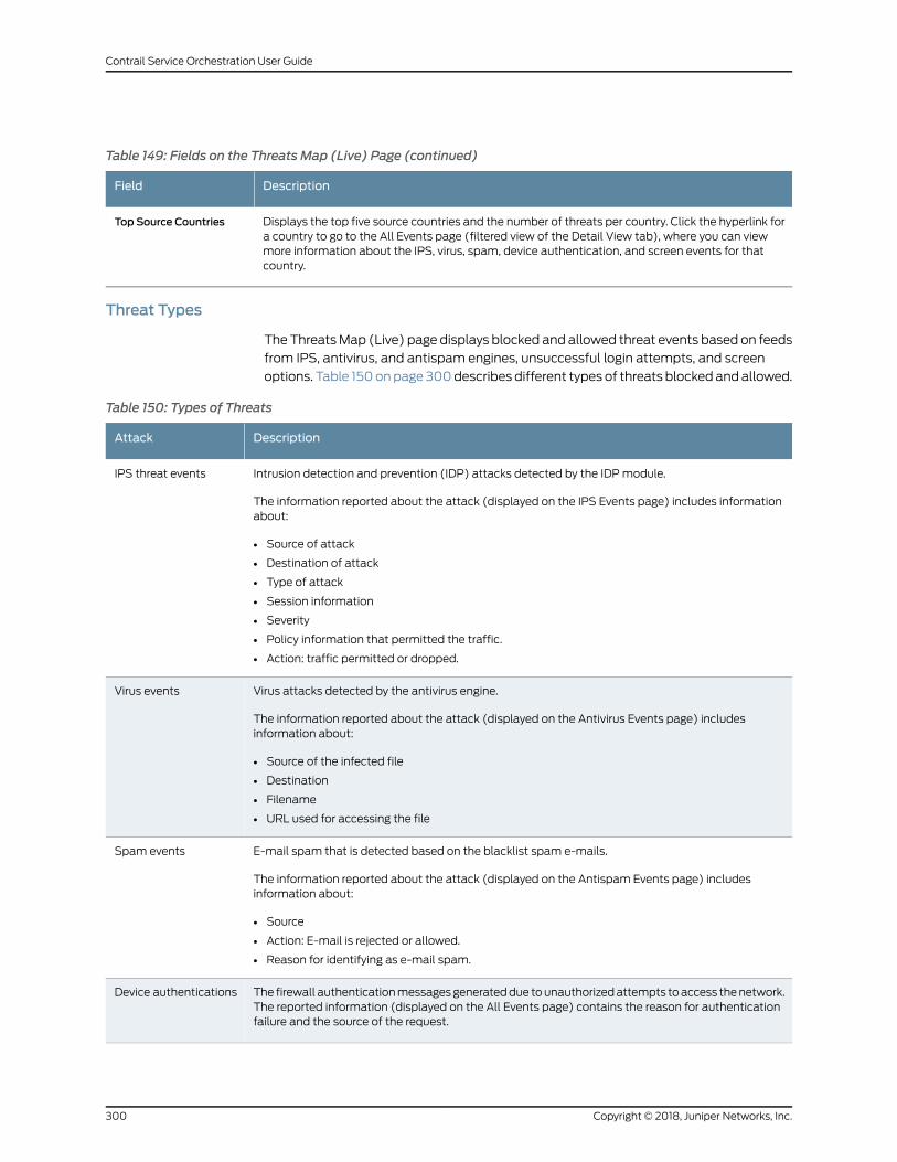
Table 149: Fields on the Threats Map (Live) Page (continued)
DescriptionField
Displays the top five source countries and the number of threats per country. Click the hyperlink fora country to go to the All Events page (filtered view of the Detail View tab), where you can viewmore information about the IPS, virus, spam, device authentication, and screen events for thatcountry.
Top Source Countries
Threat Types
TheThreatsMap (Live) page displays blocked and allowed threat events based on feeds
from IPS, antivirus, and antispam engines, unsuccessful login attempts, and screen
options. Table 150onpage 300describes different types of threats blocked andallowed.
Table 150: Types of Threats
DescriptionAttack
Intrusion detection and prevention (IDP) attacks detected by the IDPmodule.
The information reported about the attack (displayed on the IPS Events page) includes informationabout:
• Source of attack
• Destination of attack
• Type of attack
• Session information
• Severity
• Policy information that permitted the traffic.
• Action: traffic permitted or dropped.
IPS threat events
Virus attacks detected by the antivirus engine.
The information reported about the attack (displayed on the Antivirus Events page) includesinformation about:
• Source of the infected file
• Destination
• Filename
• URL used for accessing the file
Virus events
E-mail spam that is detected based on the blacklist spam e-mails.
The information reported about the attack (displayed on the Antispam Events page) includesinformation about:
• Source
• Action: E-mail is rejected or allowed.
• Reason for identifying as e-mail spam.
Spam events
The firewall authenticationmessagesgenerateddue tounauthorizedattempts toaccess thenetwork.The reported information (displayed on the All Events page) contains the reason for authenticationfailure and the source of the request.
Device authentications
Copyright © 2018, Juniper Networks, Inc.300
Contrail Service Orchestration User Guide
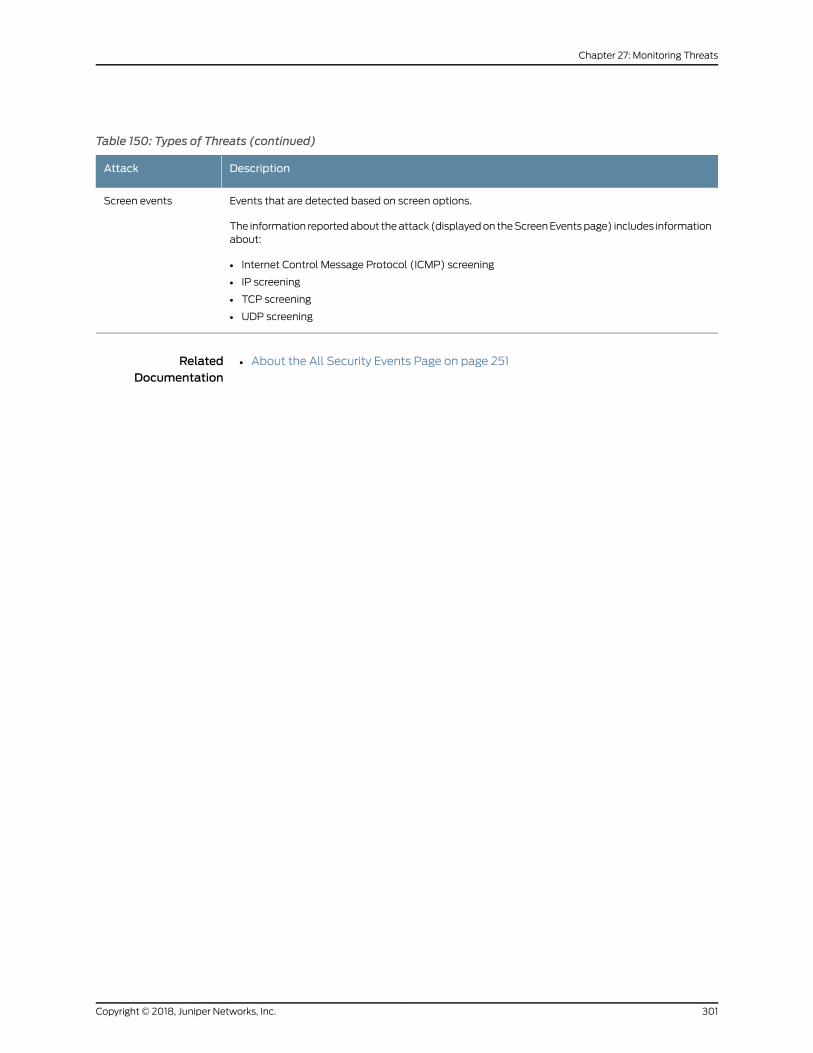
Table 150: Types of Threats (continued)
DescriptionAttack
Events that are detected based on screen options.
The information reportedabout theattack (displayedon theScreenEventspage) includes informationabout:
• Internet Control Message Protocol (ICMP) screening
• IP screening
• TCP screening
• UDP screening
Screen events
RelatedDocumentation
• About the All Security Events Page on page 251
301Copyright © 2018, Juniper Networks, Inc.
Chapter 27: Monitoring Threats

Copyright © 2018, Juniper Networks, Inc.302
Contrail Service Orchestration User Guide
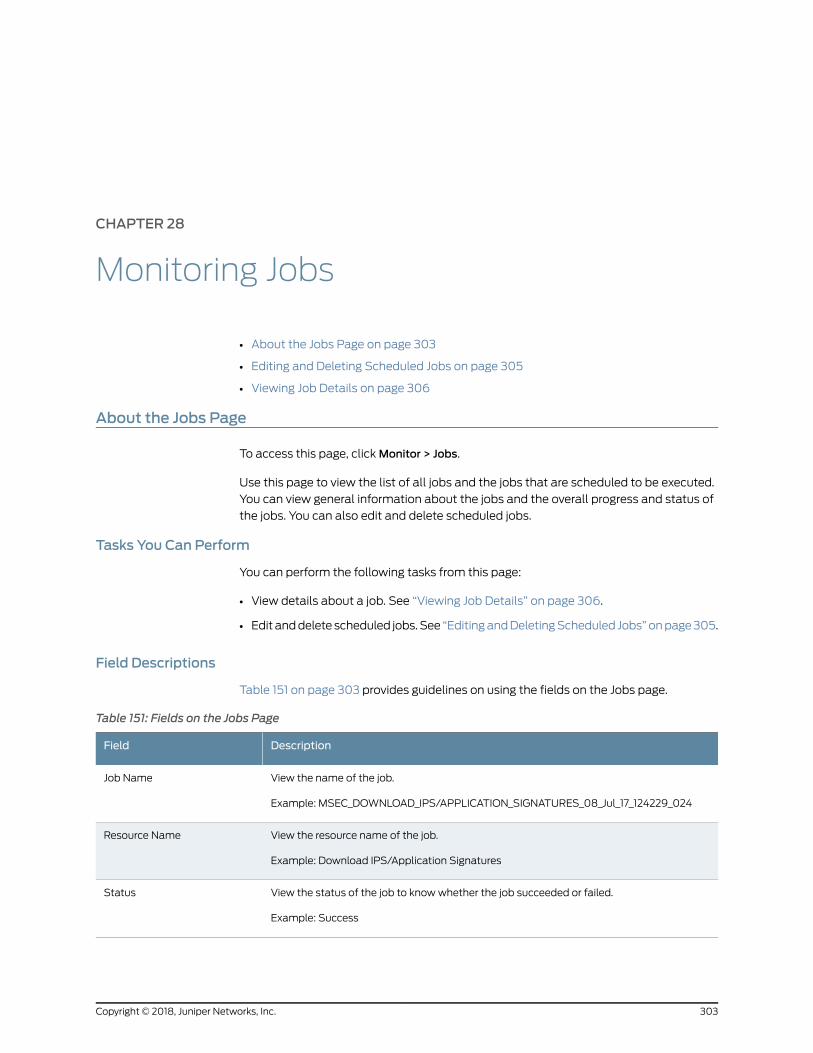
CHAPTER 28
Monitoring Jobs
• About the Jobs Page on page 303
• Editing and Deleting Scheduled Jobs on page 305
• Viewing Job Details on page 306
About the Jobs Page
To access this page, clickMonitor > Jobs.
Use this page to view the list of all jobs and the jobs that are scheduled to be executed.
You can view general information about the jobs and the overall progress and status of
the jobs. You can also edit and delete scheduled jobs.
Tasks You Can Perform
You can perform the following tasks from this page:
• View details about a job. See “Viewing Job Details” on page 306.
• Edit anddelete scheduled jobs.See “EditingandDeletingScheduled Jobs”onpage305.
Field Descriptions
Table 151 on page 303 provides guidelines on using the fields on the Jobs page.
Table 151: Fields on the Jobs Page
DescriptionField
View the name of the job.
Example: MSEC_DOWNLOAD_IPS/APPLICATION_SIGNATURES_08_Jul_17_124229_024
Job Name
View the resource name of the job.
Example: Download IPS/Application Signatures
Resource Name
View the status of the job to knowwhether the job succeeded or failed.
Example: Success
Status
303Copyright © 2018, Juniper Networks, Inc.
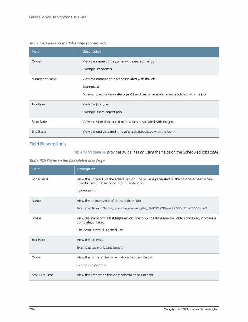
Table 151: Fields on the Jobs Page (continued)
DescriptionField
View the name of the owner who created the job.
Example: cspadmin
Owner
View the number of tasks associated with the job.
Example: 2
For example, the tasks site.ucpe-32 and customer.sdwan are associated with the job.
Number of Tasks
View the job type.
Example: tssm import pop
Job Type
View the start date and time of a task associated with the job.Start Date
View the end date and time of a task associated with the job.End State
Field Descriptions
Table 19 on page 46 provides guidelines on using the fields on the Scheduled Jobs page.
Table 152: Fields on the Scheduled Jobs Page
DescriptionField
View the unique ID of the scheduled job. The value is generated by the database when a newschedule record is inserted into the database.
Example: 48
Schedule ID
View the unique name of the scheduled job.
Example: Tenant Delete_csp.tssm_remove_site_e340354716ae43859fad5ba15669eee2
Name
View the statusof the last triggered job. The following statesareavailable: scheduled, In progress,complete, or failed.
The default status is scheduled.
Status
View the job type.
Example: tssm onboard tenant
Job Type
View the name of the owner who scheduled the job.
Example: cspadmin
Owner
View the time when the job is scheduled to run next.Next Run Time
Copyright © 2018, Juniper Networks, Inc.304
Contrail Service Orchestration User Guide
RelatedDocumentation
Editing and Deleting Scheduled Jobs on page 305•
Editing and Deleting Scheduled Jobs
You can edit and delete scheduled jobs. This topic contains the following sections:
• Editing Scheduled Jobs on page 305
• Deleting Scheduled Jobs on page 305
Editing Scheduled Jobs
You canmodify the date and time of deployment of scheduled jobs.
Tomodify a scheduled job:
1. SelectMonitor > Jobs > Scheduled Jobs.
The Scheduled Jobs page appears.
2. Select the job that you want to reschedule the deployment, and click the edit icon.
The Edit Schedule page appears.
3. To execute the job immediately, delete the existing scheduled entry, create a new
entry, and then select the Run now option. To reschedule the job for a later date and
time, or select the Schedule at a later time option.
4. Click Save to save the changes.
Themodified job and its details are displayed on a page
Deleting Scheduled Jobs
You can delete one or more scheduled jobs.
To delete a scheduled job:
1. SelectMonitor > Jobs> Scheduled Jobs.
The Scheduled Jobs page appears with a list of jobs.
2. Select the check box of the job that you want to delete and then click the delete icon
(X).
The Confirm Delete page appears.
3. Click Yes to confirm.
The scheduled job is deleted.
305Copyright © 2018, Juniper Networks, Inc.
Chapter 28: Monitoring Jobs
RelatedDocumentation
About the Jobs Page on page 303•
• Viewing Job Details on page 306
Viewing Job Details
You can use the Detailed View page to view all the parameters of a job.
To view details of a job:
• Right-click the job name that you want to see the detailed view for and select Detail
View, or select the job and click More > Detail View.
• Alternatively, hover over the job name and click the Detailed View icon that appears
before it.
The Detailed View page appears, showing the details of the job and the number of tasks
associated with the job. See the relevant topic “About the Jobs Page” on page 303 for a
description of the fields on these pages.
RelatedDocumentation
• About the Jobs Page on page 303
Copyright © 2018, Juniper Networks, Inc.306
Contrail Service Orchestration User Guide
CHAPTER 29
Managing Devices
• Multidepartment CPE Device Support on page 307
• About the Devices Page on page 308
• Performing Return Material Authorization (RMA) for a Single-CPE Device on page 310
• Performing Return Material Authorization (RMA) for Dual-CPE Devices on page 312
• Granting RMA for a Device on page 315
• Managing a Single CPE Device on page 319
• Rebooting a CPE Device on page 320
Multidepartment CPE Device Support
Multitenancy enables a single NFX Series device to bemapped to serve across multiple
departments within a single tenant. Each department has its own Layer 3 VPN and all
Layer 3 VPNs are carried over to the hub using a shared overlay. The traffic is segregated
to each department. A single overlay of IPsec or generic routing encapsulation (GRE)
tunnels is used to carry all department traffic from the site through MPLS-based traffic
separation.
Multitenancy is acost-effectiveapproachwhere thecostof adeviceand itsmaintenance
is sharedamongmultipledepartmentsacrossa tenant.Withmultitenantdevice support,
a dedicated share of the device is allocated to each department, and the data is kept
private from the other tenants that access the same device.
NOTE: Only users with the Tenant Administrator role have access to theCustomer Portal GUI.
The tenant administrator can perform the following tasks:
• Manage andmonitor all policies and dashboards for all departments.
• Manage applications in the dashboard for each tenant.
• Create SD-WAN and security policies for each tenant andmonitor the dashboard at
the site level or at the department level.
307Copyright © 2018, Juniper Networks, Inc.
• View or select SD-WAN or security services on the shared CPE device through the
management portal.
• View the shared CPE device and its services and networks even though theWAN links
might be shared bymultiple departments.
The service provider administrator can see all departments within the CPE device and
activate the device.
RelatedDocumentation
About the SLA Performance of a Single Tenant Page on page 283•
• Viewing the SLA Performance of a Site on page 285
About the Devices Page
To access this page, click Resources > Devices.
You can use the Devices page to view the list of available CPE devices at the customer
premises. You can also view information about each CPE device in the network.
Tasks You Can Perform
You can perform the following tasks from this page:
• Quickly view activation data created for CPEs in the widgets that appear at the top of
the page. See Table 45 on page 92.
• Manage a single CPE. See “Managing a Single CPE Device” on page 319.
• Reboot a CPE device. See Rebooting a CPE Device.
• Perform Return Material Authorization (RMA) to replace a device that is faulty or not
reachable. You can perform RMA for a single-CPE or a dual-CPE device.
• For information on performing RMA on single-CPE devices, see “Performing Return
Material Authorization (RMA) for a Single-CPE Device” on page 310
• For information on performing RMA on dual-CPE devices, see “Performing Return
Material Authorization (RMA) for Dual-CPE Devices” on page 312
• View details about a CPE . Click the details icon that appears when you hover over the
name of a device or clickMore > Details. See “Viewing Object Details” on page 241.
• Show or hide columns about the CPE. See “Sorting Objects” on page 241.
• Search an object about the CPE. See “Searching for Text in an Object Data Table” on
page 242.
Field Descriptions
• Table 45 on page 92 describes widgets on the Devices page.
• Table 46 on page 92 describes the fields on the Devices page.
Copyright © 2018, Juniper Networks, Inc.308
Contrail Service Orchestration User Guide
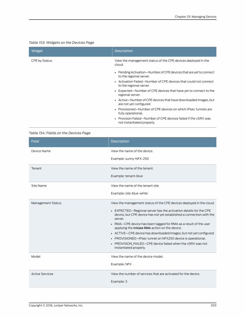
Table 153: Widgets on the Devices Page
DescriptionWidget
View themanagement status of the CPE devices deployed in thecloud.
• PendingActivation—NumberofCPEdevices thatareyet toconnectto the regional server.
• Activation Failed—Number of CPE devices that could not connectto the regional server.
• Expected—Number of CPE devices that have yet to connect to theregional server.
• Active—Number ofCPEdevices that havedownloaded images, butare not yet configured.
• Provisioned—Number of CPE devices on which IPsec tunnels arefully operational.
• Provision Failed—Number of CPE devices failed if the vSRX wasnot instantiated properly.
CPE by Status
Table 154: Fields on the Devices Page
DescriptionField
View the name of the device.
Example: sunny-NFX-250
Device Name
View the name of the tenant.
Example: tenant-blue
Tenant
View the name of the tenant site.
Example: site-blue-white
Site Name
View themanagement status of the CPE devices deployed in the cloud.
• EXPECTED—Regional server has the activation details for the CPEdevice, but CPE device has not yet established a connection with theserver.
• RMA—CPE device has been tagged for RMA as a result of the userapplying the Initiate RMA action on the device.
• ACTIVE—CPEdevice has downloaded images, but not yet configured.
• PROVISIONED—IPsec tunnel on NFX250 device is operational.
• PROVISION_FAILED—CPE device failed when the vSRXwas notinstantiated properly.
Management Status
View the name of the device model.
Example: NFX
Model
View the number of services that are activated for the device.
Example: 3
Active Services
309Copyright © 2018, Juniper Networks, Inc.
Chapter 29: Managing Devices
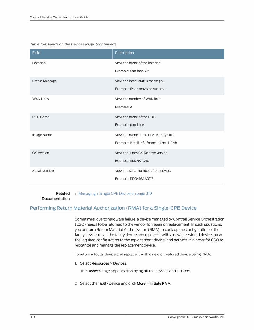
Table 154: Fields on the Devices Page (continued)
DescriptionField
View the name of the location.
Example: San Jose, CA
Location
View the latest status message.
Example: IPsec provision success
Status Message
View the number of WAN links.
Example: 2
WAN Links
View the name of the POP.
Example: pop_blue
POP Name
View the name of the device image file.
Example: install_nfx_fmpm_agent_1_0.sh
Image Name
View the Junos OS Release version.
Example: 15.1X49-D40
OS Version
View the serial number of the device.
Example: DD0416AA0117
Serial Number
RelatedDocumentation
Managing a Single CPE Device on page 319•
Performing ReturnMaterial Authorization (RMA) for a Single-CPE Device
Sometimes, due to hardware failure, a devicemanagedbyContrail ServiceOrchestration
(CSO) needs to be returned to the vendor for repair or replacement. In such situations,
you perform Return Material Authorization (RMA) to back up the configuration of the
faulty device, recall the faulty device and replace it with a new or restored device, push
the required configuration to the replacement device, and activate it in order for CSO to
recognize andmanage the replacement device.
To return a faulty device and replace it with a new or restored device using RMA:
1. Select Resources > Devices.
The Devices page appears displaying all the devices and clusters.
2. Select the faulty device and clickMore > Initiate RMA.
Copyright © 2018, Juniper Networks, Inc.310
Contrail Service Orchestration User Guide
A confirmation page appears requesting for confirmation to go aheadwith the initiate
RMA process for the device. Click Yes to confirm RMA for device.
Click No to cancel the process
NOTE:• The Initiate RMA option is enabled for a device only if themanagement
status is PROVISIONED.
• In the Sites > Site Management page, the Site Status for the device for
which you performed Initiate RMA, will remain PROVISIONED, however,
you will see a red colored RMA tag beside the current status to indicate
that RMA has been initiated for this device.
If you click Yes, the RMAprocess is initiated for the selected device. Themanagement
status of the device changes to RMA. Once you put a device in the RMA state, you
have to start theprocessgettinga replacement for thedevice. This action is performed
outside of CSO.
3. After you receive the replacementof thedevice, provide thedetailsof the replacement
device by clickingMore > Grant RMA. See “Granting RMA for a Device” on page 315.
NOTE: The Grant RMA option is enabled only if themanagement status
is RMA.
4. To activate the device, select the device and clickActivateDevice. Enter theActivation
Code of the device to activate the device for usage. When the device is activated, its
Management Status changes to PROVISIONED.
5. To complete the RMA process, youmust manually push the following configuration
to the newly provisioned device:
NOTE:• In SD-WAN deployments, once the new device is in the PROVISIONED
state, you can proceed to configure the device bymanually pushingapplication signatures, certificates, and policies.
• In hybridWAN deployments, service chains will be restoredautomatically.
• Licenses—If the replaced device is a physical SRX device, you need to generate a
new license and upload it.
• Application Signatures—Push the application signatures to the replaced device.
See “About the Application Signatures Page” on page 520.
311Copyright © 2018, Juniper Networks, Inc.
Chapter 29: Managing Devices
• Certificates—Import and install the required certificates on the replaceddevice. See
“Importing a Certificate” on page 619 and “Installing and Uninstalling Certificates”
on page 621.
• Policies—Push the defined firewall and NAT policies to the replaced device. See
“About the Firewall Policy Page” on page 344 and “About theNATPolicies Page” on
page 454.
After you complete these steps, theManagement Status of the replacement device
remains in PROVISIONED state. The RMA process is complete and the device is now
ready to be used.
RelatedDocumentation
About the Devices Page on page 308•
• Granting RMA for a Device on page 315
Performing ReturnMaterial Authorization (RMA) for Dual-CPE Devices
Sometimes, a single device or both the deviceswithin anNFX or SRX cluster fail, and has
to be replaced with a new or restored device(s). In such situations, you perform RMA to
back-up the configuration of the faulty device(s), recall the faulty device and replace it
with a new or restored device(s), push the required configuration to the replacement
device(s), and activate the device(s) in order for CSO to recognize andmanage the
replacement device(s).
The following section discuss how you can perform RMA for an NFX or SRX cluster:
• Performing RMA for an NFX Cluster on page 312
• Performing RMA for an SRX Cluster on page 314
Performing RMA for an NFX Cluster
You can only perform RMA for an NFX cluster at the cluster level. That is, you have to
perform RMA for both the devices in the NFX cluster even if only a single device in the
cluster has failed.
NOTE: You cannot select an individual device in theNFXcluster andperformRMA for it.
To perform RMA for an NFX cluster:
1. Select Resources > Devices.
The Devices page appears displaying all the devices and clusters.
2. Select the NFX cluster for which you want to perform RMA and clickMore > Initiate
RMA.
A confirmation page appears requesting for confirmation to go aheadwith the initiate
RMAprocess for theselectedNFXcluster. ClickYes toconfirmRMAfor theNFXcluster.
Copyright © 2018, Juniper Networks, Inc.312
Contrail Service Orchestration User Guide
Click No to cancel the process.
NOTE:• The Initiate RMA option is enabled for an NFX cluster only if the
management status is PROVISIONED.
• In the Sites > Site Management page, the Site Status for the NFX cluster
for which you performed Initiate RMA, will remain PROVISIONED,
however, you will see a red colored RMA tag beside the current status
to indicate that RMA has been initiated for this device.
If you click Yes, the RMA process is initiated for the selected NFX cluster. The
Management Status of the device changes to RMA.
After the NFX cluster is in the RMA state, you can raise a device replacement request
for the faulty device(s) in the NFX cluster. This action is performed outside of CSO.
3. After you receive the replacement of the device(s), you have to provide the details of
both thedevices in theNFXcluster toCSO,byclickingMore>GrantRMA. See “Granting
RMA for a Device” on page 315.
NOTE: The Grant RMA option is enabled only if themanagement status
is RMA.
4. To activate the devices within the NFX cluster, select the cluster and click Activate
Device. Enter the Activation Code for the primary and secondary devices to activate
thedevicesof theNFXcluster for usage.When thedevice is activated, itsManagement
Status changes to PROVISIONED.
5. To complete the RMA process, youmust manually push the following configuration
to the newly provisioned devices:
NOTE:• InSD-WANdeployments,once thenewdevicesare in thePROVISIONED
state, you can proceed to configure the devices bymanually pushingapplication signatures, certificates, and policies.
• In hybridWAN deployments, service chains are restored automatically.
• Application Signatures—Push the application signatures to the replaced device.
See “About the Application Signatures Page” on page 520.
• Certificates—Import and install the required certificates on the replaced devices.
See “ImportingaCertificate”onpage619and“InstallingandUninstallingCertificates”
on page 621.
313Copyright © 2018, Juniper Networks, Inc.
Chapter 29: Managing Devices
• Policies—Push the defined firewall and NAT policies to the replaced devices. See
“About the Firewall Policy Page” on page 344 and “About theNATPolicies Page” on
page 454.
The RMA process is complete and the device(s) in the NFX cluster are now ready to be
used.
Performing RMA for an SRX Cluster
For an SRX cluster, you can perform RMA on amember device of the cluster. That is, you
can select the faulty device from the SRX cluster and perform RMA on it individually.
NOTE: For the CSORelease 3.3, you cannot perform the RMA process for anSRX cluster at the cluster level.
To return a faulty device within an SRX cluster and replace it with a new or restored
device using RMA:
1. Select Resources > Devices.
The Devices page appears displaying all the devices and clusters.
2. Select the faulty device within the SRX cluster and clickMore > Initiate RMA.
A confirmation page appears requesting for confirmation to go aheadwith the initiate
RMA process for the device. Click Yes to confirm RMA for device.
Click No to cancel the process.
NOTE:• The Initiate RMA option is enabled for a device only if themanagement
status is PROVISIONED.
• In the Sites > Site Management page, the Site Status for the device for
which you performed Initiate RMA, will remain PROVISIONED, however,
you will see a red colored RMA tag beside the current status to indicate
that RMA has been initiated for this device.
If you click Yes, the RMAprocess is initiated for the selected device. Themanagement
status of the device changes toRMA. Once you put a device in the RMA state, you can
raise a device replacement request for the faulty device in the SRX cluster. This action
is performed outside of CSO.
3. After you receive the replacementof thedevice, provide thedetailsof the replacement
device by clickingMore > Grant RMA. See “Granting RMA for a Device” on page 315.
NOTE: The Grant RMA option is enabled only if themanagement status
is RMA.
Copyright © 2018, Juniper Networks, Inc.314
Contrail Service Orchestration User Guide
After you complete these steps, theManagement Status of the replacement device(s)
is changed to PROVISIONED state. The RMA process is complete and the device is now
ready to be used.
RelatedDocumentation
About the Devices Page on page 308•
• Performing Return Material Authorization (RMA) for a Single-CPE Device on page 310
• Granting RMA for a Device on page 315
Granting RMA for a Device
• Granting RMA for a Single-CPE Device on page 315
• Granting RMA for a Dual-CPE Device on page 316
• Granting RMA for an SRX Device within an SRX Cluster on page 318
Granting RMA for a Single-CPE Device
Before you perform Grant RMA for a Device, ensure that:
• You have received the replacement of the faulty device.
• You have the serial number and the activation code of the replacement device.
To perform Grant RMA for a device:
1. Select Resources > Devices.
The Devices page appears displaying all the devices and clusters.
2. Select the defective device that you have already performed RMA for and clickMore
> Grant RMA.
The Grant RMA for Device page appears.
NOTE: TheGrant RMA option is only enabled if theManagement Status of
the device is RMA.
3. Complete the configuration according to the guidelines provided in
Table 155 on page 316.
4. ClickOK to perform the grant RMA process.
When you perform Grant RMA for a device, a job is created to perform the following
tasks:
• Thedevice relatedconfiguration isbacked-up to theCSOdatabase, and theexisting
device is recalled and the new or restored device is added to the network.
• Themanagement status of the device changes to Expected in the Devices page.
315Copyright © 2018, Juniper Networks, Inc.
Chapter 29: Managing Devices
In the Sites > Site Management page, the Site Status for the device for which you
performed Grant RMA, changes to Expected.
NOTE: Youcan see theprogress of this job in theMonitor> Jobspage. This
jobmight take around 15minutes to complete.
To complete the RMA process and start using the new device, youmust activate the
device using the Activate Device option. See step 5 in “Performing Return Material
Authorization (RMA) for a Single-CPE Device” on page 310.
Table 155 on page 316 provides guidelines on using the fields on theGrantRMA forDevice
panel.
Table 155: Fields on the Grant RMA for Single-CPE Device Page
DescriptionField
Displays the name of the tenant who is performing RMA.Tenant Name
Displays the name of site in which the faulty device is present.Site Name
Displays the name of the faulty device that will be replaced with a new one through the GrantRMA process.
Device Name
Enter theserial numberof the replacementdevice. Theserial number is casesensitive. Example:DD2316AF0177
Serial Number
Enter the activation code for the replacement device. Youwill receive the activation code fromthe service provider, outside of CSO. Example: 545454
Activation Code
Granting RMA for a Dual-CPE Device
Before you perform Grant RMA for a Device, ensure that:
• You have received the replacement of the faulty device(s).
• Youhave theserial number(s)and theactivationcode(s)of the replacementdevice(s).
To perform Grant RMA for a cluster:
1. Select Resources > Devices.
The Devices page appears displaying all the devices and clusters.
2. Select the cluster that you have already performed RMA for and clickMore > Grant
RMA.
The Grant RMA for Device page appears.
Copyright © 2018, Juniper Networks, Inc.316
Contrail Service Orchestration User Guide
NOTE: TheGrant RMA option is only enabled if theManagement Status of
the device is RMA.
3. Complete the configuration according to the guidelines provided in
Table 156 on page 317.
4. ClickOK to complete the grant RMA process.
When you perform Grant RMA, the following actions are performed:
• Thecluster relatedconfiguration isbacked-up to theCSOdatabase, and thedevices
in the cluster are recalled and the new or restored device(s) are added to the
network.
• Themanagement status of the cluster changes to Expected in the Devices page.
In the Sites > Site Management page, the Site Status for the cluster for which you
performed Grant RMA, changes to Expected.
NOTE: Youcan see theprogress of this job in theMonitor> Jobspage. This
jobmight take around 15minutes to complete.
Table 156 on page 317 provides guidelines on using the fields on theGrant RMA for Device
panel.
Table 156: Fields on the Grant RMA for Dual-CPE Device Page
DescriptionField
Displays the name of the tenant who is performing RMA.Tenant Name
Displays the name of site in which the faulty device is present.Site Name
Displays thenameof the faultydevicecluster thatwill be replacedwithnewor restoreddevicesthrough the Grant RMA process.
Device Name
Enter the serial number of the primary replacement device. The serial number is case sensitive.Example: DD2316AF0177
Primary Serial Number
Enter the activation code for the primary replacement device. You will receive the activationcode from the service provider, outside of CSO. Example: 545454
Primary Activation Code
Enter the serial number of the secondary replacement device. The serial number is casesensitive. Example: DD2316AF0145
Secondary Serial Number
Enter the activation code for the secondary replacement device. Youwill receive the activationcode from the service provider, outside of CSO. Example: 545476
Secondary Activation Code
317Copyright © 2018, Juniper Networks, Inc.
Chapter 29: Managing Devices
Granting RMA for an SRX Device within an SRX Cluster
Before you perform Grant RMA for a Device, ensure that:
• You have received the replacement of the faulty device.
• You have the serial number and the activation code of the replacement device.
To perform Grant RMA for a device:
1. Select Resources > Devices.
The Devices page appears displaying all the devices and clusters.
2. Select the defective device that you have already performed RMA for and clickMore
> Grant RMA.
The Grant RMA for Device page appears.
NOTE: TheGrant RMA option is only enabled if theManagement Status of
the device is RMA.
3. Complete the configuration according to the guidelines provided in
Table 157 on page 318.
4. ClickOK to perform the grant RMA process.
When you perform Grant RMA for a device, a job is created to perform the following
tasks:
• The device object in CSO is updatedwith the serial number and activation code for
the replacement device.
• Themanagement status of the device is restored in the Devices page.
In the Sites > Site Management page, the Site Status for the device for which you
performed Grant RMA, changes to PROVISIONED.
NOTE: You can see the progress of this job in theMonitor > Jobs page.
Table 157 on page 318 provides guidelines on using the fields on theGrant RMA for Device
panel.
Table 157: Fields on the Grant RMA for Device Page (for SRX Device in an SRX Cluster)
DescriptionField
Displays the name of the tenant who is performing RMA.Tenant Name
Copyright © 2018, Juniper Networks, Inc.318
Contrail Service Orchestration User Guide
Table 157: Fields on the Grant RMA for Device Page (for SRX Device in an SRX Cluster) (continued)
DescriptionField
Displays the name of site in which the faulty device is present.Site Name
Displays the name of the faulty device that will be replaced with a new one through the GrantRMA process.
Device Name
Enter theserial numberof the replacementdevice. Theserial number is casesensitive. Example:DD2316AF0177
Serial Number
Enter the activation code for the replacement device. Youwill receive the activation code fromthe service provider, outside of CSO. Example: 545454
Activation Code
RelatedDocumentation
About the Devices Page on page 308•
• Performing Return Material Authorization (RMA) for a Single-CPE Device on page 310
• Performing Return Material Authorization (RMA) for Dual-CPE Devices on page 312
Managing a Single CPE Device
Youcanuse theDevicespage toviewandmanageasinglecustomerpremisesequipment
(CPE) device at the tenant site. To access this page, click Resources > Devices >
Device-Name.
You can perform the following tasks from this page:
• View the following information on the Overview tab:
• Geographical location of the device at the tenant site.
• Aggregate throughput of the device.
• Recent alerts for the device.
• Details of the device, such as serial number, management IP address, OS version,
device template, tenant name, site name, and site location.
• View the following information on the Policies tab:
• List of all policies applicable to a CPE device.
• Click a policy name to view the rules that are applicable for the CPE device.
• Click the edit icon at the end of the row to edit a policy. You are taken to the
Configuration > Policy page, where you can edit the policies.
• Details about the tenant user who last updated the policy.
• Time when the policy was last updated.
319Copyright © 2018, Juniper Networks, Inc.
Chapter 29: Managing Devices
• Deployment status of the policy.
• Number of rules applicable to the device compared to the total number of rules
applicable to the tenant.
RelatedDocumentation
About the Devices Page on page 308•
Rebooting a CPE Device
You need to reboot a CPE device if the device is down, or if all troubleshooting options
fail. A CPE device might be a tenant device or a cloud hub device.
To reboot a tenant device:
1. Select Resources > Tenant Devices.
2. Select the tenant device that you want to reboot and selectMore > Reboot.
ADeviceReboot job link is createdand theStatusMessagecolumndisplays the status
as Reboot in-progress.
NOTE: If you reboot a tenant device, deployments that are in progress arestopped.
3. (Optional) Click the Device Reboot link to view the device reboot logs.
4. (Optional) You can view the job status on theMonitor > Jobs page.
To reboot a cloud hub device:
1. Select Resources > Cloud Hub Devices.
2. Select the cloud hub device that you want to reboot and selectMore > Reboot.
ADeviceReboot job link is createdand theStatusMessagecolumndisplays the status
as Reboot in-progress.
NOTE: If you reboot a cloud hub device, deployments that are in progressare stopped.
3. (Optional) Click the Device Reboot link to view the device reboot logs.
4. (Optional) You can view the job status on theMonitor > Jobs page.
Copyright © 2018, Juniper Networks, Inc.320
Contrail Service Orchestration User Guide
You can view the status of reboot in the Status Message column.
On successful reboot of the CPE device, the Status Message column displays the status
as Reboot Succeeded.
If aCPEdevice isnot reachableor if the reboot timeexceeds the timeout value, the reboot
fails and the Status Message column displays the status as Reboot Failed.
NOTE: The timeout value for rebooting a CPE device is 14minutes.
RelatedDocumentation
• About the Cloud Hub Devices Page on page 94
• About the Tenant Devices Page on page 91
321Copyright © 2018, Juniper Networks, Inc.
Chapter 29: Managing Devices

Copyright © 2018, Juniper Networks, Inc.322
Contrail Service Orchestration User Guide
CHAPTER 30
Managing Device Images
• Device Images Overview on page 323
• About the Device Images Page on page 323
• Deleting Device Images on page 324
Device Images Overview
An imagemanagement system provides full lifecycle management of images for all
network devices, including CPE device and virtualized network function (VNF) images.
A device image is a software installation package for the CPE device or an image for a
virtual application that runs on the device. For example, for aNFXSeries device platform,
you require an NFX software image and a software image for the vSRX application that
provides security functions and routing on the device.
RelatedDocumentation
About the Device Images Page on page 323•
About the Device Images Page
To access this page, click Resources > Images.
Youcanuse the Imagespage to view the list of device images that areavailable in tenant’s
network.
Tasks You Can Perform
You can perform the following tasks from this page:
• View details about a device image. Click the details icon that appears when you hover
over the name of an image or clickMore > Details. See “Viewing Object Details” on
page 14.
• Show or hide columns about the device image. See “Sorting Objects” on page 15.
• Search an object for a device image. See “Searching for Text in an Object Data Table”
on page 15.
323Copyright © 2018, Juniper Networks, Inc.
Field Descriptions
Table 65 on page 126 shows the fields on the Images page.
Table 158: Fields on the Device Images Page
DescriptionField
View the name of the device image.
Example: juniper_srx_v1.tgz
Image Name
View the type of the device image.
Example: VNF Image
Type
View the version number of the device image.
Example: 1.1
Version
View the vendor name of the device.
Example: Juniper
Vendor
View the size of the device image.
Example: 14 KB
Size
RelatedDocumentation
Device Images Overview on page 323•
Deleting Device Images
You can delete one or more device images from the Device Images page.
To delete a device image:
1. Select Resources > Images.
The Images page appears with a list of device images.
2. Select the device image that you want to delete and then click the delete icon (X).
The Confirm Delete page appears.
3. Click Yes to confirm.
The Delete Successmessages is displayed.
The device image is deleted.
Copyright © 2018, Juniper Networks, Inc.324
Contrail Service Orchestration User Guide

RelatedDocumentation
• About the Device Images Page on page 323
325Copyright © 2018, Juniper Networks, Inc.
Chapter 30: Managing Device Images

Copyright © 2018, Juniper Networks, Inc.326
Contrail Service Orchestration User Guide
CHAPTER 31
Managing Network Services
• Network Service Overview on page 327
• About the Network Services Page on page 328
• About the Service Overview Page on page 329
• About the Service Instances Page on page 331
• Configuring VNF Properties on page 333
• vSRX VNF Configuration Settings on page 333
• LxCIPtable VNF Configuration Settings on page 337
• Cisco CSR-1000v VNF Configuration Settings on page 340
• Riverbed Steelhead VNF Configuration Settings on page 341
Network Service Overview
A network service is a final product offered to end users with a full description of its
functionality and specified performance.
Administrative users deploy network services between two locations in a virtual network,
so that traffic traveling in a specific direction on that link is subject to action from that
service. The term network service is defined in the ETSI Network Functions Virtualization
(NFV) standard.
A network service consists of a service chain of one or more linked network functions,
which are provided by specific virtualized network functions (VNFs), with a defined
direction for traffic flow and defined ingress and egress points. The term service chain
refers to the structure of a network service, and although not defined in the ETSI NFV
standard, this term is regularly used in NFV and software-defined networking (SDN).
A network service designer creates network services in Network Service Designer. When
the designer publishes the service to the network service catalog from Network Service
Designer, administrators can see the network service in Administration Portal.
RelatedDocumentation
About the Network Services Page on page 328•
• About the Service Overview Page on page 329
• About the Service Instances Page on page 331
327Copyright © 2018, Juniper Networks, Inc.
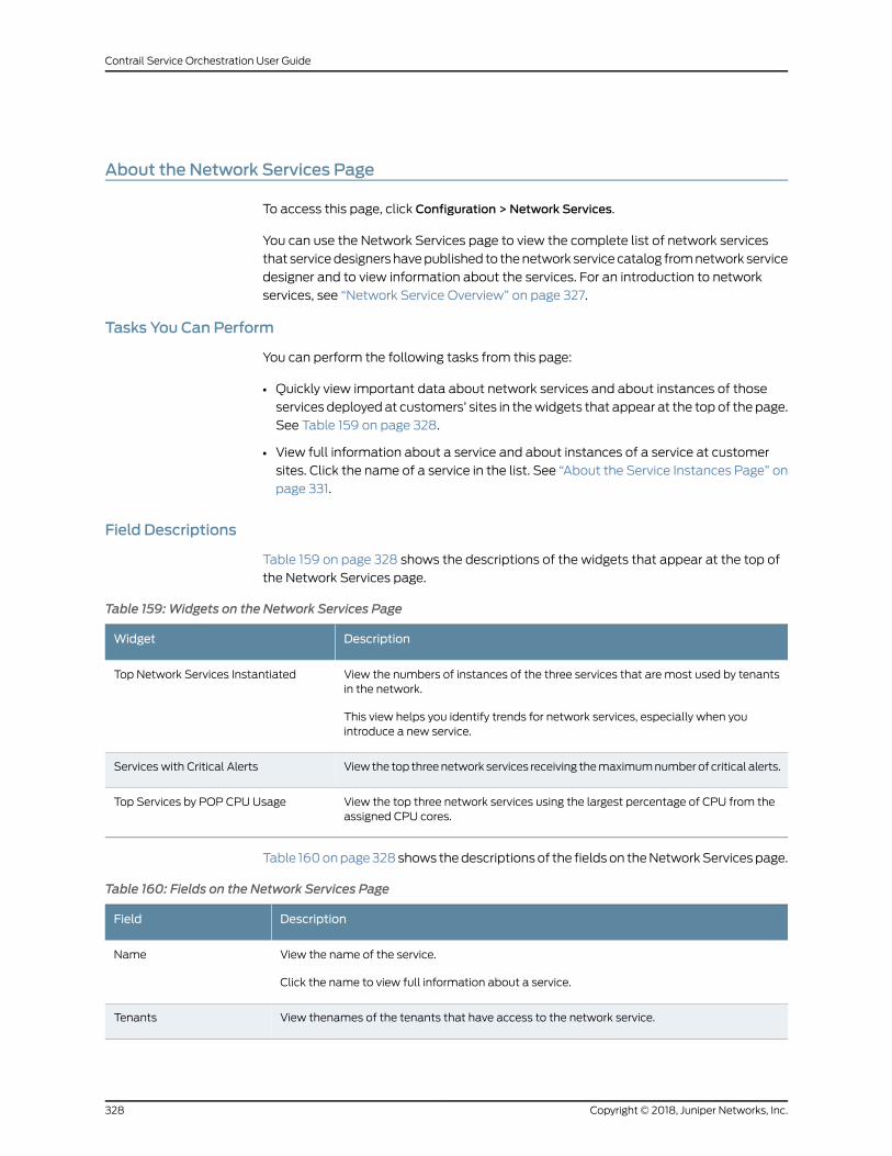
About the Network Services Page
To access this page, click Configuration > Network Services.
You can use the Network Services page to view the complete list of network services
that servicedesignershavepublished to thenetwork service catalog fromnetwork service
designer and to view information about the services. For an introduction to network
services, see “Network Service Overview” on page 327.
Tasks You Can Perform
You can perform the following tasks from this page:
• Quickly view important data about network services and about instances of those
services deployed at customers’ sites in thewidgets that appear at the top of the page.
See Table 159 on page 328.
• View full information about a service and about instances of a service at customer
sites. Click the name of a service in the list. See “About the Service Instances Page” on
page 331.
Field Descriptions
Table 159 on page 328 shows the descriptions of the widgets that appear at the top of
the Network Services page.
Table 159:Widgets on the Network Services Page
DescriptionWidget
View the numbers of instances of the three services that are most used by tenantsin the network.
This view helps you identify trends for network services, especially when youintroduce a new service.
Top Network Services Instantiated
View the top threenetwork services receiving themaximumnumberof critical alerts.Services with Critical Alerts
View the top three network services using the largest percentage of CPU from theassigned CPU cores.
Top Services by POP CPU Usage
Table 160onpage328shows thedescriptionsof the fieldson theNetworkServicespage.
Table 160: Fields on the Network Services Page
DescriptionField
View the name of the service.
Click the name to view full information about a service.
Name
View thenames of the tenants that have access to the network service.Tenants
Copyright © 2018, Juniper Networks, Inc.328
Contrail Service Orchestration User Guide
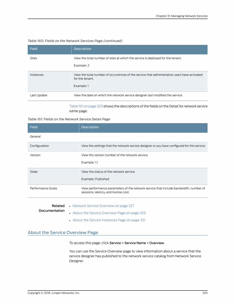
Table 160: Fields on the Network Services Page (continued)
DescriptionField
View the total number of sites at which the service is deployed for the tenant.
Example: 2
Sites
View the total number of occurrences of the service that administrative users have activatedfor the tenant.
Example: 1
Instances
View the date on which the network service designer last modified the service.Last Update
Table 161 onpage329shows thedescriptionsof the fieldson theDetail fornetwork service
name page.
Table 161: Fields on the Network Service Detail Page
DescriptionField
General
View the settings that the network service designer or you have configured for this service.Configuration
View the version number of the network service.
Example: 1.1
Version
View the status of the network service.
Example: Published
State
View performance parameters of the network service that include bandwidth, number ofsessions, latency, and license cost.
Performance Goals
RelatedDocumentation
Network Service Overview on page 327•
• About the Service Overview Page on page 329
• About the Service Instances Page on page 331
About the Service Overview Page
To access this page, click Service > Service Name >Overview.
You can use the Service Overview page to view information about a service that the
service designer has published to the network service catalog from Network Service
Designer.
329Copyright © 2018, Juniper Networks, Inc.
Chapter 31: Managing Network Services
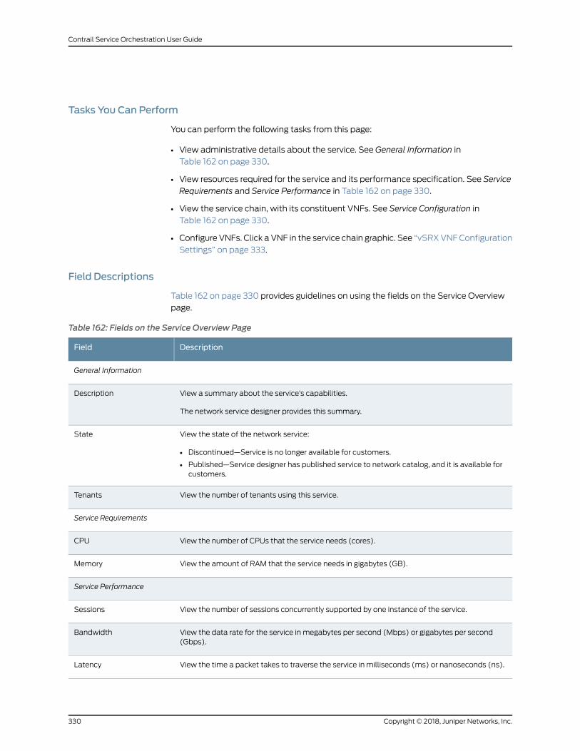
Tasks You Can Perform
You can perform the following tasks from this page:
• View administrative details about the service. See General Information in
Table 162 on page 330.
• View resources required for the service and its performance specification. See Service
Requirements and Service Performance in Table 162 on page 330.
• View the service chain, with its constituent VNFs. See Service Configuration in
Table 162 on page 330.
• Configure VNFs. Click a VNF in the service chain graphic. See “vSRXVNFConfiguration
Settings” on page 333.
Field Descriptions
Table 162 on page 330 provides guidelines on using the fields on the Service Overview
page.
Table 162: Fields on the Service Overview Page
DescriptionField
General Information
View a summary about the service’s capabilities.
The network service designer provides this summary.
Description
View the state of the network service:
• Discontinued—Service is no longer available for customers.
• Published—Service designer has published service to network catalog, and it is available forcustomers.
State
View the number of tenants using this service.Tenants
Service Requirements
View the number of CPUs that the service needs (cores).CPU
View the amount of RAM that the service needs in gigabytes (GB).Memory
Service Performance
View the number of sessions concurrently supported by one instance of the service.Sessions
View the data rate for the service in megabytes per second (Mbps) or gigabytes per second(Gbps).
Bandwidth
View the time a packet takes to traverse the service in milliseconds (ms) or nanoseconds (ns).Latency
Copyright © 2018, Juniper Networks, Inc.330
Contrail Service Orchestration User Guide
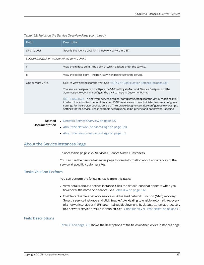
Table 162: Fields on the Service Overview Page (continued)
DescriptionField
Specify the license cost for the network service in USD.License cost
Service Configuration (graphic of the service chain)
View the ingress point—the point at which packets enter the service.I
View the egress point—the point at which packets exit the service.E
Click to view settings for the VNF. See “vSRX VNF Configuration Settings” on page 333.
The service designer can configure the VNF settings in Network Service Designer and theadministrative user can configure the VNF settings in Customer Portal.
BESTPRACTICE: The network service designer configures settings for the virtualmachine (VM)in which the virtualized network function (VNF) resides and the administrative user configuressettings for the service, such as policies. The service designer can also configure a few examplesettings for the service. These example settings should be generic and not network-specific.
One or more VNFs
RelatedDocumentation
Network Service Overview on page 327•
• About the Network Services Page on page 328
• About the Service Instances Page on page 331
About the Service Instances Page
To access this page, click Services > Service Name > Instances
You can use the Service Instances page to view information about occurrences of the
service at specific customer sites.
Tasks You Can Perform
You can perform the following tasks from this page:
• View details about a service instance. Click the details icon that appears when you
hover over the name of a service. See Table 164 on page 332.
• Enable or disable a network service or virtualized network function (VNF) recovery.
Select a service instance and click Enable Auto Healing to enable automatic recovery
ofanetwork serviceorVNF inacentralizeddeployment.Bydefault, automatic recovery
of a network service or VNFs is enabled. See “ConfiguringVNFProperties” onpage 333.
Field Descriptions
Table 163onpage 332 shows thedescriptions of the fields on theService Instances page.
331Copyright © 2018, Juniper Networks, Inc.
Chapter 31: Managing Network Services
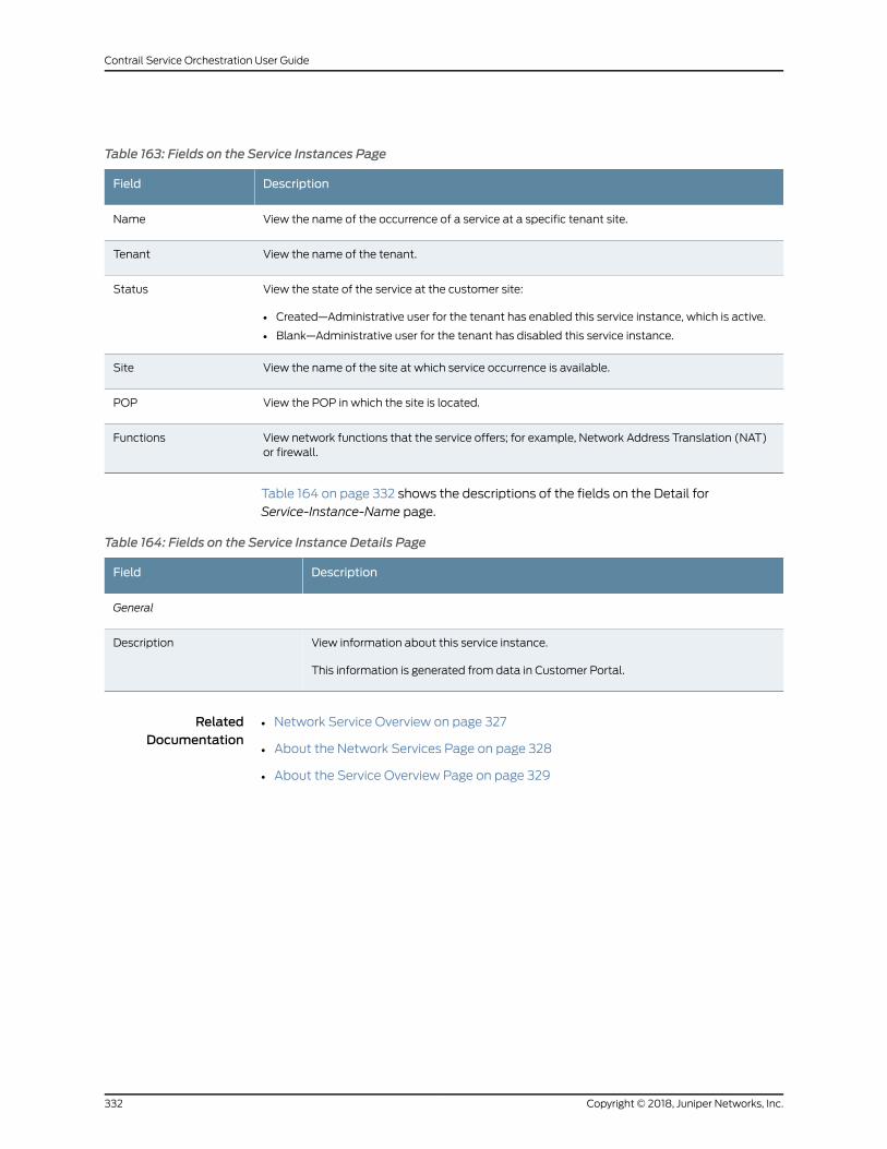
Table 163: Fields on the Service Instances Page
DescriptionField
View the name of the occurrence of a service at a specific tenant site.Name
View the name of the tenant.Tenant
View the state of the service at the customer site:
• Created—Administrative user for the tenant has enabled this service instance, which is active.
• Blank—Administrative user for the tenant has disabled this service instance.
Status
View the name of the site at which service occurrence is available.Site
View the POP in which the site is located.POP
View network functions that the service offers; for example, Network Address Translation (NAT)or firewall.
Functions
Table 164 on page 332 shows the descriptions of the fields on the Detail for
Service-Instance-Name page.
Table 164: Fields on the Service Instance Details Page
DescriptionField
General
View information about this service instance.
This information is generated from data in Customer Portal.
Description
RelatedDocumentation
Network Service Overview on page 327•
• About the Network Services Page on page 328
• About the Service Overview Page on page 329
Copyright © 2018, Juniper Networks, Inc.332
Contrail Service Orchestration User Guide
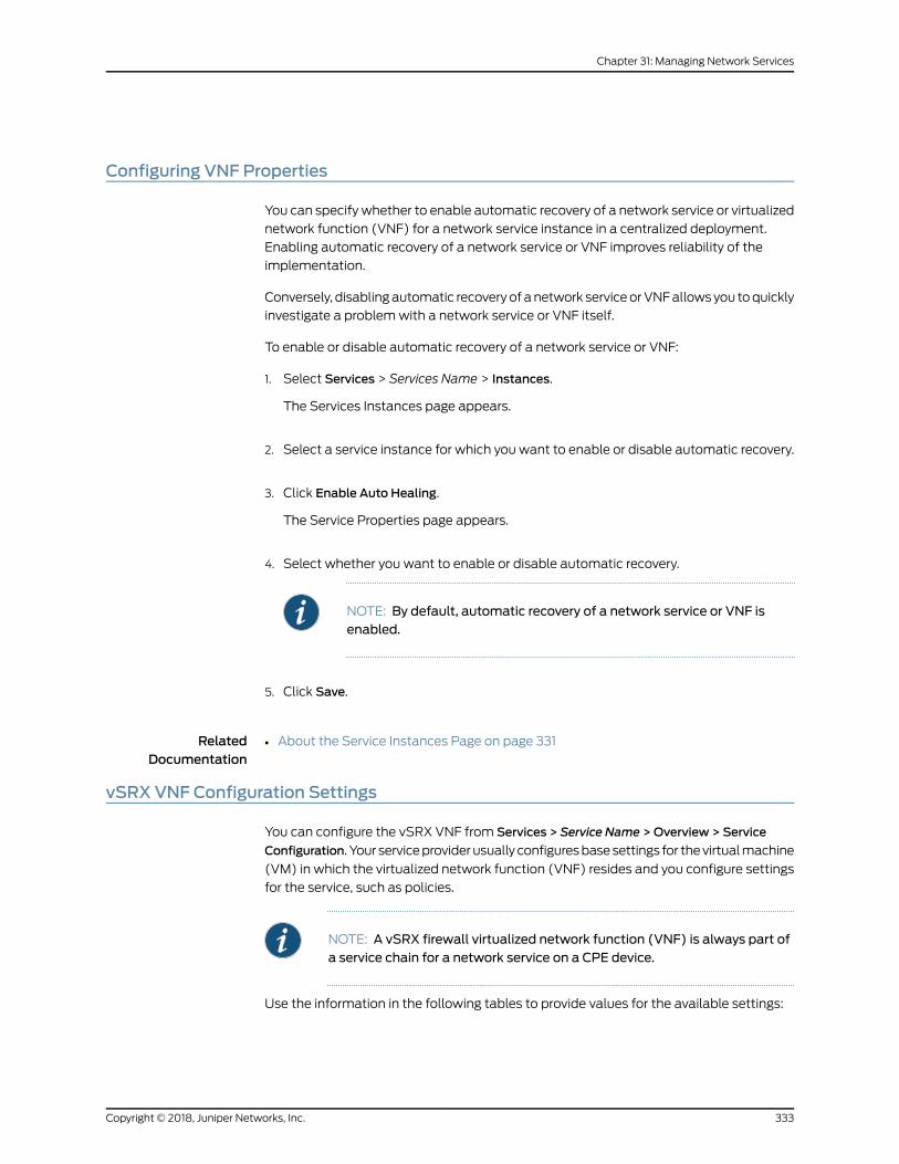
Configuring VNF Properties
You can specify whether to enable automatic recovery of a network service or virtualized
network function (VNF) for a network service instance in a centralized deployment.
Enabling automatic recovery of a network service or VNF improves reliability of the
implementation.
Conversely, disablingautomatic recoveryof anetwork serviceorVNFallowsyou toquickly
investigate a problemwith a network service or VNF itself.
To enable or disable automatic recovery of a network service or VNF:
1. Select Services > Services Name > Instances.
The Services Instances page appears.
2. Select a service instance for which you want to enable or disable automatic recovery.
3. Click Enable Auto Healing.
The Service Properties page appears.
4. Select whether you want to enable or disable automatic recovery.
NOTE: By default, automatic recovery of a network service or VNF isenabled.
5. Click Save.
RelatedDocumentation
About the Service Instances Page on page 331•
vSRX VNF Configuration Settings
You can configure the vSRX VNF from Services > Service Name >Overview > Service
Configuration. Your serviceproviderusually configuresbasesettings for thevirtualmachine
(VM) in which the virtualized network function (VNF) resides and you configure settings
for the service, such as policies.
NOTE: A vSRX firewall virtualized network function (VNF) is always part ofa service chain for a network service on a CPE device.
Use the information in the following tables to provide values for the available settings:
333Copyright © 2018, Juniper Networks, Inc.
Chapter 31: Managing Network Services
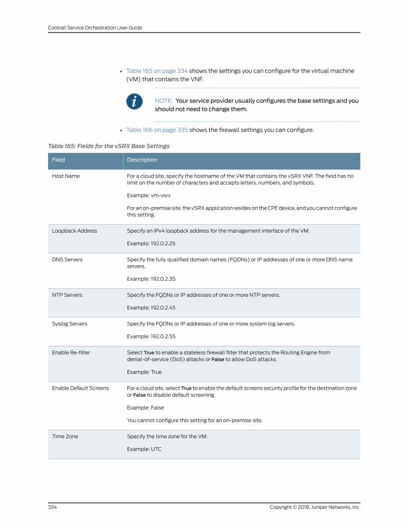
• Table 165 on page 334 shows the settings you can configure for the virtual machine
(VM) that contains the VNF.
NOTE: Your service provider usually configures the base settings and youshould not need to change them.
• Table 166 on page 335 shows the firewall settings you can configure.
Table 165: Fields for the vSRX Base Settings
DescriptionField
For a cloud site, specify the hostname of the VM that contains the vSRX VNF. The field has nolimit on the number of characters and accepts letters, numbers, and symbols.
Example: vm-vsrx
Foranon-premisesite, thevSRXapplication resideson theCPEdevice, andyoucannotconfigurethis setting.
Host Name
Specify an IPv4 loopback address for the management interface of the VM.
Example: 192.0.2.25
Loopback Address
Specify the fully qualified domain names (FQDNs) or IP addresses of one or more DNS nameservers.
Example: 192.0.2.35
DNS Servers
Specify the FQDNs or IP addresses of one or more NTP servers.
Example: 192.0.2.45
NTP Servers
Specify the FQDNs or IP addresses of one or more system log servers.
Example: 192.0.2.55
Syslog Servers
Select True to enable a stateless firewall filter that protects the Routing Engine fromdenial-of-service (DoS) attacks or False to allow DoS attacks.
Example: True
Enable Re-filter
For a cloud site, select True to enable the default screens security profile for the destination zoneor False to disable default screening.
Example: False
You cannot configure this setting for an on-premise site.
Enable Default Screens
Specify the time zone for the VM.
Example: UTC
Time Zone
Copyright © 2018, Juniper Networks, Inc.334
Contrail Service Orchestration User Guide
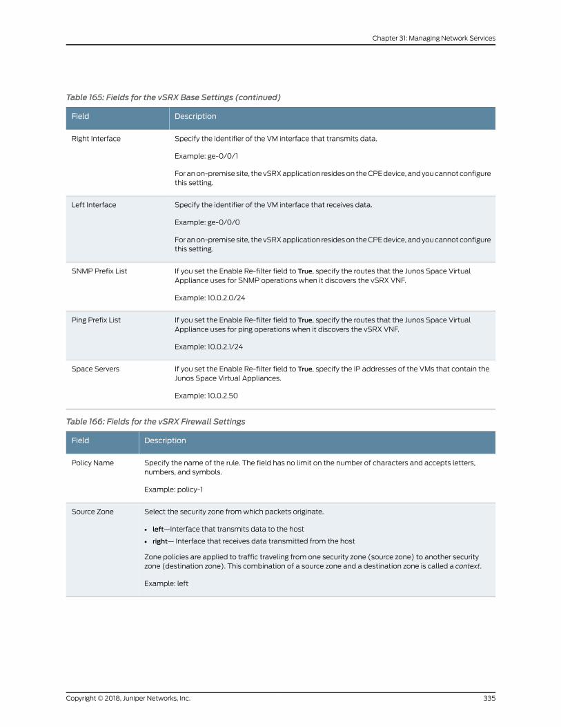
Table 165: Fields for the vSRX Base Settings (continued)
DescriptionField
Specify the identifier of the VM interface that transmits data.
Example: ge-0/0/1
Foranon-premisesite, thevSRXapplication resideson theCPEdevice, andyoucannotconfigurethis setting.
Right Interface
Specify the identifier of the VM interface that receives data.
Example: ge-0/0/0
Foranon-premisesite, thevSRXapplication resideson theCPEdevice, andyoucannotconfigurethis setting.
Left Interface
If you set the Enable Re-filter field to True, specify the routes that the Junos Space VirtualAppliance uses for SNMP operations when it discovers the vSRX VNF.
Example: 10.0.2.0/24
SNMP Prefix List
If you set the Enable Re-filter field to True, specify the routes that the Junos Space VirtualAppliance uses for ping operations when it discovers the vSRX VNF.
Example: 10.0.2.1/24
Ping Prefix List
If you set the Enable Re-filter field to True, specify the IP addresses of the VMs that contain theJunos Space Virtual Appliances.
Example: 10.0.2.50
Space Servers
Table 166: Fields for the vSRX Firewall Settings
DescriptionField
Specify the name of the rule. The field has no limit on the number of characters and accepts letters,numbers, and symbols.
Example: policy-1
Policy Name
Select the security zone fromwhich packets originate.
• left—Interface that transmits data to the host
• right— Interface that receives data transmitted from the host
Zone policies are applied to traffic traveling from one security zone (source zone) to another securityzone (destination zone). This combination of a source zone and a destination zone is called a context.
Example: left
Source Zone
335Copyright © 2018, Juniper Networks, Inc.
Chapter 31: Managing Network Services
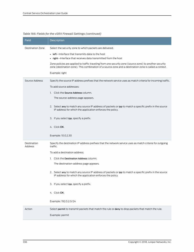
Table 166: Fields for the vSRX Firewall Settings (continued)
DescriptionField
Select the security zone to which packets are delivered.
• left—Interface that transmits data to the host
• right—Interface that receives data transmitted from the host
Zone policies are applied to traffic traveling from one security zone (source zone) to another securityzone (destination zone). This combination of a source zone and a destination zone is called a context.
Example: right
Destination Zone
Specify the source IP address prefixes that the network service uses asmatch criteria for incoming traffic.
To add source addresses:
1. Click the Source Address column.
The source-address page appears.
2. Select any to match any source IP address of packets or ipp to match a specific prefix in the sourceIP address for which the application enforces the policy.
3. If you select ipp, specify a prefix.
4. ClickOK.
Example: 10.0.2.30
Source Address
Specify the destination IP address prefixes that the network service uses as match criteria for outgoingtraffic.
To add a destination address:
1. Click the Destination Address column.
The destination-address page appears.
2. Select any to match any source IP address of packets or ipp to match a specific prefix in the sourceIP address for which the application enforces the policy.
3. If you select ipp, specify a prefix.
4. ClickOK.
Example: 192.0.2.0/24
DestinationAddress
Select permit to transmit packets that match the rule or deny to drop packets that match the rule.
Example: permit
Action
Copyright © 2018, Juniper Networks, Inc.336
Contrail Service Orchestration User Guide
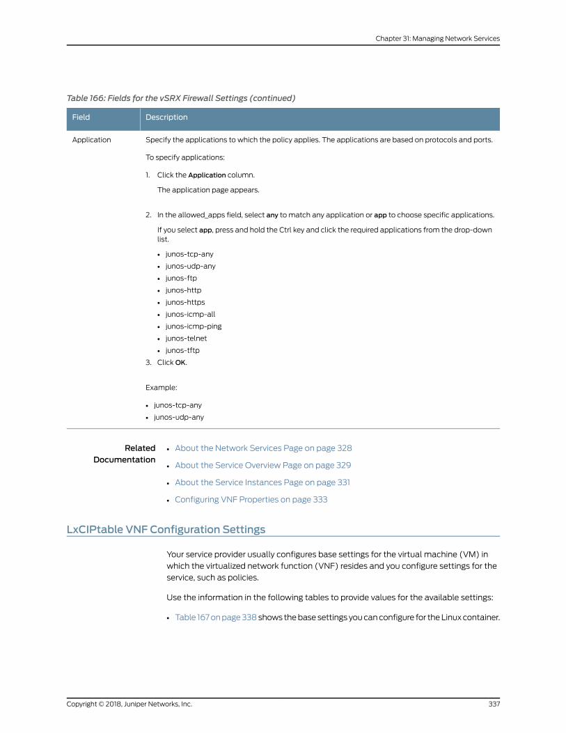
Table 166: Fields for the vSRX Firewall Settings (continued)
DescriptionField
Specify the applications to which the policy applies. The applications are based on protocols and ports.
To specify applications:
1. Click the Application column.
The application page appears.
2. In the allowed_apps field, select any to match any application or app to choose specific applications.
If you select app, press and hold the Ctrl key and click the required applications from the drop-downlist.
• junos-tcp-any
• junos-udp-any
• junos-ftp
• junos-http
• junos-https
• junos-icmp-all
• junos-icmp-ping
• junos-telnet
• junos-tftp
3. ClickOK.
Example:
• junos-tcp-any
• junos-udp-any
Application
RelatedDocumentation
About the Network Services Page on page 328•
• About the Service Overview Page on page 329
• About the Service Instances Page on page 331
• Configuring VNF Properties on page 333
LxCIPtable VNF Configuration Settings
Your service provider usually configures base settings for the virtual machine (VM) in
which the virtualized network function (VNF) resides and you configure settings for the
service, such as policies.
Use the information in the following tables to provide values for the available settings:
• Table 167onpage338shows thebasesettings youcanconfigure for theLinuxcontainer.
337Copyright © 2018, Juniper Networks, Inc.
Chapter 31: Managing Network Services
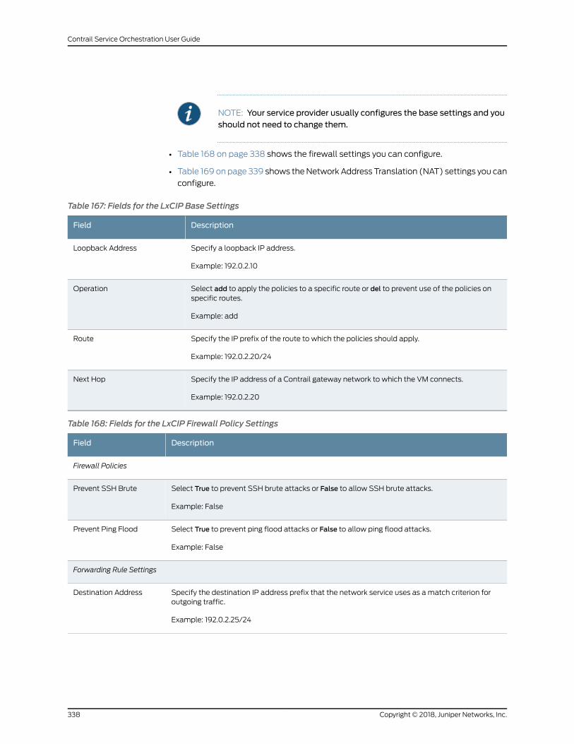
NOTE: Your service provider usually configures the base settings and youshould not need to change them.
• Table 168 on page 338 shows the firewall settings you can configure.
• Table 169 on page 339 shows theNetwork Address Translation (NAT) settings you can
configure.
Table 167: Fields for the LxCIP Base Settings
DescriptionField
Specify a loopback IP address.
Example: 192.0.2.10
Loopback Address
Select add to apply the policies to a specific route or del to prevent use of the policies onspecific routes.
Example: add
Operation
Specify the IP prefix of the route to which the policies should apply.
Example: 192.0.2.20/24
Route
Specify the IP address of a Contrail gateway network to which the VM connects.
Example: 192.0.2.20
Next Hop
Table 168: Fields for the LxCIP Firewall Policy Settings
DescriptionField
Firewall Policies
Select True to prevent SSH brute attacks or False to allow SSH brute attacks.
Example: False
Prevent SSH Brute
Select True to prevent ping flood attacks or False to allow ping flood attacks.
Example: False
Prevent Ping Flood
Forwarding Rule Settings
Specify the destination IP address prefix that the network service uses as amatch criterion foroutgoing traffic.
Example: 192.0.2.25/24
Destination Address
Copyright © 2018, Juniper Networks, Inc.338
Contrail Service Orchestration User Guide
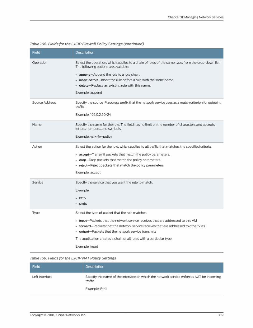
Table 168: Fields for the LxCIP Firewall Policy Settings (continued)
DescriptionField
Select the operation, which applies to a chain of rules of the same type, from the drop-down list.The following options are available:
• append—Append the rule to a rule chain.
• insert-before—Insert the rule before a rule with the same name.
• delete—Replace an existing rule with this name.
Example: append
Operation
Specify the source IP address prefix that the network service uses as amatch criterion for outgoingtraffic.
Example: 192.0.2.20/24
Source Address
Specify the name for the rule. The field has no limit on the number of characters and acceptsletters, numbers, and symbols.
Example: vsrx-fw-policy
Name
Select the action for the rule, which applies to all traffic that matches the specified criteria.
• accept—Transmit packets that match the policy parameters.
• drop—Drop packets that match the policy parameters.
• reject—Reject packets that match the policy parameters.
Example: accept
Action
Specify the service that you want the rule to match.
Example:
• http
• smtp
Service
Select the type of packet that the rule matches.
• input—Packets that the network service receives that are addressed to this VM
• forward—Packets that the network service receives that are addressed to other VMs
• output—Packets that the network service transmits
The application creates a chain of all rules with a particular type.
Example: input
Type
Table 169: Fields for the LxCIP NAT Policy Settings
DescriptionField
Specify the name of the interface on which the network service enforces NAT for incomingtraffic.
Example: Eth1
Left Interface
339Copyright © 2018, Juniper Networks, Inc.
Chapter 31: Managing Network Services
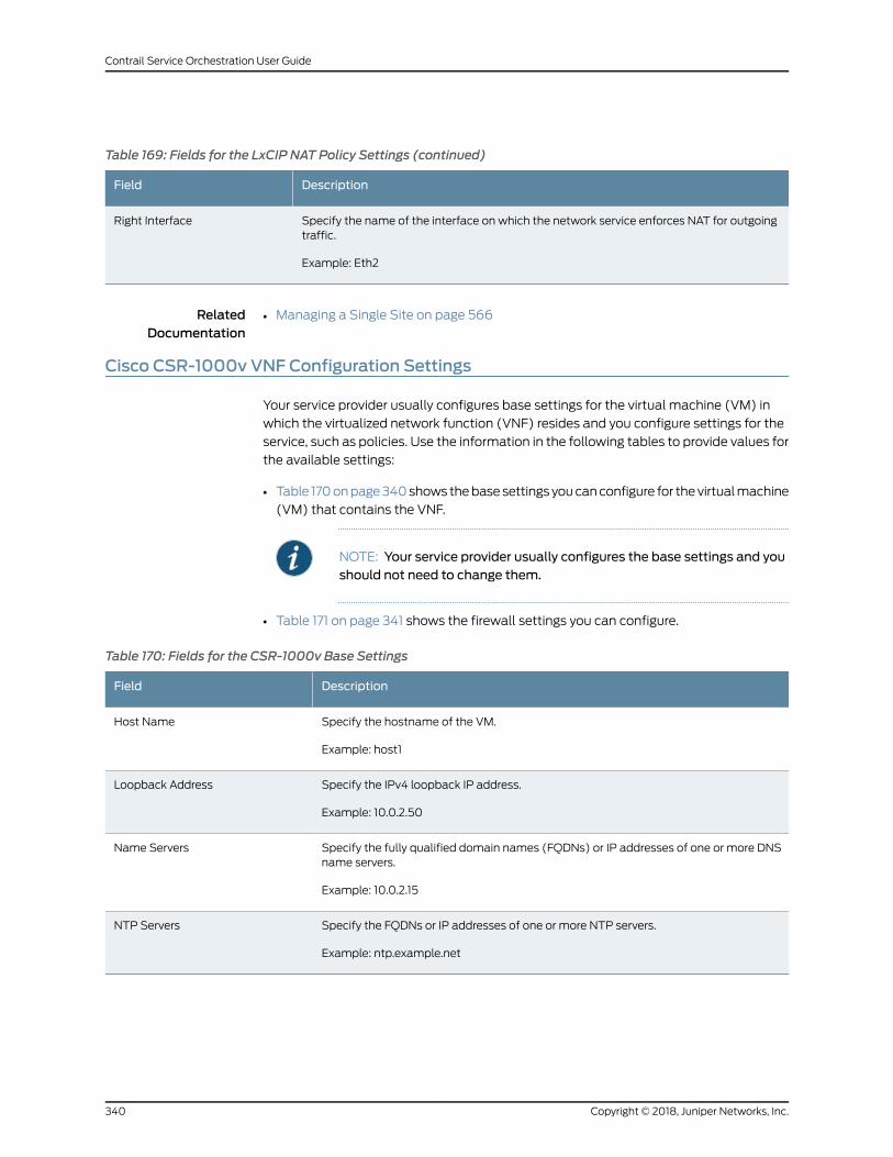
Table 169: Fields for the LxCIP NAT Policy Settings (continued)
DescriptionField
Specify the name of the interface on which the network service enforces NAT for outgoingtraffic.
Example: Eth2
Right Interface
RelatedDocumentation
Managing a Single Site on page 566•
Cisco CSR-1000v VNF Configuration Settings
Your service provider usually configures base settings for the virtual machine (VM) in
which the virtualized network function (VNF) resides and you configure settings for the
service, such as policies. Use the information in the following tables to provide values for
the available settings:
• Table 170onpage340shows thebasesettings youcanconfigure for thevirtualmachine
(VM) that contains the VNF.
NOTE: Your service provider usually configures the base settings and youshould not need to change them.
• Table 171 on page 341 shows the firewall settings you can configure.
Table 170: Fields for the CSR-1000v Base Settings
DescriptionField
Specify the hostname of the VM.
Example: host1
Host Name
Specify the IPv4 loopback IP address.
Example: 10.0.2.50
Loopback Address
Specify the fully qualified domain names (FQDNs) or IP addresses of one or more DNSname servers.
Example: 10.0.2.15
Name Servers
Specify the FQDNs or IP addresses of one or more NTP servers.
Example: ntp.example.net
NTP Servers
Copyright © 2018, Juniper Networks, Inc.340
Contrail Service Orchestration User Guide
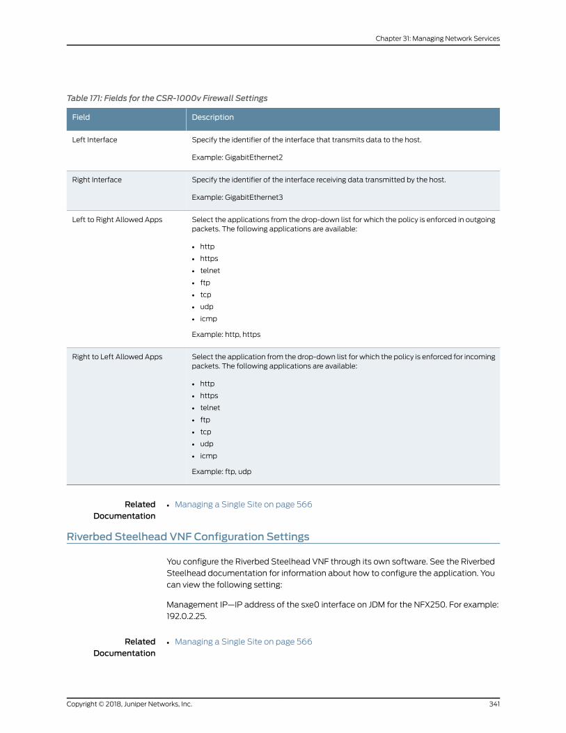
Table 171: Fields for the CSR-1000v Firewall Settings
DescriptionField
Specify the identifier of the interface that transmits data to the host.
Example: GigabitEthernet2
Left Interface
Specify the identifier of the interface receiving data transmitted by the host.
Example: GigabitEthernet3
Right Interface
Select the applications from the drop-down list for which the policy is enforced in outgoingpackets. The following applications are available:
• http
• https
• telnet
• ftp
• tcp
• udp
• icmp
Example: http, https
Left to Right Allowed Apps
Select the application from the drop-down list for which the policy is enforced for incomingpackets. The following applications are available:
• http
• https
• telnet
• ftp
• tcp
• udp
• icmp
Example: ftp, udp
Right to Left Allowed Apps
RelatedDocumentation
Managing a Single Site on page 566•
Riverbed Steelhead VNF Configuration Settings
You configure the Riverbed Steelhead VNF through its own software. See the Riverbed
Steelhead documentation for information about how to configure the application. You
can view the following setting:
Management IP—IP address of the sxe0 interface on JDM for the NFX250. For example:
192.0.2.25.
RelatedDocumentation
• Managing a Single Site on page 566
341Copyright © 2018, Juniper Networks, Inc.
Chapter 31: Managing Network Services

Copyright © 2018, Juniper Networks, Inc.342
Contrail Service Orchestration User Guide
CHAPTER 32
Managing Firewall Policies
• Firewall Policy Overview on page 343
• About the Firewall Policy Page on page 344
• Creating Firewall Policy Intents on page 345
• Editing, Cloning, and Deleting Firewall Policy Intents on page 351
• Selecting Firewall Source on page 353
• Selecting Firewall Destination on page 356
• Firewall Policy Examples on page 359
• Firewall Policy Schedules Overview on page 389
• About the Firewall Policy Schedules Page on page 389
• Creating Schedules on page 390
• Editing, Cloning, and Deleting Schedules on page 392
Firewall Policy Overview
Contrail Service Orchestration (CSO) provides the ability to create, modify, and delete
firewall policy intents associated with a firewall policy. Firewall policies are presented
as intent-based policies. A firewall policy intent controls transit traffic within a context
that is derived out of the end-points defined in the intent. Intent-based firewall policies
can incorporate both transport layer (Layer 4) and application layer (Layer 7) firewall
constructs in a single intent. The underlying system, automatically analyzes the intent,
translates them into the set of rules the devices understand. The choice of sequence and
the assignment happens implicitly based on the endpoints in the intent definition. The
intent consist of source anddestination endpoints. Endpoints could beapplications (L7),
sites or site groups, IP address/address-groups, services, or departments.
NOTE: Intentbasedpoliciesarenotapplicable forHybridWANdeployments.
Firewall policies provide security functionality by enforcing intents on traffic that passes
throughadevice. Traffic is permittedor deniedbasedon theactiondefinedas the firewall
policy intent.
343Copyright © 2018, Juniper Networks, Inc.
A firewall policy provides the following features:
• Permits, rejects, or denies traffic based on the application in use.
• Identifies not only HTTP but also any application running on top of it, enabling you to
properly enforce policies. For example, an application firewall intent could block HTTP
traffic from Facebook but allowWeb access to HTTP traffic fromMicrosoft Outlook.
• Provides the ability to perform threat management on permitted traffic using UTM
profiles. For more information on UTM profiles, see “UTMOverview” on page 396.
RelatedDocumentation
About the Firewall Policy Page on page 344•
• Firewall Policy Examples on page 359
• Creating Firewall Policy Intents on page 345
• Editing, Cloning, and Deleting Firewall Policy Intents on page 351
About the Firewall Policy Page
To access this page, select Configuration > Firewall > Firewall Policy.
Use this page to view andmanage policy intents associatedwith your site or site groups.
You can filter and sort this information to get a better understanding of what you want
to configure.
Tasks You Can Perform
You can perform the following tasks from this page:
• Create a firewall policy intent. See “Creating Firewall Policy Intents” on page 345.
• Modify, cloneordelete firewall policy intents. See “Editing,Cloning, andDeletingFirewall
Policy Intents” on page 351.
• Deploy a firewall policy. See “Deploying Policies” on page 532.
NOTE: An orange line is displayed against all undeployed firewall policyintents.
• Search for a firewall policy intent. See “Searching for Text in an Object Data Table” on
page 242.
• Show or hide columns. Click the ShowHide Columns icon at the top right corner of the
page.
• View undeployed intents. Click the ShowHide Columns icon at the top right corner of
the page and select Undeployed Intent underQuick Filters.
Field Descriptions
Table 172 on page 345 provides guidelines on using the fields on the Firewall Policy page.
Copyright © 2018, Juniper Networks, Inc.344
Contrail Service Orchestration User Guide
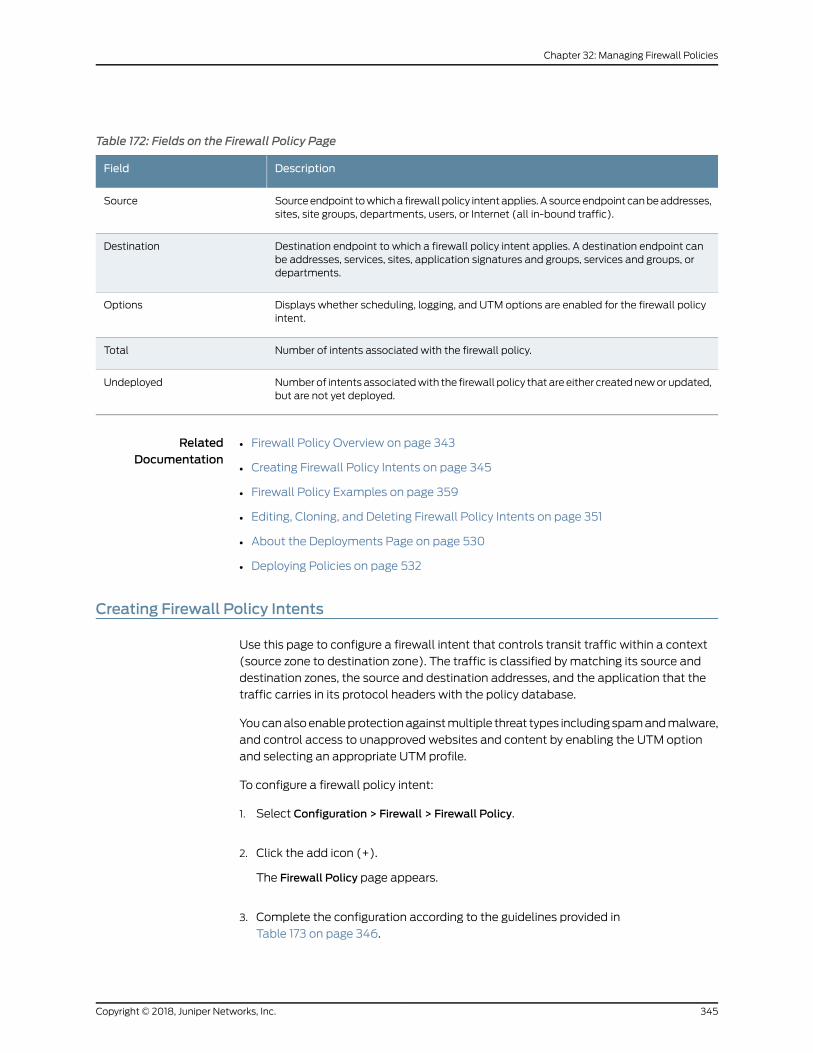
Table 172: Fields on the Firewall Policy Page
DescriptionField
Sourceendpoint towhicha firewall policy intentapplies.Asourceendpoint canbeaddresses,sites, site groups, departments, users, or Internet (all in-bound traffic).
Source
Destination endpoint to which a firewall policy intent applies. A destination endpoint canbe addresses, services, sites, application signatures and groups, services and groups, ordepartments.
Destination
Displays whether scheduling, logging, and UTM options are enabled for the firewall policyintent.
Options
Number of intents associated with the firewall policy.Total
Numberof intents associatedwith the firewall policy that are either createdneworupdated,but are not yet deployed.
Undeployed
RelatedDocumentation
Firewall Policy Overview on page 343•
• Creating Firewall Policy Intents on page 345
• Firewall Policy Examples on page 359
• Editing, Cloning, and Deleting Firewall Policy Intents on page 351
• About the Deployments Page on page 530
• Deploying Policies on page 532
Creating Firewall Policy Intents
Use this page to configure a firewall intent that controls transit traffic within a context
(source zone to destination zone). The traffic is classified by matching its source and
destination zones, the source and destination addresses, and the application that the
traffic carries in its protocol headers with the policy database.
Youcanalsoenableprotectionagainstmultiple threat types includingspamandmalware,
and control access to unapproved websites and content by enabling the UTM option
and selecting an appropriate UTM profile.
To configure a firewall policy intent:
1. Select Configuration > Firewall > Firewall Policy.
2. Click the add icon (+).
The Firewall Policy page appears.
3. Complete the configuration according to the guidelines provided in
Table 173 on page 346.
345Copyright © 2018, Juniper Networks, Inc.
Chapter 32: Managing Firewall Policies
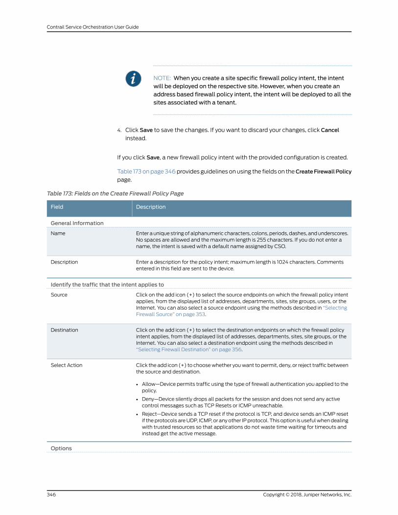
NOTE: When you create a site specific firewall policy intent, the intentwill be deployed on the respective site. However, when you create anaddress based firewall policy intent, the intent will be deployed to all thesites associated with a tenant.
4. Click Save to save the changes. If you want to discard your changes, click Cancel
instead.
If you click Save, a new firewall policy intent with the provided configuration is created.
Table 173 onpage346provides guidelines onusing the fields on theCreateFirewallPolicy
page.
Table 173: Fields on the Create Firewall Policy Page
DescriptionField
General Information
Enter aunique stringof alphanumeric characters, colons, periods, dashes, andunderscores.No spaces are allowed and themaximum length is 255 characters. If you do not enter aname, the intent is saved with a default name assigned by CSO.
Name
Enter a description for the policy intent; maximum length is 1024 characters. Commentsentered in this field are sent to the device.
Description
Identify the traffic that the intent applies to
Click on the add icon (+) to select the source endpoints on which the firewall policy intentapplies, from the displayed list of addresses, departments, sites, site groups, users, or theInternet. You can also select a source endpoint using the methods described in “SelectingFirewall Source” on page 353.
Source
Click on the add icon (+) to select the destination endpoints on which the firewall policyintent applies, from the displayed list of addresses, departments, sites, site groups, or theInternet. You can also select a destination endpoint using the methods described in“Selecting Firewall Destination” on page 356.
Destination
Click the add icon (+) to choosewhether youwant to permit, deny, or reject traffic betweenthe source and destination.
• Allow—Device permits traffic using the type of firewall authentication you applied to thepolicy.
• Deny—Device silently drops all packets for the session and does not send any activecontrol messages such as TCP Resets or ICMP unreachable.
• Reject—Device sends a TCP reset if the protocol is TCP, and device sends an ICMP resetif theprotocols areUDP, ICMP, or anyother IPprotocol. This option is usefulwhendealingwith trusted resources so that applications do not waste time waiting for timeouts andinstead get the active message.
Select Action
Options
Copyright © 2018, Juniper Networks, Inc.346
Contrail Service Orchestration User Guide
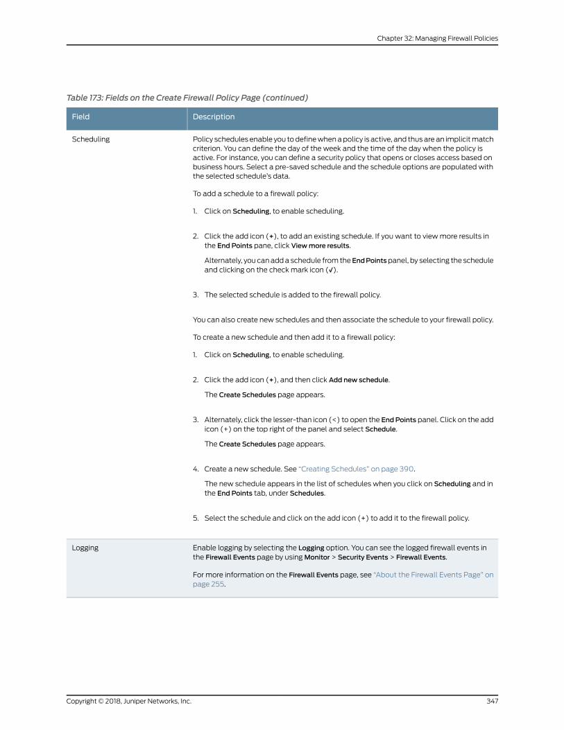
Table 173: Fields on the Create Firewall Policy Page (continued)
DescriptionField
Policy schedules enable you todefinewhenapolicy is active, and thusarean implicitmatchcriterion. You can define the day of the week and the time of the day when the policy isactive. For instance, you can define a security policy that opens or closes access based onbusiness hours. Select a pre-saved schedule and the schedule options are populated withthe selected schedule’s data.
To add a schedule to a firewall policy:
1. Click on Scheduling, to enable scheduling.
2. Click the add icon (+), to add an existing schedule. If you want to viewmore results inthe End Points pane, click Viewmore results.
Alternately, you canadda schedule from theEndPointspanel, by selecting the scheduleand clicking on the check mark icon (√).
3. The selected schedule is added to the firewall policy.
You can also create new schedules and then associate the schedule to your firewall policy.
To create a new schedule and then add it to a firewall policy:
1. Click on Scheduling, to enable scheduling.
2. Click the add icon (+), and then click Add new schedule.
The Create Schedules page appears.
3. Alternately, click the lesser-than icon (<) to open the EndPoints panel. Click on the addicon (+) on the top right of the panel and select Schedule.
The Create Schedules page appears.
4. Create a new schedule. See “Creating Schedules” on page 390.
The new schedule appears in the list of schedules when you click on Scheduling and inthe End Points tab, under Schedules.
5. Select the schedule and click on the add icon (+) to add it to the firewall policy.
Scheduling
Enable logging by selecting the Logging option. You can see the logged firewall events inthe Firewall Events page by usingMonitor > Security Events > Firewall Events.
For more information on the Firewall Events page, see “About the Firewall Events Page” onpage 255.
Logging
347Copyright © 2018, Juniper Networks, Inc.
Chapter 32: Managing Firewall Policies
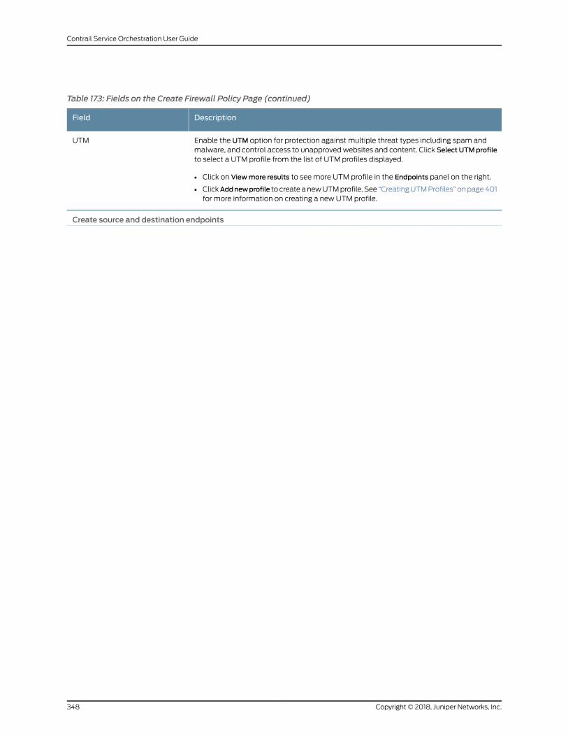
Table 173: Fields on the Create Firewall Policy Page (continued)
DescriptionField
Enable the UTM option for protection against multiple threat types including spam andmalware, and control access to unapprovedwebsites and content. Click Select UTMprofileto select a UTM profile from the list of UTM profiles displayed.
• Click on Viewmore results to seemore UTM profile in the Endpoints panel on the right.
• ClickAddnewprofile to createanewUTMprofile. See “CreatingUTMProfiles” onpage401for more information on creating a new UTM profile.
UTM
Create source and destination endpoints
Copyright © 2018, Juniper Networks, Inc.348
Contrail Service Orchestration User Guide
Table 173: Fields on the Create Firewall Policy Page (continued)
DescriptionField
End Points
349Copyright © 2018, Juniper Networks, Inc.
Chapter 32: Managing Firewall Policies
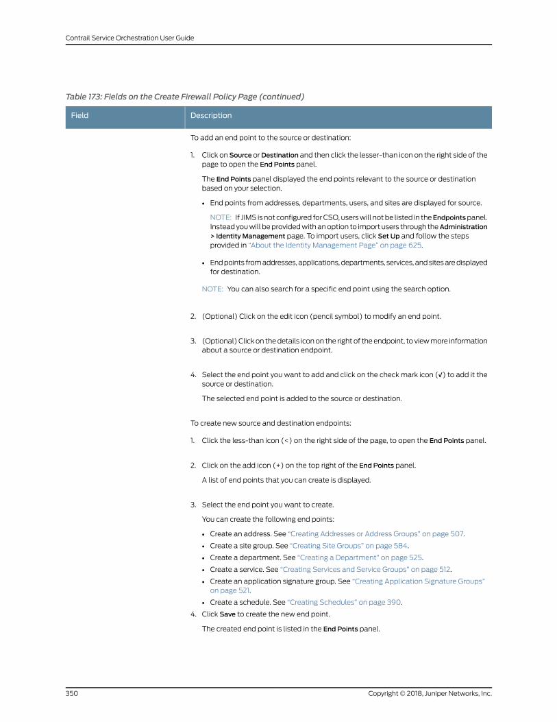
Table 173: Fields on the Create Firewall Policy Page (continued)
DescriptionField
To add an end point to the source or destination:
1. Click onSource orDestination and then click the lesser-than icon on the right side of thepage to open the End Points panel.
The End Points panel displayed the end points relevant to the source or destinationbased on your selection.
• End points from addresses, departments, users, and sites are displayed for source.
NOTE: If JIMS isnot configured forCSO,userswill notbe listed in theEndpointspanel.Insteadyouwill beprovidedwithanoption to import users through theAdministration> Identity Management page. To import users, click Set Up and follow the stepsprovided in “About the Identity Management Page” on page 625.
• Endpoints fromaddresses,applications,departments, services, andsitesaredisplayedfor destination.
NOTE: You can also search for a specific end point using the search option.
2. (Optional) Click on the edit icon (pencil symbol) to modify an end point.
3. (Optional)Clickon thedetails iconon the rightof theendpoint, to viewmore informationabout a source or destination endpoint.
4. Select the end point you want to add and click on the checkmark icon (√) to add it thesource or destination.
The selected end point is added to the source or destination.
To create new source and destination endpoints:
1. Click the less-than icon (<) on the right side of the page, to open the End Points panel.
2. Click on the add icon (+) on the top right of the End Points panel.
A list of end points that you can create is displayed.
3. Select the end point you want to create.
You can create the following end points:
• Create an address. See “Creating Addresses or Address Groups” on page 507.
• Create a site group. See “Creating Site Groups” on page 584.
• Create a department. See “Creating a Department” on page 525.
• Create a service. See “Creating Services and Service Groups” on page 512.
• Create an application signature group. See “Creating Application Signature Groups”on page 521.
• Create a schedule. See “Creating Schedules” on page 390.
4. Click Save to create the new end point.
The created end point is listed in the End Points panel.
Copyright © 2018, Juniper Networks, Inc.350
Contrail Service Orchestration User Guide

Table 173: Fields on the Create Firewall Policy Page (continued)
DescriptionField
Select the endpoint youwant to add to the source or destination, and click on the checkmark icon (√).
5.
The end point is added to the source or destination.
RelatedDocumentation
Firewall Policy Overview on page 343•
• About the Firewall Policy Page on page 344
• Firewall Policy Examples on page 359
• Editing, Cloning, and Deleting Firewall Policy Intents on page 351
• Creating Addresses or Address Groups on page 507
• Creating Site Groups on page 584
• About the Sites Page on page 535
• Creating a Department on page 525
• Creating Application Signature Groups on page 521
• Creating Services and Service Groups on page 512
Editing, Cloning, and Deleting Firewall Policy Intents
You can edit, clone, and delete firewall policy intents from the Firewall Policy page.
• Editing Firewall Policy Intents on page 351
• Cloning Firewall Policy Intents on page 352
• Deleting Firewall Policy Intents on page 352
Editing Firewall Policy Intents
Tomodify the parameters configured for a firewall policy intent:
1. Select Configuration > Firewall > Firewall Policy.
The Firewall Policy page appears, displaying the intents associated with the policy.
2. Hover over the firewall policy intent that you want to edit, and then click on the edit
icon (pencil symbol) that appears on the right side of the intent.
The Firewall Policy page displays the same options as those that appear when you
create a new firewall policy intent.
351Copyright © 2018, Juniper Networks, Inc.
Chapter 32: Managing Firewall Policies
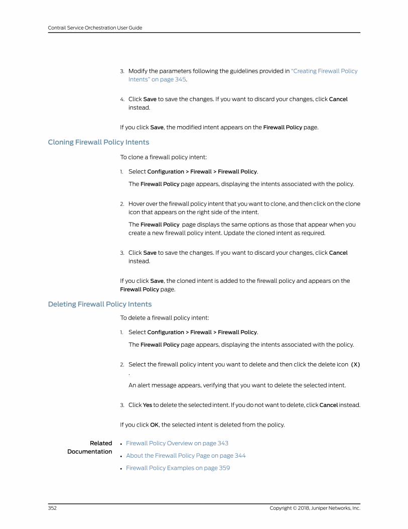
3. Modify the parameters following the guidelines provided in “Creating Firewall Policy
Intents” on page 345.
4. Click Save to save the changes. If you want to discard your changes, click Cancel
instead.
If you click Save, the modified intent appears on the Firewall Policy page.
Cloning Firewall Policy Intents
To clone a firewall policy intent:
1. Select Configuration > Firewall > Firewall Policy.
The Firewall Policy page appears, displaying the intents associated with the policy.
2. Hover over the firewall policy intent that youwant to clone, and then click on the clone
icon that appears on the right side of the intent.
The Firewall Policy page displays the same options as those that appear when you
create a new firewall policy intent. Update the cloned intent as required.
3. Click Save to save the changes. If you want to discard your changes, click Cancel
instead.
If you click Save, the cloned intent is added to the firewall policy and appears on the
Firewall Policy page.
Deleting Firewall Policy Intents
To delete a firewall policy intent:
1. Select Configuration > Firewall > Firewall Policy.
The Firewall Policy page appears, displaying the intents associated with the policy.
2. Select the firewall policy intent you want to delete and then click the delete icon (X)
.
An alert message appears, verifying that you want to delete the selected intent.
3. ClickYes todelete the selected intent. If youdonotwant todelete, clickCancel instead.
If you clickOK, the selected intent is deleted from the policy.
RelatedDocumentation
Firewall Policy Overview on page 343•
• About the Firewall Policy Page on page 344
• Firewall Policy Examples on page 359
Copyright © 2018, Juniper Networks, Inc.352
Contrail Service Orchestration User Guide
• Creating Firewall Policy Intents on page 345
Selecting Firewall Source
The followingproceduresprovides variousmethodsusingwhich youcanchoseaFirewall
source end point:
• Adding an End Point as Firewall Source on page 353
• Selecting Firewall Source Using Abbreviations on page 354
• Selecting a Firewall Source from the End Points Panel on page 354
• Creating and Selecting a Firewall Source from the End Points Panel on page 355
• Creating Addresses from Source on page 355
• Creating Departments from Source on page 355
Adding an End Point as Firewall Source
View and select the source end point from the complete list of addresses, sites, site
groups, or departments. You can also select the Internet option which denotes all
in-coming traffic from outside your network.
NOTE: When you selectAny address as a source, it implies traffic originating
within the network.
NOTE:
The followingconditionsapplywhenyouselect Internetasasourceendpoint:
• When Internet is not chosen as a source end point, it is implied that the
traffic is originating within the network.
• If you chose Internet as a source, you cannot add other sites, site groups or
departments as a source end point along with Internet.
• If you chose Internet as a source, the destination end point must be a site,
site group, or department.
1. Click the Source field. A list of relevant endpoints are displayed.
2. Click on Viewmore results link provided at the bottom of the source end points. The
complete list of addresses, departments, users, sites, and site groups is displayed in
the End Points panel on the right.
353Copyright © 2018, Juniper Networks, Inc.
Chapter 32: Managing Firewall Policies
3. (Optional) Click the edit icon to edit the address, users, department, or site group end
point. You cannot edit a site end point.
4. Click check mark icon (√) to select the end point as a source.
Selecting Firewall Source Using Abbreviations
Enter an abbreviation in the Source field to select the source end point from a filtered list
of source endpoints.
• To view a filtered list of addresses, enter ADDR or addr.
• To view a filtered list of departments, enter DEPT or dept.
• To view a filtered list of sites, enter SITE or site.
• To view a filtered list of site groups, enter STGP or stgp.
• To view a filtered list of user ids, enterUSER or user.
Click the endpoints in the filtered list to select them. You can also select the end point
from the complete list of addresses, departments, users, sites, and site groups. See
“Adding an End Point as Firewall Source” on page 353.
Selecting a Firewall Source from the End Points Panel
You can select a firewall source end point from the End Points panel. Alternately, you
can create a new firewall source end point from the End Points panel, see “Creating and
Selecting a Firewall Source from the End Points Panel” on page 355
To select an firewall source end point from the from the End Points panel:
1. Click on the Source field.
2. Click the lesser-than icon (<) on the right.
TheEndPointspanel appears, displaying the list of available addresses, departments,
users, sites, and site groups.
3. (Optional) To viewmore information about a source end point, click the details icon
on the right of the end point. To edit the source end point, click the edit icon (pencil
symbol) on the right of the end point.
NOTE: You can only edit or view details of a source end point if theseoptions appear on right side of the end point when you hover over it. Notall endpoints provide these options.
4. Click the check mark icon (√) to add the end point as a source.
Copyright © 2018, Juniper Networks, Inc.354
Contrail Service Orchestration User Guide
Creating and Selecting a Firewall Source from the End Points Panel
To create an new source end point from the End Points panel:
1. Click the add icon (+) on the top right of the panel and select the type of end point
you want to create, among the options provided.
Basedon theoption you select, the respectivepageappears. Fill in the requireddetails
to create a new end point.
• To create a new address, see “Creating Addresses or Address Groups” on page 507.
• To create a new department, see “Creating a Department” on page 525.
• To create a site or site group department, see “Creating Site Groups” on page 584.
After the end point is created, it appears in the End Points panel.
2. Click the check mark icon (√) to add the new end point as a source.
Creating Addresses from Source
You can use one of the followingways to create a new address from the Source field and
use the newly created address as a source end point:
• Type the address directly in the Source field. If the address is valid, it is created
immediately and added as a source end point.
• Create an address from the Source field, using the following steps:
1. In the Source field, type addr. The Add new address link appears at the bottom of
the list of addresses.
2. Click Add new address to create a new address.
The Create Addresses page appears.
3. Configure thenewaddress.See “CreatingAddressesorAddressGroups”onpage507.
4. Click Save to save the new address.
The new address is created, and will be listed as an option for the source. Select
the new address to add it to the source.
Creating Departments from Source
Create a new department from the Source field and use the newly created department
as a source end point:
355Copyright © 2018, Juniper Networks, Inc.
Chapter 32: Managing Firewall Policies
To create a new department from Source:
1. In Source, type dept. The link Add new department appears at the bottom of the list
of departments.
2. Click on Add new department, to create a new department.
The Create Department page appears.
3. Configure the new department. See “Creating a Department” on page 525.
4. Click Save to save the new department.
The new department is created, and will be listed as an option for the source. Select
the new department to add it to the source.
RelatedDocumentation
Selecting Firewall Destination on page 356•
• Creating Firewall Policy Intents on page 345
• Firewall Policy Overview on page 343
• About the Firewall Policy Page on page 344
• Editing, Cloning, and Deleting Firewall Policy Intents on page 351
Selecting Firewall Destination
The following procedures provides variousmethods usingwhich you can chose a firewall
destination end point:
• Adding an End Point as Firewall Destination on page 357
• Selecting Firewall Destination Using Abbreviations on page 357
• Selecting a Firewall Destination from the End Points Panel on page 357
• Creating and Selecting a Firewall Destination from the End Points Panel on page 358
• Creating Addresses from Destination on page 358
• Creating Departments from Destination on page 359
Copyright © 2018, Juniper Networks, Inc.356
Contrail Service Orchestration User Guide
Adding an End Point as Firewall Destination
View and select the end point from the complete list of addresses, applications,
departments, services, sites, or site groups.
NOTE:
• When you choose Any address or service as the destination, it implies that
traffic is flowing outside the network unless a site or department ismentioned explicitly.
• Unless you choose a site, site group, or department as a destination endpoint, it is implied the traffic will flow outside your network.
1. Click on Destination. A list of relevant end points are displayed.
2. Click on Viewmore results link provided at the bottom of the destination end points.
The complete list of addresses, departments, sites, and site groups is displayed in the
End Points panel on the right.
3. (Optional) Click the edit icon to edit the address, department, or site group end point.
You cannot edit a site end point.
4. Click check mark icon (√) to select the end point as a destination.
Selecting Firewall Destination Using Abbreviations
Enter an abbreviation in the Destination field to select the destination end point from a
filtered list of destination endpoints.
• To view a filtered list of addresses, enter ADDR or addr.
• To view a filtered list of addresses, enter APPS or apps.
• To view a filtered list of departments, enter DEPT or dept.
• To view a filtered list of services, enter SVCS or svcs.
• To view a filtered list of sites, enter SITE or site.
• To view a filtered list of site groups, enter STGP or stgp.
Click the endpoints in the filtered list to select them. You can also select the end point
from the complete list of addresses, departments, sites, and site groups. See “Adding an
End Point as Firewall Destination” on page 357.
Selecting a Firewall Destination from the End Points Panel
You can select a firewall destination end point from the End Points panel. Alternately,
you can create a new firewall destination end point from the End Points panel, see
“Creating and Selecting a Firewall Destination from the End Points Panel” on page 358.
357Copyright © 2018, Juniper Networks, Inc.
Chapter 32: Managing Firewall Policies
To select an firewall destination end point from the from the End Points panel:
1. Click on the Destination field.
2. Click the lesser-than icon (<) on the right.
TheEndPointspanel appears, displaying the list of available addresses, departments,
sites, and site groups.
3. (Optional) To viewmore information about a destination end point, click the details
icon on the right of the end point. To edit the destination end point, click the edit icon
(pencil symbol) on the right of the end point.
NOTE: You can only edit or viewdetails of a destination end point if theseoptions appear on right side of the end point when you hover over it. Notall endpoints provide these options.
4. Click the check mark icon (√) to add the end point as a destination.
Creating and Selecting a Firewall Destination from the End Points Panel
To create an new destination end point from the End Points panel:
1. Click the add icon (+) on the top right of the panel and select the type of end point
you want to create, among the options provided.
Basedon theoption you select, the respectivepageappears. Fill in the requireddetails
to create a new end point.
• To create a new address, see “Creating Addresses or Address Groups” on page 507.
• To create a new department, see “Creating a Department” on page 525.
• To create a site or site group department, see “Creating Site Groups” on page 584.
After the end point is created, it appears in the Endpoints panel.
2. Click the check mark icon (√) to add the new end point as a destination.
Creating Addresses fromDestination
You can use one of the following ways to create a new address from the Destination and
use the newly created address as a destination end point:
• Type the address directly in the Destination field. If the address is valid, it is created
immediately and added as a destination end point.
Copyright © 2018, Juniper Networks, Inc.358
Contrail Service Orchestration User Guide
• Create an address from the Destination field, using the following steps:
1. In the Destination field, type addr. The Add new address link appears at the bottom
of the list of addresses.
2. Click Add new address to create a new address.
The Create Addresses page appears.
3. Configure thenewaddress.See “CreatingAddressesorAddressGroups”onpage507.
4. Click Save to save the new address.
Thenewaddress is created, andwill be listedasanoption for thedestination. Select
the new address to add it to the destination.
Creating Departments fromDestination
Createanewdepartment fromtheDestination fieldanduse thenewlycreateddepartment
as a destination end point:
To create a new department from Destination:
1. In Destination, type dept. The link Add new department appears at the bottom of the
list of departments.
2. Click on Add new department, to create a new department.
The Create Department page appears.
3. Configure the new department. See “Creating a Department” on page 525.
4. Click Save to save the new department.
The new department is created, and will be listed as an option for the destination.
Select the new department to add it to the destination.
RelatedDocumentation
Creating Firewall Policy Intents on page 345•
• Firewall Policy Overview on page 343
• About the Firewall Policy Page on page 344
• Editing, Cloning, and Deleting Firewall Policy Intents on page 351
Firewall Policy Examples
This topic provides information on how firewall policy intents that you define as part of
your firewall policy is handled by Contrail Service Orchestration (CSO), using various
359Copyright © 2018, Juniper Networks, Inc.
Chapter 32: Managing Firewall Policies
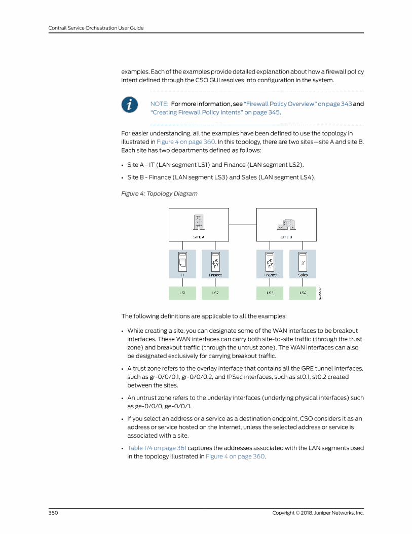
examples. Eachof theexamplesprovidedetailedexplanationabout howa firewall policy
intent defined through the CSO GUI resolves into configuration in the system.
NOTE: Formore information, see “FirewallPolicyOverview”onpage343and“Creating Firewall Policy Intents” on page 345.
For easier understanding, all the examples have been defined to use the topology in
illustrated in Figure 4 on page 360. In this topology, there are two sites—site A and site B.
Each site has two departments defined as follows:
• Site A - IT (LAN segment LS1) and Finance (LAN segment LS2).
• Site B - Finance (LAN segment LS3) and Sales (LAN segment LS4).
Figure 4: Topology Diagram
The following definitions are applicable to all the examples:
• While creating a site, you can designate some of theWAN interfaces to be breakout
interfaces. TheseWAN interfaces can carry both site-to-site traffic (through the trust
zone) and breakout traffic (through the untrust zone). TheWAN interfaces can also
be designated exclusively for carrying breakout traffic.
• A trust zone refers to the overlay interface that contains all the GRE tunnel interfaces,
such as gr-0/0/0.1, gr-0/0/0.2, and IPSec interfaces, such as st0.1, st0.2 created
between the sites.
• An untrust zone refers to the underlay interfaces (underlying physical interfaces) such
as ge-0/0/0, ge-0/0/1.
• If you select an address or a service as a destination endpoint, CSO considers it as an
address or service hosted on the Internet, unless the selected address or service is
associated with a site.
• Table 174 on page 361 captures the addresses associatedwith the LAN segments used
in the topology illustrated in Figure 4 on page 360.
Copyright © 2018, Juniper Networks, Inc.360
Contrail Service Orchestration User Guide
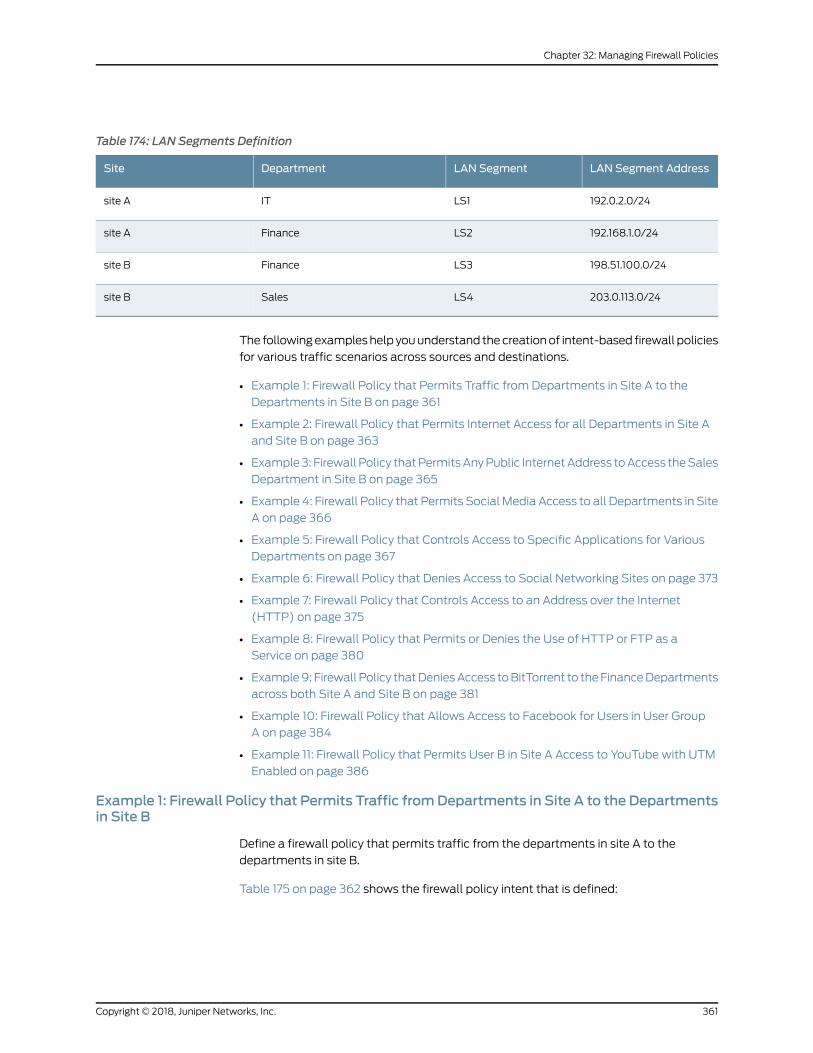
Table 174: LAN Segments Definition
LAN Segment AddressLAN SegmentDepartmentSite
192.0.2.0/24LS1ITsite A
192.168.1.0/24LS2Financesite A
198.51.100.0/24LS3Financesite B
203.0.113.0/24LS4Salessite B
The followingexampleshelp youunderstand thecreationof intent-based firewall policies
for various traffic scenarios across sources and destinations.
• Example 1: Firewall Policy that Permits Traffic from Departments in Site A to the
Departments in Site B on page 361
• Example 2: Firewall Policy that Permits Internet Access for all Departments in Site A
and Site B on page 363
• Example3: Firewall Policy thatPermitsAnyPublic InternetAddress toAccess theSales
Department in Site B on page 365
• Example 4: Firewall Policy that Permits Social Media Access to all Departments in Site
A on page 366
• Example 5: Firewall Policy that Controls Access to Specific Applications for Various
Departments on page 367
• Example 6: Firewall Policy that Denies Access to Social Networking Sites on page 373
• Example 7: Firewall Policy that Controls Access to an Address over the Internet
(HTTP) on page 375
• Example 8: Firewall Policy that Permits or Denies the Use of HTTP or FTP as a
Service on page 380
• Example9: Firewall Policy thatDeniesAccess toBitTorrent to theFinanceDepartments
across both Site A and Site B on page 381
• Example 10: Firewall Policy that Allows Access to Facebook for Users in User Group
A on page 384
• Example 11: Firewall Policy that Permits User B in Site A Access to YouTube with UTM
Enabled on page 386
Example 1: Firewall Policy that Permits Traffic fromDepartments in Site A to the Departmentsin Site B
Define a firewall policy that permits traffic from the departments in site A to the
departments in site B.
Table 175 on page 362 shows the firewall policy intent that is defined:
361Copyright © 2018, Juniper Networks, Inc.
Chapter 32: Managing Firewall Policies
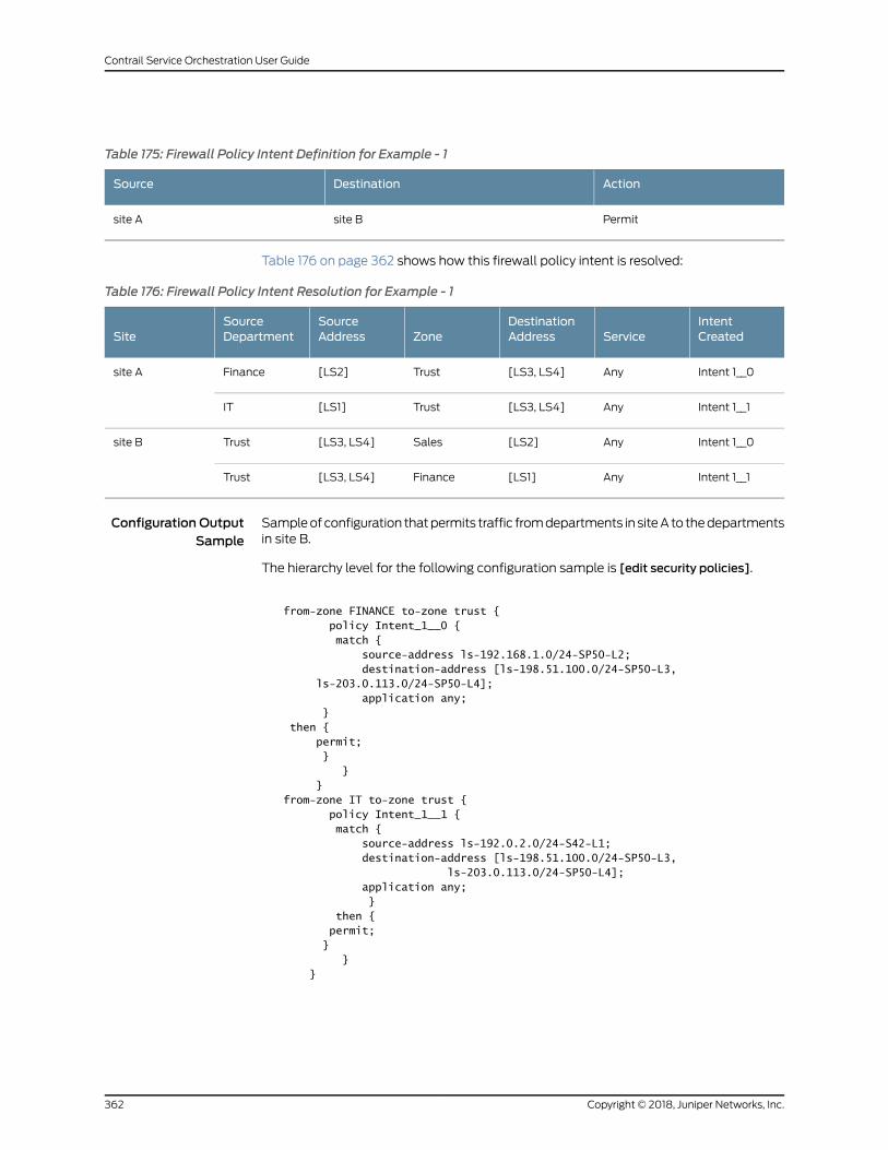
Table 175: Firewall Policy Intent Definition for Example - 1
ActionDestinationSource
Permitsite Bsite A
Table 176 on page 362 shows how this firewall policy intent is resolved:
Table 176: Firewall Policy Intent Resolution for Example - 1
IntentCreatedService
DestinationAddressZone
SourceAddress
SourceDepartmentSite
Intent 1__0Any[LS3, LS4]Trust[LS2]Financesite A
Intent 1__1Any[LS3, LS4]Trust[LS1]IT
Intent 1__0Any[LS2]Sales[LS3, LS4]Trustsite B
Intent 1__1Any[LS1]Finance[LS3, LS4]Trust
Configuration OutputSample
Sampleofconfiguration thatpermits traffic fromdepartments in siteA to thedepartmentsin site B.
The hierarchy level for the following configuration sample is [edit security policies].
from-zone FINANCE to-zone trust { policy Intent_1__0 { match { source-address ls-192.168.1.0/24-SP50-L2; destination-address [ls-198.51.100.0/24-SP50-L3, ls-203.0.113.0/24-SP50-L4]; application any; } then { permit; } } }from-zone IT to-zone trust { policy Intent_1__1 { match { source-address ls-192.0.2.0/24-S42-L1; destination-address [ls-198.51.100.0/24-SP50-L3, ls-203.0.113.0/24-SP50-L4]; application any; } then { permit; } } }
Copyright © 2018, Juniper Networks, Inc.362
Contrail Service Orchestration User Guide
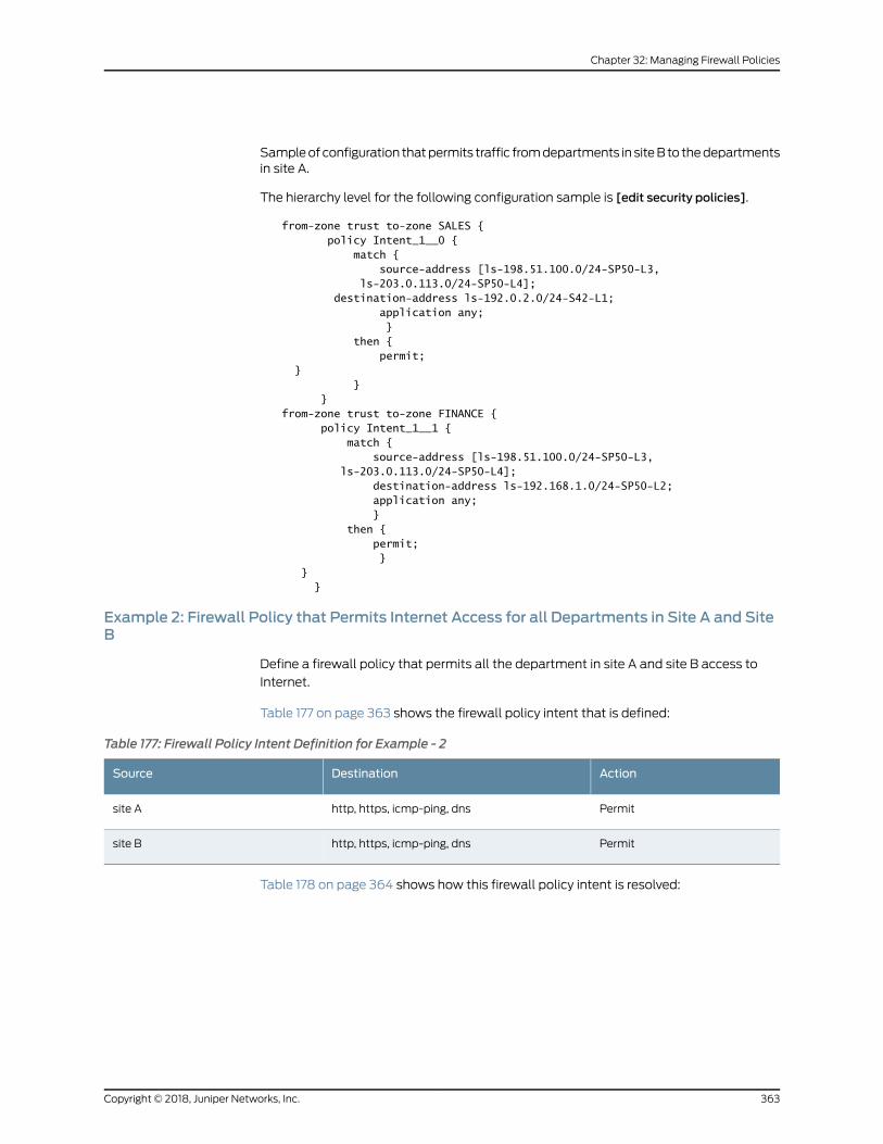
Sampleofconfiguration thatpermits traffic fromdepartments in siteB to thedepartmentsin site A.
The hierarchy level for the following configuration sample is [edit security policies].
from-zone trust to-zone SALES { policy Intent_1__0 { match { source-address [ls-198.51.100.0/24-SP50-L3, ls-203.0.113.0/24-SP50-L4]; destination-address ls-192.0.2.0/24-S42-L1; application any; } then { permit; } } }from-zone trust to-zone FINANCE { policy Intent_1__1 { match { source-address [ls-198.51.100.0/24-SP50-L3, ls-203.0.113.0/24-SP50-L4]; destination-address ls-192.168.1.0/24-SP50-L2; application any; } then { permit; } } }
Example 2: Firewall Policy that Permits Internet Access for all Departments in Site A and SiteB
Define a firewall policy that permits all the department in site A and site B access to
Internet.
Table 177 on page 363 shows the firewall policy intent that is defined:
Table 177: Firewall Policy Intent Definition for Example - 2
ActionDestinationSource
Permithttp, https, icmp-ping, dnssite A
Permithttp, https, icmp-ping, dnssite B
Table 178 on page 364 shows how this firewall policy intent is resolved:
363Copyright © 2018, Juniper Networks, Inc.
Chapter 32: Managing Firewall Policies
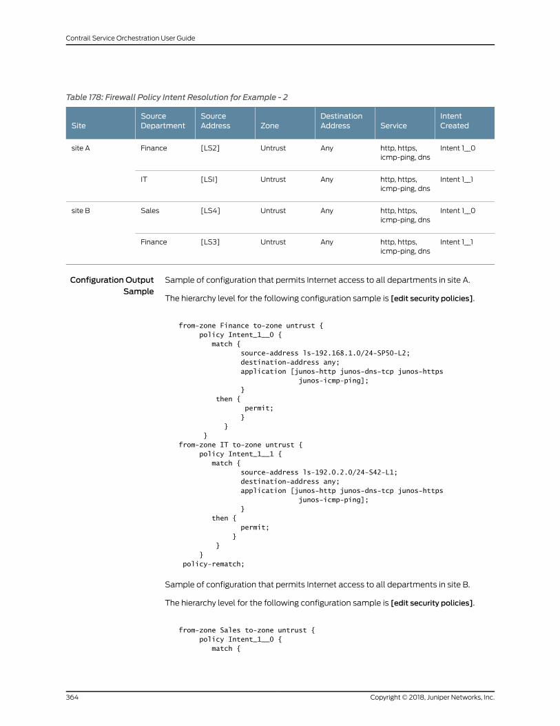
Table 178: Firewall Policy Intent Resolution for Example - 2
IntentCreatedService
DestinationAddressZone
SourceAddress
SourceDepartmentSite
Intent 1__0http, https,icmp-ping, dns
AnyUntrust[LS2]Financesite A
Intent 1__1http, https,icmp-ping, dns
AnyUntrust[LSI]IT
Intent 1__0http, https,icmp-ping, dns
AnyUntrust[LS4]Salessite B
Intent 1__1http, https,icmp-ping, dns
AnyUntrust[LS3]Finance
Configuration OutputSample
Sample of configuration that permits Internet access to all departments in site A.
The hierarchy level for the following configuration sample is [edit security policies].
from-zone Finance to-zone untrust { policy Intent_1__0 { match { source-address ls-192.168.1.0/24-SP50-L2; destination-address any; application [junos-http junos-dns-tcp junos-https junos-icmp-ping]; } then { permit; } } }from-zone IT to-zone untrust { policy Intent_1__1 { match { source-address ls-192.0.2.0/24-S42-L1; destination-address any; application [junos-http junos-dns-tcp junos-https junos-icmp-ping]; } then { permit; } } } policy-rematch;
Sample of configuration that permits Internet access to all departments in site B.
The hierarchy level for the following configuration sample is [edit security policies].
from-zone Sales to-zone untrust { policy Intent_1__0 { match {
Copyright © 2018, Juniper Networks, Inc.364
Contrail Service Orchestration User Guide
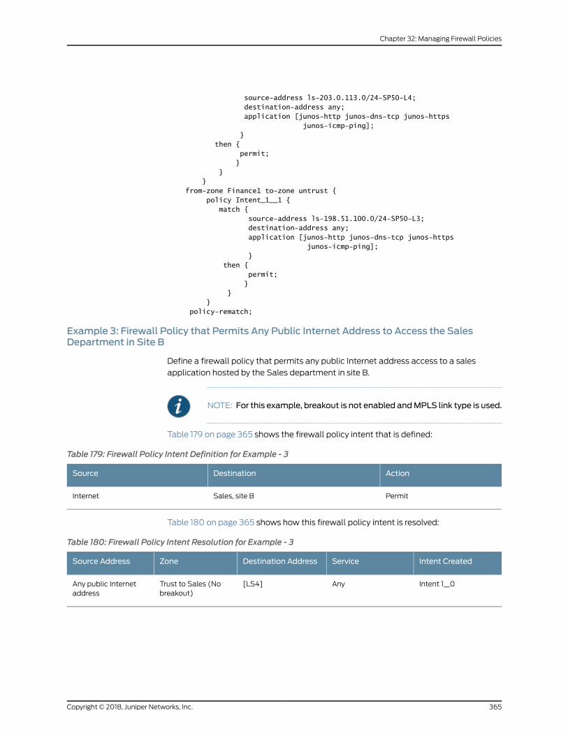
source-address ls-203.0.113.0/24-SP50-L4; destination-address any; application [junos-http junos-dns-tcp junos-https junos-icmp-ping]; } then { permit; } } } from-zone Finance1 to-zone untrust { policy Intent_1__1 { match { source-address ls-198.51.100.0/24-SP50-L3; destination-address any; application [junos-http junos-dns-tcp junos-https junos-icmp-ping]; } then { permit; } } } policy-rematch;
Example 3: Firewall Policy that Permits Any Public Internet Address to Access the SalesDepartment in Site B
Define a firewall policy that permits any public Internet address access to a sales
application hosted by the Sales department in site B.
NOTE: For this example, breakout is not enabled andMPLS link type is used.
Table 179 on page 365 shows the firewall policy intent that is defined:
Table 179: Firewall Policy Intent Definition for Example - 3
ActionDestinationSource
PermitSales, site BInternet
Table 180 on page 365 shows how this firewall policy intent is resolved:
Table 180: Firewall Policy Intent Resolution for Example - 3
Intent CreatedServiceDestination AddressZoneSource Address
Intent 1__0Any[LS4]Trust to Sales (Nobreakout)
Any public Internetaddress
365Copyright © 2018, Juniper Networks, Inc.
Chapter 32: Managing Firewall Policies
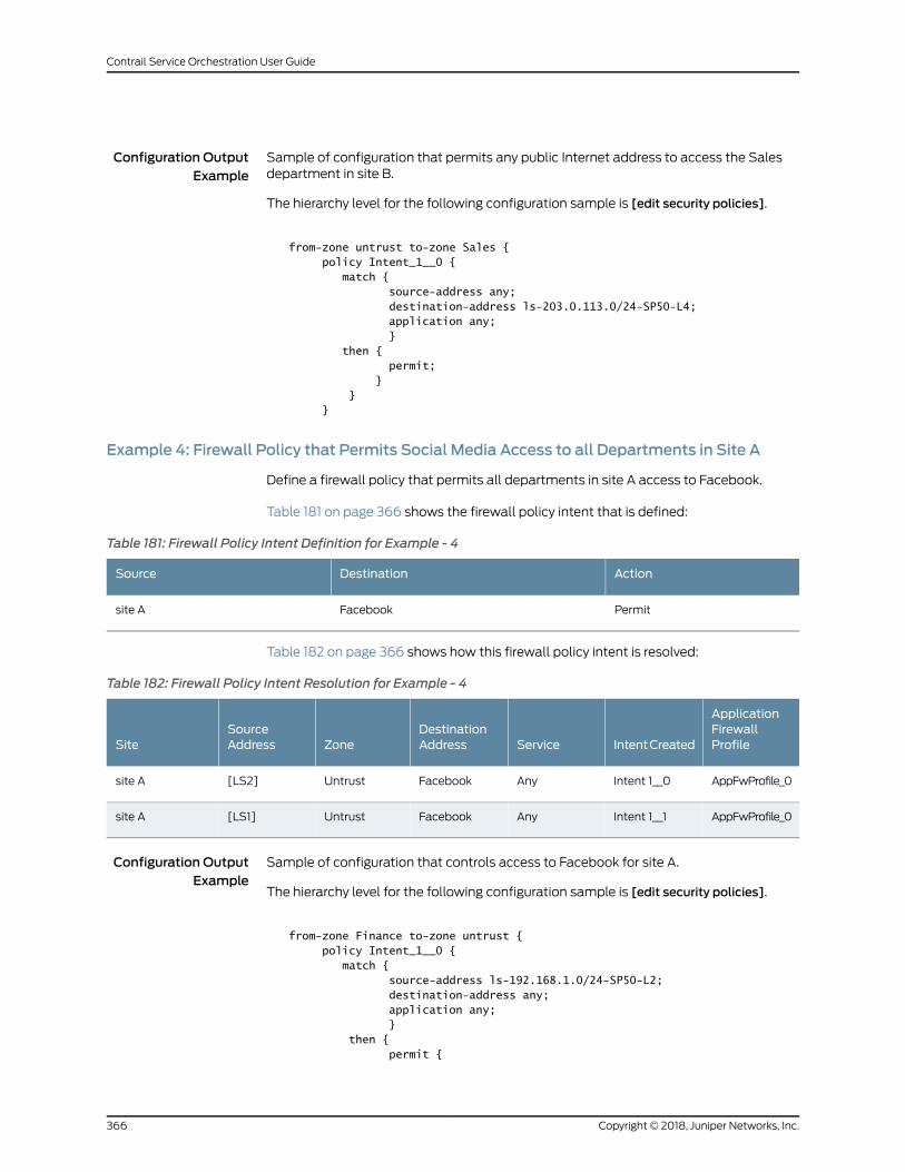
Configuration OutputExample
Sample of configuration that permits any public Internet address to access the Salesdepartment in site B.
The hierarchy level for the following configuration sample is [edit security policies].
from-zone untrust to-zone Sales { policy Intent_1__0 { match { source-address any; destination-address ls-203.0.113.0/24-SP50-L4; application any; } then { permit; } } }
Example 4: Firewall Policy that Permits Social Media Access to all Departments in Site A
Define a firewall policy that permits all departments in site A access to Facebook.
Table 181 on page 366 shows the firewall policy intent that is defined:
Table 181: Firewall Policy Intent Definition for Example - 4
ActionDestinationSource
PermitFacebooksite A
Table 182 on page 366 shows how this firewall policy intent is resolved:
Table 182: Firewall Policy Intent Resolution for Example - 4
ApplicationFirewallProfileIntentCreatedService
DestinationAddressZone
SourceAddressSite
AppFwProfile_0Intent 1__0AnyFacebookUntrust[LS2]site A
AppFwProfile_0Intent 1__1AnyFacebookUntrust[LS1]site A
Configuration OutputExample
Sample of configuration that controls access to Facebook for site A.
The hierarchy level for the following configuration sample is [edit security policies].
from-zone Finance to-zone untrust { policy Intent_1__0 { match { source-address ls-192.168.1.0/24-SP50-L2; destination-address any; application any; } then { permit {
Copyright © 2018, Juniper Networks, Inc.366
Contrail Service Orchestration User Guide
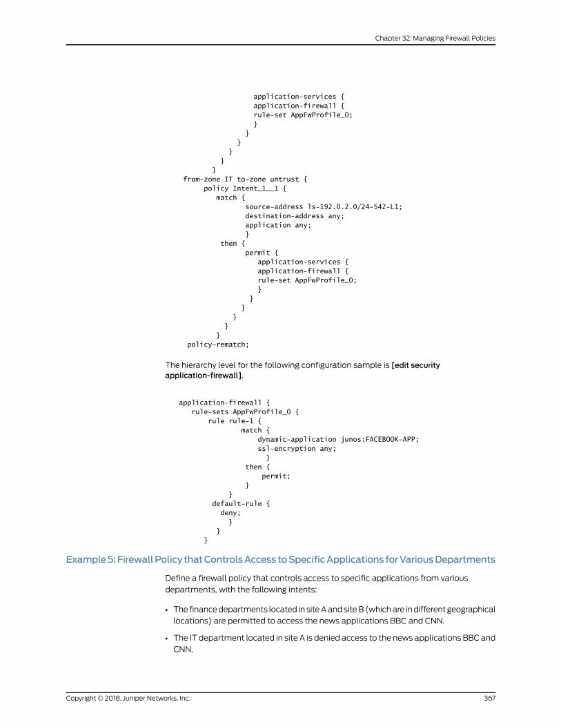
application-services { application-firewall { rule-set AppFwProfile_0; } } } } } } from-zone IT to-zone untrust { policy Intent_1__1 { match { source-address ls-192.0.2.0/24-S42-L1; destination-address any; application any; } then { permit { application-services { application-firewall { rule-set AppFwProfile_0; } } } } } } policy-rematch;
The hierarchy level for the following configuration sample is [edit securityapplication-firewall].
application-firewall { rule-sets AppFwProfile_0 { rule rule-1 { match { dynamic-application junos:FACEBOOK-APP; ssl-encryption any; } then { permit; } } default-rule { deny; } } }
Example5:FirewallPolicy thatControlsAccesstoSpecificApplicationsforVariousDepartments
Define a firewall policy that controls access to specific applications from various
departments, with the following intents:
• The financedepartments located in siteAandsiteB(whichare indifferentgeographical
locations) are permitted to access the news applications BBC and CNN.
• The IT department located in site A is denied access to the news applications BBC and
CNN.
367Copyright © 2018, Juniper Networks, Inc.
Chapter 32: Managing Firewall Policies
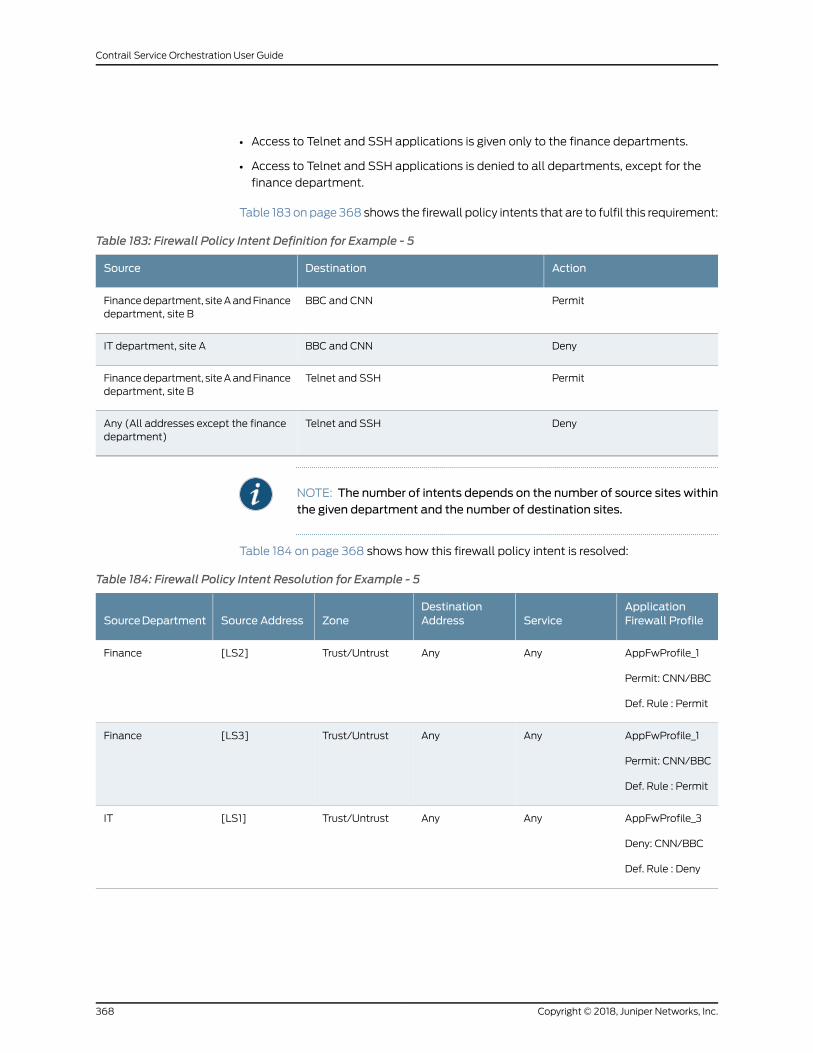
• Access to Telnet and SSH applications is given only to the finance departments.
• Access to Telnet and SSH applications is denied to all departments, except for the
finance department.
Table 183 on page 368 shows the firewall policy intents that are to fulfil this requirement:
Table 183: Firewall Policy Intent Definition for Example - 5
ActionDestinationSource
PermitBBC and CNNFinancedepartment, siteAandFinancedepartment, site B
DenyBBC and CNNIT department, site A
PermitTelnet and SSHFinancedepartment, siteAandFinancedepartment, site B
DenyTelnet and SSHAny (All addresses except the financedepartment)
NOTE: The number of intents depends on the number of source sites withinthe given department and the number of destination sites.
Table 184 on page 368 shows how this firewall policy intent is resolved:
Table 184: Firewall Policy Intent Resolution for Example - 5
ApplicationFirewall ProfileService
DestinationAddressZoneSource AddressSourceDepartment
AppFwProfile_1
Permit: CNN/BBC
Def. Rule : Permit
AnyAnyTrust/Untrust[LS2]Finance
AppFwProfile_1
Permit: CNN/BBC
Def. Rule : Permit
AnyAnyTrust/Untrust[LS3]Finance
AppFwProfile_3
Deny: CNN/BBC
Def. Rule : Deny
AnyAnyTrust/Untrust[LS1]IT
Copyright © 2018, Juniper Networks, Inc.368
Contrail Service Orchestration User Guide
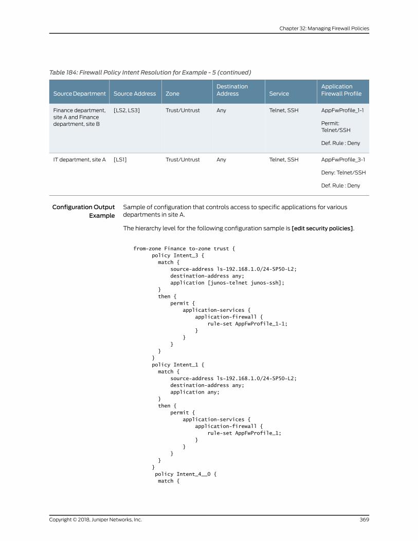
Table 184: Firewall Policy Intent Resolution for Example - 5 (continued)
ApplicationFirewall ProfileService
DestinationAddressZoneSource AddressSourceDepartment
AppFwProfile_1-1
Permit:Telnet/SSH
Def. Rule : Deny
Telnet, SSHAnyTrust/Untrust[LS2, LS3]Finance department,site A and Financedepartment, site B
AppFwProfile_3-1
Deny: Telnet/SSH
Def. Rule : Deny
Telnet, SSHAnyTrust/Untrust[LS1]IT department, site A
Configuration OutputExample
Sample of configuration that controls access to specific applications for variousdepartments in site A.
The hierarchy level for the following configuration sample is [edit security policies].
from-zone Finance to-zone trust { policy Intent_3 { match { source-address ls-192.168.1.0/24-SP50-L2; destination-address any; application [junos-telnet junos-ssh]; } then { permit { application-services { application-firewall { rule-set AppFwProfile_1-1; } } } } } policy Intent_1 { match { source-address ls-192.168.1.0/24-SP50-L2; destination-address any; application any; } then { permit { application-services { application-firewall { rule-set AppFwProfile_1; } } } } } policy Intent_4__0 { match {
369Copyright © 2018, Juniper Networks, Inc.
Chapter 32: Managing Firewall Policies
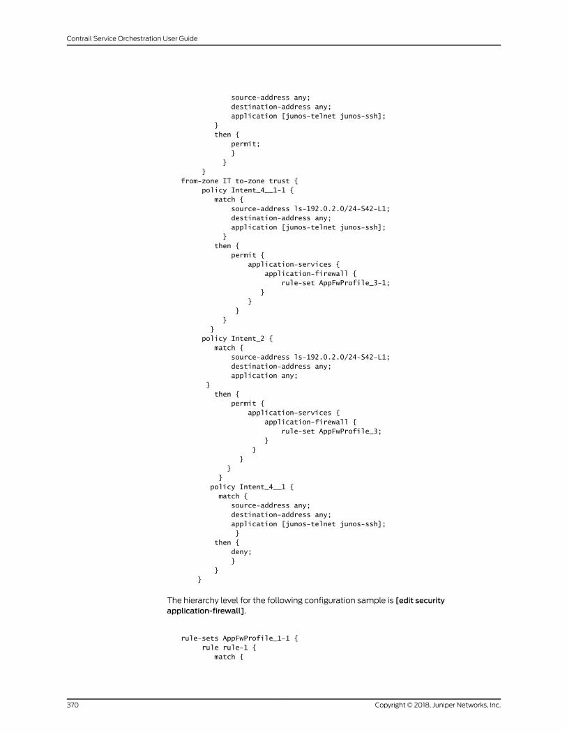
source-address any; destination-address any; application [junos-telnet junos-ssh]; } then { permit; } } }from-zone IT to-zone trust { policy Intent_4__1-1 { match { source-address ls-192.0.2.0/24-S42-L1; destination-address any; application [junos-telnet junos-ssh]; } then { permit { application-services { application-firewall { rule-set AppFwProfile_3-1; } } } } } policy Intent_2 { match { source-address ls-192.0.2.0/24-S42-L1; destination-address any; application any; } then { permit { application-services { application-firewall { rule-set AppFwProfile_3; } } } } } policy Intent_4__1 { match { source-address any; destination-address any; application [junos-telnet junos-ssh]; } then { deny; } } }
The hierarchy level for the following configuration sample is [edit securityapplication-firewall].
rule-sets AppFwProfile_1-1 { rule rule-1 { match {
Copyright © 2018, Juniper Networks, Inc.370
Contrail Service Orchestration User Guide
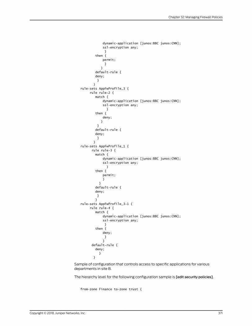
dynamic-application [junos:BBC junos:CNN]; ssl-encryption any; } then { permit; } } default-rule { deny; } }rule-sets AppFwProfile_3 { rule rule-2 { match { dynamic-application [junos:BBC junos:CNN]; ssl-encryption any; } then { deny; } } default-rule { deny; } }rule-sets AppFwProfile_1 { rule rule-3 { match { dynamic-application [junos:BBC junos:CNN]; ssl-encryption any; } then { permit; } } default-rule { deny; } }rule-sets AppFwProfile_3-1 { rule rule-4 { match { dynamic-application [junos:BBC junos:CNN]; ssl-encryption any; } then { deny; } } default-rule { deny; } }
Sample of configuration that controls access to specific applications for variousdepartments in site B.
The hierarchy level for the following configuration sample is [edit security policies].
from-zone Finance to-zone trust {
371Copyright © 2018, Juniper Networks, Inc.
Chapter 32: Managing Firewall Policies
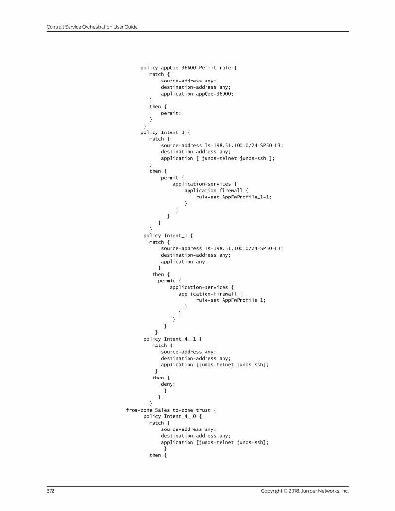
policy appQoe-36600-Permit-rule { match { source-address any; destination-address any; application appQoe-36000; } then { permit; } } policy Intent_3 { match { source-address ls-198.51.100.0/24-SP50-L3; destination-address any; application [ junos-telnet junos-ssh ]; } then { permit { application-services { application-firewall { rule-set AppFwProfile_1-1; } } } } } policy Intent_1 { match { source-address ls-198.51.100.0/24-SP50-L3; destination-address any; application any; } then { permit { application-services { application-firewall { rule-set AppFwProfile_1; } } } } } policy Intent_4__1 { match { source-address any; destination-address any; application [junos-telnet junos-ssh]; } then { deny; } } }from-zone Sales to-zone trust { policy Intent_4__0 { match { source-address any; destination-address any; application [junos-telnet junos-ssh]; } then {
Copyright © 2018, Juniper Networks, Inc.372
Contrail Service Orchestration User Guide
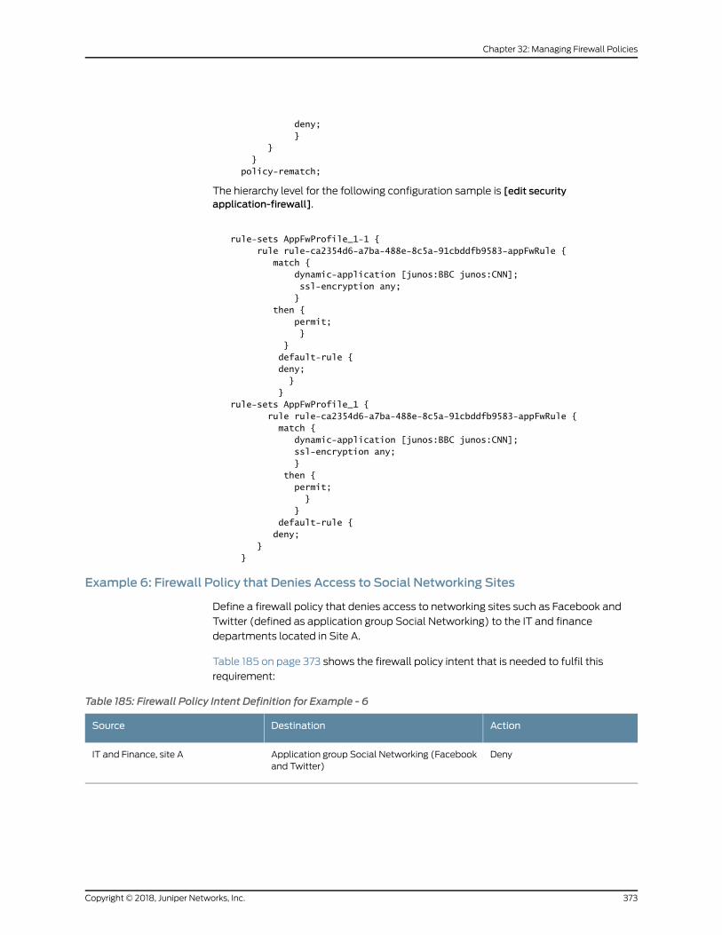
deny; } } } policy-rematch;
The hierarchy level for the following configuration sample is [edit securityapplication-firewall].
rule-sets AppFwProfile_1-1 { rule rule-ca2354d6-a7ba-488e-8c5a-91cbddfb9583-appFwRule { match { dynamic-application [junos:BBC junos:CNN]; ssl-encryption any; } then { permit; } } default-rule { deny; } }rule-sets AppFwProfile_1 { rule rule-ca2354d6-a7ba-488e-8c5a-91cbddfb9583-appFwRule { match { dynamic-application [junos:BBC junos:CNN]; ssl-encryption any; } then { permit; } } default-rule { deny; } }
Example 6: Firewall Policy that Denies Access to Social Networking Sites
Define a firewall policy that denies access to networking sites such as Facebook and
Twitter (defined as application group Social Networking) to the IT and finance
departments located in Site A.
Table 185 on page 373 shows the firewall policy intent that is needed to fulfil this
requirement:
Table 185: Firewall Policy Intent Definition for Example - 6
ActionDestinationSource
DenyApplication group Social Networking (Facebookand Twitter)
IT and Finance, site A
373Copyright © 2018, Juniper Networks, Inc.
Chapter 32: Managing Firewall Policies
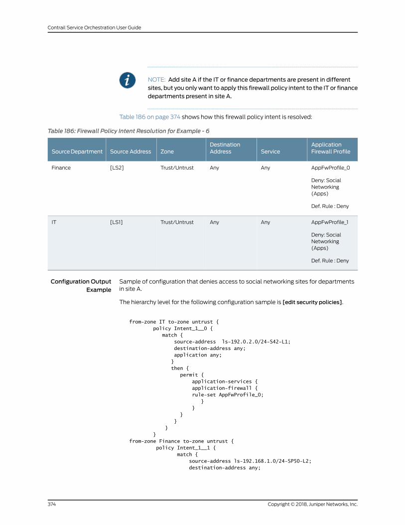
NOTE: Add site A if the IT or finance departments are present in differentsites, but you onlywant to apply this firewall policy intent to the IT or financedepartments present in site A.
Table 186 on page 374 shows how this firewall policy intent is resolved:
Table 186: Firewall Policy Intent Resolution for Example - 6
ApplicationFirewall ProfileService
DestinationAddressZoneSource AddressSourceDepartment
AppFwProfile_0
Deny: SocialNetworking(Apps)
Def. Rule : Deny
AnyAnyTrust/Untrust[LS2]Finance
AppFwProfile_1
Deny: SocialNetworking(Apps)
Def. Rule : Deny
AnyAnyTrust/Untrust[LS1]IT
Configuration OutputExample
Sample of configuration that denies access to social networking sites for departmentsin site A.
The hierarchy level for the following configuration sample is [edit security policies].
from-zone IT to-zone untrust { policy Intent_1__0 { match { source-address ls-192.0.2.0/24-S42-L1; destination-address any; application any; } then { permit { application-services { application-firewall { rule-set AppFwProfile_0; } } } } } }from-zone Finance to-zone untrust { policy Intent_1__1 { match { source-address ls-192.168.1.0/24-SP50-L2; destination-address any;
Copyright © 2018, Juniper Networks, Inc.374
Contrail Service Orchestration User Guide
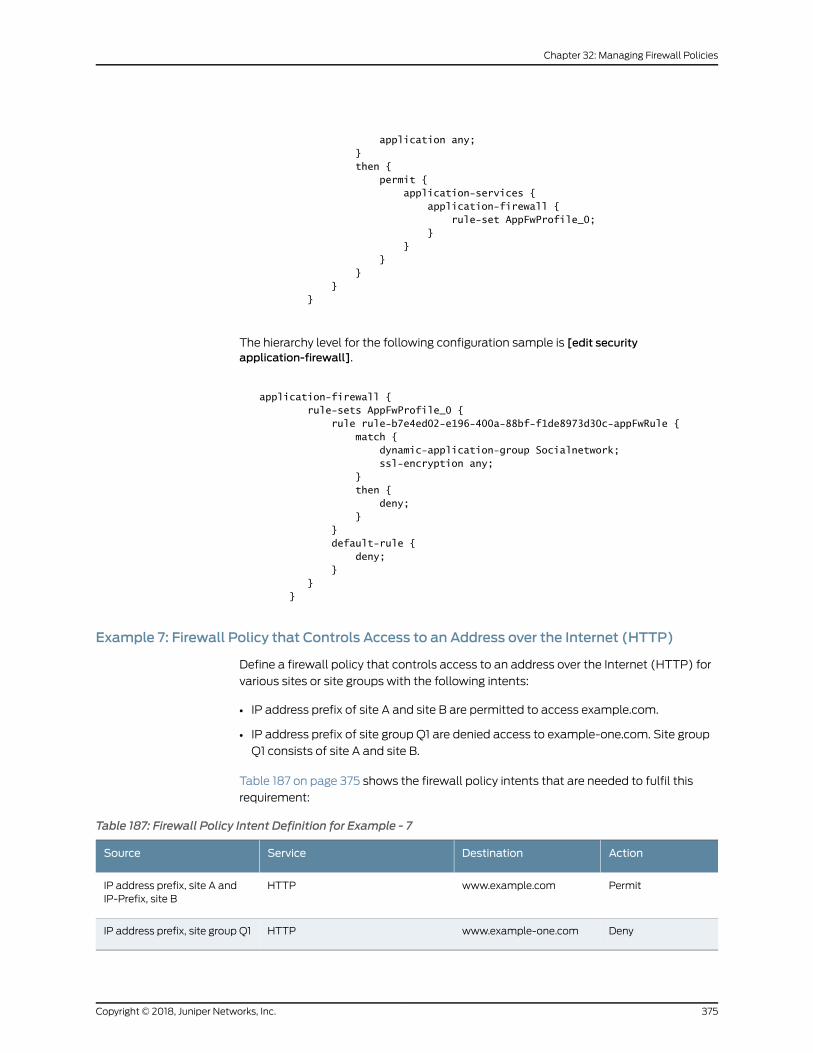
application any; } then { permit { application-services { application-firewall { rule-set AppFwProfile_0; } } } } } }
The hierarchy level for the following configuration sample is [edit securityapplication-firewall].
application-firewall { rule-sets AppFwProfile_0 { rule rule-b7e4ed02-e196-400a-88bf-f1de8973d30c-appFwRule { match { dynamic-application-group Socialnetwork; ssl-encryption any; } then { deny; } } default-rule { deny; } } }
Example 7: Firewall Policy that Controls Access to an Address over the Internet (HTTP)
Define a firewall policy that controls access to an address over the Internet (HTTP) for
various sites or site groups with the following intents:
• IP address prefix of site A and site B are permitted to access example.com.
• IP address prefix of site group Q1 are denied access to example-one.com. Site group
Q1 consists of site A and site B.
Table 187 on page 375 shows the firewall policy intents that are needed to fulfil this
requirement:
Table 187: Firewall Policy Intent Definition for Example - 7
ActionDestinationServiceSource
Permitwww.example.comHTTPIP address prefix, site A andIP-Prefix, site B
Denywww.example-one.comHTTPIP address prefix, site group Q1
375Copyright © 2018, Juniper Networks, Inc.
Chapter 32: Managing Firewall Policies
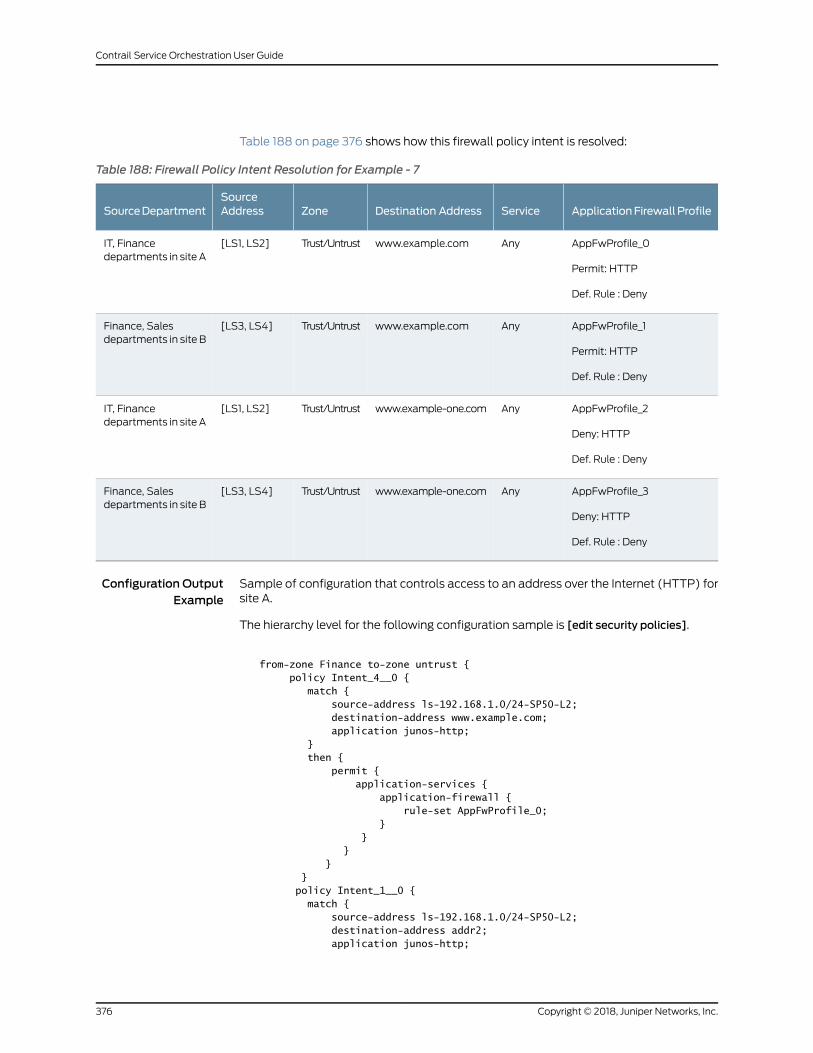
Table 188 on page 376 shows how this firewall policy intent is resolved:
Table 188: Firewall Policy Intent Resolution for Example - 7
ApplicationFirewallProfileServiceDestination AddressZoneSourceAddressSourceDepartment
AppFwProfile_0
Permit: HTTP
Def. Rule : Deny
Anywww.example.comTrust/Untrust[LS1, LS2]IT, Financedepartments in site A
AppFwProfile_1
Permit: HTTP
Def. Rule : Deny
Anywww.example.comTrust/Untrust[LS3, LS4]Finance, Salesdepartments in site B
AppFwProfile_2
Deny: HTTP
Def. Rule : Deny
Anywww.example-one.comTrust/Untrust[LS1, LS2]IT, Financedepartments in site A
AppFwProfile_3
Deny: HTTP
Def. Rule : Deny
Anywww.example-one.comTrust/Untrust[LS3, LS4]Finance, Salesdepartments in site B
Configuration OutputExample
Sample of configuration that controls access to an address over the Internet (HTTP) forsite A.
The hierarchy level for the following configuration sample is [edit security policies].
from-zone Finance to-zone untrust { policy Intent_4__0 { match { source-address ls-192.168.1.0/24-SP50-L2; destination-address www.example.com; application junos-http; } then { permit { application-services { application-firewall { rule-set AppFwProfile_0; } } } } } policy Intent_1__0 { match { source-address ls-192.168.1.0/24-SP50-L2; destination-address addr2; application junos-http;
Copyright © 2018, Juniper Networks, Inc.376
Contrail Service Orchestration User Guide
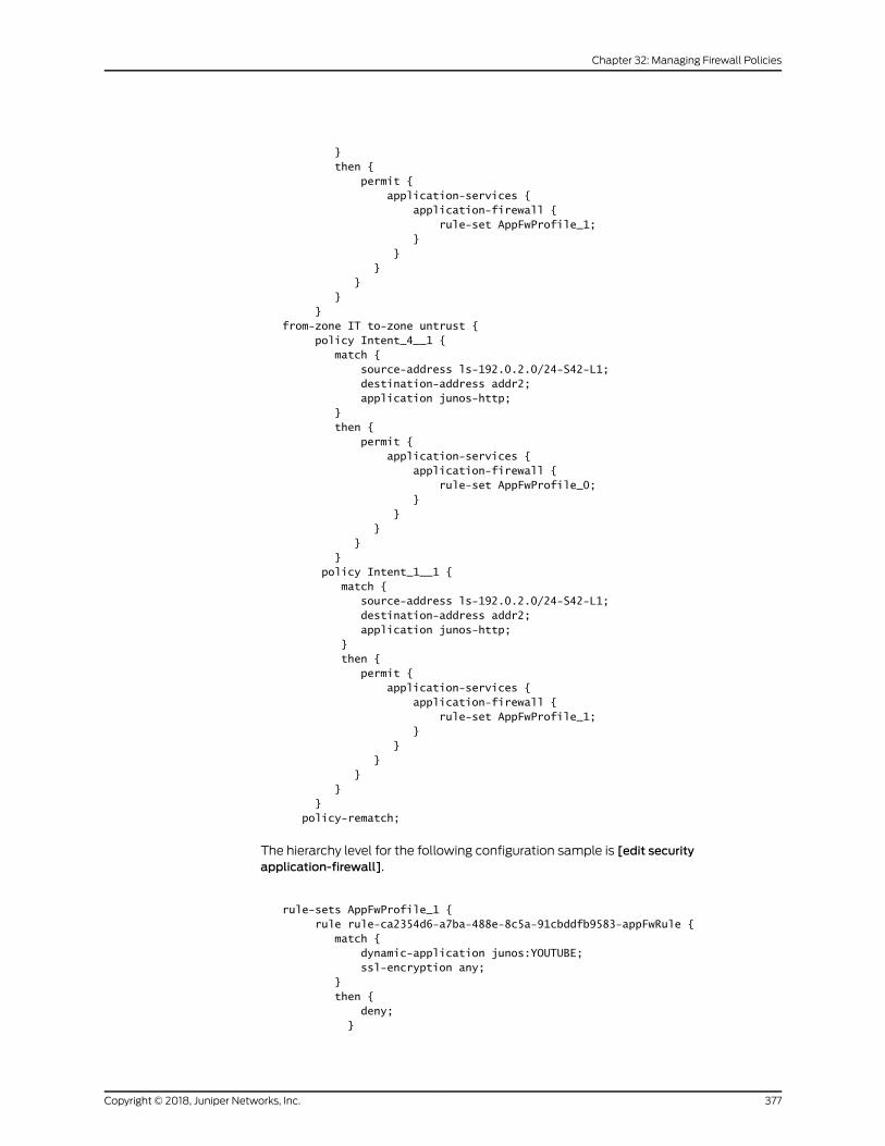
} then { permit { application-services { application-firewall { rule-set AppFwProfile_1; } } } } } }from-zone IT to-zone untrust { policy Intent_4__1 { match { source-address ls-192.0.2.0/24-S42-L1; destination-address addr2; application junos-http; } then { permit { application-services { application-firewall { rule-set AppFwProfile_0; } } } } } policy Intent_1__1 { match { source-address ls-192.0.2.0/24-S42-L1; destination-address addr2; application junos-http; } then { permit { application-services { application-firewall { rule-set AppFwProfile_1; } } } } } } policy-rematch;
The hierarchy level for the following configuration sample is [edit securityapplication-firewall].
rule-sets AppFwProfile_1 { rule rule-ca2354d6-a7ba-488e-8c5a-91cbddfb9583-appFwRule { match { dynamic-application junos:YOUTUBE; ssl-encryption any; } then { deny; }
377Copyright © 2018, Juniper Networks, Inc.
Chapter 32: Managing Firewall Policies
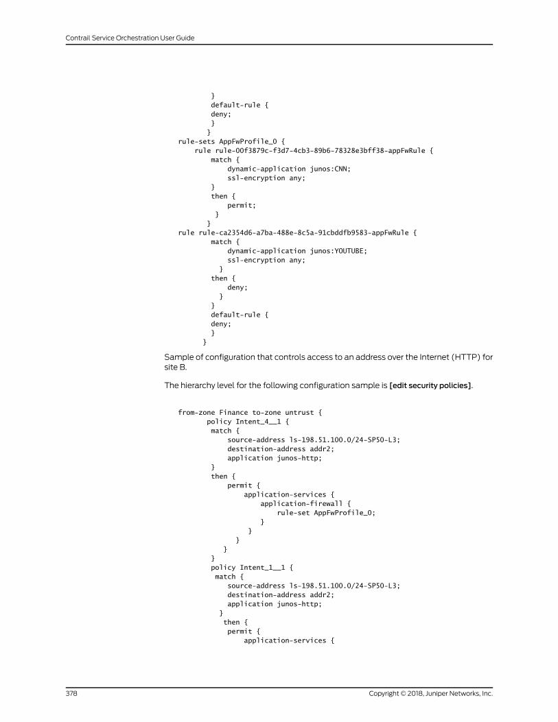
} default-rule { deny; } }rule-sets AppFwProfile_0 { rule rule-00f3879c-f3d7-4cb3-89b6-78328e3bff38-appFwRule { match { dynamic-application junos:CNN; ssl-encryption any; } then { permit; } }rule rule-ca2354d6-a7ba-488e-8c5a-91cbddfb9583-appFwRule { match { dynamic-application junos:YOUTUBE; ssl-encryption any; } then { deny; } } default-rule { deny; } }
Sample of configuration that controls access to an address over the Internet (HTTP) forsite B.
The hierarchy level for the following configuration sample is [edit security policies].
from-zone Finance to-zone untrust { policy Intent_4__1 { match { source-address ls-198.51.100.0/24-SP50-L3; destination-address addr2; application junos-http; } then { permit { application-services { application-firewall { rule-set AppFwProfile_0; } } } } } policy Intent_1__1 { match { source-address ls-198.51.100.0/24-SP50-L3; destination-address addr2; application junos-http; } then { permit { application-services {
Copyright © 2018, Juniper Networks, Inc.378
Contrail Service Orchestration User Guide
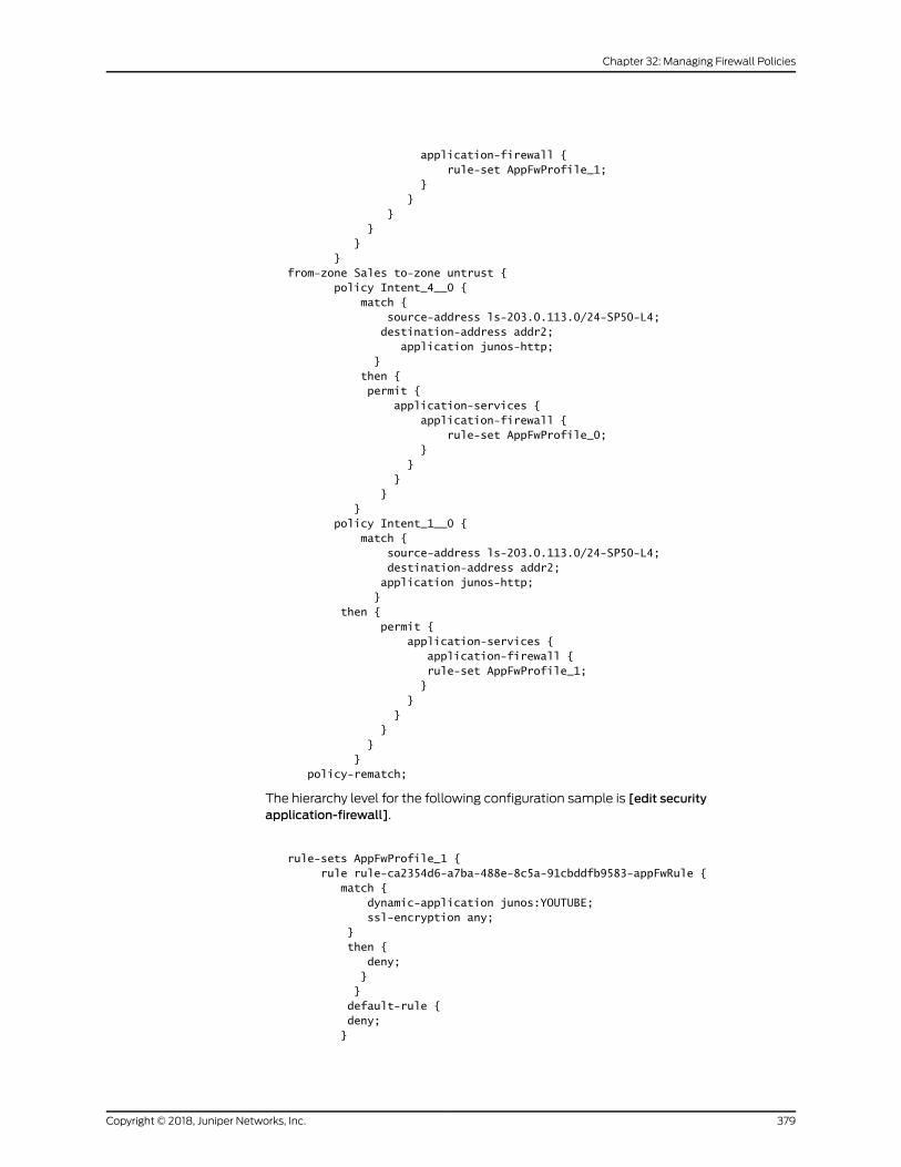
application-firewall { rule-set AppFwProfile_1; } } } } } }from-zone Sales to-zone untrust { policy Intent_4__0 { match { source-address ls-203.0.113.0/24-SP50-L4; destination-address addr2; application junos-http; } then { permit { application-services { application-firewall { rule-set AppFwProfile_0; } } } } } policy Intent_1__0 { match { source-address ls-203.0.113.0/24-SP50-L4; destination-address addr2; application junos-http; } then { permit { application-services { application-firewall { rule-set AppFwProfile_1; } } } } } } policy-rematch;
The hierarchy level for the following configuration sample is [edit securityapplication-firewall].
rule-sets AppFwProfile_1 { rule rule-ca2354d6-a7ba-488e-8c5a-91cbddfb9583-appFwRule { match { dynamic-application junos:YOUTUBE; ssl-encryption any; } then { deny; } } default-rule { deny; }
379Copyright © 2018, Juniper Networks, Inc.
Chapter 32: Managing Firewall Policies
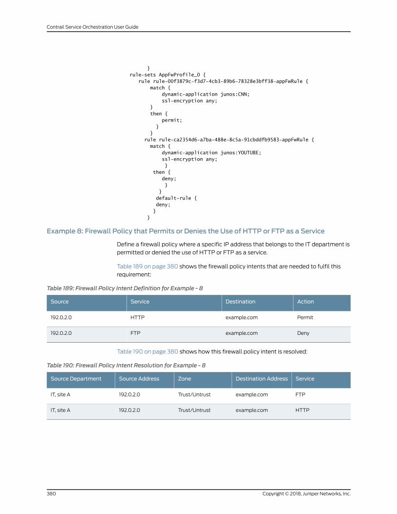
} rule-sets AppFwProfile_0 { rule rule-00f3879c-f3d7-4cb3-89b6-78328e3bff38-appFwRule { match { dynamic-application junos:CNN; ssl-encryption any; } then { permit; } } rule rule-ca2354d6-a7ba-488e-8c5a-91cbddfb9583-appFwRule { match { dynamic-application junos:YOUTUBE; ssl-encryption any; } then { deny; } } default-rule { deny; } }
Example 8: Firewall Policy that Permits or Denies the Use of HTTP or FTP as a Service
Define a firewall policy where a specific IP address that belongs to the IT department is
permitted or denied the use of HTTP or FTP as a service.
Table 189 on page 380 shows the firewall policy intents that are needed to fulfil this
requirement:
Table 189: Firewall Policy Intent Definition for Example - 8
ActionDestinationServiceSource
Permitexample.comHTTP192.0.2.0
Denyexample.comFTP192.0.2.0
Table 190 on page 380 shows how this firewall policy intent is resolved:
Table 190: Firewall Policy Intent Resolution for Example - 8
ServiceDestination AddressZoneSource AddressSource Department
FTPexample.comTrust/Untrust192.0.2.0IT, site A
HTTPexample.comTrust/Untrust192.0.2.0IT, site A
Copyright © 2018, Juniper Networks, Inc.380
Contrail Service Orchestration User Guide
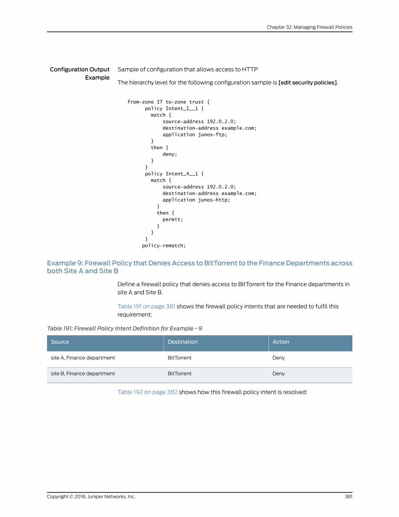
Configuration OutputExample
Sample of configuration that allows access to HTTP
The hierarchy level for the following configuration sample is [edit security policies].
from-zone IT to-zone trust { policy Intent_1__1 { match { source-address 192.0.2.0; destination-address example.com; application junos-ftp; } then { deny; } } policy Intent_4__1 { match { source-address 192.0.2.0; destination-address example.com; application junos-http; } then { permit; } } } policy-rematch;
Example9: Firewall Policy thatDeniesAccess toBitTorrent to the FinanceDepartments acrossboth Site A and Site B
Define a firewall policy that denies access to BitTorrent for the Finance departments in
site A and Site B.
Table 191 on page 381 shows the firewall policy intents that are needed to fulfil this
requirement:
Table 191: Firewall Policy Intent Definition for Example - 9
ActionDestinationSource
DenyBitTorrentsite A, Finance department
DenyBitTorrentsite B, Finance department
Table 192 on page 382 shows how this firewall policy intent is resolved:
381Copyright © 2018, Juniper Networks, Inc.
Chapter 32: Managing Firewall Policies
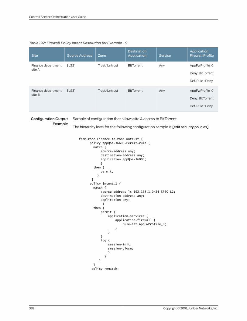
Table 192: Firewall Policy Intent Resolution for Example - 9
ApplicationFirewall ProfileService
DestinationApplicationZoneSource AddressSite
AppFwProfile_0
Deny: BitTorrent
Def. Rule : Deny
AnyBitTorrentTrust/Untrust[LS2]Finance department,site A
AppFwProfile_0
Deny: BitTorrent
Def. Rule : Deny
AnyBitTorrentTrust/Untrust[LS3]Finance department,site B
Configuration OutputExample
Sample of configuration that allows site A access to BitTorrent.
The hierarchy level for the following configuration sample is [edit security policies].
from-zone Finance to-zone untrust { policy appQoe-36600-Permit-rule { match { source-address any; destination-address any; application appQoe-36000; } then { permit; } } policy Intent_1 { match { source-address ls-192.168.1.0/24-SP50-L2; destination-address any; application any; } then { permit { application-services { application-firewall { rule-set AppFwProfile_0; } } } log { session-init; session-close; } } } } policy-rematch;
Copyright © 2018, Juniper Networks, Inc.382
Contrail Service Orchestration User Guide
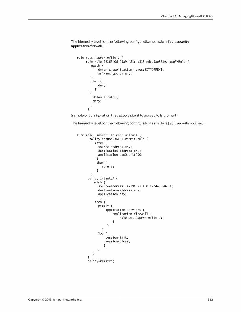
The hierarchy level for the following configuration sample is [edit securityapplication-firewall].
rule-sets AppFwProfile_0 { rule rule-2226740d-03a9-483c-b315-eddc9ae8619a-appFwRule { match { dynamic-application junos:BITTORRENT; ssl-encryption any; } then { deny; } } default-rule { deny; } }
Sample of configuration that allows site B to access to BitTorrent.
The hierarchy level for the following configuration sample is [edit security policies].
from-zone Finance1 to-zone untrust { policy appQoe-36600-Permit-rule { match { source-address any; destination-address any; application appQoe-36000; } then { permit; } } policy Intent_4 { match { source-address ls-198.51.100.0/24-SP50-L3; destination-address any; application any; } then { permit { application-services { application-firewall { rule-set AppFwProfile_0; } } } log { session-init; session-close; } } } } policy-rematch;
383Copyright © 2018, Juniper Networks, Inc.
Chapter 32: Managing Firewall Policies
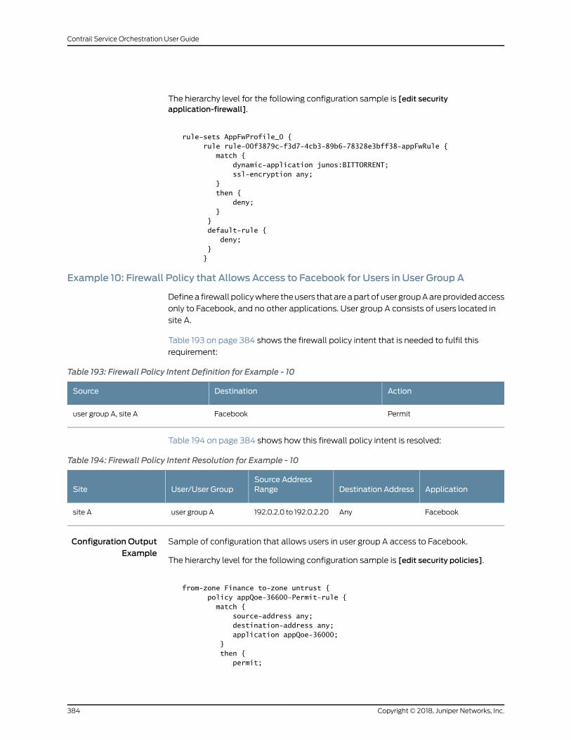
The hierarchy level for the following configuration sample is [edit securityapplication-firewall].
rule-sets AppFwProfile_0 { rule rule-00f3879c-f3d7-4cb3-89b6-78328e3bff38-appFwRule { match { dynamic-application junos:BITTORRENT; ssl-encryption any; } then { deny; } } default-rule { deny; } }
Example 10: Firewall Policy that Allows Access to Facebook for Users in User Group A
Definea firewall policywhere theusers thatareapart of user groupAareprovidedaccess
only to Facebook, and no other applications. User group A consists of users located in
site A.
Table 193 on page 384 shows the firewall policy intent that is needed to fulfil this
requirement:
Table 193: Firewall Policy Intent Definition for Example - 10
ActionDestinationSource
PermitFacebookuser group A, site A
Table 194 on page 384 shows how this firewall policy intent is resolved:
Table 194: Firewall Policy Intent Resolution for Example - 10
ApplicationDestination AddressSource AddressRangeUser/User GroupSite
FacebookAny192.0.2.0 to 192.0.2.20user group Asite A
Configuration OutputExample
Sample of configuration that allows users in user group A access to Facebook.
The hierarchy level for the following configuration sample is [edit security policies].
from-zone Finance to-zone untrust { policy appQoe-36600-Permit-rule { match { source-address any; destination-address any; application appQoe-36000; } then { permit;
Copyright © 2018, Juniper Networks, Inc.384
Contrail Service Orchestration User Guide
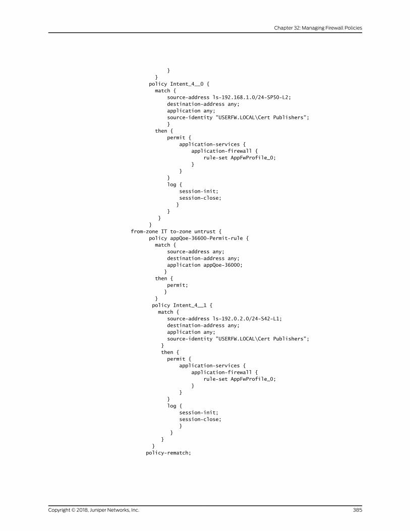
} } policy Intent_4__0 { match { source-address ls-192.168.1.0/24-SP50-L2; destination-address any; application any; source-identity "USERFW.LOCAL\Cert Publishers"; } then { permit { application-services { application-firewall { rule-set AppFwProfile_0; } } } log { session-init; session-close; } } } }from-zone IT to-zone untrust { policy appQoe-36600-Permit-rule { match { source-address any; destination-address any; application appQoe-36000; } then { permit; } } policy Intent_4__1 { match { source-address ls-192.0.2.0/24-S42-L1; destination-address any; application any; source-identity "USERFW.LOCAL\Cert Publishers"; } then { permit { application-services { application-firewall { rule-set AppFwProfile_0; } } } log { session-init; session-close; } } } } policy-rematch;
385Copyright © 2018, Juniper Networks, Inc.
Chapter 32: Managing Firewall Policies
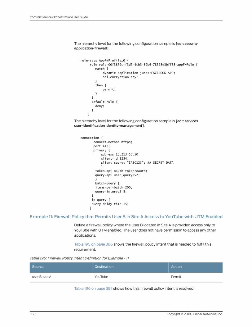
The hierarchy level for the following configuration sample is [edit securityapplication-firewall].
rule-sets AppFwProfile_0 { rule rule-00f3879c-f3d7-4cb3-89b6-78328e3bff38-appFwRule { match { dynamic-application junos:FACEBOOK-APP; ssl-encryption any; } then { permit; } } default-rule { deny; } }
The hierarchy level for the following configuration sample is [edit servicesuser-identification identity-management].
connection { connect-method https; port 443; primary { address 10.213.50.50; client-id 1234; client-secret "$ABC123"; ## SECRET-DATA } token-api oauth_token/oauth; query-api user_query/v2; } batch-query { items-per-batch 200; query-interval 5; } ip-query { query-delay-time 15; }
Example 11: Firewall Policy that Permits User B in Site A Access to YouTubewith UTM Enabled
Define a firewall policy where the User B located in Site A is provided access only to
YouTube with UTM enabled. The user does not have permission to access any other
applications.
Table 195 on page 386 shows the firewall policy intent that is needed to fulfil this
requirement:
Table 195: Firewall Policy Intent Definition for Example - 11
ActionDestinationSource
PermitYouTubeuser B, site A
Table 196 on page 387 shows how this firewall policy intent is resolved:
Copyright © 2018, Juniper Networks, Inc.386
Contrail Service Orchestration User Guide
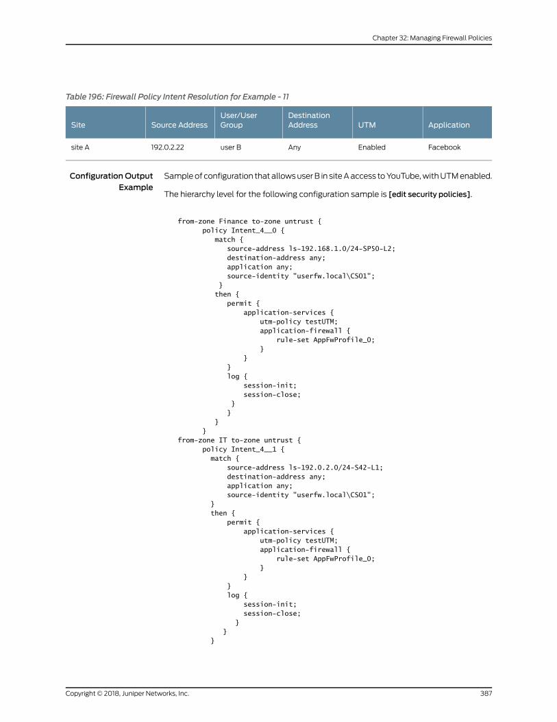
Table 196: Firewall Policy Intent Resolution for Example - 11
ApplicationUTMDestinationAddress
User/UserGroupSource AddressSite
FacebookEnabledAnyuser B192.0.2.22site A
Configuration OutputExample
Sampleof configuration thatallowsuserB in siteAaccess toYouTube,withUTMenabled.
The hierarchy level for the following configuration sample is [edit security policies].
from-zone Finance to-zone untrust { policy Intent_4__0 { match { source-address ls-192.168.1.0/24-SP50-L2; destination-address any; application any; source-identity "userfw.local\CSO1"; } then { permit { application-services { utm-policy testUTM; application-firewall { rule-set AppFwProfile_0; } } } log { session-init; session-close; } } } }from-zone IT to-zone untrust { policy Intent_4__1 { match { source-address ls-192.0.2.0/24-S42-L1; destination-address any; application any; source-identity "userfw.local\CSO1"; } then { permit { application-services { utm-policy testUTM; application-firewall { rule-set AppFwProfile_0; } } } log { session-init; session-close; } } }
387Copyright © 2018, Juniper Networks, Inc.
Chapter 32: Managing Firewall Policies
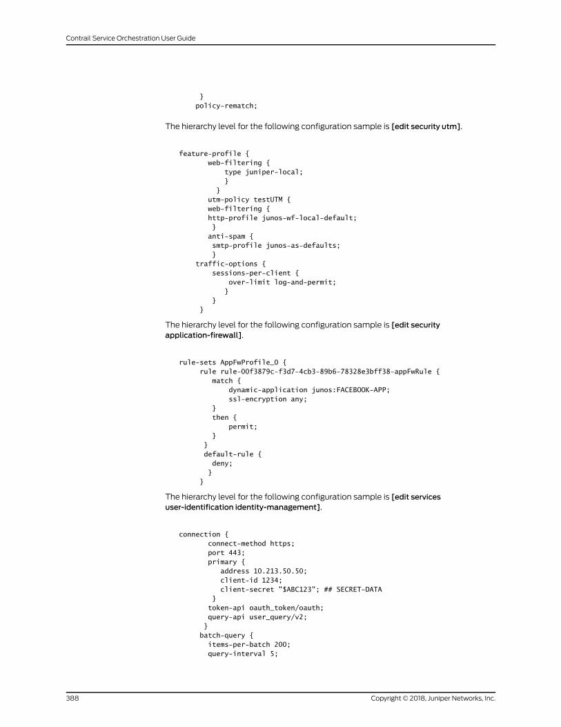
} policy-rematch;
The hierarchy level for the following configuration sample is [edit security utm].
feature-profile { web-filtering { type juniper-local; } } utm-policy testUTM { web-filtering { http-profile junos-wf-local-default; } anti-spam { smtp-profile junos-as-defaults; } traffic-options { sessions-per-client { over-limit log-and-permit; } } }
The hierarchy level for the following configuration sample is [edit securityapplication-firewall].
rule-sets AppFwProfile_0 { rule rule-00f3879c-f3d7-4cb3-89b6-78328e3bff38-appFwRule { match { dynamic-application junos:FACEBOOK-APP; ssl-encryption any; } then { permit; } } default-rule { deny; } }
The hierarchy level for the following configuration sample is [edit servicesuser-identification identity-management].
connection { connect-method https; port 443; primary { address 10.213.50.50; client-id 1234; client-secret "$ABC123"; ## SECRET-DATA } token-api oauth_token/oauth; query-api user_query/v2; } batch-query { items-per-batch 200; query-interval 5;
Copyright © 2018, Juniper Networks, Inc.388
Contrail Service Orchestration User Guide
} ip-query { query-delay-time 15; }
RelatedDocumentation
Firewall Policy Overview on page 343•
• Creating Firewall Policy Intents on page 345
Firewall Policy Schedules Overview
A schedule allows a policy to be active for a specified duration. If you want a policy to be
active during a scheduled time, youmust first create a schedule for that policy or link the
policy to an existing schedule. When a schedule timeout expires, the associated policy
is deactivated and all sessions associated with the policy are also timed out.
If a policy contains a reference to a schedule, that schedule determines when the policy
is active.When a policy is active, it can be used as a possiblematch for traffic. A schedule
lets you restrict access to, or remove a restriction from a resource, for a period of time.
A schedule uses the following guidelines:
• A schedule can havemultiple policies associated with it; however, a policy cannot be
associated with multiple schedules.
• A policy remains active as long as the schedule it refers to is also active.
A schedule can be active during a single time slot, as specified by a start date and time,
and a stop date and time.
• Aschedulecanbeactive forever (recurrent), butonlyas specifiedby thedaily schedule.
The schedule on a specific day (time slot) takes priority over the daily schedule.
• A scheduler can be active during a time slot, as specified by the weekday schedule.
• A scheduler be active within two different time slots (daily or for a specified duration).
RelatedDocumentation
About the Firewall Policy Schedules Page on page 389•
• Firewall Policy Examples on page 359
• Creating Schedules on page 390
• Editing, Cloning, and Deleting Schedules on page 392
About the Firewall Policy Schedules Page
To access this page, select Configuration > Firewall > Schedules.
The Firewall Policy Schedules page enables you to create, modify, clone, and delete
schedules. A schedule allows you to restrict access to a resource, or remove a restriction
to a resource, for a specified period of time.
389Copyright © 2018, Juniper Networks, Inc.
Chapter 32: Managing Firewall Policies
Tasks You Can Perform
You can perform the following tasks from this page:
• Create a firewall policy schedule. See “Creating Schedules” on page 390.
• Modify, clone, or delete a firewall policy schedule. See “Editing, Cloning, and Deleting
Schedules” on page 392.
• Viewtheconfiguredparametersof a schedule. Click thedetails icon thatappearswhen
youhover over the nameof an imageor clickMore>DetailedView. See “ViewingObject
Details” on page 241.
• Show or hide columns about the firewall policy schedule. See “Sorting Objects” on
page 241.
• Search for a specific firewall policy schedule. See “Searching for Text in anObject Data
Table” on page 242.
Field Descriptions
Table 197 on page 390 provides guidelines on using the fields on the Firewall Policy
Schedules page.
Table 197: Fields on the Firewall Policy Schedules Page
DescriptionField
Name of the schedule; maximum length is 63 characters.Name
Description for the schedule; maximum length is 900 characters.Description
The date and time fromwhen the schedule comes into effect.Start Date
The date and time fromwhen the schedule ends.End Date
The second date and time fromwhen the schedule comes into effect.Second Start Date
The second date and time fromwhen the schedule ends.Second End Date
RelatedDocumentation
Firewall Policy Schedules Overview on page 389•
• Firewall Policy Examples on page 359
• Creating Schedules on page 390
• Editing, Cloning, and Deleting Schedules on page 392
Creating Schedules
Use the Create Schedules page to create schedules. A schedule allows you to restrict
access to a resource, or remove a restriction to a resource, for a specified period of time.
Copyright © 2018, Juniper Networks, Inc.390
Contrail Service Orchestration User Guide
To configure a schedule:
1. Select Configuration > Firewall > Schedules.
The Firewall Policy Schedules page appears.
2. Click the add icon (+).
The Create Schedules page appears.
3. Complete the configuration of the schedule according to the guidelines provided in
Table 198 on page 391.
4. ClickOK to save the changes. If youwant todiscard your changes, clickCancel instead.
A new schedule is created. You can use this schedule to activate firewall policies for the
times and dates configured in your schedules.
Table 198 on page 391 provides guidelines on using the fields to create a schedule.
Table 198: Fields on the Create Schedules Page
DescriptionField
General Information
Required. Enter a unique name for the service. Itmust beginwith an alphanumeric characterand cannot exceed 63 characters. Dashes and underscores are allowed.
Name
Enter a description for your service. You should make this description as useful as possiblefor all administrators.
Description
Dates
SelectOngoing if you want your schedules to always be active.
Select Custom to configure two sets of start and end dates for a single schedule. For thefirst set, enter dates in the Start Date and End Date fields. Youmust enter the days inMM/DD/YYYY format.
For the second set of the schedule, enter the start date in the Second Start Date field andenter the end date in the Second End Date field.
Date Range
Times
Create a schedule to be active daily or for any specific times of the day.Time Ranges
391Copyright © 2018, Juniper Networks, Inc.
Chapter 32: Managing Firewall Policies
Table 198: Fields on the Create Schedules Page (continued)
DescriptionField
Select Daily to make the schedule applicable daily.
SelectCustom to enter specific daysand times.Clickonaspecific day to specify timeoptionsfor an entire day, to exclude a specific day, or to enter time ranges for the selected day. Youmust enter the time in HH:MM:SS format.
For example, if you click onMonday, you get a dialog box that allows you to specify whetheryou want the schedule to be active all day Monday, exclude Monday from the schedule, orhave the schedule be active at specific times.
Select Specify the same time for all days to enter a date and time that is applicable for alldays.
Daily Options
RelatedDocumentation
Firewall Policy Schedules Overview on page 389•
• About the Firewall Policy Schedules Page on page 389
• Firewall Policy Examples on page 359
• Editing, Cloning, and Deleting Schedules on page 392
Editing, Cloning, and Deleting Schedules
You can edit, clone, and delete schedules from the Firewall Policy Schedules page.
• Editing Schedules on page 392
• Cloning Schedules on page 393
• Deleting Schedules on page 393
Editing Schedules
Tomodify the parameters configured for a schedule:
1. Select Configuration > Firewall > Schedules.
The Firewall Policy Schedules page appears.
2. Select the schedule that you want to edit, and then click on the edit icon (pencil
symbol) on the right top corner of the table, or right-click and select Edit Schedule.
The Edit Schedules page appears, showing the same options as when creating a new
schedule.
3. Modify the parameters according to the guidelines provided in “Creating Schedules”
on page 390.
4. ClickOK to save the changes. If youwant todiscard your changes, clickCancel instead.
Copyright © 2018, Juniper Networks, Inc.392
Contrail Service Orchestration User Guide
If you clickOK, the modified schedule appears on the Firewall Policy Schedules page.
Cloning Schedules
To clone a schedule:
1. Select Configuration > Firewall Policy > Schedules.
The Firewall Policy Schedules page appears.
2. Right-click on the schedule that youwant to clone and then clickClone, or selectMore
> Clone.
TheCloneSchedulespageappearswitheditable fields.Youcanmodify theparameters
according to the guidelines provided in “Creating Schedules” on page 390.
3. ClickOK to save the changes. If youwant todiscard your changes, clickCancel instead.
If you clickOK, the cloned schedule appears under the scheduled it is cloned from, in the
Firewall Policy Schedules.
Deleting Schedules
To delete a schedule:
1. Select Configuration > Firewall Policy > Schedules.
The Firewall Policy Schedules page appears.
2. Select the schedule you want to delete and then click the delete icon (X) .
An alert message appears, verifying that you want to delete the schedule.
3. Click Yes to delete the selection. If you do not want to delete, click Cancel instead.
If you click Yes, the selected schedule is deleted.
RelatedDocumentation
• Firewall Policy Schedules Overview on page 389
• About the Firewall Policy Schedules Page on page 389
• Creating Schedules on page 390
• Firewall Policy Examples on page 359
393Copyright © 2018, Juniper Networks, Inc.
Chapter 32: Managing Firewall Policies

Copyright © 2018, Juniper Networks, Inc.394
Contrail Service Orchestration User Guide
CHAPTER 33
Unified Threat Management
• UTMOverview on page 396
• Configuring UTM Settings on page 398
• About the UTM Profiles Page on page 399
• Creating UTM Profiles on page 401
• Editing, Cloning, and Deleting UTM Profiles on page 403
• About theWeb Filtering Profiles Page on page 405
• CreatingWeb Filtering Profiles on page 407
• Editing, Cloning, and DeletingWeb Filtering Profiles on page 411
• About the Antivirus Profiles Page on page 413
• Creating Antivirus Profiles on page 414
• Editing, Cloning, and Deleting Antivirus Profiles on page 416
• About the Antispam Profiles Page on page 418
• Creating Antispam Profiles on page 419
• Editing, Cloning, and Deleting Antispam Profiles on page 421
• About the Content Filtering Profiles Page on page 422
• Creating Content Filtering Profiles on page 424
• Editing, Cloning, and Deleting Content Filtering Profiles on page 427
• About the URL Patterns Page on page 429
• Creating URL Patterns on page 429
• Editing, Cloning, and Deleting URL Patterns on page 431
• About the URL Categories Page on page 432
• Creating URL Categories on page 433
• Editing, Cloning, and Deleting URL Categories on page 434
395Copyright © 2018, Juniper Networks, Inc.
UTMOverview
Unified threatmanagement (UTM) isa termused todescribe theconsolidationof several
security features to protect against multiple threat types. The advantage of UTM is a
streamlined installation andmanagement of multiple security capabilities.
The following security features are provided as part of the UTM solution:
• Antispam—This feature examines transmittedmessages to identify e-mail spam.
E-mail spam consists of unwantedmessages usually sent by commercial, malicious,
or fraudulent entities.When thedevicedetectsane-mailmessagedeemed tobespam,
it either drops the message or tags the message header or subject field with a
preprogrammed string. The antispam feature uses a constantly updated Spamhaus
Block List (SBL). Sophos updates andmaintains the IP-based SBL.
• Full file-based antivirus—A virus is an executable code that infects or attaches itself
to other executable code to reproduce itself. Somemalicious viruses erase files or lock
up systems.Other virusesmerely infect files and overwhelm the target host or network
with bogus data. The full file-based antivirus feature provides file-based scanning on
specific application layer traffic, checking for virusesagainst a virus signaturedatabase.
The antivirus feature collects the received data packets until it has reconstructed the
original application content, such as an e-mail file attachment, and then scans this
content.
• Express antivirus—Express antivirus scanning is offered as a less CPU-intensive
alternative to the full file-basedantivirus feature. Theexpress antivirus feature is similar
to theantivirus feature in that it scans specific application layer traffic for virusesagainst
a virus signature database. However, unlike full antivirus, express antivirus does not
reconstruct theoriginal application content. Rather, it just sends (streams) the received
data packets, as is, to the scan engine. With express antivirus, the virus scanning is
executed by a hardware pattern-matching engine. This improves performance while
scanning is occurring, but the level of security provided is lessened. Juniper Networks
provides the scan engine.
• Content filtering—Content filtering blocks or permits certain types of traffic based on
the MIME type, file extension, protocol command, and embedded object type.
• Webfiltering—Web filteringenables you tomanage Internet usagebypreventingaccess
to inappropriateWeb content. The following types ofWeb filtering solutions are
available:
• IntegratedWeb filtering—Blocks or permits Web access after the device identifies
the category for a URL either from user-defined categories or from a category server
(Websense provides the SurfControl Content Portal Authority (CPA) server).
• Redirect Web filtering—Intercepts HTTP requests and forwards the server URL to
anexternalURL filtering server todeterminewhether toblockorpermit the requested
Web access. Websense provides the URL filtering server.
• UTM Licensing on page 397
• UTM Components on page 397
Copyright © 2018, Juniper Networks, Inc.396
Contrail Service Orchestration User Guide
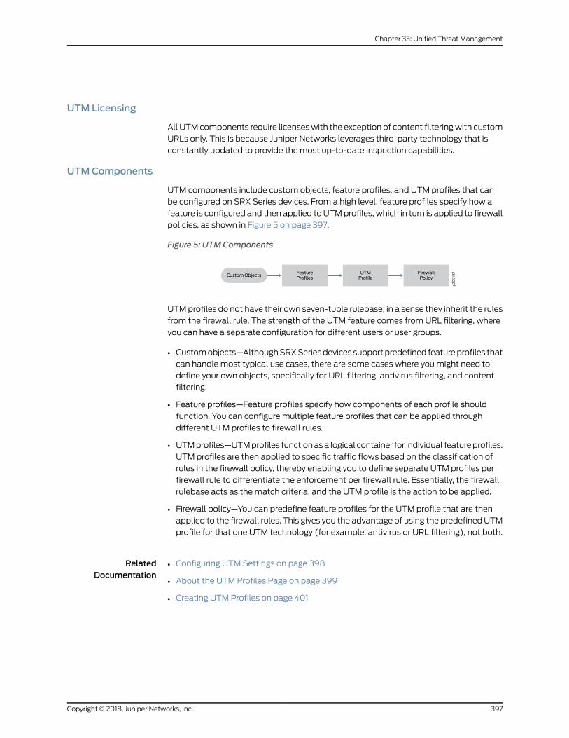
UTM Licensing
All UTMcomponents require licenseswith the exception of content filteringwith custom
URLs only. This is because Juniper Networks leverages third-party technology that is
constantly updated to provide the most up-to-date inspection capabilities.
UTMComponents
UTM components include custom objects, feature profiles, and UTM profiles that can
be configured on SRX Series devices. From a high level, feature profiles specify how a
feature is configured and then applied to UTMprofiles, which in turn is applied to firewall
policies, as shown in Figure 5 on page 397.
Figure 5: UTMComponents
g200187UTM
ProfileFeatureProfiles
CustomObjectsFirewallPolicy
UTMprofiles do not have their own seven-tuple rulebase; in a sense they inherit the rules
from the firewall rule. The strength of the UTM feature comes from URL filtering, where
you can have a separate configuration for different users or user groups.
• Customobjects—AlthoughSRXSeriesdevices support predefined featureprofiles that
can handle most typical use cases, there are some cases where youmight need to
define your own objects, specifically for URL filtering, antivirus filtering, and content
filtering.
• Feature profiles—Feature profiles specify how components of each profile should
function. You can configure multiple feature profiles that can be applied through
different UTM profiles to firewall rules.
• UTMprofiles—UTMprofiles functionasa logical container for individual featureprofiles.
UTM profiles are then applied to specific traffic flows based on the classification of
rules in the firewall policy, thereby enabling you to define separate UTM profiles per
firewall rule to differentiate the enforcement per firewall rule. Essentially, the firewall
rulebase acts as the match criteria, and the UTM profile is the action to be applied.
• Firewall policy—You can predefine feature profiles for the UTM profile that are then
applied to the firewall rules. This gives you the advantage of using the predefinedUTM
profile for that one UTM technology (for example, antivirus or URL filtering), not both.
RelatedDocumentation
Configuring UTM Settings on page 398•
• About the UTM Profiles Page on page 399
• Creating UTM Profiles on page 401
397Copyright © 2018, Juniper Networks, Inc.
Chapter 33: Unified Threat Management
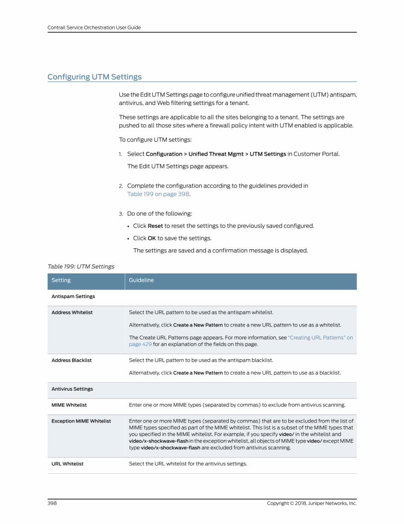
Configuring UTMSettings
Use theEditUTMSettingspage toconfigureunified threatmanagement (UTM)antispam,
antivirus, andWeb filtering settings for a tenant.
These settings are applicable to all the sites belonging to a tenant. The settings are
pushed to all those sites where a firewall policy intent with UTM enabled is applicable.
To configure UTM settings:
1. Select Configuration > Unified Threat Mgmt > UTMSettings in Customer Portal.
The Edit UTM Settings page appears.
2. Complete the configuration according to the guidelines provided in
Table 199 on page 398.
3. Do one of the following:
• Click Reset to reset the settings to the previously saved configured.
• ClickOK to save the settings.
The settings are saved and a confirmation message is displayed.
Table 199: UTM Settings
GuidelineSetting
AntispamSettings
Select the URL pattern to be used as the antispamwhitelist.
Alternatively, click Create a NewPattern to create a new URL pattern to use as a whitelist.
The Create URL Patterns page appears. For more information, see “Creating URL Patterns” onpage 429 for an explanation of the fields on this page.
AddressWhitelist
Select the URL pattern to be used as the antispam blacklist.
Alternatively, click Create a NewPattern to create a new URL pattern to use as a blacklist.
Address Blacklist
Antivirus Settings
Enter one or more MIME types (separated by commas) to exclude from antivirus scanning.MIMEWhitelist
Enter one or more MIME types (separated by commas) that are to be excluded from the list ofMIME types specified as part of the MIME whitelist. This list is a subset of the MIME types thatyou specified in the MIME whitelist. For example, if you specify video/ in the whitelist andvideo/x-shockwave-flash in theexceptionwhitelist, all objectsofMIMEtypevideo/exceptMIMEtype video/x-shockwave-flash are excluded from antivirus scanning.
ExceptionMIMEWhitelist
Select the URL whitelist for the antivirus settings.URLWhitelist
Copyright © 2018, Juniper Networks, Inc.398
Contrail Service Orchestration User Guide
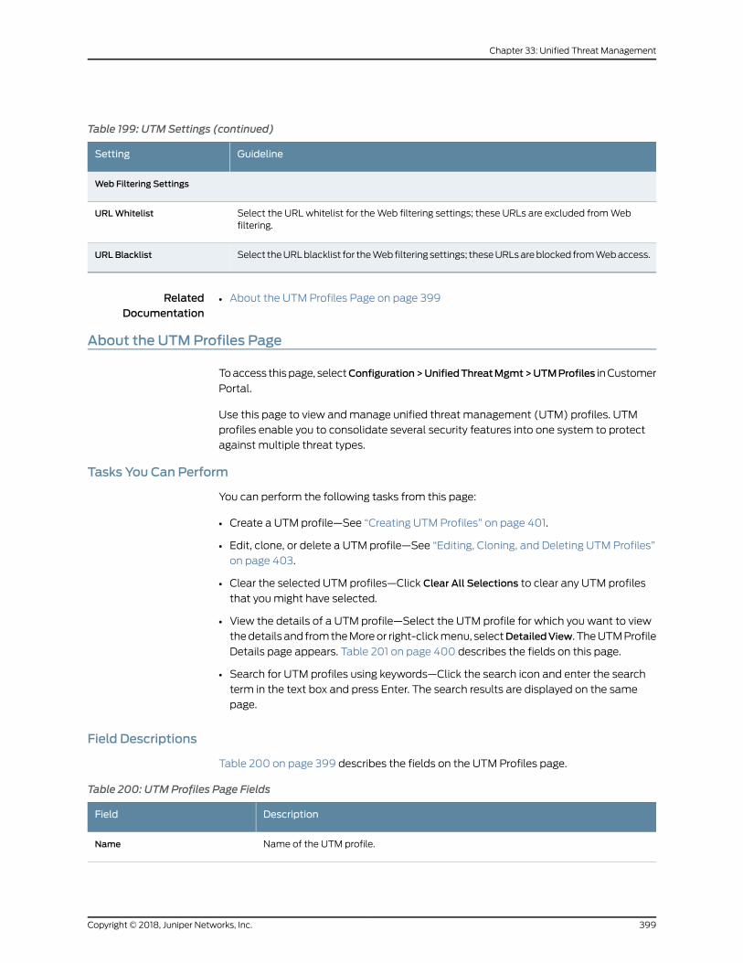
Table 199: UTM Settings (continued)
GuidelineSetting
Web Filtering Settings
Select the URL whitelist for theWeb filtering settings; these URLs are excluded fromWebfiltering.
URLWhitelist
Select theURLblacklist for theWeb filtering settings; theseURLsareblocked fromWebaccess.URL Blacklist
RelatedDocumentation
About the UTM Profiles Page on page 399•
About the UTMProfiles Page
Toaccess thispage, selectConfiguration>UnifiedThreatMgmt>UTMProfiles inCustomer
Portal.
Use this page to view andmanage unified threat management (UTM) profiles. UTM
profiles enable you to consolidate several security features into one system to protect
against multiple threat types.
Tasks You Can Perform
You can perform the following tasks from this page:
• Create a UTM profile—See “Creating UTM Profiles” on page 401.
• Edit, clone, or delete a UTM profile—See “Editing, Cloning, and Deleting UTM Profiles”
on page 403.
• Clear the selected UTM profiles—Click Clear All Selections to clear any UTM profiles
that youmight have selected.
• View the details of a UTM profile—Select the UTM profile for which you want to view
thedetails and fromtheMoreor right-clickmenu, selectDetailedView. TheUTMProfile
Details page appears. Table 201 on page 400 describes the fields on this page.
• Search for UTM profiles using keywords—Click the search icon and enter the search
term in the text box and press Enter. The search results are displayed on the same
page.
Field Descriptions
Table 200 on page 399 describes the fields on the UTM Profiles page.
Table 200: UTMProfiles Page Fields
DescriptionField
Name of the UTM profile.Name
399Copyright © 2018, Juniper Networks, Inc.
Chapter 33: Unified Threat Management
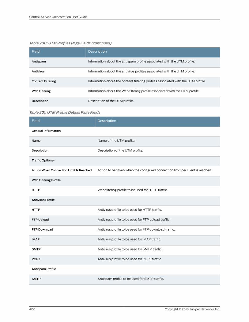
Table 200: UTMProfiles Page Fields (continued)
DescriptionField
Information about the antispam profile associated with the UTM profile.Antispam
Information about the antivirus profiles associated with the UTM profile.Antivirus
Information about the content filtering profiles associated with the UTM profile.Content Filtering
Information about theWeb filtering profile associated with the UTM profile.Web Filtering
Description of the UTM profile.Description
Table 201: UTM Profile Details Page Fields
DescriptionField
General Information
Name of the UTM profile.Name
Description of the UTM profile.Description
Traffic Options-
Action to be taken when the configured connection limit per client is reached.ActionWhen Connection Limit Is Reached
Web Filtering Profile
Web filtering profile to be used for HTTP traffic.HTTP
Antivirus Profile
Antivirus profile to be used for HTTP traffic.HTTP
Antivirus profile to be used for FTP upload traffic.FTP Upload
Antivirus profile to be used for FTP download traffic.FTP Download
Antivirus profile to be used for IMAP traffic.IMAP
Antivirus profile to be used for SMTP traffic.SMTP
Antivirus profile to be used for POP3 traffic.POP3
AntispamProfile
Antispam profile to be used for SMTP traffic.SMTP
Copyright © 2018, Juniper Networks, Inc.400
Contrail Service Orchestration User Guide
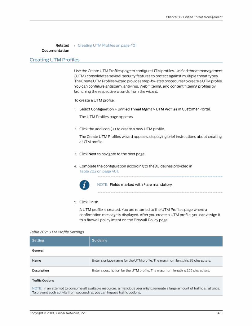
RelatedDocumentation
Creating UTM Profiles on page 401•
Creating UTMProfiles
Use theCreateUTMProfiles page to configureUTMprofiles. Unified threatmanagement
(UTM) consolidates several security features to protect against multiple threat types.
TheCreateUTMProfileswizardprovides step-by-stepprocedures tocreateaUTMprofile.
You can configure antispam, antivirus, Web filtering, and content filtering profiles by
launching the respective wizards from the wizard.
To create a UTM profile:
1. Select Configuration > Unified Threat Mgmt > UTMProfiles in Customer Portal.
The UTM Profiles page appears.
2. Click the add icon (+) to create a new UTM profile.
The Create UTM Profiles wizard appears, displaying brief instructions about creating
a UTM profile.
3. Click Next to navigate to the next page.
4. Complete the configuration according to the guidelines provided in
Table 202 on page 401.
NOTE: Fieldsmarked with * aremandatory.
5. Click Finish.
A UTM profile is created. You are returned to the UTM Profiles page where a
confirmation message is displayed. After you create a UTM profile, you can assign it
to a firewall policy intent on the Firewall Policy page.
Table 202: UTM Profile Settings
GuidelineSetting
General
Enter a unique name for the UTM profile. Themaximum length is 29 characters.Name
Enter a description for the UTM profile. Themaximum length is 255 characters.Description
Traffic Options
NOTE: In an attempt to consume all available resources, a malicious user might generate a large amount of traffic all at once.To prevent such activity from succeeding, you can impose traffic options.
401Copyright © 2018, Juniper Networks, Inc.
Chapter 33: Unified Threat Management
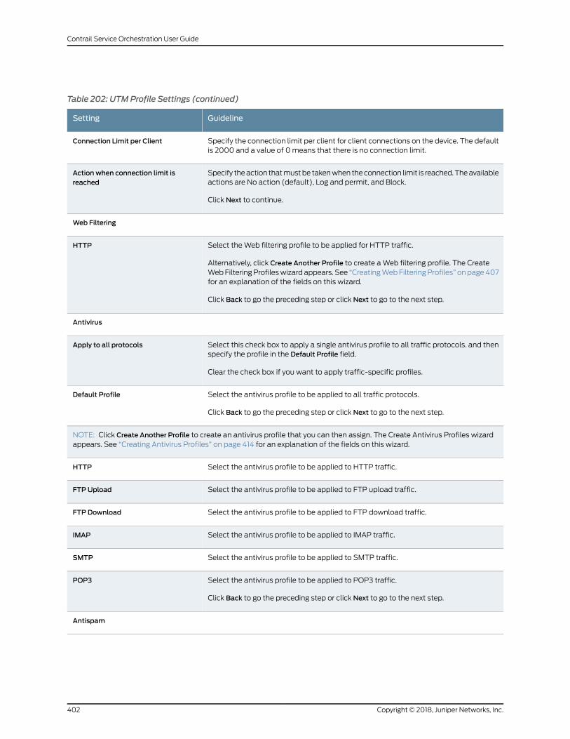
Table 202: UTM Profile Settings (continued)
GuidelineSetting
Specify the connection limit per client for client connections on the device. The defaultis 2000 and a value of 0means that there is no connection limit.
Connection Limit per Client
Specify theaction thatmustbe takenwhen theconnection limit is reached.Theavailableactions are No action (default), Log and permit, and Block.
Click Next to continue.
Action when connection limit isreached
Web Filtering
Select theWeb filtering profile to be applied for HTTP traffic.
Alternatively, click Create Another Profile to create aWeb filtering profile. The CreateWebFilteringProfileswizard appears. See “CreatingWebFilteringProfiles” onpage407for an explanation of the fields on this wizard.
Click Back to go the preceding step or click Next to go to the next step.
HTTP
Antivirus
Select this check box to apply a single antivirus profile to all traffic protocols. and thenspecify the profile in the Default Profile field.
Clear the check box if you want to apply traffic-specific profiles.
Apply to all protocols
Select the antivirus profile to be applied to all traffic protocols.
Click Back to go the preceding step or click Next to go to the next step.
Default Profile
NOTE: Click Create Another Profile to create an antivirus profile that you can then assign. The Create Antivirus Profiles wizardappears. See “Creating Antivirus Profiles” on page 414 for an explanation of the fields on this wizard.
Select the antivirus profile to be applied to HTTP traffic.HTTP
Select the antivirus profile to be applied to FTP upload traffic.FTP Upload
Select the antivirus profile to be applied to FTP download traffic.FTP Download
Select the antivirus profile to be applied to IMAP traffic.IMAP
Select the antivirus profile to be applied to SMTP traffic.SMTP
Select the antivirus profile to be applied to POP3 traffic.
Click Back to go the preceding step or click Next to go to the next step.
POP3
Antispam
Copyright © 2018, Juniper Networks, Inc.402
Contrail Service Orchestration User Guide
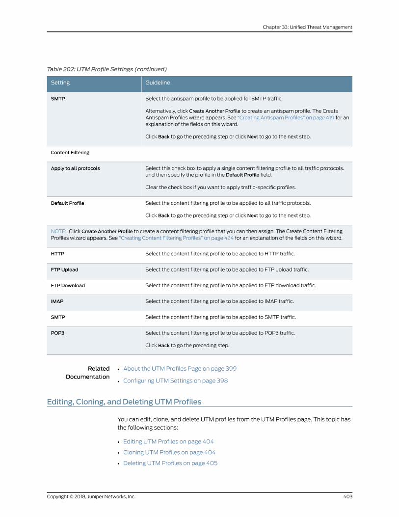
Table 202: UTM Profile Settings (continued)
GuidelineSetting
Select the antispam profile to be applied for SMTP traffic.
Alternatively, click Create Another Profile to create an antispam profile. The CreateAntispamProfiles wizard appears. See “Creating AntispamProfiles” on page 419 for anexplanation of the fields on this wizard.
Click Back to go the preceding step or click Next to go to the next step.
SMTP
Content Filtering
Select this check box to apply a single content filtering profile to all traffic protocols.and then specify the profile in the Default Profile field.
Clear the check box if you want to apply traffic-specific profiles.
Apply to all protocols
Select the content filtering profile to be applied to all traffic protocols.
Click Back to go the preceding step or click Next to go to the next step.
Default Profile
NOTE: Click Create Another Profile to create a content filtering profile that you can then assign. The Create Content FilteringProfiles wizard appears. See “Creating Content Filtering Profiles” on page 424 for an explanation of the fields on this wizard.
Select the content filtering profile to be applied to HTTP traffic.HTTP
Select the content filtering profile to be applied to FTP upload traffic.FTP Upload
Select the content filtering profile to be applied to FTP download traffic.FTP Download
Select the content filtering profile to be applied to IMAP traffic.IMAP
Select the content filtering profile to be applied to SMTP traffic.SMTP
Select the content filtering profile to be applied to POP3 traffic.
Click Back to go the preceding step.
POP3
RelatedDocumentation
About the UTM Profiles Page on page 399•
• Configuring UTM Settings on page 398
Editing, Cloning, and Deleting UTMProfiles
You can edit, clone, and delete UTM profiles from the UTM Profiles page. This topic has
the following sections:
• Editing UTM Profiles on page 404
• Cloning UTM Profiles on page 404
• Deleting UTM Profiles on page 405
403Copyright © 2018, Juniper Networks, Inc.
Chapter 33: Unified Threat Management
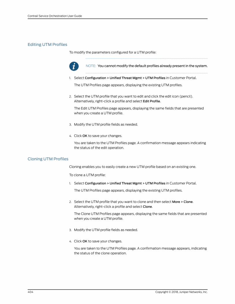
Editing UTMProfiles
Tomodify the parameters configured for a UTM profile:
NOTE: You cannotmodify the default profiles already present in the system.
1. Select Configuration > Unified Threat Mgmt > UTMProfiles in Customer Portal.
The UTM Profiles page appears, displaying the existing UTM profiles.
2. Select the UTM profile that you want to edit and click the edit icon (pencil).
Alternatively, right-click a profile and select Edit Profile.
The Edit UTM Profiles page appears, displaying the same fields that are presented
when you create a UTM profile.
3. Modify the UTM profile fields as needed.
4. ClickOK to save your changes.
You are taken to the UTM Profiles page. A confirmation message appears indicating
the status of the edit operation.
Cloning UTMProfiles
Cloning enables you to easily create a new UTM profile based on an existing one.
To clone a UTM profile:
1. Select Configuration > Unified Threat Mgmt > UTMProfiles in Customer Portal.
The UTM Profiles page appears, displaying the existing UTM profiles.
2. Select the UTM profile that you want to clone and then selectMore > Clone.
Alternatively, right-click a profile and select Clone.
The Clone UTM Profiles page appears, displaying the same fields that are presented
when you create a UTM profile.
3. Modify the UTM profile fields as needed.
4. ClickOK to save your changes.
You are taken to the UTM Profiles page. A confirmation message appears, indicating
the status of the clone operation.
Copyright © 2018, Juniper Networks, Inc.404
Contrail Service Orchestration User Guide
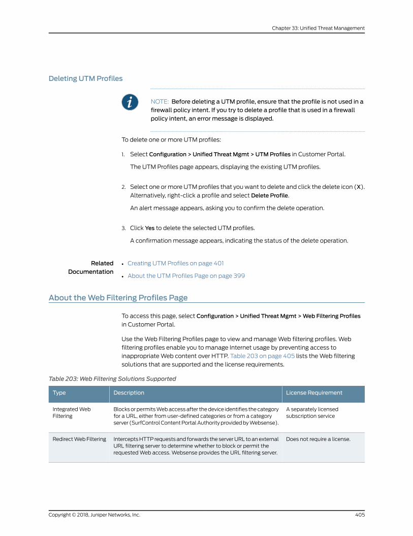
Deleting UTMProfiles
NOTE: Before deleting a UTM profile, ensure that the profile is not used in afirewall policy intent. If you try to delete a profile that is used in a firewallpolicy intent, an error message is displayed.
To delete one or more UTM profiles:
1. Select Configuration > Unified Threat Mgmt > UTMProfiles in Customer Portal.
The UTM Profiles page appears, displaying the existing UTM profiles.
2. Select one ormore UTMprofiles that youwant to delete and click the delete icon (X).
Alternatively, right-click a profile and select Delete Profile.
An alert message appears, asking you to confirm the delete operation.
3. Click Yes to delete the selected UTM profiles.
A confirmation message appears, indicating the status of the delete operation.
RelatedDocumentation
Creating UTM Profiles on page 401•
• About the UTM Profiles Page on page 399
About theWeb Filtering Profiles Page
To access this page, select Configuration > Unified Threat Mgmt >Web Filtering Profiles
in Customer Portal.
Use theWeb Filtering Profiles page to view andmanageWeb filtering profiles. Web
filtering profiles enable you to manage Internet usage by preventing access to
inappropriateWeb content over HTTP. Table 203 on page 405 lists theWeb filtering
solutions that are supported and the license requirements.
Table 203:Web Filtering Solutions Supported
License RequirementDescriptionType
A separately licensedsubscription service
Blocksor permitsWebaccessafter thedevice identifies thecategoryfor a URL, either from user-defined categories or from a categoryserver (SurfControlContentPortalAuthorityprovidedbyWebsense).
IntegratedWebFiltering
Does not require a license.InterceptsHTTP requestsand forwards the serverURL toanexternalURL filtering server to determine whether to block or permit therequestedWeb access. Websense provides the URL filtering server.
RedirectWebFiltering
405Copyright © 2018, Juniper Networks, Inc.
Chapter 33: Unified Threat Management
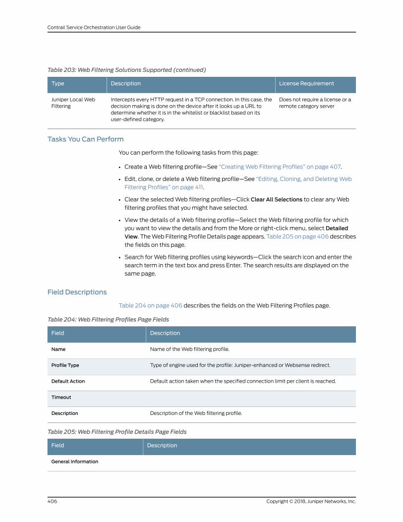
Table 203:Web Filtering Solutions Supported (continued)
License RequirementDescriptionType
Does not require a license or aremote category server
Intercepts every HTTP request in a TCP connection. In this case, thedecision making is done on the device after it looks up a URL todetermine whether it is in the whitelist or blacklist based on itsuser-defined category.
Juniper Local WebFiltering
Tasks You Can Perform
You can perform the following tasks from this page:
• Create aWeb filtering profile—See “CreatingWeb Filtering Profiles” on page 407.
• Edit, clone, or delete aWeb filtering profile—See “Editing, Cloning, and DeletingWeb
Filtering Profiles” on page 411.
• Clear the selectedWeb filtering profiles—Click Clear All Selections to clear anyWeb
filtering profiles that youmight have selected.
• View the details of aWeb filtering profile—Select theWeb filtering profile for which
you want to view the details and from the More or right-click menu, select Detailed
View. TheWebFiltering Profile Details page appears. Table 205onpage406describes
the fields on this page.
• Search for Web filtering profiles using keywords—Click the search icon and enter the
search term in the text box and press Enter. The search results are displayed on the
same page.
Field Descriptions
Table 204 on page 406 describes the fields on theWeb Filtering Profiles page.
Table 204:Web Filtering Profiles Page Fields
DescriptionField
Name of theWeb filtering profile.Name
Type of engine used for the profile: Juniper-enhanced orWebsense redirect.Profile Type
Default action taken when the specified connection limit per client is reached.Default Action
Timeout
Description of theWeb filtering profile.Description
Table 205:Web Filtering Profile Details Page Fields
DescriptionField
General Information
Copyright © 2018, Juniper Networks, Inc.406
Contrail Service Orchestration User Guide
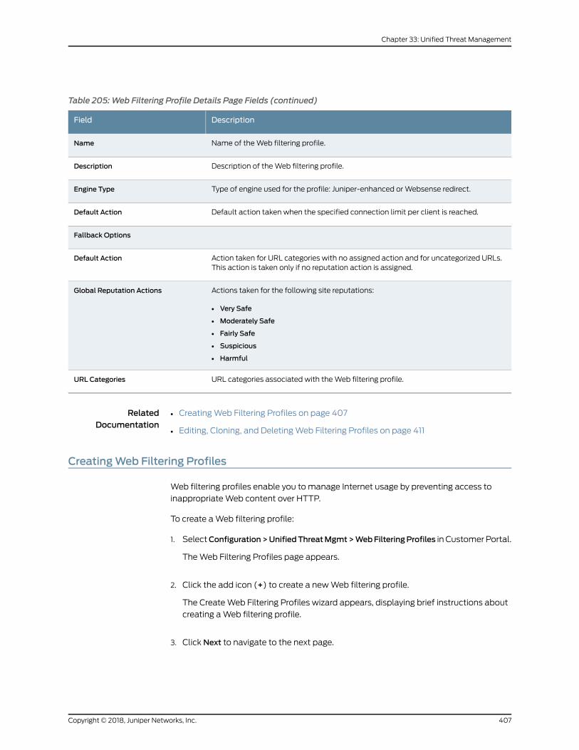
Table 205:Web Filtering Profile Details Page Fields (continued)
DescriptionField
Name of theWeb filtering profile.Name
Description of theWeb filtering profile.Description
Type of engine used for the profile: Juniper-enhanced orWebsense redirect.Engine Type
Default action taken when the specified connection limit per client is reached.Default Action
Fallback Options
Action taken for URL categories with no assigned action and for uncategorized URLs.This action is taken only if no reputation action is assigned.
Default Action
Actions taken for the following site reputations:
• Very Safe
• Moderately Safe
• Fairly Safe
• Suspicious
• Harmful
Global Reputation Actions
URL categories associated with theWeb filtering profile.URL Categories
RelatedDocumentation
CreatingWeb Filtering Profiles on page 407•
• Editing, Cloning, and DeletingWeb Filtering Profiles on page 411
CreatingWeb Filtering Profiles
Web filtering profiles enable you to manage Internet usage by preventing access to
inappropriateWeb content over HTTP.
To create aWeb filtering profile:
1. SelectConfiguration>UnifiedThreatMgmt>WebFilteringProfiles in Customer Portal.
TheWeb Filtering Profiles page appears.
2. Click the add icon (+) to create a newWeb filtering profile.
The CreateWeb Filtering Profiles wizard appears, displaying brief instructions about
creating aWeb filtering profile.
3. Click Next to navigate to the next page.
407Copyright © 2018, Juniper Networks, Inc.
Chapter 33: Unified Threat Management
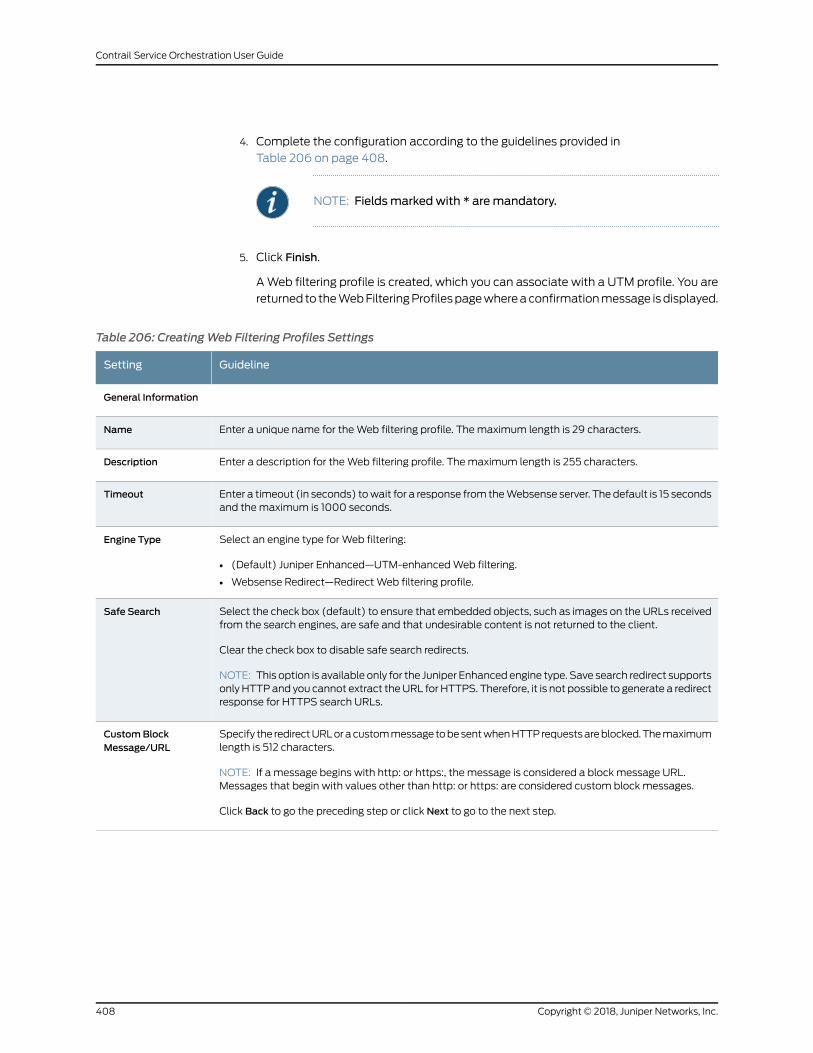
4. Complete the configuration according to the guidelines provided in
Table 206 on page 408.
NOTE: Fieldsmarked with * aremandatory.
5. Click Finish.
AWeb filtering profile is created, which you can associate with a UTM profile. You are
returned to theWebFilteringProfilespagewhereaconfirmationmessage isdisplayed.
Table 206: CreatingWeb Filtering Profiles Settings
GuidelineSetting
General Information
Enter a unique name for theWeb filtering profile. Themaximum length is 29 characters.Name
Enter a description for theWeb filtering profile. Themaximum length is 255 characters.Description
Enter a timeout (in seconds) towait for a response from theWebsense server. The default is 15 secondsand themaximum is 1000 seconds.
Timeout
Select an engine type for Web filtering:
• (Default) Juniper Enhanced—UTM-enhancedWeb filtering.
• Websense Redirect—Redirect Web filtering profile.
Engine Type
Select the check box (default) to ensure that embedded objects, such as images on the URLs receivedfrom the search engines, are safe and that undesirable content is not returned to the client.
Clear the check box to disable safe search redirects.
NOTE: This option is available only for the Juniper Enhanced engine type. Save search redirect supportsonly HTTPand you cannot extract theURL for HTTPS. Therefore, it is not possible to generate a redirectresponse for HTTPS search URLs.
Safe Search
Specify the redirectURLoracustommessage tobesentwhenHTTPrequestsareblocked.Themaximumlength is 512 characters.
NOTE: If a message begins with http: or https:, the message is considered a block message URL.Messages that begin with values other than http: or https: are considered custom block messages.
Click Back to go the preceding step or click Next to go to the next step.
CustomBlockMessage/URL
Copyright © 2018, Juniper Networks, Inc.408
Contrail Service Orchestration User Guide
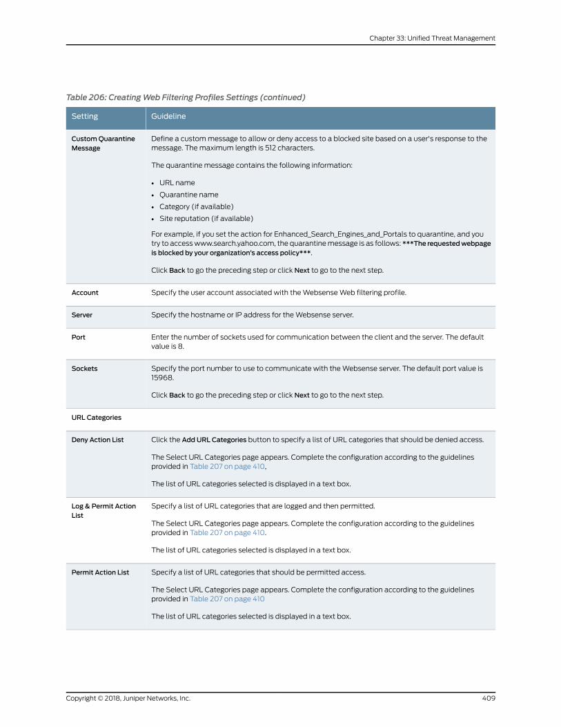
Table 206: CreatingWeb Filtering Profiles Settings (continued)
GuidelineSetting
Define a custommessage to allow or deny access to a blocked site based on a user's response to themessage. Themaximum length is 512 characters.
The quarantine message contains the following information:
• URL name
• Quarantine name
• Category (if available)
• Site reputation (if available)
For example, if you set the action for Enhanced_Search_Engines_and_Portals to quarantine, and youtry to accesswww.search.yahoo.com, the quarantinemessage is as follows: ***The requestedwebpageis blocked by your organization’s access policy***.
Click Back to go the preceding step or click Next to go to the next step.
CustomQuarantineMessage
Specify the user account associated with theWebsenseWeb filtering profile.Account
Specify the hostname or IP address for theWebsense server.Server
Enter the number of sockets used for communication between the client and the server. The defaultvalue is 8.
Port
Specify the port number to use to communicate with theWebsense server. The default port value is15968.
Click Back to go the preceding step or click Next to go to the next step.
Sockets
URL Categories
Click the Add URL Categories button to specify a list of URL categories that should be denied access.
The Select URL Categories page appears. Complete the configuration according to the guidelinesprovided in Table 207 on page 410,
The list of URL categories selected is displayed in a text box.
Deny Action List
Specify a list of URL categories that are logged and then permitted.
The Select URL Categories page appears. Complete the configuration according to the guidelinesprovided in Table 207 on page 410.
The list of URL categories selected is displayed in a text box.
Log & Permit ActionList
Specify a list of URL categories that should be permitted access.
The Select URL Categories page appears. Complete the configuration according to the guidelinesprovided in Table 207 on page 410
The list of URL categories selected is displayed in a text box.
Permit Action List
409Copyright © 2018, Juniper Networks, Inc.
Chapter 33: Unified Threat Management
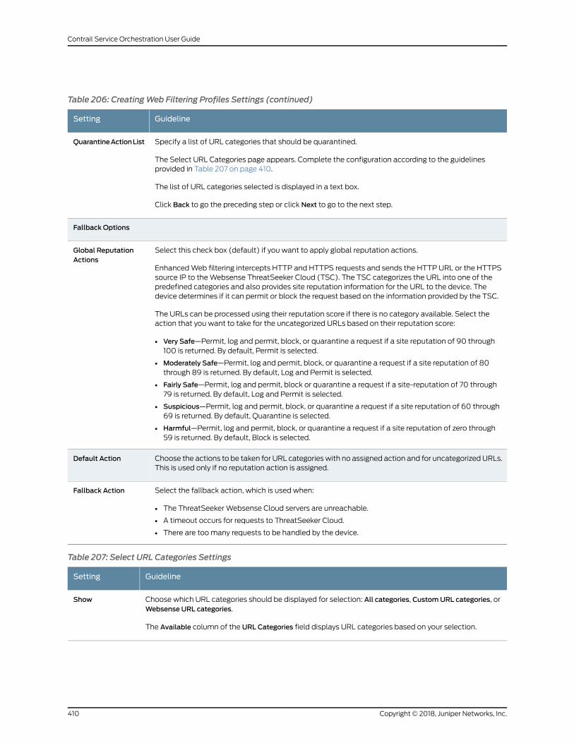
Table 206: CreatingWeb Filtering Profiles Settings (continued)
GuidelineSetting
Specify a list of URL categories that should be quarantined.
The Select URL Categories page appears. Complete the configuration according to the guidelinesprovided in Table 207 on page 410.
The list of URL categories selected is displayed in a text box.
Click Back to go the preceding step or click Next to go to the next step.
QuarantineActionList
Fallback Options
Select this check box (default) if you want to apply global reputation actions.
EnhancedWeb filtering intercepts HTTP and HTTPS requests and sends the HTTP URL or the HTTPSsource IP to theWebsense ThreatSeeker Cloud (TSC). The TSC categorizes the URL into one of thepredefined categories and also provides site reputation information for the URL to the device. Thedevice determines if it can permit or block the request based on the information provided by the TSC.
The URLs can be processed using their reputation score if there is no category available. Select theaction that you want to take for the uncategorized URLs based on their reputation score:
• Very Safe—Permit, log and permit, block, or quarantine a request if a site reputation of 90 through100 is returned. By default, Permit is selected.
• Moderately Safe—Permit, log and permit, block, or quarantine a request if a site reputation of 80through 89 is returned. By default, Log and Permit is selected.
• Fairly Safe—Permit, log and permit, block or quarantine a request if a site-reputation of 70 through79 is returned. By default, Log and Permit is selected.
• Suspicious—Permit, log and permit, block, or quarantine a request if a site reputation of 60 through69 is returned. By default, Quarantine is selected.
• Harmful—Permit, log and permit, block, or quarantine a request if a site reputation of zero through59 is returned. By default, Block is selected.
Global ReputationActions
Choose the actions to be taken for URL categorieswith no assigned action and for uncategorizedURLs.This is used only if no reputation action is assigned.
Default Action
Select the fallback action, which is used when:
• The ThreatSeeker Websense Cloud servers are unreachable.
• A timeout occurs for requests to ThreatSeeker Cloud.
• There are toomany requests to be handled by the device.
Fallback Action
Table 207: Select URL Categories Settings
GuidelineSetting
Choose which URL categories should be displayed for selection: All categories, CustomURL categories, orWebsense URL categories.
The Available column of the URL Categories field displays URL categories based on your selection.
Show
Copyright © 2018, Juniper Networks, Inc.410
Contrail Service Orchestration User Guide
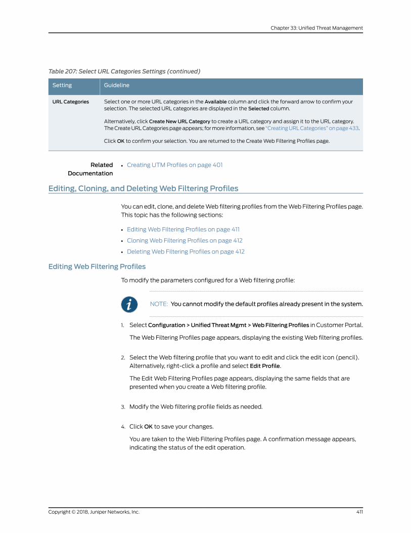
Table 207: Select URL Categories Settings (continued)
GuidelineSetting
Select one or more URL categories in the Available column and click the forward arrow to confirm yourselection. The selected URL categories are displayed in the Selected column.
Alternatively, click Create NewURL Category to create a URL category and assign it to the URL category.TheCreateURLCategoriespageappears; formore information, see “CreatingURLCategories” onpage433.
ClickOK to confirm your selection. You are returned to the CreateWeb Filtering Profiles page.
URL Categories
RelatedDocumentation
Creating UTM Profiles on page 401•
Editing, Cloning, and DeletingWeb Filtering Profiles
You can edit, clone, and deleteWeb filtering profiles from theWeb Filtering Profiles page.
This topic has the following sections:
• EditingWeb Filtering Profiles on page 411
• CloningWeb Filtering Profiles on page 412
• DeletingWeb Filtering Profiles on page 412
EditingWeb Filtering Profiles
Tomodify the parameters configured for aWeb filtering profile:
NOTE: You cannotmodify the default profiles already present in the system.
1. SelectConfiguration>UnifiedThreatMgmt>WebFilteringProfiles in Customer Portal.
TheWeb Filtering Profiles page appears, displaying the existingWeb filtering profiles.
2. Select theWeb filtering profile that you want to edit and click the edit icon (pencil).
Alternatively, right-click a profile and select Edit Profile.
The Edit Web Filtering Profiles page appears, displaying the same fields that are
presented when you create aWeb filtering profile.
3. Modify theWeb filtering profile fields as needed.
4. ClickOK to save your changes.
You are taken to theWeb Filtering Profiles page. A confirmation message appears,
indicating the status of the edit operation.
411Copyright © 2018, Juniper Networks, Inc.
Chapter 33: Unified Threat Management
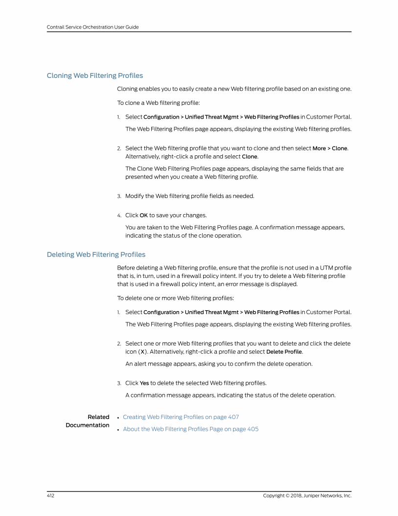
CloningWeb Filtering Profiles
Cloning enables you to easily create a newWeb filtering profile based on an existing one.
To clone aWeb filtering profile:
1. SelectConfiguration>UnifiedThreatMgmt>WebFilteringProfiles in Customer Portal.
TheWeb Filtering Profiles page appears, displaying the existingWeb filtering profiles.
2. Select theWeb filtering profile that you want to clone and then selectMore > Clone.
Alternatively, right-click a profile and select Clone.
The CloneWeb Filtering Profiles page appears, displaying the same fields that are
presented when you create aWeb filtering profile.
3. Modify theWeb filtering profile fields as needed.
4. ClickOK to save your changes.
You are taken to theWeb Filtering Profiles page. A confirmation message appears,
indicating the status of the clone operation.
DeletingWeb Filtering Profiles
Before deleting aWeb filtering profile, ensure that the profile is not used in a UTM profile
that is, in turn, used in a firewall policy intent. If you try to delete aWeb filtering profile
that is used in a firewall policy intent, an error message is displayed.
To delete one or moreWeb filtering profiles:
1. SelectConfiguration>UnifiedThreatMgmt>WebFilteringProfiles in Customer Portal.
TheWeb Filtering Profiles page appears, displaying the existingWeb filtering profiles.
2. Select one or moreWeb filtering profiles that you want to delete and click the delete
icon (X). Alternatively, right-click a profile and select Delete Profile.
An alert message appears, asking you to confirm the delete operation.
3. Click Yes to delete the selectedWeb filtering profiles.
A confirmation message appears, indicating the status of the delete operation.
RelatedDocumentation
CreatingWeb Filtering Profiles on page 407•
• About theWeb Filtering Profiles Page on page 405
Copyright © 2018, Juniper Networks, Inc.412
Contrail Service Orchestration User Guide
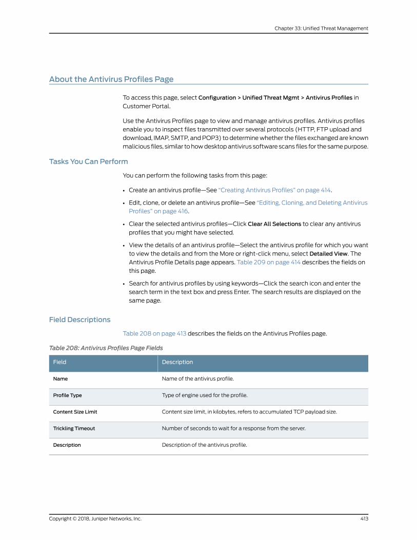
About the Antivirus Profiles Page
To access this page, select Configuration > Unified Threat Mgmt > Antivirus Profiles in
Customer Portal.
Use the Antivirus Profiles page to view andmanage antivirus profiles. Antivirus profiles
enable you to inspect files transmitted over several protocols (HTTP, FTP upload and
download, IMAP, SMTP, andPOP3) to determinewhether the files exchanged are known
malicious files, similar tohowdesktopantivirus software scans files for the samepurpose.
Tasks You Can Perform
You can perform the following tasks from this page:
• Create an antivirus profile—See “Creating Antivirus Profiles” on page 414.
• Edit, clone, or delete an antivirus profile—See “Editing, Cloning, and Deleting Antivirus
Profiles” on page 416.
• Clear the selected antivirus profiles—Click Clear All Selections to clear any antivirus
profiles that youmight have selected.
• View the details of an antivirus profile—Select the antivirus profile for which you want
to view the details and from the More or right-click menu, select Detailed View. The
Antivirus Profile Details page appears. Table 209 on page 414 describes the fields on
this page.
• Search for antivirus profiles by using keywords—Click the search icon and enter the
search term in the text box and press Enter. The search results are displayed on the
same page.
Field Descriptions
Table 208 on page 413 describes the fields on the Antivirus Profiles page.
Table 208: Antivirus Profiles Page Fields
DescriptionField
Name of the antivirus profile.Name
Type of engine used for the profile.Profile Type
Content size limit, in kilobytes, refers to accumulated TCP payload size.Content Size Limit
Number of seconds to wait for a response from the server.Trickling Timeout
Description of the antivirus profile.Description
413Copyright © 2018, Juniper Networks, Inc.
Chapter 33: Unified Threat Management
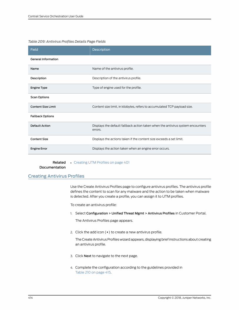
Table 209: Antivirus Profiles Details Page Fields
DescriptionField
General Information
Name of the antivirus profile.Name
Description of the antivirus profile.Description
Type of engine used for the profile.Engine Type
Scan Options
Content size limit, in kilobytes, refers to accumulated TCP payload size.Content Size Limit
Fallback Options
Displays the default fallback action taken when the antivirus system encounterserrors.
Default Action
Displays the actions taken if the content size exceeds a set limit.Content Size
Displays the action taken when an engine error occurs.Engine Error
RelatedDocumentation
Creating UTM Profiles on page 401•
Creating Antivirus Profiles
Use the Create Antivirus Profiles page to configure antivirus profiles. The antivirus profile
defines the content to scan for any malware and the action to be taken whenmalware
is detected. After you create a profile, you can assign it to UTM profiles.
To create an antivirus profile:
1. Select Configuration > Unified Threat Mgmt > Antivirus Profiles in Customer Portal.
The Antivirus Profiles page appears.
2. Click the add icon (+) to create a new antivirus profile.
TheCreateAntivirusProfileswizardappears, displayingbrief instructionsaboutcreating
an antivirus profile.
3. Click Next to navigate to the next page.
4. Complete the configuration according to the guidelines provided in
Table 210 on page 415.
Copyright © 2018, Juniper Networks, Inc.414
Contrail Service Orchestration User Guide
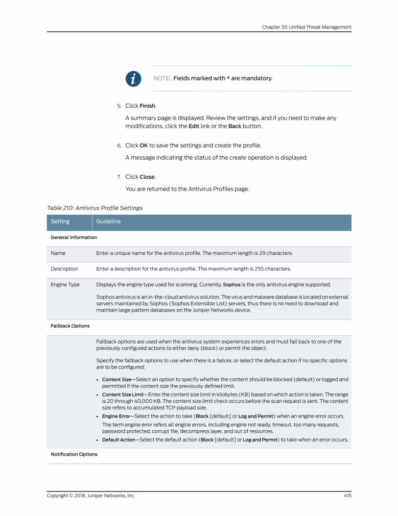
NOTE: Fieldsmarked with * aremandatory.
5. Click Finish.
A summary page is displayed. Review the settings, and if you need to make any
modifications, click the Edit link or the Back button.
6. ClickOK to save the settings and create the profile.
A message indicating the status of the create operation is displayed.
7. Click Close.
You are returned to the Antivirus Profiles page.
Table 210: Antivirus Profile Settings
GuidelineSetting
General Information
Enter a unique name for the antivirus profile. Themaximum length is 29 characters.Name
Enter a description for the antivirus profile. Themaximum length is 255 characters.Description
Displays the engine type used for scanning. Currently, Sophos is the only antivirus engine supported.
Sophos antivirus is an in-the-cloudantivirus solution. The virus andmalware database is locatedonexternalservers maintained by Sophos (Sophos Extensible List) servers, thus there is no need to download andmaintain large pattern databases on the Juniper Networks device.
Engine Type
Fallback Options
Fallback options are used when the antivirus system experiences errors andmust fall back to one of thepreviously configured actions to either deny (block) or permit the object.
Specify the fallback options to use when there is a failure, or select the default action if no specific optionsare to be configured:
• Content Size—Select an option to specify whether the content should be blocked (default) or logged andpermitted if the content size the previously defined limit.
• ContentSize Limit—Enter the content size limit in kilobytes (KB) based onwhich action is taken. The rangeis 20 through 40,000KB. The content size limit check occurs before the scan request is sent. The contentsize refers to accumulated TCP payload size.
• Engine Error—Select the action to take (Block [default] or Log and Permit) when an engine error occurs.
The term engine error refers all engine errors, including engine not ready, timeout, too many requests,password protected, corrupt file, decompress layer, and out of resources.
• Default Action—Select the default action (Block [default] or Log andPermit) to takewhen an error occurs.
Notification Options
415Copyright © 2018, Juniper Networks, Inc.
Chapter 33: Unified Threat Management
Table 210: Antivirus Profile Settings (continued)
GuidelineSetting
Use the notification options to configure a method of notifying the user when a fallback occurs or a virus isdetected:
• Fallback Deny—Select this option to notify mail senders that their messages were blocked.
• Fallback Non-Deny—Select this option to warn mail recipients that they received unblockedmessagesdespite problems.
• Virus Detected—Select this option to notify mail recipients that their messages were blocked.
RelatedDocumentation
Creating UTM Profiles on page 401•
Editing, Cloning, and Deleting Antivirus Profiles
You can edit, clone, and delete antivirus profiles from the Antivirus Profiles page. This
topic has the following sections:
• Editing Antivirus Profiles on page 416
• Cloning Antivirus Profiles on page 417
• Deleting Antivirus Profiles on page 417
Editing Antivirus Profiles
Tomodify the parameters configured for an antivirus profile:
NOTE: You cannotmodify the default profiles already present in the system.
1. Select Configuration > Unified Threat Mgmt > Antivirus Profiles in Customer Portal.
The Antivirus Profiles page appears, displaying the existing antivirus profiles.
2. Select the antivirus profile that youwant to edit and then select the edit icon (pencil).
Alternatively, right-click a profile and select Edit Antivirus Profile.
TheEdit AntivirusProfiles pageappears, displaying the same fields that arepresented
when you create an antivirus profile.
3. Modify the antivirus profile fields as needed.
4. ClickOK to save your changes.
You are taken to the Antivirus Profiles page. A confirmation message appears,
indicating the status of the edit operation.
Copyright © 2018, Juniper Networks, Inc.416
Contrail Service Orchestration User Guide
Cloning Antivirus Profiles
Cloning enables you to easily create a new antivirus profile based on an existing one.
To clone an antivirus profile:
1. Select Configuration > Unified Threat Mgmt > Antivirus Profiles in Customer Portal.
The Antivirus Profiles page appears, displaying the existing antivirus profiles.
2. Select the antivirus profile that you want to clone and then selectMore > Clone.
Alternatively, right-click a profile and select Clone.
TheCloneAntivirusProfilespageappears, displaying thesamefields thatarepresented
when you create an antivirus profile.
3. Modify the antivirus profile fields as needed.
4. ClickOK to save your changes.
You are taken to the Antivirus Profiles page. A confirmation message appears,
indicating the status of the clone operation.
Deleting Antivirus Profiles
Before deleting an antivirus profile, ensure that the profile is not used in a UTM profile
that is, in turn, used in a firewall policy intent. If you try to delete an antivirus profile that
is used in a firewall policy intent, an error message is displayed.
To delete one or more antivirus profiles:
1. Select Configuration > Unified Threat Mgmt > Antivirus Profiles in Customer Portal.
The Antivirus Profiles page appears, displaying the existing antivirus profiles.
2. Select oneormoreantivirusprofiles that youwant todeleteand thenselect thedelete
icon (X). Alternatively, right-click a profile and select Delete Antivirus Profiles.
An alert message appears, asking you to confirm the delete operation.
3. Click Yes to delete the selected antivirus profiles.
A confirmation message appears, indicating the status of the delete operation.
RelatedDocumentation
Creating Antivirus Profiles on page 414•
• About the Antivirus Profiles Page on page 413
417Copyright © 2018, Juniper Networks, Inc.
Chapter 33: Unified Threat Management
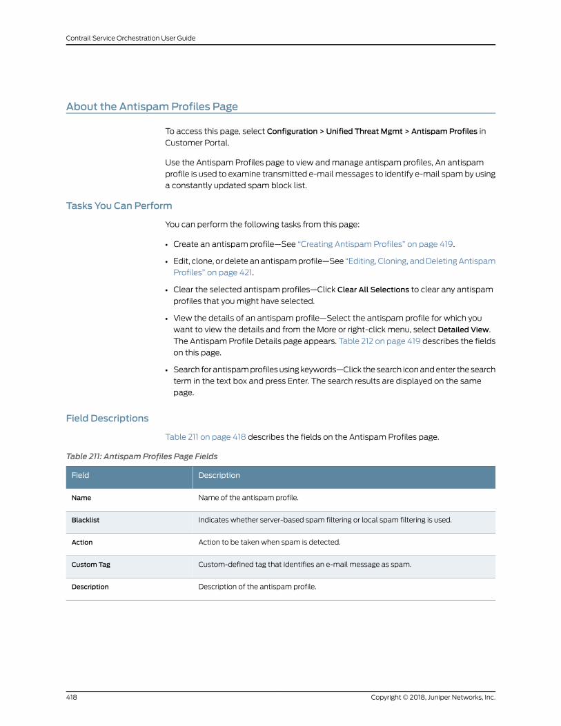
About the AntispamProfiles Page
To access this page, select Configuration > Unified Threat Mgmt > AntispamProfiles in
Customer Portal.
Use the Antispam Profiles page to view andmanage antispam profiles, An antispam
profile is used to examine transmitted e-mail messages to identify e-mail spamby using
a constantly updated spam block list.
Tasks You Can Perform
You can perform the following tasks from this page:
• Create an antispam profile—See “Creating Antispam Profiles” on page 419.
• Edit, clone, or deleteanantispamprofile—See “Editing, Cloning, andDeletingAntispam
Profiles” on page 421.
• Clear the selected antispam profiles—Click Clear All Selections to clear any antispam
profiles that youmight have selected.
• View the details of an antispam profile—Select the antispam profile for which you
want to view the details and from the More or right-click menu, select Detailed View.
The AntispamProfile Details page appears. Table 212 on page 419 describes the fields
on this page.
• Search for antispamprofilesusingkeywords—Click thesearch iconandenter the search
term in the text box and press Enter. The search results are displayed on the same
page.
Field Descriptions
Table 211 on page 418 describes the fields on the Antispam Profiles page.
Table 211: Antispam Profiles Page Fields
DescriptionField
Name of the antispam profile.Name
Indicates whether server-based spam filtering or local spam filtering is used.Blacklist
Action to be taken when spam is detected.Action
Custom-defined tag that identifies an e-mail message as spam.Custom Tag
Description of the antispam profile.Description
Copyright © 2018, Juniper Networks, Inc.418
Contrail Service Orchestration User Guide
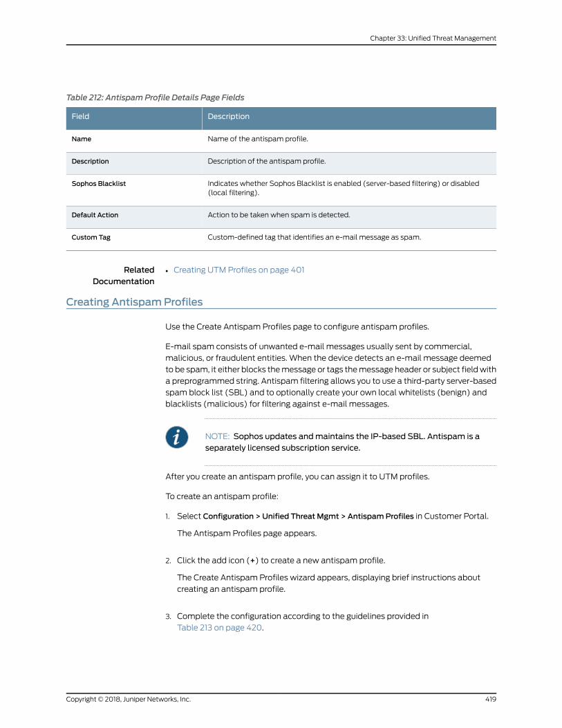
Table 212: Antispam Profile Details Page Fields
DescriptionField
Name of the antispam profile.Name
Description of the antispam profile.Description
Indicates whether Sophos Blacklist is enabled (server-based filtering) or disabled(local filtering).
Sophos Blacklist
Action to be taken when spam is detected.Default Action
Custom-defined tag that identifies an e-mail message as spam.Custom Tag
RelatedDocumentation
Creating UTM Profiles on page 401•
Creating AntispamProfiles
Use the Create Antispam Profiles page to configure antispam profiles.
E-mail spam consists of unwanted e-mail messages usually sent by commercial,
malicious, or fraudulent entities. When the device detects an e-mail message deemed
to be spam, it either blocks themessage or tags themessage header or subject fieldwith
a preprogrammed string. Antispam filtering allows you to use a third-party server-based
spam block list (SBL) and to optionally create your own local whitelists (benign) and
blacklists (malicious) for filtering against e-mail messages.
NOTE: Sophos updates andmaintains the IP-based SBL. Antispam is aseparately licensed subscription service.
After you create an antispam profile, you can assign it to UTM profiles.
To create an antispam profile:
1. Select Configuration > Unified Threat Mgmt > AntispamProfiles in Customer Portal.
The Antispam Profiles page appears.
2. Click the add icon (+) to create a new antispam profile.
The Create Antispam Profiles wizard appears, displaying brief instructions about
creating an antispam profile.
3. Complete the configuration according to the guidelines provided in
Table 213 on page 420.
419Copyright © 2018, Juniper Networks, Inc.
Chapter 33: Unified Threat Management
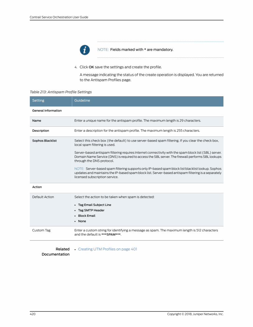
NOTE: Fieldsmarked with * aremandatory.
4. ClickOK save the settings and create the profile.
Amessage indicating the status of the create operation is displayed. You are returned
to the Antispam Profiles page.
Table 213: Antispam Profile Settings
GuidelineSetting
General Information
Enter a unique name for the antispam profile. Themaximum length is 29 characters.Name
Enter a description for the antispam profile. Themaximum length is 255 characters.Description
Select this check box (the default) to use server-based spam filtering. If you clear the check box,local spam filtering is used.
Server-basedantispam filtering requires Internet connectivitywith the spamblock list (SBL) server.DomainNameService (DNS) is required toaccess theSBLserver. The firewall performsSBL lookupsthrough the DNS protocol.
NOTE: Server-basedspamfiltering supportsonly IP-basedspamblock list blacklist lookup.Sophosupdatesandmaintains the IP-basedspamblock list. Server-basedantispamfiltering is a separatelylicensed subscription service.
Sophos Blacklist
Action
Select the action to be taken when spam is detected:
• Tag Email Subject Line
• Tag SMTPHeader
• Block Email
• None
Default Action
Enter a custom string for identifying amessage as spam. Themaximum length is 512 charactersand the default is ***SPAM***.
Custom Tag
RelatedDocumentation
Creating UTM Profiles on page 401•
Copyright © 2018, Juniper Networks, Inc.420
Contrail Service Orchestration User Guide
Editing, Cloning, and Deleting AntispamProfiles
You can edit, clone, and delete antispam profiles from the Antispam Profiles page. This
topic has the following sections:
• Editing Antispam Profiles on page 421
• Cloning Antispam Profiles on page 421
• Deleting Antispam Profiles on page 422
Editing AntispamProfiles
Tomodify the parameters configured for an antispam profile:
NOTE: You cannotmodify the default profiles already present in the system.
1. Select Configuration > Unified Threat Mgmt > AntispamProfiles in Customer Portal.
The Antispam Profiles page appears, displaying the existing antispam profiles.
2. Select the antispam profile that you want to edit and click the edit icon (pencil).
Alternatively, right-click a profile and select Edit AntispamProfile.
TheEditAntispamProfilespageappears, displaying thesame fields thatarepresented
when you create an antispam profile.
3. Modify the antispam profile fields as needed.
4. ClickOK to save your changes.
You are taken to the Antispam Profiles page. A confirmation message appears,
indicating the status of the edit operation.
Cloning AntispamProfiles
Cloning enables you to easily create a new antispam profile based on an existing one.
To clone an antispam profile:
1. Select Configuration > Unified Threat Mgmt > AntispamProfiles in Customer Portal.
The Antispam Profiles page appears displaying the existing antispam profiles.
2. Select the antispam profile that you want to clone and then selectMore > Clone.
Alternatively, right-click a profile and select Clone.
The Clone Antispam Profiles page appears, displaying the same fields that are
presented when you create an antispam profile.
421Copyright © 2018, Juniper Networks, Inc.
Chapter 33: Unified Threat Management
3. Modify the antispam profile fields as needed.
4. ClickOK to save your changes.
You are taken to the Antispam Profiles page. A confirmation message appears,
indicating the status of the clone operation.
Deleting AntispamProfiles
Before deleting an antispam profile, ensure that the profile is not used in a UTM profile
that is, in turn, used in a firewall policy intent. If you try to delete an antispam profile that
is used in a firewall policy intent, an error message is displayed.
To delete one or more antispam profiles:
1. Select Configuration > Unified Threat Mgmt > AntispamProfiles in Customer Portal.
The Antispam Profiles page appears, displaying the existing antispam profiles.
2. Select one ormore antispamprofiles that youwant to delete and click the delete icon
(X). Alternatively, right-click a profile and select Delete AntispamProfiles.
An alert message appears, asking you to confirm the delete operation.
3. Click Yes to delete the selected antispam profiles.
A confirmation message appears, indicating the status of the delete operation.
RelatedDocumentation
About the Antispam Profiles Page on page 418•
About the Content Filtering Profiles Page
Toaccess thispage, selectConfiguration>UnifiedThreatMgmt>ContentFilteringProfiles
in Customer Portal.
Use the Content Filtering Profiles page to view andmanage content filtering profiles.
Content filtering profiles enable you to block or permit certain types of traffic over several
protocols (HTTP, FTP upload and download, IMAP, SMTP, and POP3) based on the
MIME type, file extension, protocol command, and embedded object type.
Tasks You Can Perform
You can perform the following tasks from this page:
• Createacontent filteringprofile—See “CreatingContent FilteringProfiles” onpage424.
• Edit, clone, or delete a content filtering profile—See “Editing, Cloning, and Deleting
Content Filtering Profiles” on page 427.
• Clear the selected content filtering profiles—Click Clear All Selections to clear any
content filtering profiles that youmight have selected.
Copyright © 2018, Juniper Networks, Inc.422
Contrail Service Orchestration User Guide
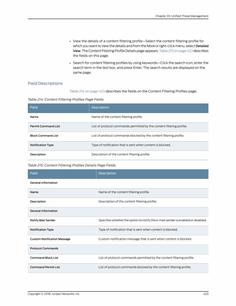
• View the details of a content filtering profile—Select the content filtering profile for
whichyouwant toviewthedetailsand fromtheMoreor right-clickmenu, selectDetailed
View. TheContentFilteringProfileDetailspageappears.Table215onpage423describes
the fields on this page.
• Search for content filtering profiles by using keywords—Click the search icon, enter the
search term in the text box, and press Enter. The search results are displayed on the
same page.
Field Descriptions
Table 214 on page 423 describes the fields on the Content Filtering Profiles page.
Table 214: Content Filtering Profiles Page Fields
DescriptionField
Name of the content filtering profile.Name
List of protocol commands permitted by the content filtering profile.Permit Command List
List of protocol commands blocked by the content filtering profile.Block Command List
Type of notification that is sent when content is blocked.Notification Type
Description of the content filtering profile.Description
Table 215: Content Filtering Profiles Details Page Fields
DescriptionField
General Information
Name of the content filtering profile.Name
Description of the content filtering profile.Description
General Information
Specifieswhether theoption tonotify thee-mail sender is enabledordisabled.Notify Mail Sender
Type of notification that is sent when content is blocked.Notification Type
Custom notification message that is sent when content is blocked.CustomNotificationMessage
Protocol Commands
List of protocol commands permitted by the content filtering profile.Command Block List
List of protocol commands blocked by the content filtering profile.Command Permit List
423Copyright © 2018, Juniper Networks, Inc.
Chapter 33: Unified Threat Management
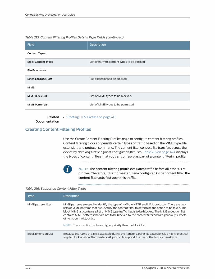
Table 215: Content Filtering Profiles Details Page Fields (continued)
DescriptionField
Content Types
List of harmful content types to be blocked.Block Content Types
File Extensions
File extensions to be blocked.Extension Block List
MIME
List of MIME types to be blocked.MIME Block List
List of MIME types to be permitted.MIME Permit List
RelatedDocumentation
Creating UTM Profiles on page 401•
Creating Content Filtering Profiles
Use the Create Content Filtering Profiles page to configure content filtering profiles.
Content filtering blocks or permits certain types of traffic based on the MIME type, file
extension, and protocol command. The content filter controls file transfers across the
device by checking traffic against configured filter lists. Table 216 on page 424 displays
the types of content filters that you can configure as part of a content filtering profile.
NOTE: The content filtering profile evaluates traffic before all other UTMprofiles. Therefore, if trafficmeets criteria configured in the content filter, thecontent filter acts first upon this traffic.
Table 216: Supported Content Filter Types
DescriptionType
MIME patterns are used to identify the type of traffic in HTTP and MAIL protocols. There are twolists of MIME patterns that are used by the content filter to determine the action to be taken. Theblock MIME list contains a list of MIME type traffic that is to be blocked. The MIME exception listcontains MIME patterns that are not to be blocked by the content filter and are generally subsetsof items on the block list.
NOTE: The exception list has a higher priority than the block list.
MIME pattern filter
Because the nameof a file is available during the transfers, using file extensions is a highly practicalway to block or allow file transfers. All protocols support the use of the block extension list.
Block Extension List
Copyright © 2018, Juniper Networks, Inc.424
Contrail Service Orchestration User Guide
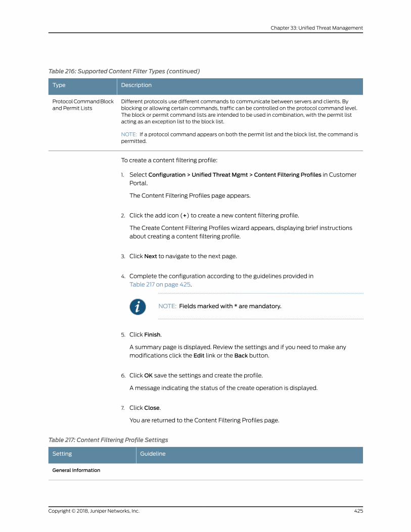
Table 216: Supported Content Filter Types (continued)
DescriptionType
Different protocols use different commands to communicate between servers and clients. Byblocking or allowing certain commands, traffic can be controlled on the protocol command level.The block or permit command lists are intended to be used in combination, with the permit listacting as an exception list to the block list.
NOTE: If a protocol command appears on both the permit list and the block list, the command ispermitted.
ProtocolCommandBlockand Permit Lists
To create a content filtering profile:
1. Select Configuration > Unified Threat Mgmt > Content Filtering Profiles in Customer
Portal.
The Content Filtering Profiles page appears.
2. Click the add icon (+) to create a new content filtering profile.
The Create Content Filtering Profiles wizard appears, displaying brief instructions
about creating a content filtering profile.
3. Click Next to navigate to the next page.
4. Complete the configuration according to the guidelines provided in
Table 217 on page 425.
NOTE: Fieldsmarked with * aremandatory.
5. Click Finish.
A summary page is displayed. Review the settings and if you need to make any
modifications click the Edit link or the Back button.
6. ClickOK save the settings and create the profile.
A message indicating the status of the create operation is displayed.
7. Click Close.
You are returned to the Content Filtering Profiles page.
Table 217: Content Filtering Profile Settings
GuidelineSetting
General Information
425Copyright © 2018, Juniper Networks, Inc.
Chapter 33: Unified Threat Management
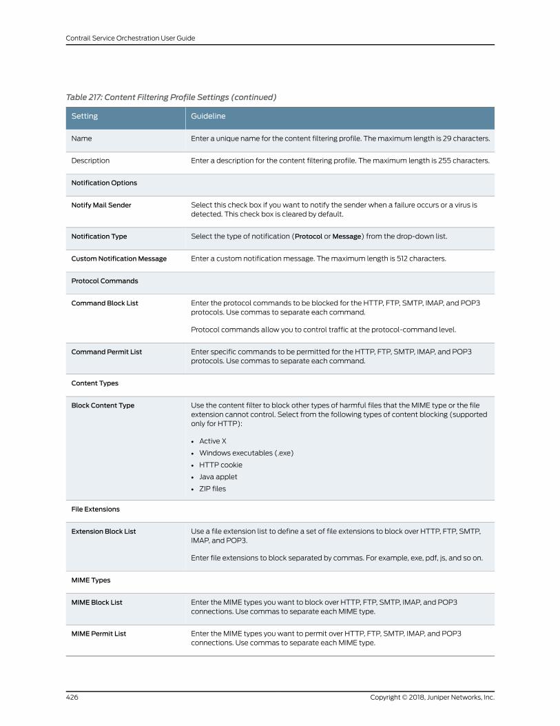
Table 217: Content Filtering Profile Settings (continued)
GuidelineSetting
Enter a unique name for the content filtering profile. Themaximum length is 29 characters.Name
Enter a description for the content filtering profile. Themaximum length is 255 characters.Description
Notification Options
Select this check box if you want to notify the sender when a failure occurs or a virus isdetected. This check box is cleared by default.
Notify Mail Sender
Select the type of notification (Protocol orMessage) from the drop-down list.Notification Type
Enter a custom notification message. Themaximum length is 512 characters.CustomNotificationMessage
Protocol Commands
Enter the protocol commands to be blocked for the HTTP, FTP, SMTP, IMAP, and POP3protocols. Use commas to separate each command.
Protocol commands allow you to control traffic at the protocol-command level.
Command Block List
Enter specific commands to be permitted for the HTTP, FTP, SMTP, IMAP, and POP3protocols. Use commas to separate each command.
Command Permit List
Content Types
Use the content filter to block other types of harmful files that the MIME type or the fileextension cannot control. Select from the following types of content blocking (supportedonly for HTTP):
• Active X
• Windows executables (.exe)
• HTTP cookie
• Java applet
• ZIP files
Block Content Type
File Extensions
Use a file extension list to define a set of file extensions to block over HTTP, FTP, SMTP,IMAP, and POP3.
Enter file extensions to block separated by commas. For example, exe, pdf, js, and so on.
Extension Block List
MIME Types
Enter the MIME types you want to block over HTTP, FTP, SMTP, IMAP, and POP3connections. Use commas to separate each MIME type.
MIME Block List
Enter the MIME types you want to permit over HTTP, FTP, SMTP, IMAP, and POP3connections. Use commas to separate each MIME type.
MIME Permit List
Copyright © 2018, Juniper Networks, Inc.426
Contrail Service Orchestration User Guide
RelatedDocumentation
Creating UTM Profiles on page 401•
Editing, Cloning, and Deleting Content Filtering Profiles
Youcanedit, clone, anddelete content filteringprofiles fromtheContent FilteringProfiles
page. This topic has the following sections:
• Editing Content Filtering Profiles on page 427
• Cloning Content Filtering Profiles on page 427
• Deleting Content Filtering Profiles on page 428
Editing Content Filtering Profiles
Tomodify the parameters configured for a content filtering profile:
NOTE: You cannotmodify the default profiles already present in the system.
1. Select Configuration > Unified Threat Mgmt > Content Filtering Profiles in Customer
Portal.
The Content Filtering Profiles page appears, displaying the existing content filtering
profiles.
2. Select the content filteringprofile that youwant to edit and click the edit icon (pencil).
Alternatively, right-click a profile and select Edit Profile.
The Edit Content Filtering Profiles page appears, displaying the same fields that are
presented when you create a content filtering profile.
3. Modify the content filtering profile fields as needed.
4. ClickOK to save your changes.
You are taken to the Content Filtering Profiles page. A confirmationmessage appears,
indicating the status of the edit operation.
Cloning Content Filtering Profiles
Cloning enables you to easily create a new content filtering profile based on an existing
one.
427Copyright © 2018, Juniper Networks, Inc.
Chapter 33: Unified Threat Management
To clone a content filtering profile:
1. Select Configuration > Unified Threat Mgmt > Content Filtering Profiles in Customer
Portal.
The Content Filtering Profiles page appears, displaying the existing content filtering
profiles.
2. Select the content filteringprofile that youwant to cloneand then selectMore>Clone.
Alternatively, right-click a profile and select Clone.
The Clone Content Filtering Profiles page appears, displaying the same fields that are
presented when you create a content filtering profile.
3. Modify the content filtering profile fields as needed.
4. ClickOK to save your changes.
You are taken to the Content Filtering Profiles page. A confirmationmessage appears,
indicating the status of the clone operation.
Deleting Content Filtering Profiles
Before deleting a content filtering profile, ensure that the profile is not used in a UTM
profile that is, in turn, used in a firewall policy intent. If you try to delete a content filtering
profile that is used in a firewall policy intent, an error message is displayed.
To delete one or more content filtering profiles:
1. Select Configuration > Unified Threat Mgmt > Content Filtering Profiles in Customer
Portal.
The Content Filtering Profiles page appears, displaying the existing content filtering
profiles.
2. Select one or more content filtering profiles that you want to delete and click the
delete icon (X). Alternatively, right-click a profile and select Delete Profile.
An alert message appears, asking you to confirm the delete operation.
3. Click Yes to delete the selected content filtering profiles.
A confirmation message appears, indicating the status of the delete operation.
RelatedDocumentation
Creating Content Filtering Profiles on page 424•
Copyright © 2018, Juniper Networks, Inc.428
Contrail Service Orchestration User Guide
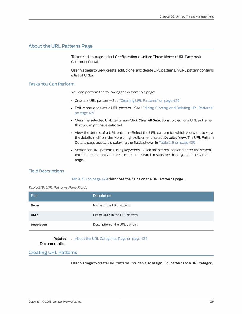
About the URL Patterns Page
To access this page, select Configuration > Unified Threat Mgmt > URL Patterns in
Customer Portal.
Use this page to view, create, edit, clone, anddeleteURLpatterns. AURLpattern contains
a list of URLs.
Tasks You Can Perform
You can perform the following tasks from this page:
• Create a URL pattern—See “Creating URL Patterns” on page 429.
• Edit, clone, or delete a URL pattern—See “Editing, Cloning, and Deleting URL Patterns”
on page 431.
• Clear the selected URL patterns—Click Clear All Selections to clear any URL patterns
that youmight have selected.
• View the details of a URL pattern—Select the URL pattern for which you want to view
thedetails and fromtheMoreor right-clickmenu, selectDetailedView. TheURLPattern
Details page appears displaying the fields shown in Table 218 on page 429.
• Search for URL patterns using keywords—Click the search icon and enter the search
term in the text box and press Enter. The search results are displayed on the same
page.
Field Descriptions
Table 218 on page 429 describes the fields on the URL Patterns page.
Table 218: URL Patterns Page Fields
DescriptionField
Name of the URL pattern.Name
List of URLs in the URL pattern.URLs
Description of the URL pattern.Description
RelatedDocumentation
About the URL Categories Page on page 432•
Creating URL Patterns
Use this page tocreateURLpatterns. YoucanalsoassignURLpatterns toaURLcategory.
429Copyright © 2018, Juniper Networks, Inc.
Chapter 33: Unified Threat Management
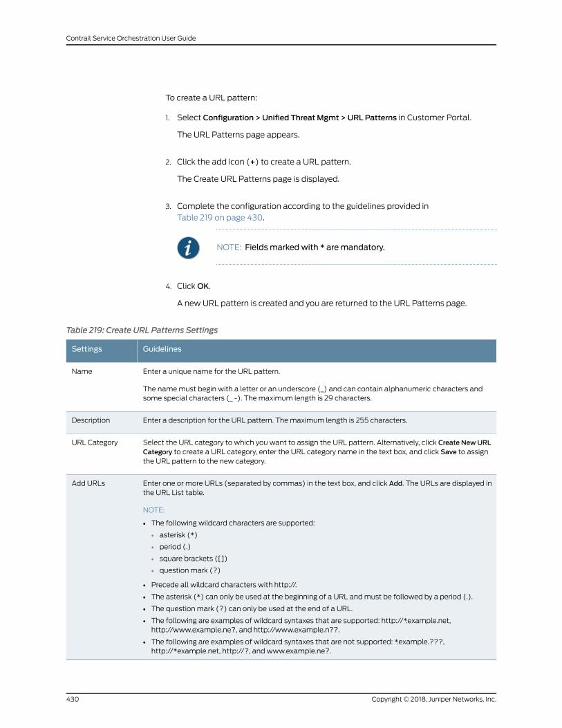
To create a URL pattern:
1. Select Configuration > Unified Threat Mgmt > URL Patterns in Customer Portal.
The URL Patterns page appears.
2. Click the add icon (+) to create a URL pattern.
The Create URL Patterns page is displayed.
3. Complete the configuration according to the guidelines provided in
Table 219 on page 430.
NOTE: Fieldsmarked with * aremandatory.
4. ClickOK.
A new URL pattern is created and you are returned to the URL Patterns page.
Table 219: Create URL Patterns Settings
GuidelinesSettings
Enter a unique name for the URL pattern.
The namemust begin with a letter or an underscore (_) and can contain alphanumeric characters andsome special characters (_ -). Themaximum length is 29 characters.
Name
Enter a description for the URL pattern. Themaximum length is 255 characters.Description
Select the URL category to which you want to assign the URL pattern. Alternatively, click Create NewURLCategory to create a URL category, enter the URL category name in the text box, and click Save to assignthe URL pattern to the new category.
URL Category
Enter one or more URLs (separated by commas) in the text box, and click Add. The URLs are displayed inthe URL List table.
NOTE:
• The following wildcard characters are supported:
• asterisk (*)
• period (.)
• square brackets ([])
• question mark (?)
• Precede all wildcard characters with http://.
• The asterisk (*) can only be used at the beginning of a URL andmust be followed by a period (.).
• The question mark (?) can only be used at the end of a URL.
• The following are examples of wildcard syntaxes that are supported: http://*.example.net,http://www.example.ne?, and http://www.example.n??.
• The following are examples of wildcard syntaxes that are not supported: *.example.???,http://*example.net, http://?, and www.example.ne?.
Add URLs
Copyright © 2018, Juniper Networks, Inc.430
Contrail Service Orchestration User Guide
RelatedDocumentation
Creating URL Categories on page 433•
Editing, Cloning, and Deleting URL Patterns
You can edit, clone, and delete URL patterns from the URL Patterns page. This topic has
the following sections:
• Editing URL Patterns on page 431
• Cloning URL Patterns on page 431
• Deleting URL Patterns on page 432
Editing URL Patterns
Tomodify the parameters configured for a URL pattern:
1. Select Configuration > Unified Threat Mgmt > URL Patterns in Customer Portal.
The URL Patterns page appears, displaying the existing URL patterns.
2. Select the URL pattern that you want to edit and click the edit icon (pencil).
Alternatively, right-click a pattern and select Edit URL Patterns.
The Edit URL Patterns page appears, displaying the same fields that are presented
when you create a URL pattern.
3. Modify the URL pattern fields as needed.
4. ClickOK to save your changes.
You are taken to the URL Patterns page. A confirmation message appears, indicating
the status of the edit operation.
Cloning URL Patterns
Cloning enables you to easily create a new URL pattern based on an existing one.
To clone a URL pattern:
1. Select Configuration > Unified Threat Mgmt > URL Patterns in Customer Portal.
The URL Patterns page appears, displaying the existing URL patterns.
2. Select the URL pattern that you want to clone and then selectMore > Clone.
Alternatively, right-click a pattern and select Clone.
The Clone URL Patterns page appears, displaying the same fields that are presented
when you create a URL pattern.
431Copyright © 2018, Juniper Networks, Inc.
Chapter 33: Unified Threat Management
3. Modify the URL pattern fields as needed.
4. ClickOK to save your changes.
You are taken to the URL Patterns page. A confirmation message appears, indicating
the status of the clone operation.
Deleting URL Patterns
Before deleting a URL pattern, ensure that the URL pattern is not referenced in any UTM
profiles that are, in turn, used in firewall policy intents or in URL categories referenced in
the UTM settings. If you try to delete such a URL pattern, an error message is displayed.
To delete one or more URL patterns:
1. Select Configuration > Unified Threat Mgmt > URL Patterns in Customer Portal.
The URL Patterns page appears, displaying the existing URL patterns.
2. Select one or more URL patterns that you want to delete and click the delete icon
(X). Alternatively, right-click a pattern and select Delete URL Pattern.
An alert message appears, asking you to confirm the delete operation.
3. Click Yes to delete the selected URL patterns.
A confirmation message appears, indicating the status of the delete operation.
RelatedDocumentation
Creating URL Patterns on page 429•
About the URL Categories Page
To access this page, select Configuration > Unified Threat Mgmt > URL Categories in
Customer Portal.
Use this page to view, create, edit, clone, and delete URL categories. A URL category is
a list of URL patterns grouped under a single title.
Tasks You Can Perform
You can perform the following tasks from this page:
• Create a URL category—See “Creating URL Categories” on page 433.
• Edit, clone, or delete a URL category—See “Editing, Cloning, and Deleting URL
Categories” on page 434.
• Clear the selectedURLcategories—ClickClearAllSelections to clear anyURLcategories
that youmight have selected.
Copyright © 2018, Juniper Networks, Inc.432
Contrail Service Orchestration User Guide
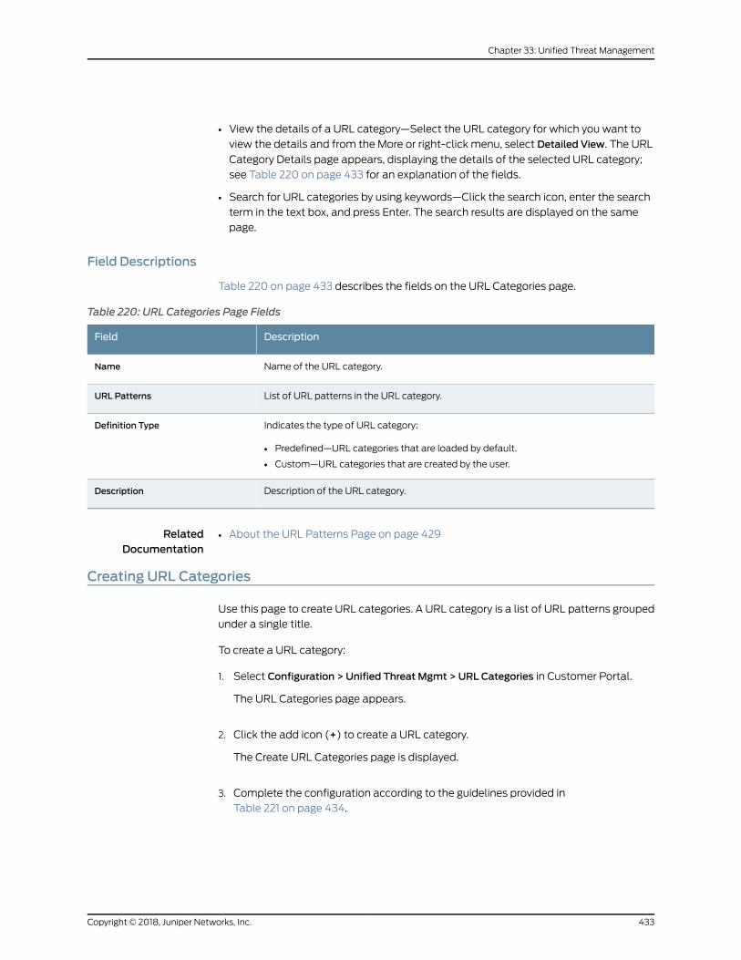
• View the details of a URL category—Select the URL category for which you want to
view the details and from the More or right-click menu, select Detailed View. The URL
Category Details page appears, displaying the details of the selected URL category;
see Table 220 on page 433 for an explanation of the fields.
• Search for URL categories by using keywords—Click the search icon, enter the search
term in the text box, and press Enter. The search results are displayed on the same
page.
Field Descriptions
Table 220 on page 433 describes the fields on the URL Categories page.
Table 220: URL Categories Page Fields
DescriptionField
Name of the URL category.Name
List of URL patterns in the URL category.URL Patterns
Indicates the type of URL category:
• Predefined—URL categories that are loaded by default.
• Custom—URL categories that are created by the user.
Definition Type
Description of the URL category.Description
RelatedDocumentation
About the URL Patterns Page on page 429•
Creating URL Categories
Use this page to create URL categories. A URL category is a list of URL patterns grouped
under a single title.
To create a URL category:
1. Select Configuration > Unified Threat Mgmt > URL Categories in Customer Portal.
The URL Categories page appears.
2. Click the add icon (+) to create a URL category.
The Create URL Categories page is displayed.
3. Complete the configuration according to the guidelines provided in
Table 221 on page 434.
433Copyright © 2018, Juniper Networks, Inc.
Chapter 33: Unified Threat Management
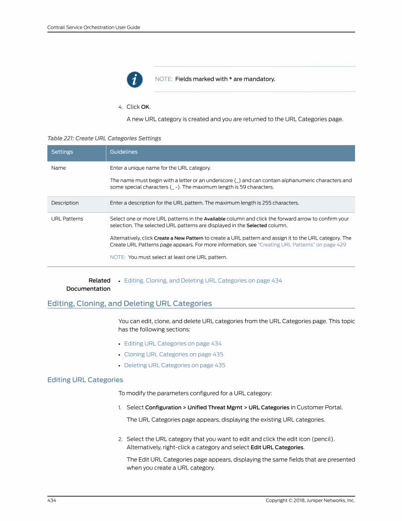
NOTE: Fieldsmarked with * aremandatory.
4. ClickOK.
A new URL category is created and you are returned to the URL Categories page.
Table 221: Create URL Categories Settings
GuidelinesSettings
Enter a unique name for the URL category.
The namemust begin with a letter or an underscore (_) and can contain alphanumeric characters andsome special characters (_ -). Themaximum length is 59 characters.
Name
Enter a description for the URL pattern. Themaximum length is 255 characters.Description
Select one or more URL patterns in the Available column and click the forward arrow to confirm yourselection. The selected URL patterns are displayed in the Selected column.
Alternatively, click Create a NewPattern to create a URL pattern and assign it to the URL category. TheCreate URL Patterns page appears. For more information, see “Creating URL Patterns” on page 429
NOTE: Youmust select at least one URL pattern.
URL Patterns
RelatedDocumentation
Editing, Cloning, and Deleting URL Categories on page 434•
Editing, Cloning, and Deleting URL Categories
You can edit, clone, and delete URL categories from the URL Categories page. This topic
has the following sections:
• Editing URL Categories on page 434
• Cloning URL Categories on page 435
• Deleting URL Categories on page 435
Editing URL Categories
Tomodify the parameters configured for a URL category:
1. Select Configuration > Unified Threat Mgmt > URL Categories in Customer Portal.
The URL Categories page appears, displaying the existing URL categories.
2. Select the URL category that you want to edit and click the edit icon (pencil).
Alternatively, right-click a category and select Edit URL Categories.
The Edit URL Categories page appears, displaying the same fields that are presented
when you create a URL category.
Copyright © 2018, Juniper Networks, Inc.434
Contrail Service Orchestration User Guide
3. Modify the URL category fields as needed.
4. ClickOK to save your changes.
Youare taken to theURLCategoriespage.Aconfirmationmessageappears, indicating
the status of the edit operation.
Cloning URL Categories
Cloning enables you to easily create a new URL category based on an existing one.
To clone a URL category:
1. Select Configuration > Unified Threat Mgmt > URL Categories in Customer Portal.
The URL Categories page appears, displaying the existing URL categories.
2. Select the URL category that you want to clone and then selectMore > Clone.
Alternatively, right-click a category and select Clone.
TheCloneURLCategoriespageappears, displaying thesamefields thatarepresented
when you create a URL category.
3. Modify the URL category fields as needed.
4. ClickOK to save your changes.
Youare taken to theURLCategoriespage.Aconfirmationmessageappears, indicating
the status of the clone operation.
Deleting URL Categories
Before deleting a URL category, ensure that the URL category is not referenced in any
UTM profiles that are, in turn, used in firewall policy intents or in the UTM settings. If you
try to delete such a URL category, an error message is displayed.
To delete one or more URL categories:
1. Select Configuration > Unified Threat Mgmt > URL Categories in Customer Portal.
The URL Categories page appears, displaying the existing URL categories.
2. Select one or more URL categories that you want to delete and click the delete icon
(X). Alternatively, right-click a category and select Delete URL Category.
An alert message appears, asking you to confirm the delete operation.
3. Click Yes to delete the selected URL categories.
A confirmation message appears, indicating the status of the delete operation.
435Copyright © 2018, Juniper Networks, Inc.
Chapter 33: Unified Threat Management

RelatedDocumentation
• Creating URL Categories on page 433
Copyright © 2018, Juniper Networks, Inc.436
Contrail Service Orchestration User Guide
CHAPTER 34
Managing SD-WAN
• SLA Profiles and SD-WAN Policies Overview on page 437
• About the SD-WAN Policy Page on page 440
• Creating SD-WAN Policy Intents on page 441
• Editing and Deleting SD-WAN Policy Intents on page 445
• About the Application SLA Profiles Page on page 446
• Creating SLA Profiles on page 447
• Editing and Deleting SLA Profiles on page 449
SLA Profiles and SD-WANPolicies Overview
Contrail Service Orchestration (CSO) enables you to create service-level agreement
(SLA) profiles andmap them to software-definedWAN (SD-WAN) policies for traffic
management.
SLA Profiles
SLA profiles are created for applications or groups of applications for all tenants. An SLA
profile consists of a set of configurable constraints that can be defined in the unified
portal for both the Administration and Customer Portals. Table 87 on page 164 lists the
categories of configurable constraints that are defined in an SLA profile.
Table 222: SLA Profile Categories
DescriptionCategory
Paths are theWAN links to be used for the SLA profile. You can select an MPLS or Internet link asthepreferredpath. ForSLAprofiles thatareused for localbreakout, youmust selectapathpreference.For SLA profiles that are not associated with local breakout, youmust select a path preference orconfigure at least one SLA parameter. MPLS is more latency-sensitive than Internet.
You can define priority or precedence for the SLA profile. A value of one (1) indicates highest priority.SLAprofileswith higher priorities are givenprecedenceover SLAprofileswith lower priorities. Priorityis used when SLA requirements are not met on aWAN link and the site switchesWAN links tomeetthe SLA requirements.
Path preference andpriority
437Copyright © 2018, Juniper Networks, Inc.
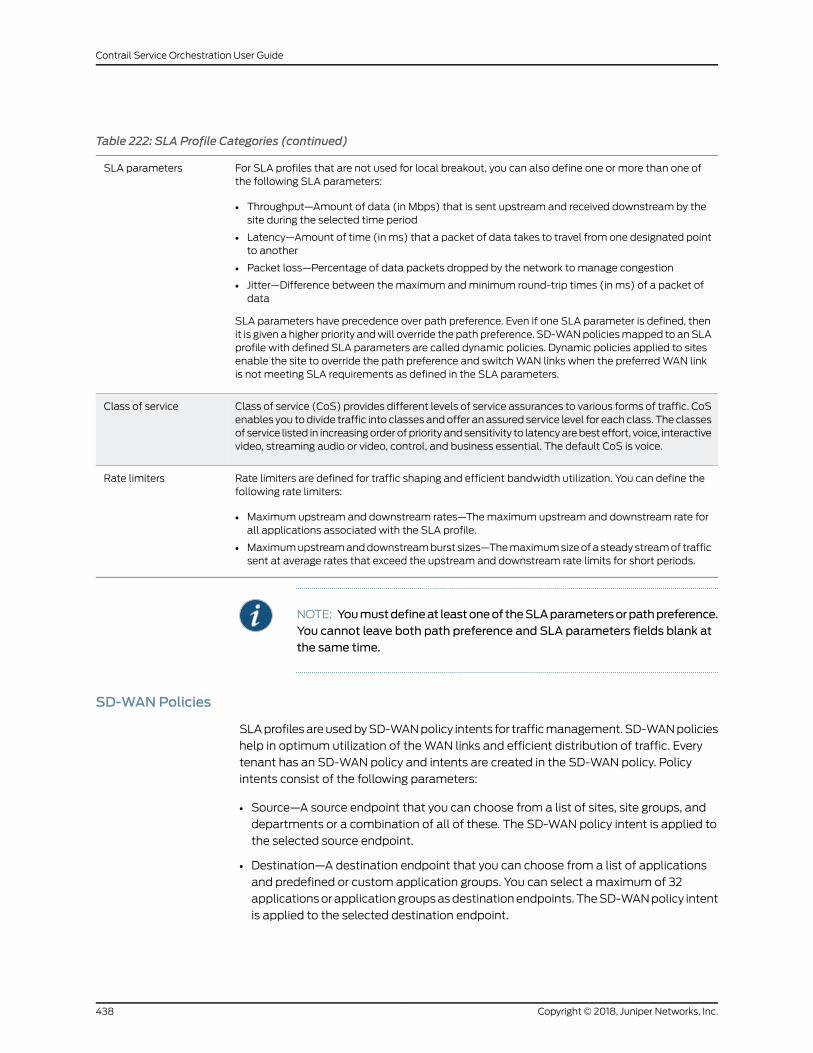
Table 222: SLA Profile Categories (continued)
For SLA profiles that are not used for local breakout, you can also define one or more than one ofthe following SLA parameters:
• Throughput—Amount of data (in Mbps) that is sent upstream and received downstream by thesite during the selected time period
• Latency—Amount of time (inms) that a packet of data takes to travel from one designated pointto another
• Packet loss—Percentage of data packets dropped by the network to manage congestion
• Jitter—Difference between themaximum andminimum round-trip times (in ms) of a packet ofdata
SLA parameters have precedence over path preference. Even if one SLA parameter is defined, thenit is given a higher priority andwill override the path preference. SD-WANpoliciesmapped to anSLAprofile with defined SLA parameters are called dynamic policies. Dynamic policies applied to sitesenable the site to override the path preference and switchWAN links when the preferredWAN linkis not meeting SLA requirements as defined in the SLA parameters.
SLA parameters
Class of service (CoS) provides different levels of service assurances to various forms of traffic. CoSenables you todivide traffic into classes andoffer an assured service level for each class. The classesof service listed in increasingorder of priority andsensitivity to latencyarebest effort, voice, interactivevideo, streaming audio or video, control, and business essential. The default CoS is voice.
Class of service
Rate limiters are defined for traffic shaping and efficient bandwidth utilization. You can define thefollowing rate limiters:
• Maximum upstream and downstream rates—Themaximum upstream and downstream rate forall applications associated with the SLA profile.
• Maximumupstreamanddownstreamburst sizes—Themaximumsizeofa steadystreamof trafficsent at average rates that exceed the upstream and downstream rate limits for short periods.
Rate limiters
NOTE: Youmustdefineat leastoneof theSLAparametersorpathpreference.You cannot leave both path preference and SLA parameters fields blank atthe same time.
SD-WANPolicies
SLAprofilesareusedbySD-WANpolicy intents for trafficmanagement. SD-WANpolicies
help in optimum utilization of theWAN links and efficient distribution of traffic. Every
tenant has an SD-WAN policy and intents are created in the SD-WAN policy. Policy
intents consist of the following parameters:
• Source—A source endpoint that you can choose from a list of sites, site groups, and
departments or a combination of all of these. The SD-WAN policy intent is applied to
the selected source endpoint.
• Destination—A destination endpoint that you can choose from a list of applications
and predefined or custom application groups. You can select a maximum of 32
applicationsorapplicationgroupsasdestinationendpoints. TheSD-WANpolicy intent
is applied to the selected destination endpoint.
Copyright © 2018, Juniper Networks, Inc.438
Contrail Service Orchestration User Guide
• SLA profile—An SLA profile that has the required constraints you want to apply to the
policy intent.
• Intent name—A unique name for the SD-WAN policy intent.
SD-WAN supports advanced policy-based routing (APBR). APBR enables you to
dynamically define the routing behavior of the SD-WAN network based on applications.
Dynamic application-based routing makes it possible to define policies and to switch
WAN links on the fly based on the application's defined SLA parameters. The APBR
mechanism classifies sessions based on applications and application signatures and
uses policy intents to identify the best possible route for the application. When the best
possible route does not meet the application's defined SLA requirements, the SD-WAN
network finds the next best possible route to meet SLA requirements.
For example, consider an application in a site. If you want the application group to use
custom throughput, latency, or jitter, you can create an SLA profile with these custom
values. You can then create an intent and configure the intent with the application and
apply the custom SLA profile. When the intent is deployed, CSO determines the best
suitedWAN link to route traffic based in the application. If theWAN link fails to meet
SLA requirements in runtime, the SD-WAN network switchesWAN links to the next best
suited path.
On the basis of the configured SLA profile constraints, you can categorize SD-WAN
policies into two types:
• Static policy—If only the path preference is defined and none of the SLA parametersare defined in the SLA profile, then the policy is called a static policy. In static policies,
if the definedWAN link under path preference is unable tomeet the SLA requirements,
link switching cannot occur andSLAperformancedeteriorates. The fullmesh topology
supports only static policies. Also, only static policies can be applied on links that have
local breakout enabled.
• Dynamic policy—If one or more SLA parameters in the SLA profile are defined, thenthe policy is called a dynamic policy.
Indynamicpolicies, becauseSLAparametersoverride thepathpreference, theSD-WAN
network chooses the best possibleWAN link for traffic management. When an intent
is deployed on a site, if theWAN link chosen by the SD-WAN network does not meet
theSLA requirementsand thenetworkperformancedeteriorates, then thesite switches
WAN links tomeet theSLA requirements. The link switching is recordedas anSD-WAN
event and displayed in the SD-WAN Events page in the customer portal and the
Tenant_name SLA Performance pages in the administration and customer portals.
Link switching occurs only when the SD-WAN policy is dynamic because SLA
parameters override the path preference and the site is able to switchWAN links.
RelatedDocumentation
About the Application SLA Profiles Page on page 446•
• About the SD-WAN Policy Page on page 440
• SD-WAN Events Overview on page 279
• Local Breakout Overview on page 537
439Copyright © 2018, Juniper Networks, Inc.
Chapter 34: Managing SD-WAN
About the SD-WANPolicy Page
To access this page, select Configuration > SD-WAN> SD-WANPolicy page in the
Customer Portal.
You can use the SD-WAN Policy page to view, create, edit, and deploy SD-WAN policy
intents. SD-WANpolicy intentsuseSLAprofiles for trafficmanagement.SD-WANpolicies
help in optimum utilization of theWAN links and efficient distribution of traffic. Every
tenant has an SD-WAN policy and intents are created in the SD-WAN policy.
Tasks You Can Perform
You can perform the following tasks from this page:
• View existing SD-WAN policy intents.
• Create SD-WAN policy intents. See “Creating SD-WAN Policy Intents” on page 441.
• Edit ordeleteSD-WANpolicy intents. See “EditingandDeletingSD-WANPolicy Intents”
on page 445.
• Deploy SD-WAN policy intents. See “Deploying Policies” on page 532.
• View the number of undeployed SD-WAN policy intents.
• Search for SD-WAN policy intents using keywords. Click the search icon. Enter partial
text or full text of the keyword in the search bar and press Enter. The search results
are displayed.
Field Descriptions
Table 223 on page 440 describes the fields on the SD-WAN Policy page.
Table 223: Fields on the SD-WAN Policy Page
DescriptionField
View the source endpoints that are configured for the policy intents. A source endpoint is chosen fromsites, site groups, anddepartmentsor a combinationof all of these towhich thepolicy intent is applied.
Source
View the application destination endpoints that are configured for the policy intents. An applicationdestinationendpoint is chosen froma list of applicationsandpredefinedor customapplicationgroupsto which the policy intent is applied.
Application
View the SLA profile associated with the policy intents. The SLA profiles are used by SD-WAN policyintents for managing traffic flow.
SLA Profile
• Name—View the name of the policy intents.
• Description—View the descriptions of the policy intents.
Options
RelatedDocumentation
SLA Profiles and SD-WAN Policies Overview on page 437•
• Creating SD-WAN Policy Intents on page 441
Copyright © 2018, Juniper Networks, Inc.440
Contrail Service Orchestration User Guide
• Editing and Deleting SD-WAN Policy Intents on page 445
Creating SD-WANPolicy Intents
You can create policy intents for SD-WAN policies from the SD-WANPolicy page.
To create a policy intent:
1. Click theadd icon (+)on theConfiguration>SD-WAN>SD-WANPolicy in theCustomer
Portal.
The options to create policy intents appear within the SD-WAN Policy page.
2. Enter the policy intent information according to the guidelines provided in
Table 224 on page 442.
3. Click Save to create the policy intent.
Alternatively, if you want to discard your updates, click Cancel instead.
441Copyright © 2018, Juniper Networks, Inc.
Chapter 34: Managing SD-WAN
Table 224: Fields on the Create SD-WAN Policy Intent Page
GuidelinesField
You can select the source endpoints in one of the following ways:
• Select source endpoints from thedisplayed list of departments, sites, or site groups, or a combination of these.Click the source endpoints to select them.
• Select the source endpoints from the complete list of departments, sites, and site groups.
To view the complete list of departments, sites, and site groups.
1. Click Viewmore results. The complete list of departments, sites, and site groups is displayed in the EndPoints pane on the right.
2. (Optional) Hover over a department or site group and click the edit icon to edit the department or sitegroup. You cannot edit a site.
3. Click the add icon (+) to select the endpoint.
• Enter an abbreviation in the Source field to select the endpoint from a filtered list of departments, sites, or sitegroups. To view a filtered list of departments, sites, or site groups, enter DEPT, SITE, or STGP, respectively.The abbreviation is not case-sensitive. You can select the source endpoint in one of the following ways:
• Click the endpoints in the filtered list to select them.
• Click Viewmore results to select the endpoint from the complete list of departments, sites, and site groups.
• Click Add new department or Add new sitegroup to create new departments or site groups and select them.The Create Site Group page or Create Department page appears based on your selection. See “Creating aDepartment”onpage525and “CreatingSiteGroups”onpage584 for informationabout creating sitegroupsand departments.
• Create site groups or departments to select the source endpoint from the newly created site group ordepartment.
To create site groups or departments:
1. Click anywhere within the Source field.
2. Click the lesser-than icon (<) on the right.
The list of available departments, sites, and site groups is displayed in the End Points pane on the right.
3. (Optional) To viewmore information about a source endpoint, hover over the endpoint click the detailsicon.
4. Click the add icon (+) on the top right of the pane.
5. ClickDepartment orSiteGroup as needed. TheCreateDepartment page or Create Site Group page appearsbasedon your selection. See “Creating aDepartment” onpage525and “CreatingSiteGroups” onpage584for information about creating departments and site groups.
6. Click the check mark icon (√) if you want to save the department or site group to the policy intent.
Alternatively, if you want to discard your updates, click Cancel instead.
Source
Copyright © 2018, Juniper Networks, Inc.442
Contrail Service Orchestration User Guide
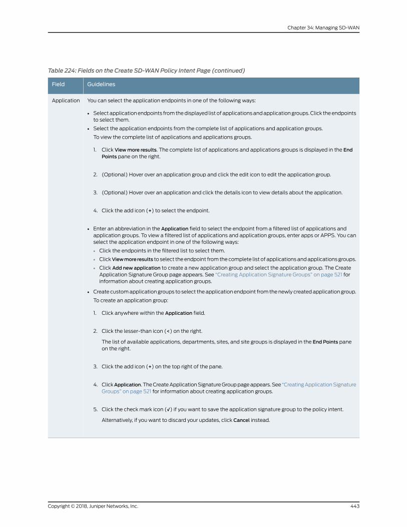
Table 224: Fields on the Create SD-WAN Policy Intent Page (continued)
GuidelinesField
You can select the application endpoints in one of the following ways:
• Selectapplicationendpoints fromthedisplayed listofapplicationsandapplicationgroups.Click theendpointsto select them.
• Select the application endpoints from the complete list of applications and application groups.
To view the complete list of applications and applications groups.
1. Click Viewmore results. The complete list of applications and applications groups is displayed in the EndPoints pane on the right.
2. (Optional) Hover over an application group and click the edit icon to edit the application group.
3. (Optional) Hover over an application and click the details icon to view details about the application.
4. Click the add icon (+) to select the endpoint.
• Enter an abbreviation in the Application field to select the endpoint from a filtered list of applications andapplication groups. To view a filtered list of applications and application groups, enter apps or APPS. You canselect the application endpoint in one of the following ways:
• Click the endpoints in the filtered list to select them.
• ClickViewmore results to select theendpoint fromthecomplete list of applicationsandapplicationsgroups.
• Click Add new application to create a new application group and select the application group. The CreateApplication Signature Group page appears. See “Creating Application Signature Groups” on page 521 forinformation about creating application groups.
• Create customapplicationgroups to select theapplicationendpoint fromthenewly createdapplicationgroup.
To create an application group:
1. Click anywhere within the Application field.
2. Click the lesser-than icon (<) on the right.
The list of available applications, departments, sites, and site groups is displayed in the End Points paneon the right.
3. Click the add icon (+) on the top right of the pane.
4. ClickApplication. TheCreateApplicationSignatureGrouppageappears.See “CreatingApplicationSignatureGroups” on page 521 for information about creating application groups.
5. Click the check mark icon (√) if you want to save the application signature group to the policy intent.
Alternatively, if you want to discard your updates, click Cancel instead.
Application
443Copyright © 2018, Juniper Networks, Inc.
Chapter 34: Managing SD-WAN
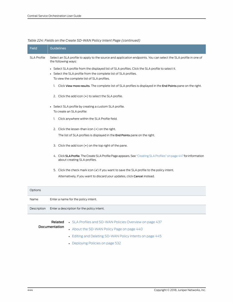
Table 224: Fields on the Create SD-WAN Policy Intent Page (continued)
GuidelinesField
Select an SLA profile to apply to the source and application endpoints. You can select the SLA profile in one ofthe following ways:
• Select SLA profile from the displayed list of SLA profiles. Click the SLA profile to select it.
• Select the SLA profile from the complete list of SLA profiles.
To view the complete list of SLA profiles.
1. Click Viewmore results. The complete list of SLA profiles is displayed in the End Points pane on the right.
2. Click the add icon (+) to select the SLA profile.
• Select SLA profile by creating a custom SLA profile.
To create an SLA profile:
1. Click anywhere within the SLA Profile field.
2. Click the lesser-than icon (<) on the right.
The list of SLA profiles is displayed in the End Points pane on the right.
3. Click the add icon (+) on the top right of the pane.
4. ClickSLAProfile. TheCreateSLAProfilePageappears.See“CreatingSLAProfiles”onpage447 for informationabout creating SLA profiles.
5. Click the check mark icon (√) if you want to save the SLA profile to the policy intent.
Alternatively, if you want to discard your updates, click Cancel instead.
SLA Profile
Options
Enter a name for the policy intent.Name
Enter a description for the policy intent.Description
RelatedDocumentation
SLA Profiles and SD-WAN Policies Overview on page 437•
• About the SD-WAN Policy Page on page 440
• Editing and Deleting SD-WAN Policy Intents on page 445
• Deploying Policies on page 532
Copyright © 2018, Juniper Networks, Inc.444
Contrail Service Orchestration User Guide
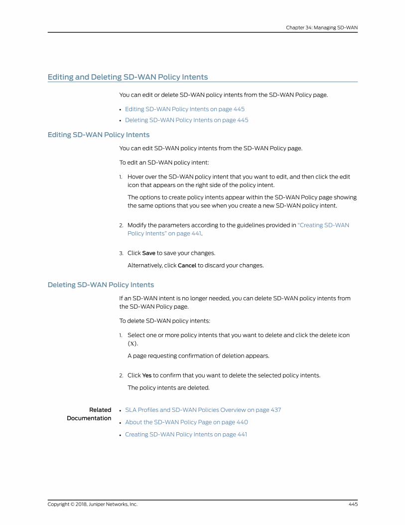
Editing and Deleting SD-WANPolicy Intents
You can edit or delete SD-WAN policy intents from the SD-WAN Policy page.
• Editing SD-WAN Policy Intents on page 445
• Deleting SD-WAN Policy Intents on page 445
Editing SD-WANPolicy Intents
You can edit SD-WAN policy intents from the SD-WAN Policy page.
To edit an SD-WAN policy intent:
1. Hover over the SD-WAN policy intent that you want to edit, and then click the edit
icon that appears on the right side of the policy intent.
The options to create policy intents appear within the SD-WAN Policy page showing
the same options that you see when you create a new SD-WAN policy intent.
2. Modify the parameters according to the guidelines provided in “Creating SD-WAN
Policy Intents” on page 441.
3. Click Save to save your changes.
Alternatively, click Cancel to discard your changes.
Deleting SD-WANPolicy Intents
If an SD-WAN intent is no longer needed, you can delete SD-WAN policy intents from
the SD-WAN Policy page.
To delete SD-WAN policy intents:
1. Select one or more policy intents that you want to delete and click the delete icon
(Χ).
A page requesting confirmation of deletion appears.
2. Click Yes to confirm that you want to delete the selected policy intents.
The policy intents are deleted.
RelatedDocumentation
SLA Profiles and SD-WAN Policies Overview on page 437•
• About the SD-WAN Policy Page on page 440
• Creating SD-WAN Policy Intents on page 441
445Copyright © 2018, Juniper Networks, Inc.
Chapter 34: Managing SD-WAN
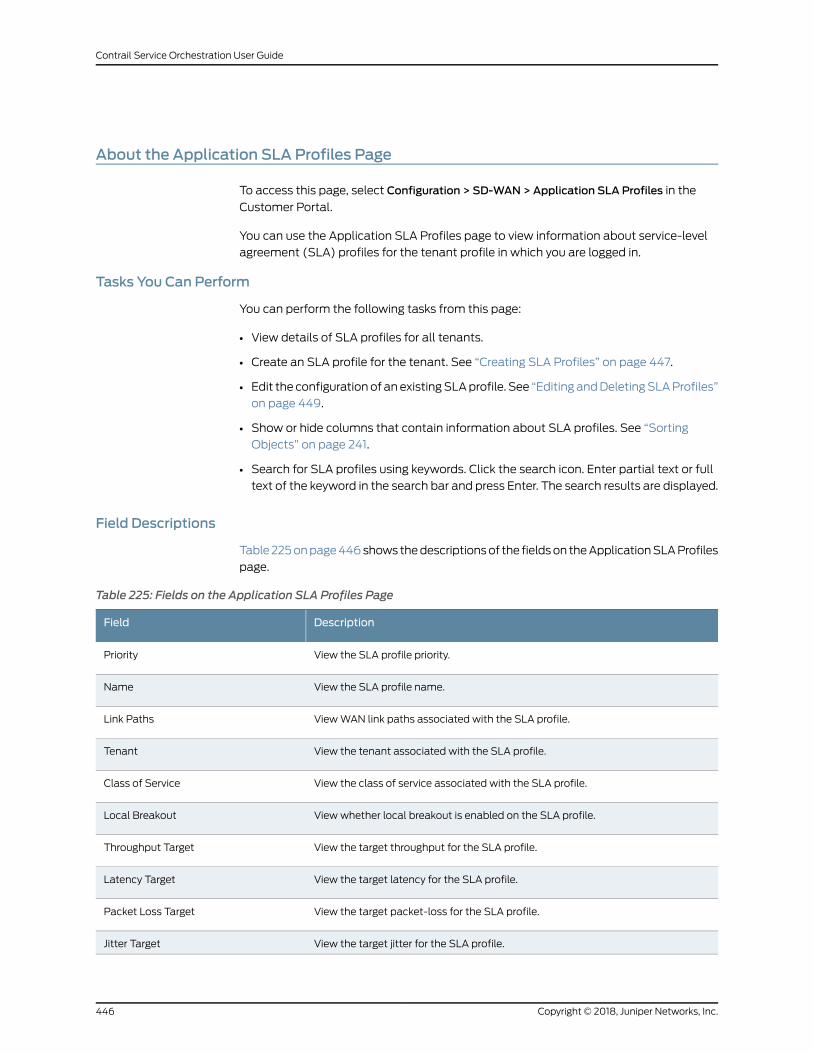
About the Application SLA Profiles Page
To access this page, select Configuration > SD-WAN>Application SLA Profiles in the
Customer Portal.
You can use the Application SLA Profiles page to view information about service-level
agreement (SLA) profiles for the tenant profile in which you are logged in.
Tasks You Can Perform
You can perform the following tasks from this page:
• View details of SLA profiles for all tenants.
• Create an SLA profile for the tenant. See “Creating SLA Profiles” on page 447.
• Edit the configurationof anexistingSLAprofile. See “Editing andDeletingSLAProfiles”
on page 449.
• Show or hide columns that contain information about SLA profiles. See “Sorting
Objects” on page 241.
• Search for SLA profiles using keywords. Click the search icon. Enter partial text or full
text of the keyword in the search bar and press Enter. The search results are displayed.
Field Descriptions
Table225onpage446shows thedescriptionsof the fieldson theApplicationSLAProfiles
page.
Table 225: Fields on the Application SLA Profiles Page
DescriptionField
View the SLA profile priority.Priority
View the SLA profile name.Name
ViewWAN link paths associated with the SLA profile.Link Paths
View the tenant associated with the SLA profile.Tenant
View the class of service associated with the SLA profile.Class of Service
Viewwhether local breakout is enabled on the SLA profile.Local Breakout
View the target throughput for the SLA profile.Throughput Target
View the target latency for the SLA profile.Latency Target
View the target packet-loss for the SLA profile.Packet Loss Target
View the target jitter for the SLA profile.Jitter Target
Copyright © 2018, Juniper Networks, Inc.446
Contrail Service Orchestration User Guide
Table 225: Fields on the Application SLA Profiles Page (continued)
DescriptionField
View the target delay for the SLA profile.
Target delay is calculated as two times the target latency.
Delay Target
RelatedDocumentation
SLA Profiles and SD-WAN Policies Overview on page 437•
• Local Breakout Overview on page 537
• Creating SLA Profiles on page 447
• Editing and Deleting SLA Profiles on page 449
Creating SLA Profiles
You can use the Create SLA Profile page to create a new service-level agreement (SLA)
profile for the current tenant and configure target metrics for the SLA profile.
To add an SLA Profile to the tenant:
1. Click the add icon (+) on the Configuration > Application SLA Profiles page in the
Customer Portal.
The Create SLA Profile page appears.
2. Enter the general SLA profile information according to the guidelines provided in
Table 226 on page 447.
3. ClickOK to create the SLA profile. The Application SLA Profile page appears with the
new SLA profile information.
Alternatively, if you want to discard your updates, click Cancel instead.
Table 226: Fields on the Create SLA Profile page
GuidelinesField
General
Enter a name for the SLA profile.
Can be a unique string of not more than 15 characters that contains alphanumeric charactersand hyphen (-).
Name
SLA Configuration
Choose a traffic type profile to apply the class-of-service configuration and priority to the SLAprofile. You can select a traffic type profile only when it is in the Enabled state.
Traffic Type Profile
447Copyright © 2018, Juniper Networks, Inc.
Chapter 34: Managing SD-WAN
Table 226: Fields on the Create SLA Profile page (continued)
GuidelinesField
Enable local breakout for theSLAprofile. Local breakout is theability of the site to route Internettraffic directly from the site.
Local Breakout
Select the preferredWAN link type to associate with the SLA profile. The options are Any,MPLS, and Internet. Any is the default value. For SLA profiles that are used for local breakout,youmust select a path preference. For SLA profiles that are not used for local breakout, youmust select a path preference or configure at least one SLA parameter.
Path Preference
Enable failover to switch links when the active links fail tomeet the SLA criteria. In such cases,the traffic is routed to links that meet SLA criteria. Failover is supported only for MPLS orInternet links.
NOTE: The Failover option is supported only for bandwidth-optimized SD-WAN networks.
Failover
Choose one of the following options:
• Does notmeet one ormore SLA parameters—This triggers the path failover if any of the SLAparameters is violated.
• Does notmeet all SLA parameters—This triggers the path failover only when all the SLAparameters are violated.
Path Failover Criteria
SLA Parameters
Enter the target throughput (in Mbps) for the SLA profile. Throughput is the amount of datathat is sent upstream and received downstream by the site during the selected time period.
Throughput
Enter the target latency (inms) for theSLAprofile. Latency is the amount of time that a packetof data takes to travel from one designated point to another. Target delay is calculated as twotimes the target latency.
Latency
Enter the target packet loss (in%) for the SLA profile. Packet loss is the percentage of datapackets dropped by the network to manage congestion.
Packet Loss
Enter the target jitter (inms) for the SLA profile. Jitter is the difference between themaximumandminimum round-trip times of a packet of data.
Jitter
Advanced Configuration–SLA Sampling
Specify the matching percentage of sessions for which you want to run the passive probes.Session-sampling%
Specify the number of SLA violations after which you want CSO to switch paths. The range is1 through 32.
SLA-violation-count
Specify the sampling period, in milliseconds, for which the SLA violations are counted. Therange is 2000 through 60000.
Sampling-period
Specify thewaiting period, inmilliseconds, only afterwhich youwant the link switch to happenif an active link comes back online. This parameter helps prevent frequent switching of trafficbetween active and backup links. The range is 5 through 300.
Switch-cool-off-period
Advanced Configuration-Rate Limiting
Copyright © 2018, Juniper Networks, Inc.448
Contrail Service Orchestration User Guide
Table 226: Fields on the Create SLA Profile page (continued)
GuidelinesField
Enter themaximumupstreamrate (inKbps) for all applicationsassociatedwith theSLAprofile.The rate is in the range 64 through 10,485,760 Kbps.
MaximumUpstream Rate
Enter the maximum burst size (in bytes). The burst size is in the range 1 through 1,342,177,280bytes.
MaximumUpstream BurstSize
Enter the maximum downstream rate (in Kbps) for all applications associated with the SLAprofile. The rate is in the range 64 through 10,485,760 Kbps.
MaximumDownstream Rate
Enter the maximum burst size (in bytes). The burst size is in the range 1 through 1,342,177,280bytes.
MaximumDownstream BurstSize
Select a loss priority based on which packets can be dropped or retained when networkcongestion occurs. The chances of a packet getting dropped is the highest when the losspriority is set to High. Other available values areMediumHigh,Medium Low, and Low.
Loss Priority
NOTE: You can also create SLA profiles from the Configuration > SD-WAN>
SD-WANPolicies page in the Customer Portal.
RelatedDocumentation
SLA Profiles and SD-WAN Policies Overview on page 437•
• About the Application SLA Profiles Page on page 446
• Editing and Deleting SLA Profiles on page 449
Editing and Deleting SLA Profiles
You can use the Applications SLA Profiles page to edit and delete SLA profiles.
• Editing an SLA Profile on page 449
• Deleting SLA Profiles on page 450
Editing an SLA Profile
To edit an SLA Profile:
1. Select the check box for the SLA profile that you want to edit, and click the Edit icon
on the Configuration > Application SLA Profiles page in the Customer Portal.
The Edit Application SLA Profile page appears.
2. Update the general SLA profile information as needed according to the guidelines
provided in “CreatingSLAProfiles” onpage447. Youcannot edit theSLAprofile name.
3. Click Next.
449Copyright © 2018, Juniper Networks, Inc.
Chapter 34: Managing SD-WAN
The Configuration tab appears.
4. Update the configuration parameters as needed according to the guidelines provided
in “Creating SLA Profiles” on page 447.
5. ClickOK to save the updated SLA profile configuration.
TheSLAprofile information that you updatedappears on theApplicationSLAProfiles
page.
Deleting SLA Profiles
You can delete the SLA profile if it is no longer needed. To delete an SLA profile:
1. Select the check box for the SLA profile that you want to delete and click the delete
icon (Χ) on the Configuration > Application SLA Profiles page in the Customer Portal.You can also select multiple SLA profiles.
A page requesting confirmation for the deletion appears.
2. Click Yes to confirm that you want to delete the SLA profile.
The SLA profile is deleted.
RelatedDocumentation
• SLA Profiles and SD-WAN Policies Overview on page 437
• About the Application SLA Profiles Page on page 446
• Creating SLA Profiles on page 447
Copyright © 2018, Juniper Networks, Inc.450
Contrail Service Orchestration User Guide
CHAPTER 35
Managing NAT Policies
• NAT Policies Overview on page 452
• About the NAT Policies Page on page 454
• Creating NAT Policies on page 455
• Editing and Deleting NAT Policies on page 457
• About the Single NAT Policy Page on page 458
• Creating NAT Policy Rules on page 460
• Editing, Cloning, and Deleting NAT Policy Rules on page 466
• Deploying NAT Policy Rules on page 467
• Selecting NAT Source on page 468
• Selecting NAT Destination on page 471
• NAT Pools Overview on page 475
• About the NAT Pools Page on page 476
• Creating NAT Pools on page 477
• Editing, Cloning, and Deleting NAT Pools on page 479
451Copyright © 2018, Juniper Networks, Inc.
NAT Policies Overview
Network Address Translation (NAT) is a form of network masquerading where you can
hidedevicesor sitesbetweenzonesor interfaces.A trusted zone is a segmentofanetwork
on which security measures are applied. It is usually assigned to the internal LAN. An
exampleofanuntrustedzone is the internet.NATmodifies the IPaddressesof thepackets
moving between the trusted and untrusted zones.
Whenever a packet exits a NAT device (when traversing from the internal LAN to the
externalWAN), the device performs a translation on the packet’s IP address by rewriting
it with an IP address that was specified for external use. After translation, the packet
appears to have originated from the gateway rather than from the original device within
the network. This process hides your internal IP addresses from the other networks and
keeps your network secure.
Using NAT also enables you to usemore internal IP addresses. As these IP addresses are
hidden, there is no risk of conflict with an IP address from a different network. This helps
you conserve IP addresses.
CSO supports three types of NAT:
• Source NAT— Translates the source IP address of a packet leaving a trust zone
(outbound traffic). It translates the traffic originating from the device in the trust zone.
The source IP address of the traffic (which is a private IP address), is translated to a
public IP address that can be accessed by the destination device specified in the NAT
rule. The destination IP address is not translated.
The following uses cases show the support for source NAT translation between IPv6
and IPv4 address domains:
• Translation from one IPv6 subnet to another IPv6 subnet without Network Address
Port Translation (NAPT), also known as Port Address Translation (PAT).
• Translation from IPv4addresses to IPv6prefixesalongwith IPv4address translation.
• Translation from IPv6 hosts to IPv6 hosts with or without NAPT.
• Translation from IPv6 hosts to IPv4 hosts with or without NAPT.
• Translation from IPv4 hosts to IPv6 hosts with or without NAPT.
• Destination NAT—Translates the destination IP address of a packet. Using destination
NAT, an external device can send packets to a hidden internal device. As an example,
consider the caseof awebserver behindaNATdevice. Traffic to theWAN-facingpublic
IP address (the destination IP address) is translated to the internal webserver private
IP address.
The following uses cases show the support for destination NAT translation between
IPv6 and IPv4 address domains:
• Mapping of one IPv6 subnet to another IPv6 subnet
• Mapping between one IPv6 host and another IPv6 host
Copyright © 2018, Juniper Networks, Inc.452
Contrail Service Orchestration User Guide
• Mapping of one IPv6 host (and optional port number) to another special IPv6 host
(and optional port number)
• Mapping of one IPv6 host (and optional port number) to another special IPv4 host
(and optional port number)
• Mapping of one IPv4 host (and optional port number) to another special IPv6 host
(and optional port number)
• Static NAT— Always translates a private IP address to the same public IP address. It
translates traffic from both sides of the network (both source and destination). For
example, a web-server with a private IP address can access the Internet using a static,
one-to-one address translation. In this case, outgoing traffic from the web-server
undergoes source NAT translation, and incoming traffic to the web-server undergoes
destination NAT translation.
The following uses cases show the support for static NAT translation between IPv6
and IPv4 address domains:
• Mapping of one IPv6 subnet to another IPv6 subnet.
• Mapping between one IPv6 host and another IPv6 host.
• Mapping between IPv4 address a.b.c.d and IPv6 address Prefix::a.b.c.d.
• Mapping between IPv4 hosts and IPv6 hosts.
• Mapping between IPv6 hosts and IPv4 hosts.
CSO also supports persistent NAT where address translations are maintained in the
database for a configurable amount of time after a session ends.
Table 227 on page 453 shows the persistent NAT support for different source NAT and
destination NAT addresses.
Table 227: Persistent NAT Support
Persistent NAT
Destination NAT
AddressTranslated AddressSource NAT Address
NoIPv4IPv6IPv4
NoIPv6IPv6IPv4
YesIPv4IPv4IPv6
NoIPv6IPv6IPv6
Table 228 on page 454 and Table 229 on page 454 show the translated address pool
selection for source NAT, destination NAT, and static NAT addresses.
453Copyright © 2018, Juniper Networks, Inc.
Chapter 35: Managing NAT Policies
Table 228: Translated Address Pool Selection for Source NAT
Pool AddressDestination AddressSource NAT Address
IPv4IPv4IPv4
IPv6IPv6 - Subnet must be greater than 96IPv4
IPv4IPv4IPv6
IPv6IPv6IPv6
Table 229: Translated Address Pool Selection for Destination NAT And Static NAT
Pool AddressDestination AddressSource NAT Address
IPv4 or IPv6IPv4IPv4
IPv4 or IPv6IPv6 - Subnet must be greater than 96IPv4
IPv4IPv4IPv6
IPv4 or IPv6IPv6IPv6
NOTE:
• For source NAT, the proxy Neighbor Discovery Protocol (NDP) is availablefor NAT pool addresses. For destination NAT and static NAT, the proxyNDP is available for destination NAT addresses.
• A NAT pool can have a single IPv6 subnet or multiple IPv6 hosts.
• You cannot configure the overflow pool if the address type is IPv6.
• NAT pools permit address entries of only one version type: IPv4 or IPv6.
RelatedDocumentation
About the NAT Policies Page on page 454•
• Creating NAT Policies on page 455
• Editing and Deleting NAT Policies on page 457
• Editing, Cloning, and Deleting NAT Policy Rules on page 466
About the NAT Policies Page
To access this page, select Configuration > NAT > NAT Policies.
Use the NAT Policies page to create, modify, clone, and delete NAT policies and policy
rules. You can filter and sort this information to get a better understanding of what you
want to configure.
Copyright © 2018, Juniper Networks, Inc.454
Contrail Service Orchestration User Guide
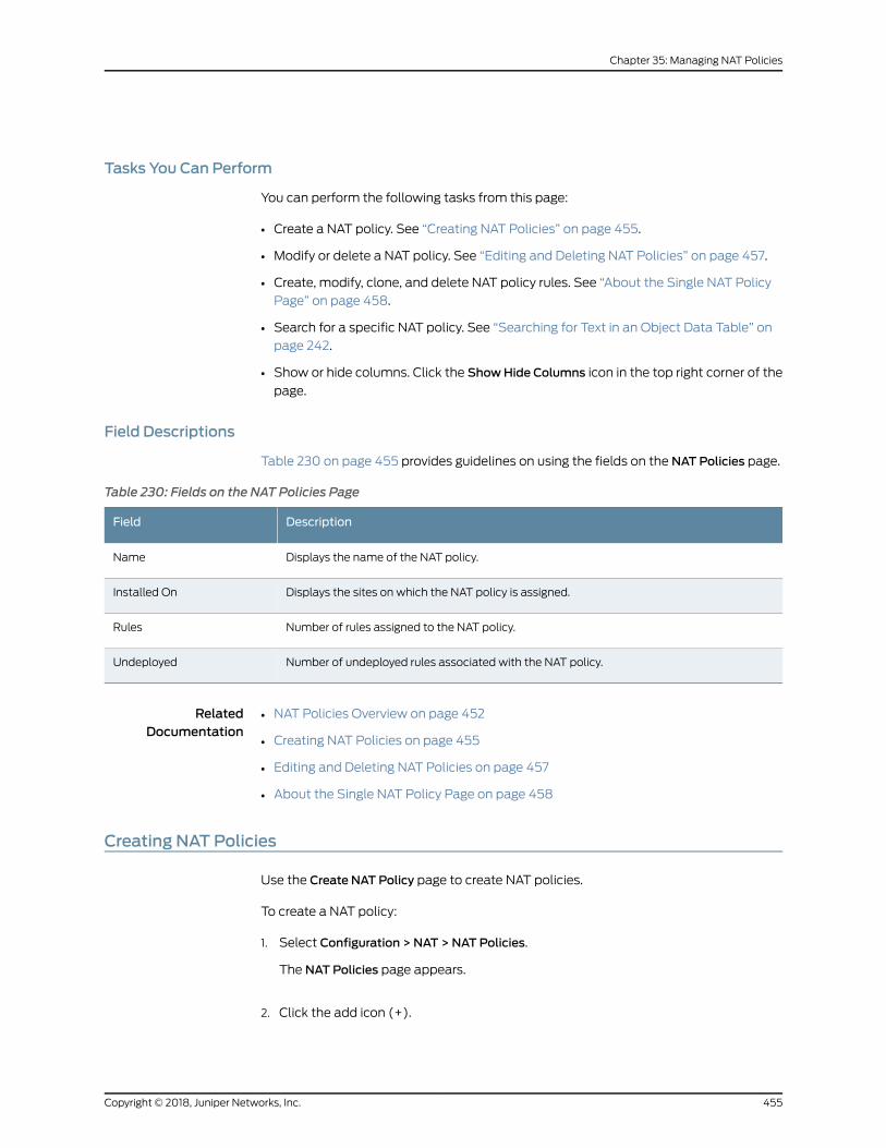
Tasks You Can Perform
You can perform the following tasks from this page:
• Create a NAT policy. See “Creating NAT Policies” on page 455.
• Modify or delete a NAT policy. See “Editing and Deleting NAT Policies” on page 457.
• Create, modify, clone, and delete NAT policy rules. See “About the Single NAT Policy
Page” on page 458.
• Search for a specific NAT policy. See “Searching for Text in an Object Data Table” on
page 242.
• Show or hide columns. Click the ShowHide Columns icon in the top right corner of the
page.
Field Descriptions
Table 230 on page 455 provides guidelines on using the fields on the NAT Policies page.
Table 230: Fields on the NAT Policies Page
DescriptionField
Displays the name of the NAT policy.Name
Displays the sites on which the NAT policy is assigned.Installed On
Number of rules assigned to the NAT policy.Rules
Number of undeployed rules associated with the NAT policy.Undeployed
RelatedDocumentation
NAT Policies Overview on page 452•
• Creating NAT Policies on page 455
• Editing and Deleting NAT Policies on page 457
• About the Single NAT Policy Page on page 458
Creating NAT Policies
Use the Create NAT Policy page to create NAT policies.
To create a NAT policy:
1. Select Configuration > NAT >NAT Policies.
The NAT Policies page appears.
2. Click the add icon (+).
455Copyright © 2018, Juniper Networks, Inc.
Chapter 35: Managing NAT Policies
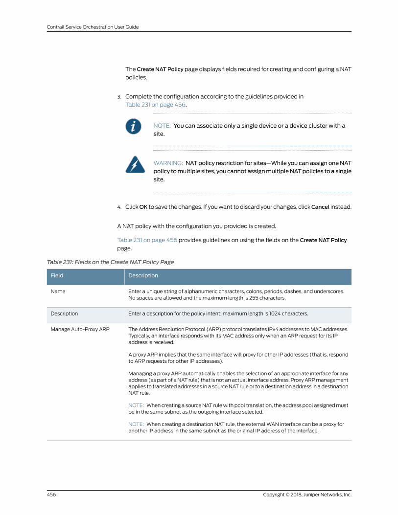
TheCreateNATPolicy page displays fields required for creating and configuring a NAT
policies.
3. Complete the configuration according to the guidelines provided in
Table 231 on page 456.
NOTE: You can associate only a single device or a device cluster with asite.
WARNING: NATpolicy restriction for sites—While you can assign oneNATpolicy tomultiple sites, youcannotassignmultipleNATpolicies toa singlesite.
4. ClickOK to save the changes. If youwant todiscard your changes, clickCancel instead.
A NAT policy with the configuration you provided is created.
Table 231 on page 456 provides guidelines on using the fields on the Create NAT Policy
page.
Table 231: Fields on the Create NAT Policy Page
DescriptionField
Enter a unique string of alphanumeric characters, colons, periods, dashes, and underscores.No spaces are allowed and themaximum length is 255 characters.
Name
Enter a description for the policy intent; maximum length is 1024 characters.Description
TheAddress ResolutionProtocol (ARP) protocol translates IPv4 addresses toMACaddresses.Typically, an interface responds with its MAC address only when an ARP request for its IPaddress is received.
A proxy ARP implies that the same interface will proxy for other IP addresses (that is, respondto ARP requests for other IP addresses).
Managing a proxy ARP automatically enables the selection of an appropriate interface for anyaddress (aspart of aNAT rule) that is not anactual interfaceaddress. ProxyARPmanagementapplies to translatedaddresses in a sourceNAT rule or to adestination address in adestinationNAT rule.
NOTE: Whencreating a sourceNAT rulewith pool translation, the address pool assignedmustbe in the same subnet as the outgoing interface selected.
NOTE: When creating a destination NAT rule, the external WAN interface can be a proxy foranother IP address in the same subnet as the original IP address of the interface.
Manage Auto-Proxy ARP
Copyright © 2018, Juniper Networks, Inc.456
Contrail Service Orchestration User Guide
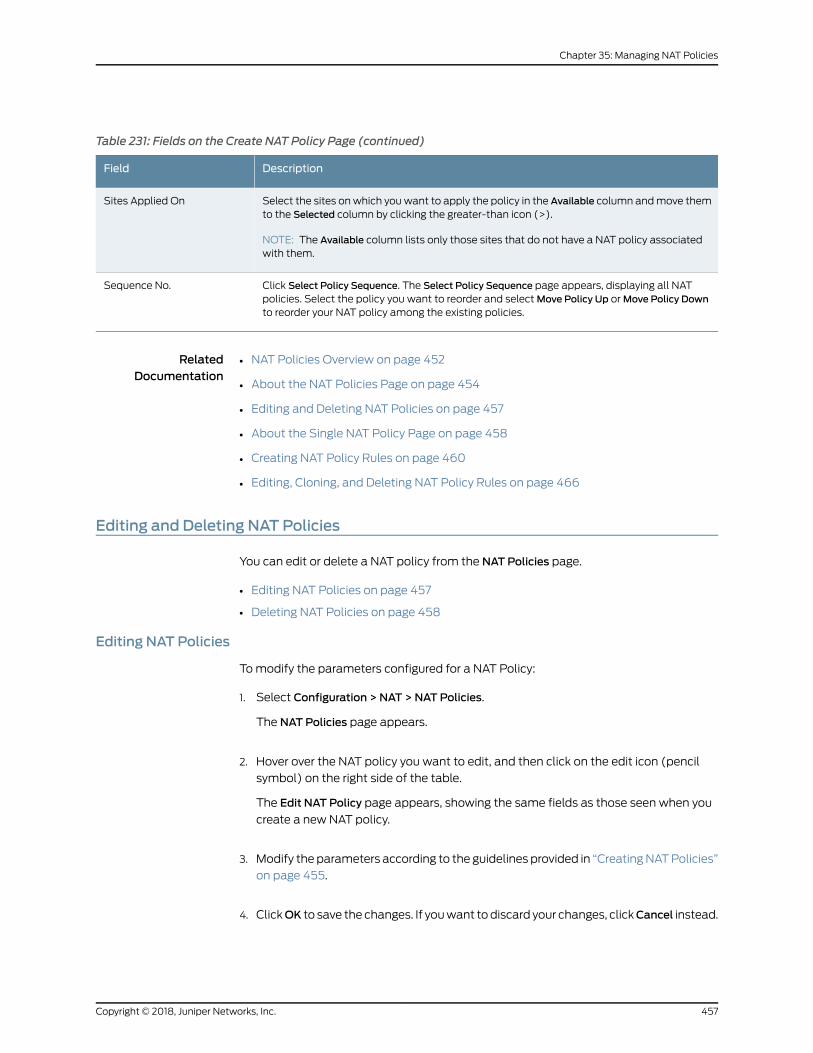
Table 231: Fields on the Create NAT Policy Page (continued)
DescriptionField
Select the sites onwhich youwant to apply the policy in the Available column andmove themto the Selected column by clicking the greater-than icon (>).
NOTE: The Available column lists only those sites that do not have a NAT policy associatedwith them.
Sites Applied On
Click Select Policy Sequence. The Select Policy Sequence page appears, displaying all NATpolicies. Select the policy you want to reorder and selectMove Policy Up orMove Policy Downto reorder your NAT policy among the existing policies.
Sequence No.
RelatedDocumentation
NAT Policies Overview on page 452•
• About the NAT Policies Page on page 454
• Editing and Deleting NAT Policies on page 457
• About the Single NAT Policy Page on page 458
• Creating NAT Policy Rules on page 460
• Editing, Cloning, and Deleting NAT Policy Rules on page 466
Editing and Deleting NAT Policies
You can edit or delete a NAT policy from the NAT Policies page.
• Editing NAT Policies on page 457
• Deleting NAT Policies on page 458
Editing NAT Policies
Tomodify the parameters configured for a NAT Policy:
1. Select Configuration > NAT >NAT Policies.
The NAT Policies page appears.
2. Hover over the NAT policy you want to edit, and then click on the edit icon (pencil
symbol) on the right side of the table.
The Edit NAT Policy page appears, showing the same fields as those seen when you
create a new NAT policy.
3. Modify the parameters according to the guidelines provided in “CreatingNATPolicies”
on page 455.
4. ClickOK to save the changes. If youwant todiscard your changes, clickCancel instead.
457Copyright © 2018, Juniper Networks, Inc.
Chapter 35: Managing NAT Policies
If you clickOK, you will see the modified NAT policy in the NAT Policies page.
Deleting NAT Policies
To delete a NAT policy:
1. Select Configuration > NAT >NAT Policies.
The NAT Policies page appears.
2. Hover over the NAT policy you want to delete and then click the delete icon (X) .
An alert message appears, verifying that you want to delete your selection.
3. Click Yes to delete the selection. If you do not want to delete, click Cancel instead.
If you click Yes, the NAT policy is deleted.
NOTE: When the NAT policy is deleted, the NAT rules associated with thepolicy are deleted from device.
RelatedDocumentation
NAT Policies Overview on page 452•
• About the NAT Policies Page on page 454
• Creating NAT Policies on page 455
• Editing, Cloning, and Deleting NAT Policy Rules on page 466
About the Single NAT Policy Page
To access this page, select Configuration > NAT > NAT Policies. The NAT Policies page
appears displaying all existing NAT policies. Click on a NAT policy to view the rules
associated with it.
The Single NAT Policy page displays the NAT rules associated with the NAT policy, and
keep track of the number and order of rules for each policy. You can also create a new
NAT rule, modify the configured parameters of existing NAT rules, clone, and delete NAT
rules, using this page.
Tasks You Can Perform
You can perform the following tasks from this page:
• Create a NAT rule. See “Creating NAT Policy Rules” on page 460.
• Update the sequenceof theNAT rules using theupanddownarrows that appearwhen
you hover over the NAT rule.
• Modify, clone, and delete NAT rules. See “Editing, Cloning, and Deleting NAT Policy
Rules” on page 466.
Copyright © 2018, Juniper Networks, Inc.458
Contrail Service Orchestration User Guide
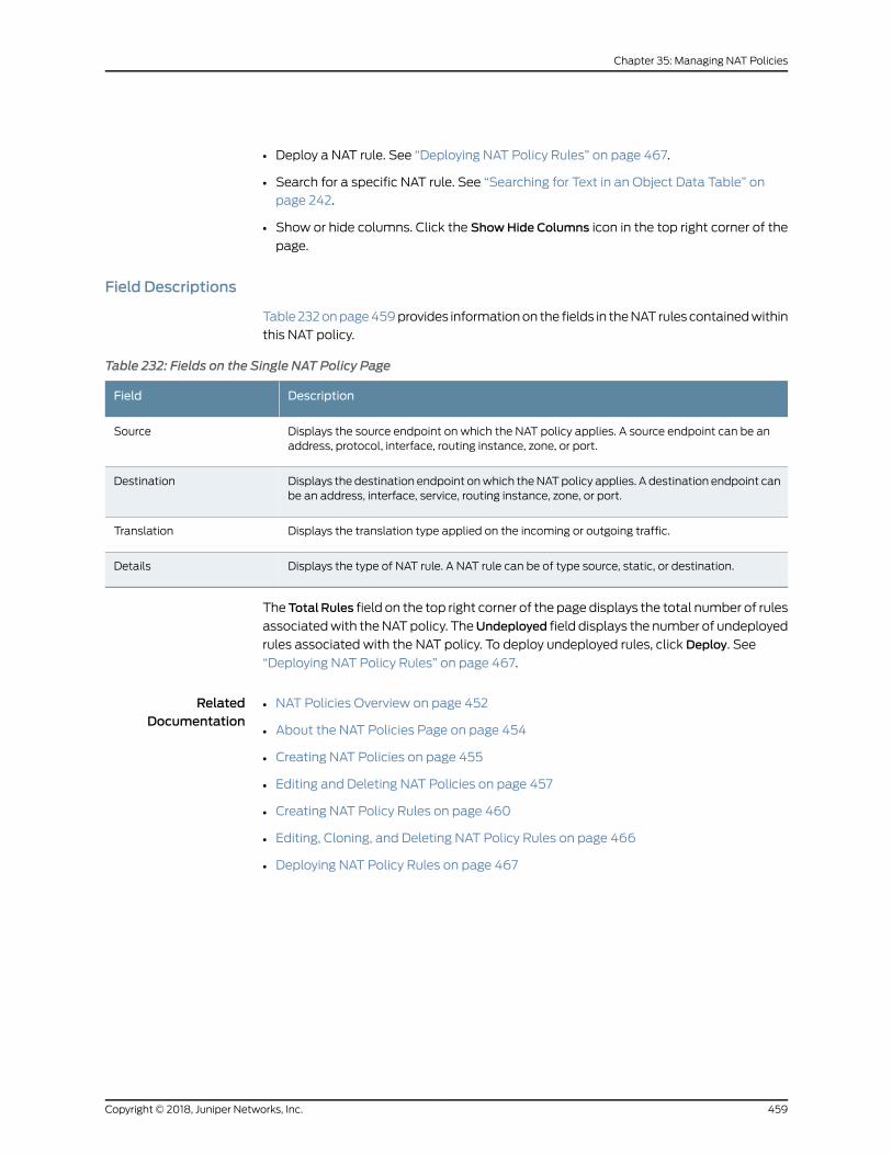
• Deploy a NAT rule. See “Deploying NAT Policy Rules” on page 467.
• Search for a specific NAT rule. See “Searching for Text in an Object Data Table” on
page 242.
• Show or hide columns. Click the ShowHide Columns icon in the top right corner of the
page.
Field Descriptions
Table232onpage459provides informationon the fields in theNAT rules containedwithin
this NAT policy.
Table 232: Fields on the Single NAT Policy Page
DescriptionField
Displays the source endpoint on which the NAT policy applies. A source endpoint can be anaddress, protocol, interface, routing instance, zone, or port.
Source
Displays the destination endpoint onwhich theNATpolicy applies. A destination endpoint canbe an address, interface, service, routing instance, zone, or port.
Destination
Displays the translation type applied on the incoming or outgoing traffic.Translation
Displays the type of NAT rule. A NAT rule can be of type source, static, or destination.Details
TheTotalRules field on the top right corner of the page displays the total number of rules
associatedwith theNATpolicy. TheUndeployed field displays the number of undeployed
rules associated with the NAT policy. To deploy undeployed rules, click Deploy. See
“Deploying NAT Policy Rules” on page 467.
RelatedDocumentation
NAT Policies Overview on page 452•
• About the NAT Policies Page on page 454
• Creating NAT Policies on page 455
• Editing and Deleting NAT Policies on page 457
• Creating NAT Policy Rules on page 460
• Editing, Cloning, and Deleting NAT Policy Rules on page 466
• Deploying NAT Policy Rules on page 467
459Copyright © 2018, Juniper Networks, Inc.
Chapter 35: Managing NAT Policies
Creating NAT Policy Rules
NATprocessingcenterson theevaluationofNAT rule setsand rules.A rule setdetermines
the overall direction of the traffic to be processed. After a rule set thatmatches the traffic
is found, each rule in the rule set is evaluated for a match. NAT rules canmatch on the
following packet information:
• Source and destination address
• Source port (for source and static NAT only)
• Destination port
The first rule in the rule set that matches the traffic is used. If a packet matches a rule in
a rule set during session establishment, traffic is processed according to the action
specified by that rule.
To create a newNAT rule, click theNATpolicy name. TheSingle NATPolicypage appears,
providing your with options to configure NAT rules. Alternately, you can click on the rule
number listed under Rules against the policy, to create a new rule. You can configure the
following types of NAT rules:
• Static—To add a static NAT rule, click Add Static NAT Rule or click Create on the top
right corner and select Static.
• Source—To add a source NAT rule, click Add Source NAT Rule or click Create on the
top right corner and select Source.
• Destination—To add a destination NAT rule, click Add Destination NAT Rule or click
Create on the top right corner and select Destination.
Depending on the type of rule you have chosen, some fields in the rule will not be
applicable. In addition to defining rules between zones and interfaces, you can define
NAT rules with virtual routers defined on the device. These rules can be successfully
published and updated on the device.
To create a NAT policy rule:
1. Select Configuration > NAT >NAT Policies.
The NAT Policies page appears, displayed the existing NAT policies.
2. Click the name of the NAT policy for which you want to create rules. Alternately, you
can click on the number listed under Rules against a NAT policy.
The Single NAT Policy page appears.
3. Click Create and select either Source, Static, or Destination. The page displays fields
for creating a NAT rule.
Copyright © 2018, Juniper Networks, Inc.460
Contrail Service Orchestration User Guide
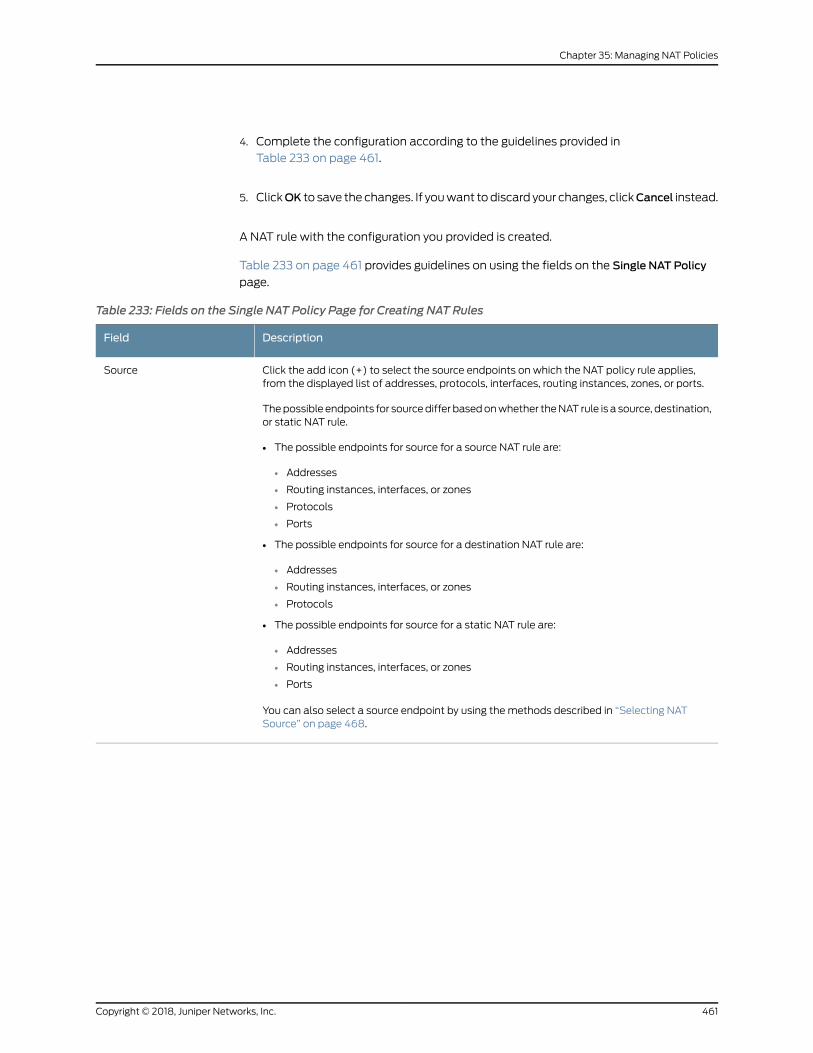
4. Complete the configuration according to the guidelines provided in
Table 233 on page 461.
5. ClickOK to save the changes. If youwant todiscard your changes, clickCancel instead.
A NAT rule with the configuration you provided is created.
Table 233 on page 461 provides guidelines on using the fields on the Single NAT Policy
page.
Table 233: Fields on the Single NAT Policy Page for Creating NAT Rules
DescriptionField
Click the add icon (+) to select the source endpoints on which the NAT policy rule applies,from the displayed list of addresses, protocols, interfaces, routing instances, zones, or ports.
Thepossible endpoints for sourcediffer basedonwhether theNAT rule is a source, destination,or static NAT rule.
• The possible endpoints for source for a source NAT rule are:
• Addresses
• Routing instances, interfaces, or zones
• Protocols
• Ports
• The possible endpoints for source for a destination NAT rule are:
• Addresses
• Routing instances, interfaces, or zones
• Protocols
• The possible endpoints for source for a static NAT rule are:
• Addresses
• Routing instances, interfaces, or zones
• Ports
You can also select a source endpoint by using the methods described in “Selecting NATSource” on page 468.
Source
461Copyright © 2018, Juniper Networks, Inc.
Chapter 35: Managing NAT Policies
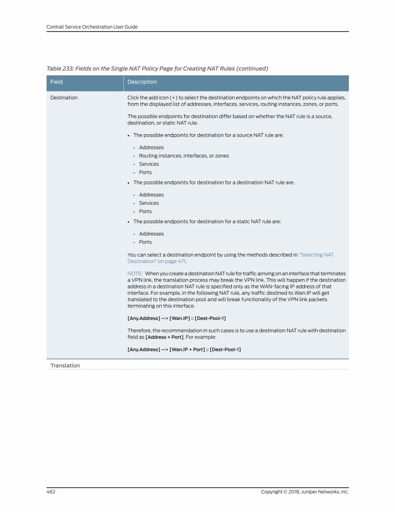
Table 233: Fields on the Single NAT Policy Page for Creating NAT Rules (continued)
DescriptionField
Click the add icon (+) to select the destination endpoints onwhich theNATpolicy rule applies,from the displayed list of addresses, interfaces, services, routing instances, zones, or ports.
The possible endpoints for destination differ based on whether the NAT rule is a source,destination, or static NAT rule.
• The possible endpoints for destination for a source NAT rule are:
• Addresses
• Routing instances, interfaces, or zones
• Services
• Ports
• The possible endpoints for destination for a destination NAT rule are:
• Addresses
• Services
• Ports
• The possible endpoints for destination for a static NAT rule are:
• Addresses
• Ports
You can select a destination endpoint by using the methods described in “Selecting NATDestination” on page 471.
NOTE: WhenyoucreateadestinationNAT rule for trafficarrivingonan interface that terminatesa VPN link, the translation process may break the VPN link. This will happen if the destinationaddress in a destination NAT rule is specified only as theWAN-facing IP address of thatinterface. For example, in the following NAT rule, any traffic destined toWan.IP will gettranslated to the destination pool and will break functionality of the VPN link packetsterminating on this interface.
[Any.Address] --> [Wan.IP] :: [Dest-Pool-1]
Therefore, the recommendation in such cases is to use a destination NAT rulewith destinationfield as [Address + Port]. For example:
[Any.Address] --> [Wan.IP + Port] :: [Dest-Pool-1]
Destination
Translation
Copyright © 2018, Juniper Networks, Inc.462
Contrail Service Orchestration User Guide
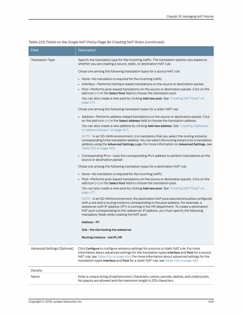
Table 233: Fields on the Single NAT Policy Page for Creating NAT Rules (continued)
DescriptionField
Specify the translation type for the incoming traffic. The translation options vary based onwhether you are creating a source, static, or destination NAT rule.
Chose one among the following translation types for a source NAT rule:
• None—No translation is required for the incoming traffic.
• Interface—Performs interface-based translations on the source or destination packet.
• Pool—Performs pool-based translations on the source or destination packet. Click on theadd icon (+) in the Select Pool field to choose the translation pool.
You can also create a new pool by clicking Add new pool. See “Creating NAT Pools” onpage 477.
Chose one among the following translation types for a static NAT rule:
• Address—Performs address-based translations on the source or destination packet. Clickon the add icon (+) in the Select Address field to choose the translation address.
You can also create a new address by clicking Add new address. See “Creating Addressesor Address Groups” on page 507.
NOTE: In an SD-WAN environment, it is mandatory that you select the routing instancecorresponding to the translationaddress. Youcanselect the routing instance for a translationaddress using the Advanced Settings page. For more information on Advanced Settings, seeTable 235 on page 465.
• Corresponding IPv4—Uses the corresponding IPv4 address to perform translations on thesource or destination packet.
Chose one among the following translation types for a destination NAT rule:
• None—No translation is required for the incoming traffic.
• Pool—Performs pool-based translations on the source or destination packet. Click on theadd icon (+) in the Select Pool field to choose the translation pool.
You can also create a new pool by clicking Add new pool. See “Creating NAT Pools” onpage 477.
NOTE: In anSD-WANenvironment, thedestinationNATpool selected shouldbeconfiguredwith a site and a routing instance corresponding to the pool address. For example, awebserver with IP address (IP1) is running in the HR department. To create a destinationNAT pool corresponding to this webserver IP address, youmust specify the followingmandatory fields while creating the NAT pool:
Address - IP1
Site - the site hosting the webserver
Routing instance - natVR_HR
Translation Type
Click Configure to configure advance settings for a source or static NAT rule. For moreinformation about advanced settings for the translation types Interface and Pool for a sourceNAT rule, see Table 234 on page 464. For more information about advanced settings for thetranslation types Interface and Pool for a static NAT rule, see Table 235 on page 465
AdvancedSettings(Optional)
Details
Enter a unique string of alphanumeric characters, colons, periods, dashes, and underscores.No spaces are allowed and themaximum length is 255 characters.
Name
463Copyright © 2018, Juniper Networks, Inc.
Chapter 35: Managing NAT Policies
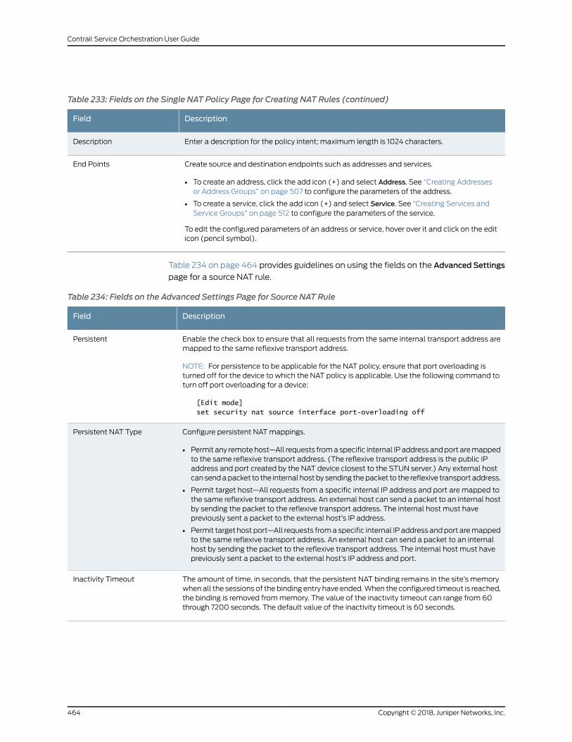
Table 233: Fields on the Single NAT Policy Page for Creating NAT Rules (continued)
DescriptionField
Enter a description for the policy intent; maximum length is 1024 characters.Description
Create source and destination endpoints such as addresses and services.
• To create an address, click the add icon (+) and select Address. See “Creating Addressesor Address Groups” on page 507 to configure the parameters of the address.
• To create a service, click the add icon (+) and select Service. See “Creating Services andService Groups” on page 512 to configure the parameters of the service.
To edit the configured parameters of an address or service, hover over it and click on the editicon (pencil symbol).
End Points
Table 234 on page 464 provides guidelines on using the fields on the Advanced Settings
page for a source NAT rule.
Table 234: Fields on the Advanced Settings Page for Source NAT Rule
DescriptionField
Enable the check box to ensure that all requests from the same internal transport address aremapped to the same reflexive transport address.
NOTE: For persistence to be applicable for the NAT policy, ensure that port overloading isturned off for the device to which the NAT policy is applicable. Use the following command toturn off port overloading for a device:
[Edit mode]set security nat source interface port-overloading off
Persistent
Configure persistent NATmappings.
• Permit any remotehost—All requests fromaspecific internal IPaddressandport aremappedto the same reflexive transport address. (The reflexive transport address is the public IPaddress and port created by the NAT device closest to the STUN server.) Any external hostcansendapacket to the internal hostby sending thepacket to the reflexive transport address.
• Permit target host—All requests from a specific internal IP address and port are mapped tothe same reflexive transport address. An external host can send a packet to an internal hostby sending the packet to the reflexive transport address. The internal host must havepreviously sent a packet to the external host’s IP address.
• Permit target host port—All requests fromaspecific internal IP address andport aremappedto the same reflexive transport address. An external host can send a packet to an internalhost by sending the packet to the reflexive transport address. The internal host must havepreviously sent a packet to the external host’s IP address and port.
Persistent NAT Type
The amount of time, in seconds, that the persistent NAT binding remains in the site’s memorywhenall the sessions of the binding entry have ended.When the configured timeout is reached,the binding is removed frommemory. The value of the inactivity timeout can range from 60through 7200 seconds. The default value of the inactivity timeout is 60 seconds.
Inactivity Timeout
Copyright © 2018, Juniper Networks, Inc.464
Contrail Service Orchestration User Guide
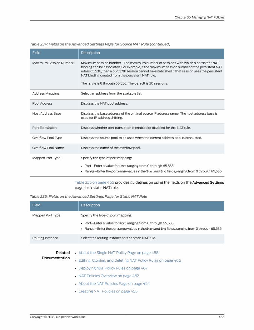
Table 234: Fields on the Advanced Settings Page for Source NAT Rule (continued)
DescriptionField
Maximum session number—Themaximum number of sessions with which a persistent NATbinding can be associated. For example, if themaximum session number of the persistent NATrule is 65,536, then a65,537th session cannot be established if that session uses the persistentNAT binding created from the persistent NAT rule.
The range is 8 through 65,536. The default is 30 sessions.
Maximum Session Number
Select an address from the available list.Address Mapping
Displays the NAT pool address.Pool Address
Displays the base address of the original source IP address range. The host address base isused for IP address shifting.
Host Address Base
Displays whether port translation is enabled or disabled for this NAT rule.Port Translation
Displays the source pool to be used when the current address pool is exhausted.Overflow Pool Type
Displays the name of the overflow pool.Overflow Pool Name
Specify the type of port mapping:
• Port—Enter a value for Port, ranging from 0 through 65,535.
• Range—Enter theport rangevalues in theStartandEnd fields, ranging from0through65,535.
Mapped Port Type
Table 235 on page 465 provides guidelines on using the fields on the Advanced Settings
page for a static NAT rule.
Table 235: Fields on the Advanced Settings Page for Static NAT Rule
DescriptionField
Specify the type of port mapping:
• Port—Enter a value for Port, ranging from 0 through 65,535.
• Range—Enter theport rangevalues in theStartandEnd fields, ranging from0through65,535.
Mapped Port Type
Select the routing instance for the static NAT rule.Routing Instance
RelatedDocumentation
About the Single NAT Policy Page on page 458•
• Editing, Cloning, and Deleting NAT Policy Rules on page 466
• Deploying NAT Policy Rules on page 467
• NAT Policies Overview on page 452
• About the NAT Policies Page on page 454
• Creating NAT Policies on page 455
465Copyright © 2018, Juniper Networks, Inc.
Chapter 35: Managing NAT Policies
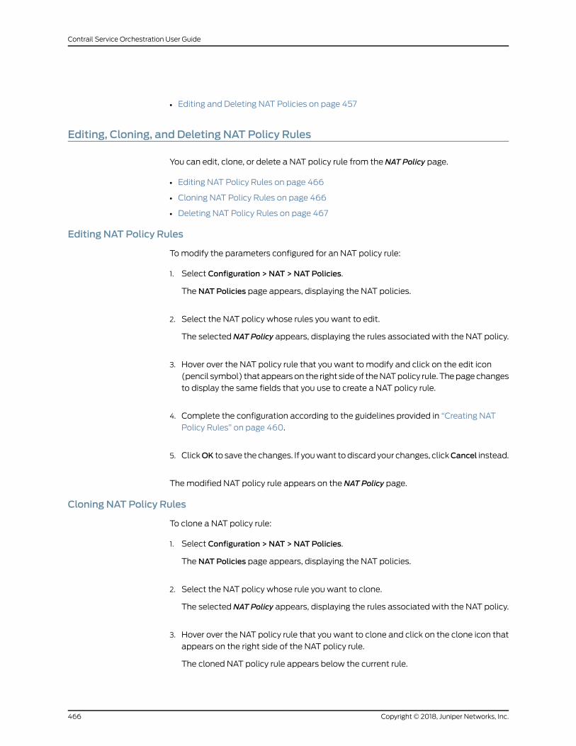
• Editing and Deleting NAT Policies on page 457
Editing, Cloning, and Deleting NAT Policy Rules
You can edit, clone, or delete a NAT policy rule from the NAT Policy page.
• Editing NAT Policy Rules on page 466
• Cloning NAT Policy Rules on page 466
• Deleting NAT Policy Rules on page 467
Editing NAT Policy Rules
Tomodify the parameters configured for an NAT policy rule:
1. Select Configuration > NAT >NAT Policies.
The NAT Policies page appears, displaying the NAT policies.
2. Select the NAT policy whose rules you want to edit.
The selected NAT Policy appears, displaying the rules associated with the NAT policy.
3. Hover over the NAT policy rule that you want to modify and click on the edit icon
(pencil symbol) thatappearson the right sideof theNATpolicy rule. Thepagechanges
to display the same fields that you use to create a NAT policy rule.
4. Complete the configuration according to the guidelines provided in “Creating NAT
Policy Rules” on page 460.
5. ClickOK to save the changes. If youwant todiscard your changes, clickCancel instead.
Themodified NAT policy rule appears on the NAT Policy page.
Cloning NAT Policy Rules
To clone a NAT policy rule:
1. Select Configuration > NAT >NAT Policies.
The NAT Policies page appears, displaying the NAT policies.
2. Select the NAT policy whose rule you want to clone.
The selected NAT Policy appears, displaying the rules associated with the NAT policy.
3. Hover over the NAT policy rule that you want to clone and click on the clone icon that
appears on the right side of the NAT policy rule.
The cloned NAT policy rule appears below the current rule.
Copyright © 2018, Juniper Networks, Inc.466
Contrail Service Orchestration User Guide
You canmodify the parameters configured for the cloned NAT policy rule or rename it
as required.
Deleting NAT Policy Rules
To delete a NAT policy rule:
1. Select Configuration > NAT >NAT Policies.
The NAT Policies page appears, displaying the NAT policies.
2. Select the NAT policy whose rule you want to delete.
The selected NAT Policy appears, displaying the rules associated with the NAT policy.
3. Hover over the NAT policy rule you want to delete and then click the delete icon (X)
.
An alert message appears, verifying that you want to delete your selection.
4. Click Yes to delete the selection. If you do not want to delete, click Cancel instead.
If you click Yes, the selected NAT policy rule is deleted.
RelatedDocumentation
About the Single NAT Policy Page on page 458•
• Creating NAT Policy Rules on page 460
• Deploying NAT Policy Rules on page 467
• NAT Policies Overview on page 452
• About the NAT Policies Page on page 454
• Creating NAT Policies on page 455
• Editing and Deleting NAT Policies on page 457
Deploying NAT Policy Rules
To deploy an NAT policy rule:
1. Select Configuration > NAT Policy > Policies.
2. Click on the name of the NAT policy rules displayed.
The NAT policy rule page appears.
3. Select the NAT policy rule you want to deploy and then click Deploy.
467Copyright © 2018, Juniper Networks, Inc.
Chapter 35: Managing NAT Policies
The Deploy page appears.
4. Configure your deployment as required. See “Deploying Policies” on page 532.
RelatedDocumentation
About the Single NAT Policy Page on page 458•
• Creating NAT Policy Rules on page 460
• Editing, Cloning, and Deleting NAT Policy Rules on page 466
• NAT Policies Overview on page 452
• About the NAT Policies Page on page 454
• Creating NAT Policies on page 455
• Editing and Deleting NAT Policies on page 457
Selecting NAT Source
The following procedures provides various methods using which you can choose an
endpoint as a NAT source:
• Adding an Endpoint as NAT Source on page 468
• Selecting Interfaces when GWR Resides Inside an NFX Box on page 469
• Selecting NAT Source Using Abbreviations on page 469
• Selecting a NAT Source from the End Points Panel on page 470
• Creating and Selecting a NAT Source from the End Points Panel on page 470
• Creating Addresses from Source Field on page 471
Adding an Endpoint as NAT Source
View and select the source endpoint from the complete list of addresses, protocols,
interfaces, zones, routing instances, or ports.
1. Click the Source field. A list of relevant endpoints are displayed.
2. Click the Viewmore results link provided at the bottom of the source endpoints. The
complete list of addresses, protocols, interfaces, and ports is displayed in the End
Points panel on the right.
3. (Optional) Click the edit icon to edit the address, protocol, interface, zones, routing
instances, or port endpoint.
4. Click check mark icon (√) to select the endpoint as a source.
Copyright © 2018, Juniper Networks, Inc.468
Contrail Service Orchestration User Guide
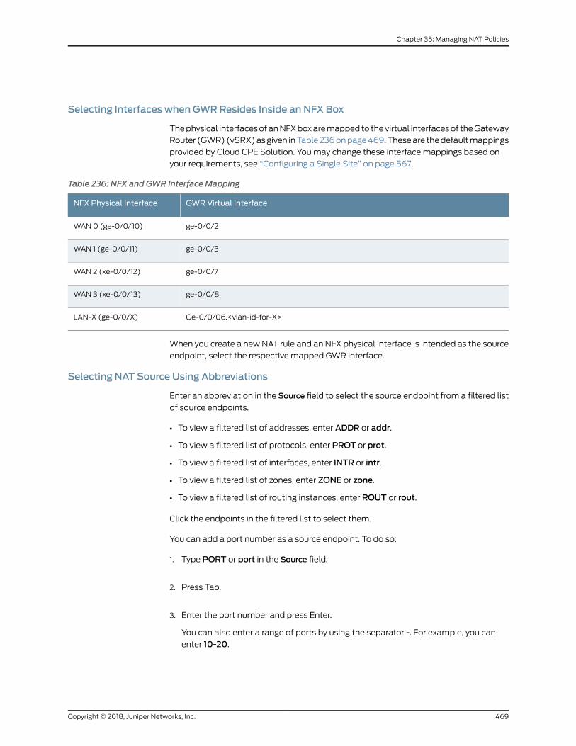
Selecting Interfaces when GWRResides Inside an NFX Box
Thephysical interfacesofanNFXboxaremapped to thevirtual interfacesof theGateway
Router (GWR)(vSRX)asgiven inTable236onpage469.Theseare thedefaultmappings
provided by Cloud CPE Solution. Youmay change these interface mappings based on
your requirements, see “Configuring a Single Site” on page 567.
Table 236: NFX and GWR Interface Mapping
GWRVirtual InterfaceNFX Physical Interface
ge-0/0/2WAN 0 (ge-0/0/10)
ge-0/0/3WAN 1 (ge-0/0/11)
ge-0/0/7WAN 2 (xe-0/0/12)
ge-0/0/8WAN 3 (xe-0/0/13)
Ge-0/0/06.<vlan-id-for-X>LAN-X (ge-0/0/X)
When you create a newNAT rule and an NFX physical interface is intended as the source
endpoint, select the respective mapped GWR interface.
Selecting NAT Source Using Abbreviations
Enter an abbreviation in the Source field to select the source endpoint from a filtered list
of source endpoints.
• To view a filtered list of addresses, enter ADDR or addr.
• To view a filtered list of protocols, enter PROT or prot.
• To view a filtered list of interfaces, enter INTR or intr.
• To view a filtered list of zones, enter ZONE or zone.
• To view a filtered list of routing instances, enter ROUT or rout.
Click the endpoints in the filtered list to select them.
You can add a port number as a source endpoint. To do so:
1. Type PORT or port in the Source field.
2. Press Tab.
3. Enter the port number and press Enter.
You can also enter a range of ports by using the separator -. For example, you canenter 10-20.
469Copyright © 2018, Juniper Networks, Inc.
Chapter 35: Managing NAT Policies
The entered port value is selected as a source endpoint.
Youcanalsoselect theendpoint fromthecomplete list ofaddresses, protocols, interfaces,
zones, and routing instances. See “Adding an Endpoint as NAT Source” on page 468.
Selecting a NAT Source from the End Points Panel
You can select a NAT source endpoint from the End Points panel. Alternately, you can
createanewNATsourceendpoint fromtheEndPointspanel, see “CreatingandSelecting
a NAT Source from the End Points Panel” on page 470.
To select an NAT source endpoint from the End Points panel:
1. Click the Source field.
2. Click the lesser-than icon (<) on the right.
The End Points panel appears, displaying the list of available addresses, interfaces,
protocols, zones, and routing instances.
3. (Optional) To viewmore information about a source endpoint, click the details icon
on the right of the endpoint. To edit the source endpoint, click the edit icon (pencil
symbol) on the right of the endpoint.
NOTE: You can only edit or view details of a source endpoint if theseoptions appear on right side of the endpoint when you hover over it. Notall endpoints provide these options.
4. Click the check mark icon (√) to add the endpoint as a source.
Creating and Selecting a NAT Source from the End Points Panel
To create a new source endpoint from the End Points panel:
1. Click the add icon (+) on the top right of the panel and select the type of endpoint
you want to create, among the options provided.
Basedon theoption you select, the respectivepageappears. Fill in the requireddetails
to create a new endpoint.
• To create a new address, see “Creating Addresses or Address Groups” on page 507.
• To create a new service, see “Creating Services and Service Groups” on page 512.
• To create a new NAT pool, see “Creating NAT Pools” on page 477.
After the endpoint is created, it appears in the Endpoints panel.
2. Click the check mark icon (√) to add the new endpoint as a source.
Copyright © 2018, Juniper Networks, Inc.470
Contrail Service Orchestration User Guide
Creating Addresses from Source Field
You can use one of the followingways to create a new address from the Source field and
use the newly created address as a source endpoint:
• Type the address directly in the Source field. If the address is valid, it is created
immediately and added as a source endpoint.
• Create an address from the Source field, using the following steps:
1. In the Source field, type addr. The Add new address link appears at the bottom of
the list of addresses.
2. Click Add new address to create a new address.
The Create Addresses page appears.
3. Configure thenewaddress.See “CreatingAddressesorAddressGroups”onpage507.
4. Click Save to save the new address.
The new address is created, and will be listed as an option for the source. Select
the new address to add it to the source.
RelatedDocumentation
Selecting NAT Destination on page 471•
• Creating NAT Policy Rules on page 460
• Editing, Cloning, and Deleting NAT Policy Rules on page 466
• Deploying NAT Policy Rules on page 467
• About the Single NAT Policy Page on page 458
• NAT Policies Overview on page 452
• About the NAT Policies Page on page 454
• Creating NAT Policies on page 455
• Editing and Deleting NAT Policies on page 457
Selecting NAT Destination
The following procedures provides various methods that you can use to choose an
endpoint as a NAT destination:
• Adding an Endpoint as NAT Destination on page 472
• Selecting Interfaces when GWR Resides Inside an NFX Box on page 472
• Selecting NAT Destination Using Abbreviations on page 472
• Selecting a NAT Destination from the End Points Panel on page 473
471Copyright © 2018, Juniper Networks, Inc.
Chapter 35: Managing NAT Policies
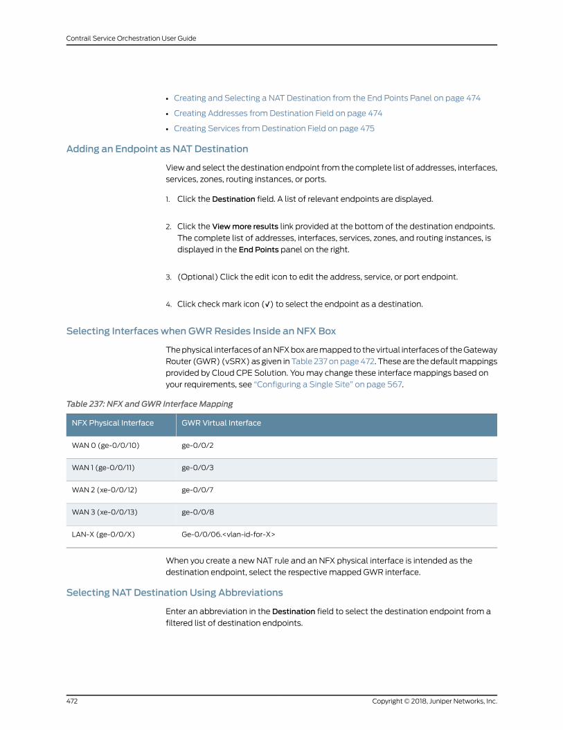
• Creating and Selecting a NAT Destination from the End Points Panel on page 474
• Creating Addresses from Destination Field on page 474
• Creating Services from Destination Field on page 475
Adding an Endpoint as NAT Destination
Viewand select the destination endpoint from the complete list of addresses, interfaces,
services, zones, routing instances, or ports.
1. Click the Destination field. A list of relevant endpoints are displayed.
2. Click the Viewmore results link provided at the bottom of the destination endpoints.
The complete list of addresses, interfaces, services, zones, and routing instances, is
displayed in the End Points panel on the right.
3. (Optional) Click the edit icon to edit the address, service, or port endpoint.
4. Click check mark icon (√) to select the endpoint as a destination.
Selecting Interfaces when GWRResides Inside an NFX Box
Thephysical interfacesofanNFXboxaremapped to thevirtual interfacesof theGateway
Router (GWR) (vSRX) as given in Table 237 onpage472. These are the defaultmappings
provided by Cloud CPE Solution. Youmay change these interface mappings based on
your requirements, see “Configuring a Single Site” on page 567.
Table 237: NFX and GWR Interface Mapping
GWRVirtual InterfaceNFX Physical Interface
ge-0/0/2WAN 0 (ge-0/0/10)
ge-0/0/3WAN 1 (ge-0/0/11)
ge-0/0/7WAN 2 (xe-0/0/12)
ge-0/0/8WAN 3 (xe-0/0/13)
Ge-0/0/06.<vlan-id-for-X>LAN-X (ge-0/0/X)
When you create a new NAT rule and an NFX physical interface is intended as the
destination endpoint, select the respective mapped GWR interface.
Selecting NAT Destination Using Abbreviations
Enter an abbreviation in the Destination field to select the destination endpoint from a
filtered list of destination endpoints.
Copyright © 2018, Juniper Networks, Inc.472
Contrail Service Orchestration User Guide
• To view a filtered list of addresses, enter ADDR or addr.
• To view a filtered list of interfaces, enter INTR or intr.
• To view a filtered list of services, enter SVCS or svcs.
• To view a filtered list of zones, enter ZONE or zone.
• To view a filtered list of routing instances, enter ROUT or rout.
Click the endpoints in the filtered list to select them.
You can add a port number as a destination endpoint. To do so:
1. Enter PORT or port in Destination.
2. Press Tab.
3. Enter the port number and press Enter.
You can also enter a range of ports by using the separator -. For example, you canenter 10-20.
The entered port value is selected as a destination endpoint.
Youcanalso select theendpoint fromthecomplete list of addresses, interfaces, services,
zones, and routing instances. See “Adding an Endpoint as NATDestination” on page 472.
Selecting a NAT Destination from the End Points Panel
You can select a NAT destination endpoint from the End Points panel. Alternately, you
can create a newNAT destination endpoint from the EndPoints panel, see “Creating and
Selecting a NAT Destination from the End Points Panel” on page 474.
To select a NAT destination endpoint from the End Points panel:
1. Click the Destination field.
2. Click the lesser-than icon (<) on the right.
The End Points panel appears, displaying the list of available addresses, interfaces,
services, zones, and routing instances.
3. (Optional) To viewmore information about a destination endpoint, click the details
icon on the right of the endpoint. To edit the destination endpoint, click the edit icon
(pencil symbol) on the right of the endpoint.
473Copyright © 2018, Juniper Networks, Inc.
Chapter 35: Managing NAT Policies
NOTE: You can only edit or view details of a destination endpoint if theseoptions appear on right side of the endpoint when you hover over it. Notall endpoints provide these options.
4. Click the check mark icon (√) to add the endpoint as a destination.
Creating and Selecting a NAT Destination from the End Points Panel
To create a new destination endpoint from the End Points panel:
1. Click the add icon (+) on the top right of the panel and select the type of endpoint
you want to create, among the options provided.
Basedon theoption you select, the respectivepageappears. Fill in the requireddetails
to create a new endpoint.
• To create a new address, see “Creating Addresses or Address Groups” on page 507.
• To create a new service, see “Creating Services and Service Groups” on page 512.
After the endpoint is created, it appears in the Endpoints panel.
2. Click the check mark icon (√) to add the new endpoint as a destination.
Creating Addresses fromDestination Field
You can use one of the following ways to create a new address from the Destination and
use the newly created address as a destination endpoint:
• Type the address directly in the Destination field. If the address is valid, it is created
immediately and added as a destination endpoint.
• Create an address from the Destination field, using the following steps:
1. In the Destination field, type addr. The Add new address link appears at the bottom
of the list of addresses.
2. Click Add new address to create a new address.
The Create Addresses page appears.
3. Configure thenewaddress.See “CreatingAddressesorAddressGroups”onpage507.
4. Click Save to save the new address.
Thenewaddress is created, andwill be listedasanoption for thedestination. Select
the new address to add it to the destination.
Copyright © 2018, Juniper Networks, Inc.474
Contrail Service Orchestration User Guide
Creating Services fromDestination Field
To create a new service from the Destination field and use the newly created service as
a destination endpoint:
1. In the Destination link, type svcs. The Add new service link appears at the bottom of
the list of services.
2. Click Add new service to create a new service.
The Create Services page appears.
3. Configure the new service. See “Creating Services and Service Groups” on page 512.
4. Click Save to save the new service.
The new service is created, and will be listed as an option for the destination. Select
the new service to add it to the destination.
RelatedDocumentation
About the Single NAT Policy Page on page 458•
• Editing, Cloning, and Deleting NAT Policy Rules on page 466
• Creating NAT Policy Rules on page 460
• Deploying NAT Policy Rules on page 467
• NAT Policies Overview on page 452
• About the NAT Policies Page on page 454
• Creating NAT Policies on page 455
• Editing and Deleting NAT Policies on page 457
NAT Pools Overview
A NAT pool is a set of IP addresses that you can define and use for address translation.
NAT policies perform address translation by translating internal IP addresses to the
addresses in these pools. Unlike static NAT, where there is a one-to-onemapping that
includes destination IP address translation in one direction and source IP address
translation in the reverse direction, with source NAT, you translate the original source IP
address to an IP address in the address pool. With destination NAT, you translate the
original destination address to an IP address in the address pool.
RelatedDocumentation
NAT Policies Overview on page 452•
• About the NAT Pools Page on page 476
• Creating NAT Pools on page 477
• Editing, Cloning, and Deleting NAT Pools on page 479
475Copyright © 2018, Juniper Networks, Inc.
Chapter 35: Managing NAT Policies
About the NAT Pools Page
To access this page, select Configuration > NAT > Pools.
Use the NAT Pools page to create, modify, clone, and delete NAT pools. You can filter
and sort this information to get a better understanding of what you want to configure.
Tasks You Can Perform
You can perform the following tasks from this page:
• Create a NAT pool. See “Creating NAT Pools” on page 477.
• Modify, clone, or delete a NAT pool. See “Editing, Cloning, and Deleting NAT Pools” on
page 479.
• View unused NAT pools by selectingMore > ShowUnused. Delete unused NAT pools
by selectingMore > Delete Unused Items.
• View duplicate NAT pools. SelectMore > ShowDuplicates. The ShowDuplicates page
appears, displaying duplicate NAT pools. To delete a duplicate NAT pool, select it and
click the delete icon (X).
• View the details of a NAT pool by selectingMore > Detailed View, or by right-clicking a
NAT pool and select Detailed View. See “Viewing Object Details” on page 241.
• Search for a specific NAT pool. See “Searching for Text in an Object Data Table” on
page 242.
• Show or hide columns. Click the ShowHide Columns icon at the top right corner of the
page.
Table 238 on page 476 provides description of the fields on the NAT Pools page.
Table 238: Fields on the NAT Pools Page
DescriptionField
Displays the name of the NAT pool.Name
Displays the IP address of the NAT pool.Pool Address
Displays the description provided about the NAT pool when it was created.Description
Displays the NAT pool type. A NAT pool can be of type Source or Destination.Pool Type
RelatedDocumentation
NAT Pools Overview on page 475•
• Creating NAT Pools on page 477
• Editing, Cloning, and Deleting NAT Pools on page 479
Copyright © 2018, Juniper Networks, Inc.476
Contrail Service Orchestration User Guide
Creating NAT Pools
Use the Create NAT Pools page to create NAT pools.
To create a NAT pool:
1. Select Configuration > NAT > Pools.
The NAT Pools page appears.
2. Click the add icon (+).
The Create NAT Pool page displays fields required for creating and configuring a NAT
pool.
3. Complete the configuration according to the guidelines provided in
Table 239 on page 477.
4. ClickOK to save the changes. A NAT pool with the configuration you provided is
created.
If you want to discard your changes, click Cancel instead.
Table 239 on page 477 provides guidelines on using the fields on the Create NAT Pool
page.
Table 239: Fields on the Create NAT Pool Page
DescriptionField
General Information
Enter auniquestringofalphanumeric characters, dashes, andunderscores.Colons, andperiodsare not allowed, and themaximum length is 31 characters.
Name
Enter a description for the new NAT pool; maximum length is 1024 characters.Description
Select a NAT pool type to configure:
• Source
• Destination
Pool Type
Select a NAT pool address or click Add new address to create a new NAT pool address.Pool Address
Routing Instance
Select the site to which the NAT pool is applicable.
NOTE: In a hub and spoke topology, both hub and spoke sites are listed in theSite drop-down.Ensure that you select only a spoke site, when you are creating a destination NAT pool.
Site
Select the required routing instance from the list of available routing instances for the selectedsite.
Routing Instance
477Copyright © 2018, Juniper Networks, Inc.
Chapter 35: Managing NAT Policies
Table 239: Fields on the Create NAT Pool Page (continued)
DescriptionField
Advanced
Enter the base address of the original source IP address range. The Host Address Base is usedfor IP address shifting.
Host Address Base
Select the translation type for the incoming traffic:
• No Translation—There is no translation required for the incoming traffic.
• Port/Range—Set the global default single port range for source NAT pools with porttranslation.
• Overload—Multiple source addresses are translated to pool addresses. If you setOverloadas the translation type, the value of the Pool Address field cannot be an IP range or subnet,but it will be a single address.
Translation
Select a NAT address pooling behavior:
• Paired—Use this option for applications that require all sessionsassociatedwithone internalIP address to be translated to the same external IP address for multiple sessions.
• Non-Paired—Use this option for applications that can be assigned IP addresses in around-robin fashion.
Address Pooling
Enter the port number for the destination NAT pool type.Port
Enter the start port range for the source NAT pools, if the translation type is Port/Range. Thevalue of the port range can be any value between 1024 to 65535.
Start
Enter the end port range. The value of the port range can be any value between 1024 to 65535.End
Configure the port overloading capacity for a source NAT pool. If the factor is set to x, eachtranslated IP address has x times the maximum number of ports available. The value of theport overloading factor can range between 2 and 32.
Port Overloading Factor
Enable address sharing so that multiple internal IP addresses can bemapped to the sameexternal IP address. Select this option only when the source NAT pool is configured with noport translation.Whena sourceNATpool has only oneor a fewexternal IP addresses available,the address sharing option with amany-to-one address mapping increases NAT resourcesand improves traffic.
Address Sharing
Select a source pool to use when the current address pool is exhausted.
• Interface—Allow the egress interface IP address to support overflow.
• Pool—Name of the source address pool.
• Overflow Pool—When addresses from the original source NAT pool are exhausted, IPaddresses and port numbers are allocated from the overflow pool. A user-defined sourceNAT pool or an egress interface can be used as the overflow pool. (When the overflowpool is used, the pool ID is returned with the address.)
Overflow Pool Type
RelatedDocumentation
NAT Pools Overview on page 475•
• About the NAT Pools Page on page 476
Copyright © 2018, Juniper Networks, Inc.478
Contrail Service Orchestration User Guide
• Editing, Cloning, and Deleting NAT Pools on page 479
Editing, Cloning, and Deleting NAT Pools
• Editing NAT Pools on page 479
• Cloning NAT Pools on page 479
• Deleting NAT Pools on page 480
Editing NAT Pools
Tomodify the parameters configured for a NAT pool:
1. Select Configuration > NAT > Pools.
The NAT Pools page appears.
2. Select the NAT pool that you want to edit, and click the edit icon (pencil symbol) at
the top right corner of the table, or right-click and select Edit NAT Pool.
TheEditNATPoolpage appears, displaying the sameoptions that are displayedwhen
creating a new NAT pool.
3. Modify the parameters according to the guidelines provided in “Creating NAT Pools”
on page 477.
4. ClickOK to save the changes. If you clickOK, you see themodified NAT pool in the
NAT Pools page.
If you want to discard your changes, click Cancel instead.
Cloning NAT Pools
To clone a NAT pool:
1. Select Configuration > NAT > Pools.
The NAT Pools page appears.
2. Right-click the NAT pool that you want to clone and then click Clone, or selectMore
> Clone.
The Clone NAT Pool page appears with editable fields. Modify the parameters of the
cloned NAT pool as per your requirements.
3. ClickOK to save the changes. If you clickOK, the cloned NAT pool appears at the end
of the NAT pools list in the NAT Pools page.
If you want to discard your changes, click Cancel instead.
479Copyright © 2018, Juniper Networks, Inc.
Chapter 35: Managing NAT Policies
Deleting NAT Pools
To delete a NAT pool:
1. Select Configuration > NAT > Pools.
The NAT Pools page appears.
2. Select the NAT pool you want to delete and then click the delete icon (X) .
An alert message appears, verifying that you want to delete the NAT pool.
3. Click Yes to delete the NAT pool. If you click Yes, the selected NAT pool is deleted.
If you do not want to delete, click Cancel instead.
RelatedDocumentation
• NAT Pools Overview on page 475
• About the NAT Pools Page on page 476
• Creating NAT Pools on page 477
Copyright © 2018, Juniper Networks, Inc.480
Contrail Service Orchestration User Guide
CHAPTER 36
Managing SSL Proxies
• SSL Forward Proxy Overview on page 481
• About the SSL Proxy Policy Page on page 486
• Creating SSL Proxy Policy Intents on page 487
• Editing, Cloning, and Deleting SSL Proxy Policy Intents on page 490
• Understanding How SSL Proxy Policy Intents Are Applied on page 492
• About the SSL Proxy Profiles Page on page 494
• Creating SSL Forward Proxy Profiles on page 496
• Editing, Cloning, and Deleting SSL Forward Proxy Profiles on page 500
• Configuring and Deploying an SSL Forward Proxy Policy on page 502
SSL Forward Proxy Overview
Secure Sockets Layer (SSL) is an application-level protocol that provides encryption
technology for the Internet. SSL, also called Transport Layer Security (TLS), ensures the
secure transmission of data between a client and a server through a combination of
privacy, authentication, confidentiality, and data integrity. SSL relies on certificates and
private–public key exchange pairs for this level of security.
Serverauthenticationguardsagainst fraudulent transmissionsbyenablingaWebbrowser
to validate the identity of aWeb server. Confidentiality mechanisms ensure that
communications are private. SSL enforces confidentiality by encrypting data to prevent
unauthorized users fromeavesdropping on electronic communications. Finally,message
integrity ensures that the contents of a communication have not been tampered with.
SSL forward proxy is a transparent proxy; that is, it performs SSL encryption and
decryption between the client and the server, but neither the server nor the client can
detect its presence. SSL forwardproxy ensures that it has the keys to encrypt anddecrypt
the payload:
• For theserver, SSL forwardproxyactsasaclient—BecauseSSL forwardproxygenerates
the shared pre-master key, it determines the keys to encrypt and decrypt.
• For theclient, SSL forwardproxyactsasa server—SSL forwardproxy first authenticates
the original server and replaces the public key in the original server certificate with a
key that is known to it. It thengeneratesanewcertificateby replacing theoriginal issuer
of the certificate with its own identity and signs this new certificate with its own public
481Copyright © 2018, Juniper Networks, Inc.
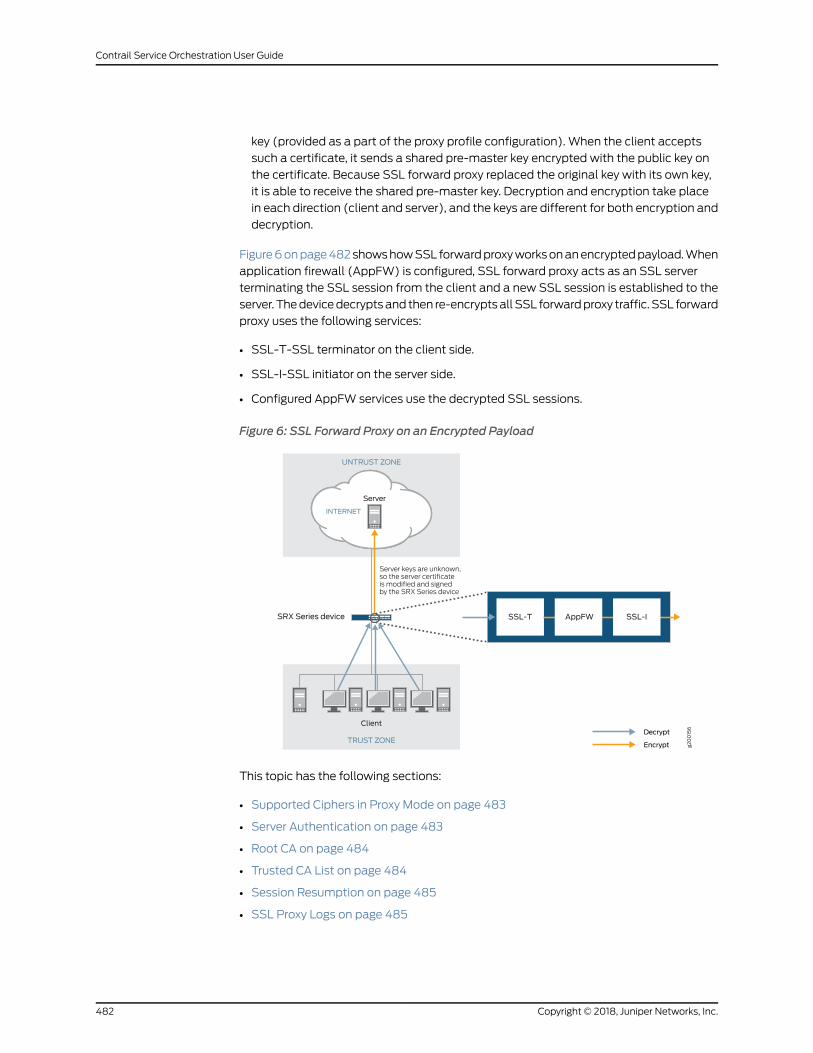
key (provided as a part of the proxy profile configuration). When the client accepts
such a certificate, it sends a shared pre-master key encrypted with the public key on
the certificate. Because SSL forward proxy replaced the original key with its own key,
it is able to receive the shared pre-master key. Decryption and encryption take place
in each direction (client and server), and the keys are different for both encryption and
decryption.
Figure6onpage482showshowSSL forwardproxyworksonanencryptedpayload.When
application firewall (AppFW) is configured, SSL forward proxy acts as an SSL server
terminating the SSL session from the client and a new SSL session is established to the
server. Thedevicedecryptsand then re-encryptsall SSL forwardproxy traffic. SSL forward
proxy uses the following services:
• SSL-T-SSL terminator on the client side.
• SSL-I-SSL initiator on the server side.
• Configured AppFW services use the decrypted SSL sessions.
Figure 6: SSL Forward Proxy on an Encrypted Payload
g200156
Server keys are unknown,so the server certificateis modified and signedby the SRX Series device
UNTRUST ZONE
INTERNET
TRUST ZONE
Server
Client
SRX Series device SSL-T SSL-IAppFW
Decrypt
Encrypt
This topic has the following sections:
• Supported Ciphers in Proxy Mode on page 483
• Server Authentication on page 483
• Root CA on page 484
• Trusted CA List on page 484
• Session Resumption on page 485
• SSL Proxy Logs on page 485
Copyright © 2018, Juniper Networks, Inc.482
Contrail Service Orchestration User Guide
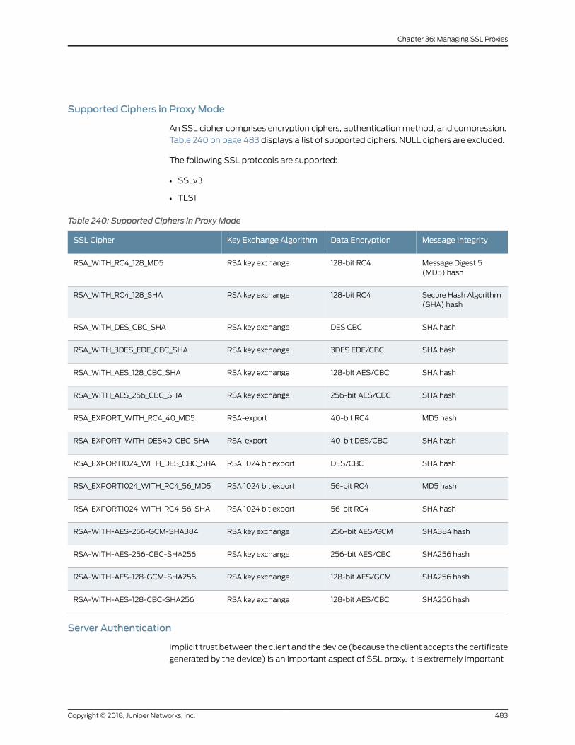
Supported Ciphers in ProxyMode
An SSL cipher comprises encryption ciphers, authentication method, and compression.
Table 240 on page 483 displays a list of supported ciphers. NULL ciphers are excluded.
The following SSL protocols are supported:
• SSLv3
• TLS1
Table 240: Supported Ciphers in Proxy Mode
Message IntegrityData EncryptionKey Exchange AlgorithmSSL Cipher
Message Digest 5(MD5) hash
128-bit RC4RSA key exchangeRSA_WITH_RC4_128_MD5
Secure Hash Algorithm(SHA) hash
128-bit RC4RSA key exchangeRSA_WITH_RC4_128_SHA
SHA hashDES CBCRSA key exchangeRSA_WITH_DES_CBC_SHA
SHA hash3DES EDE/CBCRSA key exchangeRSA_WITH_3DES_EDE_CBC_SHA
SHA hash128-bit AES/CBCRSA key exchangeRSA_WITH_AES_128_CBC_SHA
SHA hash256-bit AES/CBCRSA key exchangeRSA_WITH_AES_256_CBC_SHA
MD5 hash40-bit RC4RSA-exportRSA_EXPORT_WITH_RC4_40_MD5
SHA hash40-bit DES/CBCRSA-exportRSA_EXPORT_WITH_DES40_CBC_SHA
SHA hashDES/CBCRSA 1024 bit exportRSA_EXPORT1024_WITH_DES_CBC_SHA
MD5 hash56-bit RC4RSA 1024 bit exportRSA_EXPORT1024_WITH_RC4_56_MD5
SHA hash56-bit RC4RSA 1024 bit exportRSA_EXPORT1024_WITH_RC4_56_SHA
SHA384 hash256-bit AES/GCMRSA key exchangeRSA-WITH-AES-256-GCM-SHA384
SHA256 hash256-bit AES/CBCRSA key exchangeRSA-WITH-AES-256-CBC-SHA256
SHA256 hash128-bit AES/GCMRSA key exchangeRSA-WITH-AES-128-GCM-SHA256
SHA256 hash128-bit AES/CBCRSA key exchangeRSA-WITH-AES-128-CBC-SHA256
Server Authentication
Implicit trust between theclient and thedevice (because theclient accepts thecertificate
generated by the device) is an important aspect of SSL proxy. It is extremely important
483Copyright © 2018, Juniper Networks, Inc.
Chapter 36: Managing SSL Proxies
that serverauthentication isnot compromised; however, in reality, self-signedcertificates
and certificates with anomalies are in abundance. Anomalies can include expired
certificates, instances of common name not matching a domain name, and so forth.
You can specify that the SSL forward proxy should ignore server authentication
completely. In this case, SSL forward proxy ignores errors encountered during the server
certificate verification process (such as CA signature verification failure, self-signed
certificates, and certificate expiry).
You can specify whether the SSL proxy should ignore server authentication errors or not
during the creation of an SSL forward proxy profile.
• If you specify that server authentication errors should not be ignored, the following
scenarios occur:
• If authentication succeeds, a new certificate is generated by replacing the keys and
changing the issuer name to the issuer name that is configured in the root CA
certificate in the proxy profile.
• If authentication fails, the connection is dropped.
• If youspecify that serverauthenticationerrors shouldbe ignored, the followingscenarios
occur:
NOTE: We do not recommend that you configure this option forauthentication because configuring it results in websites not beingauthenticatedatall.However, youcanuse thisoption toeffectively identifythe root cause for dropped SSL sessions.
• If the certificate is self-signed, a new certificate is generated by replacing the keys
only. The issuer name is not changed. This ensures that the client browser displays
a warning that the certificate is not valid.
• If the certificate has expired or if the common name does not match the domain
name, a new certificate is generated by replacing the keys and changing the issuer
name to SSL-PROXY: DUMMY_CERT:GENERATED DUE TO SRVR AUTH FAILURE.
This ensures that the client browser displays a warning that the certificate is not
valid.
Root CA
In a public key infrastructure (PKI) hierarchy, the root CA is at the top of the trust path.
The root CA identifies the server certificate as a trusted certificate.
Trusted CA List
SSL forward proxy ensures secure transmission of data between a client and a server.
Before establishing a secure connection, SSL forward proxy checks certificate authority
(CA) certificates to verify signatures on server certificates. For this reason, a reasonable
list of trusted CA certificates is required to effectively authenticate servers.
Copyright © 2018, Juniper Networks, Inc.484
Contrail Service Orchestration User Guide
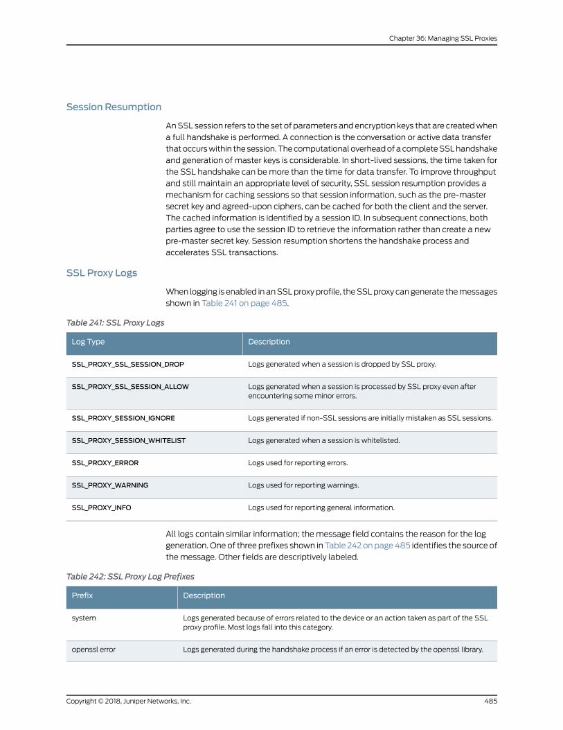
Session Resumption
AnSSL session refers to the set of parameters andencryption keys that are createdwhen
a full handshake is performed. A connection is the conversation or active data transfer
thatoccurswithin thesession.ThecomputationaloverheadofacompleteSSLhandshake
and generation of master keys is considerable. In short-lived sessions, the time taken for
the SSL handshake can bemore than the time for data transfer. To improve throughput
and still maintain an appropriate level of security, SSL session resumption provides a
mechanism for caching sessions so that session information, such as the pre-master
secret key and agreed-upon ciphers, can be cached for both the client and the server.
The cached information is identified by a session ID. In subsequent connections, both
parties agree to use the session ID to retrieve the information rather than create a new
pre-master secret key. Session resumption shortens the handshake process and
accelerates SSL transactions.
SSL Proxy Logs
When logging is enabled inanSSLproxyprofile, theSSLproxy cangenerate themessages
shown in Table 241 on page 485.
Table 241: SSL Proxy Logs
DescriptionLog Type
Logs generated when a session is dropped by SSL proxy.SSL_PROXY_SSL_SESSION_DROP
Logs generated when a session is processed by SSL proxy even afterencountering someminor errors.
SSL_PROXY_SSL_SESSION_ALLOW
Logs generated if non-SSL sessions are initiallymistaken as SSL sessions.SSL_PROXY_SESSION_IGNORE
Logs generated when a session is whitelisted.SSL_PROXY_SESSION_WHITELIST
Logs used for reporting errors.SSL_PROXY_ERROR
Logs used for reporting warnings.SSL_PROXY_WARNING
Logs used for reporting general information.SSL_PROXY_INFO
All logs contain similar information; the message field contains the reason for the log
generation. One of three prefixes shown in Table 242 onpage485 identifies the source of
the message. Other fields are descriptively labeled.
Table 242: SSL Proxy Log Prefixes
DescriptionPrefix
Logs generated because of errors related to the device or an action taken as part of the SSLproxy profile. Most logs fall into this category.
system
Logs generated during the handshake process if an error is detected by the openssl library.openssl error
485Copyright © 2018, Juniper Networks, Inc.
Chapter 36: Managing SSL Proxies
Table 242: SSL Proxy Log Prefixes (continued)
DescriptionPrefix
Logs generated during the handshake process if an error is detected in the certificate (X.509related errors).
certificate error
RelatedDocumentation
About the SSL Proxy Policy Page on page 486•
• About the SSL Proxy Profiles Page on page 494
• Certificates Overview on page 617
About the SSL Proxy Policy Page
To access this page, select Configuration > SSL Proxy > Policy in Customer Portal.
Use the SSL Proxy Policy page to view andmanage SSL proxy policy intents. You can
also deploy the SSL proxy policy immediately or schedule the deployment for later.
NOTE:
• When an SSL proxy intent is deployed, the corresponding certificates usedin the SSL profile (associatedwith the SSL proxy intent) are automaticallydeployed to the applicable sites.
• If the application firewall (AppFW) service is not configured in thecorresponding firewall policy intent, then the SSL forward proxy servicesare bypassed even if an SSL proxy profile is attached to a firewall policy.Therefore, ensure that AppFW is configured for the firewall policy intentsthat shouldgo throughSSL inspection. IfAppFw isnot included in thepolicyintent, this does not cause an error; however, the SSL proxy action doesnot take place even though sessions arematched.
Tasks You Can Perform
You can perform the following tasks from this page:
• Create SSL proxy policy intents—See “Creating SSL Proxy Policy Intents” on page 487.
• Edit, clone, or delete SSL proxy policy intents—See “Editing, Cloning, and Deleting SSL
Proxy Policy Intents” on page 490.
• Search for SSL proxy policy intents by using keywords—Click the search icon and enter
the search term in the text box and press Enter. The search results are displayed on
the same page.
• Filter SSL proxy policy intents—Click the filter icon and select whether you want to
show or hide column filters or apply a quick filter. Depending on your selection, you
Copyright © 2018, Juniper Networks, Inc.486
Contrail Service Orchestration User Guide
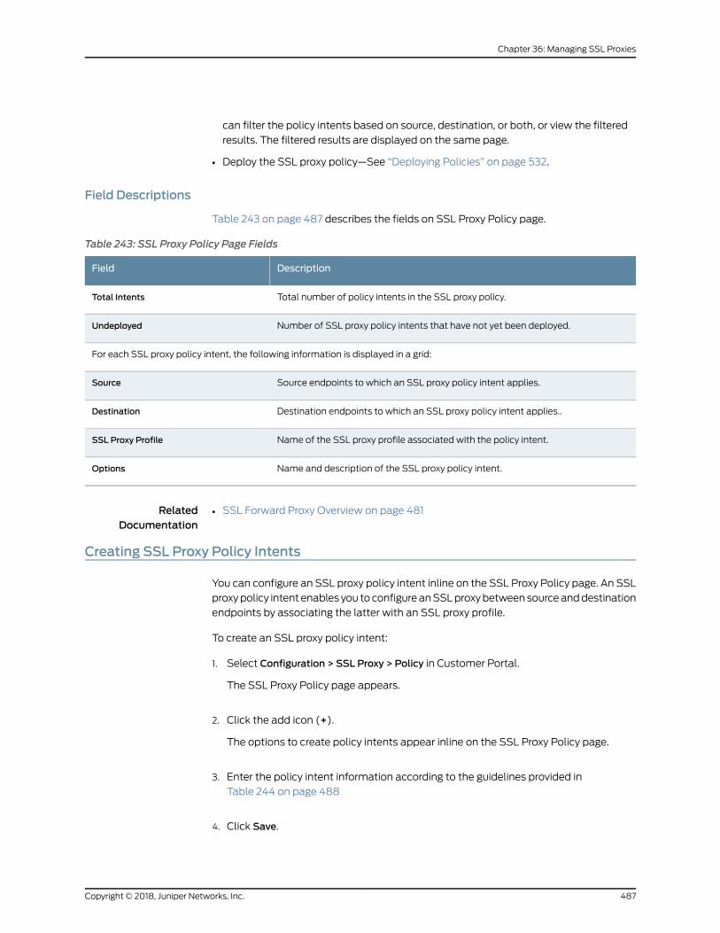
can filter the policy intents based on source, destination, or both, or view the filtered
results. The filtered results are displayed on the same page.
• Deploy the SSL proxy policy—See “Deploying Policies” on page 532.
Field Descriptions
Table 243 on page 487 describes the fields on SSL Proxy Policy page.
Table 243: SSL Proxy Policy Page Fields
DescriptionField
Total number of policy intents in the SSL proxy policy.Total Intents
Number of SSL proxy policy intents that have not yet been deployed.Undeployed
For each SSL proxy policy intent, the following information is displayed in a grid:
Source endpoints to which an SSL proxy policy intent applies.Source
Destination endpoints to which an SSL proxy policy intent applies..Destination
Name of the SSL proxy profile associated with the policy intent.SSL Proxy Profile
Name and description of the SSL proxy policy intent.Options
RelatedDocumentation
SSL Forward Proxy Overview on page 481•
Creating SSL Proxy Policy Intents
You can configure an SSL proxy policy intent inline on the SSL Proxy Policy page. An SSL
proxypolicy intent enables you toconfigureanSSLproxybetweensourceanddestination
endpoints by associating the latter with an SSL proxy profile.
To create an SSL proxy policy intent:
1. Select Configuration > SSL Proxy > Policy in Customer Portal.
The SSL Proxy Policy page appears.
2. Click the add icon (+).
The options to create policy intents appear inline on the SSL Proxy Policy page.
3. Enter the policy intent information according to the guidelines provided in
Table 244 on page 488
4. Click Save.
487Copyright © 2018, Juniper Networks, Inc.
Chapter 36: Managing SSL Proxies
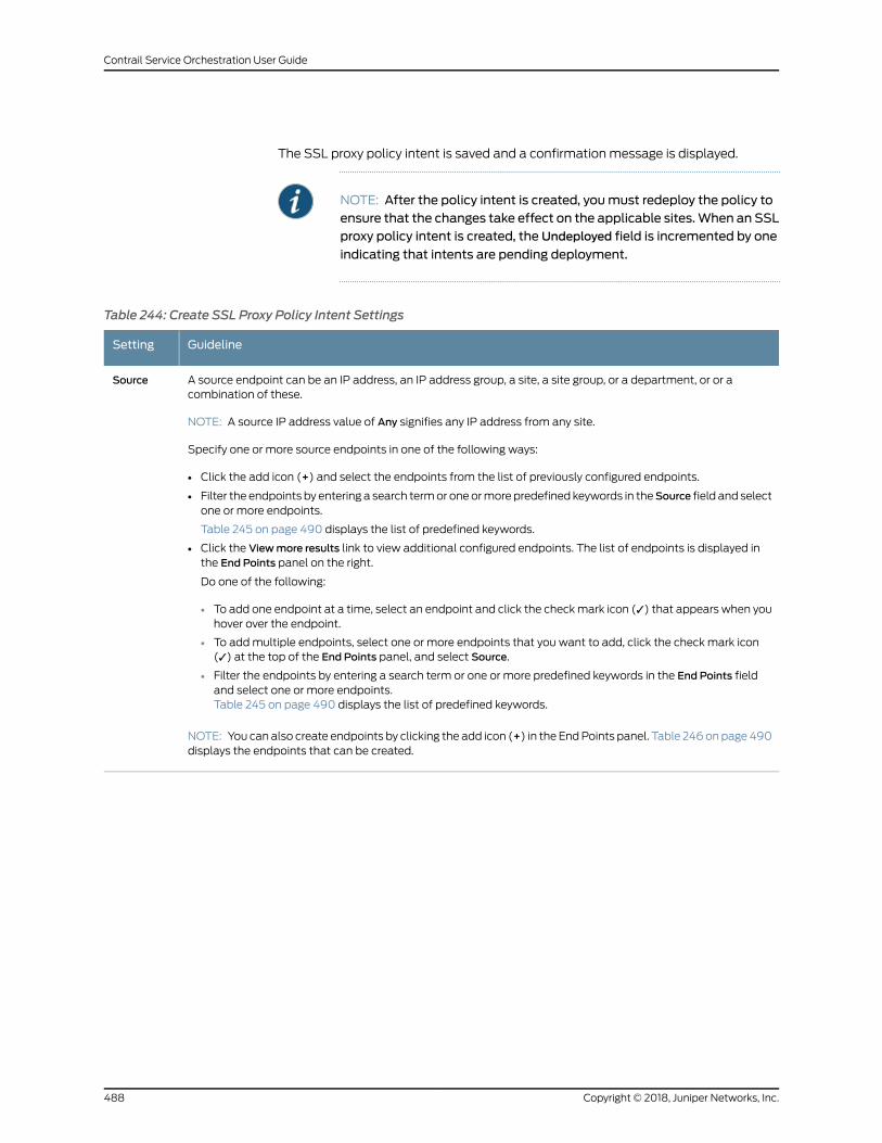
The SSL proxy policy intent is saved and a confirmation message is displayed.
NOTE: After the policy intent is created, youmust redeploy the policy toensure that the changes take effect on the applicable sites.When an SSLproxy policy intent is created, the Undeployed field is incremented by one
indicating that intents are pending deployment.
Table 244: Create SSL Proxy Policy Intent Settings
GuidelineSetting
A source endpoint can be an IP address, an IP address group, a site, a site group, or a department, or or acombination of these.
NOTE: A source IP address value of Any signifies any IP address from any site.
Specify one or more source endpoints in one of the following ways:
• Click the add icon (+) and select the endpoints from the list of previously configured endpoints.
• Filter the endpoints by entering a search termor oneormore predefined keywords in theSource field and selectone or more endpoints.
Table 245 on page 490 displays the list of predefined keywords.
• Click the Viewmore results link to view additional configured endpoints. The list of endpoints is displayed inthe End Points panel on the right.
Do one of the following:
• To add one endpoint at a time, select an endpoint and click the checkmark icon (✓) that appears when youhover over the endpoint.
• To addmultiple endpoints, select one or more endpoints that you want to add, click the check mark icon(✓) at the top of the End Points panel, and select Source.
• Filter the endpoints by entering a search term or one or more predefined keywords in the End Points fieldand select one or more endpoints.Table 245 on page 490 displays the list of predefined keywords.
NOTE: You can also create endpoints by clicking the add icon (+) in the EndPoints panel. Table 246onpage 490displays the endpoints that can be created.
Source
Copyright © 2018, Juniper Networks, Inc.488
Contrail Service Orchestration User Guide
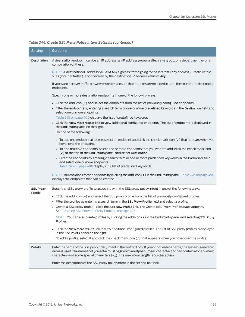
Table 244: Create SSL Proxy Policy Intent Settings (continued)
GuidelineSetting
A destination endpoint can be an IP address, an IP address group, a site, a site group, or a department, or or acombination of these.
NOTE: A destination IP address value of Any signifies traffic going to the Internet (any address). Traffic withinsites (internal traffic) is not covered by the destination IP address value of Any.
If youwant to cover traffic between twosites, ensure that the sites are included in both the sourceanddestinationendpoints.
Specify one or more destination endpoints in one of the following ways:
• Click the add icon (+) and select the endpoints from the list of previously configured endpoints.
• Filter the endpoints by entering a search term or one or more predefined keywords in the Destination field andselect one or more endpoints.
Table 245 on page 490 displays the list of predefined keywords.
• Click the Viewmore results link to view additional configured endpoints. The list of endpoints is displayed inthe End Points panel on the right.
Do one of the following:
• To add one endpoint at a time, select an endpoint and click the checkmark icon (✓) that appears when youhover over the endpoint.
• To addmultiple endpoints, select one or more endpoints that you want to add, click the check mark icon(✓) at the top of the End Points panel, and select Destination.
• Filter the endpoints by entering a search term or one or more predefined keywords in the End Points fieldand select one or more endpoints.Table 245 on page 490 displays the list of predefined keywords.
NOTE: You can also create endpoints by clicking the add icon (+) in the EndPoints panel. Table 246onpage 490displays the endpoints that can be created.
Destination
Specify an SSL proxy profile to associate with the SSL proxy policy intent in one of the following ways:
• Click the add icon (+) and select the SSL proxy profile from the list of previously configured profiles.
• Filter the profiles by entering a search term in the SSL Proxy Profile field and select a profile.
• Create a SSL proxy profile—Click the Add NewProfile link. The Create SSL Proxy Profiles page appears.See“Creating SSL Forward Proxy Profiles” on page 496.
NOTE: You can also create profiles by clicking the add icon (+) in the EndPoints panel and selectingSSLProxyProfiles.
• Click the Viewmore results link to view additional configured profiles. The list of SSL proxy profiles is displayedin the End Points panel on the right.
To add a profile, select it and click the check mark icon (✓) that appears when you hover over the profile.
SSL ProxyProfile
Enter thenameof theSSLproxypolicy intent in the first textbox. If youdonotenter aname, thesystem-generatedname isused.Thenamethat youentermustbeginwithanalphanumericcharacterandcancontainalphanumericcharacters and some special characters (- _). Themaximum length is 63 characters.
Enter the description of the SSL proxy policy intent in the second text box.
Details
489Copyright © 2018, Juniper Networks, Inc.
Chapter 36: Managing SSL Proxies
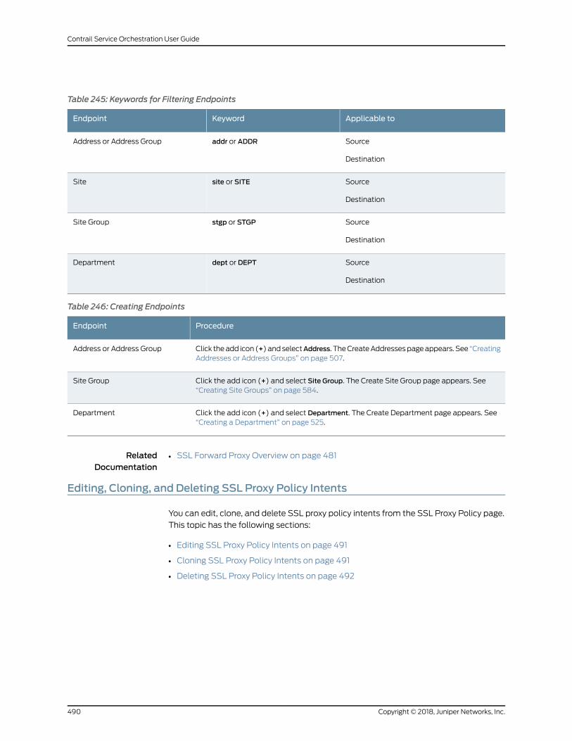
Table 245: Keywords for Filtering Endpoints
Applicable toKeywordEndpoint
Source
Destination
addr or ADDRAddress or Address Group
Source
Destination
site or SITESite
Source
Destination
stgp or STGPSite Group
Source
Destination
dept or DEPTDepartment
Table 246: Creating Endpoints
ProcedureEndpoint
Click theadd icon (+)andselectAddress. TheCreateAddressespageappears. See “CreatingAddresses or Address Groups” on page 507.
Address or Address Group
Click the add icon (+) and select Site Group. The Create Site Group page appears. See“Creating Site Groups” on page 584.
Site Group
Click the add icon (+) and select Department. The Create Department page appears. See“Creating a Department” on page 525.
Department
RelatedDocumentation
SSL Forward Proxy Overview on page 481•
Editing, Cloning, and Deleting SSL Proxy Policy Intents
You can edit, clone, and delete SSL proxy policy intents from the SSL Proxy Policy page.
This topic has the following sections:
• Editing SSL Proxy Policy Intents on page 491
• Cloning SSL Proxy Policy Intents on page 491
• Deleting SSL Proxy Policy Intents on page 492
Copyright © 2018, Juniper Networks, Inc.490
Contrail Service Orchestration User Guide
Editing SSL Proxy Policy Intents
Tomodify the parameters configured for an SSL proxy policy intent:
1. Select Configuration > SSL Proxy > Policy in Customer Portal.
The SSL Proxy Policy page appears, displaying the intents associated with the policy.
2. Hover over the SSL proxy policy intent that you want to edit, and then click the edit
icon (pencil symbol) that appears on the right side of the intent.
You can nowmodify the policy intent inline on the SSL Proxy Policy page.
3. Modify the parameters following the guidelines provided in “CreatingSSLProxyPolicy
Intents” on page 487.
4. Click Save to save your changes.
The SSL proxy policy intent is saved and a confirmation message is displayed.
NOTE: After a policy intent is modified, youmust redeploy the policy toensure that the changes take effect on the relevant sites. When an SSLproxy policy intent ismodified, theUndeployed field is incrementedbyone
indicating that intents are pending deployment.
Cloning SSL Proxy Policy Intents
Cloning enables you to easily create a new SSL proxy policy intent based on an existing
one.
To clone an SSL proxy policy intent:
1. Select Configuration > SSL Proxy > Policy in Customer Portal.
The SSL Proxy Policy page appears, displaying the intents associated with the policy.
2. Hover over the SSL proxy policy intent that youwant to clone, and then click the clone
icon that appears on the right side of the intent.
You canmodify the cloned policy intent inline on the SSL Proxy Policy page.
3. Modify the parameters following the guidelines provided in “CreatingSSLProxyPolicy
Intents” on page 487.
4. Click Save to save your changes.
The SSL proxy policy intent is cloned and a confirmation message is displayed.
491Copyright © 2018, Juniper Networks, Inc.
Chapter 36: Managing SSL Proxies
NOTE: After a policy intent is cloned, youmust redeploy the policy toensure that the changes take effect on the relevant sites. When an SSLproxy policy intent is cloned, the Undeployed field is incremented by one
indicating that one or more intents are pending deployment.
Deleting SSL Proxy Policy Intents
To delete one or more SSL proxy policy intents:
1. Select Configuration > SSL Proxy > Policy in Customer Portal.
The SSL Proxy Policy page appears, displaying the intents associated with the policy.
2. Select the SSL proxy policy intents that you want to delete and then click the delete
icon (X).
You are asked to confirm the delete operation.
3. Click Yes to delete the selected SSL proxy policy intents.
A confirmation message appears indicating the status of the delete operation.
NOTE: After one or more policy intents are deleted, youmust redeploythe policy to ensure that the changes take effect on the applicable sites.
RelatedDocumentation
About the SSL Proxy Policy Page on page 486•
Understanding HowSSL Proxy Policy Intents Are Applied
When you deploy an SSL proxy policy, SSL proxy profiles are deployed to the applicable
sites based on SSL proxy policy intents. The deployments of firewall and SSL polices are
related in that firewall policy deployments take into account the last-deployed SSL
snapshots and vice versa. Therefore, even if an SSL proxy profile is deployed to the
applicable sites, it is applied only to traffic to which the firewall policy intent applies.
The decision regardingwhich SSL proxy profile is attached to a firewall policy intent is
based onmatching criteria between SSL proxy policy and firewall policy intents. In
addition, if there is a match between the SSL proxy policy intent and the firewall policy
intent, the SSL profile is applied only to the policy intents that are common between the
firewall and the SSL proxy policies.
Copyright © 2018, Juniper Networks, Inc.492
Contrail Service Orchestration User Guide
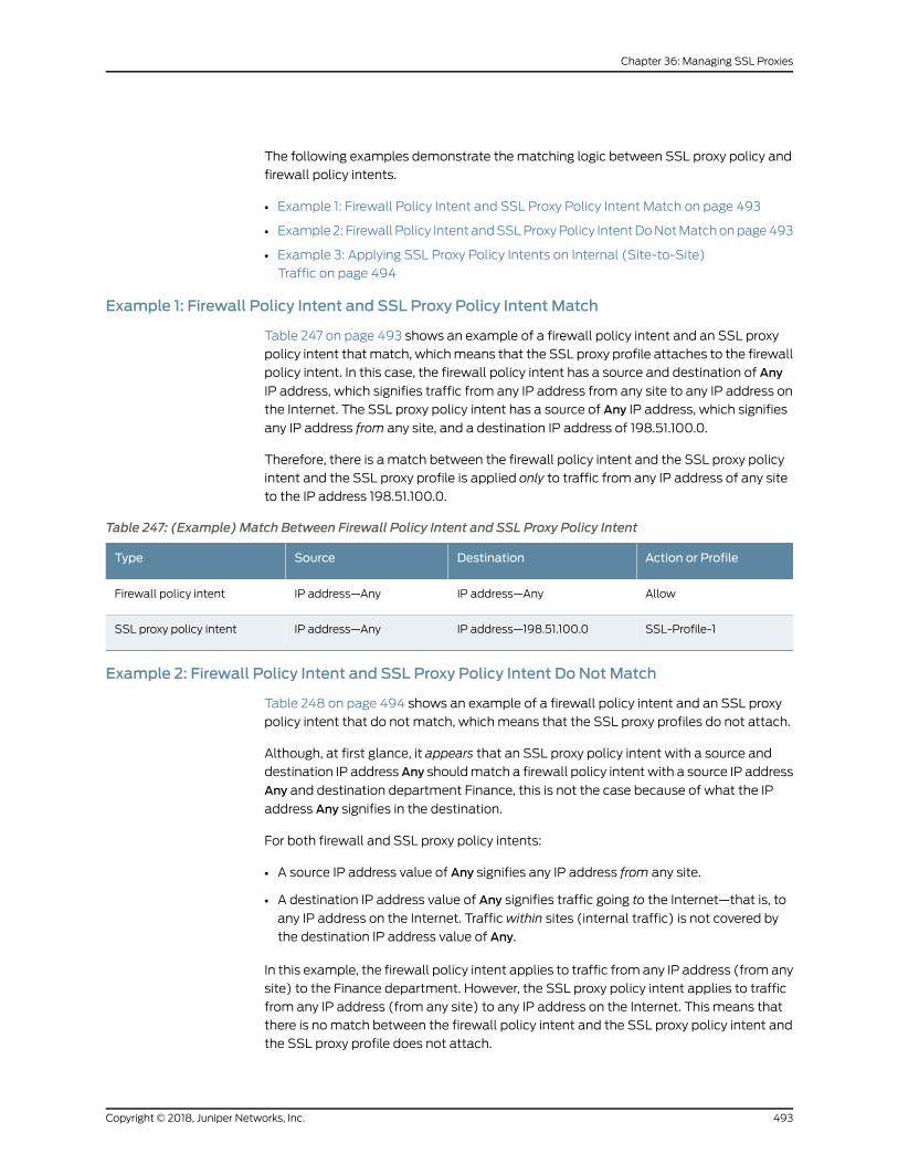
The following examples demonstrate the matching logic between SSL proxy policy and
firewall policy intents.
• Example 1: Firewall Policy Intent and SSL Proxy Policy Intent Match on page 493
• Example2: Firewall Policy IntentandSSLProxyPolicy IntentDoNotMatchonpage493
• Example 3: Applying SSL Proxy Policy Intents on Internal (Site-to-Site)
Traffic on page 494
Example 1: Firewall Policy Intent and SSL Proxy Policy Intent Match
Table 247 on page 493 shows an example of a firewall policy intent and an SSL proxy
policy intent thatmatch, whichmeans that the SSL proxy profile attaches to the firewall
policy intent. In this case, the firewall policy intent has a source and destination of Any
IP address, which signifies traffic from any IP address from any site to any IP address on
the Internet. The SSL proxy policy intent has a source of Any IP address, which signifies
any IP address from any site, and a destination IP address of 198.51.100.0.
Therefore, there is a match between the firewall policy intent and the SSL proxy policy
intent and the SSL proxy profile is applied only to traffic from any IP address of any site
to the IP address 198.51.100.0.
Table 247: (Example) Match Between Firewall Policy Intent and SSL Proxy Policy Intent
Action or ProfileDestinationSourceType
AllowIP address—AnyIP address—AnyFirewall policy intent
SSL-Profile-1IP address—198.51.100.0IP address—AnySSL proxy policy intent
Example 2: Firewall Policy Intent and SSL Proxy Policy Intent Do NotMatch
Table 248 on page 494 shows an example of a firewall policy intent and an SSL proxy
policy intent that do not match, which means that the SSL proxy profiles do not attach.
Although, at first glance, it appears that an SSL proxy policy intent with a source and
destination IP addressAny shouldmatch a firewall policy intent with a source IP address
Any and destination department Finance, this is not the case because of what the IP
address Any signifies in the destination.
For both firewall and SSL proxy policy intents:
• A source IP address value of Any signifies any IP address from any site.
• A destination IP address value of Any signifies traffic going to the Internet—that is, to
any IP address on the Internet. Trafficwithin sites (internal traffic) is not covered by
the destination IP address value of Any.
In this example, the firewall policy intent applies to traffic from any IP address (from any
site) to the Finance department. However, the SSL proxy policy intent applies to traffic
from any IP address (from any site) to any IP address on the Internet. This means that
there is nomatch between the firewall policy intent and the SSL proxy policy intent and
the SSL proxy profile does not attach.
493Copyright © 2018, Juniper Networks, Inc.
Chapter 36: Managing SSL Proxies
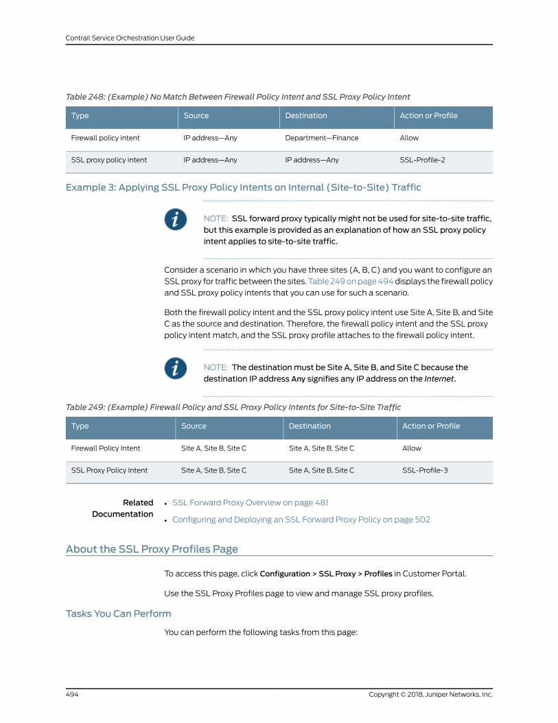
Table 248: (Example) NoMatch Between Firewall Policy Intent and SSL Proxy Policy Intent
Action or ProfileDestinationSourceType
AllowDepartment—FinanceIP address—AnyFirewall policy intent
SSL-Profile-2IP address—AnyIP address—AnySSL proxy policy intent
Example 3: Applying SSL Proxy Policy Intents on Internal (Site-to-Site) Traffic
NOTE: SSL forward proxy typically might not be used for site-to-site traffic,but this example is provided as an explanation of how an SSL proxy policyintent applies to site-to-site traffic.
Consider a scenario in which you have three sites (A, B, C) and you want to configure an
SSLproxy for traffic between the sites. Table 249onpage494displays the firewall policy
and SSL proxy policy intents that you can use for such a scenario.
Both the firewall policy intent and the SSL proxy policy intent use Site A, Site B, and Site
C as the source and destination. Therefore, the firewall policy intent and the SSL proxy
policy intent match, and the SSL proxy profile attaches to the firewall policy intent.
NOTE: The destinationmust be Site A, Site B, and Site C because thedestination IP address Any signifies any IP address on the Internet.
Table 249: (Example) Firewall Policy and SSL Proxy Policy Intents for Site-to-Site Traffic
Action or ProfileDestinationSourceType
AllowSite A, Site B, Site CSite A, Site B, Site CFirewall Policy Intent
SSL-Profile-3Site A, Site B, Site CSite A, Site B, Site CSSL Proxy Policy Intent
RelatedDocumentation
SSL Forward Proxy Overview on page 481•
• Configuring and Deploying an SSL Forward Proxy Policy on page 502
About the SSL Proxy Profiles Page
To access this page, click Configuration > SSL Proxy > Profiles in Customer Portal.
Use the SSL Proxy Profiles page to view andmanage SSL proxy profiles.
Tasks You Can Perform
You can perform the following tasks from this page:
Copyright © 2018, Juniper Networks, Inc.494
Contrail Service Orchestration User Guide
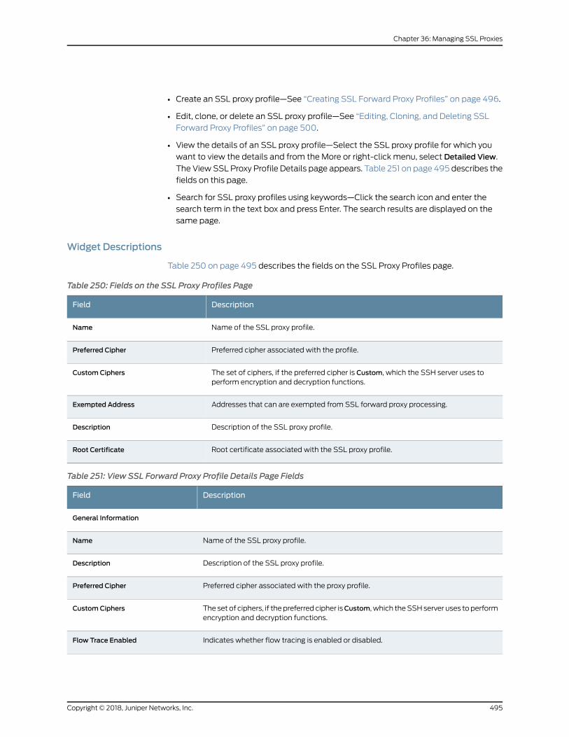
• Create an SSL proxy profile—See “Creating SSL Forward Proxy Profiles” on page 496.
• Edit, clone, or delete an SSL proxy profile—See “Editing, Cloning, and Deleting SSL
Forward Proxy Profiles” on page 500.
• View the details of an SSL proxy profile—Select the SSL proxy profile for which you
want to view the details and from the More or right-click menu, select Detailed View.
The ViewSSL Proxy Profile Details page appears. Table 251 on page 495 describes the
fields on this page.
• Search for SSL proxy profiles using keywords—Click the search icon and enter the
search term in the text box and press Enter. The search results are displayed on the
same page.
Widget Descriptions
Table 250 on page 495 describes the fields on the SSL Proxy Profiles page.
Table 250: Fields on the SSL Proxy Profiles Page
DescriptionField
Name of the SSL proxy profile.Name
Preferred cipher associated with the profile.Preferred Cipher
The set of ciphers, if the preferred cipher is Custom, which the SSH server uses toperform encryption and decryption functions.
CustomCiphers
Addresses that can are exempted from SSL forward proxy processing.Exempted Address
Description of the SSL proxy profile.Description
Root certificate associated with the SSL proxy profile.Root Certificate
Table 251: View SSL Forward Proxy Profile Details Page Fields
DescriptionField
General Information
Name of the SSL proxy profile.Name
Description of the SSL proxy profile.Description
Preferred cipher associated with the proxy profile.Preferred Cipher
The set of ciphers, if thepreferred cipher isCustom, which theSSHserver uses toperformencryption and decryption functions.
CustomCiphers
Indicates whether flow tracing is enabled or disabled.Flow Trace Enabled
495Copyright © 2018, Juniper Networks, Inc.
Chapter 36: Managing SSL Proxies
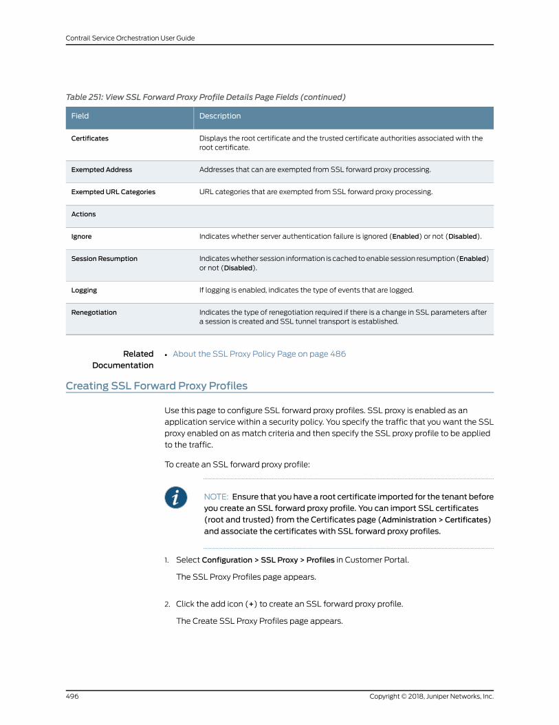
Table 251: View SSL Forward Proxy Profile Details Page Fields (continued)
DescriptionField
Displays the root certificate and the trusted certificate authorities associated with theroot certificate.
Certificates
Addresses that can are exempted from SSL forward proxy processing.Exempted Address
URL categories that are exempted from SSL forward proxy processing.Exempted URL Categories
Actions
Indicates whether server authentication failure is ignored (Enabled) or not (Disabled).Ignore
Indicateswhether session information is cached toenable session resumption (Enabled)or not (Disabled).
Session Resumption
If logging is enabled, indicates the type of events that are logged.Logging
Indicates the type of renegotiation required if there is a change in SSL parameters aftera session is created and SSL tunnel transport is established.
Renegotiation
RelatedDocumentation
About the SSL Proxy Policy Page on page 486•
Creating SSL Forward Proxy Profiles
Use this page to configure SSL forward proxy profiles. SSL proxy is enabled as an
application service within a security policy. You specify the traffic that you want the SSL
proxy enabled on as match criteria and then specify the SSL proxy profile to be applied
to the traffic.
To create an SSL forward proxy profile:
NOTE: Ensure that you have a root certificate imported for the tenant beforeyou create an SSL forward proxy profile. You can import SSL certificates(root and trusted) from the Certificates page (Administration > Certificates)
and associate the certificates with SSL forward proxy profiles.
1. Select Configuration > SSL Proxy > Profiles in Customer Portal.
The SSL Proxy Profiles page appears.
2. Click the add icon (+) to create an SSL forward proxy profile.
The Create SSL Proxy Profiles page appears.
Copyright © 2018, Juniper Networks, Inc.496
Contrail Service Orchestration User Guide
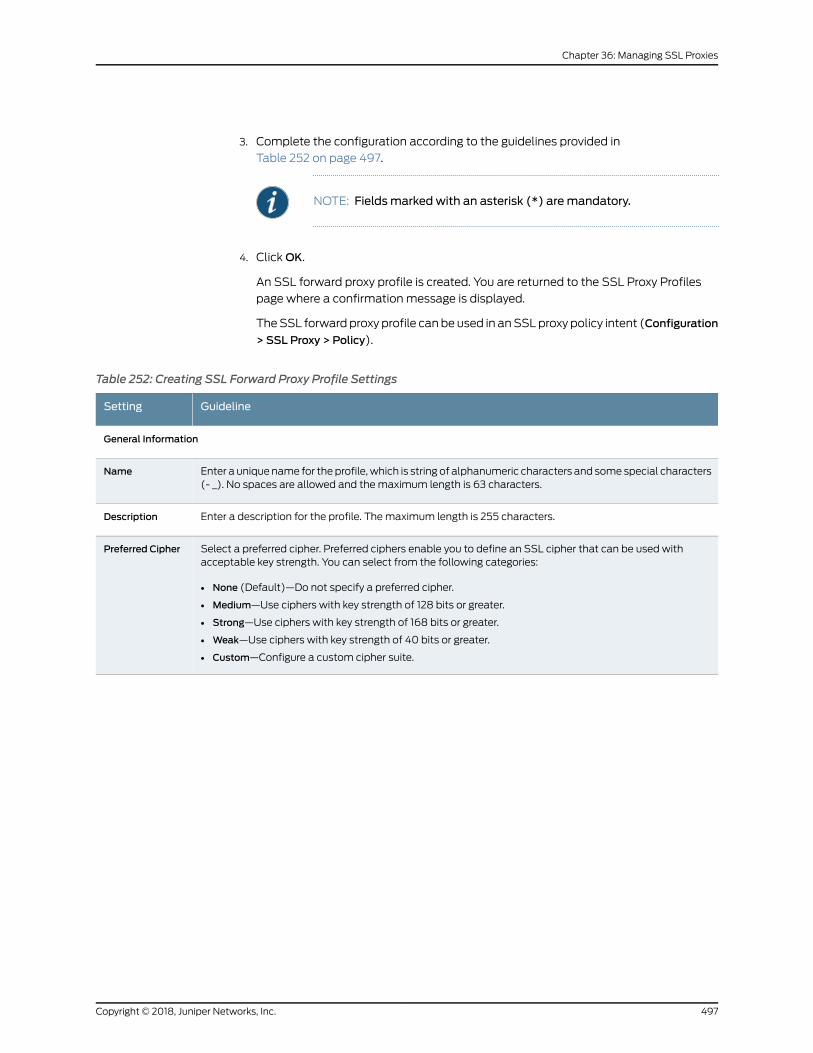
3. Complete the configuration according to the guidelines provided in
Table 252 on page 497.
NOTE: Fieldsmarked with an asterisk (*) aremandatory.
4. ClickOK.
An SSL forward proxy profile is created. You are returned to the SSL Proxy Profiles
page where a confirmation message is displayed.
TheSSL forward proxy profile canbe used in anSSLproxy policy intent (Configuration
> SSL Proxy > Policy).
Table 252: Creating SSL Forward Proxy Profile Settings
GuidelineSetting
General Information
Enter a unique name for the profile, which is string of alphanumeric characters and some special characters(- _). No spaces are allowed and themaximum length is 63 characters.
Name
Enter a description for the profile. Themaximum length is 255 characters.Description
Select a preferred cipher. Preferred ciphers enable you to define an SSL cipher that can be used withacceptable key strength. You can select from the following categories:
• None (Default)—Do not specify a preferred cipher.
• Medium—Use ciphers with key strength of 128 bits or greater.
• Strong—Use ciphers with key strength of 168 bits or greater.
• Weak—Use ciphers with key strength of 40 bits or greater.
• Custom—Configure a custom cipher suite.
Preferred Cipher
497Copyright © 2018, Juniper Networks, Inc.
Chapter 36: Managing SSL Proxies
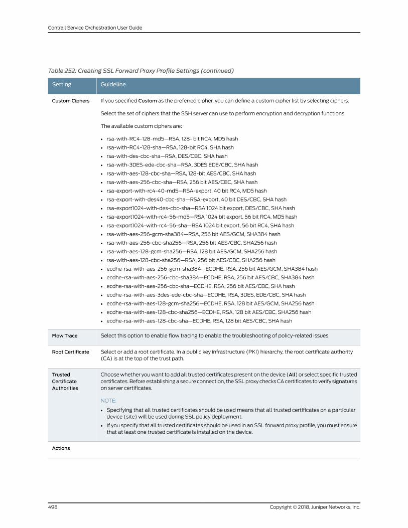
Table 252: Creating SSL Forward Proxy Profile Settings (continued)
GuidelineSetting
If you specified Custom as the preferred cipher, you can define a custom cipher list by selecting ciphers.
Select the set of ciphers that the SSH server can use to perform encryption and decryption functions.
The available custom ciphers are:
• rsa-with-RC4-128-md5—RSA, 128- bit RC4, MD5 hash
• rsa-with-RC4-128-sha—RSA, 128-bit RC4, SHA hash
• rsa-with-des-cbc-sha—RSA, DES/CBC, SHA hash
• rsa-with-3DES-ede-cbc-sha—RSA, 3DES EDE/CBC, SHA hash
• rsa-with-aes-128-cbc-sha—RSA, 128-bit AES/CBC, SHA hash
• rsa-with-aes-256-cbc-sha—RSA, 256 bit AES/CBC, SHA hash
• rsa-export-with-rc4-40-md5—RSA-export, 40 bit RC4, MD5 hash
• rsa-export-with-des40-cbc-sha—RSA-export, 40 bit DES/CBC, SHA hash
• rsa-export1024-with-des-cbc-sha—RSA 1024 bit export, DES/CBC, SHA hash
• rsa-export1024-with-rc4-56-md5—RSA 1024 bit export, 56 bit RC4, MD5 hash
• rsa-export1024-with-rc4-56-sha—RSA 1024 bit export, 56 bit RC4, SHA hash
• rsa-with-aes-256-gcm-sha384—RSA, 256 bit AES/GCM, SHA384 hash
• rsa-with-aes-256-cbc-sha256—RSA, 256 bit AES/CBC, SHA256 hash
• rsa-with-aes-128-gcm-sha256—RSA, 128 bit AES/GCM, SHA256 hash
• rsa-with-aes-128-cbc-sha256—RSA, 256 bit AES/CBC, SHA256 hash
• ecdhe-rsa-with-aes-256-gcm-sha384—ECDHE, RSA, 256 bit AES/GCM, SHA384 hash
• ecdhe-rsa-with-aes-256-cbc-sha384—ECDHE, RSA, 256 bit AES/CBC, SHA384 hash
• ecdhe-rsa-with-aes-256-cbc-sha—ECDHE, RSA, 256 bit AES/CBC, SHA hash
• ecdhe-rsa-with-aes-3des-ede-cbc-sha—ECDHE, RSA, 3DES, EDE/CBC, SHA hash
• ecdhe-rsa-with-aes-128-gcm-sha256—ECDHE, RSA, 128 bit AES/GCM, SHA256 hash
• ecdhe-rsa-with-aes-128-cbc-sha256—ECDHE, RSA, 128 bit AES/CBC, SHA256 hash
• ecdhe-rsa-with-aes-128-cbc-sha—ECDHE, RSA, 128 bit AES/CBC, SHA hash
CustomCiphers
Select this option to enable flow tracing to enable the troubleshooting of policy-related issues.Flow Trace
Select or add a root certificate. In a public key infrastructure (PKI) hierarchy, the root certificate authority(CA) is at the top of the trust path.
Root Certificate
Choosewhether youwant to addall trusted certificates present on thedevice (All) or select specific trustedcertificates. Beforeestablishingasecure connection, theSSLproxychecksCAcertificates to verify signatureson server certificates.
NOTE:
• Specifying that all trusted certificates should be usedmeans that all trusted certificates on a particulardevice (site) will be used during SSL policy deployment.
• If you specify that all trusted certificates should be used in an SSL forward proxy profile, youmust ensurethat at least one trusted certificate is installed on the device.
TrustedCertificateAuthorities
Actions
Copyright © 2018, Juniper Networks, Inc.498
Contrail Service Orchestration User Guide
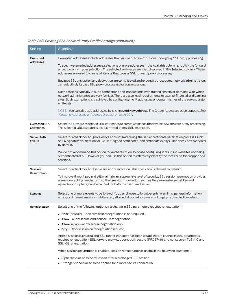
Table 252: Creating SSL Forward Proxy Profile Settings (continued)
GuidelineSetting
Exempted addresses include addresses that you want to exempt from undergoing SSL proxy processing.
Tospecifyexemptedaddressees, selectoneormoreaddresses in theAvailablecolumnandclick the forwardarrow to confirm your selection. The selected addresses are then displayed in the Selected column. Theseaddresses are used to create whitelists that bypass SSL forward proxy processing.
BecauseSSLencryptionanddecryptionare complicatedandexpensiveprocedures, networkadministratorscan selectively bypass SSL proxy processing for some sessions.
Such sessions typically include connections and transactions with trusted servers or domains with whichnetwork administrators are very familiar. There are also legal requirements to exempt financial and bankingsites. Such exemptions are achieved by configuring the IP addresses or domain names of the servers underwhitelists.
NOTE: You can also add addresses by clicking AddNewAddress. The Create Addresses page appears. See“Creating Addresses or Address Groups” on page 507.
ExemptedAddresses
Select the previously definedURL categories to createwhitelists that bypass SSL forward proxy processing.The selected URL categories are exempted during SSL inspection.
Exempted URLCategories
Select this check box to ignore errors encountered during the server certificate verification process (suchas CA signature verification failure, self-signed certificates, and certificate expiry). This check box is clearedby default.
We do not recommend this option for authentication, because configuring it results in websites not beingauthenticated at all. However, you can use this option to effectively identify the root cause for dropped SSLsessions.
Server AuthFailure
Select this check box to disable session resumption. This check box is cleared by default.
To improve throughput and still maintain an appropriate level of security, SSL session resumption providesa session-caching mechanism so that session information, such as the pre-master secret key andagreed-upon ciphers, can be cached for both the client and server.
SessionResumption
Select one or more events to be logged. You can choose to log all events, warnings, general information,errors, or different sessions (whitelisted, allowed, dropped, or ignored). Logging is disabled by default.
Logging
Select one of the following options if a change in SSL parameters requires renegotiation:
• None (default)—Indicates that renegotiation is not required.
• Allow—Allow secure and nonsecure renegotiation.
• Allow-secure—Allow secure negotiation only.
• Drop—Drop session on renegotiation request.
After a session is created and SSL tunnel transport has been established, a change in SSL parametersrequires renegotiation. SSL forward proxy supports both secure (RFC 5746) and nonsecure (TLS v1.0 andSSL v3) renegotiation.
When session resumption is enabled, session renegotiation is useful in the following situations:
• Cipher keys need to be refreshed after a prolonged SSL session.
• Stronger ciphers need to be applied for a more secure connection.
Renegotiation
499Copyright © 2018, Juniper Networks, Inc.
Chapter 36: Managing SSL Proxies
RelatedDocumentation
About the SSL Proxy Policy Page on page 486•
Editing, Cloning, and Deleting SSL Forward Proxy Profiles
You can edit, clone, and delete SSL forward proxy profiles from the SSL Proxy Profiles
page. This topic has the following sections:
• Editing SSL Forward Proxy Profiles on page 500
• Cloning SSL Forward Proxy Profiles on page 500
• Deleting SSL Forward Proxy Profiles on page 501
Editing SSL Forward Proxy Profiles
Tomodify the parameters configured for an SSL forward proxy profile:
NOTE: If an SSL forward proxy profile is already used in an SSL proxy policyintent, we recommend that you do not modify the profile name. If you wantto create a profilewith a newname, clone the existing profile andmodify thename.
1. Select Configuration > SSL Proxy > Profiles.
TheSSLProxyProfilespageappears, displaying theexistingSSL forwardproxyprofiles.
2. Select the SSL forward proxy profile that you want to edit and click the edit icon
(pencil). Alternatively, right-click a profile and select Edit Profile.
The Edit SSL Proxy Profile page appears showing the same fields that are presented
when you create an SSL forward proxy profile.
3. Modify the SSL forward proxy profile fields as needed.
4. ClickOK to save your changes.
You are taken to the SSL Proxy Profiles page. A confirmation message appears,
indicating the status of the edit operation.
NOTE: If anSSL forwardproxyprofile that is associatedwithanSSLproxypolicy intent ismodified, youmust redeploy theSSLproxypolicy toensurethat the changes take effect on the site.
Cloning SSL Forward Proxy Profiles
Cloning enables you to easily create a newSSL forward proxy profile based on an existing
one.
Copyright © 2018, Juniper Networks, Inc.500
Contrail Service Orchestration User Guide
To clone an SSL forward proxy profile:
1. Select Configuration > SSL Proxy > Profiles.
TheSSLProxyProfilespageappearsdisplaying theexistingSSL forwardproxyprofiles.
2. Select the SSL forward proxy profile that you want to clone and selectMore > Clone.
Alternatively, right-click a profile and select Clone.
TheCloneSSLProxyProfilepageappears, showing thesame fields thatarepresented
when you create an SSL forward proxy profile.
3. Modify the SSL forward proxy profile fields as needed.
4. ClickOK to save your changes.
You are taken to the SSL Proxy Profiles page. A confirmation message appears,
indicating the status of the clone operation.
Deleting SSL Forward Proxy Profiles
To delete one or more SSL forward proxy profiles:
NOTE: If you try to delete an SSL forward proxy profile that is associatedwith an SSL proxy policy intent, a message is displayed indicating that theprofile cannot be deleted.
1. Select Configuration > SSL Proxy > Profiles.
TheSSLProxyProfilespageappears, displaying theexistingSSL forwardproxyprofiles.
2. Select one or more SSL forward proxy profiles that you want to delete and click the
delete icon (X). Alternatively, right-click a profile and select Delete SSL Proxy Profile.
An alert message appears asking you to confirm the delete operation.
3. Click Yes to delete the selected SSL forward proxy profiles.
A confirmation message appears indicating the status of the delete operation.
NOTE: If the deleted SSL forward proxy profile is associated with an SSLproxy policy intent, youmust redeploy the SSL proxy policy to ensure thatthe changes take effect on the site.
RelatedDocumentation
Creating SSL Forward Proxy Profiles on page 496•
• About the SSL Proxy Profiles Page on page 494
501Copyright © 2018, Juniper Networks, Inc.
Chapter 36: Managing SSL Proxies
Configuring and Deploying an SSL Forward Proxy Policy
The following is theworkflow for configuring and deploying an intent-basedSSL forward
proxy policy in CSO:
1. Obtain the root certificate and private key fromyour trusted certificate authority (CA).
2. Combine the root certificate and private key into a single file.
3. Import the certificate and private key file (on the Import Certificate page); see
“Importing a Certificate” on page 619.
4. (Optional) Install the importedcertificateononeormoresites (on the InstallCertificate
page); see “Installing and Uninstalling Certificates” on page 621.
5. Bydefault, Juniper Networks ships trusted certificates for sites that useHTTPS. These
certificatesare installedautomaticallybyCSOwhen thesite is successfullyprovisioned.
If you want to use additional trusted certificates, import and install the certificates as
explained in Step 3 and 4.
6. Create an SSL proxy profile (on the Create SSL Proxy Profiles) page; see “Creating
SSL Forward Proxy Profiles” on page 496.
NOTE:• Use the imported root certificatewhen you create theSSLproxy profile.
• For trustedcertificates, specify thatall trustedcertificateson thedeviceare used (select All in the Trusted Certificate Authorities field).
7. Create an SSL proxy policy intent that uses the SSL proxy profile that you created (on
the SSL Proxy Policy page); see “Creating SSL Proxy Policy Intents” on page 487.
8. Deploy the SSL proxy policy; see “Deploying Policies” on page 532.
Copyright © 2018, Juniper Networks, Inc.502
Contrail Service Orchestration User Guide
NOTE:• Ensure that the root and trusted certificates are imported into CSObefore the policy is deployed.
• If you have not installed the certificates referenced in the SSL proxyprofile, then they are automatically installedwhen the SSL proxy policyis deployed.
9. For Internet access fromanSRXSeries device by using the SSL proxy, ensure that you
import the root certificate (obtained inStep 1) into thebrowsersof theclientsaccessing
the Internet.
NOTE: If you do not import the certificate, the traffic does not go throughfor clients in the LAN segments.
RelatedDocumentation
• SSL Forward Proxy Overview on page 481
• Understanding How SSL Proxy Policy Intents Are Applied on page 492
503Copyright © 2018, Juniper Networks, Inc.
Chapter 36: Managing SSL Proxies

Copyright © 2018, Juniper Networks, Inc.504
Contrail Service Orchestration User Guide
CHAPTER 37
Managing Shared Objects
• Addresses and Address Groups Overview on page 505
• About the Addresses Page on page 506
• Creating Addresses or Address Groups on page 507
• Editing, Cloning, and Deleting Addresses and Address Groups on page 509
• Services and Service Groups Overview on page 511
• About the Services Page on page 511
• Creating Services and Service Groups on page 512
• Creating Protocols on page 514
• Editing and Deleting Protocols on page 517
• Editing, Cloning, and Deleting Services and Service Groups on page 518
• Application Signatures Overview on page 520
• About the Application Signatures Page on page 520
• Creating Application Signature Groups on page 521
• Editing, Cloning, and Deleting Application Signature Groups on page 522
• About the Departments Page on page 524
• Creating a Department on page 525
• Modifying a Department on page 526
• Deleting a Department on page 526
Addresses and Address Groups Overview
An address specifies an IP address or a hostname. You can create addresses that can
be used across all policies. Addresses are used in firewall and NAT services and apply to
the correspondingpolicies. If you knowonly thehostname, youenter it into theHostname
field and use the address resolution option to resolve it to an IP address. You can also
resolve an IP address to the corresponding hostname.
After you create an address, you can combine it with other addresses to form an address
group. Address groups are useful when you want to apply the same policy to multiple
addresses.
505Copyright © 2018, Juniper Networks, Inc.
Contrail Service Orchestration (CSO)manages its address book at the global level,
assigning objects to devices that are required to create policies. An address book is a
collection of addresses and address groups that are available in a security zone. If the
device is capable of using a global address book, CSO pushes address objects used in
the policies to the global address book of the device.
RelatedDocumentation
About the Addresses Page on page 506•
• Creating Addresses or Address Groups on page 507
• Editing, Cloning, and Deleting Addresses and Address Groups on page 509
About the Addresses Page
To access this page, select Configuration > Shared Objects > Addresses.
Use this page to create, edit, and delete addresses and address groups. Addresses and
address groups are used in firewall and NAT services. After you create an address, you
can combine itwith other addresses to formanaddress group. Address groups are useful
when you want to apply the same policy to multiple services.
Tasks You Can Perform
You can perform the following tasks from this page:
• Create an address or address group. See “Creating Addresses or Address Groups” on
page 507.
• Modify, clone, or deleteanaddressor address group. See “Editing, Cloning, andDeleting
Addresses and Address Groups” on page 509.
• View the configured parameters of an address or address group. Click the details icon
that appearswhen youhover over thenameof an imageor selectMore>DetailedView.
See “Viewing Object Details” on page 241.
• Show or hide columns about the address or address group. See “Sorting Objects” on
page 241.
• Search for an address or address group. See “Searching for Text in an Object Data
Table” on page 242.
Field Descriptions
Table 253 on page 506 provides guidelines on using the fields on the Addresses page.
Table 253: Fields on the Addresses Page
DescriptionField
View the name of the address or address group.Name
View the type of the address or address group.Type
Copyright © 2018, Juniper Networks, Inc.506
Contrail Service Orchestration User Guide
Table 253: Fields on the Addresses Page (continued)
DescriptionField
View the hostname of the address.Hostname
View the IP address associated with the address.IP Address
View the description provided about the address or address group when it was created.Description
RelatedDocumentation
Addresses and Address Groups Overview on page 505•
• Creating Addresses or Address Groups on page 507
• Editing, Cloning, and Deleting Addresses and Address Groups on page 509
Creating Addresses or Address Groups
Use theAddressespage to create addresses andaddress groups. Addresses andaddress
groupsareused in firewall andNATservices.After youcreateanaddress, youcancombine
it with other addresses to form an address group. Address groups are useful when you
want to apply the same policy to multiple services.
To create an address or address group:
1. Select Configure > Shared Objects > Addresses.
The Addresses page appears.
2. Click on the add icon (+).
The Create Addresses page appears.
3. Complete the configuration according to the guidelines provided in
Table 254 on page 507 and Table 255 on page 508.
4. ClickOK to save the changes. If youwant todiscard your changes, clickCancel instead.
A new address or address group with your configurations is created. You can use this
object in firewall or NAT policies.
Table 254: Fields on the Create Addresses Page
DescriptionField
Select Address or Address Group. If you select Address Group, then the screen changes so youcan select the addresses you want to include in your address group. Table 255 on page 508describes address group configuration parameters.
Object Type
507Copyright © 2018, Juniper Networks, Inc.
Chapter 37: Managing Shared Objects
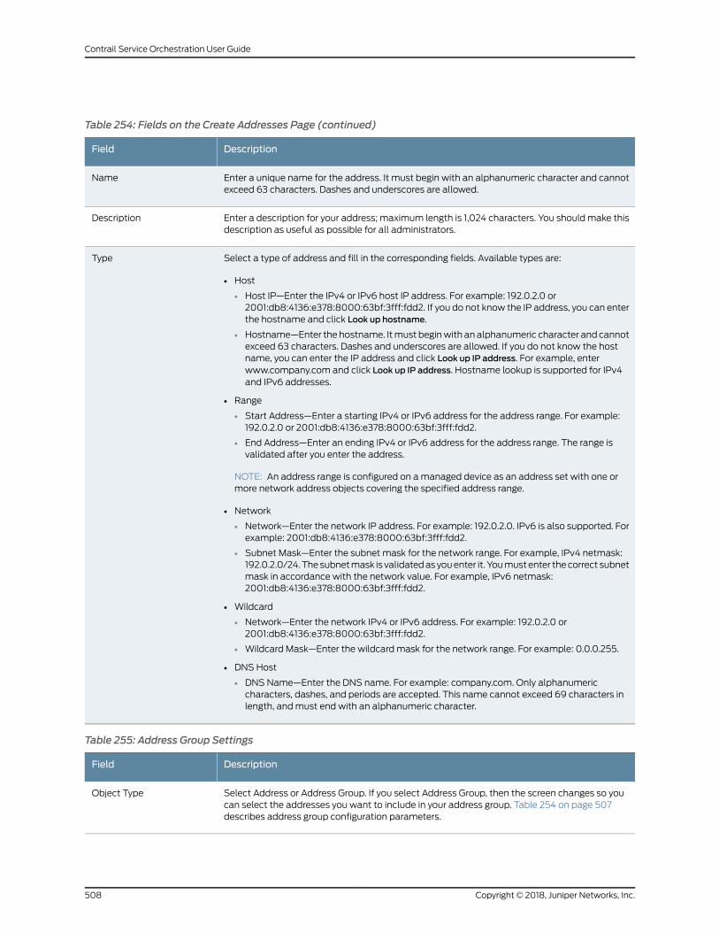
Table 254: Fields on the Create Addresses Page (continued)
DescriptionField
Enter a unique name for the address. It must begin with an alphanumeric character and cannotexceed 63 characters. Dashes and underscores are allowed.
Name
Enter a description for your address; maximum length is 1,024 characters. You should make thisdescription as useful as possible for all administrators.
Description
Select a type of address and fill in the corresponding fields. Available types are:
• Host
• Host IP—Enter the IPv4 or IPv6 host IP address. For example: 192.0.2.0 or2001:db8:4136:e378:8000:63bf:3fff:fdd2. If you do not know the IP address, you can enterthe hostname and click Look up hostname.
• Hostname—Enter the hostname. Itmust beginwith an alphanumeric character and cannotexceed 63 characters. Dashes and underscores are allowed. If you do not know the hostname, you can enter the IP address and click Look up IP address. For example, enterwww.company.com and click Look up IP address. Hostname lookup is supported for IPv4and IPv6 addresses.
• Range
• Start Address—Enter a starting IPv4 or IPv6 address for the address range. For example:192.0.2.0 or 2001:db8:4136:e378:8000:63bf:3fff:fdd2.
• End Address—Enter an ending IPv4 or IPv6 address for the address range. The range isvalidated after you enter the address.
NOTE: An address range is configured on amanaged device as an address set with one ormore network address objects covering the specified address range.
• Network
• Network—Enter the network IP address. For example: 192.0.2.0. IPv6 is also supported. Forexample: 2001:db8:4136:e378:8000:63bf:3fff:fdd2.
• Subnet Mask—Enter the subnet mask for the network range. For example, IPv4 netmask:192.0.2.0/24.Thesubnetmask is validatedasyouenter it. Youmustenter thecorrect subnetmask in accordance with the network value. For example, IPv6 netmask:2001:db8:4136:e378:8000:63bf:3fff:fdd2.
• Wildcard
• Network—Enter the network IPv4 or IPv6 address. For example: 192.0.2.0 or2001:db8:4136:e378:8000:63bf:3fff:fdd2.
• Wildcard Mask—Enter the wildcard mask for the network range. For example: 0.0.0.255.
• DNS Host
• DNS Name—Enter the DNS name. For example: company.com. Only alphanumericcharacters, dashes, and periods are accepted. This name cannot exceed 69 characters inlength, andmust end with an alphanumeric character.
Type
Table 255: Address Group Settings
DescriptionField
Select Address or Address Group. If you select Address Group, then the screen changes so youcan select the addresses you want to include in your address group. Table 254 on page 507describes address group configuration parameters.
Object Type
Copyright © 2018, Juniper Networks, Inc.508
Contrail Service Orchestration User Guide
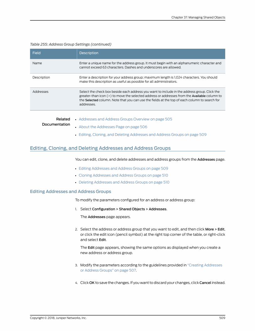
Table 255: Address Group Settings (continued)
DescriptionField
Enter a unique name for the address group. It must begin with an alphanumeric character andcannot exceed 63 characters. Dashes and underscores are allowed.
Name
Enter a description for your address group; maximum length is 1,024 characters. You shouldmake this description as useful as possible for all administrators.
Description
Select the check box beside each address you want to include in the address group. Click thegreater-than icon (>) to move the selected address or addresses from the Available column tothe Selected column. Note that you can use the fields at the top of each column to search foraddresses.
Addresses
RelatedDocumentation
Addresses and Address Groups Overview on page 505•
• About the Addresses Page on page 506
• Editing, Cloning, and Deleting Addresses and Address Groups on page 509
Editing, Cloning, and Deleting Addresses and Address Groups
You can edit, clone, and delete addresses and address groups from the Addresses page.
• Editing Addresses and Address Groups on page 509
• Cloning Addresses and Address Groups on page 510
• Deleting Addresses and Address Groups on page 510
Editing Addresses and Address Groups
Tomodify the parameters configured for an address or address group:
1. Select Configuration > Shared Objects > Addresses.
The Addresses page appears.
2. Select the address or address group that you want to edit, and then clickMore > Edit,
or click the edit icon (pencil symbol) at the right top corner of the table, or right-click
and select Edit.
The Edit page appears, showing the same options as displayed when you create a
new address or address group.
3. Modify the parameters according to the guidelines provided in “Creating Addresses
or Address Groups” on page 507.
4. ClickOK to save the changes. If youwant todiscard your changes, clickCancel instead.
509Copyright © 2018, Juniper Networks, Inc.
Chapter 37: Managing Shared Objects
When you clickOK, themodified address or address group is displayed on theAddresses
page.
NOTE: When you edit an address that is a deployed as part of a policy, youwill need to redeploy that policy in order for the changes to take effect. See“Deploying Policies” on page 532 for more information.
Cloning Addresses and Address Groups
To clone an address or address group:
1. Select Configuration > Shared Objects > Addresses.
The Addresses page appears.
2. Right-click the address or address group that you want to clone and then click Clone,
or selectMore > Clone.
The Clone page appears with editable fields.
3. Modify the configured parameters of the address or address group, as required.
4. ClickOK to save the changes. If youwant todiscard your changes, clickCancel instead.
If you selectOK, the cloned address or address group is saved.
Deleting Addresses and Address Groups
NOTE: Only addresses or address groups that have not been referenced inany policy can be deleted. If you try to delete such an address or addressgroup, an error message will be displayed.
To delete an address or address group:
1. Select Configuration > Shared Objects > Addresses.
The Addresses page appears.
2. Select the address or address group youwant to delete and then click the delete icon
(X) .
An alert message appears verifying that you want to delete your selection.
3. Click Yes to delete the address or address group. If you do not want to delete, click
Cancel instead.
Copyright © 2018, Juniper Networks, Inc.510
Contrail Service Orchestration User Guide
If you select Yes, the selected address or address group is deleted, unless it is referenced
in a policy.
RelatedDocumentation
Addresses and Address Groups Overview on page 505•
• About the Addresses Page on page 506
• Creating Addresses or Address Groups on page 507
• Viewing Object Details on page 14
• Sorting Objects on page 15
• Searching for Text in an Object Data Table on page 15
Services and Service Groups Overview
A service refers to an application on a device. For example, DomainNameService (DNS).
Services are based on protocols and ports used by an application, and when added to a
policy, a configured service can be applied across all devices. Services are candidates
for firewall policy end-points. The protocols used to create a service include: TCP, UDP,
MS-RPC,SUN-RPC, ICMP,and ICMPv6.ContrailServiceOrchestration(CSO)also includes
predefined, commonly used services, and you cannot modify or delete them.
Once you create a service, you can combine it with other services to forma service group.
Service groups are useful when you want to apply the same policy to multiple services,
as this enables you create fewer policies.
RelatedDocumentation
About the Services Page on page 511•
• Creating Services and Service Groups on page 512
• Editing, Cloning, and Deleting Services and Service Groups on page 518
About the Services Page
To access this page, select Configuration > Shared Objects > Services.
Use the Services page to create, modify, clone and delete service or service groups. You
can also create andmanage protocols, that you use to create services.
A service refers to an application on a device, such as Domain Name Service (DNS).
Services are based on protocols and ports used by an application. When added to a
policy, a configured service can be applied across all devices. The protocols available to
create a service include: TCP, UDP, SUN-RPC, MS-RPC, ICMP, ICMPv6, and so on.
511Copyright © 2018, Juniper Networks, Inc.
Chapter 37: Managing Shared Objects
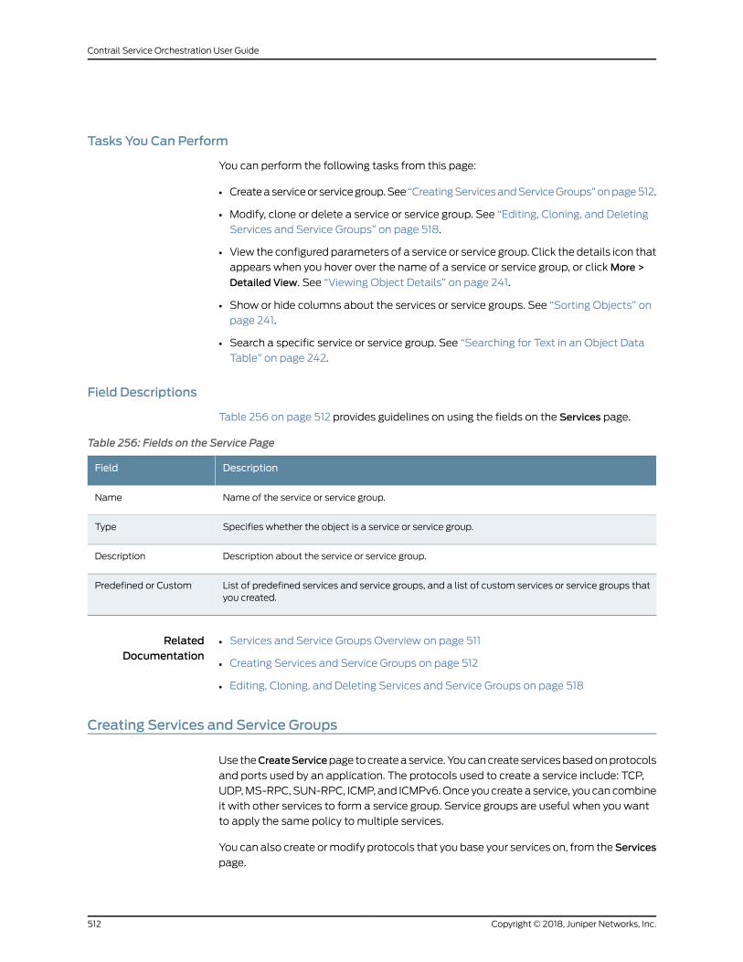
Tasks You Can Perform
You can perform the following tasks from this page:
• Createaserviceor servicegroup.See “CreatingServicesandServiceGroups”onpage512.
• Modify, clone or delete a service or service group. See “Editing, Cloning, and Deleting
Services and Service Groups” on page 518.
• View the configured parameters of a service or service group. Click the details icon that
appears when you hover over the name of a service or service group, or clickMore >
Detailed View. See “Viewing Object Details” on page 241.
• Show or hide columns about the services or service groups. See “Sorting Objects” on
page 241.
• Search a specific service or service group. See “Searching for Text in an Object Data
Table” on page 242.
Field Descriptions
Table 256 on page 512 provides guidelines on using the fields on the Services page.
Table 256: Fields on the Service Page
DescriptionField
Name of the service or service group.Name
Specifies whether the object is a service or service group.Type
Description about the service or service group.Description
List of predefined services and service groups, and a list of custom services or service groups thatyou created.
Predefined or Custom
RelatedDocumentation
Services and Service Groups Overview on page 511•
• Creating Services and Service Groups on page 512
• Editing, Cloning, and Deleting Services and Service Groups on page 518
Creating Services and Service Groups
Use theCreateServicepage tocreateaservice. Youcancreate servicesbasedonprotocols
and ports used by an application. The protocols used to create a service include: TCP,
UDP,MS-RPC, SUN-RPC, ICMP, and ICMPv6.Once you create a service, you can combine
it with other services to form a service group. Service groups are useful when you want
to apply the same policy to multiple services.
You can also create ormodify protocols that you base your services on, from theServices
page.
Copyright © 2018, Juniper Networks, Inc.512
Contrail Service Orchestration User Guide
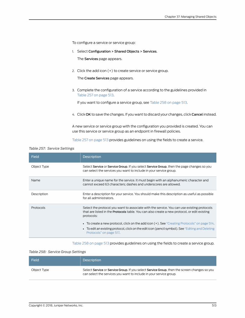
To configure a service or service group:
1. Select Configuration > Shared Objects > Services.
The Services page appears.
2. Click the add icon (+) to create service or service group.
The Create Services page appears.
3. Complete the configuration of a service according to the guidelines provided in
Table 257 on page 513.
If you want to configure a service group, see Table 258 on page 513.
4. ClickOK to save the changes. If youwant todiscard your changes, clickCancel instead.
A new service or service group with the configuration you provided is created. You can
use this service or service group as an endpoint in firewall policies.
Table 257 on page 513 provides guidelines on using the fields to create a service.
Table 257: Service Settings
DescriptionField
Select Service or Service Group. If you select Service Group, then the page changes so youcan select the services you want to include in your service group.
Object Type
Enter a unique name for the service. It must begin with an alphanumeric character andcannot exceed 63 characters; dashes and underscores are allowed.
Name
Enter a description for your service. You should make this description as useful as possiblefor all administrators.
Description
Select the protocol you want to associate with the service. You can use existing protocolsthat are listed in the Protocols table. You can also create a new protocol, or edit existingprotocols:
• To create a new protocol, click on the add icon (+). See “Creating Protocols” on page 514.
• Toedit anexistingprotocol, clickon theedit icon (pencil symbol). See “EditingandDeletingProtocols” on page 517.
Protocols
Table 258 on page 513 provides guidelines on using the fields to create a service group.
Table 258: Service Group Settings
DescriptionField
Select Service or Service Group. If you select Service Group, then the screen changes so youcan select the services you want to include in your service group.
Object Type
513Copyright © 2018, Juniper Networks, Inc.
Chapter 37: Managing Shared Objects
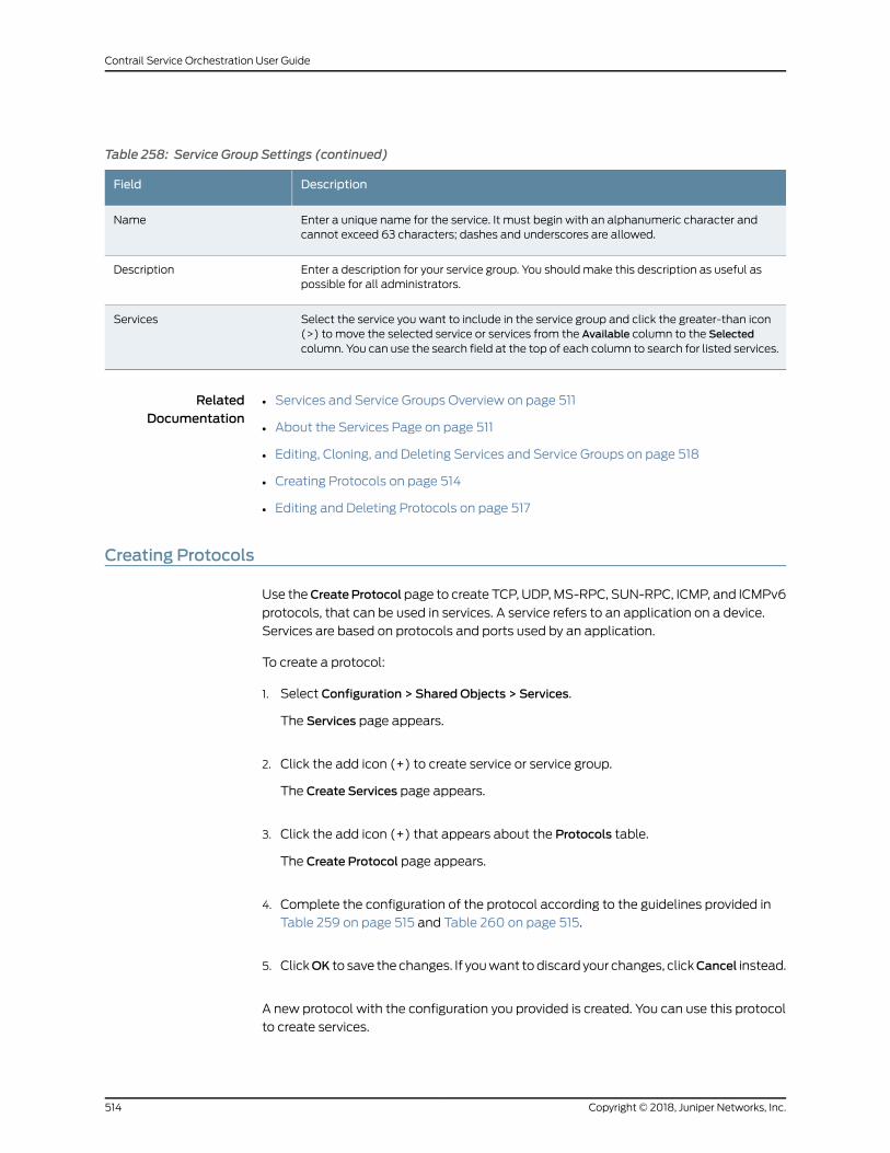
Table 258: Service Group Settings (continued)
DescriptionField
Enter a unique name for the service. It must begin with an alphanumeric character andcannot exceed 63 characters; dashes and underscores are allowed.
Name
Enter a description for your service group. You should make this description as useful aspossible for all administrators.
Description
Select the service you want to include in the service group and click the greater-than icon(>) to move the selected service or services from the Available column to the Selectedcolumn. You can use the search field at the top of each column to search for listed services.
Services
RelatedDocumentation
Services and Service Groups Overview on page 511•
• About the Services Page on page 511
• Editing, Cloning, and Deleting Services and Service Groups on page 518
• Creating Protocols on page 514
• Editing and Deleting Protocols on page 517
Creating Protocols
Use theCreateProtocol page to create TCP, UDP,MS-RPC, SUN-RPC, ICMP, and ICMPv6
protocols, that can be used in services. A service refers to an application on a device.
Services are based on protocols and ports used by an application.
To create a protocol:
1. Select Configuration > Shared Objects > Services.
The Services page appears.
2. Click the add icon (+) to create service or service group.
The Create Services page appears.
3. Click the add icon (+) that appears about the Protocols table.
The Create Protocol page appears.
4. Complete the configuration of the protocol according to the guidelines provided in
Table 259 on page 515 and Table 260 on page 515.
5. ClickOK to save the changes. If youwant todiscard your changes, clickCancel instead.
A new protocol with the configuration you provided is created. You can use this protocol
to create services.
Copyright © 2018, Juniper Networks, Inc.514
Contrail Service Orchestration User Guide
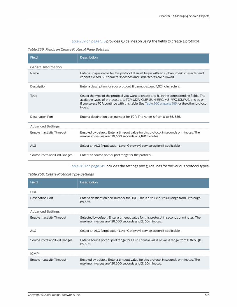
Table 259 on page 515 provides guidelines on using the fields to create a protocol.
Table 259: Fields on Create Protocol Page Settings
DescriptionField
General Information
Enter a unique name for the protocol. It must begin with an alphanumeric character andcannot exceed 63 characters; dashes and underscores are allowed.
Name
Enter a description for your protocol. It cannot exceed 1,024 characters.Description
Select the type of the protocol you want to create and fill in the corresponding fields. Theavailable types of protocols are: TCP, UDP, ICMP, SUN-RPC, MS-RPC, ICMPv6, and so on.If you select TCP, continue with this table. See Table 260 on page 515 for the other protocoltypes.
Type
Enter a destination port number for TCP. The range is from 0 to 65, 535.Destination Port
Advanced Settings
Enabled by default. Enter a timeout value for this protocol in seconds or minutes. Themaximum values are 129,600 seconds or 2,160minutes.
Enable Inactivity Timeout
Select an ALG (Application Layer Gateway) service option if applicable.ALG
Enter the source port or port range for the protocol.Source Ports and Port Ranges
Table 260onpage515 includes the settings andguidelines for the variousprotocol types.
Table 260: Create Protocol Type Settings
DescriptionField
UDP
Enter a destination port number for UDP. This is a value or value range from 0 through65,535.
Destination Port
Advanced Settings
Selected by default. Enter a timeout value for this protocol in seconds or minutes. Themaximum values are 129,600 seconds and 2,160minutes.
Enable Inactivity Timeout
Select an ALG (Application Layer Gateway) service option if applicable.ALG
Enter a source port or port range for UDP. This is a value or value range from 0 through65,535.
Source Ports and Port Ranges
ICMP
Enabled by default. Enter a timeout value for this protocol in seconds or minutes. Themaximum values are 129,600 seconds and 2,160minutes.
Enable Inactivity Timeout
515Copyright © 2018, Juniper Networks, Inc.
Chapter 37: Managing Shared Objects
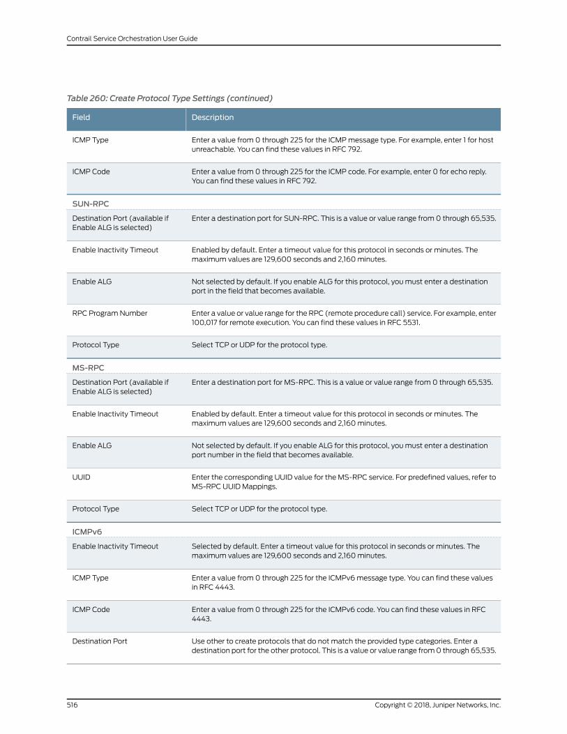
Table 260: Create Protocol Type Settings (continued)
DescriptionField
Enter a value from 0 through 225 for the ICMPmessage type. For example, enter 1 for hostunreachable. You can find these values in RFC 792.
ICMP Type
Enter a value from 0 through 225 for the ICMP code. For example, enter 0 for echo reply.You can find these values in RFC 792.
ICMP Code
SUN-RPC
Enter a destination port for SUN-RPC. This is a value or value range from 0 through 65,535.Destination Port (available ifEnable ALG is selected)
Enabled by default. Enter a timeout value for this protocol in seconds or minutes. Themaximum values are 129,600 seconds and 2,160minutes.
Enable Inactivity Timeout
Not selected by default. If you enable ALG for this protocol, you must enter a destinationport in the field that becomes available.
Enable ALG
Enter a value or value range for the RPC (remote procedure call) service. For example, enter100,017 for remote execution. You can find these values in RFC 5531.
RPC Program Number
Select TCP or UDP for the protocol type.Protocol Type
MS-RPC
Enter a destination port for MS-RPC. This is a value or value range from 0 through 65,535.Destination Port (available ifEnable ALG is selected)
Enabled by default. Enter a timeout value for this protocol in seconds or minutes. Themaximum values are 129,600 seconds and 2,160minutes.
Enable Inactivity Timeout
Not selected by default. If you enable ALG for this protocol, you must enter a destinationport number in the field that becomes available.
Enable ALG
Enter the corresponding UUID value for the MS-RPC service. For predefined values, refer toMS-RPC UUID Mappings.
UUID
Select TCP or UDP for the protocol type.Protocol Type
ICMPv6
Selected by default. Enter a timeout value for this protocol in seconds or minutes. Themaximum values are 129,600 seconds and 2,160minutes.
Enable Inactivity Timeout
Enter a value from 0 through 225 for the ICMPv6message type. You can find these valuesin RFC 4443.
ICMP Type
Enter a value from 0 through 225 for the ICMPv6 code. You can find these values in RFC4443.
ICMP Code
Use other to create protocols that do not match the provided type categories. Enter adestination port for the other protocol. This is a value or value range from0 through 65,535.
Destination Port
Copyright © 2018, Juniper Networks, Inc.516
Contrail Service Orchestration User Guide
RelatedDocumentation
Editing and Deleting Protocols on page 517•
• About the Services Page on page 511
• Creating Services and Service Groups on page 512
Editing and Deleting Protocols
You can edit and delete protocols through the Services page.
• Editing Protocols on page 517
• Deleting Protocols on page 518
Editing Protocols
Tomodify the parameters configured for a protocol:
1. Select Configuration > Shared Objects > Services .
The Services page appears.
2. Select the service to which the protocol you want to edit is associated, and click on
the edit icon (pencil symbol) on the right top corner of the table, or right-click and
select Edit Service.
The Edit Service page appears, listing the protocols associated with the service in
Protocols table.
3. Select theprotocol that youwant toedit, and thenclickon theedit icon (pencil symbol)
on the right top corner of the Protocols table, or right-click and select Edit Protocol.
The Edit Protocol page appears, showing the same fields as those seen when you
create a new protocol.
4. Modify theparametersof theprotocol according to theguidelinesprovided in “Creating
Protocols” on page 514.
5. ClickOK to save the changes. If youwant todiscard your changes, clickCancel instead.
If you clickOK, the modified protocol appears in the Protocols table.
517Copyright © 2018, Juniper Networks, Inc.
Chapter 37: Managing Shared Objects
Deleting Protocols
To delete a protocol:
1. Select Configuration > Shared Objects > Services.
The Services page appears.
2. Select the service to which the protocol you want to delete is associated, and click
on the edit icon (pencil symbol) on the right top corner of the table, or right-click and
select Edit Service.
The Edit Service page appears, listing the protocols associated with the service in
Protocols table.
3. Select the protocol you want to delete and then click the delete icon (X) .
An alert message appears, verifying that you want to delete the protocol.
4. Click Yes to delete the protocol. If you do not want to delete, click Cancel instead.
If you click Yes, the selected protocol is deleted.
RelatedDocumentation
Services and Service Groups Overview on page 511•
• About the Services Page on page 511
• Creating Services and Service Groups on page 512
• Editing, Cloning, and Deleting Services and Service Groups on page 518
• Creating Protocols on page 514
Editing, Cloning, and Deleting Services and Service Groups
You can edit, clone, and delete services and service groups from the Services page.
• Editing Services and Service Groups on page 518
• Cloning Services or Service Groups on page 519
• Deleting Services and Service Groups on page 519
Editing Services and Service Groups
Tomodify the parameters configured for a service or service group:
1. Select Configuration > Shared Objects > Services.
The Services page appears.
2. Select the service or service group that you want to edit, and click on the edit icon
(pencil symbol)on the right topcornerof the table, or right-clickandselectEditService.
Copyright © 2018, Juniper Networks, Inc.518
Contrail Service Orchestration User Guide
The Edit Service page appears, displaying the same options that are displayed when
creating a new service or service group.
3. Modify the parameters according to the guidelines provided in “Creating Services and
Service Groups” on page 512.
4. ClickOK to save the changes. If youwant todiscard your changes, clickCancel instead.
If you clickOK, you will see the modified service or service group in the Services page.
Cloning Services or Service Groups
To clone a service or service group:
1. Select Configuration > Shared Objects > Services.
The Services page appears.
2. Right-click on the service or service group that youwant to clone and then clickClone,
or selectMore > Clone.
The Clone Service page appears with editable fields.
3. ClickOK to save the changes. If youwant todiscard your changes, clickCancel instead.
If youclickOK, the clonedserviceor servicegroupwill appearbeneath the selectedservice
or service group.
Deleting Services and Service Groups
To delete a service or service group:
1. Select Configuration > Shared Objects > Services.
The Services page appears.
2. Select the service or service group you want to delete and then click the delete icon
(X) .
An alert message appears, verifying that you want to delete the service or service
group.
3. Click Yes to delete the service or service group. If you do not want to delete, click
Cancel instead.
If you click Yes, the selected service or service group is deleted.
RelatedDocumentation
Services and Service Groups Overview on page 511•
• About the Services Page on page 511
519Copyright © 2018, Juniper Networks, Inc.
Chapter 37: Managing Shared Objects
• Creating Services and Service Groups on page 512
Application Signatures Overview
JuniperNetworks regularlyupdates thepredefinedapplicationsignaturedatabase,making
it available to subscribers on the Juniper Networks website. This database includes
signaturedefinitionsof knownapplicationobjects thatcanbeused to identifyapplications
for tracking, firewall policies, and quality-of-service prioritization.
Use the Application Signatures page to get an overall, high-level view of your application
signature settings. You can filter and sort this information to get a better understanding
of what you want to configure.
RelatedDocumentation
About the Application Signatures Page on page 520•
• Creating Application Signature Groups on page 521
• Editing, Cloning, and Deleting Application Signature Groups on page 522
• Signature Database Overview on page 613
About the Application Signatures Page
To access this page, select Configuration > Shared Objects > Application Signatures.
Use the Application Signatures page to view application signatures that are already
downloadedand tocreate,modify, clone, anddeletecustomapplicationsignaturegroups.
TheApplicationSignaturespagedisplays thename,object type, categoryandsubcategory,
risk associated with, and characteristics of the signature. You can create custom
application signature groups with a set of similar signatures for consistent reuse when
defining policies.
Tasks You Can Perform
You can perform the following tasks from this page:
• Create an application signature group. See “Creating Application Signature Groups”
on page 521.
• Modify, clone, or delete an application signature group. See “Editing, Cloning, and
Deleting Application Signature Groups” on page 522.
• View the configured parameters of an application signature or application signature
group. Click the details icon that appears when you hover over the name of an image
or clickMore > Details. See “Viewing Object Details” on page 241.
• Showor hide columns in theApplicationSignatures. See “SortingObjects” onpage 241.
Copyright © 2018, Juniper Networks, Inc.520
Contrail Service Orchestration User Guide
• Search foraspecificapplicationsignatureorapplicationsignaturegroup.See “Searching
for Text in an Object Data Table” on page 242.
• Filter the application signature information based on select criteria. To do this, select
the filter icon at the top right-hand corner of the table. The columns in the grid change
to accept filter options. Select the filter options; the table displays only the data that
fits the filtering criteria.
Field Descriptions
Table 261onpage521providesguidelinesonusing the fieldson theApplicationSignatures
page.
Table 261: Fields on the Application Signatures Page
DescriptionField
Name of the application signature or application signature group.Name
Signature type—either application signature or application signature group.Object Type
UTM category of the application signature. For example, the value of Category can beMessaging,Web, Infrastructure, Remote-Access, Multimedia, and so on.
Category
UTMsubcategory of the application signature. For example, the value ofSubcategory can beWiki,File-Sharing, Multimedia, Social-Networking, News, and so on.
Subcategory
Level of risk associated with the application signature. For example, the value of Risk can be Low,High, unsafe, and so on.
Risk
One or more characteristics of the application signature.Characteristic
A list of predefined application signatures and application signature groups, and a list of customapplication signature groups that you created.
Predefined or Custom
RelatedDocumentation
Application Signatures Overview on page 520•
• Creating Application Signature Groups on page 521
• Editing, Cloning, and Deleting Application Signature Groups on page 522
• Signature Database Overview on page 613
• About the Active Database Page on page 614
Creating Application Signature Groups
Application identification supports customapplication signatures to detect applications
as they pass through the device. When you create custom signature groups, make sure
that your signature groups are unique, by providing a unique and relevant name.
521Copyright © 2018, Juniper Networks, Inc.
Chapter 37: Managing Shared Objects
To create an application signature group:
1. Select Configure > Shared Objects > Application Signatures.
2. Click the add icon (+).
3. Complete the configuration according to the guidelines provided in
Table 262 on page 522.
4. ClickOK to save the changes. If youwant todiscard your changes, clickCancel instead.
A new application signature group with your configurations is created. You can use this
application signature group in firewall, NAT, and SD-WAN policies.
Table 262 on page 522 provides guidelines on using the fields on the Create Application
Signature Group page.
Table 262: Fields on the Create Application Signature Group Page
DescriptionField
Enter a unique name that is a string of alphanumeric characters, colons, periods, dashes, andunderscores. No spaces are allowed and themaximum length is 63 characters.
Name
Click the add icon (+) to add signatures to your application group. On theAddApplicationSignaturespage, select the check boxes next to the signatures you want to add to the group.
Group Members
RelatedDocumentation
Application Signatures Overview on page 520•
• About the Application Signatures Page on page 520
• Editing, Cloning, and Deleting Application Signature Groups on page 522
• Signature Database Overview on page 613
• About the Active Database Page on page 614
Editing, Cloning, and Deleting Application Signature Groups
You can edit, clone, and delete application signature groups from the Application
Signatures page.
• Editing Application Signature Groups on page 523
• Cloning Application Signature Groups on page 523
• Deleting Application Signature Groups on page 523
Copyright © 2018, Juniper Networks, Inc.522
Contrail Service Orchestration User Guide
Editing Application Signature Groups
Tomodify the parameters configured for an application signature group:
1. Select Configuration > Shared Objects > Application Signatures.
The Application Signatures page appears.
2. Select the application signature group that you want to edit, and then selectMore >
Edit, or click on the edit icon (pencil symbol), on the top right corner of the table, or
right-click and select Edit.
TheEditpageappears, showing the sameoptionsas thosedisplayedwhen youcreate
a new application signature group.
3. Modify the parameters according to the guidelines provided in “Creating Application
Signature Groups” on page 521.
4. Click Save to save the changes. If you want to discard your changes, click Cancel
instead.
Themodified application signature group appears in the Application Signatures page.
Cloning Application Signature Groups
You can clone an application signature group when you want to reuse an existing
application signature group, but with a fewminor changes. This way, you can save time
recreating the application signature group from the start.
To clone an application signature group:
1. Select Configuration > Shared Objects > Application Signatures.
The Application Signatures page appears.
2. Right-click the application signature group that you want to clone and then select
Clone, or selectMore > Clone.
The Clone page appears with editable fields.
3. ClickOK to save the changes. If youwant todiscard your changes, clickCancel instead.
The cloned application signature group is displayed on the Application Signatures page.
Deleting Application Signature Groups
To delete an application signature group:
1. Select Configuration > Shared Objects > Application Signatures.
The Application Signatures page appears.
523Copyright © 2018, Juniper Networks, Inc.
Chapter 37: Managing Shared Objects
2. Select the application signature group you want to delete and then click the delete
icon (X) .
An alert message appears, verifying that you want to delete the selected item.
3. Click Yes to delete the selected application signature group. If you do not want to
delete, click Cancel instead.
RelatedDocumentation
Application Signatures Overview on page 520•
• About the Application Signatures Page on page 520
• Creating Application Signature Groups on page 521
• Signature Database Overview on page 613
About the Departments Page
To access this page, click Configuration > Network Services > Shared Objects >
Departments.
You can use the Departments page to create, view, edit, or delete departments. A
department is a grouping of LAN segments within a site. You use departments to apply
specific policies to LAN segments that are members of a department.
Tasks You Can Perform
You can perform the following tasks from this page:
• Create a Department. Click Configuration > Shared Objects > Departments > Create.
See “Creating a Department” on page 525.
• Edit a Department. Select a department and click Edit. See “Modifying a Department”
on page 526.
• Delete a department. Select a department and click Delete. Before you delete a
department, youmust reassign all the LAN segments that are assigned to the
department. You cannot delete a department that has a LAN segment assigned to it.
See “Deleting a Department” on page 526.
Field Descriptions
Table 263 on page 524 shows the descriptions of the fields on the Departments page.
Table 263: Fields on the Departments Page
DescriptionField
Displays the name of the department.Name
Displays the LAN segments that are assigned to the department.Site/LAN Segments
Copyright © 2018, Juniper Networks, Inc.524
Contrail Service Orchestration User Guide
Table 263: Fields on the Departments Page (continued)
DescriptionField
Displays the VPN to which the department is assigned.VPN
Displays a description of the department.Description
RelatedDocumentation
Creating a Department on page 525•
• Modifying a Department on page 526
• Deleting a Department on page 526
Creating a Department
Youcancreate newdepartments from theConfiguration>SharedObjects>Departments
page.
To create a department:
1. Click the add icon (+) on the Departments page.
The Create Department page appears.
2. Complete the configuration settings according to the guidelines provided
inTable 264 on page 525.
Table 264: Fields on the Create Departments Page
DescriptionField
Enter a name for the department. Enter a unique string of alphanumeric characters and somespecial characters (. -). No spaces are allowed and themaximum length is 15 characters.
Name
Enter a description of the department.Description
Select a VPN to which you want to assign the department.VPN
3. ClickOK.
The new department is displayed on the Departments page.
RelatedDocumentation
About the Departments Page on page 524•
• Modifying a Department on page 526
• Deleting a Department on page 526
525Copyright © 2018, Juniper Networks, Inc.
Chapter 37: Managing Shared Objects
Modifying a Department
Youcanmodify adepartmenton theConfiguration>SharedObjects>Departmentspage.
Tomodify a department:
1. Select a department and click the edit icon on the Departments page.
The Edit Department page appears.
2. Complete the configuration settings according to the guidelines provided
inTable 265 on page 526.
Table 265: Fields on the Edit Department Page
DescriptionField
Modify the name of the department, as needed.Name
Modify the description of the department.Description
Select a VPN to which you want to assign the department.VPN
3. ClickOK.
The updated department is displayed on the Departments page.
RelatedDocumentation
About the Departments Page on page 524•
• Creating a Department on page 525
• Deleting a Department on page 526
Deleting a Department
You can delete departments by clicking the delete icon (X) on the Departments page.
You can delete only one department at a time. You cannot delete a department if it has
policies associated with it or LAN segments assigned to it. Before you delete the
department, youmust reassign the LAN segments assigned to that department.
To delete a department:
1. Select the department that you want to delete.
2. Click the delete icon (X).
The Delete Department page appears.
3. ClickOK to confirm deletion.
Copyright © 2018, Juniper Networks, Inc.526
Contrail Service Orchestration User Guide
The department is deleted.
RelatedDocumentation
• About the Departments Page on page 524
• Creating a Department on page 525
• Modifying a Department on page 526
527Copyright © 2018, Juniper Networks, Inc.
Chapter 37: Managing Shared Objects

Copyright © 2018, Juniper Networks, Inc.528
Contrail Service Orchestration User Guide
CHAPTER 38
Managing Deployments
• Deploying Policies Overview on page 529
• About the Deployments Page on page 530
• Using the Deployment Icon to Deploy Policies on page 531
• Deploying Policies on page 532
Deploying Policies Overview
When you finish creating and verifying your security configurations, you can deploy these
configurations and keep them ready to be pushed to the security devices. CSO enables
you topushsecurity configurations to thedevicesall at oncebyprovidinga single interface
that is intuitive.
The deployment workflow provides the ability to save and publish different services to
be updated at a later time to the appropriate firewalls (during downtime). This enables
administrators to review their firewall and NAT policies before updating the device.
Administrators also save troubleshooting time, avoid errors, and save costs associated
with errors. Verify and tweak your security configurations before updating them to the
device. This approach helps you keep the configurations ready and update these
configurations to the devices during the maintenance window.
When you deploy policies, the process takes into account the priority and precedence
values set on the policy and the order of rules on the device. Rules are published in the
order of their priority groups.
If you change the priority or precedence of a published policy, the policy must be
republished for the changes to take effect. Sometimes, changing priority or precedence
inonepolicy canaffectotherpolicies in the samepriority group.However, suchdependent
policies do not need to be republished in order for their changes in priority or precedence
to take effect. It will be enough if the policy which is updated is republished.
There are three ways in which you can view and deploy your security configurations:
• Click on the deployment icon present in the CSO Customer Portal banner and use the
deployment panel that appears, to deploy policies. See “Using the Deployment Icon
to Deploy Policies” on page 531.
529Copyright © 2018, Juniper Networks, Inc.
NOTE: Thedeployment icon ishighlighted inorange if thereareundeployedconfigurations.
• Use the Deployments page. See “About the Deployments Page” on page 530.
• Select a firewall, NAT or SD-WAN policy from its respective landing pages and click
Deploy. For more information, see “Deploying Policies” on page 532.
RelatedDocumentation
Using the Deployment Icon to Deploy Policies on page 531•
• About the Deployments Page on page 530
• Deploying Policies on page 532
About the Deployments Page
To access this page, click Configuration > Deployments.
Use this page to deploy or schedule the deployment of undeployed SD-WAN, NAT, and
firewall policies. Undeployed policies refer to newly created firewall policy rules or NAT
policies. These changes do not come into effect until the policies are deployed. The
Deploy page provides scheduling options for you to deploy these policies.
Tasks You Can Perform
You can perform the following task from this page:
• Deploy a policy. See “Deploying Policies” on page 532.
Field Descriptions
Table 266 on page 530 provides guidelines on using the fields on theDeployments page.
Table 266: Fields on the Deployments Page
DescriptionField
The Awaiting Deployment tab displays all the policies that are awaiting deployment. The following fieldsprovide more information about the undeployed policies:
• Name—Name of the policy that needs to be deployed.
• Deployment Type—Type of the policy that needs to be deployed.
• Summary—Description of the policy.
• Owner—The tenant who has created the policy.
• Last updated—The last time the policy was updated.
If you want to deploy a policy, select the policy and click Deploy. The policy is deployed and will no longerappear in the Awaiting Deployment tab.
If you want to refresh the Awaiting Deployment tab, click the refresh icon provided below the details table.
AwaitingDeployment
Copyright © 2018, Juniper Networks, Inc.530
Contrail Service Orchestration User Guide
Table 266: Fields on the Deployments Page (continued)
DescriptionField
The Scheduled tab displays all the policies that have been scheduled for deployment on a certain date andtime. The following fields provide more information about scheduled policies:
• Name—Name of the policy.
• Deployment Type—Type of the policy that needs to be deployed.
• Summary—Description of the policy.
• Schedule—The date and time at which the policy is scheduled to be deployed.
• Status—Displays whether the scheduled policy has been deployed or not.
• Next Run—Date and time when the scheduled deployments will be run.
If you want to deploy a scheduled policy immediately, select the policy and click Deploy Now. If you want tomodify the deployment schedule of a policy, select the policy and click the edit icon (pencil icon). TheDeploypage appears displaying the current scheduling information. See “Deploying Policies” on page 532, to updatethe schedule.
Scheduled
TheHistory tabdisplaysall thepolicies thathavebeendeployed.The following fieldsprovidemore informationabout deployed policies:
• Name—Name of the deployed policy.
• Deployment Type—Type of the deployed policy.
• Summary—Description of the policy.
• Status–Displays the status of the deployed policy.
• Job Details—Details of the job.
• Deployed On—Date and time the policy was deployed.
If youwant to redeploy a policy, select the policy and clickRe-Deploy. The policy is redeployed and theHistorytab details changes to reflect this information.
History
RelatedDocumentation
Deploying Policies Overview on page 529•
• Using the Deployment Icon to Deploy Policies on page 531
• Deploying Policies on page 532
Using the Deployment Icon to Deploy Policies
CSOprovides anoption of viewing anddeploying policies through thedeployment panel,
that appearswhen you click on the deployment icon. The deployment icon is highlighted
in orange if there are undeployed policies.
To deploy policies through the deployment panel:
1. Click the deployment icon on the Customer Portal banner.
The deployment panel appears. For information about the panel, see
Table 267 on page 532.
531Copyright © 2018, Juniper Networks, Inc.
Chapter 38: Managing Deployments
2. Hover over the policy youwant to deploy. TheDeploy option appears on the right side
of the policy.
3. Click Deploy to deploy the policy. For more information, see “Deploying Policies” on
page 532.
Table 267 on page 532 provides guidelines on using the fields on the deployment panel.
Table 267: Fields on the Deployment Panel
DescriptionField
The Awaiting Deployment tab displays all the policies that are awaiting deployment.AwaitingDeployment
The In Progress tab displays all the policies that are currently being deployed.In Progress
RelatedDocumentation
Deploying Policies Overview on page 529•
• About the Deployments Page on page 530
• Deploying Policies on page 532
Deploying Policies
You can deploy firewall, NAT, SD-WAN, and SSL proxy policies added by various services
immediately or schedule the deployment for a later date and time.
To configure a deployment:
1. You can initiate the deployment of a policy in the following ways:
• Select a policy from the Awaiting Deployment tab on the Deployments page and
click Deploy.
• Select a policy from the Scheduled tab on the Deployments page and click Deploy.
• Select a policy from the Scheduled tab on the History page and click Re-Deploy.
• Use the deployment icon on the Customer Portal banner. For more information
about deploying policies using the deployment icon, see “Using the Deployment
Icon to Deploy Policies” on page 531.
NOTE: The deployment icon is highlighted in orange if there areundeployed policies.
• Select Configuration > Firewall > Firewall Policy. The Firewall Policy page appears,
displaying the intents associated with the policy. Click Deploy.
• Select Configuration > NAT >NAT Policies and select the NAT policy you want to
deploy. Click Deploy.
Copyright © 2018, Juniper Networks, Inc.532
Contrail Service Orchestration User Guide
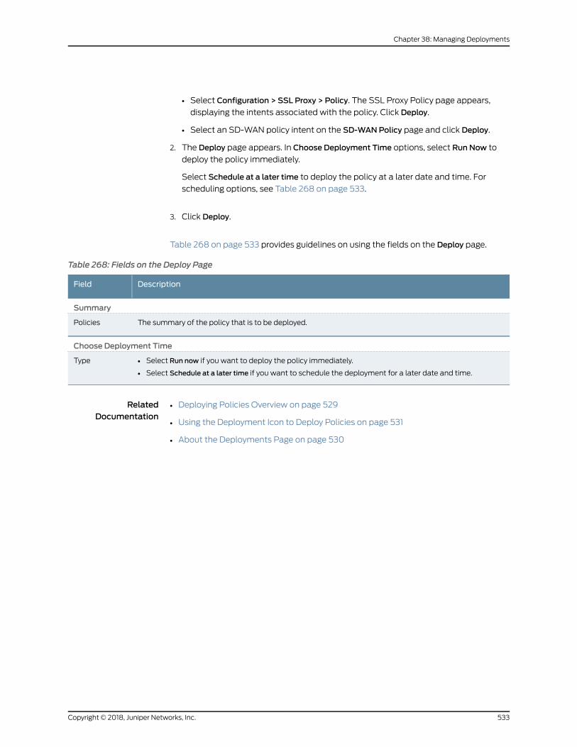
• Select Configuration > SSL Proxy > Policy. The SSL Proxy Policy page appears,
displaying the intents associated with the policy. Click Deploy.
• Select an SD-WAN policy intent on the SD-WANPolicy page and click Deploy.
2. The Deploy page appears. In Choose Deployment Time options, select Run Now to
deploy the policy immediately.
Select Schedule at a later time to deploy the policy at a later date and time. For
scheduling options, see Table 268 on page 533.
3. Click Deploy.
Table 268 on page 533 provides guidelines on using the fields on the Deploy page.
Table 268: Fields on the Deploy Page
DescriptionField
Summary
The summary of the policy that is to be deployed.Policies
Choose Deployment Time
• Select Run now if you want to deploy the policy immediately.
• Select Schedule at a later time if you want to schedule the deployment for a later date and time.
Type
RelatedDocumentation
• Deploying Policies Overview on page 529
• Using the Deployment Icon to Deploy Policies on page 531
• About the Deployments Page on page 530
533Copyright © 2018, Juniper Networks, Inc.
Chapter 38: Managing Deployments

Copyright © 2018, Juniper Networks, Inc.534
Contrail Service Orchestration User Guide
CHAPTER 39
Managing Sites
• About the Sites Page on page 535
• Local Breakout Overview on page 537
• Multihoming Overview on page 538
• Device Redundancy Support Overview on page 539
• Creating Spoke Sites for HybridWAN Deployment on page 541
• Creating Local Service Edge Sites for HybridWAN Deployment on page 543
• Creating Regional Service Edge Sites for HybridWAN Deployment on page 545
• Creating On-Premise Hub Sites for SD-WAN Deployment on page 547
• Creating On-Premise Spoke Sites for SD-WAN Deployment on page 549
• Creating Cloud Hub Sites for SD-WAN Deployment on page 554
• Creating Cloud Spoke Sites for SD-WAN Deployment on page 556
• Provisioning a Cloud Spoke Site in AWS VPC on page 561
• Importing Multiple Sites on page 565
• Managing a Single Site on page 566
• Configuring a Single Site on page 567
• Managing LAN Segments on a Tenant Site on page 570
• Activating a CPE Device on page 573
• Activating Dual CPE Devices (Device Redundancy) on page 576
• Viewing the History of Tenant Device Activation Logs on page 578
• Configuring VRFs and PNE Details for a Site in a Centralized Deployment on page 580
About the Sites Page
To access this page, click Sites > Site Management.
You canuse theSitespage to viewexisting sites and to create on-premise sites and cloud
sites. You can also use this page to view site configuration and device activation
information.
535Copyright © 2018, Juniper Networks, Inc.
Tasks You Can Perform
You can perform the following tasks from this page:
• View information about a site. Click the details icon that appears when you hover over
thenameofasiteorclickMore>DetailedView. See “ViewingObjectDetails”onpage241.
• Click on the site name to view the site details and to manage the site configurations
for a single site. See “Managing a Single Site” on page 566.
• Configure a site by uploading a JSON file. . See “Importing Multiple Sites” on page 565
• View device activation logs. Click Device Activation Logs. See “Viewing the History of
Tenant Device Activation Logs” on page 100.
• Create the following sites for a HybridWAN topology:
• Create a spoke site. See “Creating Spoke Sites for HybridWAN Deployment” on
page 541.
• Create a local service edge site. See “Creating Local Service Edge Sites for Hybrid
WAN Deployment” on page 543.
• Create a regional service edge site. See “Creating Regional Service Edge Sites for
HybridWAN Deployment” on page 545.
• Create the following sites for an SD-WAN topology:
• Create on-premise hub site. See “Creating On-Premise Hub Sites for SD-WAN
Deployment” on page 547.
• Create on-premise spoke site. See “Creating On-Premise Spoke Sites for SD-WAN
Deployment” on page 549.
• Create a cloud hub site. See “Creating Cloud Hub Sites for SD-WAN Deployment”
on page 554.
• Createacloudspokesite.See “CreatingCloudSpokeSites forSD-WANDeployment”
on page 556.
• Delete a site. Select a site and click the delete icon (X).
• Configure a site. Select a site and click Configure Site. See “Configuring a Single Site”
on page 567.
Field Descriptions
Table 269 on page 536 describes the fields on the Sites page.
Table 269: Fields on the Sites Page
DescriptionField
Displays the name of the tenant site.Site Name
Displays the location of the tenant site.Location
Copyright © 2018, Juniper Networks, Inc.536
Contrail Service Orchestration User Guide
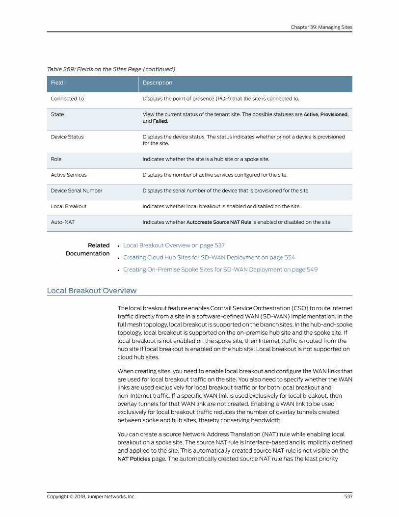
Table 269: Fields on the Sites Page (continued)
DescriptionField
Displays the point of presence (POP) that the site is connected to.Connected To
View the current status of the tenant site. The possible statuses are Active, Provisioned,and Failed.
State
Displays the device status. The status indicates whether or not a device is provisionedfor the site.
Device Status
Indicates whether the site is a hub site or a spoke site.Role
Displays the number of active services configured for the site.Active Services
Displays the serial number of the device that is provisioned for the site.Device Serial Number
Indicates whether local breakout is enabled or disabled on the site.Local Breakout
Indicates whether Autocreate Source NAT Rule is enabled or disabled on the site.Auto-NAT
RelatedDocumentation
Local Breakout Overview on page 537•
• Creating Cloud Hub Sites for SD-WAN Deployment on page 554
• Creating On-Premise Spoke Sites for SD-WAN Deployment on page 549
Local Breakout Overview
The localbreakout featureenablesContrail ServiceOrchestration (CSO) to route Internet
traffic directly from a site in a software-definedWAN (SD-WAN) implementation. In the
fullmesh topology, local breakout is supportedon thebranch sites. In thehub-and-spoke
topology, local breakout is supported on the on-premise hub site and the spoke site. If
local breakout is not enabled on the spoke site, then Internet traffic is routed from the
hub site if local breakout is enabled on the hub site. Local breakout is not supported on
cloud hub sites.
When creating sites, you need to enable local breakout and configure theWAN links that
are used for local breakout traffic on the site. You also need to specify whether theWAN
links are used exclusively for local breakout traffic or for both local breakout and
non-Internet traffic. If a specific WAN link is used exclusively for local breakout, then
overlay tunnels for thatWAN link are not created. Enabling aWAN link to be used
exclusively for local breakout traffic reduces the number of overlay tunnels created
between spoke and hub sites, thereby conserving bandwidth.
You can create a source Network Address Translation (NAT) rule while enabling local
breakout on a spoke site. The source NAT rule is interface-based and is implicitly defined
and applied to the site. This automatically created source NAT rule is not visible on the
NAT Policies page. The automatically created source NAT rule has the least priority
537Copyright © 2018, Juniper Networks, Inc.
Chapter 39: Managing Sites
among rules and can be overridden by a user-created NAT policy. The automatically
created source NAT rule can be enabled and disabled only from the Configuring a Site
page. For an on-premise hub site, the option for automatic creation of source NAT rule
is not available on the Configuring a Site page, and you need to create a source NAT rule.
YoucanenableSLAprofiles tobeassociatedwith local breakoutandmap theSLAprofile
to static SD-WAN policies. For SLA profiles that are used for local breakout, youmust
select a path preference. Static SD-WAN policies are used to route the traffic of the
applications defined in the static policies by using the preferred path in the attachedSLA
profile.
Applications are classified into the following categories:
• Cacheable applications—Cacheable applications are applications groups that are
stored in the application cache when they are recognized by the device. After they are
stored in the application cache, subsequent sessions are routed directly through the
correct WAN link. Only cacheable applications and application groups are supported
during the creation of local breakout-specific static SD-WAN policies.
• Noncacheable applications—Noncacheable applications are not stored in the
application cache and all sessions are first routed through the default path, and then
routed to thecorrectWANlinkbasedon theSD-WANpolicy.Noncacheableapplications
cannot be used for local breakout-specific static SD-WAN policies.
RelatedDocumentation
SLA Profiles and SD-WAN Policies Overview on page 437•
• Creating On-Premise Spoke Sites for SD-WAN Deployment on page 549
• Configuring a Single Site on page 567
• Creating SLA Profiles on page 447
Multihoming Overview
Multihoming is the ability of a spoke site to connect to two different hub devices in a hub
and spoke topology, thereby providing redundancy. The hub devices function as primary
and the secondary hub devices. If there aremultiple spokes in the system, the same hub
devicemayactasprimaryhubdevice foronespokeandsecondaryhubdevice foranother
spoke. That is, the selection of the primary and the secondary hub devices is only in the
context of a spoke site. The spoke is connected to both the hub devices through an
underlay network.
The hub devices can be MX series routers with an MS-MIC or SRX4000 series routers.
For a specific spoke site, both the hub devices must be either MX series routers or SRX
series routers. You cannot have one hub as an MX series router and another hub as an
SRX series router. To enable multihoming for a site, youmust select the hub and spoke
topology when you create the tenant. If you enable multihoming for a site, youmust
specify a primary and back up site when you configure the site.
Traffic is switched from the primary hub to the secondary hub in the following scenarios:
Copyright © 2018, Juniper Networks, Inc.538
Contrail Service Orchestration User Guide
• The primary hub is down
• The primary hub is up, but all the overlay tunnels between the spoke and the primary
hub are down
• The tunnels are up, but the iBGP session between the primary hub and vRR is down.
In this case, the failover occurs only after the BGP hold-time expires and the default
route is withdrawn.
NOTE: In addition to hub-level redundancy, you can provide VRR-levelredundancybycreatingtwoVRRs—primaryandsecondary—intwodifferentredundancy groups.
RelatedDocumentation
•
Device Redundancy Support Overview
Contrail Service Orchestration (CSO) provides support for spoke device redundancy for
large enterprise SD-WAN on-premise spoke sites. You can configure an SD-WAN site
with twoCPEdevices toactasprimaryandsecondarydevicesandprotect the siteagainst
device and link failures. If the primary device fails, the secondary device takes over the
traffic processing.
NOTE: Youmust use the samedevicemodel for bothprimary and secondarydevices and the devicesmust have the same version of Junos OS installed.
The following SD-WAN features are not supported for device redundancy:
• AppQOE (latency-optimized SLA)
• CPE in Full-mesh Topology
• LTEWAN backup link
• Service chain support
• Hub in Hub-Spoke Topology
NOTE: Device redundancy is supported only on SD-WAN deployments.
Prerequisites for SRX Series Devices
The prerequisites to configure an SD-WAN site with dual CPE SRX Series devices are as
follows:
539Copyright © 2018, Juniper Networks, Inc.
Chapter 39: Managing Sites
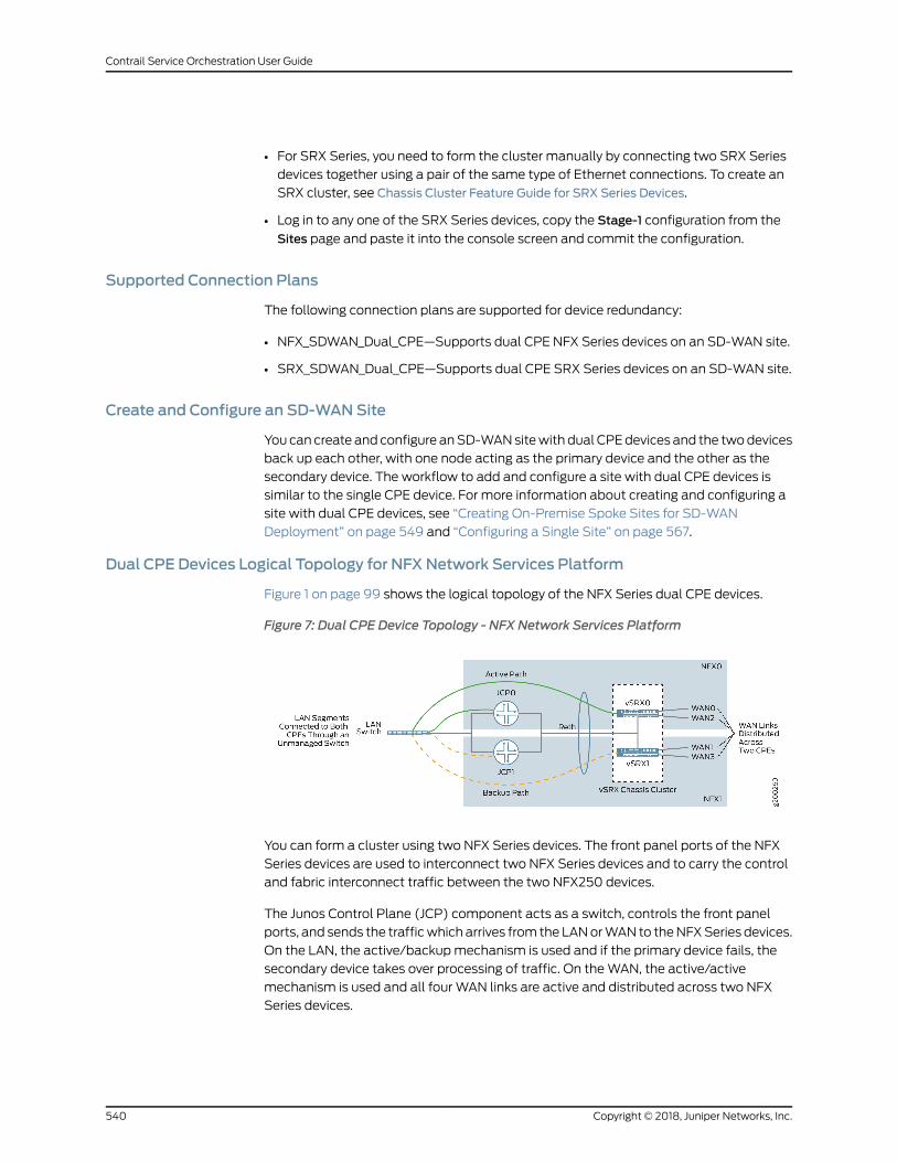
• For SRX Series, you need to form the cluster manually by connecting two SRX Series
devices together using a pair of the same type of Ethernet connections. To create an
SRX cluster, see Chassis Cluster Feature Guide for SRX Series Devices.
• Log in to any one of the SRX Series devices, copy the Stage-1 configuration from the
Sites page and paste it into the console screen and commit the configuration.
Supported Connection Plans
The following connection plans are supported for device redundancy:
• NFX_SDWAN_Dual_CPE—Supports dual CPE NFX Series devices on an SD-WAN site.
• SRX_SDWAN_Dual_CPE—Supports dual CPE SRX Series devices on an SD-WAN site.
Create and Configure an SD-WANSite
You can create and configure anSD-WANsitewith dual CPEdevices and the twodevices
back up each other, with one node acting as the primary device and the other as the
secondary device. The workflow to add and configure a site with dual CPE devices is
similar to the single CPE device. For more information about creating and configuring a
site with dual CPE devices, see “Creating On-Premise Spoke Sites for SD-WAN
Deployment” on page 549 and “Configuring a Single Site” on page 567.
Dual CPE Devices Logical Topology for NFX Network Services Platform
Figure 1 on page 99 shows the logical topology of the NFX Series dual CPE devices.
Figure 7: Dual CPE Device Topology - NFX Network Services Platform
You can form a cluster using two NFX Series devices. The front panel ports of the NFX
Series devices are used to interconnect two NFX Series devices and to carry the control
and fabric interconnect traffic between the two NFX250 devices.
The Junos Control Plane (JCP) component acts as a switch, controls the front panel
ports, and sends the trafficwhich arrives from the LANorWAN to theNFXSeries devices.
On the LAN, the active/backupmechanism is used and if the primary device fails, the
secondary device takes over processing of traffic. On theWAN, the active/active
mechanism is used and all four WAN links are active and distributed across two NFX
Series devices.
Copyright © 2018, Juniper Networks, Inc.540
Contrail Service Orchestration User Guide
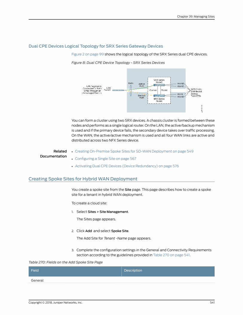
Dual CPE Devices Logical Topology for SRX Series Gateway Devices
Figure 2 on page 99 shows the logical topology of the SRX Series dual CPE devices.
Figure 8: Dual CPE Device Topology - SRX Series Devices
You can forma cluster using twoSRXdevices. A chassis cluster is formed between these
nodes andperformsas a single logical router. On the LAN, the active/backupmechanism
is used and if the primary device fails, the secondary device takes over traffic processing.
On theWAN, the active/active mechanism is used and all four WAN links are active and
distributed across two NFX Series device.
RelatedDocumentation
Creating On-Premise Spoke Sites for SD-WAN Deployment on page 549•
• Configuring a Single Site on page 567
• Activating Dual CPE Devices (Device Redundancy) on page 576
Creating Spoke Sites for HybridWANDeployment
You create a spoke site from the Site page. This page describes how to create a spoke
site for a tenant in hybridWAN deployment.
To create a cloud site:
1. Select Sites > Site Management.
The Sites page appears.
2. Click Add and select Spoke Site.
The Add Site for Tenant -Name page appears.
3. Complete the configuration settings in the General and Connectivity Requirements
section according to the guidelines provided in Table 270 on page 541.
Table 270: Fields on the Add Spoke Site Page
DescriptionField
General
541Copyright © 2018, Juniper Networks, Inc.
Chapter 39: Managing Sites
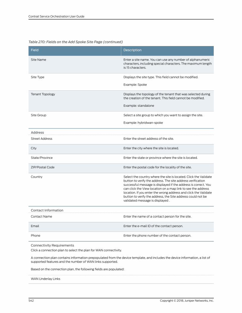
Table 270: Fields on the Add Spoke Site Page (continued)
DescriptionField
Enter a site name. You can use any number of alphanumericcharacters, including special characters. Themaximum lengthis 15 characters.
Site Name
Displays the site type. This field cannot bemodified.
Example: Spoke
Site Type
Displays the topology of the tenant that was selected duringthe creation of the tenant. This field cannot bemodified.
Example: standalone
Tenant Topology
Select a site group to which you want to assign the site.
Example: hybridwan-spoke
Site Group
Address
Enter the street address of the site.Street Address
Enter the city where the site is located.City
Enter the state or province where the site is located.State/Province
Enter the postal code for the locality of the site.ZIP/Postal Code
Select the country where the site is located. Click the Validatebutton to verify the address. The site address verificationsuccessful message is displayed if the address is correct. Youcan click the View location on amap link to see the addresslocation. If you enter the wrong address and click the Validatebutton to verify the address, the Site address could not bevalidatedmessage is displayed .
Country
Contact Information
Enter the name of a contact person for the site.Contact Name
Enter the e-mail ID of the contact person.Email
Enter the phone number of the contact person.Phone
Connectivity Requirements
Click a connection plan to select the plan for WAN connectivity.
A connection plan contains information prepopulated from the device template, and includes the device information, a list ofsupported features and the number of WAN links supported.
Based on the connection plan, the following fields are populated:
WAN Underlay Links
Copyright © 2018, Juniper Networks, Inc.542
Contrail Service Orchestration User Guide
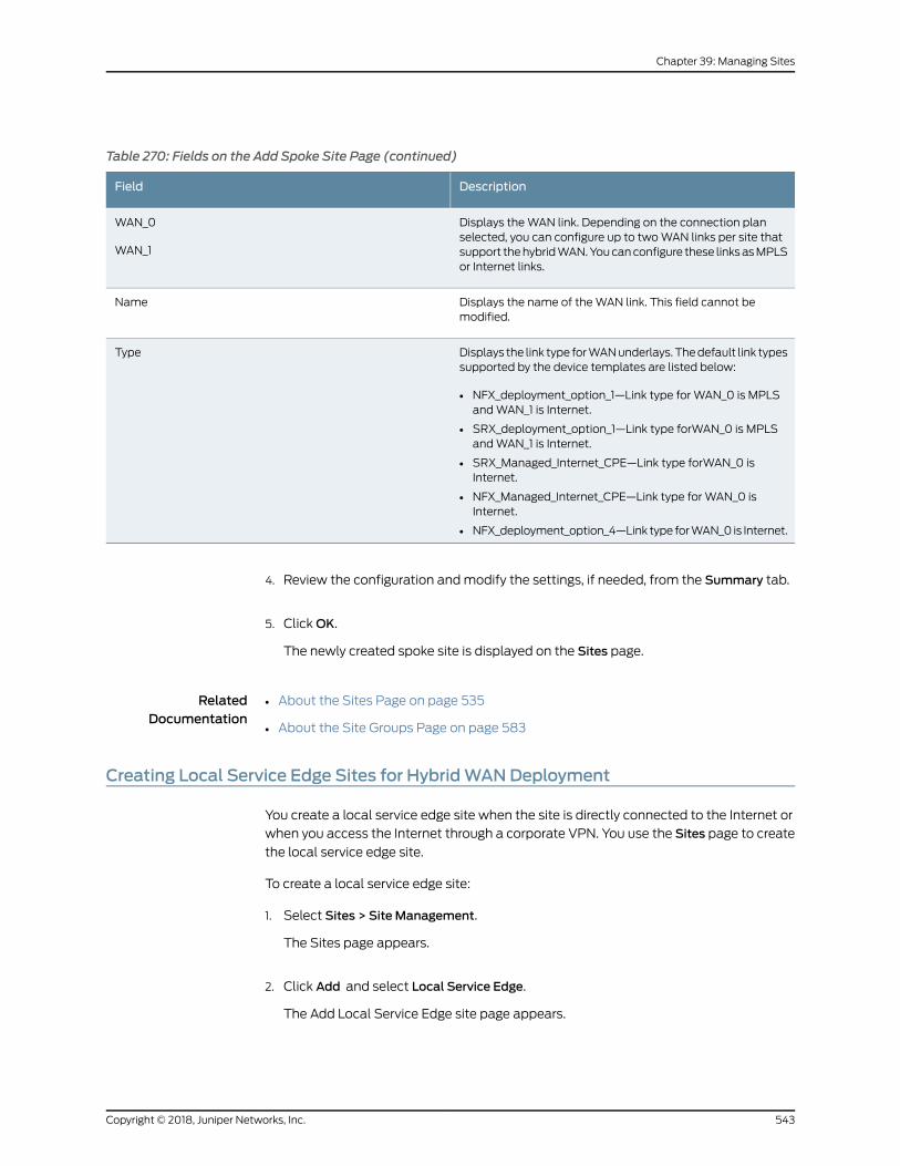
Table 270: Fields on the Add Spoke Site Page (continued)
DescriptionField
Displays theWAN link. Depending on the connection planselected, you can configure up to twoWAN links per site thatsupport thehybridWAN.Youcanconfigure these linksasMPLSor Internet links.
WAN_0
WAN_1
Displays the name of theWAN link. This field cannot bemodified.
Name
Displays the link type forWANunderlays.Thedefault link typessupported by the device templates are listed below:
• NFX_deployment_option_1—Link type for WAN_0 is MPLSandWAN_1 is Internet.
• SRX_deployment_option_1—Link type forWAN_0 is MPLSandWAN_1 is Internet.
• SRX_Managed_Internet_CPE—Link type forWAN_0 isInternet.
• NFX_Managed_Internet_CPE—Link type for WAN_0 isInternet.
• NFX_deployment_option_4—Link type forWAN_0 is Internet.
Type
4. Review the configuration andmodify the settings, if needed, from the Summary tab.
5. ClickOK.
The newly created spoke site is displayed on the Sites page.
RelatedDocumentation
About the Sites Page on page 535•
• About the Site Groups Page on page 583
Creating Local Service Edge Sites for HybridWANDeployment
You create a local service edge site when the site is directly connected to the Internet or
when you access the Internet through a corporate VPN. You use the Sites page to create
the local service edge site.
To create a local service edge site:
1. Select Sites > Site Management.
The Sites page appears.
2. Click Add and select Local Service Edge.
The Add Local Service Edge site page appears.
543Copyright © 2018, Juniper Networks, Inc.
Chapter 39: Managing Sites
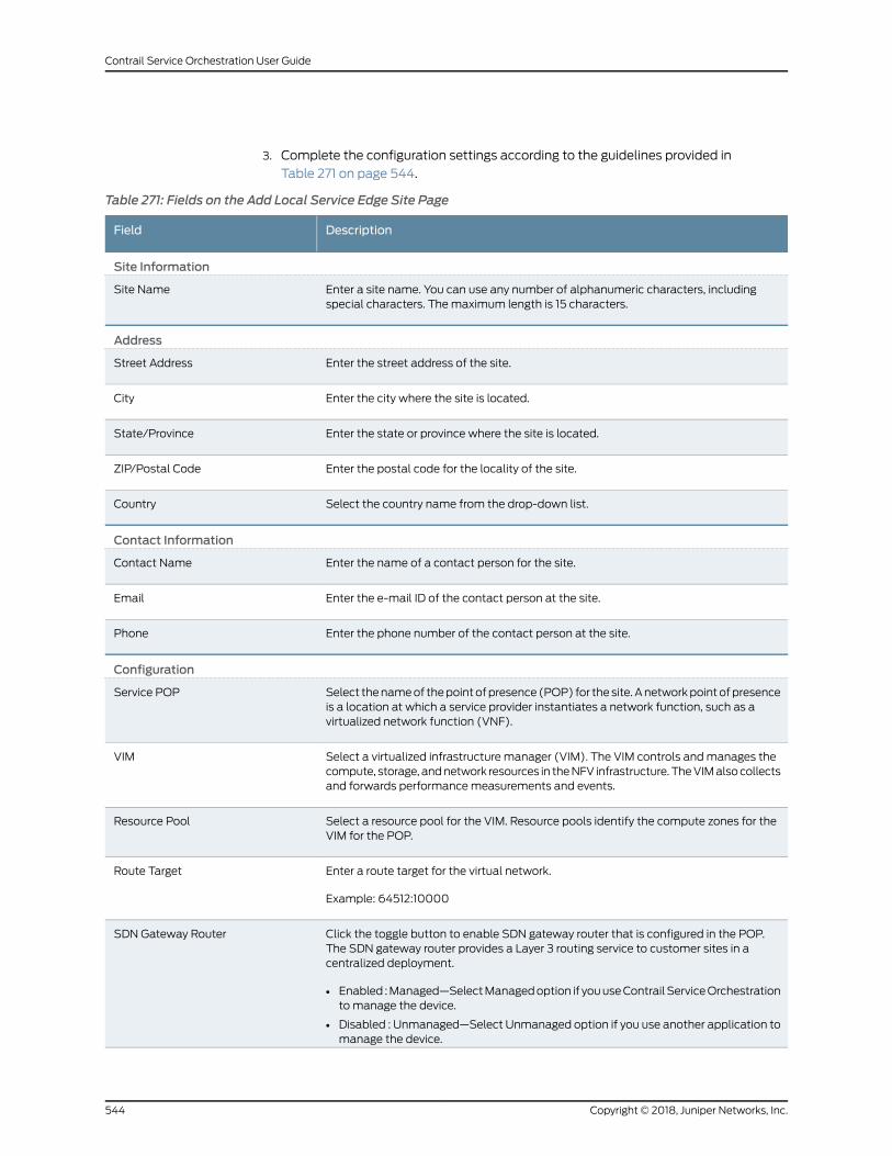
3. Complete the configuration settings according to the guidelines provided in
Table 271 on page 544.
Table 271: Fields on the Add Local Service Edge Site Page
DescriptionField
Site Information
Enter a site name. You can use any number of alphanumeric characters, includingspecial characters. Themaximum length is 15 characters.
Site Name
Address
Enter the street address of the site.Street Address
Enter the city where the site is located.City
Enter the state or province where the site is located.State/Province
Enter the postal code for the locality of the site.ZIP/Postal Code
Select the country name from the drop-down list.Country
Contact Information
Enter the name of a contact person for the site.Contact Name
Enter the e-mail ID of the contact person at the site.Email
Enter the phone number of the contact person at the site.Phone
Configuration
Select thenameof thepointofpresence (POP) for thesite.Anetworkpointofpresenceis a location at which a service provider instantiates a network function, such as avirtualized network function (VNF).
Service POP
Select a virtualized infrastructure manager (VIM). The VIM controls andmanages thecompute, storage, andnetwork resources in theNFV infrastructure. TheVIMalsocollectsand forwards performancemeasurements and events.
VIM
Select a resource pool for the VIM. Resource pools identify the compute zones for theVIM for the POP.
Resource Pool
Enter a route target for the virtual network.
Example: 64512:10000
Route Target
Click the toggle button to enable SDN gateway router that is configured in the POP.The SDN gateway router provides a Layer 3 routing service to customer sites in acentralized deployment.
• Enabled :Managed—SelectManagedoption if youuseContrail ServiceOrchestrationto manage the device.
• Disabled : Unmanaged—Select Unmanaged option if you use another application tomanage the device.
SDN Gateway Router
Copyright © 2018, Juniper Networks, Inc.544
Contrail Service Orchestration User Guide
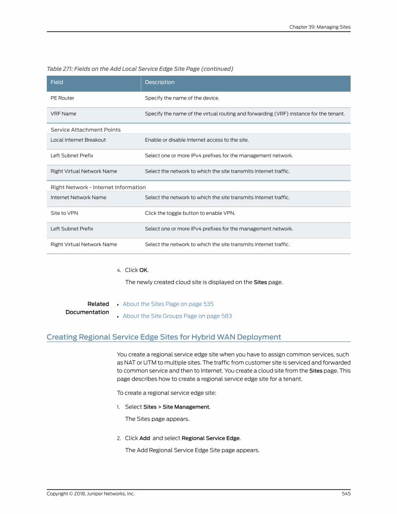
Table 271: Fields on the Add Local Service Edge Site Page (continued)
DescriptionField
Specify the name of the device.PE Router
Specify the name of the virtual routing and forwarding (VRF) instance for the tenant.VRF Name
Service Attachment Points
Enable or disable Internet access to the site.Local Internet Breakout
Select one or more IPv4 prefixes for the management network.Left Subnet Prefix
Select the network to which the site transmits Internet traffic.Right Virtual Network Name
Right Network - Internet Information
Select the network to which the site transmits Internet traffic.Internet Network Name
Click the toggle button to enable VPN.Site to VPN
Select one or more IPv4 prefixes for the management network.Left Subnet Prefix
Select the network to which the site transmits Internet traffic.Right Virtual Network Name
4. ClickOK.
The newly created cloud site is displayed on the Sites page.
RelatedDocumentation
About the Sites Page on page 535•
• About the Site Groups Page on page 583
Creating Regional Service Edge Sites for HybridWANDeployment
You create a regional service edge site when you have to assign common services, such
asNAT or UTM tomultiple sites. The traffic from customer site is serviced and forwarded
to common service and then to Internet. You create a cloud site from the Sites page. This
page describes how to create a regional service edge site for a tenant.
To create a regional service edge site:
1. Select Sites > Site Management.
The Sites page appears.
2. Click Add and select Regional Service Edge.
The Add Regional Service Edge Site page appears.
545Copyright © 2018, Juniper Networks, Inc.
Chapter 39: Managing Sites
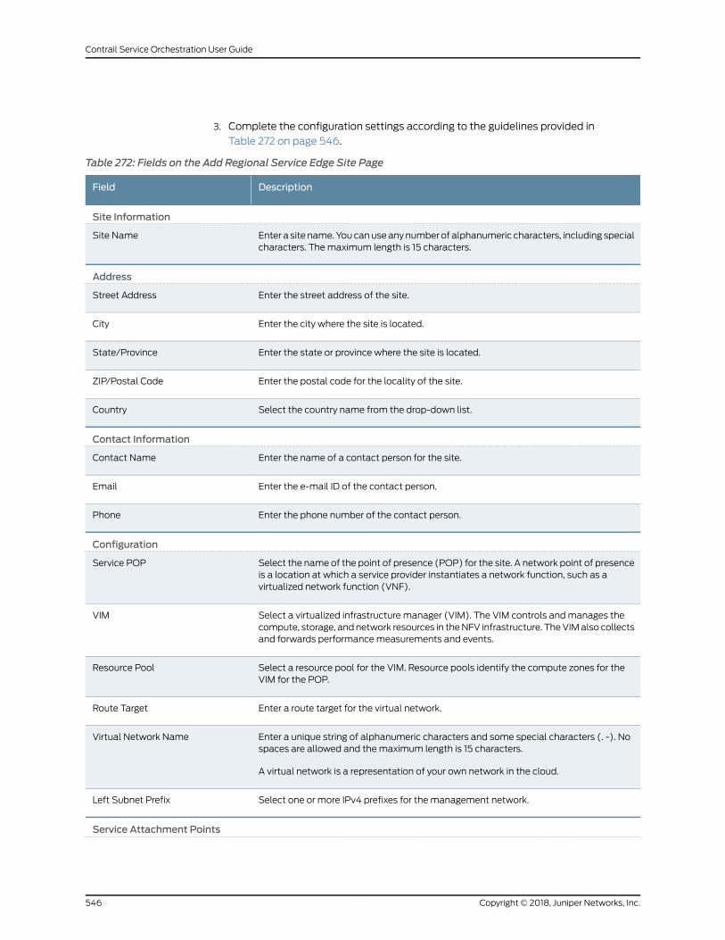
3. Complete the configuration settings according to the guidelines provided in
Table 272 on page 546.
Table 272: Fields on the Add Regional Service Edge Site Page
DescriptionField
Site Information
Enter a site name. Youcanuseanynumber of alphanumeric characters, including specialcharacters. Themaximum length is 15 characters.
Site Name
Address
Enter the street address of the site.Street Address
Enter the city where the site is located.City
Enter the state or province where the site is located.State/Province
Enter the postal code for the locality of the site.ZIP/Postal Code
Select the country name from the drop-down list.Country
Contact Information
Enter the name of a contact person for the site.Contact Name
Enter the e-mail ID of the contact person.Email
Enter the phone number of the contact person.Phone
Configuration
Select the name of the point of presence (POP) for the site. A network point of presenceis a location at which a service provider instantiates a network function, such as avirtualized network function (VNF).
Service POP
Select a virtualized infrastructure manager (VIM). The VIM controls andmanages thecompute, storage, andnetwork resources in theNFV infrastructure. TheVIMalso collectsand forwards performancemeasurements and events.
VIM
Select a resource pool for the VIM. Resource pools identify the compute zones for theVIM for the POP.
Resource Pool
Enter a route target for the virtual network.Route Target
Enter a unique string of alphanumeric characters and some special characters (. -). Nospaces are allowed and themaximum length is 15 characters.
A virtual network is a representation of your own network in the cloud.
Virtual Network Name
Select one or more IPv4 prefixes for the management network.Left Subnet Prefix
Service Attachment Points
Copyright © 2018, Juniper Networks, Inc.546
Contrail Service Orchestration User Guide
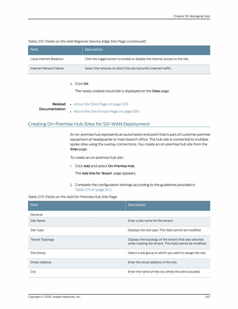
Table 272: Fields on the Add Regional Service Edge Site Page (continued)
DescriptionField
Click the toggle button to enable or disable the Internet access to the site.Local Internet Breakout
Select the network to which the site transmits Internet traffic.Internet Network Name
4. ClickOK.
The newly created cloud site is displayed on the Sites page.
RelatedDocumentation
About the Sites Page on page 535•
• About the Site Groups Page on page 583
Creating On-Premise Hub Sites for SD-WANDeployment
An on-premise hub represents an automation end point that is part of customer premise
equipment at headquarter or main branch office. The hub site is connected to multiple
spoke sites using the overlay connections. You create an on-premise hub site from the
Sites page.
To create an on-premise hub site:
1. Click Add and selectOn-Premise Hub.
The Add Site for Tenant page appears.
2. Complete the configuration settings according to the guidelines provided in
Table 273 on page 547.
Table 273: Fields on the Add On-Premise Hub Site Page
DescriptionField
General
Enter a site name for the tenant.Site Name
Displays the site type. This field cannot bemodified.Site Type
Displays the topology of the tenant that was selectedwhile creating the tenant. This field cannot bemodified.
Tenant Topology
Select a site group to which you want to assign the site.Site Group
Enter the street address of the site.Street Address
Enter the name of the city where the site is located.City
547Copyright © 2018, Juniper Networks, Inc.
Chapter 39: Managing Sites
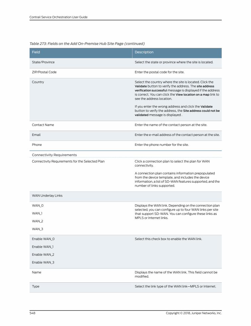
Table 273: Fields on the Add On-Premise Hub Site Page (continued)
DescriptionField
Select the state or province where the site is located.State/Province
Enter the postal code for the site.ZIP/Postal Code
Select the country where the site is located. Click theValidate button to verify the address. The site addressverification successfulmessage is displayed if the addressis correct. You can click the View location on amap link tosee the address location.
If you enter the wrong address and click the Validatebutton to verify the address, the Site address could not bevalidatedmessage is displayed .
Country
Enter the name of the contact person at the site.Contact Name
Enter the e-mail address of the contact person at the site.Email
Enter the phone number for the site.Phone
Connectivity Requirements
Click a connection plan to select the plan for WANconnectivity.
A connection plan contains information prepopulatedfrom the device template, and includes the deviceinformation, a list ofSD-WANfeatures supported, and thenumber of links supported.
Connectivity Requirements for the Selected Plan
WAN Underlay Links
Displays theWAN link. Depending on the connection planselected, you can configure up to four WAN links per sitethat support SD-WAN. You can configure these links asMPLS or Internet links.
WAN_0
WAN_1
WAN_2
WAN_3
Select this check box to enable theWAN link.EnableWAN_0
EnableWAN_1
EnableWAN_2
EnableWAN_3
Displays the name of theWAN link. This field cannot bemodified.
Name
Select the link type of theWAN link—MPLS or Internet.Type
Copyright © 2018, Juniper Networks, Inc.548
Contrail Service Orchestration User Guide
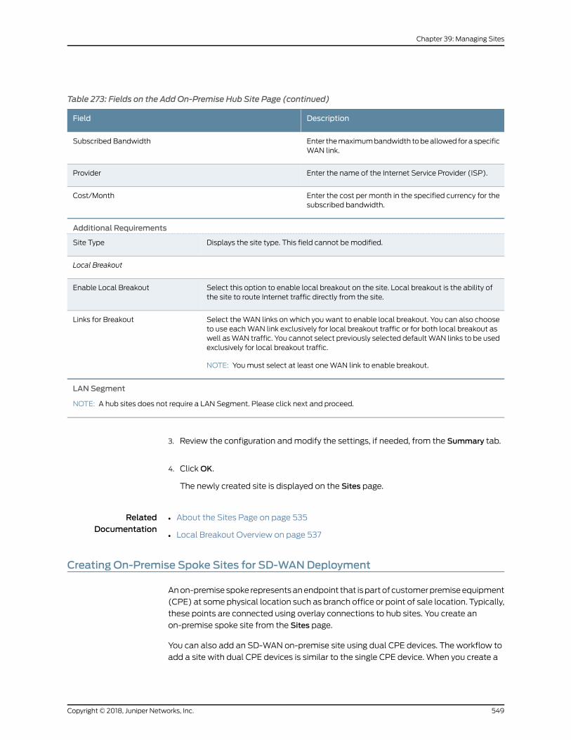
Table 273: Fields on the Add On-Premise Hub Site Page (continued)
DescriptionField
Enter themaximumbandwidth tobeallowed fora specificWAN link.
Subscribed Bandwidth
Enter the name of the Internet Service Provider (ISP).Provider
Enter the cost per month in the specified currency for thesubscribed bandwidth.
Cost/Month
Additional Requirements
Displays the site type. This field cannot bemodified.Site Type
Local Breakout
Select this option to enable local breakout on the site. Local breakout is the ability ofthe site to route Internet traffic directly from the site.
Enable Local Breakout
Select theWAN links on which you want to enable local breakout. You can also chooseto use eachWAN link exclusively for local breakout traffic or for both local breakout aswell asWAN traffic. You cannot select previously selected defaultWAN links to be usedexclusively for local breakout traffic.
NOTE: Youmust select at least oneWAN link to enable breakout.
Links for Breakout
LAN Segment
NOTE: A hub sites does not require a LAN Segment. Please click next and proceed.
3. Review the configuration andmodify the settings, if needed, from the Summary tab.
4. ClickOK.
The newly created site is displayed on the Sites page.
RelatedDocumentation
About the Sites Page on page 535•
• Local Breakout Overview on page 537
Creating On-Premise Spoke Sites for SD-WANDeployment
Anon-premisespoke representsanendpoint that ispartof customerpremiseequipment
(CPE) at some physical location such as branch office or point of sale location. Typically,
these points are connected using overlay connections to hub sites. You create an
on-premise spoke site from the Sites page.
You can also add an SD-WAN on-premise site using dual CPE devices. The workflow to
add a site with dual CPE devices is similar to the single CPE device. When you create a
549Copyright © 2018, Juniper Networks, Inc.
Chapter 39: Managing Sites
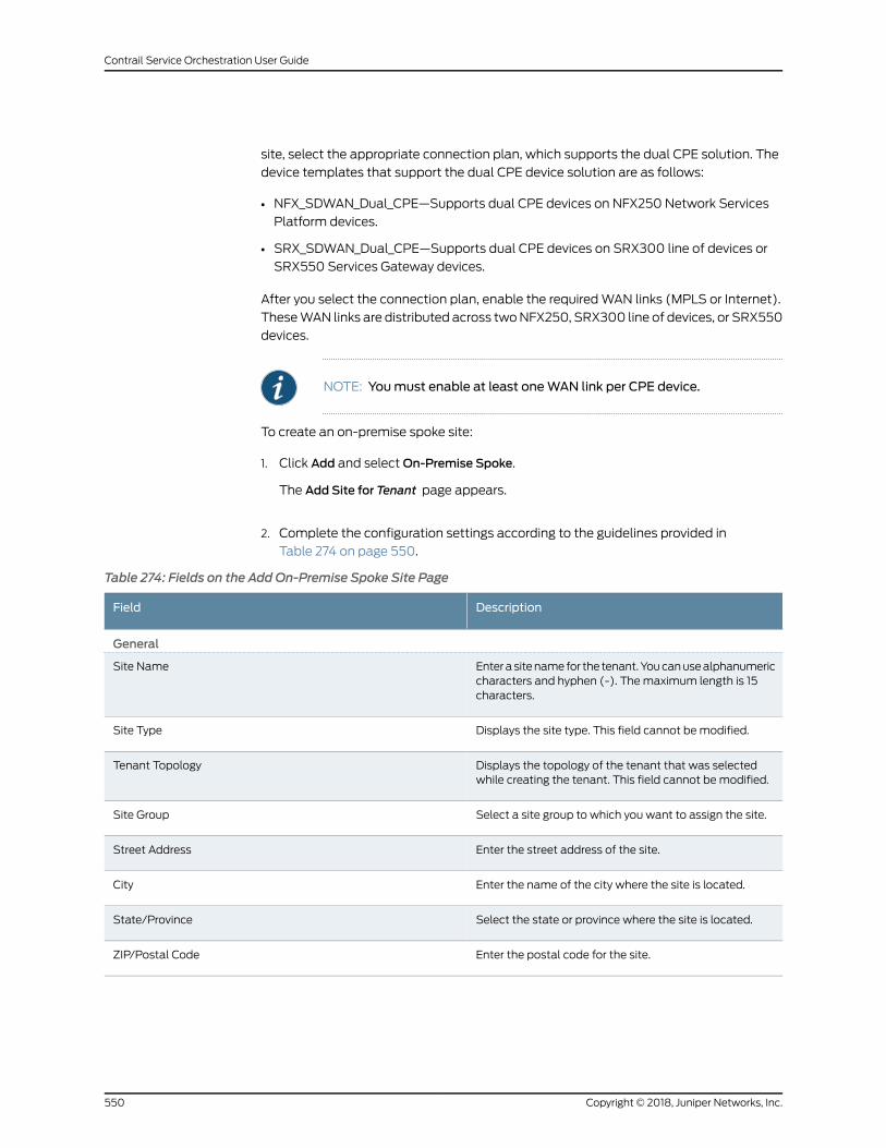
site, select the appropriate connection plan, which supports the dual CPE solution. The
device templates that support the dual CPE device solution are as follows:
• NFX_SDWAN_Dual_CPE—Supports dual CPE devices on NFX250 Network Services
Platform devices.
• SRX_SDWAN_Dual_CPE—Supports dual CPE devices on SRX300 line of devices or
SRX550 Services Gateway devices.
After you select the connection plan, enable the requiredWAN links (MPLS or Internet).
TheseWAN links are distributed across twoNFX250, SRX300 line of devices, or SRX550
devices.
NOTE: Youmust enable at least oneWAN link per CPE device.
To create an on-premise spoke site:
1. Click Add and selectOn-Premise Spoke.
The Add Site for Tenant page appears.
2. Complete the configuration settings according to the guidelines provided in
Table 274 on page 550.
Table 274: Fields on the Add On-Premise Spoke Site Page
DescriptionField
General
Enterasitenamefor the tenant.Youcanusealphanumericcharacters and hyphen (-). Themaximum length is 15characters.
Site Name
Displays the site type. This field cannot bemodified.Site Type
Displays the topology of the tenant that was selectedwhile creating the tenant. This field cannot bemodified.
Tenant Topology
Select a site group to which you want to assign the site.Site Group
Enter the street address of the site.Street Address
Enter the name of the city where the site is located.City
Select the state or province where the site is located.State/Province
Enter the postal code for the site.ZIP/Postal Code
Copyright © 2018, Juniper Networks, Inc.550
Contrail Service Orchestration User Guide
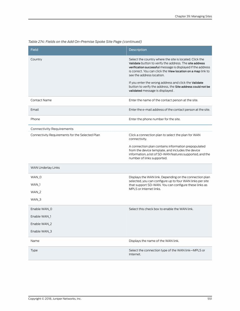
Table 274: Fields on the Add On-Premise Spoke Site Page (continued)
DescriptionField
Select the country where the site is located. Click theValidate button to verify the address. The site addressverification successfulmessage is displayed if the addressis correct. You can click the View location on amap link tosee the address location.
If you enter the wrong address and click the Validatebutton to verify the address, the Site address could not bevalidatedmessage is displayed .
Country
Enter the name of the contact person at the site.Contact Name
Enter the e-mail address of the contact person at the site.Email
Enter the phone number for the site.Phone
Connectivity Requirements
Click a connection plan to select the plan for WANconnectivity.
A connection plan contains information prepopulatedfrom the device template, and includes the deviceinformation, a list ofSD-WANfeatures supported, and thenumber of links supported.
Connectivity Requirements for the Selected Plan
WAN Underlay Links
Displays theWAN link. Depending on the connection planselected, you can configure up to four WAN links per sitethat support SD-WAN. You can configure these links asMPLS or Internet links.
WAN_0
WAN_1
WAN_2
WAN_3
Select this check box to enable theWAN link.EnableWAN_0
EnableWAN_1
EnableWAN_2
EnableWAN_3
Displays the name of theWAN link.Name
Select the connection type of theWAN link—MPLS orInternet.
Type
551Copyright © 2018, Juniper Networks, Inc.
Chapter 39: Managing Sites
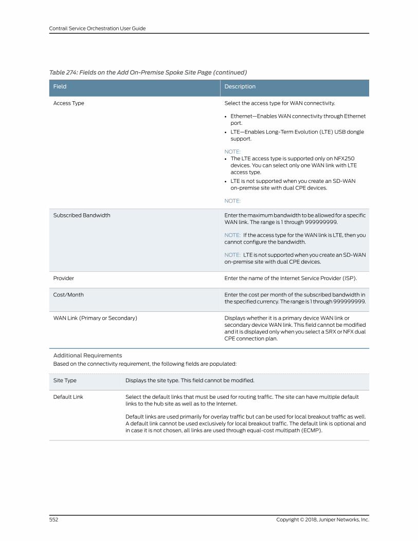
Table 274: Fields on the Add On-Premise Spoke Site Page (continued)
DescriptionField
Select the access type for WAN connectivity.
• Ethernet—EnablesWAN connectivity through Ethernetport.
• LTE—Enables Long-Term Evolution (LTE) USB donglesupport.
NOTE:• The LTE access type is supported only on NFX250devices. You can select only oneWAN link with LTEaccess type.
• LTE is not supported when you create an SD-WANon-premise site with dual CPE devices.
NOTE:
Access Type
Enter themaximumbandwidth tobeallowed fora specificWAN link. The range is 1 through 999999999.
NOTE: If the access type for theWAN link is LTE, then youcannot configure the bandwidth.
NOTE: LTE is not supportedwhen you create anSD-WANon-premise site with dual CPE devices.
Subscribed Bandwidth
Enter the name of the Internet Service Provider (ISP).Provider
Enter the cost per month of the subscribed bandwidth inthe specifiedcurrency. The range is 1 through999999999.
Cost/Month
Displays whether it is a primary deviceWAN link orsecondary deviceWAN link. This field cannot bemodifiedand it is displayedonlywhen you select aSRXorNFXdualCPE connection plan.
WAN Link (Primary or Secondary)
Additional Requirements
Based on the connectivity requirement, the following fields are populated:
Displays the site type. This field cannot bemodified.Site Type
Select the default links that must be used for routing traffic. The site can havemultiple defaultlinks to the hub site as well as to the Internet.
Default links are used primarily for overlay traffic but can be used for local breakout traffic as well.A default link cannot be used exclusively for local breakout traffic. The default link is optional andin case it is not chosen, all links are used through equal-cost multipath (ECMP).
Default Link
Copyright © 2018, Juniper Networks, Inc.552
Contrail Service Orchestration User Guide
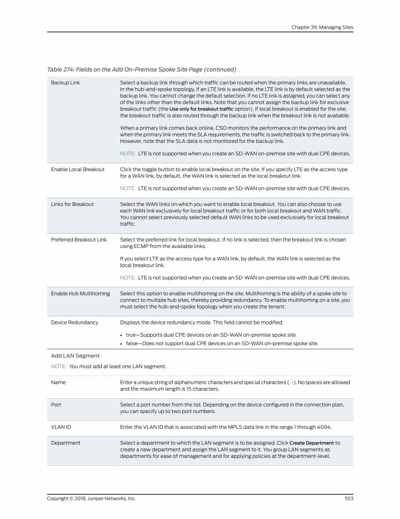
Table 274: Fields on the Add On-Premise Spoke Site Page (continued)
Select a backup link through which traffic can be routed when the primary links are unavailable.In the hub-and-spoke topology, if an LTE link is available, the LTE link is by default selected as thebackup link. You cannot change the default selection. If no LTE link is assigned, you can select anyof the links other than the default links. Note that you cannot assign the backup link for exclusivebreakout traffic (the Use only for breakout traffic option). If local breakout is enabled for the site,the breakout traffic is also routed through the backup link when the breakout link is not available.
When a primary link comes back online, CSOmonitors the performance on the primary link andwhen the primary linkmeets the SLA requirements, the traffic is switched back to the primary link.However, note that the SLA data is not monitored for the backup link.
NOTE: LTE is not supported when you create an SD-WAN on-premise site with dual CPE devices.
Backup Link
Click the toggle button to enable local breakout on the site. If you specify LTE as the access typefor aWAN link, by default, theWAN link is selected as the local breakout link.
NOTE: LTE is not supported when you create an SD-WAN on-premise site with dual CPE devices.
Enable Local Breakout
Select theWAN links on which you want to enable local breakout. You can also choose to useeachWAN link exclusively for local breakout traffic or for both local breakout andWAN traffic.You cannot select previously selected default WAN links to be used exclusively for local breakouttraffic.
Links for Breakout
Select the preferred link for local breakout. If no link is selected, then the breakout link is chosenusing ECMP from the available links.
If you select LTE as the access type for aWAN link, by default, theWAN link is selected as thelocal breakout link.
NOTE: LTE is not supported when you create an SD-WAN on-premise site with dual CPE devices.
Preferred Breakout Link
Select this option to enable multihoming on the site. Multihoming is the ability of a spoke site toconnect tomultiple hub sites, thereby providing redundancy. To enablemultihoming on a site, youmust select the hub-and-spoke topology when you create the tenant.
Enable Hub Multihoming
Displays the device redundancy mode. This field cannot bemodified.
• true—Supports dual CPE devices on an SD-WAN on-premise spoke site
• false—Does not support dual CPE devices on an SD-WAN on-premise spoke site.
Device Redundancy
Add LAN Segment
NOTE: Youmust add at least one LAN segment.
Enter auniquestringofalphanumeric charactersandspecial characters (. -).Nospacesareallowedand themaximum length is 15 characters.
Name
Select a port number from the list. Depending on the device configured in the connection plan,you can specify up to two port numbers.
Port
Enter the VLAN ID that is associated with the MPLS data link in the range 1 through 4094.VLAN ID
Select a department to which the LAN segment is to be assigned. Click Create Department tocreate a new department and assign the LAN segment to it. You group LAN segments asdepartments for ease of management and for applying policies at the department-level.
Department
553Copyright © 2018, Juniper Networks, Inc.
Chapter 39: Managing Sites
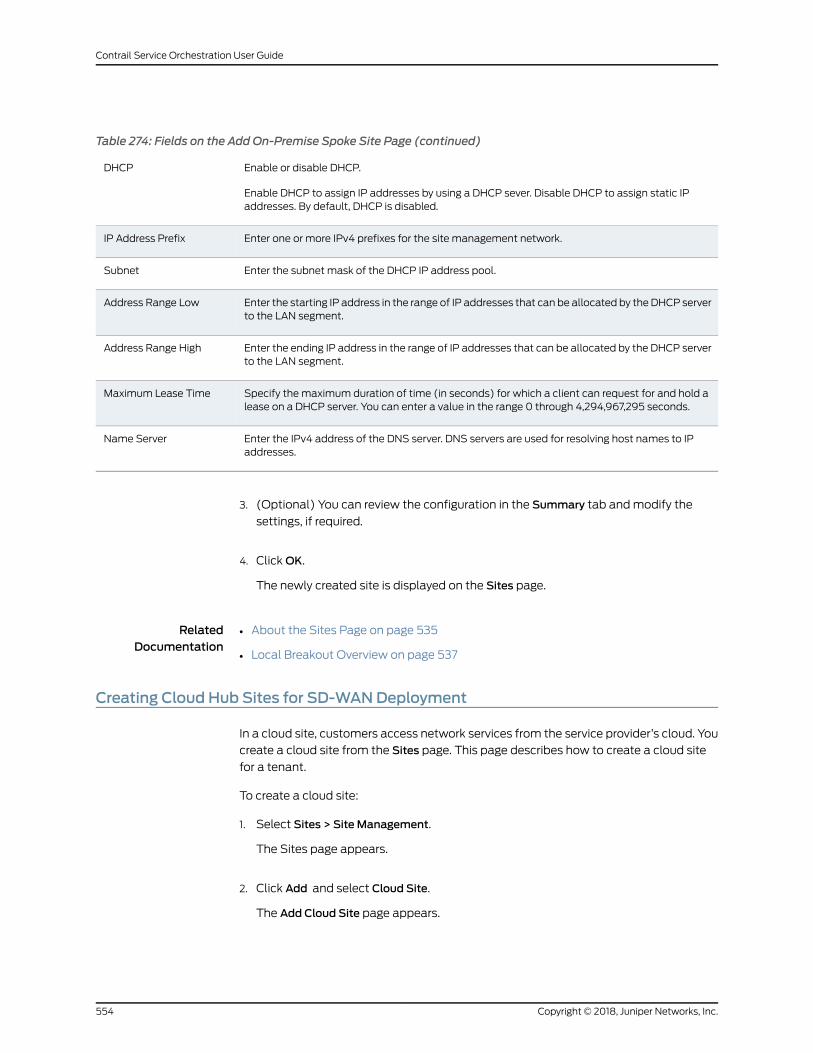
Table 274: Fields on the Add On-Premise Spoke Site Page (continued)
Enable or disable DHCP.
Enable DHCP to assign IP addresses by using a DHCP sever. Disable DHCP to assign static IPaddresses. By default, DHCP is disabled.
DHCP
Enter one or more IPv4 prefixes for the site management network.IP Address Prefix
Enter the subnet mask of the DHCP IP address pool.Subnet
Enter the starting IP address in the range of IP addresses that can be allocated by theDHCP serverto the LAN segment.
Address Range Low
Enter the ending IP address in the range of IP addresses that can be allocated by the DHCP serverto the LAN segment.
Address Range High
Specify the maximum duration of time (in seconds) for which a client can request for and hold alease on a DHCP server. You can enter a value in the range 0 through 4,294,967,295 seconds.
Maximum Lease Time
Enter the IPv4 address of the DNS server. DNS servers are used for resolving host names to IPaddresses.
Name Server
3. (Optional) You can review the configuration in the Summary tab andmodify the
settings, if required.
4. ClickOK.
The newly created site is displayed on the Sites page.
RelatedDocumentation
About the Sites Page on page 535•
• Local Breakout Overview on page 537
Creating Cloud Hub Sites for SD-WANDeployment
In a cloud site, customers access network services from the service provider’s cloud. You
create a cloud site from the Sites page. This page describes how to create a cloud site
for a tenant.
To create a cloud site:
1. Select Sites > Site Management.
The Sites page appears.
2. Click Add and select Cloud Site.
The Add Cloud Site page appears.
Copyright © 2018, Juniper Networks, Inc.554
Contrail Service Orchestration User Guide
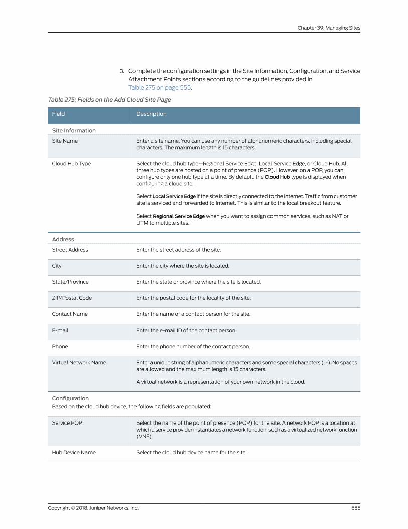
3. Complete the configuration settings in theSite Information, Configuration, andService
Attachment Points sections according to the guidelines provided in
Table 275 on page 555.
Table 275: Fields on the Add Cloud Site Page
DescriptionField
Site Information
Enter a site name. You can use any number of alphanumeric characters, including specialcharacters. Themaximum length is 15 characters.
Site Name
Select the cloud hub type—Regional Service Edge, Local Service Edge, or Cloud Hub. Allthree hub types are hosted on a point of presence (POP). However, on a POP, you canconfigure only one hub type at a time. By default, the Cloud Hub type is displayed whenconfiguring a cloud site.
SelectLocalServiceEdge if the site isdirectly connected to the Internet. Traffic fromcustomersite is serviced and forwarded to Internet. This is similar to the local breakout feature.
Select Regional Service Edgewhen you want to assign common services, such as NAT orUTM tomultiple sites.
Cloud Hub Type
Address
Enter the street address of the site.Street Address
Enter the city where the site is located.City
Enter the state or province where the site is located.State/Province
Enter the postal code for the locality of the site.ZIP/Postal Code
Enter the name of a contact person for the site.Contact Name
Enter the e-mail ID of the contact person.E-mail
Enter the phone number of the contact person.Phone
Enter auniquestringofalphanumeric charactersandsomespecial characters (. -).Nospacesare allowed and themaximum length is 15 characters.
A virtual network is a representation of your own network in the cloud.
Virtual Network Name
Configuration
Based on the cloud hub device, the following fields are populated:
Select the name of the point of presence (POP) for the site. A network POP is a location atwhichaserviceprovider instantiatesanetwork function, suchasavirtualizednetwork function(VNF).
Service POP
Select the cloud hub device name for the site.Hub Device Name
555Copyright © 2018, Juniper Networks, Inc.
Chapter 39: Managing Sites
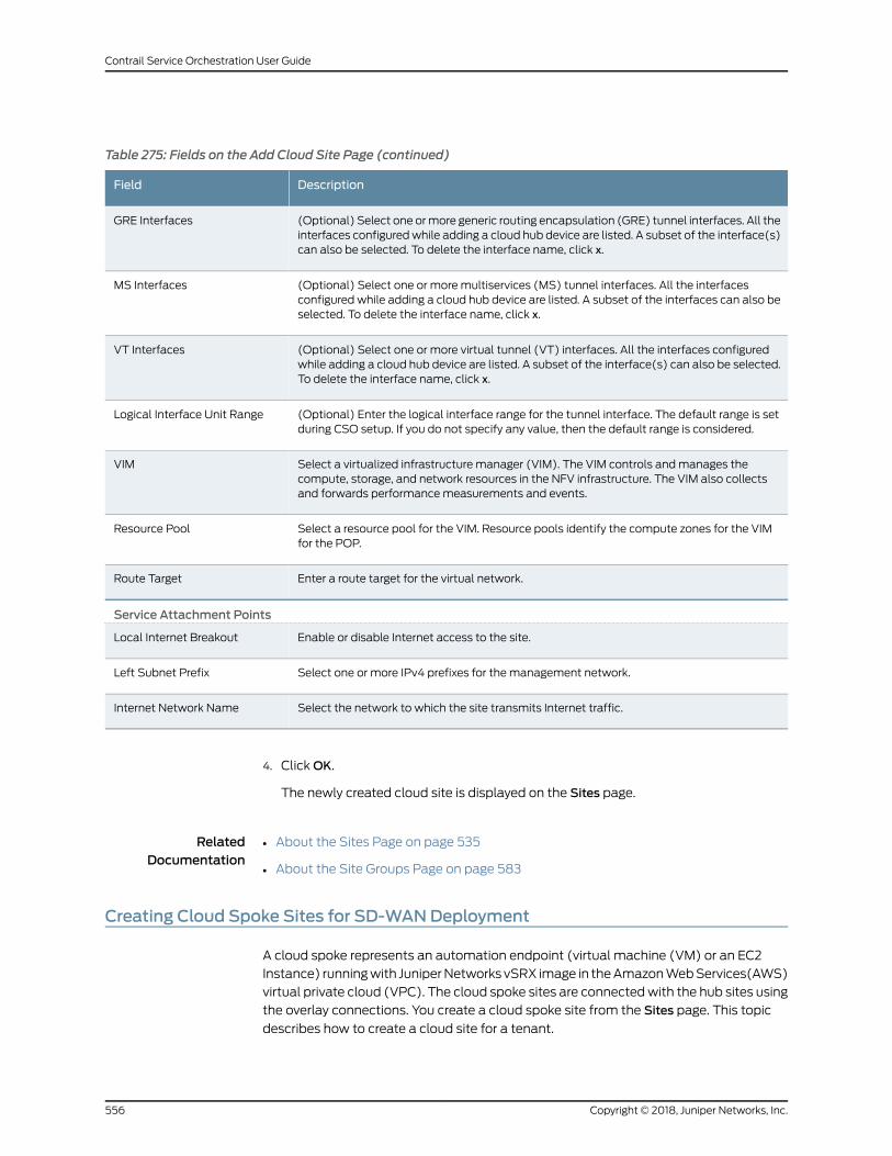
Table 275: Fields on the Add Cloud Site Page (continued)
DescriptionField
(Optional) Select one ormore generic routing encapsulation (GRE) tunnel interfaces. All theinterfaces configuredwhile adding a cloud hub device are listed. A subset of the interface(s)can also be selected. To delete the interface name, click x.
GRE Interfaces
(Optional) Select one or more multiservices (MS) tunnel interfaces. All the interfacesconfigured while adding a cloud hub device are listed. A subset of the interfaces can also beselected. To delete the interface name, click x.
MS Interfaces
(Optional) Select one or more virtual tunnel (VT) interfaces. All the interfaces configuredwhile adding a cloud hub device are listed. A subset of the interface(s) can also be selected.To delete the interface name, click x.
VT Interfaces
(Optional) Enter the logical interface range for the tunnel interface. The default range is setduring CSO setup. If you do not specify any value, then the default range is considered.
Logical Interface Unit Range
Select a virtualized infrastructure manager (VIM). The VIM controls andmanages thecompute, storage, and network resources in the NFV infrastructure. The VIM also collectsand forwards performancemeasurements and events.
VIM
Select a resource pool for the VIM. Resource pools identify the compute zones for the VIMfor the POP.
Resource Pool
Enter a route target for the virtual network.Route Target
Service Attachment Points
Enable or disable Internet access to the site.Local Internet Breakout
Select one or more IPv4 prefixes for the management network.Left Subnet Prefix
Select the network to which the site transmits Internet traffic.Internet Network Name
4. ClickOK.
The newly created cloud site is displayed on the Sites page.
RelatedDocumentation
About the Sites Page on page 535•
• About the Site Groups Page on page 583
Creating Cloud Spoke Sites for SD-WANDeployment
A cloud spoke represents an automation endpoint (virtual machine (VM) or an EC2
Instance) runningwith JuniperNetworks vSRX image in theAmazonWebServices(AWS)
virtual private cloud (VPC). The cloud spoke sites are connectedwith the hub sites using
the overlay connections. You create a cloud spoke site from the Sites page. This topic
describes how to create a cloud site for a tenant.
Copyright © 2018, Juniper Networks, Inc.556
Contrail Service Orchestration User Guide
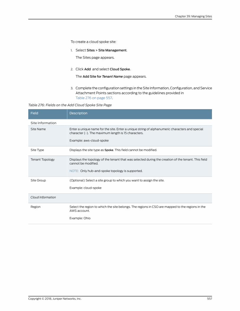
To create a cloud spoke site:
1. Select Sites > Site Management.
The Sites page appears.
2. Click Add and select Cloud Spoke.
The Add Site for Tenant Name page appears.
3. Complete the configuration settings in theSite Information, Configuration, andService
Attachment Points sections according to the guidelines provided in
Table 276 on page 557.
Table 276: Fields on the Add Cloud Spoke Site Page
DescriptionField
Site Information
Enter a unique name for the site. Enter a unique string of alphanumeric characters and specialcharacter (-). Themaximum length is 15 characters.
Example: aws-cloud-spoke
Site Name
Displays the site type as Spoke. This field cannot bemodified.Site Type
Displays the topology of the tenant that was selected during the creation of the tenant. This fieldcannot bemodified.
NOTE: Only hub-and-spoke topology is supported.
Tenant Topology
(Optional) Select a site group to which you want to assign the site.
Example: cloud-spoke
Site Group
Cloud Information
Select the region to which the site belongs. The regions in CSO are mapped to the regions in theAWS account.
Example: Ohio
Region
557Copyright © 2018, Juniper Networks, Inc.
Chapter 39: Managing Sites
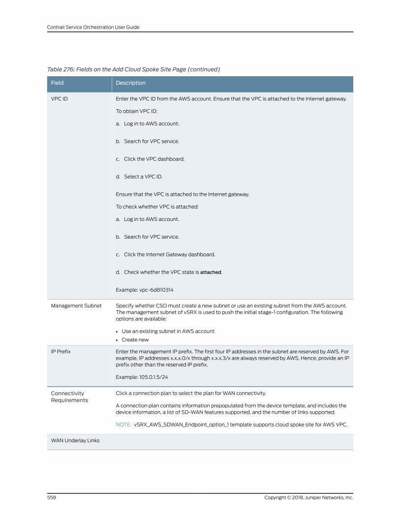
Table 276: Fields on the Add Cloud Spoke Site Page (continued)
DescriptionField
Enter the VPC ID from the AWS account. Ensure that the VPC is attached to the Internet gateway.
To obtain VPC ID:
a. Log in to AWS account.
b. Search for VPC service.
c. Click the VPC dashboard.
d. Select a VPC ID.
Ensure that the VPC is attached to the Internet gateway.
To check whether VPC is attached:
a. Log in to AWS account.
b. Search for VPC service.
c. Click the Internet Gateway dashboard.
d. Check whether the VPC state is attached.
Example: vpc-6d810314
VPC ID
Specify whether CSOmust create a new subnet or use an existing subnet from the AWS account.Themanagement subnet of vSRX is used to push the initial stage-1 configuration. The followingoptions are available:
• Use an existing subnet in AWS account
• Create new
Management Subnet
Enter the management IP prefix. The first four IP addresses in the subnet are reserved by AWS. Forexample, IP addresses x.x.x.0/x through x.x.x.3/x are always reserved by AWS. Hence, provide an IPprefix other than the reserved IP prefix.
Example: 105.0.1.5/24
IP Prefix
Click a connection plan to select the plan for WAN connectivity.
A connection plan contains information prepopulated from the device template, and includes thedevice information, a list of SD-WAN features supported, and the number of links supported.
NOTE: vSRX_AWS_SDWAN_Endpoint_option_1 template supports cloud spoke site for AWS VPC.
ConnectivityRequirements
WANUnderlay Links
Copyright © 2018, Juniper Networks, Inc.558
Contrail Service Orchestration User Guide
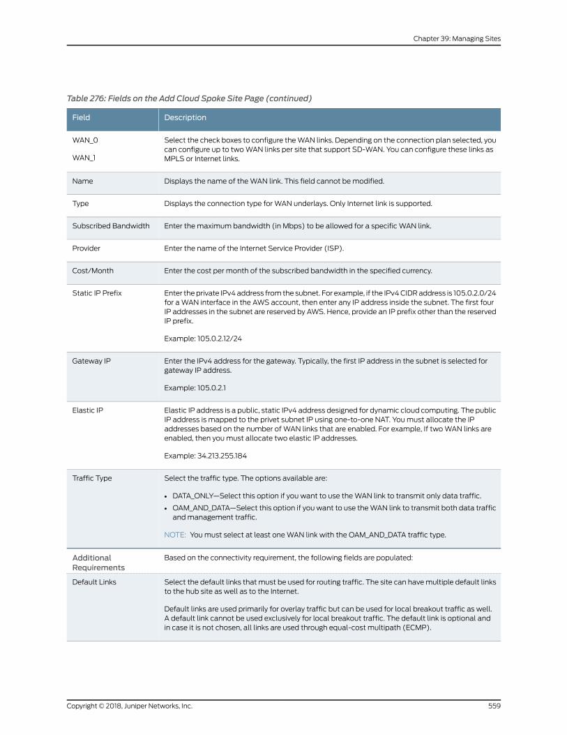
Table 276: Fields on the Add Cloud Spoke Site Page (continued)
DescriptionField
Select the check boxes to configure theWAN links. Depending on the connection plan selected, youcan configure up to twoWAN links per site that support SD-WAN. You can configure these links asMPLS or Internet links.
WAN_0
WAN_1
Displays the name of theWAN link. This field cannot bemodified.Name
Displays the connection type for WAN underlays. Only Internet link is supported.Type
Enter the maximum bandwidth (in Mbps) to be allowed for a specific WAN link.Subscribed Bandwidth
Enter the name of the Internet Service Provider (ISP).Provider
Enter the cost per month of the subscribed bandwidth in the specified currency.Cost/Month
Enter theprivate IPv4address fromthe subnet. For example, if the IPv4CIDRaddress is 105.0.2.0/24for aWAN interface in the AWS account, then enter any IP address inside the subnet. The first fourIP addresses in the subnet are reserved by AWS. Hence, provide an IP prefix other than the reservedIP prefix.
Example: 105.0.2.12/24
Static IP Prefix
Enter the IPv4 address for the gateway. Typically, the first IP address in the subnet is selected forgateway IP address.
Example: 105.0.2.1
Gateway IP
Elastic IP address is a public, static IPv4 address designed for dynamic cloud computing. The publicIP address is mapped to the privet subnet IP using one-to-one NAT. Youmust allocate the IPaddresses based on the number of WAN links that are enabled. For example, If twoWAN links areenabled, then youmust allocate two elastic IP addresses.
Example: 34.213.255.184
Elastic IP
Select the traffic type. The options available are:
• DATA_ONLY—Select this option if you want to use theWAN link to transmit only data traffic.
• OAM_AND_DATA—Select this option if youwant to use theWAN link to transmit both data trafficandmanagement traffic.
NOTE: Youmust select at least oneWAN link with the OAM_AND_DATA traffic type.
Traffic Type
Based on the connectivity requirement, the following fields are populated:AdditionalRequirements
Select the default links thatmust be used for routing traffic. The site can havemultiple default linksto the hub site as well as to the Internet.
Default links are used primarily for overlay traffic but can be used for local breakout traffic as well.A default link cannot be used exclusively for local breakout traffic. The default link is optional andin case it is not chosen, all links are used through equal-cost multipath (ECMP).
Default Links
559Copyright © 2018, Juniper Networks, Inc.
Chapter 39: Managing Sites
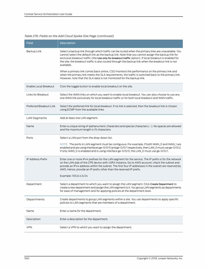
Table 276: Fields on the Add Cloud Spoke Site Page (continued)
DescriptionField
Select a backup link throughwhich traffic can be routedwhen the primary links are unavailable. Youcannot select the default link as the backup link. Note that you cannot assign the backup link forexclusive breakout traffic (the Use only for breakout traffic option). If local breakout is enabled forthe site, the breakout traffic is also routed through the backup link when the breakout link is notavailable.
When a primary link comes back online, CSOmonitors the performance on the primary link andwhen the primary link meets the SLA requirements, the traffic is switched back to the primary link.However, note that the SLA data is not monitored for the backup link.
Backup Link
Click the toggle button to enable local breakout on the site.Enable Local Breakout
Select theWAN links on which you want to enable local breakout. You can also choose to use anyoneWAN link exclusively for local breakout traffic or for both local breakout andWAN traffic.
Links for Breakout
Select the preferred link for local breakout. If no link is selected, then the breakout link is chosenusing ECMP from the available links.
Preferred Breakout Link
Add at least one LAN segment.LAN Segments
Enter a unique string of alphanumeric characters and special characters ( -). No spaces are allowedand themaximum length is 15 characters.
Name
Select a LAN port from the drop-down list.
NOTE: The ports in LAN segmentmust be contiguous. For example, If bothWAN_0 andWAN_1 areenabledandareusing interfacesge-0/0/0andge-0/0/1 respectively, thenLAN_0mustusege-0/0/2.If only WAN_0 is enabled and is using interface ge-0/0/0, the LAN_0must use ge-0/0/1.
Ports
Enter one or more IPv4 prefixes for the LAN segment for the service. The IP prefix is for the networkon the LAN side of the CPE device with vSRX instance. Go to AWS account, check the subnet andprovide an IPv4 address within the subnet. The first four IP addresses in the subnet are reserved byAWS. Hence, provide an IP prefix other than the reserved IP prefix.
Example: 105.0.4.5/24
IP Address Prefix
Select a department to which you want to assign the LAN segment. Click Create Department tocreateanewdepartmentandassign theLANsegment to it. YougroupLANsegmentsasdepartmentsfor ease of management and for applying policies at the department level.
Department
Create departments to group LAN segments within a site. You use departments to apply specificpolicies to LAN segments that are members of a department.
Departments
Enter a name for the department.Name
Enter a description for the department.Description
Select a VPN to which you want to assign the department.VPN
Copyright © 2018, Juniper Networks, Inc.560
Contrail Service Orchestration User Guide
4. Review the configuration andmodify the settings, if needed, from the Summary tab.
5. ClickOK.
The newly created cloud site is displayed on the Sites page.
RelatedDocumentation
Provisioning a Cloud Spoke Site in AWS VPC on page 561•
• About the Sites Page on page 535
• About the Site Groups Page on page 583
Provisioning a Cloud Spoke Site in AWSVPC
Use the following high-level steps to provision a vSRX cloud spoke site in AmazonWeb
Services (AWS) virtual private cloud (VPC).
Before you begin:
• Set up your AmazonWeb Services (AWS) account.
• Identify the virtual private cloud (VPC) to which the AWS spoke site must be
provisioned.
• Install licenses to use vSRX features. Choose any of the following AWS vSRX Image
Licenses.
• Bring Your Own License (BYOL)— If you plan to use a BYOL, then youmust install
the license to the device before deploying CSO SD-WAN functionality. See
https://aws.amazon.com/marketplace/pp/B01LYWCGDX.
• License included. See https://aws.amazon.com/marketplace/pp/B01NAUWN0G.
• Ensure that you have the supported software version for the AWS spoke.
To set up andmonitor your network:
• Add a Cloud Spoke Site on page 561
• Configure the Cloud Spoke Site on page 562
• Download the Cloud Formation Template on page 563
• Provision the Device on AWS Server on page 563
• Activate the Device on page 564
Add a Cloud Spoke Site
To add a cloud spoke site:
1. Select Sites > Site Management > Add > Cloud Spoke.
2. Specify the site information such as, site name, AWS region, VPC ID, management
subnet, IP prefix and click Next.
561Copyright © 2018, Juniper Networks, Inc.
Chapter 39: Managing Sites
3. Specify vSRX_AWS_SDWAN_Endpoint_option_1 as the connection plan.
NOTE:• Only Hub-Spoke topology is supported for AWS cloud spoke site.
• Only Internet link is supported forWAN underlay connections.
4. Provide theWAN details and click Next.
TheWANtrafficpageappears, displayingasetof values for theWAN linkconfiguration.
5. Specify additional requirements and click Next.
6. Specify LAN segment information and click Next.
7. In the Summary tab, check the configuration and click Edit to modify the settings.
8. ClickOK to save the changes.
The new cloud spoke site that you created appears in the Sites page.
Configure the Cloud Spoke Site
To configure a cloud spoke site:
1. Select Sites > Site Management .
The sites page appears.
2. Select the cloud spoke site that you created and click Configure Site.
The configure site page appears.
3. In theConnectivity tab, specify the primary hub site detail, overlay tunnel information,
andWAN interface details.
4. ClickOk.
5. Click Devices tab and enter the activation code provided by your service provider.
6. ClickOk
The site status is changed to Configured.
Copyright © 2018, Juniper Networks, Inc.562
Contrail Service Orchestration User Guide
Download the Cloud Formation Template
To download the cloud formation template:
1. Click Resources > Devices.
2. Identify the device that you want to activate.
You can activate a device if it has the status as Expected.
3. Select the device and click Activate Device.
The Activate device page appears.
4. Enter the activation code supplied by the service provider.
You candownload the cloud formation template after you enter the correct activation
code.
5. Click Download to download the cloud formation template.
The template is downloaded to your local computer in JSON format.
Provision the Device on AWSServer
CSOcreatescloud formation templatewith stage-1 configurationbundled in JSONformat.
Youmust download this template and then upload to AWS to provision the vSRX. The
cloud formation template creates the required resources such as subnet, interface, vSRX
and so on and applies the stage-1 configuration.
To provision the device on AWS server:
1. Log in to your AWS account.
• If you have already logged in to your AWS account, the Create Stack page appears.
• If youare not logged into yourAWSaccount, a newWebpageopens in your browser,
displaying the AWS login information. Log in to your AWS account.
TIP: If youdonot see theCreateStackpagewhenyou log in toor accessyour AWS account, then search for CloudFormation service.
The Create Stack page appears.
2. Select CloudFormation > Stacks > Create Stack > Upload a template to Amazon S3.
3. Click Choose File and select the cloud formation template that you downloaded in
JSON format .
4. Click Next.
563Copyright © 2018, Juniper Networks, Inc.
Chapter 39: Managing Sites
5. Specify the Stack name. For example, Oregonstack.
6. Specify the Custom Image Id for the vSRX.
Youmust ensure that you have the supported software image for the AWS spoke. If
the image is unavailable on the AWSmarketplace, youmust do the following to get
the AMI number for your desired region:
a. Search the public AMI for media-srxmr-vmdisk-Version-Number, where
Version-Number is the vSRX software image supported on AWS, and note down
the AMI ID (for your region) that corresponds to this image.
For example, if the supported software version is 15.1X49.D133, then search the
public AMI for media-srxmr-vmdisk-15.1X49-D133 and note down the AMI ID.
b. Paste the AMI ID in the CustomImageId field.
NOTE: Youmust specify the Custom Image ID field because not doing soresults in failure during stack creation or provisioning.
7. In the Parameters section, specify the KeyName for your EC2 instance.
8. Click Next.
9. Select I acknowledge that AWSCloudFormationmight create IAMResources.
10. Click Create.
TheCreateStackpagesdisplaysa list of existing stacksand indicates that it is creating
the stack that you requested. The create stack process takes up to 30minutes. if the
process does not complete in 30minutes, a timeout occurs and you need to retry the
process.
Activate the Device
To activate the device:.
1. After the create stack process is complete, return to the Customer Portal and click
Next.
The Activate Device page displays a status indicating that CSO is detecting the
provisioning agent. This process takes up to 30minutes. if the process does not
complete in 30minutes, a timeout occurs and you need to retry the process.
Copyright © 2018, Juniper Networks, Inc.564
Contrail Service Orchestration User Guide
NOTE: You need not download the cloud formation template again. Youcan log in to the Customer Portal, access the Activate Device page, entertheactivationcodeandclickNext. After theCREATE_COMPLETEmessage
is displayed on the AWS server, click Next on the Activate Device page toproceed with device activation.
If the spoke on AWS has been spawned successfully on AWS, it will contact CSO
through outbound SSH connection. The device is detected and normal ZTP, process
is triggered. The rest of the workflow is consistent with the normal on-premise
workflow.
On Device Activation page, the device is activated through the following steps:
• Detecting the device
• Applying stage-one configuration to the device
• Bootstrapping of device
• Activating the device
After each successful step, you can see a green checkmark. If any of these steps fails,
a red exclamation mark appears.
2. After the activation process is complete, clickOK.
The Sites page appears. To see the device activation status, hover over the device
icon on the Sites page.
RelatedDocumentation
Creating Cloud Spoke Sites for SD-WAN Deployment on page 556•
ImportingMultiple Sites
Youcanuse the ImportSitespage toconfigurea sitebyuploadinga JSONfile. Toconfigure
a site by using the site upload feature, specify the site parameters in a JavaScript Object
Notation (JSON) file. You can also use the site upload feature to edit the configuration
information of a site. This method enables you to modify only the required parameters
without going through the site creation workflow.
TIP: You can download a sample JSON file from the Download Sample JSON
link and edit the parameters based on the requirements of the site that youwant to configure.
565Copyright © 2018, Juniper Networks, Inc.
Chapter 39: Managing Sites
To configure a site by uploading a JSON file:
1. Click Sites > Add > Import Sites.
The Import Sites page is displayed.
2. Click Browse and navigate to the directory that contains the JSON file.
Alternatively, download a sample JSON file by clicking the Download Sample JSON
link and edit the parameters according to the requirements of the site.
3. Select the file and clickOpen.
4. Click Import.
A success message is displayed indicating that the file is uploaded successfully.
RelatedDocumentation
About the Sites Page on page 535•
Managing a Single Site
You can use the Site Management page to view the site details and to manage the site
configurations for a single site. To access the page, click Sites > Site Management >
Site-Name.
You can perform the following tasks from this page:
• On theOverview tab, view detailed information about the tenant site, such as
geographical location, connection details, device details, alarms, and alerts.
• On theWAN tab, view detailed information about theWAN links, such as topology of
the hub-siteWAN links, total number of hub and spoke links, total number of
applications, linkutilizationdetails, linkmetricsbasedonthroughput, and themaximum
bandwidth capacity of aWAN link in a site.Hover over theWAN link to viewbandwidth
capacity.
For sites owned by a tenant in a full mesh topology, you can view all theWAN link
connections betweenWAN interfaces in all the sites. Click a site to seeall connections
between its WAN interfaces. Because the full mesh topology supports only static
SD-WAN policies, SLA parameters such as throughput, latency, packet loss, delay,
and jitter are not computed.
• OntheServices tab, viewservices, deploynetwork services, start a service, anddisable
services for a tenant site. You can also view the topology of the site.
Todeployanetwork service toa site, select the service, and then select anattachment
point in the topology graphic. Alternatively, drag and drop the network service to an
attachment point in the topology graphic.
Copyright © 2018, Juniper Networks, Inc.566
Contrail Service Orchestration User Guide
• On the Policies tab, view the following details:
• List of all policies applicable to a tenant site. Click the policy name to view the rules
that are applicable for the tenant site. Click the edit icon at the end of the row to
edit a policy. You are taken to the Configuration > Policy page, where you can edit
the policies.
• Details about the tenant user who last updated the policy.
• Time when the policy was last updated.
• Deployment status of the policy—deployed or not deployed.
• Number of rules applicable to the site compared to the total number of rules
applicable to the tenant.
• On the LAN tab, view, create, deploy, and delete a LAN segment. In addition, you can
use this tab to reassign a LANsegment to adifferent department. See “Managing LAN
Segments on a Tenant Site” on page 570.
• On the Devices tab, view a list of devices in your network. See “About the Devices
Page” on page 308.
RelatedDocumentation
About the Sites Page on page 535•
Configuring a Single Site
You can specify the underlay configuration of a hub device by using the Configure Site
feature on the Site Management page.
You can also configure an SD-WAN on-premise spoke site using dual CPE devices. The
workflow to configure a site with dual CPE devices is similar to single CPE device. You
need at least oneWAN link per CPE to act as a OAM_AND_DATA for redundancy, so that
the individual nodes establish connectivity with CSO.
Youmust provide the serial number and the activation code for both the primary and the
secondary devices.
To configure a site:
1. Click the Configure Site button on the Sites > Site Management page.
The Configure Site Site Name page is displayed.
2. Complete the configuration settings according to the guidelines provided in
Table 277 on page 567.
Table 277: Fields on the Configure Site Page
DescriptionField
Displays the site type.Site Type
567Copyright © 2018, Juniper Networks, Inc.
Chapter 39: Managing Sites
Table 277: Fields on the Configure Site Page (continued)
DescriptionField
Displays the regional serverwithwhich the CPE device communicates based on the informationin the device profile. This field cannot bemodified.
Management Region
Displays the connection plan that you selected when you created the site. This field cannot bemodified.
Selected Plan
Displays whether multihoming was enabled or disabled on the site during the creation of thesite. This field cannot bemodified.
Hub Multihoming
Configuration
Connectivity
Management Connectivity
Enable Operation, Administration, and Maintenance (OAM) traffic information to specify theOAMVLAN ID, IP prefix for the sitemanagement network, and gateway IP address of the defaultroute.
OAM Traffic Information
Specify the OAM VLAN ID for in-bandmanagement of the site.VLAN ID
Specify one or more prefixes for the site management network. You can specify IPv4 or IPv6addresses.
Example: 10.0.2.16/24
IP Prefix
Specify the IP address of the default route for the management network. You can use an IPv4or IPv6 address.
Gateway IP
WAN_0, WAN_1, WAN_2, WAN_3
Displays the interface name configured in the device profile. This field cannot bemodified.WAN Interface
Displays the link type (MPLS or Internet) configured in the device profile. This field cannot bemodified.
Link Type
Select the method of IP address assignment. Select DHCP to assign IP addresses by using aDHCP sever or Static to assign a static IP address.
Address Assignment
Select the traffic type. You specify whether you want to use theWAN link to transmit only datatraffic or both management traffic and data traffic.
Youmust select the traffic type asOAM_and_DATAwhen you configure a site with dual CPEdevices. You need at least oneWAN link per CPE to act as a OAM_AND_DATA for redundancy.
Traffic Type
VLAN ID associated with theWAN link.Data VLAN ID
Copyright © 2018, Juniper Networks, Inc.568
Contrail Service Orchestration User Guide
Table 277: Fields on the Configure Site Page (continued)
DescriptionField
Displays whether local breakout was enabled on theWAN link during creation of the site. Thisfield cannot bemodified.
If theWAN link is selected to be used for only local breakout traffic, then theOverlay Tunnelsection is not displayed.
Local Breakout
Select this option to enable interface-based source NAT on theWAN link.
NOTE: If this option is enabled for aWAN interfaceW1during the site creationworkflow, a seriesof NAT source rules are automatically created. Each automatically created NAT rule is from azone to theWAN interface, with a translation of type interface. Each pair of [zone - interface]represents a rule-set.
For example, the following zone toW1 interface rule-set might be created:
Zone1 -->W1: Translation=Interface
Zone2 -->W1: Translation=Interface
Zone3 -->W1: Translation=Interface
Tomanually override any of these rules, you can create a NAT rule within a particular rule-set.For example, to use a source NAT pool instead of an interface for translation, create a NAT rulewithin this particular rule-set, that includes the relevant zone andWAN interface as the sourceand destination. For example:
Zone1 -->W1 : Translation=Pool-2
Themanually createdNAT rule is placedatahigher priority than thecorrespondingautomaticallycreated NAT rule.
You can also add other fields (such as addresses, ports, protocols, and so on) as part of thesource or destination endpoints. For example:
Zone1, Port 56578 -->W1: Translation=Pool-2
AutocreateSourceNATRule
Overlay Tunnel
Select the tunnel type—GRE or GRE over IPsec.Tunnel Type
Displays the hub device to which the site is connected.Peer Device
Select thenameof the interfaceof thehubdevice towhich theMPLSor Internet link is connected.Interface Name
Devices
Assign CPE Devices
Displays whether device redundancy is enabled or disabled for an SD-WAN on-premise spokesite.
Device Redundancy
Enter the serial number of the primary CPE device. You can use a unique string of alphanumericcharacters. Themaximum length is 64 characters. Serial numbers are case-sensitive.
Primary Device SerialNumber
569Copyright © 2018, Juniper Networks, Inc.
Chapter 39: Managing Sites
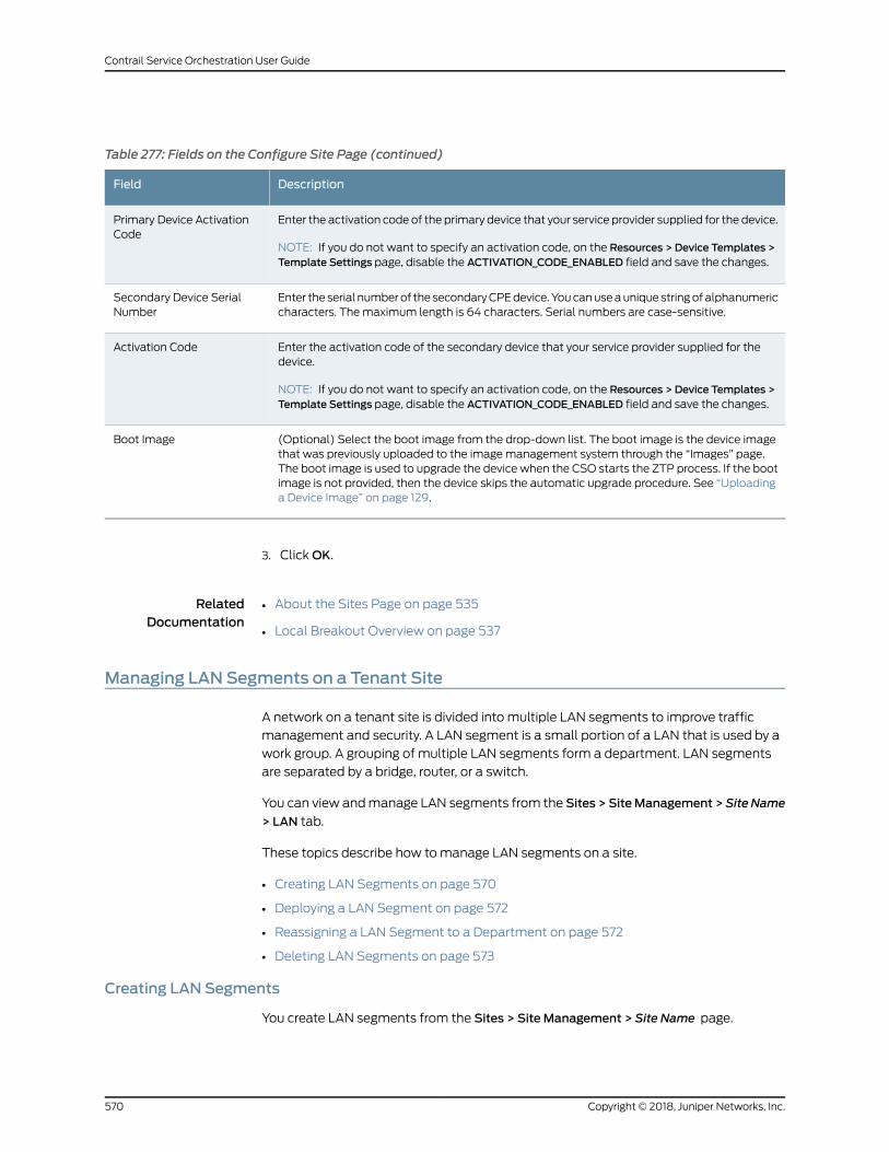
Table 277: Fields on the Configure Site Page (continued)
DescriptionField
Enter the activation code of the primary device that your service provider supplied for the device.
NOTE: If you do not want to specify an activation code, on the Resources > Device Templates >Template Settings page, disable the ACTIVATION_CODE_ENABLED field and save the changes.
Primary Device ActivationCode
Enter the serial numberof the secondaryCPEdevice.Youcanuseauniquestringofalphanumericcharacters. Themaximum length is 64 characters. Serial numbers are case-sensitive.
Secondary Device SerialNumber
Enter the activation code of the secondary device that your service provider supplied for thedevice.
NOTE: If you do not want to specify an activation code, on the Resources > Device Templates >Template Settings page, disable the ACTIVATION_CODE_ENABLED field and save the changes.
Activation Code
(Optional) Select the boot image from the drop-down list. The boot image is the device imagethat was previously uploaded to the imagemanagement system through the “Images” page.The boot image is used to upgrade the device when the CSO starts the ZTP process. If the bootimage is not provided, then the device skips the automatic upgrade procedure. See “Uploadinga Device Image” on page 129.
Boot Image
3. ClickOK.
RelatedDocumentation
About the Sites Page on page 535•
• Local Breakout Overview on page 537
Managing LAN Segments on a Tenant Site
A network on a tenant site is divided into multiple LAN segments to improve traffic
management and security. A LAN segment is a small portion of a LAN that is used by a
work group. A grouping of multiple LAN segments form a department. LAN segments
are separated by a bridge, router, or a switch.
You can view andmanage LAN segments from the Sites > SiteManagement >Site Name
> LAN tab.
These topics describe how tomanage LAN segments on a site.
• Creating LAN Segments on page 570
• Deploying a LAN Segment on page 572
• Reassigning a LAN Segment to a Department on page 572
• Deleting LAN Segments on page 573
Creating LAN Segments
You create LAN segments from the Sites > Site Management > Site Name page.
Copyright © 2018, Juniper Networks, Inc.570
Contrail Service Orchestration User Guide
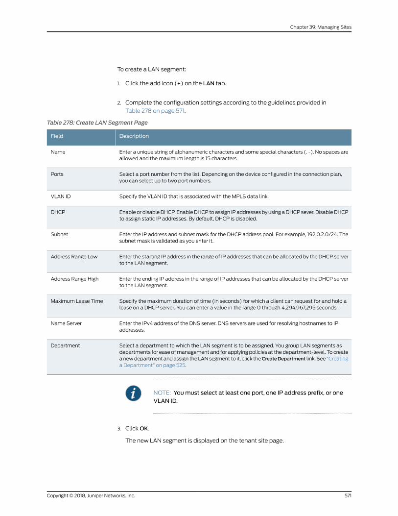
To create a LAN segment:
1. Click the add icon (+) on the LAN tab.
2. Complete the configuration settings according to the guidelines provided in
Table 278 on page 571.
Table 278: Create LAN Segment Page
DescriptionField
Enter a unique string of alphanumeric characters and some special characters (. -). No spaces areallowed and themaximum length is 15 characters.
Name
Select a port number from the list. Depending on the device configured in the connection plan,you can select up to two port numbers.
Ports
Specify the VLAN ID that is associated with the MPLS data link.VLAN ID
Enable or disableDHCP. EnableDHCP toassign IPaddressesbyusing aDHCPsever. DisableDHCPto assign static IP addresses. By default, DHCP is disabled.
DHCP
Enter the IP address and subnet mask for the DHCP address pool. For example, 192.0.2.0/24. Thesubnet mask is validated as you enter it.
Subnet
Enter the starting IP address in the range of IP addresses that can be allocated by the DHCP serverto the LAN segment.
Address Range Low
Enter the ending IP address in the range of IP addresses that can be allocated by the DHCP serverto the LAN segment.
Address Range High
Specify the maximum duration of time (in seconds) for which a client can request for and hold alease on a DHCP server. You can enter a value in the range 0 through 4,294,967,295 seconds.
Maximum Lease Time
Enter the IPv4 address of the DNS server. DNS servers are used for resolving hostnames to IPaddresses.
Name Server
Select a department to which the LAN segment is to be assigned. You group LAN segments asdepartments for ease ofmanagement and for applying policies at the department-level. To createanewdepartmentandassign theLANsegment to it, click theCreateDepartment link. See “Creatinga Department” on page 525.
Department
NOTE: Youmust select at least one port, one IP address prefix, or oneVLAN ID.
3. ClickOK.
The new LAN segment is displayed on the tenant site page.
571Copyright © 2018, Juniper Networks, Inc.
Chapter 39: Managing Sites
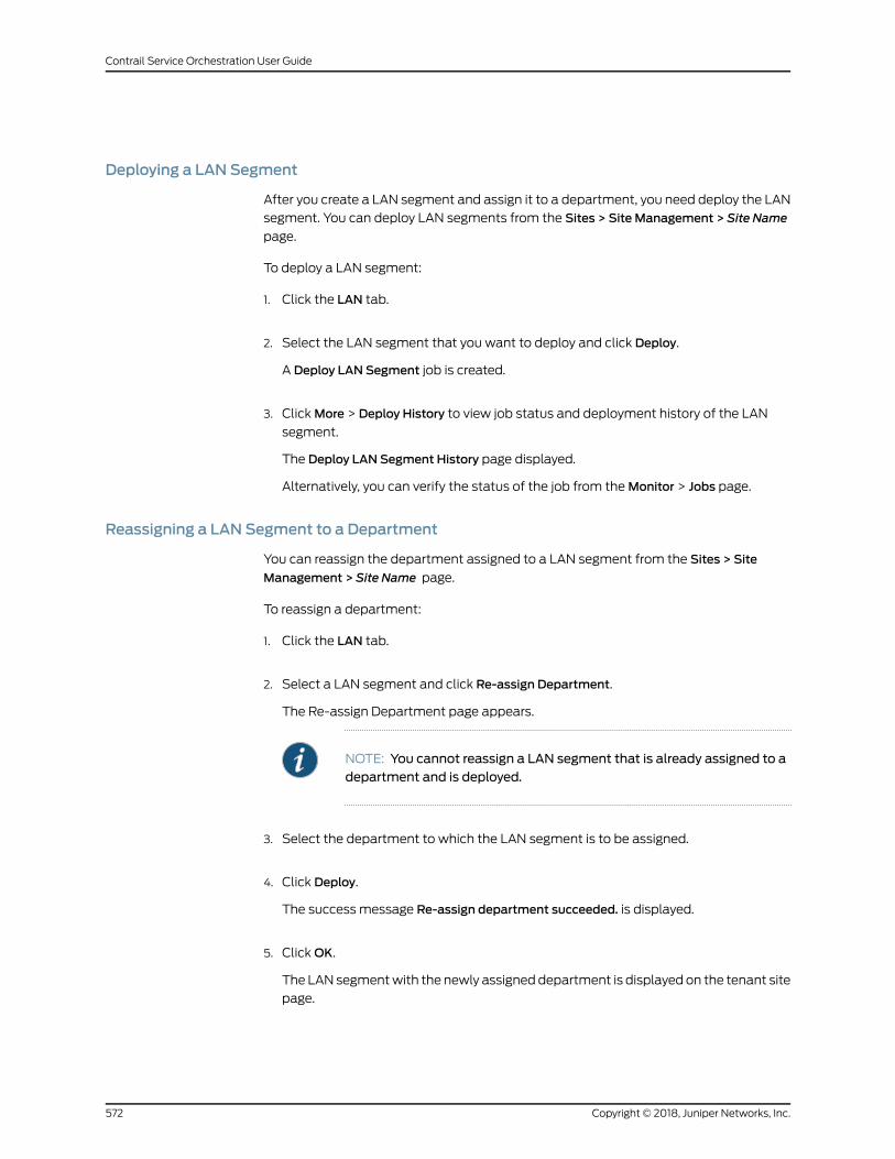
Deploying a LAN Segment
After you create a LAN segment and assign it to a department, you need deploy the LAN
segment. You can deploy LAN segments from the Sites > Site Management > Site Name
page.
To deploy a LAN segment:
1. Click the LAN tab.
2. Select the LAN segment that you want to deploy and click Deploy.
A Deploy LAN Segment job is created.
3. ClickMore > Deploy History to view job status and deployment history of the LAN
segment.
The Deploy LAN Segment History page displayed.
Alternatively, you can verify the status of the job from theMonitor > Jobs page.
Reassigning a LAN Segment to a Department
You can reassign the department assigned to a LAN segment from the Sites > Site
Management > Site Name page.
To reassign a department:
1. Click the LAN tab.
2. Select a LAN segment and click Re-assign Department.
The Re-assign Department page appears.
NOTE: You cannot reassign a LAN segment that is already assigned to adepartment and is deployed.
3. Select the department to which the LAN segment is to be assigned.
4. Click Deploy.
The success message Re-assign department succeeded. is displayed.
5. ClickOK.
The LAN segmentwith the newly assigned department is displayed on the tenant site
page.
Copyright © 2018, Juniper Networks, Inc.572
Contrail Service Orchestration User Guide
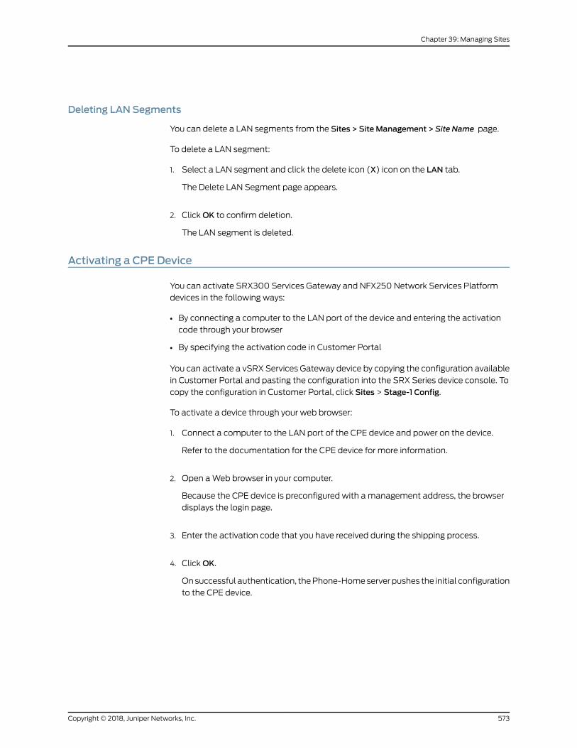
Deleting LAN Segments
You can delete a LAN segments from the Sites > Site Management > Site Name page.
To delete a LAN segment:
1. Select a LAN segment and click the delete icon (X) icon on the LAN tab.
The Delete LAN Segment page appears.
2. ClickOK to confirm deletion.
The LAN segment is deleted.
Activating a CPE Device
You can activate SRX300 Services Gateway and NFX250 Network Services Platform
devices in the following ways:
• By connecting a computer to the LAN port of the device and entering the activation
code through your browser
• By specifying the activation code in Customer Portal
You can activate a vSRX Services Gateway device by copying the configuration available
in Customer Portal and pasting the configuration into the SRX Series device console. To
copy the configuration in Customer Portal, click Sites > Stage-1 Config.
To activate a device through your web browser:
1. Connect a computer to the LAN port of the CPE device and power on the device.
Refer to the documentation for the CPE device for more information.
2. Open aWeb browser in your computer.
Because the CPE device is preconfigured with amanagement address, the browser
displays the login page.
3. Enter the activation code that you have received during the shipping process.
4. ClickOK.
Onsuccessful authentication, thePhone-Homeserverpushes the initial configuration
to the CPE device.
573Copyright © 2018, Juniper Networks, Inc.
Chapter 39: Managing Sites
To activate a device through Customer Portal:
NOTE: If you activate the CPE device through Customer Portal, you do notneed to activate it through a browser.
1. Log in to Customer Portal.
2. Click the Sites page in Customer Portal.
After you use Customer Portal to add a site that uses a CPE device, the CPE device
icon on the Sites page is gray if the device is inactive. When you hover over the CPE
device icon on theMonitor page, you should see themessageDeviceStatus: Expected,
which indicates that the device is ready to be activated. If you see themessageDevice
Status: Undefined, contact your service provider for assistance.
3. On the Device Status column, click Activate Device.
The Activate Device page appears. The Activate Device page consists of Device
Information and Device Activation.
4. OnDevice Information page, view the site details, device details, and recipient details,
and specify the activation code. For more information see, Table 279 on page 575.
5. Click Next.
On Device Activation page, the device is activated through the following steps:
• Detecting the device
• Applying stage-one configuration to the device
• Bootstrapping of device
• Activating the device
After each successful step, you can see a green check mark. If any of these steps fail,
a red exclamation mark appears.
6. After the activation process is complete, clickOK.
The Sites page appears. To see the device activation status, hover over the device
icon on the Sites page. You see one of the following statuses:
• EXPECTED—Device is ready for activation.
• ACTIVE—Device is authenticated but not yet operational.
• ACTIVATION_FAILED—Device is not authenticated.
• GWR_SPAWNED—Device gateway component spawning is successful.
• GWR_SPAWN_FAILED—Device gateway component spawning fails.
Copyright © 2018, Juniper Networks, Inc.574
Contrail Service Orchestration User Guide
• PROVISIONED—Device is operational.
• PROVISION_FAILED—Device failed to become operational. Contact your service
provider for assistance.
NOTE: When a device is provisioned successfully, a job to install thedefault trusted certificates, which are packaged with Junos OS, on thedevice is triggered. You can view the details of the job (of type default
trustedcertificate) on the Jobs page (Monitor > Jobs).
We recommend that you check the job status to verify that the defaulttrusted certificates were successfully installed. If, however, the job failedand if you want to use the SSL proxy feature, manually install the trustedcertificates on the device by using the following procedure:
a. Log in to the device and access the Junos OS CLI (operational mode).
b. Execute the request security pki ca-certificate ca-profile-group load
ca-group-name DEFAULT_CSO filename default command.
The installation takes between 2–5minutes to complete, so wait untilit is done.
c. Exit the Junos OS CLI and log out of the device.
Table 279: Fields on the Activate Device Page
DescriptionField
View the name of the site on which the CPE device is activated.Site Name & Type
View the name of the hub to which the CPE device is connected.Connected Hub
View the device model.Device Model
View the serial number of the CPE device.Serial Number
Specify the activation code that your service provider supplied for the CPE device.Activation Code
Specify how long youmust wait to activate the device after it boots up. You can seta duration in the range 1 through 600 seconds. The default is 120 seconds.
Expiry Duration
View the recipient details.Recipient
RelatedDocumentation
http://www.juniper.net/techpubs/en_US/release-independen
t/junos/information-products/pathway-pages/nfx-series/product/
•
575Copyright © 2018, Juniper Networks, Inc.
Chapter 39: Managing Sites
• About the Sites Page on page 535
• Creating On-Premise Spoke Sites for SD-WAN Deployment on page 549
• Configuring a Single Site on page 567
• About the Certificates Page on page 617
Activating Dual CPE Devices (Device Redundancy)
You can activate a device after the device status is changed to EXPECTED in the Sites
page. When you see the device status is EXPECTED, it indicates that the device is ready
to be activated. If you see the device status as Undefined, contact your service provider
for assistance.
NOTE: Youmust activate both the primary and the secondary devicessimultaneously.
Youmustuse thesamedevicemodel forbothprimaryandsecondarydevicesand the devicesmust have the same version of Junos OS installed.
To activate dual CPE devices used as a cluster:
1. Log in to Customer Portal.
2. Select Sites.
The Sites page appears.
3. Click on the Site Name.
The Site Name page appears.
4. On Devices tab, select the cluster device and click Activate Device.
The Activate Device page appears. The Activate Device page consists of Device
Information and Device Activation tabs.
NOTE: You can also activate the device through Resource > Devices page.
5. On Device Information page, complete the configuration according to the guidelines
provided in Table 280 on page 576.
Table 280: Fields on the Activate Device Page
DescriptionField
View the name of the site on which the CPE device is activated.Site Name & Type
Copyright © 2018, Juniper Networks, Inc.576
Contrail Service Orchestration User Guide
Table 280: Fields on the Activate Device Page (continued)
DescriptionField
View the name of the region to which the CPE device is connected.Connected Region
View the serial number of the primary CPE device.Primary Device Serial Number
Enter the activation code of the primary device that your service provider supplied forthe device.
NOTE: If you do not want to specify an activation code, on the Resources > EditTemplate > Template Settings page, disable the ACTIVATION_CODE_ENABLED fieldand save the changes.
Primary Device Activation Code
View the serial number of the secondary CPE device.Secondary Device Serial Number
Enter the activation code of the secondary device that your service provider suppliedfor the device.
NOTE: If you do not want to specify an activation code, on the Resources > EditTemplate > Template Settings page, disable the ACTIVATION_CODE_ENABLED fieldand save the changes.
Secondary Device Activation Code
6. Click Next.
The Activate Device page appears.
7. OnActivateDevice page, the cluster device (both primary and secondary) is activated
through the following steps:
• Device is detected
• Stage-one configuration apply on device is successful
• Bootstrap of device success
• Activation of device is successful
• Device is modelled and is expected to be activated
• Device is active
• Device gateway component is spawned
• Device gateway router is put into cluster mode.
• Device is successful provisioned
After each successful step, you can see a green check mark. If any of these steps fail,
a red exclamation mark appears.
8. After the activation process is complete, clickOK.
577Copyright © 2018, Juniper Networks, Inc.
Chapter 39: Managing Sites
The Site Name page appears. If the device activation is successful, the management
statusof thecluster device is changed toPROVISIONED. Youcanalso see the following
device states:
• EXPECTED—Device is ready for activation.
• ACTIVE—Device is authenticated but not yet operational.
• ACTIVATION_FAILED—Device is not authenticated.
• GWR_SPAWNED—Device gateway component spawning is successful.
• GWR_SPAWN_FAILED—Device gateway component spawning fails.
• PROVISIONED—Device is operational.
• PROVISION_FAILED—Device failed to become operational. Contact your service
provider for assistance.
NOTE: The GWR_SPAWNED and GWR_SPAWN_FAILED statuses are not
applicable for dual CPE SRX Series Services Gateway devices.
RelatedDocumentation
Device Redundancy Support Overview on page 539•
• Activating a CPE Device on page 573
• About the Sites Page on page 535
• Creating On-Premise Spoke Sites for SD-WAN Deployment on page 549
• Configuring a Single Site on page 567
• About the Certificates Page on page 617
Viewing the History of Tenant Device Activation Logs
You can use the Activation Logs page to view the history of device activation logs. You
can also view the details of the activation logs and their status.
To view the device activation logs:
1. Click Resources > Tenant Devices.
The Tenant Devices page appears, which list all devices.
2. Select a device and clickMore > Activation Logs.
The Activation Logs page is displayed. Table 48 on page 100 describes the fields on
the Activation Logs page.
3. Click a task name.
Copyright © 2018, Juniper Networks, Inc.578
Contrail Service Orchestration User Guide
The ZTP Logs page appears. Table 49 on page 101 describes the fields on the ZTP
Logs page.
4. Click the Task Name.
The Job Status page appears. Table 50 on page 101 describes the fields on the Job
Status page.
5. ClickOK to return to the previous page.
Table 281: Fields on the ZTP History Page
DescriptionField
View the number of activated tasks that are in progress.In progress
View the number of activated tasks that are successful.Success
View the number of activated tasks that have failed.Failure
View the name of the task.
Example:csp.tssm_ztp-Juniper-site-17-NFX-250-8052cc9451914be28c7c98fb64fd0db3
Name
View the start date and time of the task.Start Date
View the end date and time of the task.End Date
View the status of the task to knowwhether the task succeeded or failed.Status
View the import logs. Click a log to access more detailed information aboutthe imported log.
Log
Table 282: Fields on the ZTP Logs Page
DescriptionField
View the ID created for the task.
Example: install-license-to-device
Task Name
View the status of the task to knowwhether the task succeeded or failed.Status
Table 283: Fields on the Job Status Page
DescriptionField
View the name of the task.Name
View the start date and time of the task.Actual Start Time
579Copyright © 2018, Juniper Networks, Inc.
Chapter 39: Managing Sites
Table 283: Fields on the Job Status Page (continued)
DescriptionField
View the name of the user who activated the task.User
View the end date and time of the task.End Time
View the status of the task to knowwhether the task succeeded or failed.State
RelatedDocumentation
About the Tenant Devices Page on page 91•
Configuring VRFs and PNE Details for a Site in a Centralized Deployment
If you use a physical network element (PNE) for a centralized deployment, you can use
the Device Configuration page to configure the virtual routing and forwarding instances
for your customer sites if you have not done so in Contrail and in Junos OS on the MX
Series router.
To configure a VRF and PNE details for a site:
1. Click Sites.
The Sites page appears.
2. Select the site name.
3. ClickMore > Advanced Configuration.
The Device Configuration page appears.
4. Complete the configuration according to the guidelines provided in
Table 284 on page 580.
5. ClickOK.
Table 284: Fields on the Device Configuration Page
DescriptionField
Specify the name of the virtual routing and forwarding (VRF) instancefor the tenant.
Example: tenantA-VRF
Site VRF Name
Specify the MX Series router interface that connects to the customersite. This value matches the interface that you configure for the MXSeries router physical network element (PNE).
Example: xe-2/2/2
Interface Name
Copyright © 2018, Juniper Networks, Inc.580
Contrail Service Orchestration User Guide
Table 284: Fields on the Device Configuration Page (continued)
DescriptionField
(Optional)Specify a validVLAN identifier,which is an integer in the range1 to 4094. Specifying a VLAN identifier enables VLAN tagging. If you donot specify a value, the VLAN is untagged.
Example: 52
Interface VLAN
(Optional) Specify an IPv4 address with a network mask for the VLANinterface.
Example: 192.0.2.16/24
Interface Address
(Optional) Specify the IPv4 address for the default route for Internettraffic.
Example: 192.0.2.20
Default Gateway
Specify the route target for the site. This valuematches the route targetvalue that you configure for the MX Series router PNE.
Example: 64512:1102
Route Target
Specify a unique route distinguisher for the site. You can specify anyunique route distinguisher, such as the route target for the site.
Example: 64512:1102
Route Distinguisher
RelatedDocumentation
• Creating On-Premise Spoke Sites for SD-WAN Deployment on page 549
581Copyright © 2018, Juniper Networks, Inc.
Chapter 39: Managing Sites

Copyright © 2018, Juniper Networks, Inc.582
Contrail Service Orchestration User Guide
CHAPTER 40
Managing Site Groups
• About the Site Groups Page on page 583
• Creating Site Groups on page 584
About the Site Groups Page
To access this page, click Sites > Site Groups.
You can use the Site Groups page to view, create, and delete site groups for a tenant.
Site groups enable you to group sites logically, thereby easing site management. You
can use site groups to apply policies at the site group level.
Youmust be a Tenant Administrator user to access the Site Groups page.
Tasks You Can Perform
You can perform the following tasks from this page:
• View existing site groups. See “Viewing Object Details” on page 14.
• Create site groups. See “Creating Site Groups” on page 584.
• Edit site groups. Select a site group and click the edit icon.
• Delete site groups. To delete a site group, select it on the Site Groups page and click
the delete (X) icon.
Field Descriptions
Table 285 on page 583 shows the descriptions of the fields on the Site Groups page.
Table 285: Fields on the Site Groups Page
DescriptionField
Displays the name of the site group.Name
Displays the names of the sites that are members of a site group.Sites
583Copyright © 2018, Juniper Networks, Inc.
RelatedDocumentation
Creating Site Groups on page 584•
Creating Site Groups
You can use the Create Site Group page to create a new site group for a tenant and add
sites to it.
To create a site group:
1. Click Sites > Site Groups.
The Site Groups page appears.
2. Click the add icon (+).
The Create Site Group page appears.
3. Enter a unique name for the site group.
4. From the list of sites in the Available column, select the sites that you want to include
in the new group and click the greater-than icon (>).
The selected sites are moved to the Selected column.
5. ClickOK. If you want to discard your changes, click Cancel instead.
The new site group is displayed on the Site Groups page.
RelatedDocumentation
• About the Site Groups Page on page 583
Copyright © 2018, Juniper Networks, Inc.584
Contrail Service Orchestration User Guide
CHAPTER 41
Security Reports
• Reports Overview on page 585
• About the Security Report Definitions Page on page 586
• Performing Different Actions on Reports on page 587
• About the Security Generated Reports Page on page 588
• Creating Log Report Definition on page 589
• Creating Bandwidth Report Definition on page 591
• Editing and Deleting Log Report Definitions on page 592
• Editing and Deleting Bandwidth Report Definitions on page 593
Reports Overview
Reports are generated based on the summary of network activity and overall network
status. You can use the predefined reports as-is, or you can build custom reports that
meet your needs for specific data.
Using reports, you can:
• Schedule reports based on the defined filters.
• Schedule reports based on the available default reports.
• Generate reports with multiple sections, where each section has its own criteria.
The generated report will have a table of contents (TOC) with links to each section of
the report.When the system generates a report, you and other designated recipients will
receive the report in PDF format through e-mail.
Reports enable you to perform trend analysis of your network's activities.
The following are the types of security reports:
• Log Based Reports—Allows you to schedule reports based on the default reports and
the default defined filters. You can also generate reports with different data criteria,
which includes filters, aggregation criteria, and time range.
• BandwidthBasedReports—Allowsyou toanalyze thebandwidthusageofanapplication
or a user.
585Copyright © 2018, Juniper Networks, Inc.
The following are the types of SD-WAN reports:
• SD-WAN Tenant Performance Reports—Enables you to view the parameters (top
applications by bandwidth, top sites not meeting the SLA, top sites meeting the SLA
with switching, andsitesmeeting theSLAwithout switchingapplications) thatmeasure
the SLA performance across all sites in a tenant.
• SD-WANSite Performance Reports—Enables you to view the parameters (top 10
applications, link utilization (by bandwidth) by applications, top profiles not meeting
the SLA, and top SLA profiles switching links) that measure the SLA performance of
specific sites in a tenant. You can generate report up to five sites in a tenant.
RelatedDocumentation
About the Security Report Definitions Page on page 586•
• About the SD-WAN Report Definitions Page on page 595
About the Security Report Definitions Page
To access this page, click Customer Portal > Reports > Report Definitions > Security.
The Security Report Definitions page shows a list of predefined and custom reports. You
can use the predefined reports as-is, or you can build custom reports.
Tasks You Can Perform
You can perform the following tasks from this page:
• Create a log report definition. See “Creating Log Report Definition” on page 589.
• Create a bandwidth report definition. See “Creating Bandwidth Report Definition” on
page 591.
• Youcanalsoedit, run, andclone reports. See “PerformingDifferentActionsonReports”
on page 587.
Field Descriptions
Table 286 on page 586 provides guidelines on using the fields on the Report Definitions
page.
Table 286: Fields on the Report Definitions Page
DescriptionField
View the name of the report (user created or predefined).
Example: Top Destination Countries
Name
View the description of the report definition.
Example: Report for Top Destinations by Countries
Description
Copyright © 2018, Juniper Networks, Inc.586
Contrail Service Orchestration User Guide
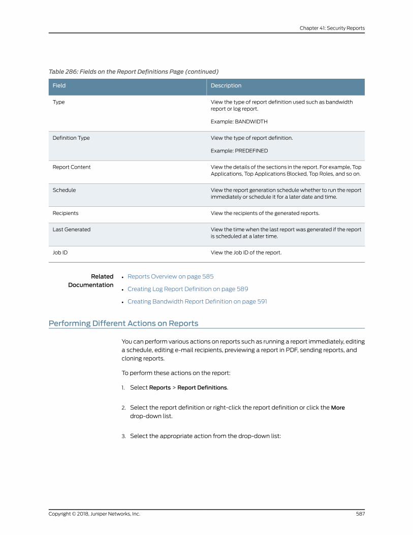
Table 286: Fields on the Report Definitions Page (continued)
DescriptionField
View the type of report definition used such as bandwidthreport or log report.
Example: BANDWIDTH
Type
View the type of report definition.
Example: PREDEFINED
Definition Type
View the details of the sections in the report. For example, TopApplications, Top Applications Blocked, Top Roles, and so on.
Report Content
View the report generation schedulewhether to run the reportimmediately or schedule it for a later date and time.
Schedule
View the recipients of the generated reports.Recipients
View the timewhen the last report was generated if the reportis scheduled at a later time.
Last Generated
View the Job ID of the report.Job ID
RelatedDocumentation
Reports Overview on page 585•
• Creating Log Report Definition on page 589
• Creating Bandwidth Report Definition on page 591
Performing Different Actions on Reports
You can perform various actions on reports such as running a report immediately, editing
a schedule, editing e-mail recipients, previewing a report in PDF, sending reports, and
cloning reports.
To perform these actions on the report:
1. Select Reports > Report Definitions.
2. Select the report definition or right-click the report definition or click theMore
drop-down list.
3. Select the appropriate action from the drop-down list:
587Copyright © 2018, Juniper Networks, Inc.
Chapter 41: Security Reports
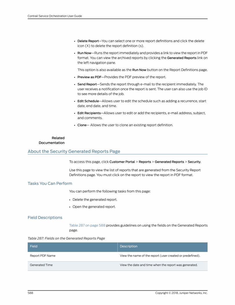
• Delete Report—You can select one or more report definitions and click the delete
icon (X) to delete the report definition (s).
• RunNow—Runs the report immediately andprovides a link to view the report in PDF
format. You can view the archived reports by clicking the Generated Reports link on
the left navigation pane.
This option is also available as the Run Now button on the Report Definitions page.
• Preview as PDF—Provides the PDF preview of the report.
• Send Report—Sends the report through e-mail to the recipient immediately. The
user receives a notification once the report is sent. The user can also use the job ID
to seemore details of the job.
• Edit Schedule—Allows user to edit the schedule such as adding a recurrence, start
date, end date, and time.
• Edit Recipients—Allows user to edit or add the recipients, e-mail address, subject,
and comments.
• Clone—Allows the user to clone an existing report definition.
RelatedDocumentation
About the Security Generated Reports Page
To access this page, click Customer Portal > Reports > Generated Reports > Security.
Use this page to view the list of reports that are generated from the Security Report
Definitions page. Youmust click on the report to view the report in PDF format.
Tasks You Can Perform
You can perform the following tasks from this page:
• Delete the generated report.
• Open the generated report.
Field Descriptions
Table 287 on page 588 provides guidelines on using the fields on the Generated Reports
page.
Table 287: Fields on the Generated Reports Page
DescriptionField
View the name of the report (user created or predefined).Report PDF Name
View the date and time when the report was generated.Generated Time
Copyright © 2018, Juniper Networks, Inc.588
Contrail Service Orchestration User Guide
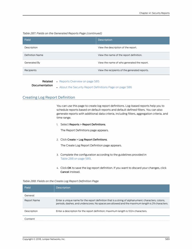
Table 287: Fields on the Generated Reports Page (continued)
DescriptionField
View the description of the report.Description
View the name of the report definition.Definition Name
View the name of who generated the report.Generated By
View the recipients of the generated reports.Recipients
RelatedDocumentation
Reports Overview on page 585•
• About the Security Report Definitions Page on page 586
Creating Log Report Definition
You can use this page to create log report definitions. Log-based reports help you to
schedule reports based on default reports and default defined filters. You can also
generate reports with additional data criteria, including filters, aggregation criteria, and
time range.
1. Select Reports > Report Definitions.
The Report Definitions page appears.
2. Click Create > Log Report Definitions.
The Create Log Report Definition page appears.
3. Complete the configuration according to the guidelines provided in
Table 288 on page 589.
4. ClickOK to save the log report definition. If you want to discard your changes, click
Cancel instead.
Table 288: Fields on the Create Log Report Definition Page
DescriptionField
General
Enter a unique name for the report definition that is a string of alphanumeric characters, colons,periods, dashes, andunderscores. No spaces are allowedand themaximum length is 29 characters.
Report Name
Enter a description for the report definition; maximum length is 1024 characters.Description
Content
589Copyright © 2018, Juniper Networks, Inc.
Chapter 41: Security Reports
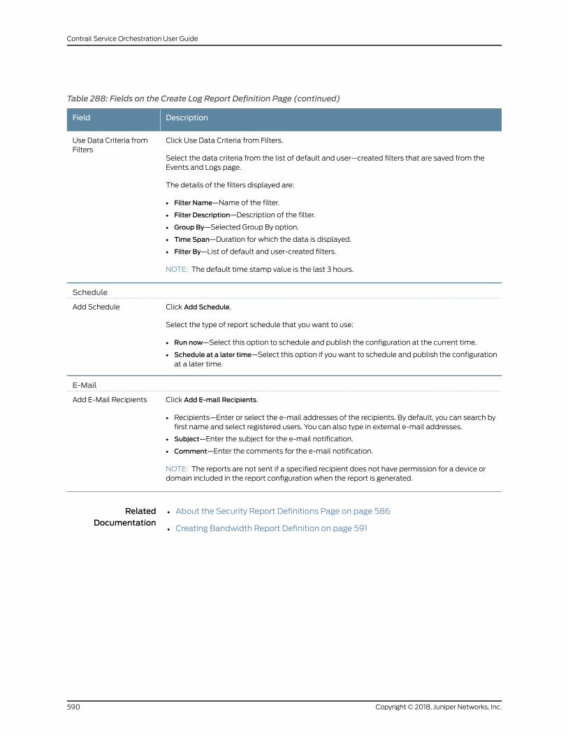
Table 288: Fields on the Create Log Report Definition Page (continued)
DescriptionField
Click Use Data Criteria from Filters.
Select the data criteria from the list of default and user--created filters that are saved from theEvents and Logs page.
The details of the filters displayed are:
• Filter Name—Name of the filter.
• Filter Description—Description of the filter.
• Group By—Selected Group By option.
• Time Span—Duration for which the data is displayed.
• Filter By—List of default and user-created filters.
NOTE: The default time stamp value is the last 3 hours.
Use Data Criteria fromFilters
Schedule
Click Add Schedule.
Select the type of report schedule that you want to use:
• Run now—Select this option to schedule and publish the configuration at the current time.
• Schedule at a later time—Select this option if you want to schedule and publish the configurationat a later time.
Add Schedule
Click Add E-mail Recipients.
• Recipients—Enter or select the e-mail addresses of the recipients. By default, you can search byfirst name and select registered users. You can also type in external e-mail addresses.
• Subject—Enter the subject for the e-mail notification.
• Comment—Enter the comments for the e-mail notification.
NOTE: The reports are not sent if a specified recipient does not have permission for a device ordomain included in the report configuration when the report is generated.
Add E-Mail Recipients
RelatedDocumentation
About the Security Report Definitions Page on page 586•
• Creating Bandwidth Report Definition on page 591
Copyright © 2018, Juniper Networks, Inc.590
Contrail Service Orchestration User Guide
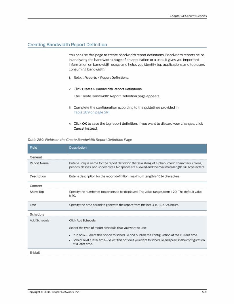
Creating Bandwidth Report Definition
You can use this page to create bandwidth report definitions. Bandwidth reports helps
in analyzing the bandwidth usage of an application or a user. It gives you important
information on bandwidth usage and helps you identify top applications and top users
consuming bandwidth.
1. Select Reports > Report Definitions.
2. Click Create > Bandwidth Report Definitions.
The Create Bandwidth Report Definition page appears.
3. Complete the configuration according to the guidelines provided in
Table 289 on page 591.
4. ClickOK to save the log report definition. If you want to discard your changes, click
Cancel instead.
Table 289: Fields on the Create Bandwidth Report Definition Page
DescriptionField
General
Enter a unique name for the report definition that is a string of alphanumeric characters, colons,periods, dashes, andunderscores.Nospacesareallowedand themaximumlength is63characters.
Report Name
Enter a description for the report definition; maximum length is 1024 characters.Description
Content
Specify the number of top events to be displayed. The value ranges from 1-20. The default valueis 10.
Show Top
Specify the time period to generate the report from the last 3, 6, 12, or 24 hours.Last
Schedule
Click Add Schedule.
Select the type of report schedule that you want to use:
• Run now—Select this option to schedule and publish the configuration at the current time.
• Schedule at a later time—Select this option if youwant to schedule andpublish the configurationat a later time.
Add Schedule
591Copyright © 2018, Juniper Networks, Inc.
Chapter 41: Security Reports
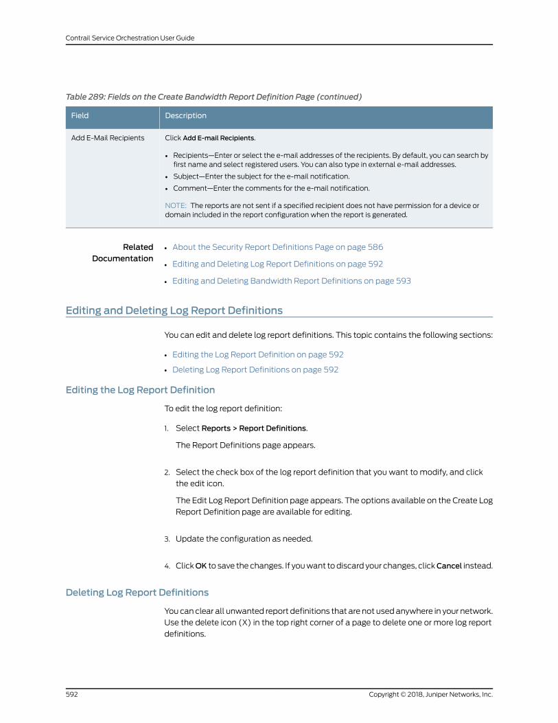
Table 289: Fields on the Create Bandwidth Report Definition Page (continued)
DescriptionField
Click Add E-mail Recipients.
• Recipients—Enter or select the e-mail addresses of the recipients. By default, you can search byfirst name and select registered users. You can also type in external e-mail addresses.
• Subject—Enter the subject for the e-mail notification.
• Comment—Enter the comments for the e-mail notification.
NOTE: The reports are not sent if a specified recipient does not have permission for a device ordomain included in the report configuration when the report is generated.
Add E-Mail Recipients
RelatedDocumentation
About the Security Report Definitions Page on page 586•
• Editing and Deleting Log Report Definitions on page 592
• Editing and Deleting Bandwidth Report Definitions on page 593
Editing and Deleting Log Report Definitions
You can edit and delete log report definitions. This topic contains the following sections:
• Editing the Log Report Definition on page 592
• Deleting Log Report Definitions on page 592
Editing the Log Report Definition
To edit the log report definition:
1. Select Reports > Report Definitions.
The Report Definitions page appears.
2. Select the check box of the log report definition that you want to modify, and click
the edit icon.
The Edit Log Report Definition page appears. The options available on the Create Log
Report Definition page are available for editing.
3. Update the configuration as needed.
4. ClickOK to save the changes. If youwant todiscard your changes, clickCancel instead.
Deleting Log Report Definitions
Youcan clear all unwanted report definitions that are not usedanywhere in your network.
Use the delete icon (X) in the top right corner of a page to delete one or more log report
definitions.
Copyright © 2018, Juniper Networks, Inc.592
Contrail Service Orchestration User Guide
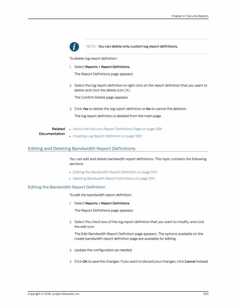
NOTE: You can delete only custom log report definitions.
To delete log report definition:
1. Select Reports > Report Definitions.
The Report Definitions page appears.
2. Select the log report definition or right click on the report definition that you want to
delete and click the delete icon (X).
The Confirm Delete page appears.
3. Click Yes to delete the log report definition or No to cancel the deletion.
The log report definition is deleted from themain page.
RelatedDocumentation
About the Security Report Definitions Page on page 586•
• Creating Log Report Definition on page 589
Editing and Deleting Bandwidth Report Definitions
You can edit and delete bandwidth report definitions. This topic contains the following
sections:
• Editing the Bandwidth Report Definition on page 593
• Deleting Bandwidth Report Definitions on page 594
Editing the Bandwidth Report Definition
To edit the bandwidth report definition:
1. Select Reports > Report Definitions.
The Report Definitions page appears.
2. Select the check box of the log report definition that you want to modify, and click
the edit icon.
The Edit Bandwidth Report Definition page appears. The options available on the
create bandwidth report definition page are available for editing.
3. Update the configuration as needed.
4. ClickOK to save the changes. If youwant todiscard your changes, clickCancel instead.
593Copyright © 2018, Juniper Networks, Inc.
Chapter 41: Security Reports
Deleting Bandwidth Report Definitions
Youcan clear all unwanted report definitions that are not usedanywhere in your network.
Use the delete icon (X) in the top right corner of a page to delete one or more log report
definitions.
NOTE: You can delete only custom bandwidth report definitions.
To delete bandwidth report definition:
1. Select Reports > Report Definitions.
The Report Definitions page appears.
2. Select the bandwidth report definition or right click on the report definition that you
want to delete and click the X icon.
The Confirm Delete page appears.
3. Click Yes to delete the bandwidth report definition or No to cancel the deletion.
The bandwidth report definition is deleted from themain page.
RelatedDocumentation
• About the Security Report Definitions Page on page 586
• Creating Bandwidth Report Definition on page 591
Copyright © 2018, Juniper Networks, Inc.594
Contrail Service Orchestration User Guide
CHAPTER 42
SD-WAN Reports
• About the SD-WAN Report Definitions Page on page 595
• Editing and Deleting SD-WAN Report Definitions on page 596
• Creating SD-WAN Tenant Performance Report Definition on page 598
• Creating SD-WAN Site Performance Report Definition on page 600
• About the SD-WAN Generated Reports Page on page 602
About the SD-WANReport Definitions Page
To access this page, click Customer Portal > Reports > Report Definitions > SD-WAN.
You canuse theSD-WANReport Definitions page to viewa list of predefined and custom
report definitions. You can use the predefined report definition as-is, or you can create
custom report definitions. You can use SD-WAN reports to view the SLA performance
of SD-WAN sites in a tenant.
You can perform various actions on reports such as run a report immediately, edit a
schedule, edit e-mail recipients, preview a report in PDF, send reports, and clone reports,
using this page.
Youmust create a report definition to generate a report. You can generate an SLA
performance report for all sites in a tenant or for specific sites in a tenant.
Tasks You Can Perform
You can perform the following tasks from this page:
• CreateSD-WANtenantperformance report definitions. See “CreatingSD-WANTenant
Performance Report Definition” on page 598
• Create SD-WAN site performance report definitions. See “Creating SD-WAN Site
Performance Report Definition” on page 600
• Run a report immediately, edit a schedule, edit e-mail recipients, preview a report in
PDF, send reports, and clone reports. See “Performing Different Actions on Reports”
on page 587
595Copyright © 2018, Juniper Networks, Inc.
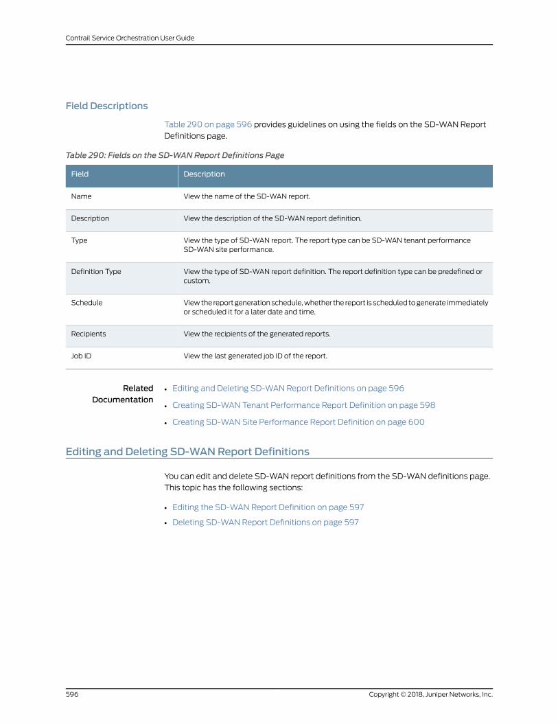
Field Descriptions
Table 290 on page 596 provides guidelines on using the fields on the SD-WAN Report
Definitions page.
Table 290: Fields on the SD-WANReport Definitions Page
DescriptionField
View the name of the SD-WAN report.Name
View the description of the SD-WAN report definition.Description
View the type of SD-WAN report. The report type can be SD-WAN tenant performanceSD-WAN site performance.
Type
View the type of SD-WAN report definition. The report definition type can be predefined orcustom.
Definition Type
Viewthe reportgenerationschedule,whether the report is scheduled togenerate immediatelyor scheduled it for a later date and time.
Schedule
View the recipients of the generated reports.Recipients
View the last generated job ID of the report.Job ID
RelatedDocumentation
Editing and Deleting SD-WAN Report Definitions on page 596•
• Creating SD-WAN Tenant Performance Report Definition on page 598
• Creating SD-WAN Site Performance Report Definition on page 600
Editing and Deleting SD-WANReport Definitions
You can edit and delete SD-WAN report definitions from the SD-WAN definitions page.
This topic has the following sections:
• Editing the SD-WAN Report Definition on page 597
• Deleting SD-WAN Report Definitions on page 597
Copyright © 2018, Juniper Networks, Inc.596
Contrail Service Orchestration User Guide
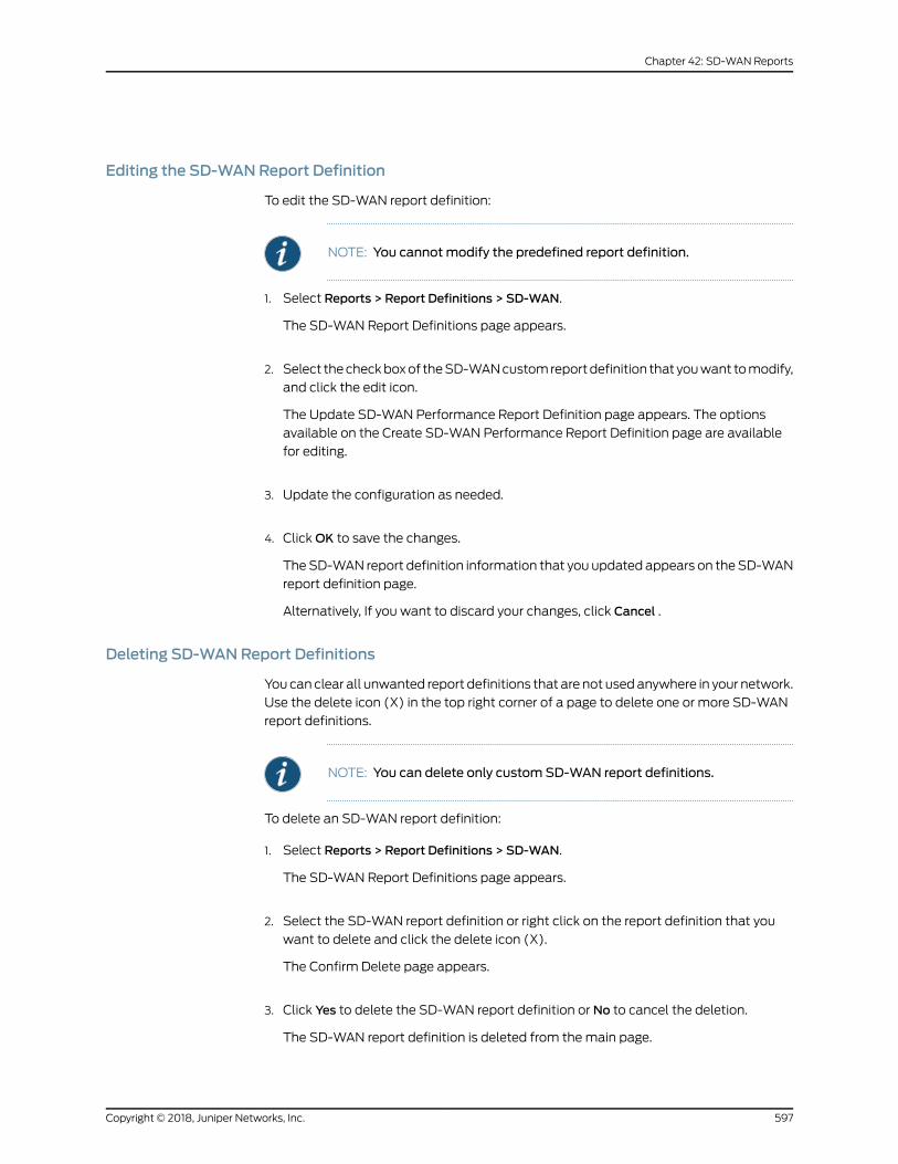
Editing the SD-WANReport Definition
To edit the SD-WAN report definition:
NOTE: You cannot modify the predefined report definition.
1. Select Reports > Report Definitions > SD-WAN.
The SD-WAN Report Definitions page appears.
2. Select thecheckboxof theSD-WANcustomreportdefinition that youwant tomodify,
and click the edit icon.
The Update SD-WAN Performance Report Definition page appears. The options
available on the Create SD-WAN Performance Report Definition page are available
for editing.
3. Update the configuration as needed.
4. ClickOK to save the changes.
TheSD-WAN report definition information that you updated appears on theSD-WAN
report definition page.
Alternatively, If you want to discard your changes, click Cancel .
Deleting SD-WANReport Definitions
Youcan clear all unwanted report definitions that are not usedanywhere in your network.
Use the delete icon (X) in the top right corner of a page to delete one or more SD-WAN
report definitions.
NOTE: You can delete only custom SD-WAN report definitions.
To delete an SD-WAN report definition:
1. Select Reports > Report Definitions > SD-WAN.
The SD-WAN Report Definitions page appears.
2. Select the SD-WAN report definition or right click on the report definition that you
want to delete and click the delete icon (X).
The Confirm Delete page appears.
3. Click Yes to delete the SD-WAN report definition or No to cancel the deletion.
The SD-WAN report definition is deleted from themain page.
597Copyright © 2018, Juniper Networks, Inc.
Chapter 42: SD-WAN Reports
RelatedDocumentation
About the SD-WAN Report Definitions Page on page 595•
Creating SD-WAN Tenant Performance Report Definition
Use this page to create SD-WAN report definitions for all sites in a tenant and generate
the report based on the definitions. You can also schedule a report generation and add
one or more recipients to whom you want to send the reports.
TheSD-WAN tenant performance report includesSLAperformanceof the followingSLA
events:
• Top Applications By Bandwidth
• Top Sites Not Meeting SLA
• Top Sites Meeting SLA with Switching
• Sites Meeting SLA without Switching
NOTE: Only users with the MSP Administrator or Tenant Administrator rolecan create SD-WAN tenant performance report definitions.
To create SD-WAN tenant report definition:
1. Select Reports > Report Definitions > SD-WAN.
The SD-WAN Report Definitions page appears.
2. Click Create > Performance.
The Create SD-WAN Tenant Performance Report Definition page appears.
3. Complete the configuration according to the guidelines provided in
Table 291 on page 598.
4. ClickOK to save the report definition.
An SD-WAN tenant performance report definition is created and saved in the report
definitions page.
Alternatively, if you want to discard your changes, click Cancel.
Table 291: Fields on the Create Tenant Performance Report Definition
DescriptionField
General
Enter a unique name for the report definition. You can use a string of alphanumeric characters,colons, periods, dashes, and underscores. No spaces are allowed and themaximum length is 63characters.
Report Name
Copyright © 2018, Juniper Networks, Inc.598
Contrail Service Orchestration User Guide
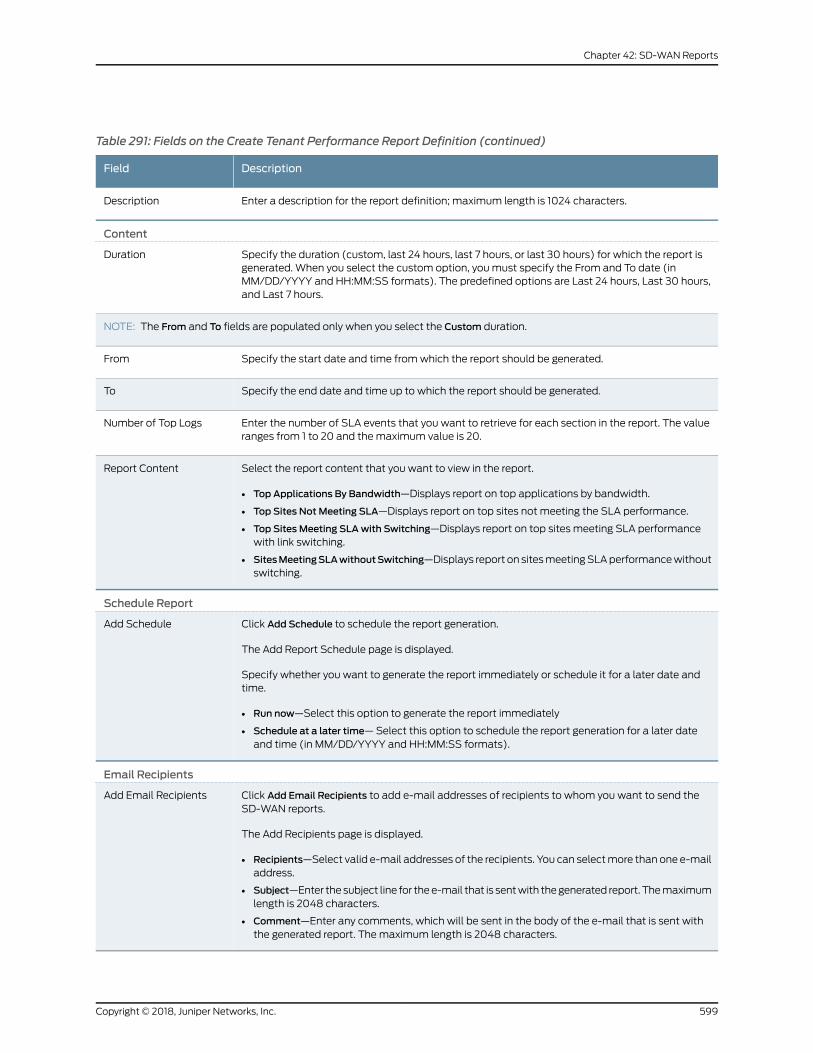
Table 291: Fields on the Create Tenant Performance Report Definition (continued)
DescriptionField
Enter a description for the report definition; maximum length is 1024 characters.Description
Content
Specify the duration (custom, last 24 hours, last 7 hours, or last 30 hours) for which the report isgenerated. When you select the custom option, youmust specify the From and To date (inMM/DD/YYYY and HH:MM:SS formats). The predefined options are Last 24 hours, Last 30 hours,and Last 7 hours.
Duration
NOTE: The From and To fields are populated only when you select the Custom duration.
Specify the start date and time fromwhich the report should be generated.From
Specify the end date and time up to which the report should be generated.To
Enter the number of SLA events that you want to retrieve for each section in the report. The valueranges from 1 to 20 and themaximum value is 20.
Number of Top Logs
Select the report content that you want to view in the report.
• Top Applications By Bandwidth—Displays report on top applications by bandwidth.
• Top Sites Not Meeting SLA—Displays report on top sites not meeting the SLA performance.
• Top Sites Meeting SLAwith Switching—Displays report on top sites meeting SLA performancewith link switching.
• SitesMeetingSLAwithoutSwitching—Displays report on sitesmeetingSLAperformancewithoutswitching.
Report Content
Schedule Report
Click Add Schedule to schedule the report generation.
The Add Report Schedule page is displayed.
Specify whether you want to generate the report immediately or schedule it for a later date andtime.
• Run now—Select this option to generate the report immediately
• Schedule at a later time—Select this option to schedule the report generation for a later dateand time (in MM/DD/YYYY and HH:MM:SS formats).
Add Schedule
Email Recipients
Click Add Email Recipients to add e-mail addresses of recipients to whom you want to send theSD-WAN reports.
The Add Recipients page is displayed.
• Recipients—Select valid e-mail addresses of the recipients. You can selectmore than one e-mailaddress.
• Subject—Enter the subject line for thee-mail that is sentwith thegenerated report. Themaximumlength is 2048 characters.
• Comment—Enter any comments, which will be sent in the body of the e-mail that is sent withthe generated report. Themaximum length is 2048 characters.
Add Email Recipients
599Copyright © 2018, Juniper Networks, Inc.
Chapter 42: SD-WAN Reports
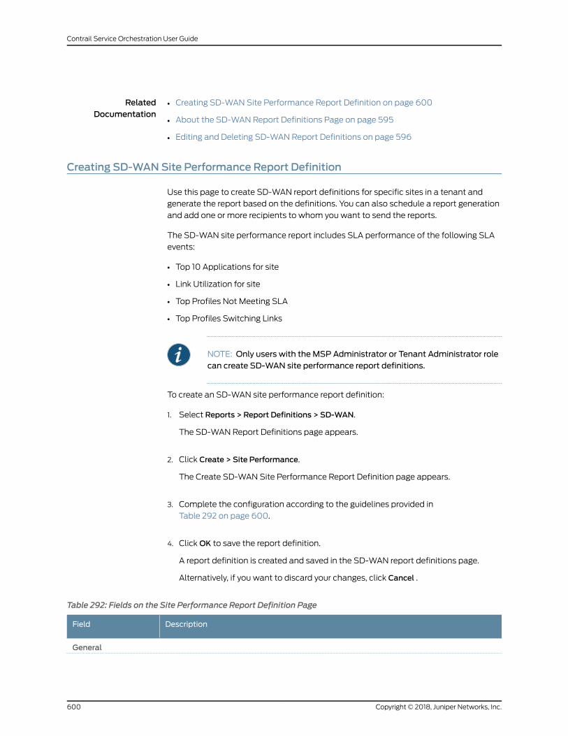
RelatedDocumentation
Creating SD-WAN Site Performance Report Definition on page 600•
• About the SD-WAN Report Definitions Page on page 595
• Editing and Deleting SD-WAN Report Definitions on page 596
Creating SD-WANSite Performance Report Definition
Use this page to create SD-WAN report definitions for specific sites in a tenant and
generate the report based on the definitions. You can also schedule a report generation
and add one or more recipients to whom you want to send the reports.
The SD-WAN site performance report includes SLA performance of the following SLA
events:
• Top 10 Applications for site
• Link Utilization for site
• Top Profiles Not Meeting SLA
• Top Profiles Switching Links
NOTE: Only users with the MSP Administrator or Tenant Administrator rolecan create SD-WAN site performance report definitions.
To create an SD-WAN site performance report definition:
1. Select Reports > Report Definitions > SD-WAN.
The SD-WAN Report Definitions page appears.
2. Click Create > Site Performance.
The Create SD-WAN Site Performance Report Definition page appears.
3. Complete the configuration according to the guidelines provided in
Table 292 on page 600.
4. ClickOK to save the report definition.
A report definition is created and saved in the SD-WAN report definitions page.
Alternatively, if you want to discard your changes, click Cancel .
Table 292: Fields on the Site Performance Report Definition Page
DescriptionField
General
Copyright © 2018, Juniper Networks, Inc.600
Contrail Service Orchestration User Guide
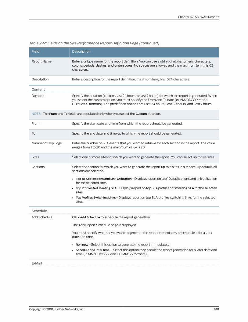
Table 292: Fields on the Site Performance Report Definition Page (continued)
DescriptionField
Enter a unique name for the report definition. You can use a string of alphanumeric characters,colons, periods, dashes, and underscores. No spaces are allowed and themaximum length is 63characters.
Report Name
Enter a description for the report definition; maximum length is 1024 characters.Description
Content
Specify the duration (custom, last 24 hours, or last 7 hours) for which the report is generated.Whenyou select the custom option, youmust specify the From and To date (in MM/DD/YYYY andHH:MM:SS formats). The predefined options are Last 24 hours, Last 30 hours, and Last 7 hours.
Duration
NOTE: The From and To fields are populated only when you select the Custom duration.
Specify the start date and time fromwhich the report should be generated.From
Specify the end date and time up to which the report should be generated.To
Enter the number of SLA events that you want to retrieve for each section in the report. The valueranges from 1 to 20 and themaximum value is 20.
Number of Top Logs
Select one or more sites for which you want to generate the report. You can select up to five sites.Sites
Select the section for which you want to generate the report up to 5 sites in a tenant. By default, allsections are selected.
• Top 10Applications and Link Utilization—Displays report on top 10 applications and link utilizationfor the selected sites.
• TopProfilesNotMeetingSLA—Displays reporton topSLAprofilesnotmeetingSLAfor theselectedsites.
• Top Profiles Switching Links—Displays report on top SLA profiles switching links for the selectedsites.
Sections
Schedule
Click Add Schedule to schedule the report generation.
The Add Report Schedule page is displayed.
Youmust specify whether you want to generate the report immediately or schedule it for a laterdate and time.
• Run now—Select this option to generate the report immediately
• Schedule at a later time—Select this option to schedule the report generation for a later date andtime (in MM/DD/YYYY and HH:MM:SS formats).
Add Schedule
601Copyright © 2018, Juniper Networks, Inc.
Chapter 42: SD-WAN Reports
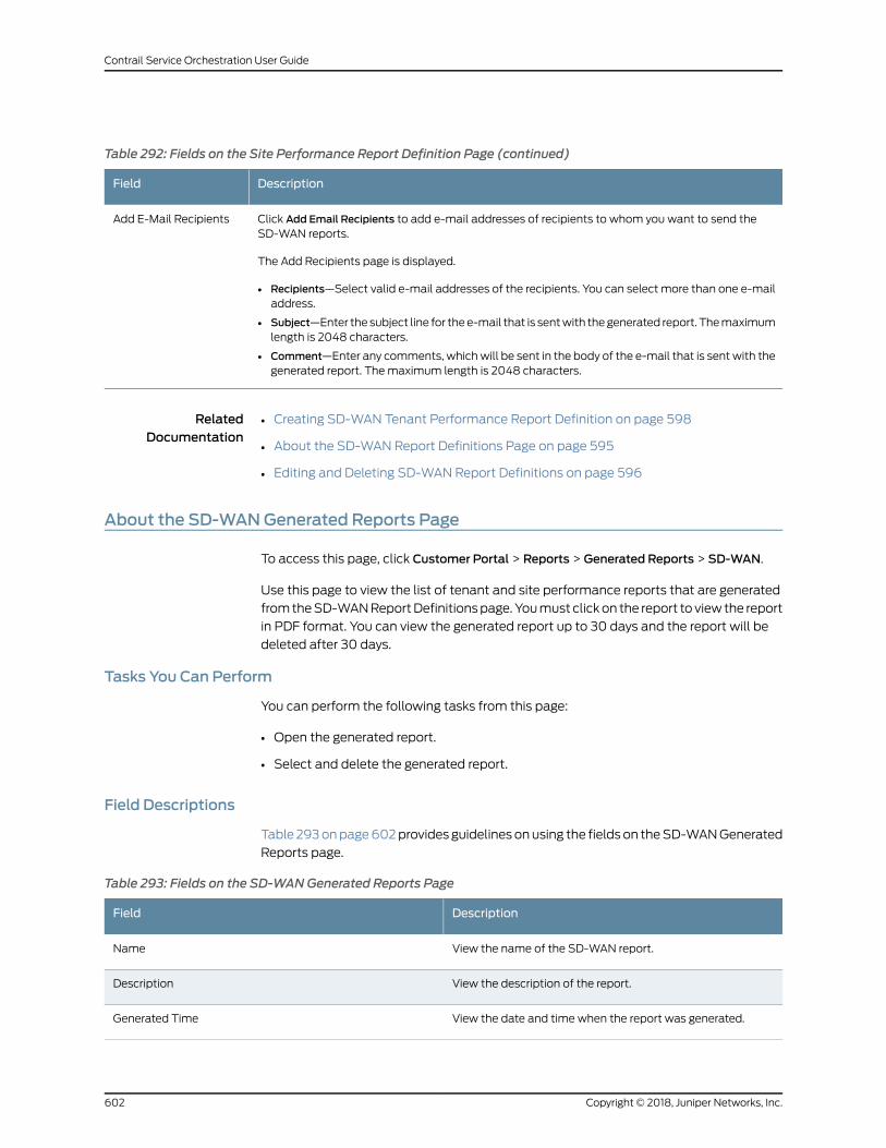
Table 292: Fields on the Site Performance Report Definition Page (continued)
DescriptionField
Click Add Email Recipients to add e-mail addresses of recipients to whom you want to send theSD-WAN reports.
The Add Recipients page is displayed.
• Recipients—Select valid e-mail addresses of the recipients. You can select more than one e-mailaddress.
• Subject—Enter the subject line for thee-mail that is sentwith thegenerated report. Themaximumlength is 2048 characters.
• Comment—Enter any comments, whichwill be sent in the body of the e-mail that is sentwith thegenerated report. Themaximum length is 2048 characters.
Add E-Mail Recipients
RelatedDocumentation
Creating SD-WAN Tenant Performance Report Definition on page 598•
• About the SD-WAN Report Definitions Page on page 595
• Editing and Deleting SD-WAN Report Definitions on page 596
About the SD-WANGenerated Reports Page
To access this page, click Customer Portal > Reports > Generated Reports > SD-WAN.
Use this page to view the list of tenant and site performance reports that are generated
fromtheSD-WANReportDefinitionspage.Youmust clickon the report to view the report
in PDF format. You can view the generated report up to 30 days and the report will be
deleted after 30 days.
Tasks You Can Perform
You can perform the following tasks from this page:
• Open the generated report.
• Select and delete the generated report.
Field Descriptions
Table 293onpage602provides guidelines onusing the fields on theSD-WANGenerated
Reports page.
Table 293: Fields on the SD-WANGenerated Reports Page
DescriptionField
View the name of the SD-WAN report.Name
View the description of the report.Description
View the date and time when the report was generated.Generated Time
Copyright © 2018, Juniper Networks, Inc.602
Contrail Service Orchestration User Guide
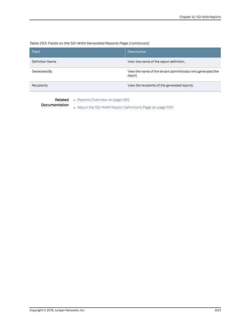
Table 293: Fields on the SD-WANGenerated Reports Page (continued)
DescriptionField
View the name of the report definition.Definition Name
View the nameof the tenant administratorwho generated thereport.
Generated By
View the recipients of the generated reports.Recipients
RelatedDocumentation
• Reports Overview on page 585
• About the SD-WAN Report Definitions Page on page 595
603Copyright © 2018, Juniper Networks, Inc.
Chapter 42: SD-WAN Reports

Copyright © 2018, Juniper Networks, Inc.604
Contrail Service Orchestration User Guide
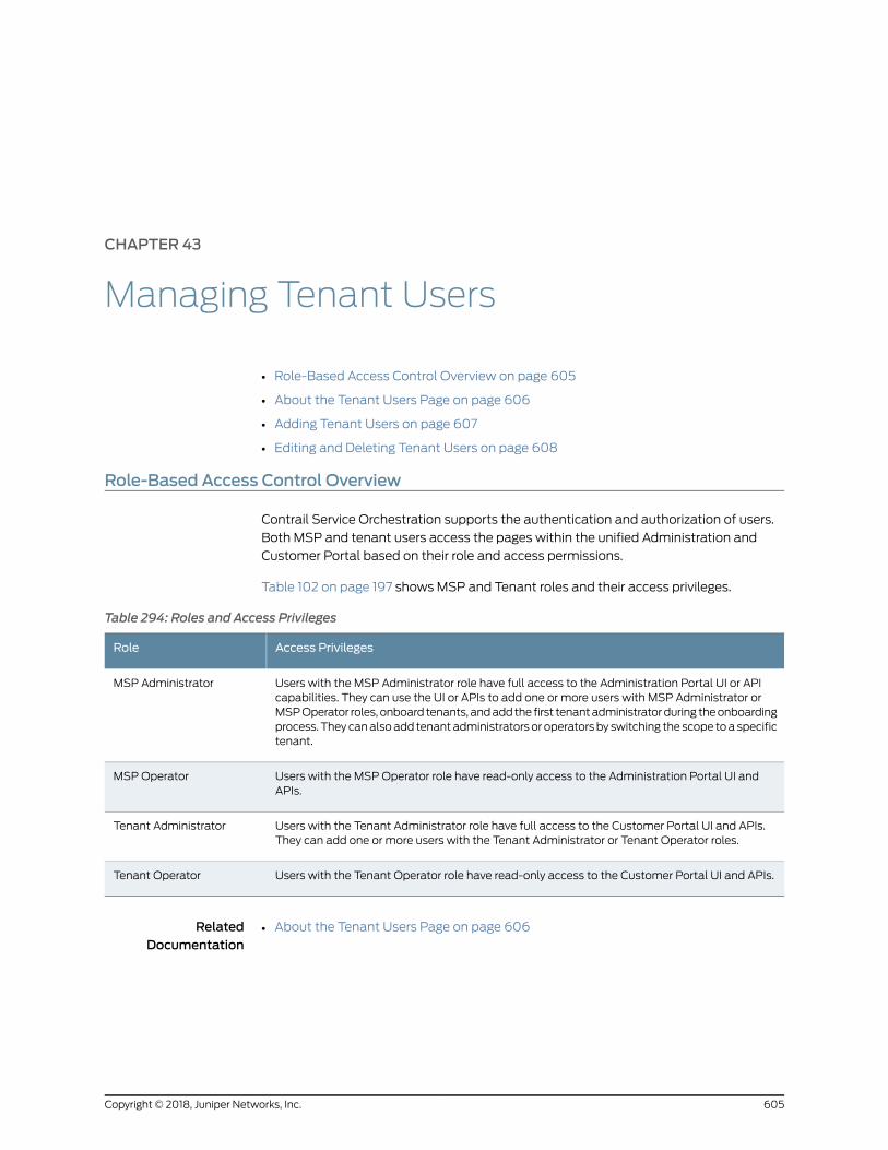
CHAPTER 43
Managing Tenant Users
• Role-Based Access Control Overview on page 605
• About the Tenant Users Page on page 606
• Adding Tenant Users on page 607
• Editing and Deleting Tenant Users on page 608
Role-Based Access Control Overview
Contrail Service Orchestration supports the authentication and authorization of users.
Both MSP and tenant users access the pages within the unified Administration and
Customer Portal based on their role and access permissions.
Table 102 on page 197 shows MSP and Tenant roles and their access privileges.
Table 294: Roles and Access Privileges
Access PrivilegesRole
Users with the MSP Administrator role have full access to the Administration Portal UI or APIcapabilities. They can use the UI or APIs to add one or more users with MSP Administrator orMSPOperator roles, onboard tenants, andaddthe first tenantadministratorduring theonboardingprocess. Theycanalsoadd tenantadministratorsor operatorsby switching the scope toaspecifictenant.
MSP Administrator
Users with the MSP Operator role have read-only access to the Administration Portal UI andAPIs.
MSP Operator
Users with the Tenant Administrator role have full access to the Customer Portal UI and APIs.They can add one or more users with the Tenant Administrator or Tenant Operator roles.
Tenant Administrator
Users with the Tenant Operator role have read-only access to the Customer Portal UI and APIs.Tenant Operator
RelatedDocumentation
About the Tenant Users Page on page 606•
605Copyright © 2018, Juniper Networks, Inc.
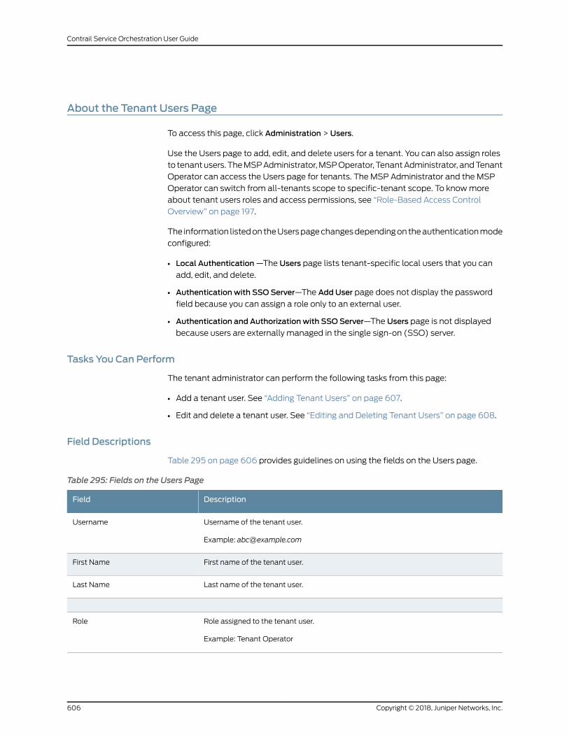
About the Tenant Users Page
To access this page, click Administration > Users.
Use the Users page to add, edit, and delete users for a tenant. You can also assign roles
to tenantusers. TheMSPAdministrator,MSPOperator, TenantAdministrator, andTenant
Operator can access the Users page for tenants. The MSP Administrator and the MSP
Operator can switch from all-tenants scope to specific-tenant scope. To knowmore
about tenant users roles and access permissions, see “Role-Based Access Control
Overview” on page 197.
The information listedon theUserspagechangesdependingon theauthenticationmode
configured:
• Local Authentication—The Users page lists tenant-specific local users that you can
add, edit, and delete.
• Authentication with SSO Server—The Add User page does not display the password
field because you can assign a role only to an external user.
• Authentication and Authorization with SSO Server—The Users page is not displayed
because users are externally managed in the single sign-on (SSO) server.
Tasks You Can Perform
The tenant administrator can perform the following tasks from this page:
• Add a tenant user. See “Adding Tenant Users” on page 607.
• Edit and delete a tenant user. See “Editing and Deleting Tenant Users” on page 608.
Field Descriptions
Table 295 on page 606 provides guidelines on using the fields on the Users page.
Table 295: Fields on the Users Page
DescriptionField
Username of the tenant user.
Example: [email protected]
Username
First name of the tenant user.First Name
Last name of the tenant user.Last Name
Role assigned to the tenant user.
Example: Tenant Operator
Role
Copyright © 2018, Juniper Networks, Inc.606
Contrail Service Orchestration User Guide
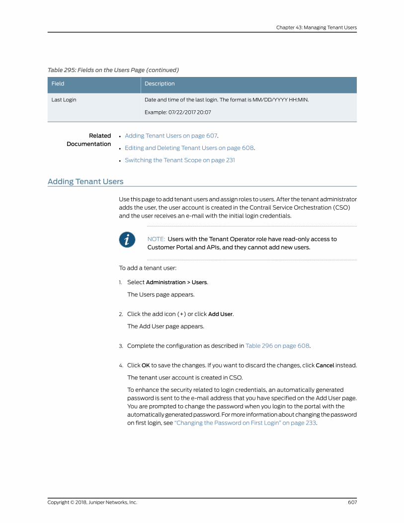
Table 295: Fields on the Users Page (continued)
DescriptionField
Date and time of the last login. The format is MM/DD/YYYY HH:MIN.
Example: 07/22/2017 20:07
Last Login
RelatedDocumentation
Adding Tenant Users on page 607.•
• Editing and Deleting Tenant Users on page 608.
• Switching the Tenant Scope on page 231
Adding Tenant Users
Use thispage toadd tenantusersandassign roles tousers. After the tenantadministrator
adds the user, the user account is created in the Contrail Service Orchestration (CSO)
and the user receives an e-mail with the initial login credentials.
NOTE: Users with the Tenant Operator role have read-only access toCustomer Portal and APIs, and they cannot add new users.
To add a tenant user:
1. Select Administration > Users.
The Users page appears.
2. Click the add icon (+) or click Add User.
The Add User page appears.
3. Complete the configuration as described in Table 296 on page 608.
4. ClickOK to save the changes. If youwant to discard the changes, clickCancel instead.
The tenant user account is created in CSO.
To enhance the security related to login credentials, an automatically generated
password is sent to the e-mail address that you have specified on the Add User page.
You are prompted to change the password when you login to the portal with the
automaticallygeneratedpassword.Formore informationaboutchanging thepassword
on first login, see “Changing the Password on First Login” on page 233.
607Copyright © 2018, Juniper Networks, Inc.
Chapter 43: Managing Tenant Users
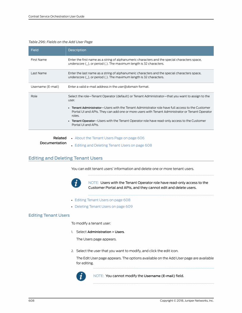
Table 296: Fields on the Add User Page
DescriptionField
Enter the first name as a string of alphanumeric characters and the special characters space,underscore (_), or period (.). Themaximum length is 32 characters.
First Name
Enter the last name as a string of alphanumeric characters and the special characters space,underscore (_), or period (.). Themaximum length is 32 characters.
Last Name
Enter a valid e-mail address in the user@domain format.Username (E-mail)
Select the role—Tenant Operator (default) or Tenant Administrator—that you want to assign to theuser.
• Tenant Administrator—Users with the Tenant Administrator role have full access to the CustomerPortal UI and APIs. They can add one or more users with Tenant Administrator or Tenant Operatorroles.
• Tenant Operator—Users with the Tenant Operator role have read-only access to the CustomerPortal UI and APIs.
Role
RelatedDocumentation
About the Tenant Users Page on page 606•
• Editing and Deleting Tenant Users on page 608
Editing and Deleting Tenant Users
You can edit tenant users’ information and delete one or more tenant users.
NOTE: Users with the Tenant Operator role have read-only access to theCustomer Portal and APIs, and they cannot edit and delete users.
• Editing Tenant Users on page 608
• Deleting Tenant Users on page 609
Editing Tenant Users
Tomodify a tenant user:
1. Select Administration > Users.
The Users page appears.
2. Select the user that you want to modify, and click the edit icon.
The Edit User page appears. The options available on the AddUser page are available
for editing.
NOTE: You cannot modify the Username (E-mail) field.
Copyright © 2018, Juniper Networks, Inc.608
Contrail Service Orchestration User Guide
3. Update the configuration as needed.
4. ClickOK to save the changes. If youwant todiscard your changes, clickCancel instead.
Themodified tenant user information is saved in CSO.
Deleting Tenant Users
To delete tenant users:
1. Select Administration > Users.
The Users page appears.
2. Select the users that you want to delete and click the delete icon (X).
The Confirm Delete page appears.
3. Click Yes to delete the user or No to cancel the deletion.
If you click Yes, then the user is deleted and the user account is removed from the
CSO.
RelatedDocumentation
• About the Tenant Users Page on page 606
• Adding Tenant Users on page 607
609Copyright © 2018, Juniper Networks, Inc.
Chapter 43: Managing Tenant Users

Copyright © 2018, Juniper Networks, Inc.610
Contrail Service Orchestration User Guide
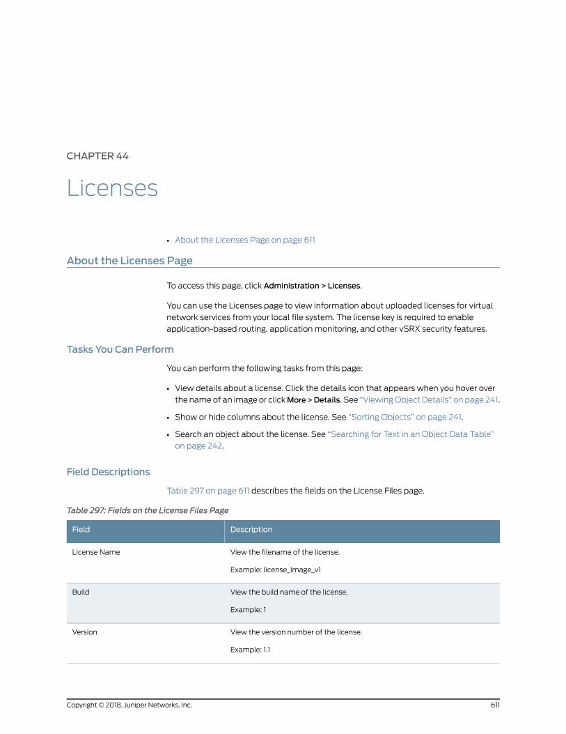
CHAPTER 44
Licenses
• About the Licenses Page on page 611
About the Licenses Page
To access this page, click Administration > Licenses.
You can use the Licenses page to view information about uploaded licenses for virtual
network services from your local file system. The license key is required to enable
application-based routing, application monitoring, and other vSRX security features.
Tasks You Can Perform
You can perform the following tasks from this page:
• View details about a license. Click the details icon that appears when you hover over
the nameof an image or clickMore>Details. See “ViewingObject Details” on page 241.
• Show or hide columns about the license. See “Sorting Objects” on page 241.
• Search an object about the license. See “Searching for Text in an Object Data Table”
on page 242.
Field Descriptions
Table 297 on page 611 describes the fields on the License Files page.
Table 297: Fields on the License Files Page
DescriptionField
View the filename of the license.
Example: license_Image_v1
License Name
View the build name of the license.
Example: 1
Build
View the version number of the license.
Example: 1.1
Version
611Copyright © 2018, Juniper Networks, Inc.
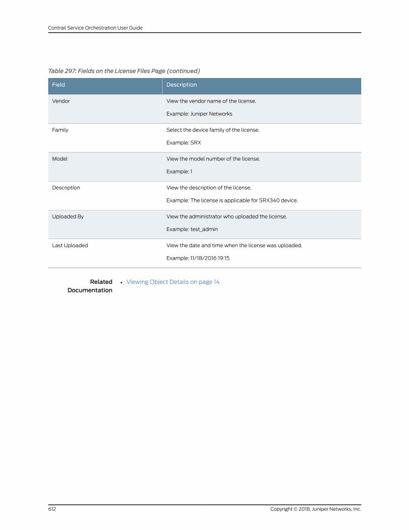
Table 297: Fields on the License Files Page (continued)
DescriptionField
View the vendor name of the license.
Example: Juniper Networks
Vendor
Select the device family of the license.
Example: SRX
Family
View themodel number of the license.
Example: 1
Model
View the description of the license.
Example: The license is applicable for SRX340 device.
Description
View the administrator who uploaded the license.
Example: test_admin
Uploaded By
View the date and time when the license was uploaded.
Example: 11/18/2016 19:15
Last Uploaded
RelatedDocumentation
• Viewing Object Details on page 14
Copyright © 2018, Juniper Networks, Inc.612
Contrail Service Orchestration User Guide
CHAPTER 45
Signature Database
• Signature Database Overview on page 613
• About the Active Database Page on page 614
• Installing Signatures on page 615
Signature Database Overview
The Application Firewall signature database includes signature definitions of attacks
and applications that can be used to identify applications for tracking firewall policies
and quality-of-service (QoS) prioritization.
Contrail Service Orchestration (CSO) enables you to download the signature database.
During a download, the complete signature database is downloaded, and the download
might take some time to complete. You can track the progress of the download by using
job details.
All of the downloaded signatures are created as a default project in read-onlymode. The
configurations that are downloaded are also saved as a default project.
RelatedDocumentation
About the Active Database Page on page 614•
• Installing Signatures on page 615
613Copyright © 2018, Juniper Networks, Inc.
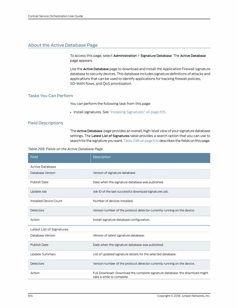
About the Active Database Page
To access this page, select Administration > Signature Database. The Active Database
page appears.
Use the Active Database page to download and install the Application Firewall signature
database to security devices. This database includes signature definitions of attacks and
applications that can be used to identify applications for tracking firewall policies,
SD-WAN flows, and QoS prioritization.
Tasks You Can Perform
You can perform the following task from this page:
• Install signatures. See “Installing Signatures” on page 615.
Field Descriptions
TheActiveDatabase pageprovides anoverall, high-level viewof your signature database
settings. The Latest List of Signatures table provides a search option that you can use to
search for the signature youwant. Table 298onpage614describes the fieldson this page.
Table 298: Fields on the Active Database Page
DescriptionField
Active Database
Version of signature database.Database Version
Date when the signature database was published.Publish Date
Job ID of the last successful download signatures job.Update Job
Number of devices installed.Installed Device Count
Version number of the protocol detector currently running on the device.Detectors
Install signature database configuration.Action
Latest List of Signatures
Version of latest signature database.Database Version
Date when the signature database was published.Publish Date
List of updated signature details for the selected database.Update Summary
Version number of the protocol detector currently running on the device.Detectors
Full Download–Download the complete signature database; the downloadmighttake a while to complete.
Action
Copyright © 2018, Juniper Networks, Inc.614
Contrail Service Orchestration User Guide
RelatedDocumentation
Signature Database Overview on page 613•
• Installing Signatures on page 615
Installing Signatures
After the signature database is downloaded, you can install the active database.
To install the signature database:
1. Select Administration > Signature Database.
2. Click Install Signatures.
The Install Signatures page appears.
3. Youcanview the summaryof active signaturedatabaseversion,whichwill be installed
on your device.
4. Click the check box next to the devices on which you want to install the signature
database.
You can also search, sort, or filter this information.
5. Select Run now to set the signature database to automatically install immediately.
6. SelectScheduleata later time to set thesignaturedatabase toautomaticallydownload
at the specified time and to take the following actions:
a. Choose a date by clicking the date picker icon.
b. Enter the time.
c. Select the time format from the drop-down list.
7. ClickOK.
The signature database installation is complete.
RelatedDocumentation
• Signature Database Overview on page 613
• About the Active Database Page on page 614
615Copyright © 2018, Juniper Networks, Inc.
Chapter 45: Signature Database

Copyright © 2018, Juniper Networks, Inc.616
Contrail Service Orchestration User Guide
CHAPTER 46
Managing Certificates
• Certificates Overview on page 617
• About the Certificates Page on page 617
• Importing a Certificate on page 619
• Installing and Uninstalling Certificates on page 621
Certificates Overview
SSL uses public–private key technology that requires a private key paired with an
authentication certificate for the SSL service. An SSL certificate includes identifying
information such as a public key and a signature issued by a certificate authority (CA).
CAs are entities that validate identities and issue certificates. A CA can issuemultiple
certificates in the form of a tree structure. A root certificate is the topmost certificate of
the tree, the private key of which is used to sign other certificates. All certificates
immediately below the root certificate inherit the signature or trustworthiness of the root
certificate. This is somewhat like the notarizing of an identity. You can configure a root
CA certificate by first obtaining a root CA certificate (by either generating a self-signed
one or importing one) and then applying it to an SSL proxy profile.
NOTE: SSL certificates are used for the SSL forward proxy feature in CSO.
RelatedDocumentation
SSL Forward Proxy Overview on page 481•
• About the SSL Proxy Profiles Page on page 494
About the Certificates Page
To access this page, select Administration > Certificates in Customer Portal.
Use this page to view andmanage SSL certificates. You can import a root certificate or
a trusted certificate (directly froma file or by pasting the content) and install a certificate
on a site.
617Copyright © 2018, Juniper Networks, Inc.
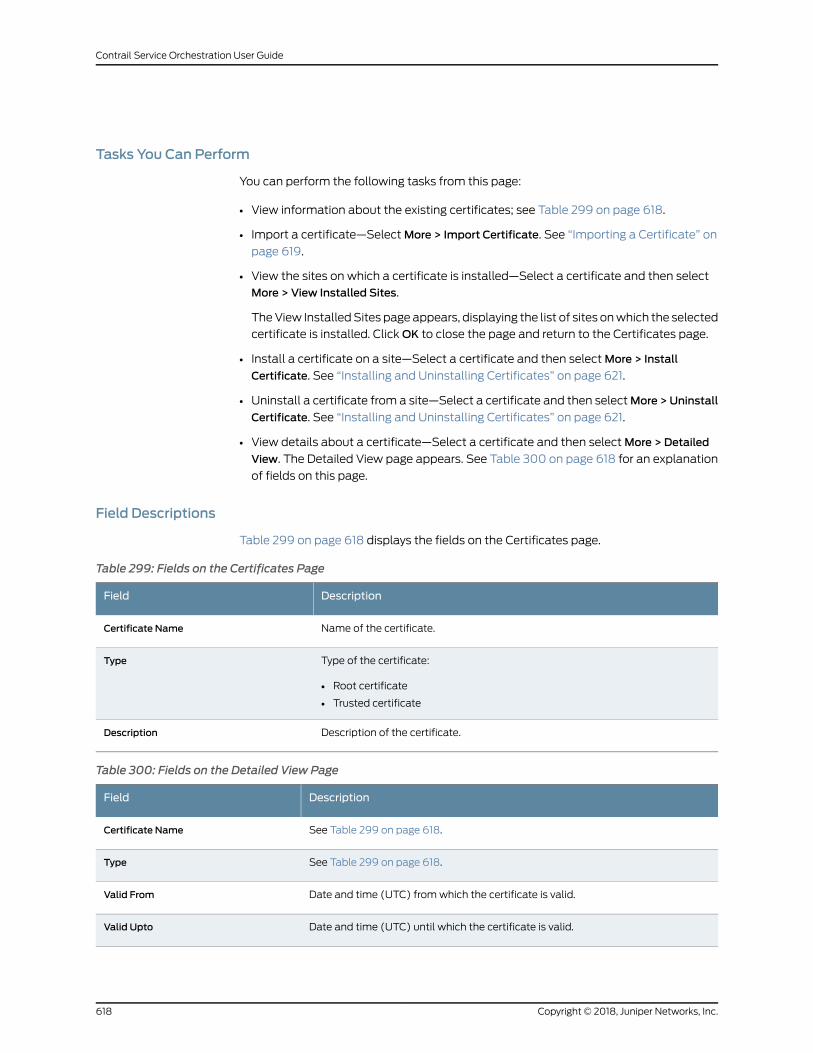
Tasks You Can Perform
You can perform the following tasks from this page:
• View information about the existing certificates; see Table 299 on page 618.
• Import a certificate—SelectMore > Import Certificate. See “Importing a Certificate” on
page 619.
• View the sites on which a certificate is installed—Select a certificate and then select
More > View Installed Sites.
TheView InstalledSites page appears, displaying the list of sites onwhich the selected
certificate is installed. ClickOK to close the page and return to the Certificates page.
• Install a certificate on a site—Select a certificate and then selectMore > Install
Certificate. See “Installing and Uninstalling Certificates” on page 621.
• Uninstall a certificate from a site—Select a certificate and then selectMore >Uninstall
Certificate. See “Installing and Uninstalling Certificates” on page 621.
• View details about a certificate—Select a certificate and then selectMore > Detailed
View. The Detailed View page appears. See Table 300 on page 618 for an explanation
of fields on this page.
Field Descriptions
Table 299 on page 618 displays the fields on the Certificates page.
Table 299: Fields on the Certificates Page
DescriptionField
Name of the certificate.Certificate Name
Type of the certificate:
• Root certificate
• Trusted certificate
Type
Description of the certificate.Description
Table 300: Fields on the Detailed View Page
DescriptionField
See Table 299 on page 618.Certificate Name
See Table 299 on page 618.Type
Date and time (UTC) fromwhich the certificate is valid.Valid From
Date and time (UTC) until which the certificate is valid.Valid Upto
Copyright © 2018, Juniper Networks, Inc.618
Contrail Service Orchestration User Guide

Table 300: Fields on the Detailed View Page (continued)
DescriptionField
Serial number of the certificate.Serial Number
Algorithm used to sign the certificate.Signature Algorithm
Details of the authority that issued the certificate, including details such as name,country, organization, and so on.
Issuer Details
X.509 version of the certificate.Version
RelatedDocumentation
About the SSL Proxy Profiles Page on page 494•
Importing a Certificate
You can import an SSL certificate (directly from a file or by pasting the content) from
the Import Certificate page.
NOTE: If you want to use the SSL proxy feature, youmust import at leastone root certificate for a tenant; the certificate can be used in one or moresites.
To import a certificate:
1. Select Administration > Certificates in Customer Portal.
The Certificates page appears.
2. SelectMore > Import Certificate.
The Import Certificate page appears.
3. Complete the configuration according to the guidelines provided in
Table 301 on page 620.
NOTE: Fieldsmarked with * aremandatory.
4. ClickOK to import the certificate.
You are taken to the Certificates page. If the certificate content that you imported is
validated successfully, a confirmation message is displayed; if not, an error message
is displayed.
619Copyright © 2018, Juniper Networks, Inc.
Chapter 46: Managing Certificates
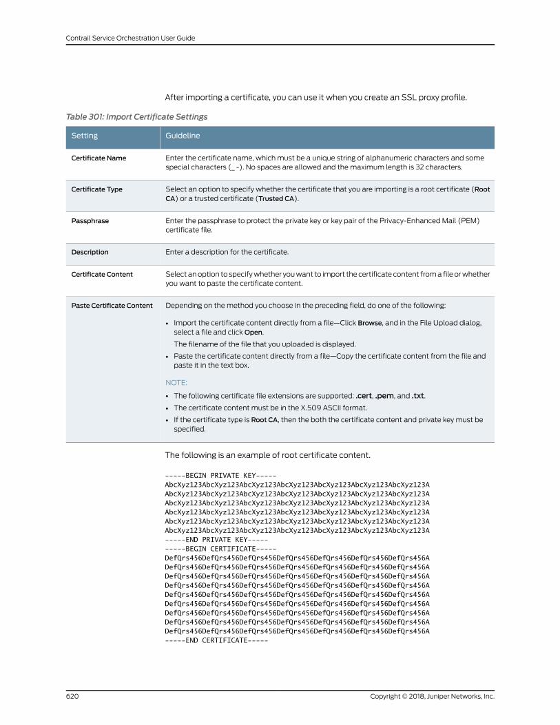
After importing a certificate, you can use it when you create an SSL proxy profile.
Table 301: Import Certificate Settings
GuidelineSetting
Enter the certificate name, which must be a unique string of alphanumeric characters and somespecial characters (_ -). No spaces are allowed and themaximum length is 32 characters.
Certificate Name
Select an option to specify whether the certificate that you are importing is a root certificate (RootCA) or a trusted certificate (Trusted CA).
Certificate Type
Enter the passphrase to protect the private key or key pair of the Privacy-Enhanced Mail (PEM)certificate file.
Passphrase
Enter a description for the certificate.Description
Select anoption to specifywhether youwant to import thecertificate content froma file orwhetheryou want to paste the certificate content.
Certificate Content
Depending on themethod you choose in the preceding field, do one of the following:
• Import the certificate content directly from a file—Click Browse, and in the File Upload dialog,select a file and clickOpen.
The filename of the file that you uploaded is displayed.
• Paste the certificate content directly from a file—Copy the certificate content from the file andpaste it in the text box.
NOTE:
• The following certificate file extensions are supported: .cert, .pem, and .txt.
• The certificate content must be in the X.509 ASCII format.
• If the certificate type is Root CA, then the both the certificate content and private key must bespecified.
Paste Certificate Content
The following is an example of root certificate content.
-----BEGIN PRIVATE KEY-----AbcXyz123AbcXyz123AbcXyz123AbcXyz123AbcXyz123AbcXyz123AbcXyz123AAbcXyz123AbcXyz123AbcXyz123AbcXyz123AbcXyz123AbcXyz123AbcXyz123AAbcXyz123AbcXyz123AbcXyz123AbcXyz123AbcXyz123AbcXyz123AbcXyz123AAbcXyz123AbcXyz123AbcXyz123AbcXyz123AbcXyz123AbcXyz123AbcXyz123AAbcXyz123AbcXyz123AbcXyz123AbcXyz123AbcXyz123AbcXyz123AbcXyz123AAbcXyz123AbcXyz123AbcXyz123AbcXyz123AbcXyz123AbcXyz123AbcXyz123A-----END PRIVATE KEY----------BEGIN CERTIFICATE-----DefQrs456DefQrs456DefQrs456DefQrs456DefQrs456DefQrs456DefQrs456ADefQrs456DefQrs456DefQrs456DefQrs456DefQrs456DefQrs456DefQrs456ADefQrs456DefQrs456DefQrs456DefQrs456DefQrs456DefQrs456DefQrs456ADefQrs456DefQrs456DefQrs456DefQrs456DefQrs456DefQrs456DefQrs456ADefQrs456DefQrs456DefQrs456DefQrs456DefQrs456DefQrs456DefQrs456ADefQrs456DefQrs456DefQrs456DefQrs456DefQrs456DefQrs456DefQrs456ADefQrs456DefQrs456DefQrs456DefQrs456DefQrs456DefQrs456DefQrs456ADefQrs456DefQrs456DefQrs456DefQrs456DefQrs456DefQrs456DefQrs456ADefQrs456DefQrs456DefQrs456DefQrs456DefQrs456DefQrs456DefQrs456A-----END CERTIFICATE-----
Copyright © 2018, Juniper Networks, Inc.620
Contrail Service Orchestration User Guide
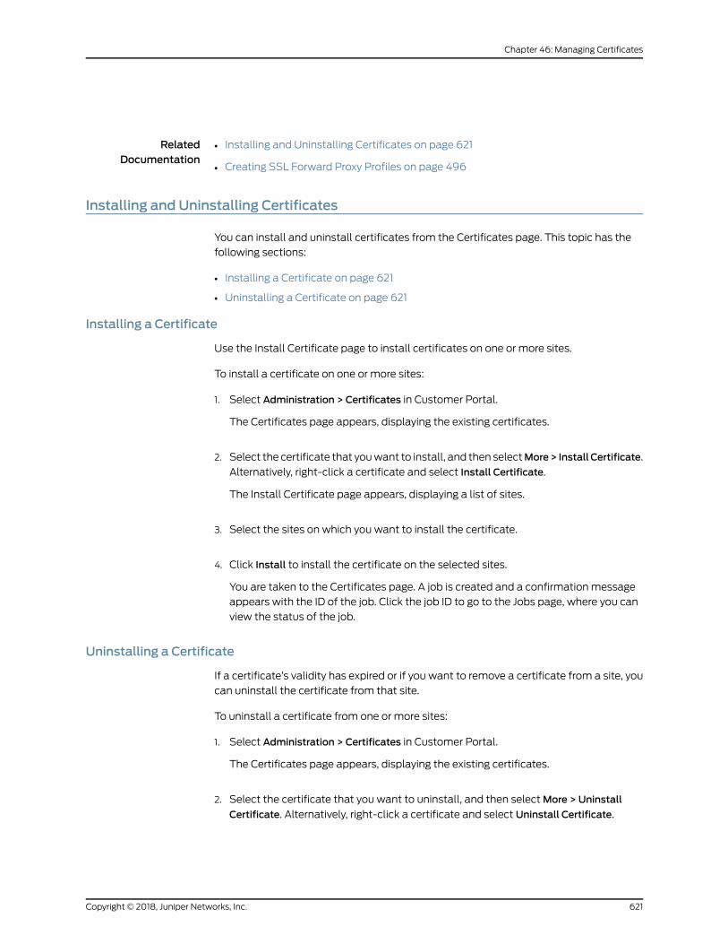
RelatedDocumentation
Installing and Uninstalling Certificates on page 621•
• Creating SSL Forward Proxy Profiles on page 496
Installing and Uninstalling Certificates
You can install and uninstall certificates from the Certificates page. This topic has the
following sections:
• Installing a Certificate on page 621
• Uninstalling a Certificate on page 621
Installing a Certificate
Use the Install Certificate page to install certificates on one or more sites.
To install a certificate on one or more sites:
1. Select Administration > Certificates in Customer Portal.
The Certificates page appears, displaying the existing certificates.
2. Select the certificate that youwant to install, and then selectMore> InstallCertificate.
Alternatively, right-click a certificate and select Install Certificate.
The Install Certificate page appears, displaying a list of sites.
3. Select the sites on which you want to install the certificate.
4. Click Install to install the certificate on the selected sites.
You are taken to the Certificates page. A job is created and a confirmation message
appears with the ID of the job. Click the job ID to go to the Jobs page, where you can
view the status of the job.
Uninstalling a Certificate
If a certificate’s validity has expired or if you want to remove a certificate from a site, you
can uninstall the certificate from that site.
To uninstall a certificate from one or more sites:
1. Select Administration > Certificates in Customer Portal.
The Certificates page appears, displaying the existing certificates.
2. Select the certificate that you want to uninstall, and then selectMore > Uninstall
Certificate. Alternatively, right-click a certificate and select Uninstall Certificate.
621Copyright © 2018, Juniper Networks, Inc.
Chapter 46: Managing Certificates
The Uninstall Certificate page appears, displaying only those sites on which the
certificate was previously installed.
3. Select the sites fromwhich you want to uninstall the certificate.
4. Click Uninstall to uninstall the certificate from the site.
You are taken to the Certificates page. A job is created and a confirmation message
appears with the ID of the job. Click the job ID to go to the Jobs page, where you can
view the status of the job.
RelatedDocumentation
• Importing a Certificate on page 619
Copyright © 2018, Juniper Networks, Inc.622
Contrail Service Orchestration User Guide
CHAPTER 47
Managing Juniper Identity ManagementService
• Juniper Identity Management Service Overview on page 623
• About the Identity Management Page on page 625
• Configuring CSO and JIMS Connection on page 626
• Configuring JIMS for an SRX Device on page 628
Juniper Identity Management Service Overview
Juniper Identity Management Service (JIMS) provides a robust and scalable user
identification and IP address mapping implementation that includes endpoint context
andmachine ID. JIMS collects user identity information from different authentication
sources, for SRX Series devices.
JIMS collects user identity information from a configured Active Directory andmakes it
available to SRX Series devices or vSRX instances. You can download and install Juniper
Identity Management Service (JIMS), configure the CSO client on JIMS to obtain user
identity information from the configured Active Directory, and use CSO and JIMS to
manage user-based firewall policy intents on SRX Series devices and vSRX instances.
The SRX Series devices communicate with JIMS through HTTP or HTTPS connection.
Use HTTP connection for debugging and HTTPS for deployments. SRX Series devices
consist of primary and secondary JIMS configurations. These devicesmust always query
the primary JIMS. The secondary JIMS is available as a fall back option with limited
resources. The secondary JIMSmust be used when the HTTP GET query or a number of
queries to the primary JIMS fails. SRX Series devices constantly scrutinize the failed
primary JIMS and revert to the primary JIMS, once it is up and running.
When you request a JIMS report, the SRX Series device specifies the timestamp. JIMS
formsanHTTPS response fromtheearliest known report since the requested timestamp.
SRXSeriesdevices request for themaximumnumberof reports to include in the response
from JIMS. Along with the requested reports, JIMS always returns a cookie. In the
subsequent requests to JIMs, SRX Series devices include cookies instead of timestamp
to indicate the same context, same beginning timestamp, and to resume the same
response fromwhere it has stopped the previous time.
623Copyright © 2018, Juniper Networks, Inc.
NOTE:
• IP and usermapping informationmight be inaccurate, if the user identitiesin JIMS are cleared, delayed, or missing.
• SRX firewall authentication can also push the authentication entries toJIMS.
The SRX Series device communicates with JIMS through HTTP or HTTPSmessages to
obtain theaccess tokenandquery foruser identities.The followingdifferentquerymodes
are available and all queries can happen simultaneously.
• Access Token Query on page 624
• Batch or Periodic Query on page 624
• IP Address Query on page 624
• User Mapping Query on page 625
Access Token Query
JIMS requires OAuth 2.0 protocol to authenticate or authorize. The SRX Series device
user query function requires an access token to query the JIMS server. The SRX Series
device uses the client credentials such as client ID and client secret to obtain an access
token. These parameters must be consistent with the API client configured on JIMS.
Batch or Periodic Query
At thebeginning, SRXSeriesdevice sends thebatchqueries to JIMSsequentially toobtain
all theexpecteduser identities.When therearenomoreentries in JIMS,SRXSeriesdevice
periodically queries for the newly generated reports with the configured interval.
The timestamp is mentioned in the query to restart the response. The timestamp is
expected in the query under the following circumstances:
• SRX Series device queries the JIMS server for the first time
• SRX Series device switches over to the secondary JIMS
• SRXSeries devicedoes the error recovery becauseof an internal error or upon receiving
error response from JIMS
For all the other cases, SRX Series device provides the received cookie information in the
query instead of a timestamp.
IP Address Query
SRX Series device can provide another query to JIMS specifying the IP address, if it has
missed the data for the existing IP address flow. If there are many IP address queries in
the queue, SRXSeries device can keepmultiple concurrent HTTP or HTTPS connections
with JIMS to increase the throughput. However, the number of concurrent connections
are restricted to less than or equal to 20 connections to reduce the load on JIMS.
Copyright © 2018, Juniper Networks, Inc.624
Contrail Service Orchestration User Guide
User Mapping Query
SRX Series device can engage Captive Portal to obtain the user ID to authenticate the
user. Once the user is authenticated, SRX Series device can issue another query to JIMS
specifying the user ID and IP address to obtain user information. The firewall
authentication uses the
https://<JIMS>/<query-api>/user/ip=<ip>&id=<id>&domain=<domain> API to push an
authentication success entry to JIMS with the user IP, user ID, and the domain. JIMS
responds with the user information.
The difference between the IP address query and user query is that the IP address query
does not have the user ID. Both these queries insert the user information to the internal
cache of JIMS , and all SRX devices are updated with user information.
RelatedDocumentation
About the Identity Management Page on page 625•
• Configuring CSO and JIMS Connection on page 626
• Configuring JIMS for an SRX Device on page 628
About the Identity Management Page
To access this page, select Administration > Identity Management.
NOTE:
• For information on system requirements for installing JIMS, see System
Requirements for Installing Juniper Identity Management Service
• For information on installing JIMS on yourWindows server, see Installing
Juniper Identity Management Service.
Use the Identity Management page to download and install JIMS, interface JIMS with
CSO to obtain advanced user identity an active directory, and use CSO to push the JIMS
configuration to SRX Series devices.
Figure 9 on page 626 illustrates the connectivity between, CSO, JIMS, and an SRX Series
device.
625Copyright © 2018, Juniper Networks, Inc.
Chapter 47: Managing Juniper Identity Management Service
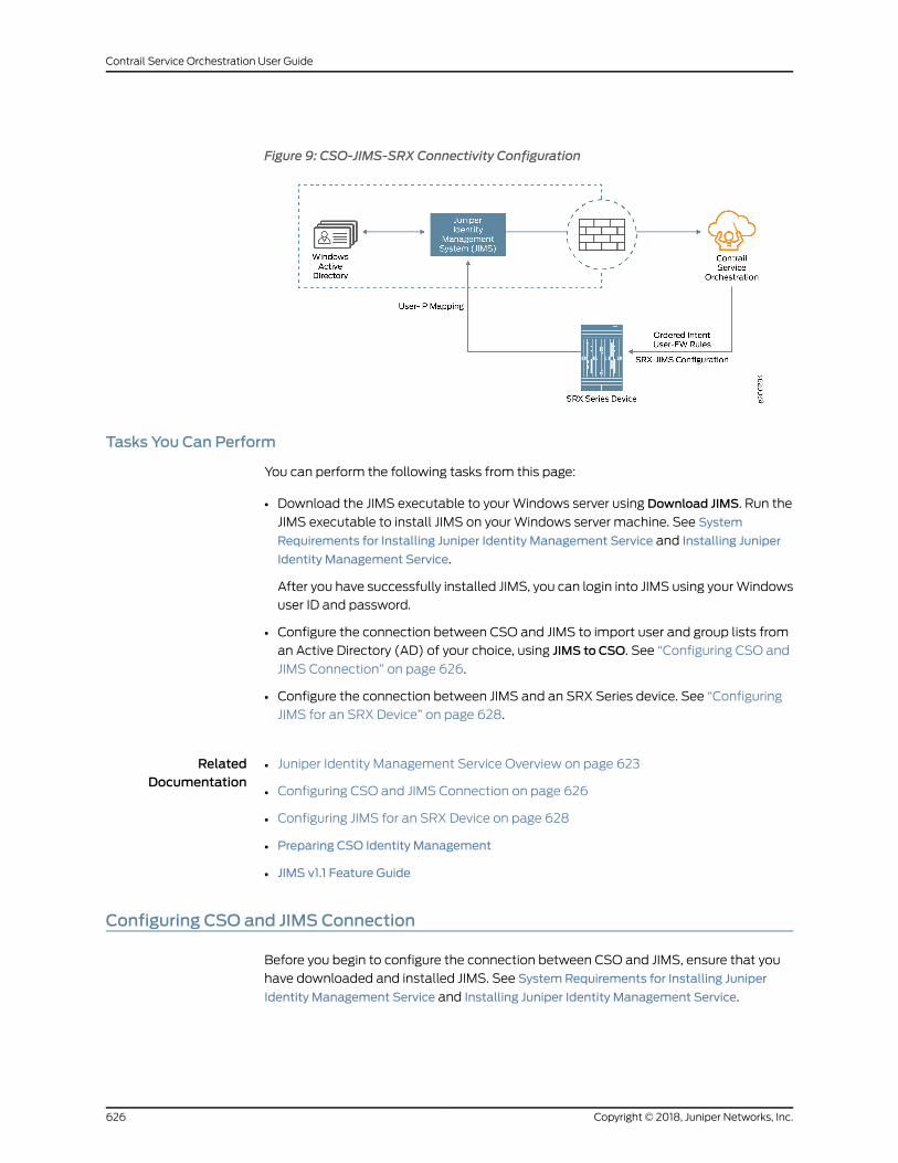
Figure 9: CSO-JIMS-SRX Connectivity Configuration
Tasks You Can Perform
You can perform the following tasks from this page:
• Download the JIMS executable to your Windows server using Download JIMS. Run the
JIMS executable to install JIMS on yourWindows server machine. See System
Requirements for Installing Juniper Identity Management Service and Installing Juniper
Identity Management Service.
After you have successfully installed JIMS, you can login into JIMS using yourWindows
user ID and password.
• Configure the connection between CSO and JIMS to import user and group lists from
an Active Directory (AD) of your choice, using JIMS to CSO. See “Configuring CSO and
JIMS Connection” on page 626.
• Configure the connection between JIMS and an SRX Series device. See “Configuring
JIMS for an SRX Device” on page 628.
RelatedDocumentation
Juniper Identity Management Service Overview on page 623•
• Configuring CSO and JIMS Connection on page 626
• Configuring JIMS for an SRX Device on page 628
• Preparing CSO Identity Management
• JIMS v1.1 Feature Guide
Configuring CSO and JIMS Connection
Before you begin to configure the connection between CSO and JIMS, ensure that you
have downloaded and installed JIMS. See System Requirements for Installing Juniper
Identity Management Service and Installing Juniper Identity Management Service.
Copyright © 2018, Juniper Networks, Inc.626
Contrail Service Orchestration User Guide
To configure a connection between CSO and JIMS:
1. Select Administration > Identity Management.
The Identity Management page appears.
2. Click JIMS-to-CSO Configuration or the greater-than (>) symbol beside it.
The JIMS-to-CSOConfigurationpanel expands.Thepaneldisplaysasystem-generated
user name which cannot be changed, the last updated time of the user identity
information from Active Directory and the connection status of the JIMS server(s).
NOTE: If you have already configured a JIMS user account in CSO, thedetails of this connection is displayed in the JIMS-to-CSO Configuration
panel.
3. The Username is auto-generated for each tenant. You will not be able to change it.
Enter a password of your choice for your JIMS-to-CSO connection in the Password
field.
NOTE: The passwordmust contain a number, an upper-case letter, anda special character.
NOTE: The password you entered will appear encrypted. If you want tosee the password that you entered as plain text, select ShowPassword.
4. Click Save to save your changes. The JIMS user credentials are saved.
If you do not want to save your changes, click Cancel.
5. CSO and JIMS need to be connected in order for JIMS to push data to CSO. To set up
this connection, youmust configure the CSO client on JIMS, using the username and
password that you created in the JIMS-to-CSO Configuration panel. For more
information on configuring the CSO client on JIMS, see Configuring the Connection to
a CSO Client.
6. Configure an Active Directory (AD) as a data source in JIMS, see Configuring the
Connection to an Active Directory.
627Copyright © 2018, Juniper Networks, Inc.
Chapter 47: Managing Juniper Identity Management Service
NOTE: After your JIMSuser credentialsaresaved, thepassword fieldchangesto the Change Password link.
If you want to change your password, click Change Password.
The Change Password page appears.
• Enter your new password in theNewPassword field and re-enter the same
password in the Confirm Password field.
• ClickOK to save the new password. The updated password is saved.
If you do not want to save your new password, click Cancel instead.
RelatedDocumentation
Juniper Identity Management Service Overview on page 623•
• About the Identity Management Page on page 625
• Configuring JIMS for an SRX Device on page 628
Configuring JIMS for an SRX Device
Configuring the connection between SRX Series devices to JIMS allows the JIMS server
to send the IP address, username, and group relationship information to SRX Series
devices through CSO. You can also configure a set of optional advanced settings for
authentication timeout, domain filters, and choose to include or exclude user identity
information in the communication between the JIMS server and the SRX Series device.
For every SRX Series device, you can configure the primary and secondary JIMS servers.
TheSRXSeries device always queries theprimary JIMS server. The secondary JIMS server
is available as a fallback optionwith limited resources. The secondary JIMS server is used
when a number of queries to the primary JIMS server fails. The SRX Series device
constantly scrutinizes the failed primary JIMS server and reverts to the primary JIMS
server, once it is up and running.
Before you begin, you need the following information:
• The IP address of the primary and secondary (optional) JIMS server.
• The Certificate Authority (CA) certificate for the primary and secondary (optional)
JIMS server.
• The client ID to obtain an OAuth token from the JIMS server for user queries.
• The client secret to obtain an OAuth token from the JIMS server for user queries.
Copyright © 2018, Juniper Networks, Inc.628
Contrail Service Orchestration User Guide
To configure a connection between an SRX Series device and JIMS:
1. Select Administration > Identity Management.
The Identity Management page appears.
2. Click SRX-to-JIMS Configuration or the greater-than (>) symbol beside it.
The SRX-to-JIMS Configuration panel expands.
NOTE: If you have already configured JIMS for an SRX Series device, thedetails of this configuration is displayed in the SRX-to-JIMS Configuration
panel.
3. Complete the configuration according to the guidelines provided in
Table 302 on page 629.
4. Click Save to save the changes. JIMS is now configured for an SRX device.
If you want to discard your changes, click Cancel instead.
Table 302 on page 629 provides guidelines on using the fields on the SRX-to-JIMS
Configuration panel.
Table 302: Fields on the SRX-to-JIMS Configuration Panel
DescriptionField
Identity
Enter a valid IPv4 or IPv6 address of the primary JIMS server.
SRX Series devices always query the primary JIMS to obtain the user identities.
IP Address
Enable this option to use the secondary JIMS server as a fallbackwhen the primary JIMS serverfails. By default, this option is disabled.
Secondary Identity
Enter a valid IPv4 or IPv6 address of the secondary JIMS server.
The secondary JIMS is available as a fall back optionwith limited resources. Use the secondaryJIMS when the HTTP GET query or number of queries to the primary JIMS fails.
Secondary IP Address
Client Credentials
Enter theclient ID that theSRXSeriesdeviceprovides to JIMSserveraspartof itsauthentication.The SRX Series devicemust authenticate itself with the JIMS server to obtain an access tokenthat allows the it to query the JIMS server for user identity information. The client ID must beconsistent with the CSO client ID or username configured on the JIMS server.
Client ID
Enter the client secret that the SRX Series device provides to the JIMS server as part of itsauthentication. The client secret must be consistent with the CSO client secret or passwordconfigured on the JIMS server.
Client Secret
629Copyright © 2018, Juniper Networks, Inc.
Chapter 47: Managing Juniper Identity Management Service
Table 302: Fields on the SRX-to-JIMS Configuration Panel (continued)
DescriptionField
Advanced Settings
Enter the timeout interval (in minutes) after which, the idle entries in the JIMS authenticationtable expire. The timeout interval begins fromwhen the user authentication entry is added tothe authentication table. This value can be between 10 and 1440minutes, where a value of 0means no timeout. The default value is 69minutes.
Authentication Entry Timeout
The SRX Series device sends a query to JIMS for the user identity information only for the IPaddressespresent in theselectedaddressgroup; JIMS respondswith the requesteduser identityinformation.
Click Add NewAddress to create a new IP address group, see “Creating Addresses or AddressGroups” on page 507.
Include IP Address(es)
The SRX Series device does not query JIMS for the user identity information for the excludedIP addresses present in the selected address group.
Click Add NewAddress to create a new IP address group, see “Creating Addresses or AddressGroups” on page 507.
Exclude IP Address(es)
TheSRXSeriesdevicesendsaquery to JIMSfor theuser identity informationwithin thespecifieddomains. Enter a comma-separated list of up to 25 domain names. A domain name can bean alphanumeric string of up to 64 characters that can also contain dashes, underscores, anddots.
Example: example.net
Filter Domain(s)
RelatedDocumentation
• Juniper Identity Management Service Overview on page 623
• About the Identity Management Page on page 625
• Configuring CSO and JIMS Connection on page 626
Copyright © 2018, Juniper Networks, Inc.630
Contrail Service Orchestration User Guide
PART 3
Designer Tools
• Configuration Designer on page 633
• Resource Designer on page 651
• Network Service Designer introduction on page 671
• Creating Requests for Network Services on page 673
• Creating Network Services on page 681
• Managing Network Services on page 703
631Copyright © 2018, Juniper Networks, Inc.

Copyright © 2018, Juniper Networks, Inc.632
Contrail Service Orchestration User Guide
CHAPTER 48
Configuration Designer
• Configuration Designer Overview on page 633
• Accessing the Configuration Designer on page 635
• Using the Configuration Designer on page 635
• Changing Your Password on page 636
• About the Requests Page for the Configuration Designer on page 637
• Creating Requests for Configuration Templates on page 638
• Designing Templates with a YANG Configuration on page 639
• Designing Templates with a Configuration on page 642
• Publishing Configuration Templates on page 646
• About the Designs Page for the Configuration Designer on page 647
• Cloning Configuration Templates on page 649
• Deleting Configuration Template Designs on page 649
Configuration Designer Overview
Configuration Designer, Resource Designer, and Network Service Designer are visual
designer tools used by the Juniper Networks Cloud CPE solution for smooth onboarding.
The tools offer network designers a convenient way of bringing virtualized network
functions (VNFs) from Juniper Networks and third-party companies into the network
services catalog using a graphical user interface (GUI).
ConfigurationDesignerprovidesan intuitiveUI-basedworkflowfor creatingandmanaging
configuration templates. These templates are rendered automatically in a GUI format
that can be used as is by Resource Designer. Resource Designer uses these templates
to create VNF packages that are then published to Network Service Designer.
NetworkServiceDesigner uses theVNFpackages to design customizednetwork services
thatarepublished to thenetwork servicescatalog.Thenetwork servicescatalogcontains
a list of usable network services. Service provider administrators access the network
services catalog to assign a set of network services to their customers using the
Administration Portal. Finally, customer administrators access the network services
assigned to them using a Customer Portal to manage their sites and services.
Figure 10 on page 634 shows a Configuration Designer and its workflow.
633Copyright © 2018, Juniper Networks, Inc.
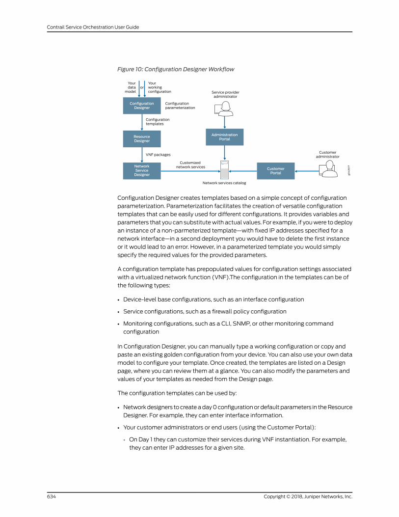
Figure 10: Configuration DesignerWorkflow
g043577
Customeradministrator
Service provideradministrator
Yourdata
modelor
Yourworkingconfiguration
CustomerPortal
AdministrationPortal
NetworkServiceDesigner
Network services catalog
ResourceDesigner
ConfigurationDesigner
Configurationparameterization
VNF packages
Customizednetwork services
Configurationtemplates
Configuration Designer creates templates based on a simple concept of configuration
parameterization. Parameterization facilitates the creation of versatile configuration
templates that can be easily used for different configurations. It provides variables and
parameters that you can substitutewith actual values. For example, if youwere todeploy
an instance of a non-parmeterized template—with fixed IP addresses specified for a
network interface—in a second deployment you would have to delete the first instance
or it would lead to an error. However, in a parameterized template you would simply
specify the required values for the provided parameters.
A configuration template has prepopulated values for configuration settings associated
with a virtualized network function (VNF).The configuration in the templates can be of
the following types:
• Device-level base configurations, such as an interface configuration
• Service configurations, such as a firewall policy configuration
• Monitoring configurations, such as a CLI, SNMP, or other monitoring command
configuration
In Configuration Designer, you canmanually type a working configuration or copy and
paste an existing golden configuration from your device. You can also use your own data
model to configure your template. Once created, the templates are listed on a Design
page, where you can review them at a glance. You can also modify the parameters and
values of your templates as needed from the Design page.
The configuration templates can be used by:
• Networkdesigners tocreateaday0configurationordefault parameters in theResource
Designer. For example, they can enter interface information.
• Your customer administrators or end users (using the Customer Portal):
• On Day 1 they can customize their services during VNF instantiation. For example,
they can enter IP addresses for a given site.
Copyright © 2018, Juniper Networks, Inc.634
Contrail Service Orchestration User Guide
• On Day 2 they can update a configuration of existing instances. For example, they
can configure their network to block social media.
RelatedDocumentation
Accessing the Configuration Designer on page 635•
• Changing Your Password on page 636
• Using the Configuration Designer on page 635
Accessing the Configuration Designer
To access the Configuration Designer:
1. Review the OpenStack keystone username and password that you defined.
• For a centralized deployment, you can view these settings on the Contrail configure
and control node in the files /etc/contrail/keystonerc and /etc/contrail/openstackrc.
• For a distributed deployment, you can view these settings on the central
infrastructure node in the file /etc/keystone/keystonerc.
• The default username is cspadmin and the default password is passw0rd.
2. Using aWeb browser, access the URL for the Configuration Designer.
For example, if the IP address of the host onwhich the Configuration Designer resides
is 192.0.2.1, the URL would be https://192.0.2.1:83/cd-ui/index.html.
3. Log in with the OpenStack Keystone username and password.
RelatedDocumentation
Configuration Designer Overview on page 633•
Using the Configuration Designer
Use the Configuration Designer to create a configuration template or modify an existing
one. Follow these steps to get started with the Configuration Designer:
• Learn about the Configuration Designer. See “Configuration Designer Overview” on
page 633.
• Log into the Configuration Designer. See “Accessing the Configuration Designer” on
page 635.
To create a configuration template:
1. Createa request for aconfiguration template.See “CreatingRequests forConfiguration
Templates” on page 638.
2. Design a configuration template. You can design a configuration template using one
of these methods:
635Copyright © 2018, Juniper Networks, Inc.
Chapter 48: Configuration Designer
• Using a data model. Choose this method when you already have a data model for
your configuration template. See “Designing Templateswith aYANGConfiguration”
on page 639.
• Using your working configuration. Choose this method when you have a Jinja
template but want the Configuration Designer to generate a data model for your
configuration template.See “DesigningTemplateswithaConfiguration”onpage642.
3. Publish the configuration template to the Network Service Designer. See “Publishing
Configuration Templates” on page 646.
RelatedDocumentation
Configuration Designer Overview on page 633.•
Changing Your Password
Someof the Contrail ServiceOrchestration components—such as Administration Portal,
Configuration Designer, Resource Designer, and Network Service Designer—have a
common password. When you change the password from any of these GUIs, the new
password is saved in Contrail and applies to all the GUIs.
To change your password:
1. Click the administrative username located at the right side of the top banner.
A drop-down list appears.
2. Click Change Password.
The Change Password page appears.
3. Change your password following the guidelines provided in Table 303 on page 636.
4. ClickOK.
You are logged out of the system. To log in to the GUI again, youmust use your new
password. Other sessions logged in with the same username are unaffected until the
next login.
Table 303: Fields on the Changing Password Page
DescriptionField
Enter your existing password.Current Password
Copyright © 2018, Juniper Networks, Inc.636
Contrail Service Orchestration User Guide
Table 303: Fields on the Changing Password Page (continued)
DescriptionField
Enter your new password.
Theminimum character length for this field is 6 (the default) and themaximum is 21. Thepassword can include alphanumeric and special characters, but not control characters. Thepassword strength indicator displays the efficiency of the password that you entered.
NOTE: You cannot proceed to the next step if the password strength indicator shows that thepassword is weak.
New Password
Reenter the password for confirmation.
You can select the ShowPassword option to view the password.
Confirm Password
RelatedDocumentation
Administration Portal Overview on page 4•
• Configuration Designer Overview on page 633
• Resource Designer Overview on page 651
• Network Service Designer Overview on page 671
About the Requests Page for the Configuration Designer
To access this page, click Home> Requests.
You can use the Requests page to request a new configuration template. A configuration
templatehasprepopulatedvalues for configuration settingsassociatedwitha virtualized
network function (VNF). By using a configuration template for a network service, you can
avoid having to manually configure settings for each service.
Tasks You Can Perform
You can perform the following tasks from this page:
• Createa request for aconfiguration template.See “CreatingRequests forConfiguration
Templates” on page 638.
• Design a new configuration template using a predefined working configuration. In this
method, the Configuration Designer generates the data model. See “Designing
Templates with a Configuration” on page 642.
• Designanewconfiguration templateusing theYANGmodel.See “DesigningTemplates
with a YANG Configuration” on page 639.
Field Descriptions
Table 304 on page 638 provides guidelines on using the fields on the Requests page for
the Configuration Designer.
637Copyright © 2018, Juniper Networks, Inc.
Chapter 48: Configuration Designer
Table 304: Fields on the Requests Page for the Configuration Designer
DescriptionField
Requests Page
Click to request a new configuration template.
The New Template page allows you to define the requirements for your configurationtemplate.
New Template
Configuration Template Request
Click to design a new configuration template using a predefined working configuration.
Select thismethod if youhave the Jinja2configurationbutneed theConfigurationDesignerto generate a data model for your configuration template.
Begin with config
Click to design a configuration template using an existing data model.
Select this method if you already have the Jinja2 (a template engine for Python)configuration and the data model for your configuration template.
Begin with YANG
Click to delete a configuration template request.Delete
RelatedDocumentation
Configuration Designer Overview on page 633•
• Using the Configuration Designer on page 635
Creating Requests for Configuration Templates
You can create a configuration template by first making a request for it. A request allows
you to define the requirements for the configuration template, including the template
format, vendor, and the supported device family.
To create a request for a configuration template:
1. Click Home > Requests > New Template.
2. Complete the configuration according to the guidelines provided in
Table 305 on page 639.
3. Click Create.
A new template request is created.
Copyright © 2018, Juniper Networks, Inc.638
Contrail Service Orchestration User Guide
Table 305: Fields on the New Template Page
DescriptionField
Specify a name for your configuration template. Only a string of alphanumeric characters, dashes, andspaces are accepted.
Example: ucpe-SRX DPI config
Name
Enter adescription for your configuration template.Make this descriptionas clear anduseful aspossiblefor all administrators.
Example: NFX JCP configuration to restore default route fromLAN toWAN. This configuration is pushedto JCP after the service chain is deleted.
Description
Select a format for your configuration template:
• CLI (Command-line interface)
• XML (Extensible Markup Language)
• Native—Default file format of the application thatwe use to create and save files.We use CLI plug-inand it is used for cms_plug-in.
Output config format
Specify the category for the configuration template. Categories allow you to group your templates andfilter and search them easily.
• VNF—Select thisoptionwhenyoucreateaconfiguration template for thevirtualizednetwork function.
• Device Template—Select this option when you create a device template for a network device, suchas a customer premises equipment (CPE) device.
• Other—Select this option when you create a configuration template for a network function otherthan VNF or device template.
Category
Specify the vendor that you want the configuration template to support.
Example: Juniper Networks
Vendor
Specify the device family that you want the configuration template to support.
Example: juniper-srx
Device family
RelatedDocumentation
Configuration Designer Overview on page 633•
• Designing Templates with a YANG Configuration on page 639
• Designing Templates with a Configuration on page 642
Designing Templates with a YANGConfiguration
You can design a configuration template either by using your own YANGmodel or by
using the YANGmodel generated by the Configuration Designer. The Configuration
Designer provides a wizard that takes you through a step-by-step procedure to create a
configuration template. You can design multiple templates by creating requests and
launching respective wizards from them.
639Copyright © 2018, Juniper Networks, Inc.
Chapter 48: Configuration Designer
To design a template using your own data model, make sure to have your data model
schema and Jinja (a template engine for Python) template content ready.
Before you begin, create a configuration template request. See “Creating Requests for
Configuration Templates” on page 638.
To design a configuration template with your own YANGmodel:
1. From the Configuration Template Request drop-down list, select Begin with YANG.
The Enter YANG Schema page appears.
2. Enter or copy and paste your YANG schema in the space provided for it. Click Next.
The Enter Jinja Template page is displayed.
3. Enter or copy and paste your Jinja template content in the space provided for it. Click
Next.
NOTE: You can also download a sample template from this page.
NOTE: When you paste the Jinja template, the Configuration Designerdetects thekeywordspost_config,pre_config, anddiff_configautomatically.
If the configuration template contains any one of these three keywords,the template will enable the Diff Config feature.
4. Click Next.
The Generate UI page appears and generates a UI page based on your YANG schema
and displays a read-only view. The fields on this pagemap to the parameters in the
configuration template. You can drag and drop the field labels to reorder the UI.
NOTE: If you edit an existing template and change its datamodel, thenyou can generate a newUI for it by clicking Re-generate ui. If you do not
want a newUI, skip to the next step.
5. Click Next.
The Validate Template page appears.
6. Enter values that you want to validate. See Table 306 on page 641 for sample fields
and their descriptions. Click Validate.
A configuration template is generated using the values that you entered.
Copyright © 2018, Juniper Networks, Inc.640
Contrail Service Orchestration User Guide
7. In the Validate Template page, make sure your data in the template is complete and
correct.
8. Click Yes, it looks good to close the page. If any parameter value in the configuration
template needs tobe changed, clickNo, it needschange to return to thepreviouspage.
9. Click Next.
The Review Template page is displayed. It contains three tabs—Jinja Template, Data
Model, and View Def. You can click through the tabs to view and update your Jinja
template, data model, and view definition.
10. Click Done to save your configuration template.
The Designs page is updated with the new configuration template and its status shows
as Validated. You canmonitor andmanage the new configuration template from the
Configuration Design page.
NOTE: You need to publish the configuration template for it to be availablefor the Resource Designer to create virtualized network function (VNF)packages. See “Publishing Configuration Templates” on page 646.
Table 306: Sample Fields on the Validate Template Page
DescriptionField
Specify the fully qualified domain names (FQDNs) or IP addresses of one or more DNS nameservers.
Example: 10.0.2.15
Name Servers
Specify the FQDNs or IP addresses of one or more NTP servers.
Example: ntp.example.net
NTP Servers
Specify the time zone for your virtual machine.
Example: UTC
Time Zone
For a centralized deployment, select True to enable the default screens security profile for thedestination zone or False to disable default screening.
Example: False
NOTE: You cannot configure this setting for a distributed deployment.
Enable Default Screens
Select True to enable a stateless firewall filter that protects the Routing Engine fromdenial-of-service (DoS) attacks or False to allow DoS attacks.
Example: True
Enable Re-filter
641Copyright © 2018, Juniper Networks, Inc.
Chapter 48: Configuration Designer
Table 306: Sample Fields on the Validate Template Page (continued)
DescriptionField
Specify an IPv4or IPv6 loopbackaddress for themanagement interfaceof your virtualmachine.
Example: 192.0.2.25
Loopback Addr
For a centralized deployment, specify the hostname of your virtual machine that contains thevSRXVNF.Thehostnamehasno limit on thenumberof charactersandaccepts letters, numbers,and symbols.
Example: vm-vsrx
NOTE: For a distributed deployment, the vSRX application resides on the NFX250 device, andyou cannot configure this setting.
Hostname
Specify the FQDNs or IP addresses of one or more system log servers.
Example: 192.0.2.55
Syslog Servers
Specify the identifier of the interface receiving data transmitted by the host.
Example: GigabitEthernet3
Right Interface
Specify the identifier of the interface that transmits data to the host.
Example: GigabitEthernet2
Left Interface
Allowed Prefix List
If you set the Enable Re-filter field to True, specify the routes that the Junos Space VirtualAppliance uses for ping operations when it discovers the vSRX VNF.
Example: 10.0.2.1/24
Ping Prefix List
If you set the Enable Re-filter field to True, specify the routes that the Junos Space VirtualAppliance uses for SNMP operations when it discovers the vSRX VNF.
Example: 10.0.2.0/24
SNMP Prefix list
If you set the Enable Re-filter field to True, specify the IP addresses of the virtual machines thatcontain the Junos Space Virtual Appliances.
Example: 10.0.2.50
Space Servers
RelatedDocumentation
Configuration Designer Overview on page 633•
• Designing Templates with a Configuration on page 642
Designing Templates with a Configuration
You can design a configuration template either by using your own datamodel or by using
the data model generated by the Configuration Designer. The Configuration Designer
providesaconfiguration templatewizard that takesyou throughastep-by-stepprocedure
Copyright © 2018, Juniper Networks, Inc.642
Contrail Service Orchestration User Guide
to create your configuration template. You can design multiple templates by creating
requests and launching respective wizards from them.
To design a template using the datamodel generated by the Configuration Designer, you
provide your Jinja configuration and the wizard automatically parses its parameters and
generates the data model for your template. See
http://jinja.pocoo.org/docs/2.10/templates/ for documenting the configuration templates
of the jinja2 Pythonmodule.
Before you begin, create a configuration template request. See “Creating Requests for
Configuration Templates” on page 638.
To design a template with your configuration:
1. From the Configuration Template Request drop-down list, select Begin with config.
The Templatize Config page appears.
2. Enter or copy and paste your Jinja configuration in the space provided for it.
The wizard parses the parameters in your configuration and generates a variables
tree in the Detected Variables panel.
NOTE: You can also download a sample template from this page.
NOTE: When you paste the Jinja template, the Configuration Designerdetects thekeywordspost_config,pre_config, anddiff_config, automatically.
If the configuration template contains any one of these three keywords,the template will enable the Diff Config feature.
3. Review your configuration and edit it as needed. The wizard accordingly updates the
variables in the Detected Variables panel. Click Next.
The Customize Variables page appears.
4. Select any variable to update. You can update different attributes of your template,
such as the Yang and data types. You can also add default values and descriptions.
See Table 307 on page 645 for sample fields and their descriptions.
5. After completing your configuration, click Next.
TheGenerateUI pageappears andgenerates thedatamodel according to your values
and displays as read-only. You can drag and drop the field labels to reorder the UI.
643Copyright © 2018, Juniper Networks, Inc.
Chapter 48: Configuration Designer
NOTE: If you edit an existing template and change its datamodel, thenyou can generate a newUI for it by clicking Re-generate ui. If you do not
want a newUI, skip to the next step.
6. Click Next.
The Validate Template page appears.
7. Enter values that you want to validate, and ensure that the configuration template is
displayed with the correct values.
8. Click Validate.
TheRenderedConfig page appears and the configuration template is generated using
the values that you entered.
9. Make sure your data in the configuration template is complete and correct.
10. Click Yes, it looks good to close the page. If any parameter value in the configuration
template needs tobe changed, clickNo, it needschange to return to thepreviouspage.
11. Click Next.
The Review Template page is displayed. It contains three tabs—Jinja Template, Data
Model, and View Def. You can click through the tabs to view and update your Jinja
template, data model, and the view definition.
12. Click Done to save your configuration template.
The Designs page is updated with the new configuration template and its status shows
as Validated. You canmonitor andmanage the new configuration template from the
Configuration Design page.
NOTE: Youmust publish the configuration template for it to be available fortheResourceDesigner tocreatevirtualizednetwork function(VNF)packages.See “Publishing Configuration Templates” on page 646.
Copyright © 2018, Juniper Networks, Inc.644
Contrail Service Orchestration User Guide
Table 307: Sample Fields on the Customize Variables Page
DescriptionField
Edit the variable name. A configuration template contains variables that getreplaced with values when a template is rendered. The Configuration Designerautomatically generates these variables from your Jinja configuration.
You can edit the variable name.
Example: left_interface
Detected Variables
Select an appropriate Yang type from the drop-down list. A Yangmodule definesa data model through its data, and through the hierarchical organization andconstraints on that data. It uses a hierarchical, tree-based structure with thefollowing nodes:
• leaf node—Contains a single value of a specific type
• leaf-list node—Contains a sequence of leaf nodes
• containernode—Containsagroupingof relatednodescontainingonlychildnodes,which can be any of the six node types
• listnode—Containsa sequenceof list entries, eachofwhich is uniquely identifiedby one or more key leafs
• choice node—Contains a set of alternatives, only one of which may exist at anyone time
• case node—Contains branches of the choice node
Yang Type
Select an appropriate data type based on your variable. In Yang, each leaf andleaf-list node includes the type statement to identify the data type for valid datafor that node. Yang defines a set of built-in types and also provides the typedefstatement fordefiningaderived type fromabase type,whichcanbeeither abuilt-intype or another derived type.
• String—Human-readable string
• Boolean—True or false
• Init8—8-bit signed integer
• Init16—16-bit signed integer
• Init32—32-bit signed integer
• Init64—64-bit signed integer
• Uint8—8-bit unsigned integer
• Uint16—16-bit unsigned integer
• Uint32—32-bit unsigned integer
• Uint64—64-bit unsigned integer
• Enumeration—Enumerated strings with associated numeric values
• Inet: ip-address—192.0.2.101
• Inet: ip-prefix—192.0.2.0/24
• Empty—A leaf that does not have any value
Data Type
Specify the name of the variable as you want it to display.Display Name
Specify the key to be associated with the variable.
Keys are identifiers used in defining list entries in the Yang data hierarchy. Theyhelp distinguish one list entry from another.
Key
645Copyright © 2018, Juniper Networks, Inc.
Chapter 48: Configuration Designer
Table 307: Sample Fields on the Customize Variables Page (continued)
DescriptionField
Specify if the variable is mandatory.Required
Specify the default value for the variable.Default Value
Specify the regular expression (regex pattern) if the data type of the variable isstring.
Example: ^[a-z][A-Z]
Pattern
This field displays values only if the data type of the variable is enumeration.Whenyou select the data type as enumeration, you need to specify the values for theenumeration list and these values are displayed in the Information column. Youcan also edit the enumeration list.
Example: [“abc”,”def”]
Information
Enter a meaningful description for the variable.
Example: Firewall policy information
Description
To create an actual configuration for a device, youmust log in to Administration Portal
or Customer Portal. Youmust enter the actual values for the configuration in the
configuration template. The configuration template then renders the actual values. You
can click on stage2 configuration to view the actual configuration.
To delete an actual configuration for a device, youmust login to Administration Portal
or Customer Portal and execute the delete command, remove command or an alternate
command for the configuration. The command to delete a configuration depends on the
existing configuration on the device.
RelatedDocumentation
Configuration Designer Overview on page 633•
• Designing Templates with a YANG Configuration on page 639
Publishing Configuration Templates
After you have designed a configuration template, you need to publish it. Only published
configuration templates are available to the Resource Designer for creating virtualized
network function (VNF) packages.
Use one of the following methods to design a configuration template:
• Using a datamodel. Choose thismethodwhen you already have a datamodel for your
configuration template. See “Designing Templates with a YANG Configuration” on
page 639.
Copyright © 2018, Juniper Networks, Inc.646
Contrail Service Orchestration User Guide
• Using your working configuration. Choose thismethodwhen you have a Jinja template
but want the Configuration Designer to generate a data model for your configuration
template. See “Designing Templates with a Configuration” on page 642.
To publish a configuration template:
1. Select Home> Designs.
The Configuration Template Designs page appears. All the configuration templates
are displayed in a table.
2. Select the configuration template (with the status as Validated) that you want to
publish to the Resource Designer.
3. Select Publish from the Edit drop-down list.
Your configuration template is published and available to be used by the Resource
Designer. Its status changes from Validated to Published.
RelatedDocumentation
Configuration Designer Overview on page 633•
About the Designs Page for the Configuration Designer
To access this page, click Home> Designs.
Use the Designs page to manage configuration template designs that you have saved
or published.
Tasks You Can Perform
You can perform the following tasks from this page:
• View the configuration template designs. Table 308 on page 648 describes the fields
on the Configuration Template Designs page.
• Modify a configuration template design that you published or saved using the
configuration. Click Edit from the drop-down list at the end of the appropriate row and
make your updates. See “Designing Templates with a Configuration” on page 642.
• Modify a configuration template design that you published or saved using the YANG
model. Click Edit from the drop-down list at the end of the appropriate row andmake
your updates. See “Designing Templates with a YANG Configuration” on page 639.
• Publishaconfiguration template.See“PublishingConfigurationTemplates”onpage646.
• Clone a configuration template. See “Cloning Configuration Templates” on page 649.
• Delete a configuration template. See “Deleting Configuration Template Designs” on
page 649.
647Copyright © 2018, Juniper Networks, Inc.
Chapter 48: Configuration Designer
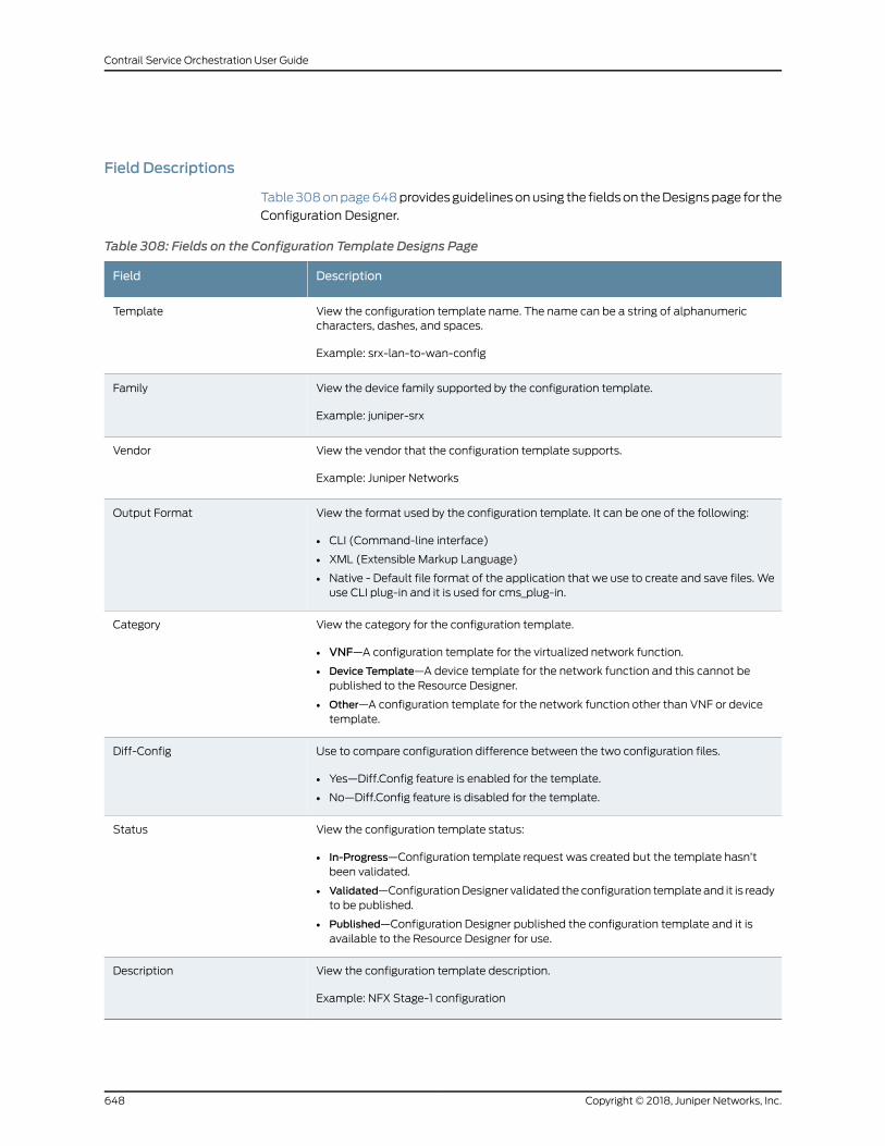
Field Descriptions
Table308onpage648providesguidelinesonusing the fieldson theDesignspage for the
Configuration Designer.
Table 308: Fields on the Configuration Template Designs Page
DescriptionField
View the configuration template name. The name can be a string of alphanumericcharacters, dashes, and spaces.
Example: srx-lan-to-wan-config
Template
View the device family supported by the configuration template.
Example: juniper-srx
Family
View the vendor that the configuration template supports.
Example: Juniper Networks
Vendor
View the format used by the configuration template. It can be one of the following:
• CLI (Command-line interface)
• XML (Extensible Markup Language)
• Native - Default file format of the application that we use to create and save files. Weuse CLI plug-in and it is used for cms_plug-in.
Output Format
View the category for the configuration template.
• VNF—A configuration template for the virtualized network function.
• Device Template—A device template for the network function and this cannot bepublished to the Resource Designer.
• Other—A configuration template for the network function other than VNF or devicetemplate.
Category
Use to compare configuration difference between the two configuration files.
• Yes—Diff.Config feature is enabled for the template.
• No—Diff.Config feature is disabled for the template.
Diff-Config
View the configuration template status:
• In-Progress—Configuration template request was created but the template hasn’tbeen validated.
• Validated—ConfigurationDesigner validated the configuration template and it is readyto be published.
• Published—Configuration Designer published the configuration template and it isavailable to the Resource Designer for use.
Status
View the configuration template description.
Example: NFX Stage-1 configuration
Description
Copyright © 2018, Juniper Networks, Inc.648
Contrail Service Orchestration User Guide
RelatedDocumentation
Configuration Designer Overview on page 633•
• About the Requests Page for the Configuration Designer on page 637
Cloning Configuration Templates
Cloning a template is useful when you want to create a configuration template that is
similar to an existing one but with small differences. You can easily clone an existing
template from the Designs page and customize it as needed.
To clone a configuration template design:
1. Select Home>Designs.
The Designs page appears.
2. Select the configuration template design that you want to clone, and click the clone
icon at the top of the Designs page.
The Clone Template page appears.
3. Specify an appropriate name for your new configuration template. For example,
uCPE-SRX NAT config.
4. Click Save.
A message is displayed indicating that the template was cloned successfully. The
cloned configuration template appears on the Designs page.
If you want to edit the cloned configuration template, select the template and click Edit
from the drop-down list at the end of the row.
RelatedDocumentation
About the Designs Page for the Configuration Designer on page 647•
• Designing Templates with a Configuration on page 642
• Designing Templates with a YANG Configuration on page 639
Deleting Configuration Template Designs
You can easily delete a configuration template design from the Designs page.
To delete a configuration template design:
1. Select Home>Designs.
The Designs page appears.
2. Select the configuration template design that you want to delete.
649Copyright © 2018, Juniper Networks, Inc.
Chapter 48: Configuration Designer
3. Click Delete from the drop-down list at the end of the row.
A page requesting confirmation for the deletion appears.
4. Click Yes to confirm that you want to delete the design.
The configuration template design is deleted.
RelatedDocumentation
• About the Designs Page for the Configuration Designer on page 647
Copyright © 2018, Juniper Networks, Inc.650
Contrail Service Orchestration User Guide
CHAPTER 49
Resource Designer
• Resource Designer Overview on page 651
• Using the Resource Designer on page 653
• Accessing the Resource Designer on page 654
• About the Requests Page for the Resource Designer on page 654
• VNF Overview on page 655
• Creating Requests for VNF Packages on page 656
• Designing VNF Packages on page 657
• Adding VNFManagers on page 664
• Publishing VNF Packages on page 665
• About the Designs Page for the Resource Designer on page 666
• Cloning VNF Packages on page 667
• Importing VNF Packages on page 668
• Exporting VNF Packages on page 668
• Deleting VNF Packages on page 669
Resource Designer Overview
Configuration Designer, Resource Designer, and Network Service Designer are visual
designer tools used by the Juniper Networks Cloud CPE solution for smooth onboarding.
The designer tools offer network designers a convenient way of bringing virtualized
network functions (VNFs) from Juniper Networks and third-party companies into the
network services catalog using a graphical user interface (GUI).
Resource Designer provides an intuitive GUI-based workflow that guides administrators
as they provide the required information to create a VNF package. Resource Designer
also validates thecreatedVNFpackagebefore it is published toNetworkServiceDesigner.
Network Service Designer uses VNF packages to design customized network services
that arepublished to thenetwork services catalog,which containsa list of usablenetwork
services.
Service provider administrators access the network services catalog to assign a set of
network services to their customers using the Administration Portal. Finally, customer
administrators access the network services assigned to them using a Customer Portal
651Copyright © 2018, Juniper Networks, Inc.
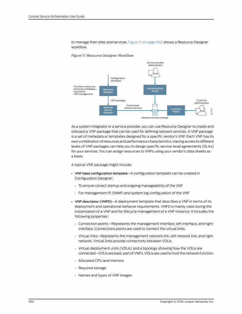
to manage their sites and services. Figure 11 on page 652 shows a Resource Designer
workflow.
Figure 11: Resource DesignerWorkflow
CustomerPortal
NetworkServiceDesigner
ResourceDesigner
Service provideradministrator
AdministrationPortal
Network services catalog
Customeradministrator
g043752
Configurationtemplates
VNF packages
Customizednetwork services
Functions, resources,protocols, metadata….required forVNFmanagement
As a system integrator or a service provider, you can use Resource Designer to create and
onboard a VNF package that can be used for defining network services. A VNF package
is a set of metadata or templates designed for a specific vendor’s VNF. Each VNF has its
owncombinationof resourcesandperformancecharacteristics.Havingaccess todifferent
levels of VNF packages can help you to design specific service-level agreements (SLAs)
for your services. You can assign resources to VNFs using your vendor’s data sheets as
a basis.
A typical VNF packagemight include:
• VNF base configuration template—A configuration template can be created in
Configuration Designer:
• To ensure correct startup and ongoing manageability of the VNF
• For management IP, SNMP, and system log configuration of the VNF
• VNF descriptor (VNFD)—A deployment template that describes a VNF in terms of its
deployment and operational behavior requirements. VNFD is mainly used during the
instantiation of a VNF and for lifecyclemanagement of a VNF instance. It includes the
following properties:
• Connection points—Represents the management interface, left interface, and right
interface. Connections points are used to connect the virtual links.
• Virtual links—Represents the management network link, left network link, and right
network. Virtual links provide connectivity between VDUs.
• Virtual deployment units (VDUs) and a topology showing how the VDUs are
connected—VDUsarebasicpartofVNFs.VDUsareused tohost thenetwork function.
• Allocated CPU andmemory
• Required storage
• Names and types of VNF images
Copyright © 2018, Juniper Networks, Inc.652
Contrail Service Orchestration User Guide
• Deployment flavors—A differentiated option such as Gold, Silver, or Bronze with an
appropriate SLAmetric.
• VNF auto-scale policies
• VNFManager plug-in—A plug-in type and name. For example, a VNF Manager for VNF
lifecycle management.
• Supported function chains—Sequences of network functions, such as firewall, NAT, or
WAN optimization, that the VNF packages offers.
SomeVNFs, like vSRX, supportmultiple functions and service chains. For example, vSRX
can be deployed in the context ofmultiple functions such as firewalls, carrier-grade NAT,
IDP, UTM, malware, and others.
RelatedDocumentation
Accessing the Resource Designer on page 654•
• Changing Your Password on page 636
• Using the Resource Designer on page 653
Using the Resource Designer
Use the Resource Designer to create a VNF package or modify an existing one. Follow
these steps to get started with the Resource Designer:
• Learn about the Resource Designer. See “Resource Designer Overview” on page 651.
• Log into the Resource Designer. See “Accessing the Resource Designer” on page 654.
To create a VNF package:
1. Create a request for a VNF package. See “Creating Requests for VNF Packages” on
page 656.
2. Design a VNF package. See “Designing VNF Packages” on page 657.
3. Publish the VNF package to the Network Service Designer. See “Publishing VNF
Packages” on page 665.
You can also perform the following tasks using the Resource Designer:
• Clone a VNF package. See “Cloning VNF Packages” on page 667.
• Import a VNF package. See “Importing VNF Packages” on page 668.
• Export a VNF package. See “Exporting VNF Packages” on page 668.
RelatedDocumentation
Resource Designer Overview on page 651•
• Accessing the Resource Designer on page 654
653Copyright © 2018, Juniper Networks, Inc.
Chapter 49: Resource Designer
Accessing the Resource Designer
To access the Resource Designer:
1. Reviewthekeystoneusernameandpassword that youdefined forContrailOpenStack.
• For a centralized deployment, you can view these settings on the Contrail configure
and control node in the files /etc/contrail/keystonerc and /etc/contrail/openstackrc.
• For a distributed deployment, you can view these settings on the central
infrastructure node in the file /etc/keystone/keystonerc.
• The default username is cspadmin and the default password is passw0rd.
2. Using aWeb browser, access the URL for the Resource Designer.
For example, if the IP address of the host on which Resource Designer resides is
192.0.2.1, the URL would be https://192.0.2.1:83/rd-ui/index.html.
3. Log in with the OpenStack Keystone username and password.
RelatedDocumentation
Resource Designer Overview on page 651•
• Using the Resource Designer on page 653
About the Requests Page for the Resource Designer
To access this page, click Home > Requests.
Use the Requests page to request a new VNF package. A VNF package is a package of
device metadata or templates for a specific vendor VNF. You can also view the open
VNF package requests with the request name, date, and time.
Tasks You Can Perform
You can perform the following tasks from this page:
• Create a request to design a VNF package. See “Creating Requests for VNF Packages”
on page 656.
• Design a new VNF package. See “Designing VNF Packages” on page 657.
Field Descriptions
Table 309 on page 654 provides guidelines on using the fields on the Requests page for
the Resource Designer.
Table 309: Fields on the Requests Page for the Resource Designer
DescriptionField
Requests Page
Copyright © 2018, Juniper Networks, Inc.654
Contrail Service Orchestration User Guide
Table 309: Fields on the Requests Page for the Resource Designer (continued)
DescriptionField
Click to request a new VNF package.
The New Request page allows you to define the requirements for your VNF package.
New Request
VNF Package Request
Hover over the bottom right of the package and click to design a VNF package.
The Basic VNF Information page appears. You can specify the basic information for the VNFpackage, supported VNF, and function chains.
Begin
Hover over the bottom right of the package and click to delete a VNF package request.
The VNF package request is deleted.
Delete
RelatedDocumentation
Resource Designer Overview on page 651•
• Using the Resource Designer on page 653
VNFOverview
Avirtualizednetwork function (VNF) isasoftwareapplicationused inaNetworkFunctions
Virtualization (NFV) implementation that has well defined interfaces, and provides one
or more component networking functions in a defined way. For example, a security VNF
provides Network Address Translation (NAT) and firewall component functions.
For the Cloud CPE solution in a centralized deployment model, you design network
services for customers based on VNFs. Each VNF used in the network service is deployed
in its own virtual machine (VM). The connections between VNFs depend on how VIMs
define them over the NFV Infrastructure (NFVI).
For the Cloud CPE solution in distributed deployment model, the Open vSwitch (OVS)
bridges are used within the NFX hypervisor.
You can specify the following required resources for a VNF package when you create it
in Resource Designer.
• Number of virtual CPUs
• Virtual memory (MB)
• Virtual disk capacity (MB)
• License cost
The Cloud CPE solution supports a range of Juniper Networks and third-party VNFs.
Vendors can provide multiple versions of a VNF that offer differentiated performance.
You can see available VNFs and their specifications and resource requirements in the
VNF catalog of the Network Service Designer tool. Table 310 on page 656 lists the VNFs
that are currently supported by the Cloud CPE Solution.
655Copyright © 2018, Juniper Networks, Inc.
Chapter 49: Resource Designer
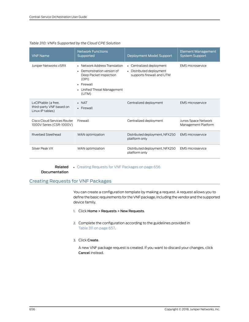
Table 310: VNFs Supported by the Cloud CPE Solution
Element ManagementSystem SupportDeployment Model Support
Network FunctionsSupportedVNF Name
EMSmicroservice• Centralized deployment
• Distributed deploymentsupports firewall and UTM
• NetworkAddressTranslation
• Demonstration version ofDeep Packet Inspection(DPI)
• Firewall
• Unified Threat Management(UTM)
Juniper Networks vSRX
EMSmicroserviceCentralized deployment• NAT
• Firewall
LxCIPtable (a free,third-party VNF based onLinux IP tables)
Junos Space NetworkManagement Platform
Centralized deploymentFirewallCisco Cloud Services Router1000VSeries (CSR-1000V)
EMSmicroserviceDistributeddeployment,NFX250platform only
WAN optimizationRiverbed Steelhead
EMSmicroserviceDistributeddeployment,NFX250platform only
WAN optimizationSilver Peak VX
RelatedDocumentation
Creating Requests for VNF Packages on page 656•
Creating Requests for VNF Packages
You can create a configuration template by making a request. A request allows you to
define thebasic requirements for theVNFpackage, including thevendorandthesupported
device family.
1. Click Home > Requests > NewRequests.
2. Complete the configuration according to the guidelines provided in
Table 311 on page 657.
3. Click Create.
A new VNF package request is created. If you want to discard your changes, click
Cancel instead.
Copyright © 2018, Juniper Networks, Inc.656
Contrail Service Orchestration User Guide
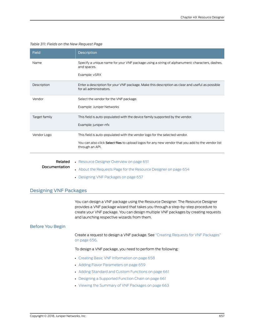
Table 311: Fields on the New Request Page
DescriptionField
Specify a unique name for your VNF package using a string of alphanumeric characters, dashes,and spaces.
Example: vSRX
Name
Enter a description for your VNF package. Make this description as clear and useful as possiblefor all administrators.
Description
Select the vendor for the VNF package.
Example: Juniper Networks
Vendor
This field is auto-populated with the device family supported by the vendor.
Example: juniper-nfx
Target family
This field is auto-populated with the vendor logo for the selected vendor.
You can also click Select files to upload logos for any new vendor that you add to the vendor listthrough an API.
Vendor Logo
RelatedDocumentation
Resource Designer Overview on page 651•
• About the Requests Page for the Resource Designer on page 654
• Designing VNF Packages on page 657
Designing VNF Packages
You can design a VNF package using the Resource Designer. The Resource Designer
provides a VNF package wizard that takes you through a step-by-step procedure to
create your VNF package. You can design multiple VNF packages by creating requests
and launching respective wizards from them.
Before You Begin
Create a request to design a VNF package. See “Creating Requests for VNF Packages”
on page 656.
To design a VNF package, you need to perform the following:
• Creating Basic VNF Information on page 658
• Adding Flavor Parameters on page 659
• Adding Standard and Custom Functions on page 661
• Designing a Supported Function Chain on page 661
• Viewing the Summary of VNF Packages on page 663
657Copyright © 2018, Juniper Networks, Inc.
Chapter 49: Resource Designer
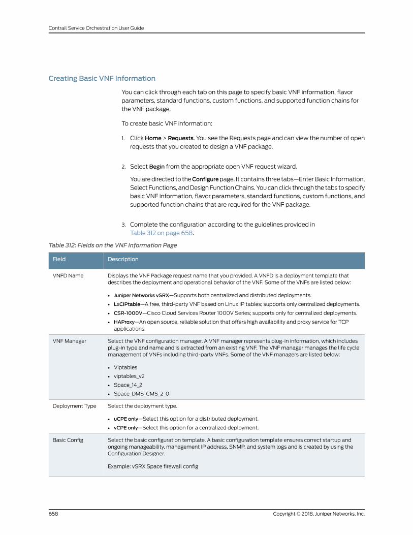
Creating Basic VNF Information
You can click through each tab on this page to specify basic VNF information, flavor
parameters, standard functions, custom functions, and supported function chains for
the VNF package.
To create basic VNF information:
1. ClickHome > Requests. You see the Requests page and can view the number of open
requests that you created to design a VNF package.
2. Select Begin from the appropriate open VNF request wizard.
Youaredirected to theConfigurepage. It contains three tabs—EnterBasic Information,
Select Functions, andDesignFunctionChains. Youcanclick through the tabs to specify
basic VNF information, flavor parameters, standard functions, custom functions, and
supported function chains that are required for the VNF package.
3. Complete the configuration according to the guidelines provided in
Table 312 on page 658.
Table 312: Fields on the VNF Information Page
DescriptionField
Displays the VNF Package request name that you provided. A VNFD is a deployment template thatdescribes the deployment and operational behavior of the VNF. Some of the VNFs are listed below:
• Juniper Networks vSRX—Supports both centralized and distributed deployments.
• LxCIPtable—A free, third-party VNF based on Linux IP tables; supports only centralized deployments.
• CSR-1000V—Cisco Cloud Services Router 1000V Series; supports only for centralized deployments.
• HAProxy—An open source, reliable solution that offers high availability and proxy service for TCPapplications.
VNFD Name
Select the VNF configuration manager. A VNFmanager represents plug-in information, which includesplug-in type and name and is extracted from an existing VNF. The VNFmanager manages the life cyclemanagement of VNFs including third-party VNFs. Some of the VNFmanagers are listed below:
• Viptables
• viptables_v2
• Space_14_2
• Space_DMS_CMS_2_0
VNFManager
Select the deployment type.
• uCPE only—Select this option for a distributed deployment.
• vCPE only—Select this option for a centralized deployment.
Deployment Type
Select the basic configuration template. A basic configuration template ensures correct startup andongoing manageability, management IP address, SNMP, and system logs and is created by using theConfiguration Designer.
Example: vSRX Space firewall config
Basic Config
Copyright © 2018, Juniper Networks, Inc.658
Contrail Service Orchestration User Guide
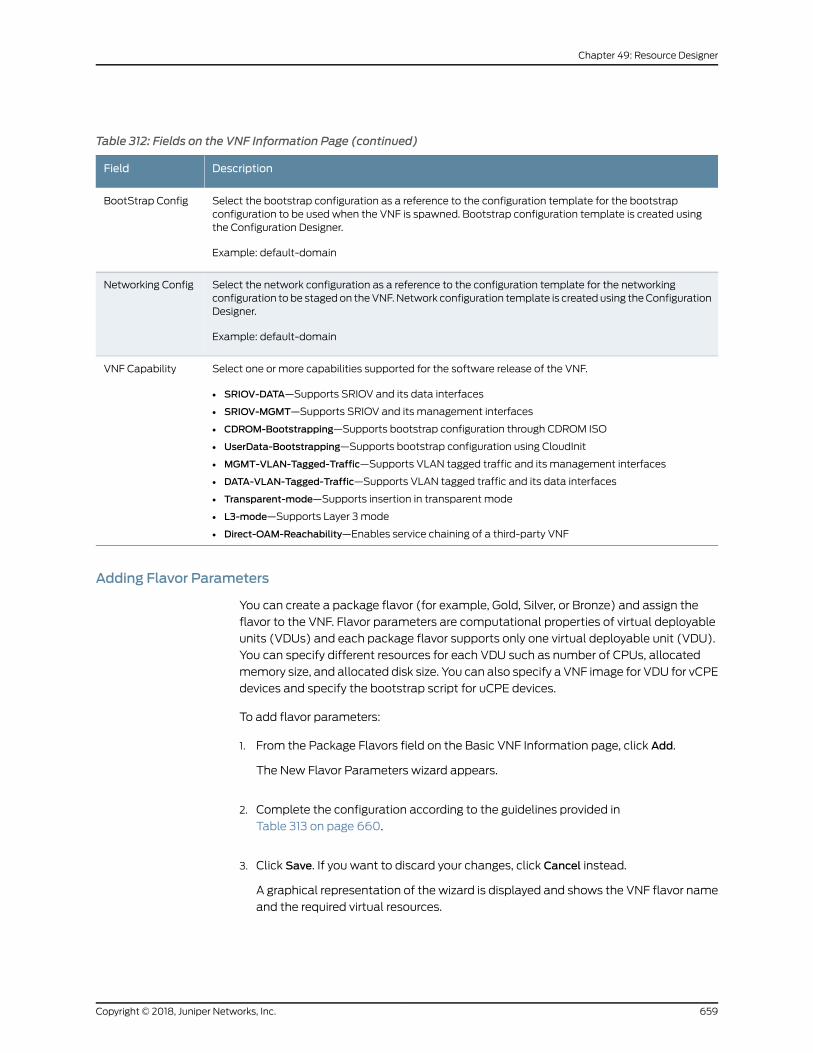
Table 312: Fields on the VNF Information Page (continued)
DescriptionField
Select the bootstrap configuration as a reference to the configuration template for the bootstrapconfiguration to be used when the VNF is spawned. Bootstrap configuration template is created usingthe Configuration Designer.
Example: default-domain
BootStrap Config
Select the network configuration as a reference to the configuration template for the networkingconfiguration to be stagedon theVNF.Network configuration template is created using theConfigurationDesigner.
Example: default-domain
Networking Config
Select one or more capabilities supported for the software release of the VNF.
• SRIOV-DATA—Supports SRIOV and its data interfaces
• SRIOV-MGMT—Supports SRIOV and its management interfaces
• CDROM-Bootstrapping—Supports bootstrap configuration through CDROM ISO
• UserData-Bootstrapping—Supports bootstrap configuration using CloudInit
• MGMT-VLAN-Tagged-Traffic—Supports VLAN tagged traffic and its management interfaces
• DATA-VLAN-Tagged-Traffic—Supports VLAN tagged traffic and its data interfaces
• Transparent-mode—Supports insertion in transparent mode
• L3-mode—Supports Layer 3 mode
• Direct-OAM-Reachability—Enables service chaining of a third-party VNF
VNF Capability
Adding Flavor Parameters
You can create a package flavor (for example, Gold, Silver, or Bronze) and assign the
flavor to the VNF. Flavor parameters are computational properties of virtual deployable
units (VDUs) and each package flavor supports only one virtual deployable unit (VDU).
You can specify different resources for each VDU such as number of CPUs, allocated
memory size, and allocated disk size. You can also specify a VNF image for VDU for vCPE
devices and specify the bootstrap script for uCPE devices.
To add flavor parameters:
1. From the Package Flavors field on the Basic VNF Information page, click Add.
The New Flavor Parameters wizard appears.
2. Complete the configuration according to the guidelines provided in
Table 313 on page 660.
3. Click Save. If you want to discard your changes, click Cancel instead.
A graphical representation of the wizard is displayed and shows the VNF flavor name
and the required virtual resources.
659Copyright © 2018, Juniper Networks, Inc.
Chapter 49: Resource Designer
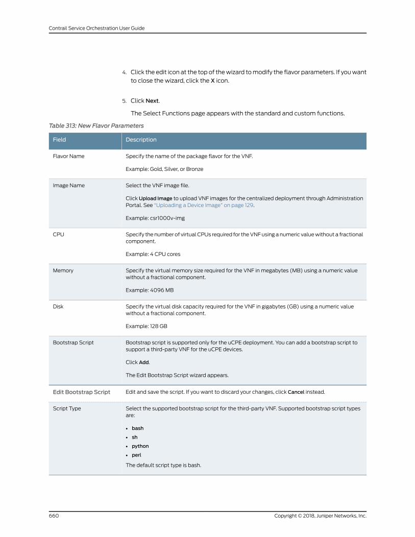
4. Click the edit icon at the top of thewizard tomodify the flavor parameters. If youwant
to close the wizard, click the X icon.
5. Click Next.
The Select Functions page appears with the standard and custom functions.
Table 313: New Flavor Parameters
DescriptionField
Specify the name of the package flavor for the VNF.
Example: Gold, Silver, or Bronze
Flavor Name
Select the VNF image file.
ClickUpload Image to upload VNF images for the centralized deployment through AdministrationPortal. See “Uploading a Device Image” on page 129.
Example: csr1000v-img
Image Name
Specify thenumber of virtual CPUs required for theVNFusinganumeric valuewithout a fractionalcomponent.
Example: 4 CPU cores
CPU
Specify the virtual memory size required for the VNF in megabytes (MB) using a numeric valuewithout a fractional component.
Example: 4096MB
Memory
Specify the virtual disk capacity required for the VNF in gigabytes (GB) using a numeric valuewithout a fractional component.
Example: 128 GB
Disk
Bootstrap script is supported only for the uCPE deployment. You can add a bootstrap script tosupport a third-party VNF for the uCPE devices.
Click Add.
The Edit Bootstrap Script wizard appears.
Bootstrap Script
Edit and save the script. If you want to discard your changes, click Cancel instead.Edit Bootstrap Script
Select the supported bootstrap script for the third-party VNF. Supported bootstrap script typesare:
• bash
• sh
• python
• perl
The default script type is bash.
Script Type
Copyright © 2018, Juniper Networks, Inc.660
Contrail Service Orchestration User Guide
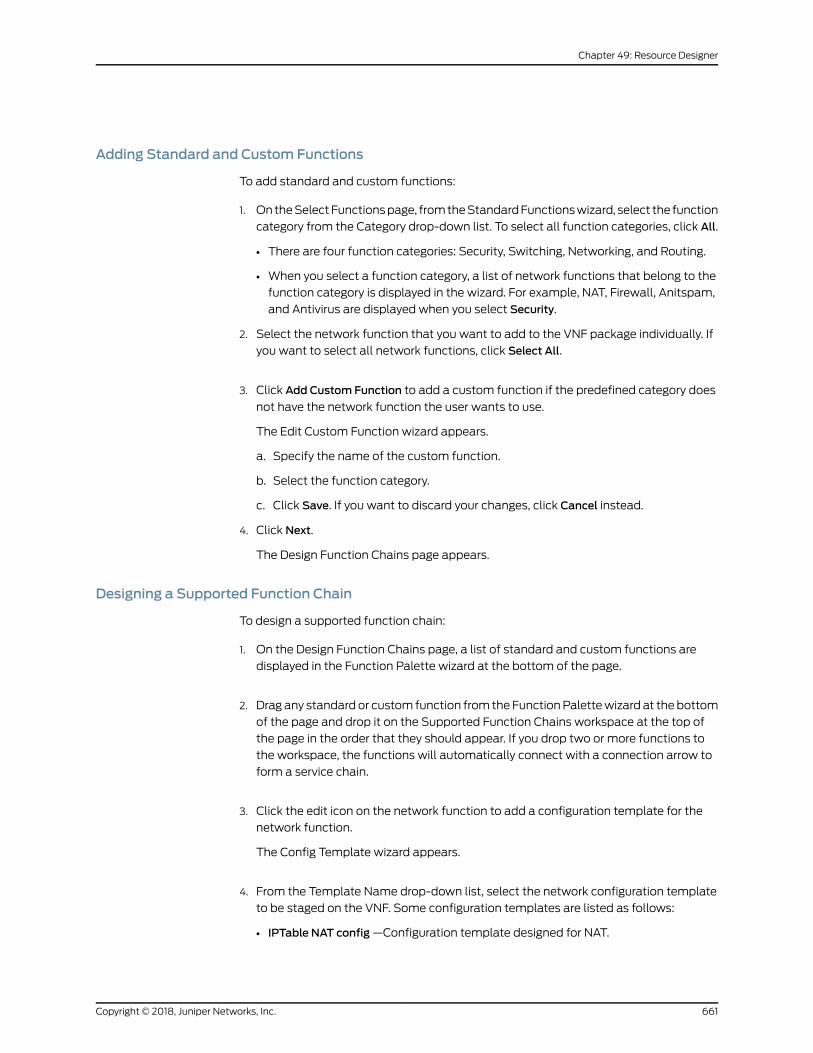
Adding Standard and Custom Functions
To add standard and custom functions:
1. OntheSelectFunctionspage, fromtheStandardFunctionswizard, select the function
category from the Category drop-down list. To select all function categories, click All.
• There are four function categories: Security, Switching, Networking, and Routing.
• When you select a function category, a list of network functions that belong to the
function category is displayed in the wizard. For example, NAT, Firewall, Anitspam,
and Antivirus are displayed when you select Security.
2. Select the network function that you want to add to the VNF package individually. If
you want to select all network functions, click Select All.
3. Click Add Custom Function to add a custom function if the predefined category does
not have the network function the user wants to use.
The Edit Custom Function wizard appears.
a. Specify the name of the custom function.
b. Select the function category.
c. Click Save. If you want to discard your changes, click Cancel instead.
4. Click Next.
The Design Function Chains page appears.
Designing a Supported Function Chain
To design a supported function chain:
1. On the Design Function Chains page, a list of standard and custom functions are
displayed in the Function Palette wizard at the bottom of the page.
2. Drag any standard or custom function from the FunctionPalettewizard at the bottom
of the page and drop it on the Supported Function Chains workspace at the top of
the page in the order that they should appear. If you drop two or more functions to
the workspace, the functions will automatically connect with a connection arrow to
form a service chain.
3. Click the edit icon on the network function to add a configuration template for the
network function.
The Config Template wizard appears.
4. From the Template Name drop-down list, select the network configuration template
to be staged on the VNF. Some configuration templates are listed as follows:
• IPTable NAT config—Configuration template designed for NAT.
661Copyright © 2018, Juniper Networks, Inc.
Chapter 49: Resource Designer
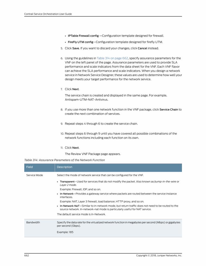
• IPTable Firewall config—Configuration template designed for firewall.
• FireFly UTM config—Configuration template designed for firefly UTM.
5. Click Save. If you want to discard your changes, click Cancel instead.
6. Using the guidelines in Table 314 on page 662, specify assurance parameters for the
VNF on the left panel of the page. Assurance parameters are used to provide SLA
performance and scale indicators from the data sheet for the VNF. Each VNF flavor
can achieve the SLA performance and scale indicators. When you design a network
service inNetwork ServiceDesigner, these values are used to determine howwell your
design meets your target performance for the network service.
7. Click Next.
The service chain is created and displayed in the same page. For example,
Antispam-UTM-NAT-Antivirus.
8. If you usemore than one network function in the VNF package, click Service Chain to
create the next combination of services.
9. Repeat steps 4 through 6 to create the service chain.
10. Repeat steps 6 through 9 until you have covered all possible combinations of the
network functions including each function on its own.
11. Click Next.
The Review VNF Package page appears.
Table 314: Assurance Parameters of the Network Function
DescriptionField
Select the mode of network service that can be configured for the VNF.
• Transparent—Used for services that do not modify the packet. Also known as bump-in-the-wire orLayer 2 mode.
Example: Firewall, IDP, and so on.
• In-Network—Provides a gateway service where packets are routed between the service instanceinterfaces.
Example: NAT, Layer 3 firewall, load balancer, HTTP proxy, and so on.
• In-Network-NaT—Similar to in-network mode, but return traffic does not need to be routed to thesource network. In-network-nat mode is particularly useful for NAT service.
The default service mode is In-Network.
Service Mode
Specify thedata rate for the virtualizednetwork function inmegabytesper second (Mbps)or gigabytesper second (Gbps).
Example: 185
Bandwidth
Copyright © 2018, Juniper Networks, Inc.662
Contrail Service Orchestration User Guide
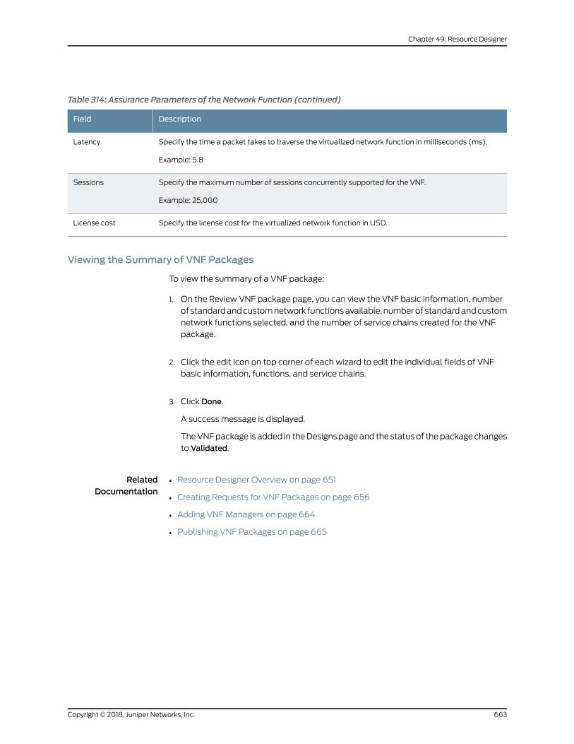
Table 314: Assurance Parameters of the Network Function (continued)
DescriptionField
Specify the time a packet takes to traverse the virtualized network function in milliseconds (ms).
Example: 5.8
Latency
Specify the maximum number of sessions concurrently supported for the VNF.
Example: 25,000
Sessions
Specify the license cost for the virtualized network function in USD.License cost
Viewing the Summary of VNF Packages
To view the summary of a VNF package:
1. On the Review VNF package page, you can view the VNF basic information, number
of standardandcustomnetwork functionsavailable, numberof standardandcustom
network functions selected, and the number of service chains created for the VNF
package.
2. Click the edit icon on top corner of each wizard to edit the individual fields of VNF
basic information, functions, and service chains.
3. Click Done.
A success message is displayed.
TheVNFpackage is added in theDesigns pageand the status of thepackage changes
to Validated.
RelatedDocumentation
Resource Designer Overview on page 651•
• Creating Requests for VNF Packages on page 656
• Adding VNFManagers on page 664
• Publishing VNF Packages on page 665
663Copyright © 2018, Juniper Networks, Inc.
Chapter 49: Resource Designer
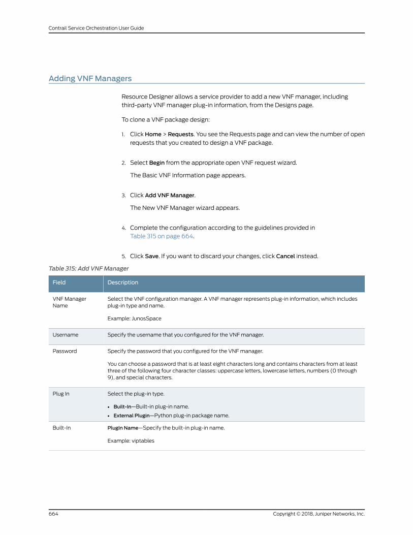
Adding VNFManagers
Resource Designer allows a service provider to add a new VNFmanager, including
third-party VNFmanager plug-in information, from the Designs page.
To clone a VNF package design:
1. ClickHome > Requests. You see the Requests page and can view the number of open
requests that you created to design a VNF package.
2. Select Begin from the appropriate open VNF request wizard.
The Basic VNF Information page appears.
3. Click Add VNFManager.
The New VNFManager wizard appears.
4. Complete the configuration according to the guidelines provided in
Table 315 on page 664.
5. Click Save. If you want to discard your changes, click Cancel instead.
Table 315: Add VNFManager
DescriptionField
Select the VNF configuration manager. A VNFmanager represents plug-in information, which includesplug-in type and name.
Example: JunosSpace
VNFManagerName
Specify the username that you configured for the VNFmanager.Username
Specify the password that you configured for the VNFmanager.
You can choose a password that is at least eight characters long and contains characters from at leastthree of the following four character classes: uppercase letters, lowercase letters, numbers (0 through9), and special characters.
Password
Select the plug-in type.
• Built-In—Built-in plug-in name.
• External Plugin—Python plug-in package name.
Plug In
PlugIn Name—Specify the built-in plug-in name.
Example: viptables
Built-In
Copyright © 2018, Juniper Networks, Inc.664
Contrail Service Orchestration User Guide
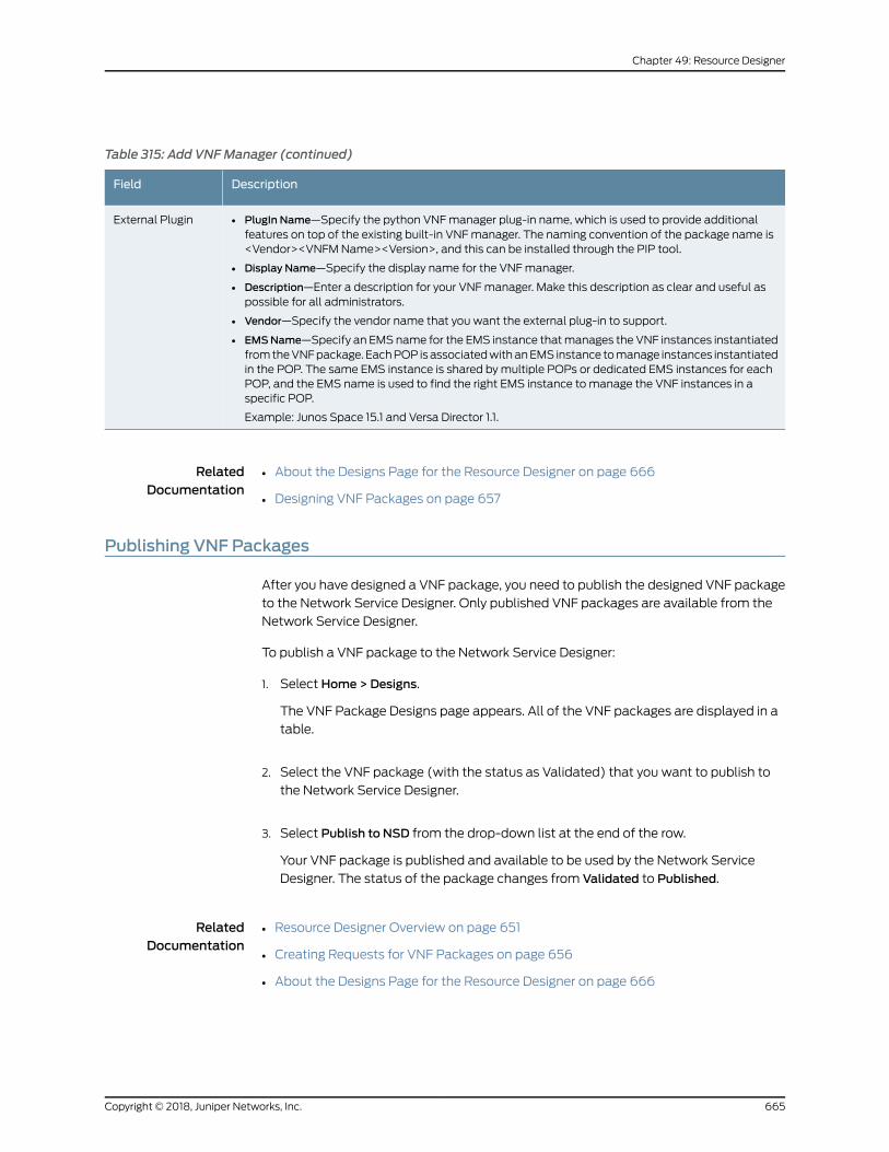
Table 315: Add VNFManager (continued)
DescriptionField
• PlugIn Name—Specify the python VNFmanager plug-in name, which is used to provide additionalfeatures on top of the existing built-in VNFmanager. The naming convention of the package name is<Vendor><VNFMName><Version>, and this can be installed through the PIP tool.
• Display Name—Specify the display name for the VNFmanager.
• Description—Enter a description for your VNFmanager. Make this description as clear and useful aspossible for all administrators.
• Vendor—Specify the vendor name that you want the external plug-in to support.
• EMSName—Specify an EMS name for the EMS instance thatmanages the VNF instances instantiatedfromtheVNFpackage. EachPOP isassociatedwithanEMS instance tomanage instances instantiatedin the POP. The same EMS instance is shared bymultiple POPs or dedicated EMS instances for eachPOP, and the EMS name is used to find the right EMS instance to manage the VNF instances in aspecific POP.
Example: Junos Space 15.1 and Versa Director 1.1.
External Plugin
RelatedDocumentation
About the Designs Page for the Resource Designer on page 666•
• Designing VNF Packages on page 657
Publishing VNF Packages
After you have designed a VNF package, you need to publish the designed VNF package
to the Network Service Designer. Only published VNF packages are available from the
Network Service Designer.
To publish a VNF package to the Network Service Designer:
1. Select Home > Designs.
The VNF Package Designs page appears. All of the VNF packages are displayed in a
table.
2. Select the VNF package (with the status as Validated) that you want to publish to
the Network Service Designer.
3. Select Publish to NSD from the drop-down list at the end of the row.
Your VNF package is published and available to be used by the Network Service
Designer. The status of the package changes from Validated to Published.
RelatedDocumentation
Resource Designer Overview on page 651•
• Creating Requests for VNF Packages on page 656
• About the Designs Page for the Resource Designer on page 666
665Copyright © 2018, Juniper Networks, Inc.
Chapter 49: Resource Designer
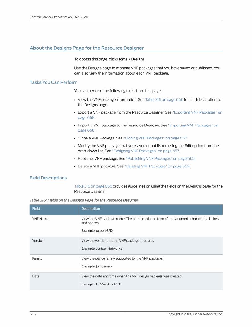
About the Designs Page for the Resource Designer
To access this page, click Home > Designs.
Use the Designs page to manage VNF packages that you have saved or published. You
can also view the information about each VNF package.
Tasks You Can Perform
You can perform the following tasks from this page:
• View theVNFpackage information. See Table 316 on page666 for field descriptions of
the Designs page.
• Export a VNF package from the Resource Designer. See “Exporting VNF Packages” on
page 668.
• Import a VNF package to the Resource Designer. See “Importing VNF Packages” on
page 668.
• Clone a VNF Package. See “Cloning VNF Packages” on page 667.
• Modify the VNF package that you saved or published using the Edit option from the
drop-down list. See “Designing VNF Packages” on page 657.
• Publish a VNF package. See “Publishing VNF Packages” on page 665.
• Delete a VNF package. See “Deleting VNF Packages” on page 669.
Field Descriptions
Table 316 onpage666provides guidelines on using the fields on theDesigns page for the
Resource Designer.
Table 316: Fields on the Designs Page for the Resource Designer
DescriptionField
View the VNF package name. The name can be a string of alphanumeric characters, dashes,and spaces.
Example: ucpe-vSRX
VNF Name
View the vendor that the VNF package supports.
Example: Juniper Networks
Vendor
View the device family supported by the VNF package.
Example: juniper-srx
Family
View the data and time when the VNF design package was created.
Example: 01/24/2017 12:01
Date
Copyright © 2018, Juniper Networks, Inc.666
Contrail Service Orchestration User Guide
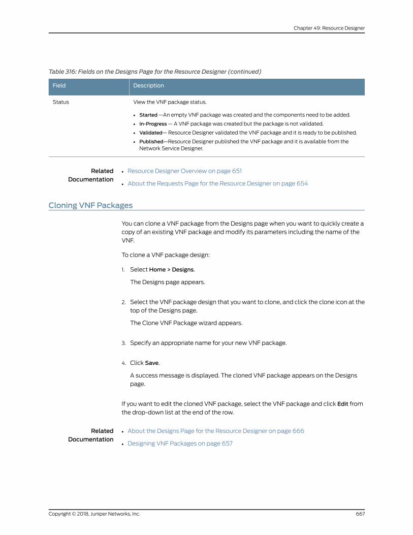
Table 316: Fields on the Designs Page for the Resource Designer (continued)
DescriptionField
View the VNF package status.
• Started—An empty VNF package was created and the components need to be added.
• In-Progress—A VNF package was created but the package is not validated.
• Validated—Resource Designer validated the VNF package and it is ready to be published.
• Published—Resource Designer published the VNF package and it is available from theNetwork Service Designer.
Status
RelatedDocumentation
Resource Designer Overview on page 651•
• About the Requests Page for the Resource Designer on page 654
Cloning VNF Packages
You can clone a VNF package from the Designs page when you want to quickly create a
copy of an existing VNF package andmodify its parameters including the name of the
VNF.
To clone a VNF package design:
1. Select Home > Designs.
The Designs page appears.
2. Select the VNF package design that youwant to clone, and click the clone icon at the
top of the Designs page.
The Clone VNF Package wizard appears.
3. Specify an appropriate name for your new VNF package.
4. Click Save.
A success message is displayed. The cloned VNF package appears on the Designs
page.
If you want to edit the cloned VNF package, select the VNF package and click Edit from
the drop-down list at the end of the row.
RelatedDocumentation
About the Designs Page for the Resource Designer on page 666•
• Designing VNF Packages on page 657
667Copyright © 2018, Juniper Networks, Inc.
Chapter 49: Resource Designer
Importing VNF Packages
You can import a VNF package design to the Designs page from third-party applications
and VNF packages from another Resource Designer. A VNF package design retains its
state when it is imported.
To import a VNF package design:
1. Select Home > Designs.
The Designs page appears.
2. Click the Import VNF package icon at the top of the Designs page.
The Import VNF wizard appears.
3. Click Select files to select the VNF JSON data file.
NOTE: You need to retain the file format as .json to successfully importthe VNF package design to the Resource Designer.
4. Click Import. If you want to discard the import process, click Cancel instead.
A success message is displayed indicating that the VNF is imported. The imported
VNF package appears on the Designs page.
RelatedDocumentation
About the Designs Page for the Resource Designer on page 666•
• Designing VNF Packages on page 657
Exporting VNF Packages
You can export a VNF package design from the Designs page when you want to use this
VNF package in another Resource Designer that is running in another customer’s server.
A VNF package design retains its state when it is exported.
To export a VNF package design:
1. Select Home > Designs.
The Designs page appears with a list of VNF packages.
2. Select the VNF package design that you want to export.
3. Select Export from the drop-down list at the end of the row.
Copyright © 2018, Juniper Networks, Inc.668
Contrail Service Orchestration User Guide
The VNF package JSON file opens at the bottom of the page.
4. Save the file to your computer.
You canmodify the parameters and rename the JSON filename if required.
RelatedDocumentation
About the Designs Page for the Resource Designer on page 666•
• Designing VNF Packages on page 657
• Importing VNF Packages on page 668
Deleting VNF Packages
To delete a VNF package design:
1. Select Home > Designs.
The Designs page appears with a list of VNF packages.
2. Select the VNF package design that you want to delete.
3. Select Delete from the drop-down list at the end of the row.
A page requesting confirmation for the deletion appears.
4. Click Yes to confirm.
The VNF package design is deleted.
RelatedDocumentation
• Resource Designer Overview on page 651
• About the Designs Page for the Resource Designer on page 666
669Copyright © 2018, Juniper Networks, Inc.
Chapter 49: Resource Designer

Copyright © 2018, Juniper Networks, Inc.670
Contrail Service Orchestration User Guide
CHAPTER 50
Network Service Designer introduction
• Network Service Designer Overview on page 671
• Accessing Network Service Designer on page 672
Network Service Designer Overview
Network Service Designer is a visual design tool to create andmanage network services
for the Juniper Networks Cloud CPE solution.
The Network Service Designer receives input from the Configuration Designer and
Resource Designer. Configuration Designer is used to create andmanage configuration
templates. The templates are based on a simple concept of configuration
parameterization. Parameterization facilitates the creation of versatile configuration
templates that can be easily used for different configurations. The different types of
configuration templates are device-level base configurations, service configurations, and
monitoring configurations. Resource Designer uses these configuration templates to
create VNF packages that are published to Network Service Designer. You combine
variousVNFs frommultiple vendors to createa service chainandpublish it to thenetwork
service catalog. The network service orchestrator instantiates the service chain to the
Cloud CPE solution.
With Network Service Designer you can:
• Create requests for new network services.
• Design customized network services for your customers.
• Design new standard network services that you can offer to all your customers.
• Update existing network services.
• Publish services to the network service catalog.
• Manage network services that you are designing or have published to the network
catalog.
• Configure somebasicparameters for theVNFsused inanetwork serviceand thevirtual
containers in which the VNFs reside.
RelatedDocumentation
Network Services and Service Chains Overview on page 673•
671Copyright © 2018, Juniper Networks, Inc.
• Accessing Network Service Designer on page 672
Accessing Network Service Designer
To access the Network Service Designer:
1. Review the OpenStack Keystone username and password that you defined.
• For a centralized deployment, you can view these settings on the Contrail configure
and control node in the files /etc/contrail/keystonerc and /etc/contrail/openstackrc.
• For a distributed deployment, you can view these settings on the central
infrastructure node in the file /etc/keystone/keystonerc.
• The default username is cspadmin and the default password is passw0rd.
2. Using aWeb browser, access the URL for the Network Services Designer.
For example, if the IP address of the host on which the Network Service Designer
resides is 192.0.2.1, then the URL would be https://192.0.2.1:83/nsd-ui/index.html.
3. Log in with the OpenStack Keystone username and password.
RelatedDocumentation
• Network Service Designer Overview on page 671
Copyright © 2018, Juniper Networks, Inc.672
Contrail Service Orchestration User Guide
CHAPTER 51
Creating Requests for Network Services
• Network Services and Service Chains Overview on page 673
• Performance Overview on page 674
• About the Requests Page for the Network Service Designer on page 675
• Creating Requests for Network Services on page 676
• Creating a Functional Service Chain on page 678
• Configuring Performance Goals on page 678
• Viewing Requests for Network Services on page 680
Network Services and Service Chains Overview
The terms network service and service chain are sometimes used interchangeably, but
they are not the same; you need to understand the difference between them:
• A network service is a final product offered to end users with a full description of its
functionality and specified performance.
Administrators deploy network services between two locations in a virtual network,
so that traffic traveling in a specific direction on that link is subject to action from that
service. This term is defined in the ETSI Network Functions Virtualization (NFV)
standard.
• A service chain refers to the structure of a network service, and consists of a set of
linked network functions, which are provided by specific virtualized network functions
(VNFs), with a defined direction for traffic flow and defined ingress and egress points.
Although not defined in the ETSI NFV standard, this term is regularly used in NFV and
software-defined networking (SDN).
You can create a service chain in the Network Service Designer by using:
• One VNF instance that provides one or more functions. See Figure 12 on page 674.
Using one VNF instance instead of multiple instances increases performance.
• Multiple instances of the same VNF, each providing certain functions. See
Figure 13 on page 674.
Usingmultiple instancesof the sameVNF lowersperformance, suchaswhen youwant
to create differentiated services.
673Copyright © 2018, Juniper Networks, Inc.
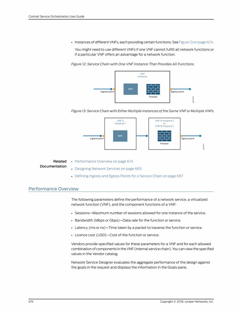
• InstancesofdifferentVNFs, eachproviding certain functions. SeeFigure 13onpage674.
Youmight need to use different VNFs if one VNF cannot fulfill all network functions or
if a particular VNF offers an advantage for a network function.
Figure 12: Service Chain with One VNF Instance That Provides All Functions
g043470
VNFInstance
Ingress point Egress point
Firewall
NAT
Figure 13: ServiceChainwithEitherMultiple Instancesof theSameVNForMultipleVNFs
g043471
VNF AInstance 1
Ingress point Egress point
Firewall
VNF A Instance 2or
VNF B Instance 1
NAT
RelatedDocumentation
Performance Overview on page 674•
• Designing Network Services on page 683
• Defining Ingress and Egress Points for a Service Chain on page 687
Performance Overview
The following parameters define the performance of a network service, a virtualized
network function (VNF), and the component functions of a VNF:
• Sessions—Maximum number of sessions allowed for one instance of the service.
• Bandwidth (Mbps or Gbps)—Data rate for the function or service.
• Latency (ms or ns)—Time taken by a packet to traverse the function or service.
• Licence cost (USD)—Cost of the function or service.
Vendors provide specified values for these parameters for a VNF and for each allowed
combinationof components in theVNF(internal servicechain).Youcanviewthespecified
values in the Vendor catalog.
Network Service Designer evaluates the aggregate performance of the design against
the goals in the request and displays the information in the Goals pane.
Copyright © 2018, Juniper Networks, Inc.674
Contrail Service Orchestration User Guide
RelatedDocumentation
Configuring Performance Goals on page 678•
• Monitoring Performance Goals on page 688
• VNF Overview on page 655
• Viewing Information About VNFs on page 683
• Designing Network Services on page 683
About the Requests Page for the Network Service Designer
To access this page, click Home> Requests.
Use the Requests page to create andmanage requests for new network services. You
must create a request before you can design a network service.
A request contains information about the required service, such as:
• The customer’s name.
• The requested functions in the network service. For example, NAT, UTM, and firewall.
• The performance goals for the service.
As soon as you start to design the network service, the request becomes a design, which
you track on the Designs page. See “About the Designs Page for the Network Service
Designer” on page 703.
Tasks You Can Perform
You can perform the following tasks from this page:
• Create requests for newnetwork services. See “CreatingRequests forNetworkServices”
on page 676.
• Specify a sequence of network functions that you want in the network service. See
“Creating a Functional Service Chain” on page 678.
• Viewopen requests for network services. See “ViewingRequests for Network Services”
on page 680.
Field Descriptions
Table 317 on page 675 provides guidelines on using the fields on the Requests page for
the Network Service Designer.
Table 317: Fields on the Requests Page for the Network Service Designer
DescriptionField
Click to request a new network service design. The New Request page allows you todefine the requirements for your network service design.
New Request
675Copyright © 2018, Juniper Networks, Inc.
Chapter 51: Creating Requests for Network Services
Table 317: Fields on the Requests Page for the Network Service Designer (continued)
DescriptionField
Hover over a saved request and click Begin to design a network service. The Build pageappears. You can specify the virtual network function, update the function configuration,and specify the performance goals.
Begin
Click to edit the network service design request details.Edit
Click to delete a network service design request.Delete
RelatedDocumentation
Network Service Designer Overview on page 671•
• About the Designs Page for the Network Service Designer on page 703
Creating Requests for Network Services
Youmust create a request before you can design a network service. When you create a
request for a network service, you define the requirements for the service, including the
required network functions and the performance goals.
To create a request for a network service:
1. Click Home in the toolbar and Requests in the left navigation bar.
2. Click NewRequest.
The Request Information page in which you specify information about the request
appears.
3. Configure the request information according to the guidelines provided in
Table 318 on page 677.
4. Click Next.
The Service Chain and Design Goals page appears, displaying the Goals pane, the
Functional Service Design area, and the Function Palette.
5. Configure the goals and service chain according to the guidelines provided in
Table 318 on page 677.
6. Click Next.
The Summary page appears that displays the details you entered for the request.
Copyright © 2018, Juniper Networks, Inc.676
Contrail Service Orchestration User Guide
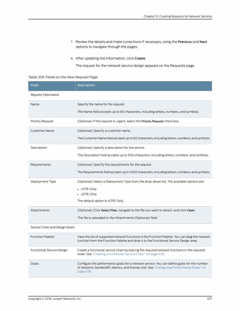
7. Review the details andmake corrections if necessary, using the Previous and Next
options to navigate through the pages.
8. After updating the information, click Create.
The request for the network service design appears on the Requests page.
Table 318: Fields on the New Request Page
DescriptionField
Request Information
Specify the name for the request.
The Name field accepts up to 60 characters, including letters, numbers, and symbols.
Name
(Optional) If the request is urgent, select the Priority Request check box.Priority Request
(Optional) Specify a customer name.
TheCustomerName fieldacceptsup to60characters, including letters, numbers, andsymbols.
Customer Name
(Optional) Specify a description for the service.
The Description field accepts up to 500 characters, including letters, numbers, and symbols.
Description
(Optional) Specify the requirements for the request.
TheRequirements fieldacceptsup to 1000characters, including letters, numbers, andsymbols.
Requirements
(Optional) Select a Deployment Type from the drop-down list. The available options are:
• vCPE-Only
• uCPE-Only
The default option is vCPE-Only.
Deployment Type
(Optional) Click Select Files, navigate to the file you want to attach, and clickOpen.
The file is uploaded to the Attachments (Optional) field.
Attachments
Service Chain and Design Goals
View the list of supported network functions in the Function Palette. You can drag the networkfunction from the Function Palette and drop it to the Functional Service Design area.
Function Palette
Create a functional service chain by placing the required network functions in the requiredorder. See “Creating a Functional Service Chain” on page 678.
Functional Service Design
Configure the performance goals for a network service. You can define goals for the numberof sessions, bandwidth, latency, and license cost. See “Configuring Performance Goals” onpage 678.
Goals
677Copyright © 2018, Juniper Networks, Inc.
Chapter 51: Creating Requests for Network Services
Table 318: Fields on the New Request Page (continued)
DescriptionField
Review the details andmake corrections if necessary, using the Previous and Next options tonavigate through the pages.
Summary
RelatedDocumentation
Network Services and Service Chains Overview on page 673•
• Performance Overview on page 674
• Designing Network Services on page 683
• Configuring Performance Goals on page 678
• Creating a Functional Service Chain on page 678
Creating a Functional Service Chain
NetworkServiceDesigner automatically connects thenetwork functions in theorder that
you place them in the design area. You can insert a function between two functions
already on the design pane. If youmake an error, you can use the delete icon or you can
right-click a component in the design area and delete the component.
NOTE: TheWAN links that are supported areWAN0,WAN1, andWAN2.
To create a functional service chain:
• Foracentralizeddeploymentmodel, draganddrop thenetwork functions in the required
order from the Function Palette to the Functional Service Design area.
• For a distributed deployment model, drag the network function from the Function
Palette and drop it to the Functional Service Design area in the following order:
• Between the ingress point and AppRouting function
• Between the AppRouting function andWAN links
• BetweenWAN Links and the egress point
RelatedDocumentation
Creating Requests for Network Services on page 676•
Configuring Performance Goals
To configure the performance goals of a network service:
1. Click Home> Requests > NewRequest .
2. Enter the request information and click Next.
Copyright © 2018, Juniper Networks, Inc.678
Contrail Service Orchestration User Guide
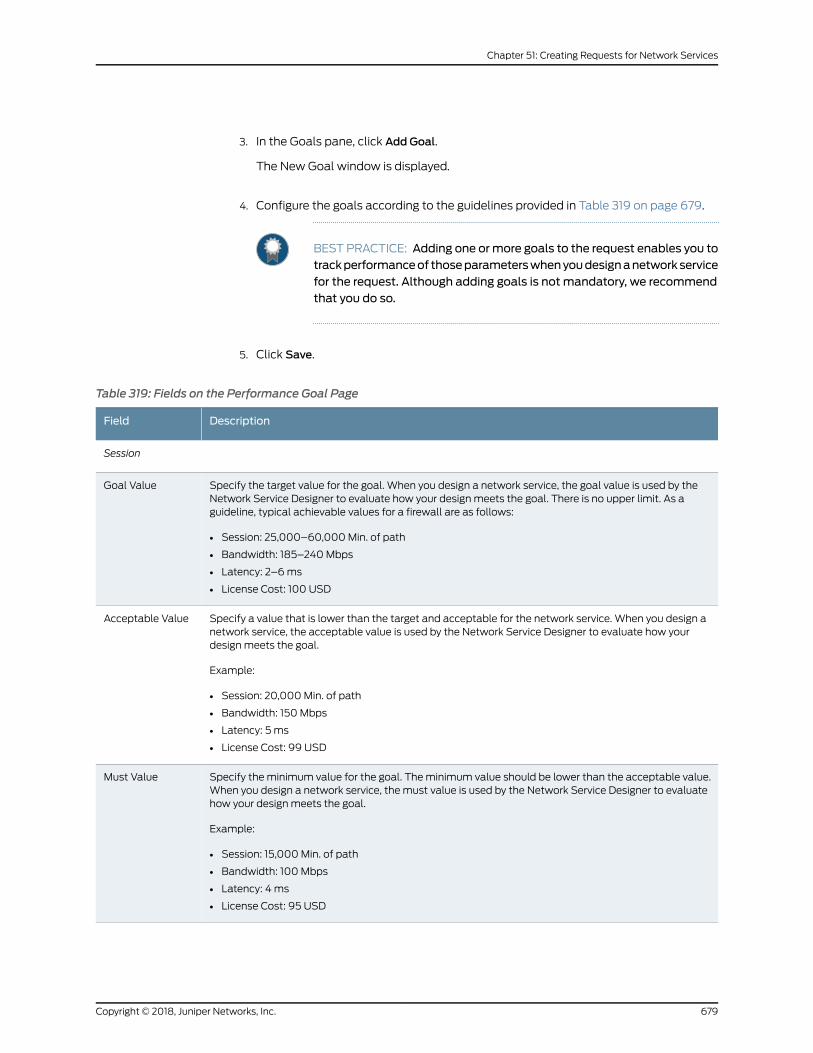
3. In the Goals pane, click Add Goal.
The New Goal window is displayed.
4. Configure the goals according to the guidelines provided in Table 319 on page 679.
BEST PRACTICE: Adding one ormore goals to the request enables you totrackperformanceof thoseparameterswhenyoudesignanetworkservicefor the request. Although adding goals is not mandatory, we recommendthat you do so.
5. Click Save.
Table 319: Fields on the Performance Goal Page
DescriptionField
Session
Specify the target value for the goal. When you design a network service, the goal value is used by theNetwork Service Designer to evaluate how your design meets the goal. There is no upper limit. As aguideline, typical achievable values for a firewall are as follows:
• Session: 25,000–60,000Min. of path
• Bandwidth: 185–240Mbps
• Latency: 2–6ms
• License Cost: 100 USD
Goal Value
Specify a value that is lower than the target and acceptable for the network service. When you design anetwork service, the acceptable value is used by the Network Service Designer to evaluate how yourdesign meets the goal.
Example:
• Session: 20,000Min. of path
• Bandwidth: 150 Mbps
• Latency: 5 ms
• License Cost: 99 USD
Acceptable Value
Specify the minimum value for the goal. Theminimum value should be lower than the acceptable value.When you design a network service, the must value is used by the Network Service Designer to evaluatehow your design meets the goal.
Example:
• Session: 15,000Min. of path
• Bandwidth: 100 Mbps
• Latency: 4 ms
• License Cost: 95 USD
Must Value
679Copyright © 2018, Juniper Networks, Inc.
Chapter 51: Creating Requests for Network Services
Table 319: Fields on the Performance Goal Page (continued)
DescriptionField
View themethod that is used by the Network Service Designer to evaluate how your design meets thegoal. You cannot edit this field.
Example:
• Session: Min. of path
If there are multiple VNFs in the service chain, then the VNF with the smallest bandwidth is chosen.
• Bandwidth: Min. of path
• Latency: Cumulative
• License Cost: Cumulative
Based on
Specify the measurement unit of the goal.
Example:
• Bandwidth: Mbps, Gbps
• Latency: ns, ms
• License Cost: USD
Unit
RelatedDocumentation
Performance Overview on page 674•
• Monitoring Performance Goals on page 688
Viewing Requests for Network Services
You can view the requests for a network service in a hierarchical grid view and tree view.
The grid view is the default option.
To view the requests for a network service in the tree view:
1. Select Home> Requests.
The Request page appears. All requests for a network service are displayed in the grid
view.
2. Click ShowDetails (hierarchy icon at the top left of the page).
The requests for the network service are listed in the Home page.
3. Select a request to view the detailed information about the customer, supported
function requirements, and design goals.
RelatedDocumentation
• About the Requests Page for the Network Service Designer on page 675
Copyright © 2018, Juniper Networks, Inc.680
Contrail Service Orchestration User Guide
CHAPTER 52
Creating Network Services
• About the Build Page for the Network Service Designer on page 681
• Viewing Information About VNFs on page 683
• Designing Network Services on page 683
• Connecting VNFs in a Service Chain on page 686
• Defining Ingress and Egress Points for a Service Chain on page 687
• Monitoring Performance Goals on page 688
• Configuring Network Services on page 689
• vSRX Configuration Settings on page 690
• LxCIPtable VNF Configuration Settings on page 697
• Cisco CSR-1000v VNF Configuration Settings on page 699
• Riverbed Steelhead VNF Configuration Settings on page 701
About the Build Page for the Network Service Designer
To access this page click Home > Designs >Design Name > Edit.
You can also view the Build page by following these steps:
1. Click Home in the toolbar and Requests in the left navigation bar.
2. Hover over an existing request.
A menu appears at the bottom right of the request that you are hovering over.
3. Click Begin.
The Build page appears.
Use the Build page to design, configure, save, and publish a network service. You can
also view VNFs to use in your design andmonitor how the design performs against your
target goals.
681Copyright © 2018, Juniper Networks, Inc.
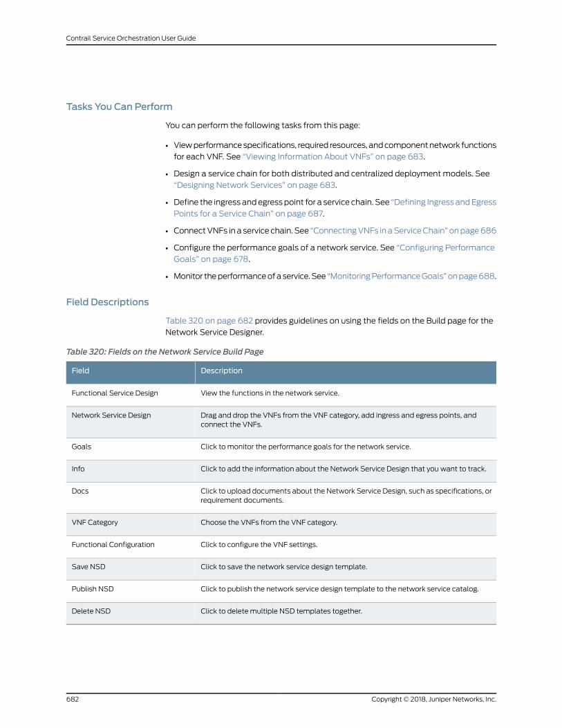
Tasks You Can Perform
You can perform the following tasks from this page:
• Viewperformancespecifications, required resources, andcomponentnetwork functions
for each VNF. See “Viewing Information About VNFs” on page 683.
• Design a service chain for both distributed and centralized deployment models. See
“Designing Network Services” on page 683.
• Define the ingressandegresspoint for a service chain. See “Defining IngressandEgress
Points for a Service Chain” on page 687.
• ConnectVNFs ina service chain. See “ConnectingVNFs inaServiceChain” onpage686
• Configure the performance goals of a network service. See “Configuring Performance
Goals” on page 678.
• Monitor theperformanceofaservice.See “MonitoringPerformanceGoals”onpage688.
Field Descriptions
Table 320 on page 682 provides guidelines on using the fields on the Build page for the
Network Service Designer.
Table 320: Fields on the Network Service Build Page
DescriptionField
View the functions in the network service.Functional Service Design
Drag and drop the VNFs from the VNF category, add ingress and egress points, andconnect the VNFs.
Network Service Design
Click to monitor the performance goals for the network service.Goals
Click to add the information about the Network Service Design that you want to track.Info
Click to upload documents about the Network Service Design, such as specifications, orrequirement documents.
Docs
Choose the VNFs from the VNF category.VNF Category
Click to configure the VNF settings.Functional Configuration
Click to save the network service design template.Save NSD
Click to publish the network service design template to the network service catalog.Publish NSD
Click to delete multiple NSD templates together.Delete NSD
Copyright © 2018, Juniper Networks, Inc.682
Contrail Service Orchestration User Guide
RelatedDocumentation
About the Designs Page for the Network Service Designer on page 703•
Viewing Information About VNFs
You can view performance specifications, required resources, and component network
functions for each VNF, which you created in the Resource Designer, in the VNF catalog.
Reviewing this information can help you to determine which VNF to use when you are
designing a network service.
To view information about a specific VNF:
1. Click the network function in the Vendor catalog.
The information window for the network function appears, displaying the following
information in the Details tab:
• Agraphical representationof thecompletenetwork functionwith ingressandegress
points.
• A list of resources required for the network function.
2. Click Functions.
You see the category of the network function, such as security, and the component
functions, such as NAT and firewall.
3. Click Service Chains to display:
• A list of the potential internal service chains (allowed combinations of component
functions) for this network function.
Lines without arrows connecting component functions in an internal service chain
indicate that the order of the functions does not matter.
• The performance specification for each internal service chain.
4. Click anywhere outside the window to close the VNF information window.
RelatedDocumentation
VNF Overview on page 655•
• Performance Overview on page 674
Designing Network Services
When you save a request it appears on the Requests page. You can then design a service
chain to fulfill the request, using VNFs in the Vendor catalog to provide the requested
network functions.
You can design the service chains for the following deployment models:
• Designing a Network Service for a Centralized Deployment on page 684
• Designing a Network Service for a Distributed Deployment on page 685
683Copyright © 2018, Juniper Networks, Inc.
Chapter 52: Creating Network Services
Designing a Network Service for a Centralized Deployment
To design a service chain for a centralized deployment model:
1. Click Home in the toolbar and Requests in the left navigation bar.
The Requests page appears, displaying the open requests.
2. Click Begin.
The Build page displays the requested network functions and the goals.
3. Click the first function in the chain.
The VNF catalog at the bottom right of the page is refreshed to show the VNFs that
provide this function.
4. Drag and drop a VNF from the catalog to the Network Service Design workspace.
The function appears inside the VNF image.
5. Add an ingress point to the first VNF in the chain.
The Performance Goals pane is refreshed to indicate how the network service design
meets the defined goals.
6. Click the next function in the chain.
The VNF catalog is refreshed to show only the VNFs that provide this function. If a
VNF in the Network Service Design workspace supports this function, a faded image
of the function appears inside the VNF image.
7. Choose a VNF for this function:
• To implement this function with the same VNF, click the faded image in the VNF
image.
• To implement this function with a different VNF, drag the VNF from the Vendor
catalog to the Network Service Design workspace.
8. Repeat Step 6 and Step 7 until you have assigned a VNF to each required network
function. If youmake an error in the design area, you can right-click and delete the
component.
9. If you have usedmultiple VNFs in your design, connect them by packet flow.
10. Add an egress point to the last VNF in the chain.
The Performance Goals pane is refreshed again to indicate how the network service
design meets the customer goals.
Copyright © 2018, Juniper Networks, Inc.684
Contrail Service Orchestration User Guide
11. Click Save NSD to save the design.
12. (Optional) Configure the Network Service.
13. Click Publish NSD to add the service to the catalog.
The Publish NSD page appears.
a. Specify a name (that customers see) for this network service.
The field accepts up to 60 characters, including letters, numbers, and symbols.
b. Specify a description of the service.
The field accepts up to 500 characters, including letters, numbers, and symbols.
c. Select the type of service from themenu.
d. Click Publish.
Designing a Network Service for a Distributed Deployment
To design a service chain for a distributed deployment model:
1. Click Home in the toolbar and Requests in the left navigation bar.
The Requests page appears, displaying the open requests.
2. Click Begin.
The Build page displays the requested network functions and the goals.
3. Click the first function in the chain.
The Vendor catalog is refreshed to show only the VNFs that provide this function.
4. Drag the VNF from the Vendor catalog and drop the network functions at the
appropriate points in the network chain to meet the requirements of your network.
The Performance Goals pane is refreshed to indicate how the network service design
meets the customer goals.
NOTE: The ingress point, egress points, and gateway router areautomatically updated for the distributed deploymentmodel.
5. Click the next function in the chain.
The Vendor catalog updates to show only the VNFs that provide this function. If a
VNF in the Network Service Design workspace supports this function, a faded image
of the function appears inside the VNF image.
685Copyright © 2018, Juniper Networks, Inc.
Chapter 52: Creating Network Services
6. If youhaveusedmultipleVNFs in yourdesign, thendraganddrop thenetwork functions
at the appropriate points in the network chain.
The Performance Goals pane again updates to indicate how the network service
design meets the customer goals.
7. Repeat Step 4 and Step 5 until you have assigned a VNF to the required network
function. If youmake an error, you can right-click a component in the network service
design area and delete the component.
8. (Optional) Click Function Configuration and configure the network service.
9. Click Save NSD to save the design.
10. Click Publish NSD to add the service to the catalog.
The Publish NSD page appears.
a. Specify an official name (that customers see) for this network service.
The field accepts up to 60 characters, including letters, numbers, and symbols.
b. Specify a description of the service for customers to read.
The field accepts up to 500 characters, including letters, numbers, and symbols.
c. Select the type of service from themenu.
d. Click Publish.
RelatedDocumentation
Network Services and Service Chains Overview on page 673•
• Performance Overview on page 674
• Defining Ingress and Egress Points for a Service Chain on page 687
• Connecting VNFs in a Service Chain on page 686
• Configuring Network Services on page 689
Connecting VNFs in a Service Chain
To connect VNFs in a service chain:
1. Click Connect, then click ELAN.
The dots that represent potential ingress and egress points on the VNFs enlarge.
2. Hover over the egress point of the first VNF until a green circle appears.
3. Click and hold the green circle, then drag the cursor to the green circle that appears
around the ingress point for the next VNF, and release the mouse button.
Copyright © 2018, Juniper Networks, Inc.686
Contrail Service Orchestration User Guide
A one-way arrow indicating the flow of traffic in the service chain appears.
4. Repeat Step 1 through Step 3 until you have connected all VNFs in the service chain.
RelatedDocumentation
Network Services and Service Chains Overview on page 673•
• Designing Network Services on page 683
Defining Ingress and Egress Points for a Service Chain
Todefine the ingress point and the egress point for a service chain that you are designing:
1. Click Ingress.
The dots that represent potential ingress and egress points on VNFs enlarge.
2. Click the dot that represents the ingress point for the service chain.
An arrow indicating the direction of traffic flow with the label I appears.
3. Click Egress.
4. Click the dot that represents the egress point for the service chain.
An arrow indicating the direction of traffic flow with the label E appears.
5. Click the egress point of the last VNF to define the egress point.
RelatedDocumentation
Network Services and Service Chains Overview on page 673•
• Designing Network Services on page 683
• Monitoring Performance Goals on page 688
687Copyright © 2018, Juniper Networks, Inc.
Chapter 52: Creating Network Services
Monitoring Performance Goals
Network Service Designer provides comprehensive information about the performance
of VNFs and their component network functions in the VNF catalog. Network Service
Designer also tracks the aggregate performance of a network service that you are
designing and saves the information to the network service catalog.
Minimizing the number of VNFs and VNF instances in a service chain optimizes the
performance of a network service. For example, using one VNF instance for both NAT
and firewall functions provides higher performance than using either separate instances
of the same VNF or different VNFs to provide the functions.
You specify performance goals for the service when you create a request for a network
service. When you are designing a service chain, you evaluate the performance of your
design against the requested goals.
Tomonitor the performance of a service that you are designing:
1. Click the right arrow in the Goals pane to view the performance goals.
2. Add an ingress point to the first VNF in the service chain immediately after you assign
that VNF to the first network function.
3. Monitor the values in the Goals pane as you design your service chain.
RelatedDocumentation
Network Services and Service Chains Overview on page 673•
• Performance Overview on page 674
• Designing Network Services on page 683
• Defining Ingress and Egress Points for a Service Chain on page 687
Copyright © 2018, Juniper Networks, Inc.688
Contrail Service Orchestration User Guide
Configuring Network Services
When you are designing a service chain or after you have designed a service chain, you
can configure settings for the VNFs in the chain. The configuration settings you can
configure are specified in Configuration Designer and the values for the settings are
specified in Resource Designer. The settings that you configure are:
• The virtual container in which the VNF resides.
• The network functions, such as NAT or firewall.
The settings that you can configure depend on the actual VNF. Manual configurations
are optional and override automatic configurations specified by the Cloud CPE solution
deployment script, other Contrail Service Orchestration components, or default settings
that you configured with Resource Designer.
To configure the network service:
1. View the service chain design on the Build page.
If the design is not currently visible on the Build page:
a. Click Home in the toolbar and Designs in the left navigation bar.
The list of saved and published designs appears.
b. Click Edit for the network service you want to configure.
The Build page appears, displaying the service chain design.
2. Click Function Configuration.
The Service page appears, displaying the VNFs in the service chain and the Base
Configure tab for the first VNF in the Functional Service Design workspace.
3. Specify the settings on the Base Configure tab.
This action configures the virtual machine in which the VNF resides.
BEST PRACTICE:• Complete all the settings in the Base Configure tab to optimize yourdeployment. End users can see these settings in Customer Portal orcustom access software and should not override them.
• Configure fewexample settings for the service. These example settingsmust be generic and not network-specific. End users can configureservice settings specific to their networks in Customer Portal.
4. (Optional) Specify settings on the other tabs for this VNF to customize a particular
function such as NAT.
689Copyright © 2018, Juniper Networks, Inc.
Chapter 52: Creating Network Services
End users can customize their own services with these settings in Customer Portal.
Settings that end users specify in Customer Portal override conflicting settings that
you specify in Network Service Designer.
5. Click the next VNF icon in the Configuration page.
6. Repeat Step 3 and Step 4.
7. Repeat Steps 5 through 7 for each VNF in the chain.
8. ClickOK.
The Service page closes.
RelatedDocumentation
vSRX Configuration Settings on page 690•
• LxCIPtable VNF Configuration Settings on page 697
• Cisco CSR-1000v VNF Configuration Settings on page 699
• Riverbed Steelhead VNF Configuration Settings on page 701
vSRX Configuration Settings
BEST PRACTICE: Service providers configure base settings for a VNF.Customers should not change these values unless directed to do so by theirservice provider. Service providers may provide some generic examples ofservice configurations for their customers. Customers can configureservices—for example, by creating policies—appropriate to their networks inCustomer Portal.
Use the information in the following tables to provide values for the available settings:
• Table 321 on page 691 shows the settings you can configure for the virtual machine
(VM) that contains the VNF.
• Table 322 on page 692 shows the firewall settings you can configure.
NOTE: Firewall is supported on both centralized deploymentmodel anddistributed deploymentmodel.
• Table 323onpage694shows theNetworkAddressTranslation (NAT) settings you can
configure.
Copyright © 2018, Juniper Networks, Inc.690
Contrail Service Orchestration User Guide
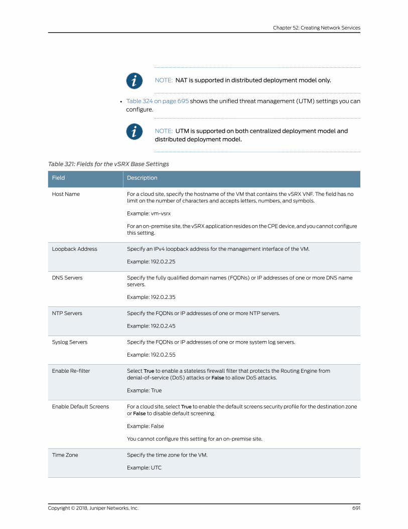
NOTE: NAT is supported in distributed deploymentmodel only.
• Table 324 on page 695 shows the unified threatmanagement (UTM) settings you can
configure.
NOTE: UTM is supported on both centralized deploymentmodel anddistributed deploymentmodel.
Table 321: Fields for the vSRX Base Settings
DescriptionField
For a cloud site, specify the hostname of the VM that contains the vSRX VNF. The field has nolimit on the number of characters and accepts letters, numbers, and symbols.
Example: vm-vsrx
Foranon-premisesite, thevSRXapplication resideson theCPEdevice, andyoucannotconfigurethis setting.
Host Name
Specify an IPv4 loopback address for the management interface of the VM.
Example: 192.0.2.25
Loopback Address
Specify the fully qualified domain names (FQDNs) or IP addresses of one or more DNS nameservers.
Example: 192.0.2.35
DNS Servers
Specify the FQDNs or IP addresses of one or more NTP servers.
Example: 192.0.2.45
NTP Servers
Specify the FQDNs or IP addresses of one or more system log servers.
Example: 192.0.2.55
Syslog Servers
Select True to enable a stateless firewall filter that protects the Routing Engine fromdenial-of-service (DoS) attacks or False to allow DoS attacks.
Example: True
Enable Re-filter
For a cloud site, select True to enable the default screens security profile for the destination zoneor False to disable default screening.
Example: False
You cannot configure this setting for an on-premise site.
Enable Default Screens
Specify the time zone for the VM.
Example: UTC
Time Zone
691Copyright © 2018, Juniper Networks, Inc.
Chapter 52: Creating Network Services
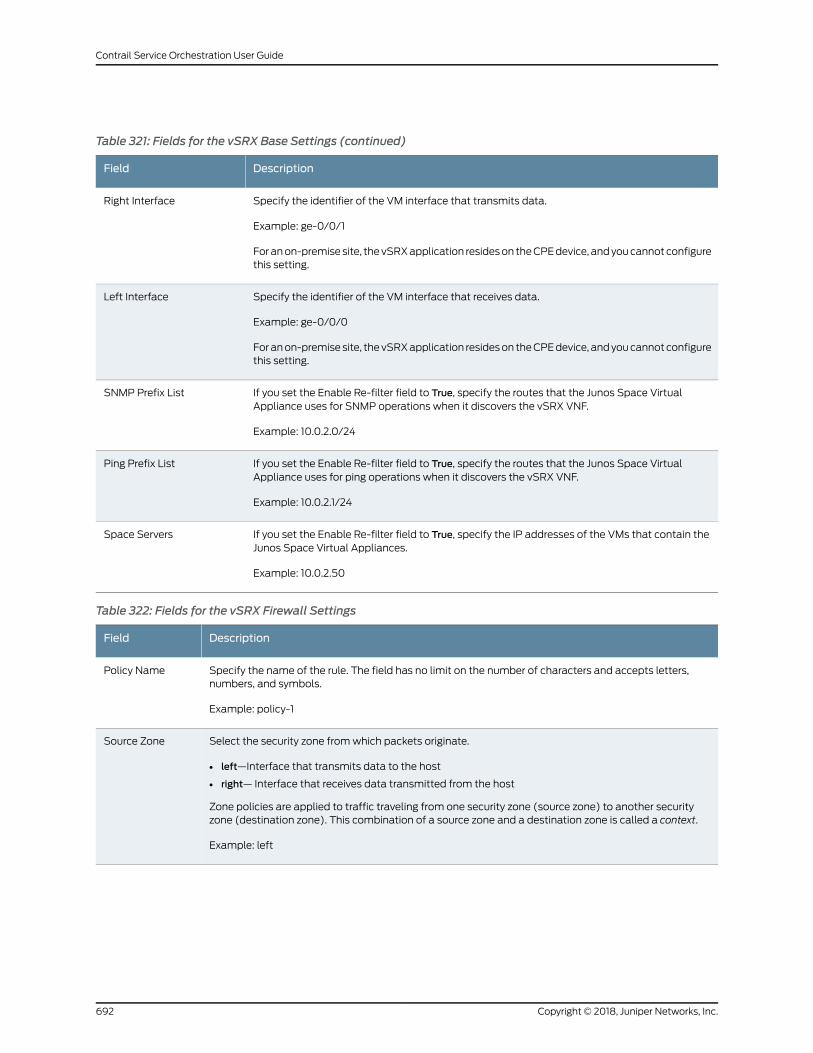
Table 321: Fields for the vSRX Base Settings (continued)
DescriptionField
Specify the identifier of the VM interface that transmits data.
Example: ge-0/0/1
Foranon-premisesite, thevSRXapplication resideson theCPEdevice, andyoucannotconfigurethis setting.
Right Interface
Specify the identifier of the VM interface that receives data.
Example: ge-0/0/0
Foranon-premisesite, thevSRXapplication resideson theCPEdevice, andyoucannotconfigurethis setting.
Left Interface
If you set the Enable Re-filter field to True, specify the routes that the Junos Space VirtualAppliance uses for SNMP operations when it discovers the vSRX VNF.
Example: 10.0.2.0/24
SNMP Prefix List
If you set the Enable Re-filter field to True, specify the routes that the Junos Space VirtualAppliance uses for ping operations when it discovers the vSRX VNF.
Example: 10.0.2.1/24
Ping Prefix List
If you set the Enable Re-filter field to True, specify the IP addresses of the VMs that contain theJunos Space Virtual Appliances.
Example: 10.0.2.50
Space Servers
Table 322: Fields for the vSRX Firewall Settings
DescriptionField
Specify the name of the rule. The field has no limit on the number of characters and accepts letters,numbers, and symbols.
Example: policy-1
Policy Name
Select the security zone fromwhich packets originate.
• left—Interface that transmits data to the host
• right— Interface that receives data transmitted from the host
Zone policies are applied to traffic traveling from one security zone (source zone) to another securityzone (destination zone). This combination of a source zone and a destination zone is called a context.
Example: left
Source Zone
Copyright © 2018, Juniper Networks, Inc.692
Contrail Service Orchestration User Guide
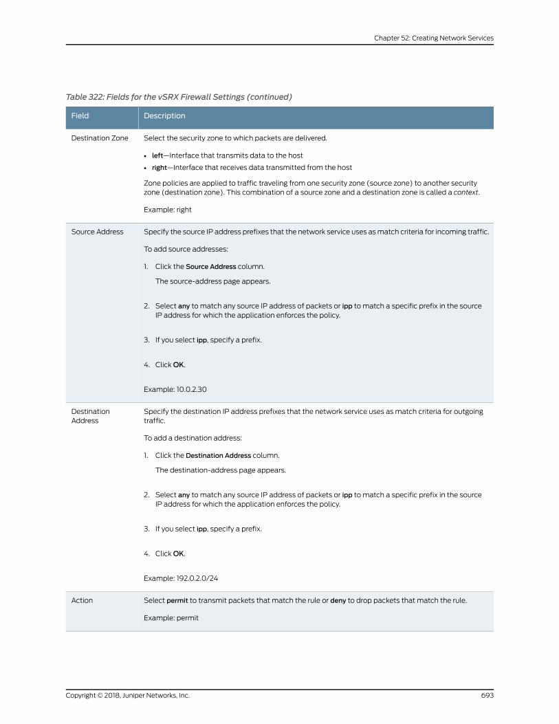
Table 322: Fields for the vSRX Firewall Settings (continued)
DescriptionField
Select the security zone to which packets are delivered.
• left—Interface that transmits data to the host
• right—Interface that receives data transmitted from the host
Zone policies are applied to traffic traveling from one security zone (source zone) to another securityzone (destination zone). This combination of a source zone and a destination zone is called a context.
Example: right
Destination Zone
Specify the source IP address prefixes that the network service uses asmatch criteria for incoming traffic.
To add source addresses:
1. Click the Source Address column.
The source-address page appears.
2. Select any to match any source IP address of packets or ipp to match a specific prefix in the sourceIP address for which the application enforces the policy.
3. If you select ipp, specify a prefix.
4. ClickOK.
Example: 10.0.2.30
Source Address
Specify the destination IP address prefixes that the network service uses as match criteria for outgoingtraffic.
To add a destination address:
1. Click the Destination Address column.
The destination-address page appears.
2. Select any to match any source IP address of packets or ipp to match a specific prefix in the sourceIP address for which the application enforces the policy.
3. If you select ipp, specify a prefix.
4. ClickOK.
Example: 192.0.2.0/24
DestinationAddress
Select permit to transmit packets that match the rule or deny to drop packets that match the rule.
Example: permit
Action
693Copyright © 2018, Juniper Networks, Inc.
Chapter 52: Creating Network Services
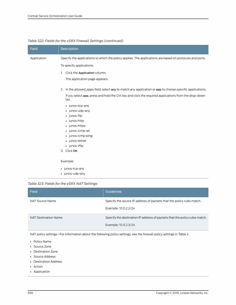
Table 322: Fields for the vSRX Firewall Settings (continued)
DescriptionField
Specify the applications to which the policy applies. The applications are based on protocols and ports.
To specify applications:
1. Click the Application column.
The application page appears.
2. In the allowed_apps field, select any to match any application or app to choose specific applications.
If you select app, press and hold the Ctrl key and click the required applications from the drop-downlist.
• junos-tcp-any
• junos-udp-any
• junos-ftp
• junos-http
• junos-https
• junos-icmp-all
• junos-icmp-ping
• junos-telnet
• junos-tftp
3. ClickOK.
Example:
• junos-tcp-any
• junos-udp-any
Application
Table 323: Fields for the vSRX NAT Settings
GuidelinesField
Specify the source IP address of packets that the policy rules match.
Example: 10.0.2.2/24
NAT Source Name
Specify the destination IP address of packets that the policy rulesmatch.
Example: 10.0.2.3/24
NAT Destination Name
NAT policy settings—For information about the following policy settings, see the firewall policy settings in Table 2.
• Policy Name
• Source Zone
• Destination Zone
• Source Address
• Destination Address
• Action
• Application
Copyright © 2018, Juniper Networks, Inc.694
Contrail Service Orchestration User Guide
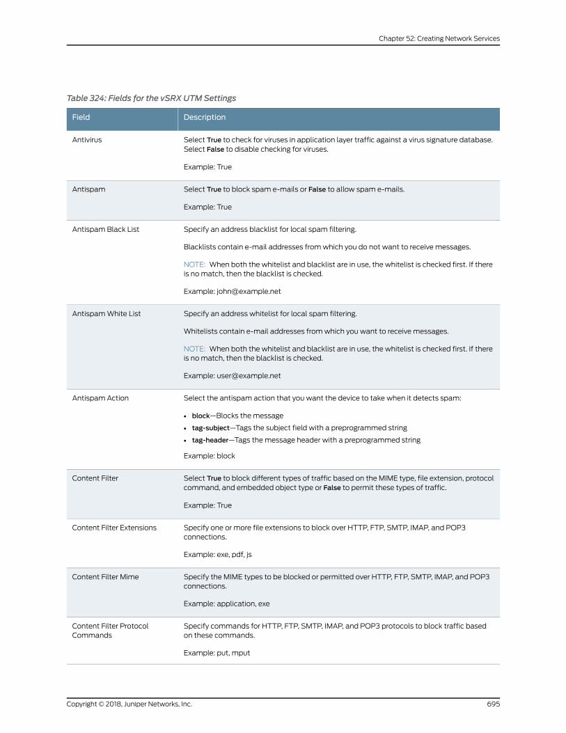
Table 324: Fields for the vSRX UTMSettings
DescriptionField
Select True to check for viruses in application layer traffic against a virus signature database.Select False to disable checking for viruses.
Example: True
Antivirus
Select True to block spam e-mails or False to allow spam e-mails.
Example: True
Antispam
Specify an address blacklist for local spam filtering.
Blacklists contain e-mail addresses fromwhich you do not want to receive messages.
NOTE: When both the whitelist and blacklist are in use, the whitelist is checked first. If thereis nomatch, then the blacklist is checked.
Example: [email protected]
Antispam Black List
Specify an address whitelist for local spam filtering.
Whitelists contain e-mail addresses fromwhich you want to receive messages.
NOTE: When both the whitelist and blacklist are in use, the whitelist is checked first. If thereis nomatch, then the blacklist is checked.
Example: [email protected]
AntispamWhite List
Select the antispam action that you want the device to take when it detects spam:
• block—Blocks the message
• tag-subject—Tags the subject field with a preprogrammed string
• tag-header—Tags themessage header with a preprogrammed string
Example: block
Antispam Action
Select True to block different types of traffic based on the MIME type, file extension, protocolcommand, and embedded object type or False to permit these types of traffic.
Example: True
Content Filter
Specify one or more file extensions to block over HTTP, FTP, SMTP, IMAP, and POP3connections.
Example: exe, pdf, js
Content Filter Extensions
Specify the MIME types to be blocked or permitted over HTTP, FTP, SMTP, IMAP, and POP3connections.
Example: application, exe
Content Filter Mime
Specify commands for HTTP, FTP, SMTP, IMAP, and POP3 protocols to block traffic basedon these commands.
Example: put, mput
Content Filter ProtocolCommands
695Copyright © 2018, Juniper Networks, Inc.
Chapter 52: Creating Network Services
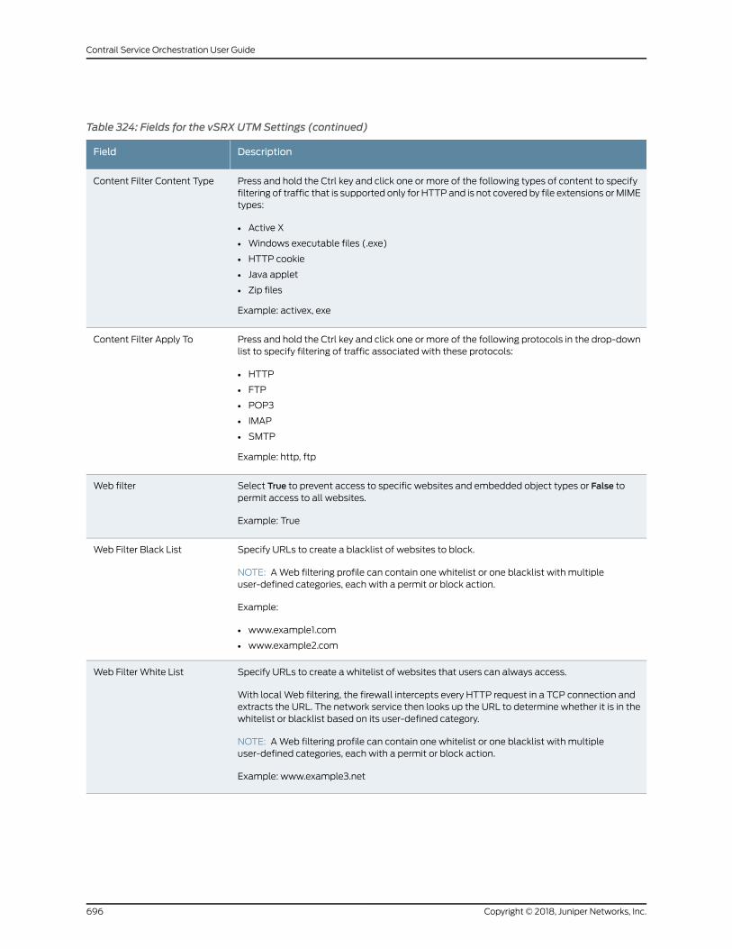
Table 324: Fields for the vSRX UTMSettings (continued)
DescriptionField
Press and hold the Ctrl key and click one or more of the following types of content to specifyfiltering of traffic that is supported only for HTTP and is not covered by file extensions orMIMEtypes:
• Active X
• Windows executable files (.exe)
• HTTP cookie
• Java applet
• Zip files
Example: activex, exe
Content Filter Content Type
Press and hold the Ctrl key and click one or more of the following protocols in the drop-downlist to specify filtering of traffic associated with these protocols:
• HTTP
• FTP
• POP3
• IMAP
• SMTP
Example: http, ftp
Content Filter Apply To
Select True to prevent access to specific websites and embedded object types or False topermit access to all websites.
Example: True
Web filter
Specify URLs to create a blacklist of websites to block.
NOTE: AWeb filtering profile can contain one whitelist or one blacklist with multipleuser-defined categories, each with a permit or block action.
Example:
• www.example1.com
• www.example2.com
Web Filter Black List
Specify URLs to create a whitelist of websites that users can always access.
With local Web filtering, the firewall intercepts every HTTP request in a TCP connection andextracts the URL. The network service then looks up the URL to determine whether it is in thewhitelist or blacklist based on its user-defined category.
NOTE: AWeb filtering profile can contain one whitelist or one blacklist with multipleuser-defined categories, each with a permit or block action.
Example: www.example3.net
Web Filter White List
Copyright © 2018, Juniper Networks, Inc.696
Contrail Service Orchestration User Guide
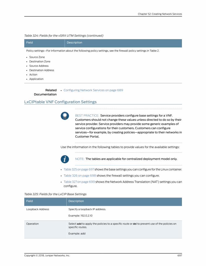
Table 324: Fields for the vSRX UTMSettings (continued)
DescriptionField
Policy settings—For information about the following policy settings, see the firewall policy settings in Table 2.
• Source Zone
• Destination Zone
• Source Address
• Destination Address
• Action
• Application
RelatedDocumentation
Configuring Network Services on page 689•
LxCIPtable VNF Configuration Settings
BEST PRACTICE: Service providers configure base settings for a VNF.Customers should not change these values unless directed to do so by theirservice provider. Service providers may provide some generic examples ofservice configurations for their customers. Customers can configureservices—for example, by creating policies—appropriate to their networks inCustomer Portal.
Use the information in the following tables to provide values for the available settings:
NOTE: The tables are applicable for centralized deploymentmodel only.
• Table325onpage697showsthebasesettingsyoucanconfigure for theLinuxcontainer.
• Table 326 on page 698 shows the firewall settings you can configure.
• Table 327 onpage699 shows theNetworkAddress Translation (NAT) settings you can
configure.
Table 325: Fields for the LxCIP Base Settings
DescriptionField
Specify a loopback IP address.
Example: 192.0.2.10
Loopback Address
Select add to apply the policies to a specific route or del to prevent use of the policies onspecific routes.
Example: add
Operation
697Copyright © 2018, Juniper Networks, Inc.
Chapter 52: Creating Network Services
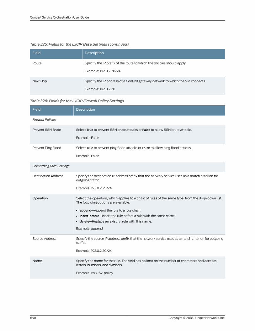
Table 325: Fields for the LxCIP Base Settings (continued)
DescriptionField
Specify the IP prefix of the route to which the policies should apply.
Example: 192.0.2.20/24
Route
Specify the IP address of a Contrail gateway network to which the VM connects.
Example: 192.0.2.20
Next Hop
Table 326: Fields for the LxCIP Firewall Policy Settings
DescriptionField
Firewall Policies
Select True to prevent SSH brute attacks or False to allow SSH brute attacks.
Example: False
Prevent SSH Brute
Select True to prevent ping flood attacks or False to allow ping flood attacks.
Example: False
Prevent Ping Flood
Forwarding Rule Settings
Specify the destination IP address prefix that the network service uses as amatch criterion foroutgoing traffic.
Example: 192.0.2.25/24
Destination Address
Select the operation, which applies to a chain of rules of the same type, from the drop-down list.The following options are available:
• append—Append the rule to a rule chain.
• insert-before—Insert the rule before a rule with the same name.
• delete—Replace an existing rule with this name.
Example: append
Operation
Specify the source IP address prefix that the network service uses as amatch criterion for outgoingtraffic.
Example: 192.0.2.20/24
Source Address
Specify the name for the rule. The field has no limit on the number of characters and acceptsletters, numbers, and symbols.
Example: vsrx-fw-policy
Name
Copyright © 2018, Juniper Networks, Inc.698
Contrail Service Orchestration User Guide
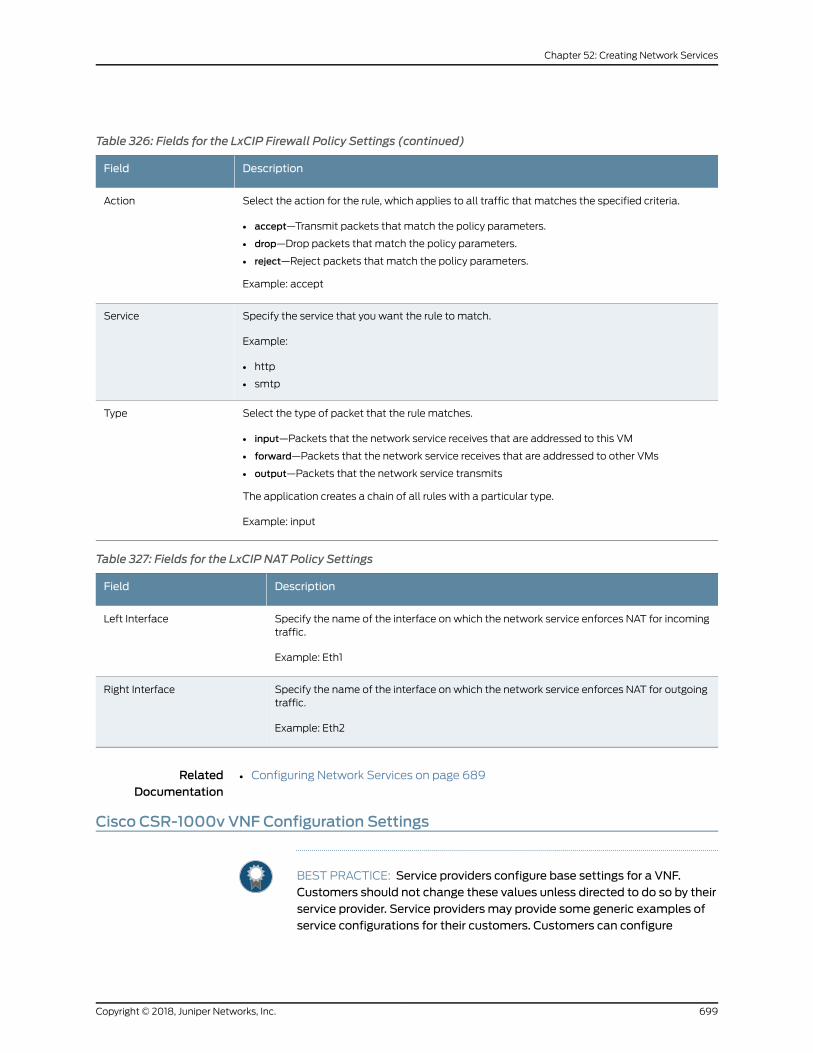
Table 326: Fields for the LxCIP Firewall Policy Settings (continued)
DescriptionField
Select the action for the rule, which applies to all traffic that matches the specified criteria.
• accept—Transmit packets that match the policy parameters.
• drop—Drop packets that match the policy parameters.
• reject—Reject packets that match the policy parameters.
Example: accept
Action
Specify the service that you want the rule to match.
Example:
• http
• smtp
Service
Select the type of packet that the rule matches.
• input—Packets that the network service receives that are addressed to this VM
• forward—Packets that the network service receives that are addressed to other VMs
• output—Packets that the network service transmits
The application creates a chain of all rules with a particular type.
Example: input
Type
Table 327: Fields for the LxCIP NAT Policy Settings
DescriptionField
Specify the name of the interface on which the network service enforces NAT for incomingtraffic.
Example: Eth1
Left Interface
Specify the name of the interface on which the network service enforces NAT for outgoingtraffic.
Example: Eth2
Right Interface
RelatedDocumentation
Configuring Network Services on page 689•
Cisco CSR-1000v VNF Configuration Settings
BEST PRACTICE: Service providers configure base settings for a VNF.Customers should not change these values unless directed to do so by theirservice provider. Service providers may provide some generic examples ofservice configurations for their customers. Customers can configure
699Copyright © 2018, Juniper Networks, Inc.
Chapter 52: Creating Network Services
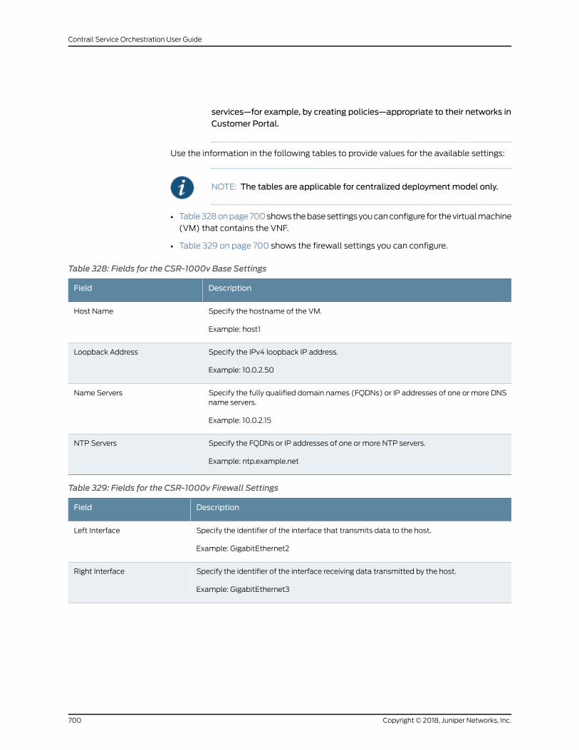
services—for example, by creating policies—appropriate to their networks inCustomer Portal.
Use the information in the following tables to provide values for the available settings:
NOTE: The tables are applicable for centralized deploymentmodel only.
• Table328onpage700showsthebasesettingsyoucanconfigure for thevirtualmachine
(VM) that contains the VNF.
• Table 329 on page 700 shows the firewall settings you can configure.
Table 328: Fields for the CSR-1000v Base Settings
DescriptionField
Specify the hostname of the VM.
Example: host1
Host Name
Specify the IPv4 loopback IP address.
Example: 10.0.2.50
Loopback Address
Specify the fully qualified domain names (FQDNs) or IP addresses of one or more DNSname servers.
Example: 10.0.2.15
Name Servers
Specify the FQDNs or IP addresses of one or more NTP servers.
Example: ntp.example.net
NTP Servers
Table 329: Fields for the CSR-1000v Firewall Settings
DescriptionField
Specify the identifier of the interface that transmits data to the host.
Example: GigabitEthernet2
Left Interface
Specify the identifier of the interface receiving data transmitted by the host.
Example: GigabitEthernet3
Right Interface
Copyright © 2018, Juniper Networks, Inc.700
Contrail Service Orchestration User Guide
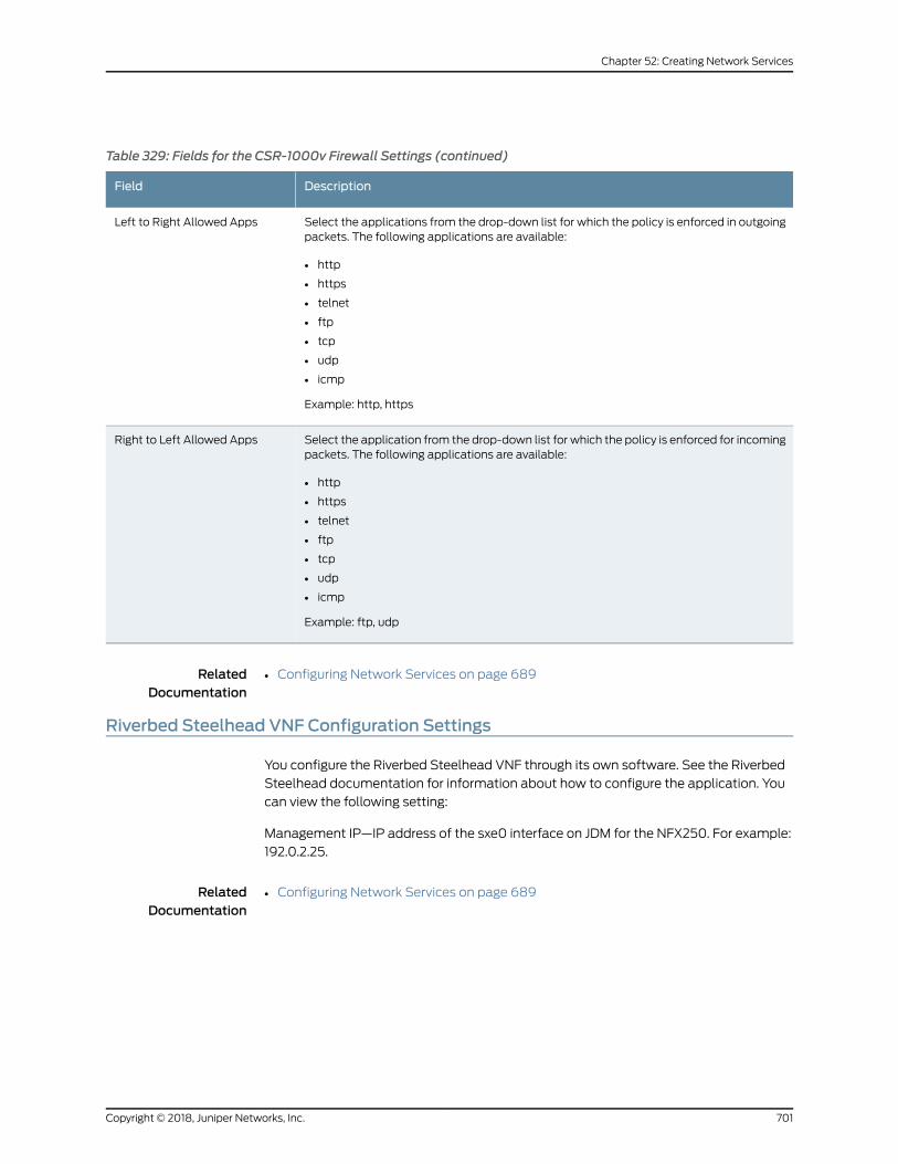
Table 329: Fields for the CSR-1000v Firewall Settings (continued)
DescriptionField
Select the applications from the drop-down list for which the policy is enforced in outgoingpackets. The following applications are available:
• http
• https
• telnet
• ftp
• tcp
• udp
• icmp
Example: http, https
Left to Right Allowed Apps
Select the application from the drop-down list for which the policy is enforced for incomingpackets. The following applications are available:
• http
• https
• telnet
• ftp
• tcp
• udp
• icmp
Example: ftp, udp
Right to Left Allowed Apps
RelatedDocumentation
Configuring Network Services on page 689•
Riverbed Steelhead VNF Configuration Settings
You configure the Riverbed Steelhead VNF through its own software. See the Riverbed
Steelhead documentation for information about how to configure the application. You
can view the following setting:
Management IP—IP address of the sxe0 interface on JDM for the NFX250. For example:
192.0.2.25.
RelatedDocumentation
• Configuring Network Services on page 689
701Copyright © 2018, Juniper Networks, Inc.
Chapter 52: Creating Network Services

Copyright © 2018, Juniper Networks, Inc.702
Contrail Service Orchestration User Guide
CHAPTER 53
Managing Network Services
• About the Designs Page for the Network Service Designer on page 703
• Publishing Network Service Designs on page 704
• Copying Network Service Designs on page 705
• Editing Network Service Designs on page 705
• Deleting Network Service Designs on page 706
• Viewing Network Service Designs on page 707
About the Designs Page for the Network Service Designer
To access this page, click Home> Designs.
Use the Designs page to view andmanage the network service design templates that
you have saved or published.
Tasks You Can Perform
You can perform the following tasks from this page:
• Publish a network service design template to the network service catalog. See
“Publishing Network Service Designs” on page 704
• Editing a network service design template. See “Editing Network Service Designs” on
page 705
• Delete one or more network service designs. See “Deleting Network Service Designs”
on page 706
• Copy one ormore network service designs. See “Copying Network Service Designs” on
page 705
• View complete details of a network service design. See “Viewing Network Service
Designs” on page 707
Field Descriptions
Table 330onpage 704provides guidelines onusing the fields on theDesignspage for the
Network Service Designer.
703Copyright © 2018, Juniper Networks, Inc.
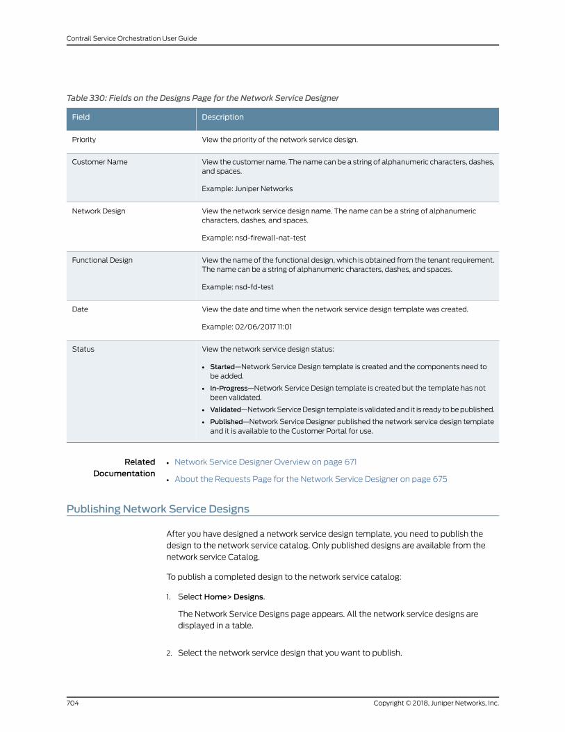
Table 330: Fields on the Designs Page for the Network Service Designer
DescriptionField
View the priority of the network service design.Priority
View the customer name. The name can be a string of alphanumeric characters, dashes,and spaces.
Example: Juniper Networks
Customer Name
View the network service design name. The name can be a string of alphanumericcharacters, dashes, and spaces.
Example: nsd-firewall-nat-test
Network Design
View the name of the functional design, which is obtained from the tenant requirement.The name can be a string of alphanumeric characters, dashes, and spaces.
Example: nsd-fd-test
Functional Design
View the date and time when the network service design template was created.
Example: 02/06/2017 11:01
Date
View the network service design status:
• Started—Network Service Design template is created and the components need tobe added.
• In-Progress—Network Service Design template is created but the template has notbeen validated.
• Validated—NetworkServiceDesign template is validatedand it is ready tobepublished.
• Published—Network Service Designer published the network service design templateand it is available to the Customer Portal for use.
Status
RelatedDocumentation
Network Service Designer Overview on page 671•
• About the Requests Page for the Network Service Designer on page 675
Publishing Network Service Designs
After you have designed a network service design template, you need to publish the
design to the network service catalog. Only published designs are available from the
network service Catalog.
To publish a completed design to the network service catalog:
1. Select Home> Designs.
The Network Service Designs page appears. All the network service designs are
displayed in a table.
2. Select the network service design that you want to publish.
Copyright © 2018, Juniper Networks, Inc.704
Contrail Service Orchestration User Guide
The status of the template isValidated. For published designs, the status isPublished.
3. Select Publish from the Edit drop-down list.
Your network service design is published and available to be used by the network
service catalog. Its status changes from Validated to Published.
RelatedDocumentation
About the Designs Page for the Network Service Designer on page 703•
Copying Network Service Designs
You can create a new network service design template by copying an existing design
template and editing it.
To copy one or more designs that you have saved or published:
1. Select Home> Designs.
The Network Service Designs page appears. All the network service designs are
displayed in a table.
2. Select the network service design that you want to copy and click Copy NSD.
A page requesting confirmation for the copying appears.
3. Click Yes to confirm that you want to copy the designs.
The additional services appear in the table with the status as Validated.
RelatedDocumentation
About the Designs Page for the Network Service Designer on page 703•
Editing Network Service Designs
To edit a network service design that you have saved or published:
1. View the network service design on the Build page.
If the design is not currently visible on the Build page:
a. Click Home in the toolbar and Designs in the left navigation bar.
The list of saved and published designs appears.
b. Click Edit for the network service you want to configure.
The Build page appears, displaying the network service design.
2. Click Function Configuration at the right of the Build page.
705Copyright © 2018, Juniper Networks, Inc.
Chapter 53: Managing Network Services
The Service page appears, displaying the VNFs in the service chain and the Base
Configure tab for the first VNF in the Functional Service Design workspace.
3. Specify the settings on the Base Configure tab.
This action configures the VM in which the VNF resides.
BEST PRACTICE: Complete all the settings on the Base Configure tab tooptimize the Cloud CPE solution. End users can see these settings inCustomer Portal and should not override them.
4. (Optional) Specify settings on the other tabs for this VNF to customize a particular
function such as Network Address Translation (NAT).
End users can customize their own services with these settings in Customer Portal.
Settings that end users specify in Customer Portal override conflicting settings that
you specify in Network Service Designer.
5. Click the next VNF icon in the Configuration page.
6. Repeat Step 3 and Step 4.
7. Repeat Steps 5 through 7 for each VNF in the chain.
8. ClickOK.
The Service page closes.
RelatedDocumentation
About the Designs Page for the Network Service Designer on page 703•
Deleting Network Service Designs
To delete a network service design:
1. Select Home>Designs.
The Designs page appears.
2. Select the network service design that you want to delete.
3. Click Delete.
A page requesting confirmation for the deletion appears.
4. Click Yes to confirm that you want to delete the design.
Copyright © 2018, Juniper Networks, Inc.706
Contrail Service Orchestration User Guide
The network service design is deleted.
To delete multiple designs that you have saved or published:
1. From the list of designs, select the designs that you want to delete.
2. Click Delete NSD.
A page requesting confirmation for the deletion appears.
3. Click Yes to confirm that you want to delete the designs.
The designs are deleted and are then displayed on the Requests Page.
RelatedDocumentation
About the Designs Page for the Network Service Designer on page 703•
Viewing Network Service Designs
You can view the network service design in grid view and tree view. The default option is
grid view.
To view the network service designs that you have saved or published:
1. Select Home> Designs.
The Network Service Designs page appears. All the network service designs are
displayed in a table.
2. Click ShowDetails.
The network service designs are categorized according to their status and listed in
the Home page.
3. Select a network service design template to view the detailed information about the
design template, such as customer information, resource requirements, network
design, and functional design.
You can edit, publish, or delete a network service design from this view.
RelatedDocumentation
• About the Designs Page for the Network Service Designer on page 703
707Copyright © 2018, Juniper Networks, Inc.
Chapter 53: Managing Network Services

Copyright © 2018, Juniper Networks, Inc.708
Contrail Service Orchestration User Guide
PART 4
Service and Infrastructure Monitor
• Service and Infrastructure Monitor introduction on page 711
• Monitoring Activities in the Deployment on page 713
709Copyright © 2018, Juniper Networks, Inc.

Copyright © 2018, Juniper Networks, Inc.710
Contrail Service Orchestration User Guide
CHAPTER 54
Service and Infrastructure Monitorintroduction
• Service and Infrastructure Monitor Overview on page 711
• Accessing the Service and Infrastructure Monitor GUI on page 712
Service and Infrastructure Monitor Overview
Serviceand InfrastructureMonitor (SIM)operateswith the third-partymonitoringsoftware
Icinga to provide complete monitoring and troubleshooting of Contrail Service
Orchestration.
When you install Contrail Service Orchestration, an Icinga agent is installed on servers
and virtual machines (VMs), which enables Icinga to monitor data on:
• Physical servers
• VMs that host virtualized network functions (VNFs)
• VMs that host microservices
Service and Infrastructure Monitor collects events frommicroservices in Contrail Service
Orchestration, and correlates the events to provide information about network service,
their component VNFs, and the VMs that host the VNFs.
All data is presented through the IcingaGUI. You use theGUI to obtain both a quick visual
displayofContrail ServiceOrchestrationstatusandmoredetailed listsof eventmessages.
Coloredsquares,whichmaycontainnumbers, in theGUIprovideavisual statusofContrail
Service Orchestration network.
• A green square indicates the number of items that are working correctly.
• A yellow square indicates the number of items with potential problems to investigate.
• A red square indicates the number of items that are not working.
• A purple square indicates the number of items with a failed connection.
The following options in the left navigation pane of the Icinga GUI are customized for
Contrail Service Orchestration:
711Copyright © 2018, Juniper Networks, Inc.
• Dashboard
• Network Services
• Infrastructure
Other features in the Icinga GUI are not customized and appear in the standard Icinga
GUI.
Use this Service and Infrastructure Monitor documentation for information about using
the customized options in the GUI. See the Icinga documentation for a general overview
of the GUI and information about all non-customized features.
RelatedDocumentation
Monitoring Network Services on page 713•
• MonitoringVNFsUsed inNetworkServicesand theVMsThatHost theVNFsonpage714
• Monitoring Microservices on page 717
• Monitoring Microservices and Their Host VMs on page 718
• Monitoring Physical Servers on page 720
Accessing the Service and Infrastructure Monitor GUI
To access the GUI for Service and Infrastructure Monitor:
1. Using a web browser, access the URL for Service and Infrastructure Monitor:
http://central-IP-Address:1947/icingaweb2
central-IP-Address—IP address of the server or VM that hosts the microservices for
the central point of presence (POP)
For example:
http://192.0.2.1:1947/icingaweb2
2. Log in with the username icinga and encrypted password.
RelatedDocumentation
• Service and Infrastructure Monitor Overview on page 711
Copyright © 2018, Juniper Networks, Inc.712
Contrail Service Orchestration User Guide
CHAPTER 55
Monitoring Activities in the Deployment
• Monitoring Network Services on page 713
• MonitoringVNFsUsed inNetworkServicesand theVMsThatHost theVNFsonpage714
• Monitoring Microservices on page 717
• Monitoring Microservices and Their Host VMs on page 718
• Monitoring Physical Servers on page 720
Monitoring Network Services
Service and Infrastructure Monitor displays information about network services running
in the deployment. This information is related to the Network Service Overview on the
dashboard, which displays information about component VNFs of network services and
theVMs inwhich theVNFs reside. In this view, however, the focus is on theactual network
service rather than its component VNFs and the VMs in which they reside.
Tomonitor network services:
1. In the left navigation pane, click Network Services.
Serviceand InfrastructureMonitordisplaysanarrayofnetwork servicesandmonitoring
parameters.
2. In the array, hover over an entry to see additional information for the entry.
3. Click a colored square to see detailed information for the entry.
Table 331 on page 713 shows themeaning of the monitoring parameters for network
services.
Table 331: Parameters for Monitoring Network Services
MeaningParameter
Name of the network service.Network Service
713Copyright © 2018, Juniper Networks, Inc.
Table 331: Parameters for Monitoring Network Services (continued)
MeaningParameter
State of the network service and the time it entered that state.
• Up—operational
• Down—not operational
Network Service status
Number of VNFs in the service chain.Num of Network Functions
Number of network functions in a colored square that indicates the status of the instance.When you click the square you see:
• An entry for each VNF in the service chain.
• The status of the host in which the VNF resides.
• The IP address of the host in which the VNF resides.
• The name of the VNF.
• The result from the last ping the Icinga agent sent to the host, including any loss of packets,and the round trip average (RTA) travel time.
Network Function
Total numberof commands issued tomonitor thestatusof thenetwork service since it becameoperational.
Commands
Result of the commands issued to monitor the status of the network service. When you clickthe square you see:
• A list of parameters for a specific network function and its host.
• The state of the parameter and how long the parameter has been in that state.
• Additional details about the state of the host.
Command Status
RelatedDocumentation
MonitoringVNFsUsed inNetworkServicesand theVMsThatHost theVNFsonpage714•
Monitoring VNFs Used in Network Services and the VMs That Host the VNFs
On the dashboard, the Network Service Overview provides information about the VNFs
used innetwork servicesand theVMs thathost thoseVNFs.Youcanalsoview information
about the component VNFs in a network service by clicking Monitor Network Services in
the left navigation bar.
To view information about VNFs used in network services and the VMs that host the
VNFs:
1. In the left navigation bar, click Dashboard.
The dashboard appears, displaying several arrays of information.
2. (Optional) In the Network Services Overview array, hover over a colored square in the
array to see the latest event message for a specific parameter and host.
Copyright © 2018, Juniper Networks, Inc.714
Contrail Service Orchestration User Guide
3. (Optional) In the Network Services Overview array, click a colored square to see
detailed information for a specific parameter and host.
4. (Optional) In the Network Services Overview array, click an IP address to view all the
event messages for a host.
5. (Optional) In the Network Services Overview array, click a parameter name to view
event messages on all hosts for that parameter.
See Table 332 on page 715 for information about the monitoring parameters used for
VNFs and the VMs that host them.
Table 332: Parameters for Monitoring VNFs and Their Host VMs
MeaningParameter
Rate of traffic entering the interface that transmits data to the host.left_net_interface_input_pckt_rate
Rate of traffic leaving the interface that transmits data to the host.left_net_interface_output_pckt_rate
State of the interface that transmits data to the network host.
• Up—operational
• Down—not operational
left_net_interface_stats
State of the interface to which the host transmits data.
• Up—operational
• Down—not operational
right_net_interface1_stats
Rate of traffic entering the interface to which the host transmits data.right_net_interface_input_packet_rate
Rate of traffic leaving the interface to which the host transmits data.right_net_interface_output_packet_rate
Percentage of the Routing Engine’s control planememory that VM is using.routing_engine_ctrlplane_memusage
Mean percentage of available load capacity used by the Routing Engine’s controlplane.
routing_engine_load_average
Percentage of available CPU capacity used by the Routing Engine’s control plane.routing_engine_system_cpu
Number of active sessions of the VNF compared to the maximum number ofsessions allowed.
<VNF>_activesessions
Number of sessions of the VNF that VNF Manager failed to activate.<VNF>_failedsessions
Number of sessionsadded (ramp-up rate) for the last60seconds. The valuedoesnot display the total number of sessions or the number of deleted sessions.
<VNF>_performance_session
Servicesprocessingunit (SPU), percentageofCPUcapacity that handles thedataplane for the security service.
<VNF>_performance_spu
715Copyright © 2018, Juniper Networks, Inc.
Chapter 55: Monitoring Activities in the Deployment
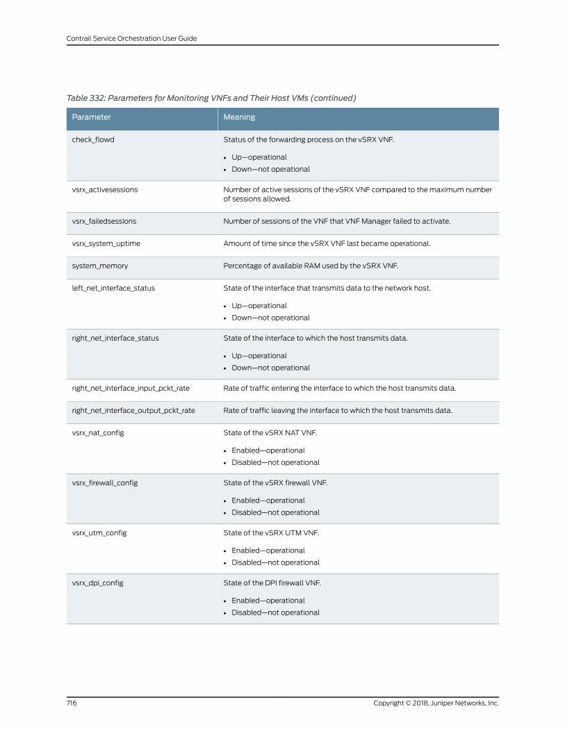
Table 332: Parameters for Monitoring VNFs and Their Host VMs (continued)
MeaningParameter
Status of the forwarding process on the vSRX VNF.
• Up—operational
• Down—not operational
check_flowd
Number of active sessions of the vSRX VNF compared to the maximum numberof sessions allowed.
vsrx_activesessions
Number of sessions of the VNF that VNF Manager failed to activate.vsrx_failedsessions
Amount of time since the vSRX VNF last became operational.vsrx_system_uptime
Percentage of available RAM used by the vSRX VNF.system_memory
State of the interface that transmits data to the network host.
• Up—operational
• Down—not operational
left_net_interface_status
State of the interface to which the host transmits data.
• Up—operational
• Down—not operational
right_net_interface_status
Rate of traffic entering the interface to which the host transmits data.right_net_interface_input_pckt_rate
Rate of traffic leaving the interface to which the host transmits data.right_net_interface_output_pckt_rate
State of the vSRX NAT VNF.
• Enabled—operational
• Disabled—not operational
vsrx_nat_config
State of the vSRX firewall VNF.
• Enabled—operational
• Disabled—not operational
vsrx_firewall_config
State of the vSRX UTM VNF.
• Enabled—operational
• Disabled—not operational
vsrx_utm_config
State of the DPI firewall VNF.
• Enabled—operational
• Disabled—not operational
vsrx_dpi_config
Copyright © 2018, Juniper Networks, Inc.716
Contrail Service Orchestration User Guide
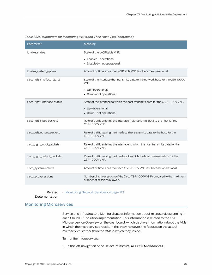
Table 332: Parameters for Monitoring VNFs and Their Host VMs (continued)
MeaningParameter
State of the LxCIPtable VNF.
• Enabled—operational
• Disabled—not operational
iptable_status
Amount of time since the LxCIPtable VNF last became operationaliptable_system_uptime
State of the interface that transmits data to the network host for the CSR-1000VVNF.
• Up—operational
• Down—not operational
cisco_left_interface_status
State of the interface to which the host transmits data for the CSR-1000V VNF.
• Up—operational
• Down—not operational
cisco_right_interface_status
Rate of traffic entering the interface that transmits data to the host for theCSR-1000V VNF.
cisco_left_input_packets
Rate of traffic leaving the interface that transmits data to the host for theCSR-1000V VNF.
cisco_left_output_packets
Rate of traffic entering the interface to which the host transmits data for theCSR-1000V VNF.
cisco_right_input_packets
Rate of traffic leaving the interface to which the host transmits data for theCSR-1000V VNF.
cisco_right_output_packets
Amount of time since the Cisco CSR-1000V VNF last became operational.cisco_system-uptime
Numberofactivesessionsof theCiscoCSR-1000VVNFcomparedto themaximumnumber of sessions allowed.
cisco_activesessions
RelatedDocumentation
Monitoring Network Services on page 713•
MonitoringMicroservices
Service and Infrastructure Monitor displays information about microservices running in
each Cloud CPE solution implementation. This information is related to the CSP
Microservervice Overview on the dashboard, which displays information about the VMs
in which the microservices reside. In this view, however, the focus is on the actual
microservice srather than the VMs in which they reside.
Tomonitor microservices:
1. In the left navigation pane, select Infrastructure > CSPMicroservices.
717Copyright © 2018, Juniper Networks, Inc.
Chapter 55: Monitoring Activities in the Deployment
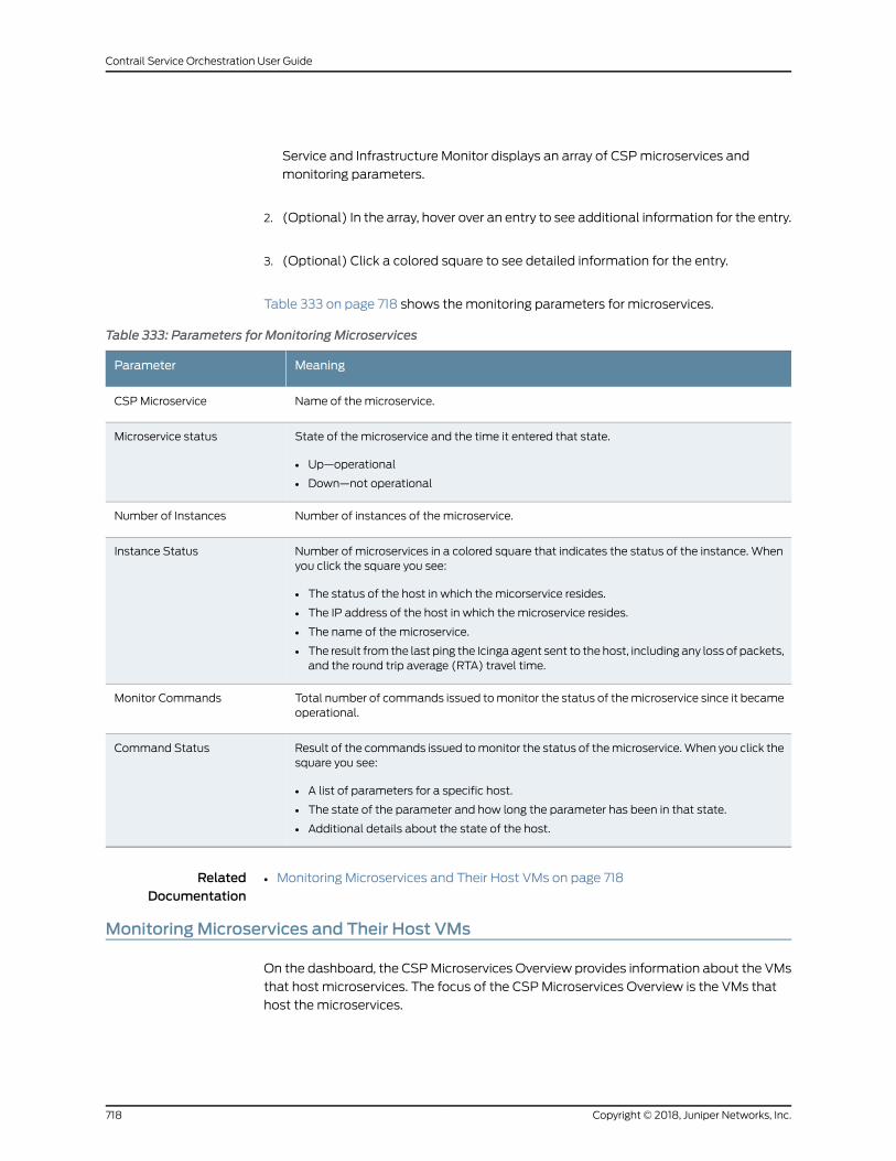
Service and Infrastructure Monitor displays an array of CSPmicroservices and
monitoring parameters.
2. (Optional) In the array, hover over an entry to see additional information for the entry.
3. (Optional) Click a colored square to see detailed information for the entry.
Table 333 on page 718 shows themonitoring parameters for microservices.
Table 333: Parameters for Monitoring Microservices
MeaningParameter
Name of the microservice.CSPMicroservice
State of the microservice and the time it entered that state.
• Up—operational
• Down—not operational
Microservice status
Number of instances of the microservice.Number of Instances
Number of microservices in a colored square that indicates the status of the instance. Whenyou click the square you see:
• The status of the host in which the micorservice resides.
• The IP address of the host in which the microservice resides.
• The name of the microservice.
• The result from the last ping the Icinga agent sent to the host, including any loss of packets,and the round trip average (RTA) travel time.
Instance Status
Total number of commands issued tomonitor the status of themicroservice since it becameoperational.
Monitor Commands
Result of the commands issued tomonitor the status of themicroservice.When you click thesquare you see:
• A list of parameters for a specific host.
• The state of the parameter and how long the parameter has been in that state.
• Additional details about the state of the host.
Command Status
RelatedDocumentation
Monitoring Microservices and Their Host VMs on page 718•
MonitoringMicroservices and Their Host VMs
On the dashboard, the CSPMicroservices Overview provides information about the VMs
that host microservices. The focus of the CSPMicroservices Overview is the VMs that
host the microservices.
Copyright © 2018, Juniper Networks, Inc.718
Contrail Service Orchestration User Guide
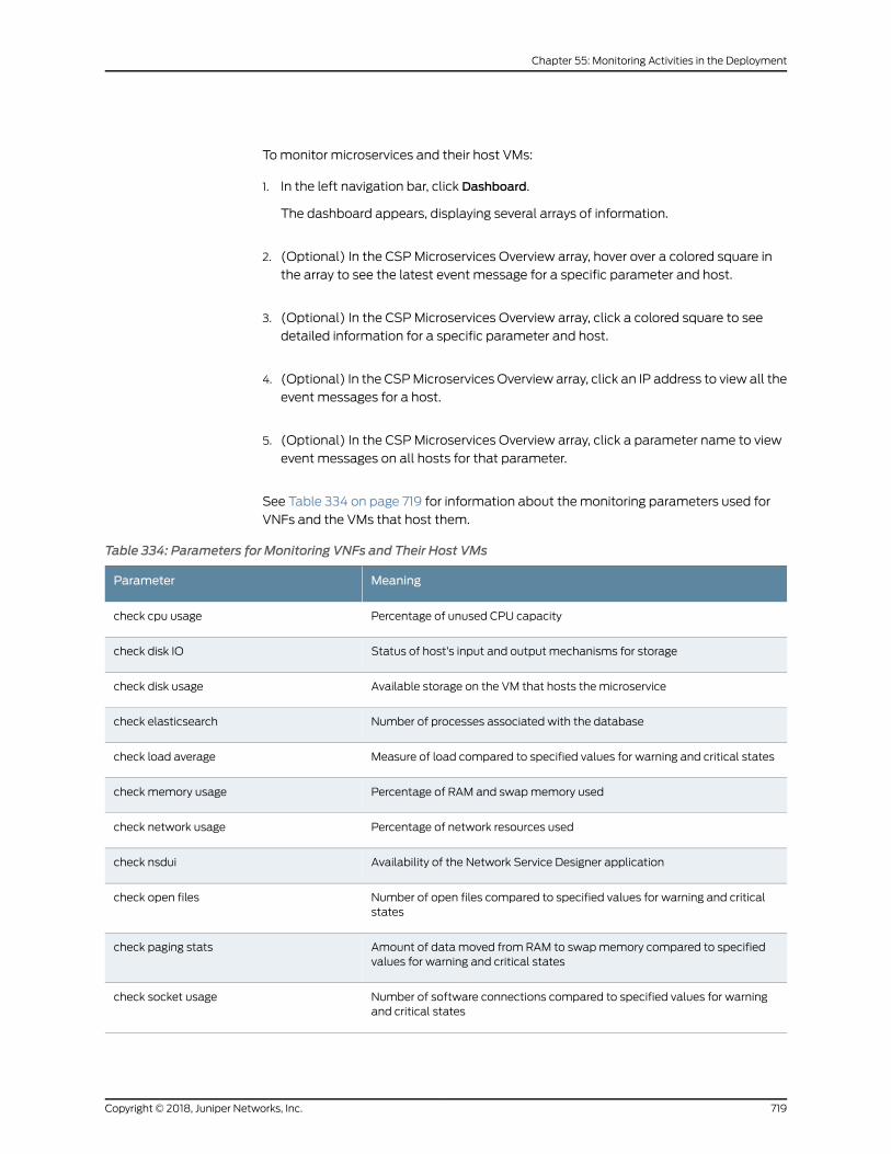
Tomonitor microservices and their host VMs:
1. In the left navigation bar, click Dashboard.
The dashboard appears, displaying several arrays of information.
2. (Optional) In the CSPMicroservices Overview array, hover over a colored square in
the array to see the latest event message for a specific parameter and host.
3. (Optional) In the CSPMicroservices Overview array, click a colored square to see
detailed information for a specific parameter and host.
4. (Optional) In the CSPMicroservices Overview array, click an IP address to view all the
event messages for a host.
5. (Optional) In the CSPMicroservices Overview array, click a parameter name to view
event messages on all hosts for that parameter.
See Table 334 on page 719 for information about the monitoring parameters used for
VNFs and the VMs that host them.
Table 334: Parameters for Monitoring VNFs and Their Host VMs
MeaningParameter
Percentage of unused CPU capacitycheck cpu usage
Status of host’s input and output mechanisms for storagecheck disk IO
Available storage on the VM that hosts the microservicecheck disk usage
Number of processes associated with the databasecheck elasticsearch
Measure of load compared to specified values for warning and critical statescheck load average
Percentage of RAM and swapmemory usedcheck memory usage
Percentage of network resources usedcheck network usage
Availability of the Network Service Designer applicationcheck nsdui
Number of open files compared to specified values for warning and criticalstates
check open files
Amount of data moved from RAM to swapmemory compared to specifiedvalues for warning and critical states
check paging stats
Number of software connections compared to specified values for warningand critical states
check socket usage
719Copyright © 2018, Juniper Networks, Inc.
Chapter 55: Monitoring Activities in the Deployment
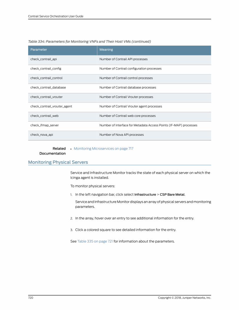
Table 334: Parameters for Monitoring VNFs and Their Host VMs (continued)
MeaningParameter
Number of Contrail API processescheck_contrail_api
Number of Contrail configuration processescheck_contrail_config
Number of Contrail control processescheck_contrail_control
Number of Contrail database processescheck_contrail_database
Number of Contrail Vrouter processescheck_contrail_vrouter
Number of Contrail Vrouter agent processescheck_contrail_vrouter_agent
Number of Contrail web core processescheck_contrail_web
Number of Interface for Metadata Access Points (IF-MAP) processescheck_ifmap_server
Number of Nova API processescheck_nova_api
RelatedDocumentation
Monitoring Microservices on page 717•
Monitoring Physical Servers
Service and Infrastructure Monitor tracks the state of each physical server on which the
Icinga agent is installed.
Tomonitor physical servers:
1. In the left navigation bar, click select Infrastructure > CSP BareMetal.
Serviceand InfrastructureMonitordisplaysanarrayofphysical serversandmonitoring
parameters.
2. In the array, hover over an entry to see additional information for the entry.
3. Click a colored square to see detailed information for the entry.
See Table 335 on page 721 for information about the parameters.
Copyright © 2018, Juniper Networks, Inc.720
Contrail Service Orchestration User Guide
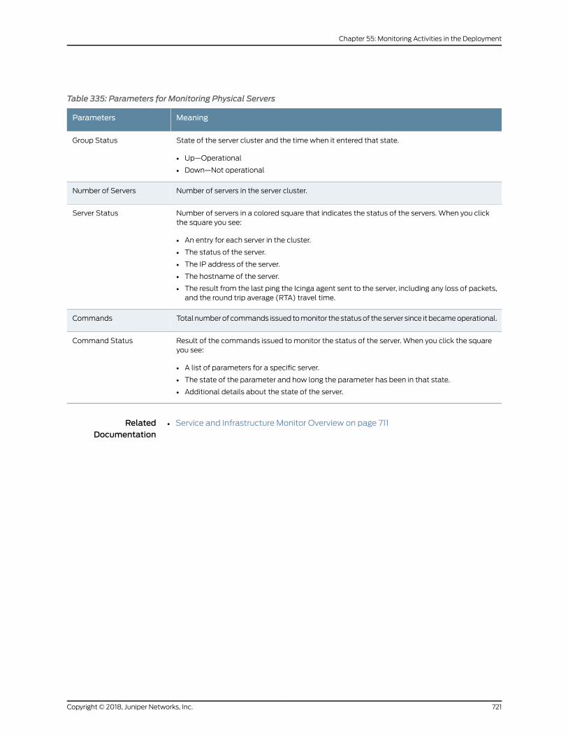
Table 335: Parameters for Monitoring Physical Servers
MeaningParameters
State of the server cluster and the time when it entered that state.
• Up—Operational
• Down—Not operational
Group Status
Number of servers in the server cluster.Number of Servers
Number of servers in a colored square that indicates the status of the servers. When you clickthe square you see:
• An entry for each server in the cluster.
• The status of the server.
• The IP address of the server.
• The hostname of the server.
• The result from the last ping the Icinga agent sent to the server, including any loss of packets,and the round trip average (RTA) travel time.
Server Status
Total numberof commands issued tomonitor thestatusof theserver since it becameoperational.Commands
Result of the commands issued to monitor the status of the server. When you click the squareyou see:
• A list of parameters for a specific server.
• The state of the parameter and how long the parameter has been in that state.
• Additional details about the state of the server.
Command Status
RelatedDocumentation
• Service and Infrastructure Monitor Overview on page 711
721Copyright © 2018, Juniper Networks, Inc.
Chapter 55: Monitoring Activities in the Deployment

Copyright © 2018, Juniper Networks, Inc.722
Contrail Service Orchestration User Guide