contract research report 419/2002 - health and … · contract research report 419/2002. hse health...
TRANSCRIPT

HSEHealth & Safety
Executive
Developing advisory softwareto comply with IEC-61508
Prepared by Adelardfor the Health and Safety Executive
CONTRACT RESEARCH REPORT
419/2002

HSEHealth & Safety
Executive
Developing advisory softwareto comply with IEC-61508
P Froome & C JonesAdelard
Drysdale BuildingNorthampton Square
London EC1V 0HBUnited Kingdom
This report gives constructive technical guidance on how to develop advisory software so as to achievecompliance with IEC 61508 “Functional safety of electrical/electronic/programmable electronic safety-related systems”.
This guidance defines the scope of a limited class of safety-related advisory software, explains in asoftware context what IEC 61508 is trying to achieve at each key point of the safety lifecycle.
Two practical illustrations are given of quality management procedures to collect compliance evidence.The first is a quality management system (QMS) which is 3rd party certified to ISO 9000-3. The secondrecognises that many software developers will not have a 3rd party certified QMS, and even fewerspecifically for software development.
This report and the work it describes were funded by the Health and Safety Executive (HSE). Itscontents, including any opinions and/or conclusions expressed, are those of the author alone and donot necessarily reflect HSE policy.
HSE BOOKS

ii
© Crown copyright 2002Applications for reproduction should be made in writing to:Copyright Unit, Her Majesty’s Stationery Office,St Clements House, 2-16 Colegate, Norwich NR3 1BQ
First published 2002
ISBN 0 7176 2304 1
All rights reserved. No part of this publication may bereproduced, stored in a retrieval system, or transmittedin any form or by any means (electronic, mechanical,photocopying, recording or otherwise) without the priorwritten permission of the copyright owner.

iii
FOREWORD
This report gives technical guidance to software developers on how to comply with IEC 61508, but solely for the limited class of safety-related advisory software. Explicitly excluded is software that has any degree of online control over machinery or plant. This guidance should be used in conjunction with IEC 61508.
It is recommended that developers familiarise themselves with “The Engineer’s Responsibility for Computer Based Decisions”, published by The Institution of Chemical Engineers, Geo. E. Davis Building, 165–171 Railway Terrace, Rugby, CV21 3HQ, UK.
The developer’s goal is to produce advisory software of demonstrable safety integrity, assessed on the basis of recorded evidence that the requirements of IEC 61508 have been met. An explicit quality management approach is recommended to facilitate the systematic gathering of compliance evidence to make possible the assessment of software safety integrity. The developer will need to develop suitable quality management procedures, or adapt existing procedures, to ensure that the evidence, illustrated in Appendices 1 and 2, is collected in a manner suitable for the assessment process.
HSE invites comments on the practicality and effectiveness of the recommended approach, and on any other significant aspect of the safety integrity of advisory software. Please send your comments to
Edward Fergus Technology Division 357 Magdalen House Stanley Precinct Bootle Merseyside L20 3QZ.

iv

v
CONTENTS
FOREWORD ............................................................................................................................... iii CONTENTS................................................................................................................................. v EXECUTIVE SUMMARY...........................................................................................................vii 1. ADVISORY SOFTWARE.................................................................................................... 1
1.1 SAFETY ASPECTS OF ADVISORY SOFTWARE ................................................... 1 1.2 CHARACTERISTICS OF ADVISORY SOFTWARE ................................................ 1
2. IEC 61508 FUNDAMENTALS, AND ADVISORY SOFTWARE ..................................... 3 2.1 FUNCTIONAL SAFETY, SAFETY INTEGRITY, AND sil....................................... 3 2.2 FUNCTIONAL SAFETY OF AN ADVISORY SOFTWARE SYSTEM.................... 4 2.3 SIL ASSESSMENT ...................................................................................................... 4 2.4 THE SOFTWARE DEVELOPER’S ROLE IN SIL ASSESSMENT........................... 5
3. THE ORGANISATION OF IEC 61508................................................................................ 7 3.1 MANAGING AND ASSESSING FUNCTIONAL SAFETY ...................................... 7 3.2 HARDWARE ISSUES FOR ADVISORY SOFTWARE............................................. 8 3.3 THE IEC 61508 SAFETY LIFECYCLE ...................................................................... 8
4. PLANNING AND ASSESSING FUNCTIONAL SAFETY .............................................. 15 5. SOFTWARE QUALITY MANAGEMENT....................................................................... 17 6. DOCUMENTATION.......................................................................................................... 19 7. COMPLIANCE MATRIX .................................................................................................. 21
Appendix 1: IEC 61508 compliance illustrated using a certified QMS ..................................... 23 Appendix 2: IEC 61508 compliance using a non-certified or non-software QMS..................... 33 Appendix 3: Generic SIL assessment of advisory software ....................................................... 45

Printed and published by the Health and Safety ExecutiveC30 1/98
vi

EXECUTIVE SUMMARY
The Health and Safety Executive both develops safety-related software internally and also commissions software from external developers. Safety-related software must achieve an adequate standard of safety integrity. HSE has adopted the international standard IEC 61508 “Functional safety of electrical/ electronic/ programmable electronic safety-related systems” as one acceptable criterion of safety integrity.
This report relates to a limited class of software – an offline advisory system which assists a human expert in some well defined way to assess risk arising from a hazardous industrial installation or activity.
The Health and Safety Executive has developed technical guidance to indicate to developers how to comply, for this limited class of software, with IEC 61508 to achieve adequate software safety integrity.
Two detailed illustrations are given of how to use quality management procedures to collect compliance evidence. The first uses a quality management system (QMS) which is 3rd party certified to ISO 9000-3. The second recognises that many software developers will not have a 3rd party certified QMS, and even fewer specifically for software development. Dr. Peter Froome and Dr. Claire Jones of Adelard provided these two illustrations and the “safety justification” documentation scheme, based on Adelard’s practical experience of developing and assessing high integrity software.
vii

Printed and published by the Health and Safety ExecutiveC30 1/98
viii

1
1. ADVISORY SOFTWARE
1.1 SAFETY ASPECTS OF ADVISORY SOFTWARE As part of its regulatory work, the Health and Safety Executive must assess the risk arising from hazardous industrial installations and activities. Several factors determine the quality of the assessment: the personal competence and experience of the assessor; adherence to established engineering practices, standards and published data; peer review by experienced colleagues.
Software may be used to assist in the assessment e.g. to mechanise tedious and error-prone calculations, to perform sophisticated mathematical modelling, to search a database, to prioritise a set of non-numerical recommendations.
Unfit advisory software can potentially contribute to an unsafe assessment. Potentially unsafe shortcomings include: an incorrect, imprecise or inappropriate calculation; misleading presentation of results; a corrupted or incorrect database; a program bug; an inappropriate regulatory policy assumption or expert judgement built into the code or data.
1.2 CHARACTERISTICS OF ADVISORY SOFTWARE For the purpose of the guidance contained in this report, safety-related software is always used in an advisory way to support the activity of a human assessor. The assessment decision never depends wholly on the software output. The software assists the assessor with time-consuming or error-prone tasks, and it embodies good practice.
The characteristics of this advisory software are:
�� off-line use only, no degree of online control over machinery or plant.
�� the response is not time-critical.
�� used in a low-demand mode of operation.
�� the assessor has the skill to recognise gross errors in the software output.
�� the assessor’s decision is further peer-reviewed by experts.
These defining characteristics of advisory software contribute critically to determining what Safety Integrity level (SIL) the software must achieve.

2

3
2. IEC 61508 FUNDAMENTALS, AND ADVISORY SOFTWARE
The following section deals with some of the fundamental concepts used by IEC 61508 and how they may be interpreted in the context of an off-line advisory system.
2.1 FUNCTIONAL SAFETY, SAFETY INTEGRITY, AND SIL Definition - safety function:
A safety function is the action taken by a safety-related system to reduce the risk associated with a specific hazard, and thus to achieve or maintain a safe state.
A software advisory system reduces risk by assisting the assessor with time-consuming or error-prone tasks, and by spreading good practice.
Functional safety refers exclusively to the safety functions that the system must perform adequately in order to reduce the risk. The chief safety function for a typical advisory system is that results must be reported with appropriate accuracy and emphasis.
A system will usually have other requirements that do not affect safety e.g. choice of methods for design and implementation, choice of calculation algorithm, presentation format of results, time and memory performance constraints.
IEC 61508 sets performance requirements on the functional safety only. The software developer has a free choice in all non-safety aspects that do not interfere with the correct operation of the safety functions.
However, note that it may be impractical to demonstrate this absence of interference. For example, JAVA may be used for convenient GUI programming, but its run-time garbage collection may make predictable execution timing impossible. In that case, the IEC 61508 safety requirements must be applied to all affected software and system considerations.
Definition - safety integrity, and SIL:
Safety integrity is a measure of the overall reliability of the system to perform the safety functions when required. The greater the risk reduction required from a safety-related system, the smaller must be the probability that the system will fail to perform the required safety functions.
Safety integrity is stated as one of four discrete “safety integrity levels” or SIL 1-4, where 4 is the most demanding.
In determining what safety integrity a system achieves, all causes of failure should be included: random and systematic hardware failure, and systematic software failure. Where failure can be quantified (e.g. random hardware failures), its contribution to the SIL may be stated as a numerical probability of failure on demand.
The numerical approach is rarely sufficient for software, and a qualitative approach is needed. In IEC 61508, software is shown to meet its SIL requirement by a mixture of direct and indirect evidence. Direct evidence includes analysis of specification, design or code; functional testing and other validation and verification activities. Indirect evidence shows that sufficient competence and rigour has been used to choose and apply suitable techniques for each lifecycle stage. There is no algorithm for choosing techniques that are guaranteed to achieve safety. A competent technical judgement is needed on factors such as implementation technology, size of system, novelty of design.

4
2.2 FUNCTIONAL SAFETY OF AN ADVISORY SOFTWARE SYSTEM The fundamental safety requirement - “the safety function” - is that the advisory system must not give misleading advice that contributes to an unsafe planning decision.
This gives two complimentary requirements, one applying to the software system itself, and the other to the user of the system.
�� the output of the program must be correct according to some suitable specification. For example, a numerical calculation should be defined by a trusted equation, or a competently reviewed decision tree that advises on alternatives, or an answer from a national standard or similar verified source. In practice, this general safety requirement will need expanding into more specific requirements, and these are likely to impose early constraints on the design and implementation of the software.
�� the user must be acceptably competent, i.e. he can reasonably be expected to notice an error in the program output and avoid acting on it.
The requirement on the user is beyond the control of the software developer, but it is a key consideration in setting the safety integrity target for the advisory software system.
2.3 SIL ASSESSMENT In IEC 61508 terms, a safety-related system reduces the risk that arises from some physical hazard.
For example, machinery and plant that generates combustible dust is liable to explode. One way to reduce the risk of injury is to install weak panels in the equipment so that an explosion is directed into a relatively safe area. A computer program may be used to calculate the size and weight of the venting panels. This software is potentially safety-related because it contributes to the decision on safety precautions, given the construction details of the machinery. Taking into account all the factors that mitigate against a dangerous explosion (e.g. a habitually unmanned machinery area, low-combustibility dust), how important is the accuracy (and any other relevant software characteristic) of the panel calculation? To what extent does safety depends on the correct operation of the advisory software? This question “how good must the software be?” can be restated as “what SIL level must be achieved by each safety function that is implemented in software?”.
SIL assessment involves:
�� identifying the hazard(s) of interest e.g. an exploding dust.
�� deciding how much risk from this hazard is tolerable, and what reduction must be achieved.
�� deciding how the hazard will be addressed, both by the advisory software, and also by other means (e.g. a restriction on the production process that guarantees that a maximum combustibility will not be exceeded).
�� deciding which of SIL 1-4 is appropriate for the advisory software.
The principal “safety function” of the advisory software can be generally stated: the software must not mislead the user into a dangerous decision.
Note particularly that the quality of the software is not the only factor in achieving the advisory system’s safety function. Other factors include: the expertise of the user, both in the problem domain, and in using the software; the availability of peer review of conclusions; the potential lack of control over program inputs, users etc.; a psychological tendency to trust the results of a computer program.

5
A SIL assessment for a particular advisory application (see Appendix 3) that is typical of HSE requirements has shown that the safety integrity requirement is relatively undemanding. The most demanding requirement is for SIL 2 integrity, which permits the advisory system to deliver misleading advice at most once in every 100 occasions and still be satisfactory.
2.4 THE SOFTWARE DEVELOPER’S ROLE IN SIL ASSESSMENT The HSE staff commissioning the advisory software development will be primarily responsible for setting the software safety performance requirements. To do this they would normally refer to the Appendix 3 generic SIL assessment to confirm that the assumptions and conclusions are still valid in the proposed new development. If not valid, then the HSE staff would indicate explicitly to the developer any variation.
However, a suitably skilled developer may contribute to the SIL assessment and requirements setting, provided that:
�� the result is a clear statement of safety functionality and criticality, and
�� the assessment is well validated by the HSE experts to ensure that it addresses safety concerns adequately.

6

7
3. THE ORGANISATION OF IEC 61508
3.1 MANAGING AND ASSESSING FUNCTIONAL SAFETY IEC 61508 is primarily a “process-based” approach rather than a “product certification” approach. That is, IEC 61508 describes a development approach which, if done competently, results in the required functional safety.
However, the IEC 61508 process also contains some techniques that give a direct measure of software performance e.g. probabilistic testing. In particular, it is feasible to carry out enough tests to give a high confidence that SIL 2 is met for an advisory system, providing there is some diverse way of checking the answer, and the usage profile is reasonably well defined.
IEC 61508 achieves fitness for safety-related purpose by organising the system development around the fundamental activities of managing and assessing functional safety.
�� functional safety management requires that the system be developed in a systematic manner to ensure that all the issues (e.g. of requirements capture, specification, design, verification, etc.) are addressed adequately, and that evidence is recorded.
�� functional safety assessment examines the evidence collected during system development, and evaluates whether or not confidence is justified that it will perform its required safety functions reliably.
A fundamental technique of IEC 61508 is the use of a “safety lifecycle” to impose an order on the system development stages, and to integrate the assessment activities at suitable points as development evidence becomes available.
The development of a safety related system proceeds on three levels of detail:
�� an “overall safety lifecycle” considers the safety-related system from initial concept through specification, design and implementation, to operation and decommissioning. The real-world hazards are identified, and decisions are made as to how these hazards will be dealt with. It is not necessary to use programmable electronics or software (or E/E/PES, “electrical/ electronic/ programmable electronic safety-related system”) to solve every safety problem.
�� when it is decided to use an E/E/PES for safety, then a more detailed “E/E/PES safety lifecycle” is used to select suitable electronic hardware. Again, not every problem needs to be solved with software, and hardware solutions may be appropriate e.g. hard-wired interlock, watchdog timer, redundant or diverse hardware for increased reliability.
�� when it is decided to use software for safety, then a more detailed “software safety lifecycle” is used to control its development.
At specific points within these three lifecycles, the activities to do with managing and assessing the functional safety of the safety related system are carried out.
Note that the IEC 61508 lifecycle is not intended as a specific mandatory project lifecycle, but more as a generic set of stages onto which a convenient project lifecycle may be mapped. The lifecycle mapping defines when the safety related activities should take place.
Note also that IEC 61508 describes the safety lifecycle, and not a development lifecycle. For example, a software developer could adopt a waterfall V model, or an iterative spiral model, or some other variation. The safety lifecycle requires only that whatever development model is adopted, all the relevant safety issues are addressed at some point during the development.

8
Significant portions of the three safety lifecycles have no significance for advisory software and can therefore be omitted. This customisation is permitted by IEC 61508-1, clause 6.2.1-c. The lifecycle activities that are relevant to advisory software are interpreted below.
3.2 HARDWARE ISSUES FOR ADVISORY SOFTWARE IEC 61508 addresses all aspects of a programmable safety related system, both hardware and software. IEC 61508-2 goes into considerable detail on hardware architectures to achieve safety performance e.g. redundant structures and voting, fault tolerance, reliability parameters, diagnostic coverage, etc.. In many cases where high safety performance is needed, the controlling computer will have to be of a special construction to justify its use as a “safety controller”, because a standard commercial PC is unlikely to give acceptable confidence.
However, most safety-related advisory systems do not require such a high level of reliability in the hardware. Most advisory software will be intended to run on commercial-grade personal computers on the HSE corporate network. Other programs (e.g. CPU-intensive modelling calculations) may require a high-end PC or a specialised workstation. The lower performance commercial-grade PC is the most likely to contain design and construction compromises, and is likely to be the least reliable, and is therefore the limiting case when considering whether or not the hardware is reliable enough to support advisory software safety functions.
The SIL 1 or SIL 2 safety performance (see Appendix 3) is modest, most hardware failures will be revealed as gross program misbehaviour, and most failures will result in no result at all being provided to the user. In short, hardware faults will not mislead the user into a dangerous decision, and a PC or similar unspecialised commercial computing hardware has sufficient safety integrity to support the advisory software safety functions.
From this point onwards, it is assumed that developing a safety related software advisory system to IEC 61508 is entirely an exercise in software.
However, at the start of every new development, or major modification of an existing system, it must be verified that the assumptions of the Appendix 3 SIL assessment still hold. If yes, then this must be explicitly recorded in the project records. If no, then the hardware safety integrity requirements must be reviewed, and the safety integrity of the proposed hardware must be explicitly assessed if necessary.
3.3 THE IEC 61508 SAFETY LIFECYCLE The safety lifecycle is a systematic approach to ensure that all necessary operations have been carried out to guarantee that the safety related system has achieved the required functional safety. The scope of IEC 61508 is much wider than software advisory systems, so the stages of the safety lifecycle need some interpretation in this narrower context. This interpretation would normally be carried out as part of the management of functional safety (see IEC 61508-1, clause 6.2.1-c) when developing a new safety related system, but is done here generically for the whole class of safety-related software advisory systems for which Appendix 3 is valid.
The general IEC 61508 scheme has 3 broad steps:
�� the “overall” step makes decisions that precede the choice of hardware and software options. Some, but not all, of the overall considerations are pertinent to advisory software.
�� the “E/E/PES” step makes decisions that relate to safety issues arising from the hardware of the safety related system. Most of these decisions can be neglected for advisory software where the only hardware in question is typically a commercial PC.
�� the “software” step makes the decisions that relate most strongly to the safety of advisory software.

9
3.3.1 The "overall" decisions
IEC 61508-1 7.2.1, 7.3.1 - Concept, and Scope definition
The overall scope of the advisory system consists of the physical hazards on which advice is sought, and the regulatory or societal value of the advice. Clearly, the advisory software must incorporate a competent understanding of the physical hazard and of the precautions that are considered adequate. But the resultant advice may well be influenced by non-technical factors. For example, a program to model the dispersion of a toxic plume might contain a definition of risk contours and consultation ranges which reflects legislation and official regulatory policy.
IEC 61508-1 7.4.1 - Hazard and risk analysis
The primary concern with an advisory system is that it might be misused or misunderstood and thus contribute to an unsafe decision. The foreseeable circumstances of use and the mitigating factors are taken into account in the hazard and risk analysis (Appendix 3) for the whole class of safety-related software advisory systems.
It is not necessary to repeat this assessment on every new system development or change, but each time it must be checked that the generic assumptions are still valid. It is envisaged that this check will be primarily the responsibility of the HSE staff who commission the development, and the developer will not normally be involved in this high-level risk analysis.
But the developer must ensure that this check has not been neglected. An obvious opportunity to do this is at requirements review stage of the developer’s Quality Management System.
IEC 61508-1 7.5.1 - Overall safety requirements
The overall safety requirement specification consists of the safety functions and their required SIL.
�� the fundamental safety function is that the advisory system must not give misleading advice that contributes to an unsafe planning decision.
�� this safety function must be achieved with the SIL indicated in section 2.3.
Later in the development process when more design information is available, it will be helpful to break down this overall safety function down into sub-functions specific to the design of the system, which can then be linked to safety requirements. Examples include: security restrictions to ensure the integrity of critical data; ergonomic interface design to avoid misleading users; a calculation technique that possesses specific mathematical characteristics.
IEC 61508-1 7.6.1 - Safety requirements allocation
All safety requirements relate specifically to the advisory software. Any risk reduction that depends on non-software mechanisms has already been accounted for in the risk assessment. For example, it is not required to balance software design against fail-safe hardware to achieve safety.
IEC 61508-1 7.10.1 - Realisation
No hardware will be developed or modified to accommodate the advisory software. All realisation issues will be addressed in the software-specific decisions.
IEC 61508-1 7.11.1 and 7.12.1 - other technology, and external risk reduction
Not relevant to advisory software development. All non-software contributions to risk reduction have been taken into account at the hazard and risk analysis. The only remaining reductions depend entirely on software integrity.
10
IEC 61508-1 7.9.1 and 7.13.1 - Planning for, and doing overall installation and commissioning
Installation of the safety related software will usually have no special requirements beyond the usual procedures for adding new software into a stand-alone PC or network server.
Where the software is developed on a non-PC host or on an operating system other than the HSE corporate standard, there may be host/target problems to resolve before the software can be installed.
It may be necessary to plan installation procedures and acceptance tests when the advisory software is to execute on the HSE corporate network, which is managed according to certain rules and constraints (e.g. on the consumption of resources, or the generation of network traffic). HSE must make these and similar requirements known to the developers. However, in practice HSE may find it very difficult for technical and organisational reasons to state these requirements precisely. The developer should expect to show flexibility here, possibly by delivering progressively more complete prototypes which can be tried out in the HSE operational environment. The developer must understand clearly that the final software is acceptable only if it executes satisfactorily in the HSE operational environment.
IEC 61508-1 7.8.1 - Planning for validation, and 7.14.1 - Overall safety validation
The acceptance procedures must ensure that the delivered advisory system has achieved its required functional safety. No special provision is needed at this overall stage. This will be addressed later in the software-specific decisions.
IEC 61508-1 7.7.1, 7.15.1, 7.16.1 - Planning for, and doing operation and maintenance
No special provision is needed at this overall stage for operating, maintaining or modifying the software. This will be addressed later in the software-specific decisions.
IEC 61508-1 7.17.1 - Decommissioning
Two aspects of decommissioning advisory software are relevant:
�� removing the program from the hardware environment where it is executing.
�� ensuring that all users who have received the program are warned to take it out of use.
The first item will depend on technical aspects of the software design and implementation that will be fixed during detailed design and development. The question is: would de-installing the software in any way prevent the remaining programs from working, or would there be an unacceptable impact on network performance? Some thought at the design and development stage needs to be given to de-installing, but it seems unlikely that this will raise any special difficulty. No special provision is needed at this overall stage.
The second item is best seen as an administrative obligation on the distributor of the software, and not as a technical obligation on the software developer. HSE as owner of the software may make a separate agreement with the developer to distribute the software and to manage any upgrades and bug-fix releases. If the developer also undertakes a distributor role, this will best be done as part of the software quality management system, see later in the software-specific decisions. No special provision is needed at this overall stage.
3.3.2 The "E/E/PES" decisions IEC 61508-2 is redundant for safety related software advisory systems:
�� all safety functions are allocated to the software, so no hardware vs. software architecture issues arise.

11
�� the main hardware integrity concerns of IEC 61508 (i.e. sensors, actuators, special purpose computers, plant and equipment under control) do not arise.
�� commercial PC or similar unspecialised commercial computing hardware has enough safety integrity for the safety functions of advisory systems.
�� there is no significant activity to integrate software and hardware, other than the usual activities of installing, loading and activating a program.
�� the only development activity is for software, and the safety validation is addressed in the software-specific decisions, below.
3.3.3 The "software" decisions
IEC 61508-3 7.2.2 - Software safety requirement specification
No safety requirements relate to hardware. All safety requirements relate specifically to the advisory software. All risk reduction depend entirely on software integrity.
The starting point for is the overall safety requirements specification, namely:
�� the fundamental safety function is that the advisory system must not give misleading advice that contributes to an unsafe decision.
�� this safety function must be achieved with the SIL indicated in section 2.3.
In addition to the above general statements, it will be the responsibility of HSE to point out any design constraints (e.g. the need to use a particular peer-reviewed calculation procedure) or special sensitivities (e.g. verification of critical data) that give rise to software safety requirements. Attention will be needed to the characteristics of the advisory software outlined in section 1.2 above. For example, a delay in delivering a result may detract from the user-friendliness, but will not normally be safety-related.
In practice, all this information will be contained in the normal functional specification for the operational behaviour of the software. HSE will write this functional specification, possibly with the assistance of a suitably expert software developer. For example, HSE might request the developer’s expert advice on suitable programming techniques to minimise numerical error. The extent of this collaboration will depend strongly on the level of abstraction with which HSE states both the safety and the functional requirements: the more abstract, the better the distinction between the roles of HSE and the developer.
The final responsibility rests with HSE to ensure that the specifications have been validated using methods in accordance with IEC 61508.
The software developer must to review the software safety requirements specification (see IEC 61508-3, 7.2.2.4), probably in the requirements review stage of his Quality Management System.
HSE domain expertise might be needed during software development to collaborate in reviewing software safety requirements. See IEC 61508-1, 7.4.1 - Hazard and risk analysis.
IEC 61508-3 7.3, 7.7, 7.9 - Planning and doing software validation, software verification
IEC 61508 adopts the widely accepted interpretation of V&V: validation is “doing the right job”, while verification is “doing the job right”.
The validation of software functional safety confirms that each safety function describes the behaviour that will effectively address the safety hazard, and at an appropriate SIL. See IEC 61508-3 clause 7.3.2.2 for examples of validation questions. But in practice software

12
validation has a significant degree of verification. This reflects the reality that the main safety requirements have been decided - and validated - before software development begins, and it’s unlikely to be appropriate to revisit the fundamental “system” thinking at the relatively late stage of software development. However, for compatibility with IEC 61508, the term “validation” will continue to be used here.
The validation of software functional safety must not be an ad-hoc activity towards the end of the software development, but must be explicitly planned. In practice it is to be expected that the final details of functional and other acceptance test criteria may not be available until software development is far advanced, but general plans can be made independent of software progress: the identity, competence and independence of the assessor; whether present or absent during testing; agreed methods of verification (e.g. analytical, statistical), tools and test environment; identifiable software modules and subsystems; pass/fail criteria (if available in detail). Documented results of software safety validation must clearly state either (1) that the software has passed the validation or (2) the reasons for its failure.
HSE will usually delegate responsibility to the developer for detailed safety validation planning, for execution of the safety validation, and for presentation of the evidence of satisfactory performance. Depending on the complexity or criticality of the development, HSE may wish to guide the high-level safety validation planning, or take an active part in assessing the evidence of satisfactory performance.
A safety validation plan could usefully contain a summary matrix of safety claims against supporting argument/evidence. This would indicate how the planned activities will give confidence that the development meets its required SIL, and would contribute to the “safety justification“ documentation described below.
IEC 61508-3 7.6, 7.8 - Software modification
“Maintenance” is a misnomer for software. IEC 61508 software is never maintained (in the sense of restoring a worn physical component to its as-new condition) but only modified, either to implement some functionality which has previously been implemented incorrectly, or to meet new requirements.
Changes to requirements will originate from HSE, and will be implemented by the developer. Bug-fixes and point releases of software may be necessary after some operating experience.
It is notoriously easy to introduce new bugs while fixing old ones and generally making software changes. In all cases, the developer’s procedures for managing modifications must ensure that the software change does not cause the performance of the software safety functions to fall below the safety requirement. The impact of a proposed change must be assessed. A minor code correction may require only the source code to be considered; a major change may require the overall design to be reassessed; a change in functional requirements may require a new hazard and risk analysis. In general, earlier phases of the safety lifecycles must be repeated as necessary.
IEC 61508-3 7.5 - Hardware and software integration
Installing the advisory software will usually have no special requirements beyond the usual procedures for adding new software into a stand-alone PC.
In the more complex environment of a network, significant acceptance tests may be needed to demonstrate the software observes the relevant rules and constraints (e.g. on the consumption of resources, or the generation of network traffic). HSE staff will normally test this before formally accepting the software.

13
IEC 61508-3 7.4 - Software design and development – general
The software developer should adopt a “design for safety” approach, where specific design features are adopted to mitigate identified vulnerabilities. These features might include:
�� provide diverse display of the results, e.g. through a graphical interface and hard copy printout.
�� provide a defence against the use of stale data by indicating when input values have been read by the program (e.g. by changing the colour of data values on a graphical interface).
�� encourage the user to carry out a “sanity check” by designing the interface to prompt the user to do a rough calculation to check the result.
�� use an interval arithmetic approach. This involves carrying two or three sets of values through critical calculations: the real data and data perturbed slightly from the real data. Comparing these values at the end will identify software and hardware problems due to numerical instability, singularities, etc.
IEC 61508-3 7.4 - Software design and development - development lifecycle
The IEC 61508 approach to software design and development adopts a staged development model that incorporates widely recognised good practice.
The development model recognises the reality that a strictly "waterfall" development is often impractical. For example, a specification may be less than 100% complete before the next stage of work starts. The requirement is (see IEC 61508-3 clause 7.9.2.6) that all information from phase N of the software safety lifecycle that is essential to allow the next phase N+1 to proceed correctly (but possibly not to completion) shall be available, and shall be verified (i.e. in the usually accepted sense of phase verification - the outputs are consistent with the inputs).
IEC 61508-3 7.4 - Software design and development - software reuse
A particular requirement of the software architecture phase is that attention must be given to the use of pre-existing components, packages, and operating systems: whether they have been previously verified and under what conditions, and their impact on the functional safety of the advisory software system. A similar requirement applies to software tools (language compilers, configuration management tools, automatic testing tools, etc.). It will be the developer's responsibility to show that the safety related software advisory system achieves the required functional safety. In some cases the developer may have the opportunity to consult the supplier of the package or tool to gather the required evidence.
Note the distinction between “merely pre-existing” and “pre-existing and also proven-in-use”. A pre-existing package or component can be regarded as proven-in-use only when there is adequate documentary evidence, based on previous specific use, to demonstrate that the likelihood of any failure due to systematic faults is low enough to achieve the required safety integrity level of the safety function in which the package is reused. In short, it is not sufficient to claim that operating system X is suitable for a safety related application because several million copies have been sold over the years.
Criteria which should normally be applied to components, tools etc. for the development of SIL 2 advisory systems include:
�� have been in use for several years;
�� have a maintained list of errors and problems reported;
�� have a short list of outstanding issues relevant to the development;

14
�� (preferably) have been used successfully on previous safety related developments.
This can be augmented with operating experience in the developer’s organisation, information from an established user base or “reference site”, and more general information about the package (e.g. from the technical media, internet and so on).
Extensive practical advice on reusing software components and tools in an IEC 61508 development is given in recent HSE publications which can be downloaded free of charge:
�� C.Jones, R.Bloomfield, P.Froome, P.Bishop, “Methods for assessing the safety integrity of safety-related software of uncertain pedigree (SOUP)”, HSE Books, ISBN 0 7176 2011 5, http://www.hse.gov.uk/research/crr_pdf/2001/crr01337.pdf, summarises the evidence that is likely to be available in practice to assess the reused software.
�� P.Bishop, R.Bloomfield, P.Froome, “Justifying the use of software of uncertain pedigree (SOUP) in safety-related applications”, HSE Books, ISBN 0 7176 2010 7, http://www.hse.gov.uk/research/crr_pdf/2001/crr01336.pdf, considers how the available evidence can be used within the IEC 61508 safety lifecycle.
IEC 61508-3 7.4 - Software design and development - selection of techniques
For each of the software safety lifecycle phases, IEC 61508-3 recommends techniques appropriate for each of 4 defined safety integrity levels. Selecting techniques from the list of recommendations does not guarantee by itself that the required safety integrity will be achieved. Relevant considerations include: the consistency and the complementary of the chosen methods, languages and tools; the developer’s understanding of and competence in the chosen methods, languages and tools.
The developer should choose techniques which are appropriate to his working procedures, company internal standards, or level of technical expertise. Some techniques are classed as "highly recommended" for a stated safety integrity level. If the developer chooses not to apply any of the recommended techniques, then he should document for audit purposes the justification for an alternative.
One valid justification would be to use the characteristics of the advisory system listed in section 1.2 above to argue that an IEC 61508 recommendation was not applicable. For example, recursion is typically not a problem in this class of advisory system, since a failure to provide a result is a fail-safe outcome.

15
4. PLANNING AND ASSESSING FUNCTIONAL SAFETY
At the end of developing the safety related software, it must be clear that the required safety functions have been implemented and that the system will satisfactorily perform the required safety functions under all the specified conditions. This requires the development process to be managed ("functional safety management") in a way that makes available the required evidence. The evidence takes the form of documented requirements and specifications, and the developer's response to them (e.g. designs, test plans, etc.); test specifications and actual results; and an assessor’s critical reviews of these items with a clear judgement on whether or not the required functional safety integrity has been achieved.
This judgement on the fitness of the software ("functional safety assessment") is not restricted to the final stage in a sequence of development stages. Rather, the relevant evidence will arise at each development stage, and an assessment should be made of the result of each stage before building on those results in following stages.
This detailed management depends on the particular stages (or more commonly "phases") in the chosen development lifecycle, and the procedures of the quality management system. The developer is expected to use (or adapt) the normal QMS procedures in the normal way that (say) a "waterfall" software development lifecycle requires the design stage to be verified (i.e. the stage outputs evaluated against the input requirements) before proceeding to the detailed implementation.
To assess functional safety, the developer
�� adopts the IEC 61508 safety lifecycle,
�� decides where his chosen development lifecycle generates the evidence required by the safety lifecycle,
�� and at each safety lifecycle stage verifies that the inputs and outputs meet the IEC 61508 requirements.
In practice, the IEC 61508 software safety lifecycle very closely resembles widely accepted industry practice in development lifecycles, so there is nothing here to surprise an experienced developer.
Note also that the influence of development tools needs to be taken into account e.g. simulators, compilers and translators at various levels of abstraction, configuration database manager, etc.. A trivial example would be the use of a word processor to prepare text specifications – trivial, because it is easy to argue that the word processor output can be thoroughly checked independently of the quality of the processing software. More difficult examples would be the use of an optimising compiler that can alter execution control flow by short-circuiting condition evaluation, or a hot-spot analyser that inserts instrumentation code whose very operation alters the multi-task scheduling and possibly the behaviour of the multi-threaded program it is analysing.
Although the detailed management and assessment of functional safety depend on the particular choice of development lifecycle, IEC 61508 imposes some general requirements on management and assessment:
�� the assessment evidence must be gathered in a systematic way, using some well defined procedures, but not necessarily a 3rd party certified quality management system.

16
�� the individuals, department or organisation carrying out the assessment must be identified, their competence to do the job must be demonstrated, and there must be a clear allocation of responsibility.
�� the assessors must be appropriately independent of the developers so as to take an objective view of how well the software safety functionality has been achieved. For SIL 1 and SIL 2 systems, assessment by an independent department within the developer’s organisation will be sufficient according to IEC 61508-1 Table 5. Where a sufficiently independent department with the necessary expertise does not exist, independent assessors may need to be sought outside.
�� there must be procedures for recording assessment recommendations and resolving faults, and for imposing effective configuration management and change control.
�� the overall assessment activity must be systematically planned rather than ad-hoc, and the success criteria must be clearly stated for each assessment of a safety lifecycle stage (or group of stages together, it that can be adequately justified).

17
5. SOFTWARE QUALITY MANAGEMENT
The advice in this document is of interest to software developers with quality management systems at a variety of levels of sophistication, from a national/multinational to a small software house or a single specialist programmer.
It is essential to note that this document does not outline the software developer's quality management system, and is not a draft list of quality procedures. IEC 61508 lists the requirements for justifying the fitness for purpose of the safety related software systems. These requirements must be addressed at some point in whatever quality management system the developer adopts. IEC 61508 does not tell the developer how to organise the quality management system nor how to set up procedures. Rather, IEC 61508 lists the goals that must be achieved during the course of the safety related system development. It is then the task of the software developer to set up a suitable quality management system that controls the software development and shows how/where/when the developer's working practices deliver the required evidence of fitness for purpose.
The requirements (see above, "Planning and assessing functional safety") on management and assessment of functional safety apply generally to the development of a safety related system rather than specifically software developments. However, IEC 61508-3 also places some specific requirements on software quality management.
It is not obligatory to have a 3rd party certified QMS. ISO 9000/Tickit and similar is not mandatory. The requirement (see IEC 61508-3, 6) is that it must be possible to audit to show that all necessary operations have been carried out to guarantee that the required software safety integrity has been achieved.
But note also the practical consideration that if the fitness of a safety related advisory software system is subsequently challenged, and if the developer and/or HSE appeal to the development audit trail as evidence of fitness, then the credibility of the developer's quality procedures will be important, and the developer's unsupported claim that the procedures are adequate might be unconvincing. In short, a developer setting up a new QMS to meet IEC 61508 requirements would be well advised to consider getting on record some competent and independent view that the QMS is adequate.
One way of assessing a QMS is by the defences it provides against typical software failures such as:
�� inconsistency or incompleteness of requirements
�� failure of specification to capture requirements
�� failure of design to implement specification
�� failure of code to realise design
�� fault in operating system, run-time system or hardware
�� error in transcription of data to disk, PROM, etc.
�� failure of development tools
The QMS must provide effective configuration management and change control.
Configuration items include at least the following: safety analysis and requirements; software specification and design documents; software source code modules; test plans and results; pre-existing software components and packages that are to be incorporated into the safety related advisory software system; all tools and development environments which are used to create or test, or carry out any action on, the safety related advisory software system.

18
Note the need to maintain the configuration of development tools. However, it is recognised that it may not be practical to retain the tools used during initial system development for the whole lifetime of the system.
Effective change control procedures must prevent unauthorised modifications; must analyse the impact of a proposed modification; and must clearly approve or reject the proposal. It must be possible to guarantee the composition of, and the building of, all software baselines (including the rebuilding of earlier baselines).
Finally, there must be clear management authority to ensure that the QMS is in effective use.

19
6. DOCUMENTATION
The purpose of documentation is to record and maintain the information which arises as system development proceeds, and which is necessary to manage the functional safety in a systematic and transparent way. Documentation also records the evidence needed to assess whether or not the required functional safety has been achieved.
IEC 61508 compliant development should not generate any more documentation than is needed for the above purposes.
It is information rather than physical documents that is of interest. The documentation format is not prescribed, and may be organised according to the developer’s own established procedures. This information is acceptable in different forms (e.g. paper, film, or any data medium to be presented on screens or displays).
If it happens that a developer already routinely records the information recommended by IEC 61508, then the extra documentation to prove compliance with IEC 61508 need consist only of a route map through the developer's existing quality management system, indicating where the evidence relating to each relevant IEC 61508 clause is to be found.
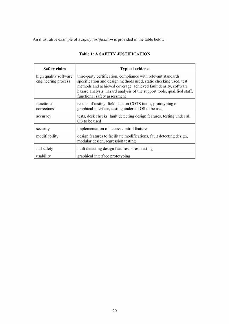
It is advisable for a developer to produce a summary document (perhaps called a safety justification or a dependability case). It should contain:
�� A summary of the safety claims for the systems. Typically these are:
�� a high quality software engineering process;
�� functional correctness;
�� accuracy (the results are sufficiently accurate when calculated using finite-precision arithmetic, and numerical instability should be detected)
�� security (appropriate steps are taken to prevent malicious and accidental changes to methods and data)
�� modifiability (the chance of maintenance-induced errors is minimised)
�� fail safety (there is a low probability of unrevealed failures)
�� usability (the system makes it hard for users to make errors)
�� A summary of the IEC 61508-compliant activities carried out, explaining how these provide evidence to support the safety claims. This summary can also be used to justify the inclusion or omission of techniques from the tables in Part 3 Annex A.
20
An illustrative example of a safety justification is provided in the table below.
Table 1: A SAFETY JUSTIFICATION
Safety claim Typical evidence
high quality software engineering process
third-party certification, compliance with relevant standards, specification and design methods used, static checking used, test methods and achieved coverage, achieved fault density, software hazard analysis, hazard analysis of the support tools, qualified staff, functional safety assessment
functional correctness
results of testing, field data on COTS items, prototyping of graphical interface, testing under all OS to be used
accuracy tests, desk checks, fault detecting design features, testing under all OS to be used
security implementation of access control features
modifiability design features to facilitate modifications, fault detecting design, modular design, regression testing
fail safety fault detecting design features, stress testing
usability graphical interface prototyping

21
7. COMPLIANCE MATRIX
This document summarises the main items of IEC 61508 to which a developer of safety related software advisory systems must pay practical attention. To assist the developer who needs further background information, the following table cross-refers the advice given in this document with the specific IEC 61508 clauses
IEC 61508 compliance matrix
part / clause
topic developer's response
I / 7.2, 7.3 risk reduction, scope 3.3.1
I / 6, 8 functional safety: planning, assessment 4, 6, Appendices 1+2
I / 7 safety lifecycle 3.3
I / 7.4 hazard analysis, safety functions 1.2, 2.2
II hardware integrity 3.2, 3.3.2
I / 7.5 SIL assessment 2.3, Appendix 3
III software safety lifecycle 3.3.3
III Annex A selection of software techniques 3.3.3
III / 7.4 software reuse 3.3.3
III / 7.6, 7,8 software maintenance 3.3.3
I / Annex A documentation 6
III / 6 software quality management 5, Appendices 1+2

22

23
Appendix 1: IEC 61508 compliance illustrated using a certified QMS
A1- 1 INTRODUCTION The following is a detailed worked example, by reference to the detailed procedures of a 3rd party certified ISO 9001 quality management system (QMS), to show how IEC 61508 compliance may be achieved.
The following table outlines the extent to which a basic certified QMS will meet the requirements of IEC 61508, summarises the additional techniques and methods that may be needed, and provides references to more detailed guidance.
IEC 61508 requirement Coverage by certified QMS Reference
Functional safety planning Yes. Section A1-2
Software configuration management
Yes. Section A1-6
Software safety lifecycle Development lifecycle covered; needs mapping to safety lifecycle.
Section A1-2
Software safety requirements specification
Yes, but may not cover specific techniques in IEC 61508-3 Table A.1.
Section A1-3
Software safety validation planning
Yes. Section A1-5
Software design and development (general)
Yes, but may not cover how to obtain increased confidence from use.
Section A1-4
Software design and development (software architecture)
Yes, but may not cover specific techniques in IEC 61508-3 Tables A.2 and B.7.
Section A1-4.1
Software design and development (support tools and programming languages)
Yes, but may not cover specific techniques in IEC 61508-3 Table A.3.
Section A1-4.2
Software design and development (detailed design and development)
Yes, but may not cover specific techniques in IEC 61508-3 Tables A.4, B.1, B.7 and B.9.
Section A1-4.3
Software design and development (code implementation)
Yes. Section A1-4.3
Software design and development (software module and integration testing)
Yes, but may not cover specific techniques in IEC 61508-3 Tables A.5, B.2, B.3 and B.6. Also may not cover assurance of software packages, and may not identify all the required test plans.
Section A1-5, Section A1-5.1

24
IEC 61508 requirement Coverage by certified QMS Reference
Programmable electronics integration
Not explicitly. For advisory systems, this involves the normal procedures for installing software on stand-alone or networked PCs.
—
Software operation and modification procedures
Yes. Section A1-6
Software modification Yes. Section A1-6
Software safety validation Yes, but may not cover qualification of test tools.
Section A1-5, Section A1-5.2
Software verification Yes, but may not cover specific techniques in IEC 61508-3 Tables A.9, B.2 and B.8. Also, 10 phases of verification may be condensed.
Section A1-5.3
A1- 2 PLANNING The certified QMS will include quality planning, either by production of a separate document or as part of another plan, such as the overall project plan. For IEC 61508 compliance, quality planning procedures should include functional safety planning, addressing software procurement, development, integration, verification, validation and modification. Functional safety planning should identify the specific methods and techniques used to produce software of the required SIL.
Where the developer’s quality plan does not specify use of technique or method that is HR for the SIL of the target application in IEC 61508, a justification for its exclusion should be made in the plan, which could be based on:
�� the use of an alternative, equally strong, method (e.g. formal methods instead of structured methods)
�� special features of the application that make the recommendation inappropriate (e.g. the use of recursion may be permitted for an advisory system where a lack of resources will simply cause the system to fail to produce a result)
�� unacceptable risk to project costs or timescales would be introduced by use of the technique or measure because it is relatively untried in practice (e.g. the use of recovery blocks)
The quality plan will be organised according to a lifecycle model for the development. This may range from a conventional waterfall model to incremental builds and rapid application development (RAD). For IEC 61508 compliance, this should be mapped to the software safety lifecycle. Where there is iteration of one or more steps (e.g. requirements, design and development in a RAD lifecycle), the documents required by IEC 61508 should be regarded as “living documents” and also be developed iteratively, with the final versions being completed when the software is released to the following stages.
A1- 3 SOFTWARE SAFETY REQUIREMENTS SPECIFICATION The QMS will include development and review of the purchaser’s requirements specification, which may be produced by the purchaser or by the developer in close co-operation with the purchaser. For IEC 61508 compliance, the requirements specification should include the

25
software safety requirements specification (see IEC 61508-3 7.2.2.11). Contract review should include confirmation that the generic assumptions of the purchaser’s hazard analysis apply, and that the SILs are correctly allocated.
A certified QMS may contain no requirements for computer-aided specification tools, semi-formal or formal methods. In this case, for IEC 61508 compliance, the developer should consider augmenting it as shown in the table below.
Technique/measure SIL 1 SIL 2 Guidance
1. Computer-aided specification tools
R R The process for developing and reviewing the requirements specification should include tool support, e.g. a requirements database.
2a Semi-formal methods R R The specification should use semi-formal diagrammatic notations.
2b Formal methods — R Alternatively, for SIL 2, formal methods can be used.
A1- 4 DESIGN AND IMPLEMENTATION The QMS will include a design procedure, enforcing the use of an appropriate, systematic design methodology. To conform to IEC 61508, this should be a structured method, or a semi-formal or formal method. This should be tool supported unless the development is very simple.
IEC 61508-3 contains tables on architectural and detailed design. For most advisory systems, consisting of up to around 50 000 lines of code, a single design description may be sufficient. If two or more design descriptions are used, the relationship between them should be justified.
ISO 9000-3 does not address the assurance of design tools and software libraries and a certified QMS may therefore not contain procedures on how to obtain increased confidence from use. Specific plans for this, following the guidance in IEC 61508-7, should be included in the Quality Plan.
A1- 4.1 SOFTWARE ARCHITECTURE DESIGN The architectural design procedure in a certified QMS will normally conform to IEC 61508 by requiring that the design is modular and uses techniques to improve maintainability, such as abstraction, information hiding and encapsulation. It will require documentation to describe the way that the software is partitioned into subsystems, components and/or modules. For each of these, the following information should be available:
�� whether it is new, existing or proprietary
�� whether it has been previously verified, and if yes, what verification was carried out
�� the required SIL
The design should describe and evaluate for safety the interactions between the hardware and software. For advisory systems, this information may include:
�� device drivers used (e.g. for disks)
�� operating system features (e.g. caching and memory management)

26
�� fault detection features (e.g. comparators/voters)
IEC 61508 requires that design notations are “unambiguously defined”. In practice only formal methods and certain semi-formal methods (e.g. some finite state machines/state transition diagrams, time Petri nets, decision/truth tables) meet this requirement. For the others, an unambiguous definition can be taken to be one of:
�� a definition in an international or national standard
�� a description in a published textbook
�� a description in a supplier’s manual
In-house methods should be avoided for safety related advisory systems unless they meet the above requirements, and have been used successfully on previous projects at the same integrity level or higher.
The following table contains guidance on specific techniques and measures for architectural design.
Technique/measure SIL 1 SIL 2 Guidance
1. Fault detection and diagnostics
— R Fault detection should be implemented where safety analysis shows that it is necessary to achieve the safety integrity of the system. Applicable methods include the use of diverse algorithms, interval arithmetic1, detection of stale values and generation of alternative outputs (e.g. displayed and printed). User input should also be checked. Unexpected overflow should result in program termination. Note that the PC hardware and operating system provide some limited validation of the software through traps for division by zero, illegal memory access etc.
2. Error detecting and correcting codes
R R As (1). Features to check and maintain the integrity of data include checksums, parity and CRC checks , and time stamping of data. The design should discard faulty data rather than attempting correction.
3a-h. Fault tolerance etc.
R/— R As this class of advisory system is used only in design, fault tolerance is not necessary.
4. Graceful degradation
R R As this class of advisory system is used only in design, graceful degradation is not necessary but the design should aim for clean termination if errors are detected.
1 This techniques carries one or more additional values, slightly perturbed from the true value, through the calculation, and fails safe if the additional value(s) have diverged by more than a pre-set threshold from the true value.

27
Technique/measure SIL 1 SIL 2 Guidance
5. Artificial intelligence
— NR AI techniques are likely to be of interest when the class of advisory system is inherently rule-based.
6. Dynamic reconfiguration
— NR For example, the layout of forms and menus in the user interface should be defined statically, rather than determined dynamically.
7a. Structured methods
HR HR
7b. Semi-formal methods
R R
7c. formal methods — R
8. Computer-aided specification tools
R R
A1- 4.2 SUPPORT TOOLS AND PROGRAMMING LANGUAGE IEC 61508 requires that a suitable programming language is selected. It also requires that the programming language is completely and unambiguously defined, or if not the justification for any alternative language detailing its fitness for purpose is documented. Currently, very few languages are unambiguously defined and so it will normally be necessary to assess fitness for purpose.
Suitability and fitness for purpose can be determined by assessing the fit to:
�� the problem
�� the product
�� the people
�� the process
The following table contains guidance on specific techniques and measures for development tools and programming language.
Technique/measure SIL 1 SIL 2 Guidance
1. Suitable programming language
HR HR A certified QMS will enforce the use of appropriate implementation methods and tools. Visual languages such as C++ and Visual Basic may be the best fit for developing Windows graphical interfaces, in which case a suitable coding standard should be applied. Some of the deprecated features in IEC 61508, such as recursion, may not apply to this class of advisory system, since failure to provide a result is fail-safe. Languages such as Prolog, which are a good

28
Technique/measure SIL 1 SIL 2 Guidance fit to other aspects of the problem, should be used in accordance with an applicable coding standard.
2. Strongly typed programming language
HR HR For this class of PC application, languages which are not strongly typed such as C++, Visual Basic and Prolog may have advantages. In this case, static analysis should be carried out to detect type mismatches. Those parts of the implementation for which a static justification of type correctness cannot be given should check these properties dynamically and should not give a result unless they are satisfied.
3. Language subset — — If C/C++ is used, a language subset is recommended.
4a. Certificated tools R HR There are very few if any certificated tools for the languages likely to be employed in advisory software, and “proven in use” arguments will be needed (see IEC 61508-7). A list of known errors and limitations of the tools used should be maintained throughout the project. This should include the tool supplier’s list of problems reported by the user base, where available. These areas of the tools should be avoided, or an argument provided that the safety of the development is not affected by their use.
4b. Tools: increased confidence from use
HR HR See IEC 61508-7 for guidance.
5a. Certificated translator
R HR As 4a.
5b. Translator: increased confidence from use
HR HR See IEC 61508-7 for guidance.
6. Libraries of trusted/verified software modules and components
R HR These could include ActiveX components, provided that increased confidence from use can be justified. See IEC 61508-7.
A1- 4.3 DETAILED DESIGN AND CODE IMPLEMENTATION The following table contains guidance on specific techniques and measures for detailed design. See also the comments on design notations in Section 4.1.
Technique/measure SIL 1 SIL 2 Guidance
1a. Structured methods HR HR

29
Technique/measure SIL 1 SIL 2 Guidance
1b. Semi-formal methods
R HR
2. Computer-aided design tools
— R
3. Defensive programming
R R Defensive programming should address failures identified by the safety analysis that can be identified by software at run time. All results which could be affected by such a failure should be flagged as suspect. No data affected by a failure should be placed in permanent storage. Those parts of the implementation for which a static justification of type correctness cannot be given should check these properties dynamically and should not give a result unless they are satisfied.
4. Modular approach HR HR
5. Design and coding standards
R HR A certified QMS will enforce rules covering consistent naming, coding and commenting. More detail is given in IEC 61508-3 Table B.1 and in Part 7.
6. Structured programming
HR HR
7. Use of trusted/verified software modules and components (if available)
R HR See IEC 61508-7 for guidance.
A1- 5 TESTING AND VALIDATION A certified QMS will contain a test procedure, which will include consideration of functional, boundary, performance and usability tests, with recording of expected and actual results. The test procedure will also address the evaluation of test relevance and adequacy; this process will provide the justification for the choice of techniques from IEC 61508.
A certified QMS will also address planning for testing and validation. To conform to IEC 61508, the following plans should be produced:
�� safety validation plan. This should be produced concurrently with software design and development.
�� software module test plan. This need not be a distinct document.
�� software integration test plan. This need not be a distinct document.
�� integration tests (hardware and software). This need not be a distinct document. These tests should be specified during the design and development phase.
30
ISO 9000-3 does not address the assurance of software packages and a certified QMS may therefore not contain procedures on how to obtain increased confidence from use. Specific plans for this, following the guidance in IEC 61508-7, should be included in the Quality Plan.
A certified QMS will address test environment, tools and test software at the planning phase, but this may not go as far as qualification as defined in IEC 61508-3, 7.7.2.7. Qualification should be based on a clear specification of the function of the tools, indicating what classes of faults will be detected and what will not, coupled with evidence that the tool is adequately reliable, normally using a proven in use argument.
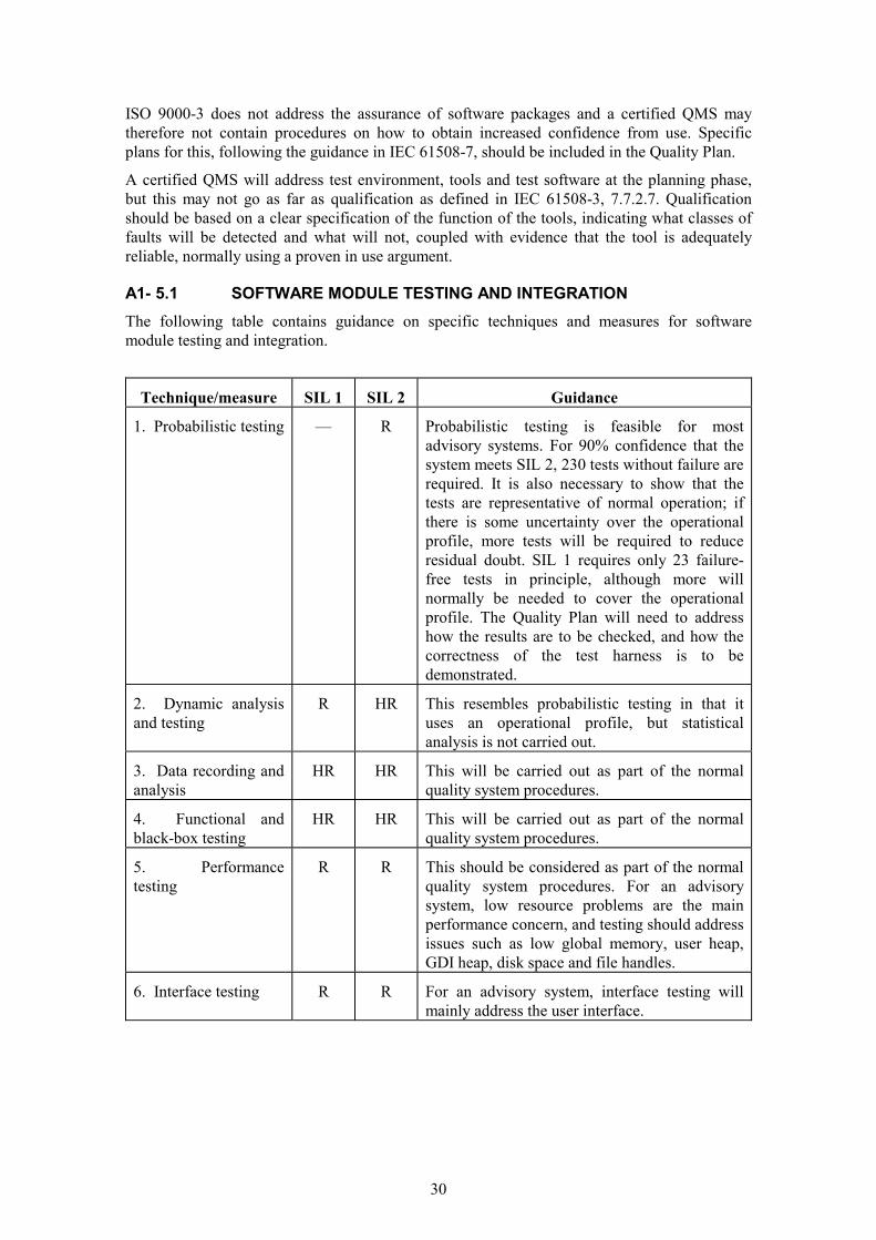
A1- 5.1 SOFTWARE MODULE TESTING AND INTEGRATION The following table contains guidance on specific techniques and measures for software module testing and integration.
Technique/measure SIL 1 SIL 2 Guidance
1. Probabilistic testing — R Probabilistic testing is feasible for most advisory systems. For 90% confidence that the system meets SIL 2, 230 tests without failure are required. It is also necessary to show that the tests are representative of normal operation; if there is some uncertainty over the operational profile, more tests will be required to reduce residual doubt. SIL 1 requires only 23 failure-free tests in principle, although more will normally be needed to cover the operational profile. The Quality Plan will need to address how the results are to be checked, and how the correctness of the test harness is to be demonstrated.
2. Dynamic analysis and testing
R HR This resembles probabilistic testing in that it uses an operational profile, but statistical analysis is not carried out.
3. Data recording and analysis
HR HR This will be carried out as part of the normal quality system procedures.
4. Functional and black-box testing
HR HR This will be carried out as part of the normal quality system procedures.
5. Performance testing
R R This should be considered as part of the normal quality system procedures. For an advisory system, low resource problems are the main performance concern, and testing should address issues such as low global memory, user heap, GDI heap, disk space and file handles.
6. Interface testing R R For an advisory system, interface testing will mainly address the user interface.

31
A1- 5.2 SOFTWARE SAFETY VALIDATION The following table contains guidance on specific techniques and measures for software safety validation.
Technique/measure SIL 1 SIL 2 Guidance
1. Probabilistic testing — R See Section A1 - 5.1 (1).
2. Simulation/ modelling
R R Generally, these techniques are not applicable to advisory systems.
3. Functional and black box testing
HR HR See Section A1 - 5.1 (4).
A1- 5.3 SOFTWARE VERIFICATION IEC 61508-3 calls for 10 phases of software verification. For advisory systems, where several development steps may be condensed into a single step (e.g. a single design step instead of architectural, system and module design—see also Section A1-4) the verification steps will also be condensed.
The following table contains guidance on specific techniques and measures for software verification.
Technique/measure SIL 1 SIL 2 Guidance
1. Formal proof — R Not addressed by ISO 9000-3 and so may not be included in a certified QMS. Proof of selected safety properties may be cost-effective, though usually only where formal methods have been used at the specification and design stage.
3. Probabilistic testing — R See Section A1 - 5.1 (1).
4. Static analysis R HR See discussion of strongly typed programming languages in Section A1 - 4.2 (2). This includes design walk-throughs; a certified QMS will document the extent to which components of the final system are to be reviewed, and at what stages.
5. Dynamic analysis and testing
R HR See Section A1 - 5.1 (2).
6. Software complexity metrics
R R A certified QMS will enforce the reporting of metrics, with measures of field failures as a minimum. Other metrics should be used where they are already part of the QMS.
A1- 6 CORRECTIVE ACTION AND CONFIGURATION MANAGEMENT The modification requirements of IEC 61508 will all be required by a certified QMS. The following table contains guidance on specific techniques and measures for modification and configuration management.

32
Technique/measure SIL 1 SIL 2 Guidance
1. Impact analysis HR HR This is a standard part of corrective action and change control, except that it should include hazard analysis of the proposed change.
2. Reverify changed modules
HR HR This is a standard part of corrective action and change control.
3. Reverify affected modules
R HR This is a standard part of corrective action and change control.
4. Revalidate complete system
— R This is a standard part of corrective action and change control.
5. Software configuration management
HR HR This will be carried out as part of the normal QMS procedures. The configuration management system will comprise administrative procedures with tool support.
6. Data recording and analysis
HR HR A certified QMS should contain a procedure for in-service failure data recording and analysis. Records should include: the specific application; the nature of the failure; the configuration of the software and system; and the number of occurrences of the fault. (See also Section A1 - 5.1 (4).)

33
Appendix 2: IEC 61508 compliance using a non-certified or non-software QMS
The following is a detailed worked example showing how IEC 61508 compliance may be achieved using a quality management system that is not 3rd party certified, or a system that does not specifically address software. It follows the structure of the guidance for a certified quality management system but is a self-contained section, and therefore repeats the information that is common to both certified and non-certified systems.
A2 - 1.1 DOCUMENTATION IEC 61508 requires the documentation of a number of plans and reports. However, these do not have to be separate documents, and one possible way of organising them into physical documents is shown in the table below.
Note that a physical document does not necessarily have to be a paper document; some documents, especially code listing and test results, may be most conveniently held only in electronic form. Where the developer already has procedures covering some of the methods and techniques required by IEC 61508, these can be referenced as appropriate.
Developer’s physical document
IEC 61508 “document” Guidance
Project plan Software safety plan, software validation plan, software verification plan (including module and integration tests), software modification plan
Section A2 - 2
Software safety requirements
Software safety requirements Section A2 - 3
Software design Design description (may be single description or separated into architectural design, software system design and module design), design changes following modifications
Section A2 - 4, Section A2 - 6
Source code Source code Section A2 - 4.2, Section A2 - 4.3
Review records Code review, design review, software modification impact analysis
Section A2 - 5.3, Section A2 - 6
Test specification and results
As appropriate, integration tests, module tests, software safety validation, regression and other tests following modifications. Test specifications should include expected results.
Section A2 - 5, Section A2 - 6
User’s manual User’s manual
Operation and maintenance manual
Operation and maintenance manual
Change requests Software modification requests Section A2 - 6
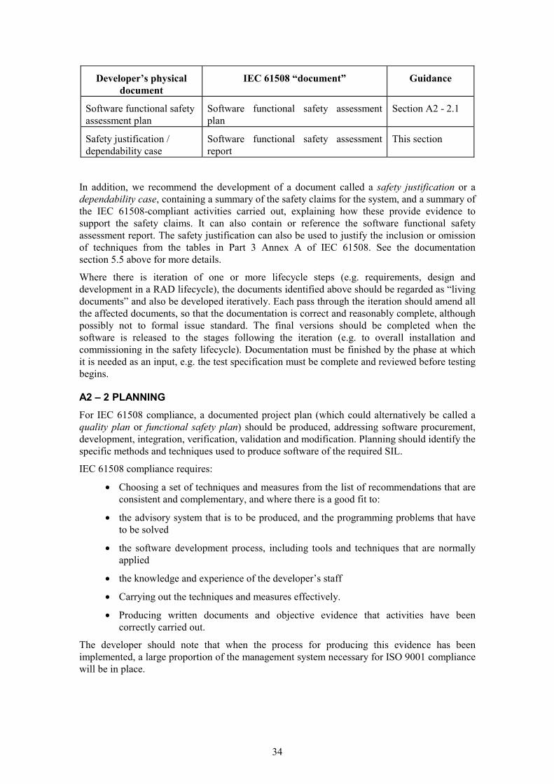
34
Developer’s physical document
IEC 61508 “document” Guidance
Software functional safety assessment plan
Software functional safety assessment plan
Section A2 - 2.1
Safety justification / dependability case
Software functional safety assessment report
This section
In addition, we recommend the development of a document called a safety justification or a dependability case, containing a summary of the safety claims for the system, and a summary of the IEC 61508-compliant activities carried out, explaining how these provide evidence to support the safety claims. It can also contain or reference the software functional safety assessment report. The safety justification can also be used to justify the inclusion or omission of techniques from the tables in Part 3 Annex A of IEC 61508. See the documentation section 5.5 above for more details.
Where there is iteration of one or more lifecycle steps (e.g. requirements, design and development in a RAD lifecycle), the documents identified above should be regarded as “living documents” and also be developed iteratively. Each pass through the iteration should amend all the affected documents, so that the documentation is correct and reasonably complete, although possibly not to formal issue standard. The final versions should be completed when the software is released to the stages following the iteration (e.g. to overall installation and commissioning in the safety lifecycle). Documentation must be finished by the phase at which it is needed as an input, e.g. the test specification must be complete and reviewed before testing begins.
A2 – 2 PLANNING For IEC 61508 compliance, a documented project plan (which could alternatively be called a quality plan or functional safety plan) should be produced, addressing software procurement, development, integration, verification, validation and modification. Planning should identify the specific methods and techniques used to produce software of the required SIL.
IEC 61508 compliance requires:
�� Choosing a set of techniques and measures from the list of recommendations that are consistent and complementary, and where there is a good fit to:
�� the advisory system that is to be produced, and the programming problems that have to be solved
�� the software development process, including tools and techniques that are normally applied
�� the knowledge and experience of the developer’s staff
�� Carrying out the techniques and measures effectively.
�� Producing written documents and objective evidence that activities have been correctly carried out.
The developer should note that when the process for producing this evidence has been implemented, a large proportion of the management system necessary for ISO 9001 compliance will be in place.

35
Where the developer’s project plan does not specify the use of a technique or method that is HR for the SIL of the target application in IEC 61508, a justification for its exclusion should be made in the plan, which could be based on:
�� the use of an alternative, equally strong, method (e.g. formal methods instead of structured methods)
�� special features of the application that make the recommendation inappropriate (e.g. the use of recursion may be permitted for an advisory system where a lack of resources will simply cause the system to fail to produce a result)
�� an unacceptable risk to project costs or timescales that would be introduced by use of the technique or measure because it is relatively untried in practice (e.g. the use of recovery blocks)
For IEC 61508 compliance, the project plan should be organised according to a lifecycle model for the development. This may range from a conventional waterfall model to incremental builds and rapid application development (RAD). This should be mapped to the IEC 61508 software safety lifecycle. The impact of RAD-style lifecycles on documentation has already been discussed in Section A2 - 1.1.
Some advisory systems may be produced by small teams, even a single person. The project plan should explain how independent review and checking is to be carried out in these circumstances. One possibility is to negotiate some effort from someone with applicable experience from a different part of the organisation. For very small enterprises, it may be possible to link up with another similar firm to provide independent reviewers on each other’s projects.
A2 - 2.1 SOFTWARE FUNCTIONAL SAFETY ASSESSMENT PLAN This plan should be drawn up by the person or team carrying out the functional safety assessment. The independence requirements for the functional safety assessor (see the section on planning and assessing functional safety earlier in this guide) can be met as described above for independent review and checking.
A2 – 3 SOFTWARE SAFETY REQUIREMENTS SPECIFICATION The developer should carry out a documented review of HSE’s requirements specification, which may be produced by HSE or by the developer in close co-operation with HSE. For IEC 61508 compliance, the requirements specification should include the software safety requirements specification (see IEC 61508-3 7.2.2.11). The review should include confirmation that the generic assumptions (see Appendix 3) of the HSE’s hazard analysis apply, and that the SILs are correctly allocated.
The developer should consider carrying out development of the safety related software using computer-aided specification tools as shown in the table below. In this, and the following tables, the numbered items with a, b, … suffixes are techniques or measures which are recommended as alternatives, i.e. only one of 2a and 2b is required.
Technique/measure SIL 1 SIL 2 Guidance
1. Computer-aided specification tools
R R The process for developing and reviewing the requirements specification should include tool support, e.g. a requirements database.

36
Technique/measure SIL 1 SIL 2 Guidance
2a Semi-formal methods R R The specification should use semi-formal diagrammatic notations.
2b Formal methods — R Alternatively, for SIL 2, formal methods can be used.
4 DESIGN AND IMPLEMENTATION To conform to IEC 61508, the developer should apply a design procedure enforcing the use of an appropriate, systematic design methodology. This should be a structured method, or a semi-formal or formal method. This should be tool supported unless the development is very simple.
IEC 61508-3 contains tables on architectural and detailed design. For most advisory systems, consisting of up to around 50 000 lines of code, a single design description may be sufficient. If two or more design descriptions are used, the relationship between them should be justified.
Specific plans for how to obtain increased confidence from use for tools and translators (see Section A2 - 4.2), following the guidance in IEC 61508-7, should be included in the project plan.
A2 - 4.1 SOFTWARE ARCHITECTURE DESIGN To conform to IEC 61508, the architectural design should be modular and use techniques to improve maintainability, such as abstraction, information hiding and encapsulation. The developer should produce documentation to describe the way that the software is partitioned into subsystems, components and/or modules. For each of these, the following information should be available:
�� whether it is new, existing or proprietary
�� whether it has been previously verified, and if yes, what verification was carried out
�� the required SIL
The design should describe and evaluate for safety the interactions between the hardware and software. For advisory systems, this information may include:
�� device drivers used (e.g. for disks)
�� operating system features (e.g. caching and memory management)
�� fault detection features (e.g. comparators/voters)
IEC 61508 requires that design notations are “unambiguously defined”. In practice only formal methods and certain semi-formal methods (e.g. some finite state machines/state transition diagrams, time Petri nets, and decision/truth tables) meet this requirement. For the others, an unambiguous definition can be taken to be one of:
�� a definition in an international or national standard
�� a description in a published textbook
�� a description in a supplier’s manual
In-house methods should be avoided for safety related advisory systems unless they meet the above requirements, and have been used successfully on previous projects at the same integrity level or higher.
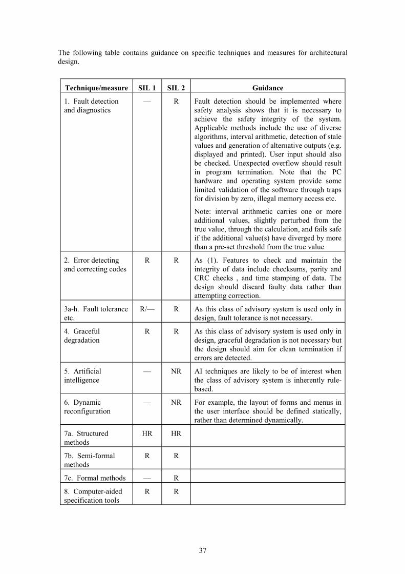
37
The following table contains guidance on specific techniques and measures for architectural design.
Technique/measure SIL 1 SIL 2 Guidance
1. Fault detection and diagnostics
— R Fault detection should be implemented where safety analysis shows that it is necessary to achieve the safety integrity of the system. Applicable methods include the use of diverse algorithms, interval arithmetic, detection of stale values and generation of alternative outputs (e.g. displayed and printed). User input should also be checked. Unexpected overflow should result in program termination. Note that the PC hardware and operating system provide some limited validation of the software through traps for division by zero, illegal memory access etc.
Note: interval arithmetic carries one or more additional values, slightly perturbed from the true value, through the calculation, and fails safe if the additional value(s) have diverged by more than a pre-set threshold from the true value
2. Error detecting and correcting codes
R R As (1). Features to check and maintain the integrity of data include checksums, parity and CRC checks , and time stamping of data. The design should discard faulty data rather than attempting correction.
3a-h. Fault tolerance etc.
R/— R As this class of advisory system is used only in design, fault tolerance is not necessary.
4. Graceful degradation
R R As this class of advisory system is used only in design, graceful degradation is not necessary but the design should aim for clean termination if errors are detected.
5. Artificial intelligence
— NR AI techniques are likely to be of interest when the class of advisory system is inherently rule-based.
6. Dynamic reconfiguration
— NR For example, the layout of forms and menus in the user interface should be defined statically, rather than determined dynamically.
7a. Structured methods
HR HR
7b. Semi-formal methods
R R
7c. Formal methods — R
8. Computer-aided specification tools
R R

38
A2 - 4.2 SUPPORT TOOLS AND PROGRAMMING LANGUAGE IEC 61508 requires that a suitable programming language is selected. It also requires that the programming language is completely and unambiguously defined, or if not the justification for any alternative language detailing its fitness for purpose is documented. Currently, very few languages are unambiguously defined and so it will normally be necessary to assess fitness for purpose.
Suitability and fitness for purpose can be determined by assessing the fit to:
�� the problem
�� the product
�� the people
�� the process
The following table contains guidance on specific techniques and measures for development tools and programming language.
Technique/measure
SIL 1 SIL 2 Guidance
1. Suitable programming language
HR HR The developer should justify the choice of programming language. Visual languages such as C++ and Visual Basic may be the best fit for developing Windows graphical interfaces, in which case a suitable coding standard should be applied. Some of the deprecated features in IEC 61508, such as recursion, may not apply to this class of advisory system, since failure to provide a result is fail-safe. Languages such as Prolog, which are a good fit to other aspects of the problem, should be used in accordance with an applicable coding standard.
2. Strongly typed programming language
HR HR For this class of PC application, languages which are not strongly typed such as C++, Visual Basic and Prolog may have advantages. In this case, static analysis should be carried out to detect type mismatches. Those parts of the implementation for which a static justification of type correctness cannot be given should check these properties dynamically and should not give a result unless they are satisfied.
3. Language subset — — If C/C++ is used, a language subset is recommended.
4a. Certificated tools
R HR There are very few if any certificated tools for the languages likely to be employed in advisory software, and “proven in use” arguments will be needed (see IEC 61508-7), i.e. 4b will be used.

39
Technique/measure
SIL 1 SIL 2 Guidance
4b. Tools: increased confidence from use
HR HR A list of known errors and limitations of the tools used should be maintained throughout the project. This should include the tool supplier’s list of problems reported by the user base, where available. These areas of the tools should be avoided, or an argument provided that the safety of the development is not affected by their use. See IEC 61508-7 for further guidance.
5a. Certificated translator
R HR I.e. a compiler. As 4a.
5b. Translator: increased confidence from use
HR HR See 4b and IEC 61508-7 for guidance.
6. Libraries of trusted/verified software modules and components
R HR These could include ActiveX components, provided that increased confidence from use can be justified. See IEC 61508-7.
A2 - 4.3 DETAILED DESIGN AND CODE IMPLEMENTATION The following table contains guidance on specific techniques and measures for detailed design. See also the comments on design notations in Section A2 - 4.1.
Technique/measure SIL 1 SIL 2 Guidance
1a. Structured methods
HR HR
1b. Semi-formal methods
R HR
2. Computer-aided design tools
— R
3. Defensive programming
R R Defensive programming should address failures identified by the safety analysis that can be identified by software at run time. All results which could be affected by such a failure should be flagged as suspect. No data affected by a failure should be placed in permanent storage. Those parts of the implementation for which a static justification of type correctness cannot be given should check these properties dynamically and should not give a result unless they are satisfied.
4. Modular approach HR HR
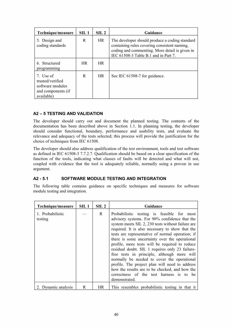
40
Technique/measure SIL 1 SIL 2 Guidance
5. Design and coding standards
R HR The developer should produce a coding standard containing rules covering consistent naming, coding and commenting. More detail is given in IEC 61508-3 Table B.1 and in Part 7.
6. Structured programming
HR HR
7. Use of trusted/verified software modules and components (if available)
R HR See IEC 61508-7 for guidance.
A2 – 5 TESTING AND VALIDATION The developer should carry out and document the planned testing. The contents of the documentation has been described above in Section 1.1. In planning testing, the developer should consider functional, boundary, performance and usability tests, and evaluate the relevance and adequacy of the tests selected; this process will provide the justification for the choice of techniques from IEC 61508.
The developer should also address qualification of the test environment, tools and test software as defined in IEC 61508-3 7.7.2.7. Qualification should be based on a clear specification of the function of the tools, indicating what classes of faults will be detected and what will not, coupled with evidence that the tool is adequately reliable, normally using a proven in use argument.
A2 - 5.1 SOFTWARE MODULE TESTING AND INTEGRATION The following table contains guidance on specific techniques and measures for software module testing and integration.
Technique/measure SIL 1 SIL 2 Guidance
1. Probabilistic testing
— R Probabilistic testing is feasible for most advisory systems. For 90% confidence that the system meets SIL 2, 230 tests without failure are required. It is also necessary to show that the tests are representative of normal operation; if there is some uncertainty over the operational profile, more tests will be required to reduce residual doubt. SIL 1 requires only 23 failure-free tests in principle, although more will normally be needed to cover the operational profile. The project plan will need to address how the results are to be checked, and how the correctness of the test harness is to be demonstrated.
2. Dynamic analysis R HR This resembles probabilistic testing in that it

41
Technique/measure SIL 1 SIL 2 Guidance and testing uses an operational profile, but statistical
analysis is not carried out.
3. Data recording and analysis
HR HR Test results should be documented as described above and in Section A2 - 1.1. Results should include the criticality of the failure, e.g. “safety related”, “significant” or “minor”. The number of outstanding defects should be tracked.
4. Functional and black-box testing
HR HR This is testing carried out at the functional level without consideration of the internal structure of the software.
5. Performance testing
R R For an advisory system, low resource problems are the main performance concern, and testing should address issues such as low global memory, user heap, GDI heap, disk space and file handles.
6. Interface testing R R For an advisory system, interface testing will mainly address the user interface.
A2 - 5.2 Software safety validation
The following table contains guidance on specific techniques and measures for software safety validation.
Technique/measure SIL 1 SIL 2 Guidance
1. Probabilistic testing — R See Section A2 - 5.1 (1).
2. Simulation/ modelling
R R Generally, these techniques are not applicable to advisory systems.
3. Functional and black box testing
HR HR See Section A2 - 5.1 (4).
A2 - 5.3 SOFTWARE VERIFICATION IEC 61508-3 calls for 10 phases of software verification. For advisory systems, where several development steps may be condensed into a single step (e.g. a single design step instead of architectural, system and module design—see also Section 4) the verification steps will also be condensed.

42
Technique/measure SIL 1 SIL 2 Guidance
1. Formal proof — R Proof of selected safety properties may be cost-effective, though usually only where formal methods have been used at the specification and design stage.
3. Probabilistic testing
— R See Section A2 - 5.1 (1).
4. Static analysis R HR See discussion of strongly typed programming languages in Section A2 - 4.2 (2). This includes design walk-throughs; the developer should document in the project plan the extent to which components of the final system are to be reviewed, and at what stages.
5. Dynamic analysis and testing
R HR See Section A2 - 5.1 (2).
6. Software complexity metrics
R R The developer should document a policy for reporting metrics in the project plan. Possible metrics include fault density (the number of faults per 1000 lines of code) and complexity (e.g. number of function points). Measures of field failures are a reasonable minimum.
A2 - 6 CORRECTIVE ACTION AND CONFIGURATION MANAGEMENT The following table contains guidance on specific techniques and measures for modification and configuration management.
Technique/measure SIL 1 SIL 2 Guidance
1. Impact analysis HR HR The developer should document in the project plan how the impact of changes to the software is to be analysed. The analysis should include hazard analysis of the proposed change.
2. Reverify changed modules
HR HR The developer should document in the project plan how changed software modules are to be reverified. This will normally be by repeating all or part of the previous verification activities (e.g. review and testing), plus applying regression testing.
3. Reverify affected modules
R HR The developer should document in the project plan how software modules affected by changes are to be reverified. This will normally be by repeating all or part of the previous verification activities (e.g. review and testing), plus applying regression testing.
A2 - 5.3 SOFTWARE VERIFICATION IEC 61508-3 calls for 10 phases of software verification. For advisory systems, where several
The following table contains guidance on specific techniques and measures for software verification.

43
Technique/measure SIL 1 SIL 2 Guidance
4. Revalidate complete system
— R Normally for an advisory system, the complete system will be subjected to some retesting following a change.
5. Software configuration management
HR HR The developer should apply a documented procedure for configuration management. This should make it possible to identify software items, and determine for each version of an item the specification, design and other documents, interfaces to other software items, and development tools (e.g. compilers). See IEC 61508-3 6.2.3 c for a list of configuration items.
Configuration management should also control editing of individual files, and enable the system to be “rolled back” to a previous version. The configuration management system will comprise administrative procedures with tool support.
6. Data recording and analysis
HR HR The developer should, in co-operation with HSE, apply a procedure for in-service failure data recording and analysis. Records should include: the specific application; the nature of the failure; the configuration of the software and system; and the number of occurrences of the fault. (See also Section A2 - 5.1 (3).)

44

45
Appendix 3: Generic SIL assessment of advisory software
This section sets out an argument that establishes the SIL that advisory software must achieve. It has been generalised from the real assessment of a program that was developed to assist in the design of explosion relief in safety-related machinery. Although the key inputs to this argument are expressed in terms of numbers, these numbers are usually not available as reliable empirical data. However, this is not the insurmountable obstacle that it appears to be. In practice, a judgement on safety depends strongly on qualitative factors e.g. personal competence, acceptability of consequences, societal sensitivity. A purely numerical assessment would disguise these important subjective aspects and would likely introduce a misleading impression of rigour.
In this argument these key inputs should be regarded as Bayesian probabilities i.e. an expression of the degree of belief in a proposition, rather than as empirical data on the frequency of events. This Bayesian assertion must of course be defendable. One possible defence would be the opinion of a credible and experienced expert in the topic. Where available, reliable empirical data can also be used.
IEC 61506 characterises the safety integrity of a safety-related program as a “probability of failure on demand” or “PFD”.
Table A3-1: SAFETY INTEGRITY LEVEL PFD
Safety
integrity level
probability of failure to perform its design function on demand
4 � 10-5 to � 10–4 3 � 10–4 to � 10–3 2 � 10–3 to � 10–2 1 � 10–2 to � 10–1
The direction of this argument is to take account of the key factors that influence the occurrence of bad outcomes, to show how important the software is in increasing or decreasing these bad outcomes, and to make a judgement on an acceptable SIL for the software.
Examples of a bad outcome include:
�� in machinery design: a machinery malfunction due to a bad design decision.
�� in land-use planning: an unsafe course of action resulting from wrong advice.
The key considerations are:
�� Non-software sources of bad outcomes. The advisory software of interest here is not usually the sole source of bad outcomes. For example: machinery may be correctly designed but badly constructed or maintained or misused; a land-use planning decision may be based on an approximate understanding of toxic plume behaviour. An improvement in software SIL has absolutely no impact on these non-software factors.
�� Mitigating factors. The output of an advisory tool should not normally trusted implicitly, but instead should be subject to plausibility checks (e.g. expert peer review) that are very likely to detect a wrong answer. All the mitigating factors must fail to operate for the bad outcome to be realised.

46
�� Safe-side failure. Even when an advisory program delivers a wrong answer, there is still a possibility that the advice may be in the safe direction. For example, an explosion relief vent might be unnecessarily large, or the risk contours around a dangerous plant might be unnecessarily conservative.
The logic of the safety assessment is shown in the event tree below.
Figure A3-1: SIL ASSESSMENT DECISION TREE
fraction of failures not related to software bad outcome
software success 1-PFD
fraction of failures related to software
at least 1 mitigating factor succeeds
software success
software failure PFD
safe-side failure all mitigating
factors fail
no safe-side failure.
bad outcome
The decision tree can be quantified by assigning defendable values to the decisions. The explosion relief assessment on which this generalisation is based was justified by a combination of: the judgement of several internationally acknowledged experts; a small amount of available empirical data; use of peer-reviewed and published calculation methods.
�� fraction of failures not related to s/w. It is observed that most plant failures result from bad construction and maintenance than from design error.
�� fraction of safe-side failure. Although a mistake can be safe-side, this is set conservatively at 10%.
�� mitigating factors - peer review, public enquiry. HSE decision process is very thorough in its review stages, and further external review stages also exist in some cases.
�� probability of failure on demand. The PFD is set conservatively at the maximum value in the appropriate range.
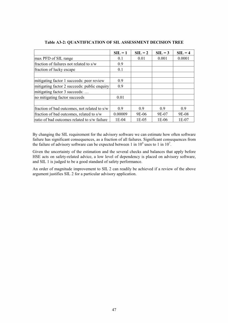
47
Table A3-2: QUANTIFICATION OF SIL ASSESSMENT DECISION TREE
SIL = 1 SIL = 2 SIL = 3 SIL = 4 max PFD of SIL range 0.1 0.01 0.001 0.0001 fraction of failures not related to s/w 0.9 fraction of lucky escape 0.1 mitigating factor 1 succeeds: peer review 0.9 mitigating factor 2 succeeds: public enquiry 0.9 mitigating factor 3 succeeds: … no mitigating factor succeeds 0.01 fraction of bad outcomes, not related to s/w 0.9 0.9 0.9 0.9 fraction of bad outcomes, related to s/w 0.00009 9E-06 9E-07 9E-08 ratio of bad outcomes related to s/w failure 1E-04 1E-05 1E-06 1E-07
By changing the SIL requirement for the advisory software we can estimate how often software failure has significant consequences, as a fraction of all failures. Significant consequences from the failure of advisory software can be expected between 1 in 104 uses to 1 in 107.
Given the uncertainty of the estimation and the several checks and balances that apply before HSE acts on safety-related advice, a low level of dependency is placed on advisory software, and SIL 1 is judged to be a good standard of safety performance.
An order of magnitude improvement to SIL 2 can readily be achieved if a review of the above argument justifies SIL 2 for a particular advisory application.

Printed and published by the Health and Safety ExecutiveC30 1/98
Printed and published by the Health and Safety ExecutiveC1.25 3/02

CRR 419
£10.00 9 780717 623044
ISBN 0-7176-2304-1