continued optical sensor operations in a … · continued optical sensor operations . in a laser...
TRANSCRIPT

[[NOTE
AIR WAR COLLEGE
AIR UNIVERSITY
CONTINUED OPTICAL SENSOR OPERATIONS
IN A LASER ENVIRONMENT
by
William J. Diehl, CDR, USN
A Research Report Submitted to the Faculty
In Partial Fulfillment of the Graduation Requirements
16 February 2011
DISTRIBUTION A. Approved for public release: distribution unlimited

DISCLAIMER
The views expressed in this academic research paper are those of the author and do not reflect
the official policy or position of the US government or the Department of Defense. In accordance
with Air Force Instruction 51-303, it is not copyrighted, but is the property of the United States
government.

Contents
Disclaimer………………………………………………………………………….…….....i
Contents…………………………………………………………………………….……...ii
Illustrations……………………………………………………………………………..….iii
Biography…………………………………………………………………………..……....iv
Introduction………………………………………………………………………….….….1
Optical Region of the Electromagnetic Spectrum….………..……………………….….…2
Introduction to Lasers……………………………..………………………………….…....2
Focal Plane Arrays…………………………………………………………………………3
Future Air and Space Vehicle Regimes…..…………….………………….……………..10
Analysis of Optical Sensor Vulnerabilities to Lasers…………………………………….12
Recommendations………………………….……………………………………….……20
Conclusion………………………………………………………………………………..22
Bibliography……………………………………………………………………………...24

Illustrations
Page
Figure 1. Regions of atmospheric absorption………………….………………………….…….2
Figure 2. Charge Coupled Device…………………………………...………………….….……4
Figure 3. Semiconductors arranged by band gap to cover EO/IR spectrum .………………….6
Figure 4. LANDSAT 7 focal plane design……..………………………………………….……7

Biography
Upon graduating from Duke University, Commander Diehl was commissioned in the
Navy as a Surface Warfare Officer. He served on USS Savannah (AOR 4) and USS Peterson
(DD 969) before joining the Navy Information Warfare community. After training at Defense
Language Institute, Commander Diehl completed tours as an airborne evaluator in the EP-3E
aircraft while stationed at Naval Security Group Activity (NSGA) Misawa, Japan, and as
Executive Officer at NSGA Bahrain. Commander Diehl attended the Naval Postgraduate School
where he earned a Master of Science Degree in Electrical Engineering. He then served on the
staff of the Commander, U.S. Atlantic Fleet and later as the Theodore Roosevelt Carrier Strike
Group cryptologist, where he deployed to the Arabian Gulf in support of Operations Iraqi
Freedom and Enduring Freedom. He has recently completed assignments on the staffs of the
Chief of Naval Operations and Commander, U.S. SEVENTH Fleet.

Introduction
The U.S. and other nations are developing laser (i.e., “light amplification by stimulated
emission of radiation”) applications, including High-energy Lasers (HEL) and Low-energy
Lasers (LEL). While HELs will likely have military applications in Ballistic Missile Defense
(BMD), Counter-Air, Counter-Space, and Counter-Intelligence, Surveillance, and
Reconnaissance (ISR); HEL applications will be slow to proliferate to many potential adversaries
due to high cost and technical complexity. However, LELs will be developed as technological
byproducts of HELs and commercial applications, and will rapidly proliferate, even to resource-
constrained actors, due to low cost and reduced technical complexity.
By 2030, the Air Force will field air and space vehicles which will use focal plane arrays
(FPAs) as optical sensors. This paper will argue that these sensitive FPAs will be vulnerable to
LEL attack, which as LELs proliferate, could render the USAF’s sensing technologies
ineffective. Further, this paper also argues that the Air Force must continue to investigate the
effects of lasers on FPA sensors, to better understand how to protect them and then invest in the
technologies to permit continued operation of all FPA sensors in future hostile environments.
To explore this thesis, this paper begins by introducing the basic theory of lasers and
focal plane arrays. It then discusses the regimes of future Air Force sensor operations, and
analyzes the factors which could facilitate denial of optical sensors using LELs. This paper then
looks at the basic methods of sensor protection against laser illumination, and makes
recommendations for the Air Force to retain use of optical sensors in a proliferated LEL
environment.

Optical Region of the Electromagnetic Spectrum
This research concentrates on effects in the visible and adjacent regions of the
electromagnetic (EM) spectrum, as these are where FPAs provide imagery. These regions
include the ultraviolet (UV) from 10 – 400 nm; visible, or electro-optical (EO) from 0.4 – 0.7
µm; the near infrared (NWIR) from 0.7 – 3.0 µm; mid-wave IR (MWIR) from 3.0 – 6.0 µm; and
the long-wave IR (LWIR) from 6.0 – 15.0 µm in the EM spectra. The actual usable IR spectrum
is discontinuous and less than depicted above, due to various regions of atmospheric absorption
(Figure 1).1
Figure (1) - Regions of atmospheric absorption2
Introduction to Lasers
A laser uses an energy source to excite electrons in an active medium to produce a high-
energy output of coherent light within a narrow frequency range. Ideal characteristics for lasers
are high directionality and low divergence (i.e., narrow beam width), high polarization (i.e.,
1 Adamy, David, EW 102 A Second Course in Electronic Warfare, Artech House, Boston , MA, 2004, 79-98
2 Ibid., 81. Percentage of atmospheric transmittance is shown on the vertical axis, while wavelength is shown on the
horizontal axis. Note that atmospheric transmittance is high in the 400 nm to 2.5µm region (visible and near-IR), 3.0 – 5.0
µm (middle-IR), and 8.0 – 14 µm (far-IR) regions [the areas on the chart where the graph is at its highest]. These are the
spectral regions in which imaging sensors, including focal plane arrays, are most likely to be effective.

electric and magnetic field vectors on the EM wave front are aligned and synchronous), low
diffraction (i.e., very little spreading of the wave front from the laser aperture), efficiency (i.e.,
high ratio of output power to input power), low jitter (i.e., high reproducibility from pulse to
pulse), and high intensity (i.e., power density on target, in Watts/cm²).3 One could also add
practical factors such as cost, safety, size, portability, durability, and availability. To date, no
one laser design has maximized all of the above factors, which explains the wide variety of lasers
in use today and projected for the future. Optimally, one wants to transmit the necessary amount
of energy to the target to achieve the desired effect in the desired amount of time.
Lasers are used in a variety of commercial and military applications. Commercial
applications include welding, fabrication, biomedical, ophthalmology, dentistry, spectroscopy,
environmental mapping, and telecommunications.4 Several key areas of modern research which
are advancing the study of lasers are fiber-optics, free-space laser communications, uranium
enrichment, and controlled nuclear fusion.5 Military applications include distance measurement,
defensive countermeasures against EO/IR guided missiles, target illumination, HELs for ballistic
missile defense and counter-air. The wide variety and utility of commercial and military lasers
indicate that the development of lasers which can threaten our sensors is highly probable.
Focal Plane Arrays
Focal plane arrays, or FPAs, are the current and emerging technology for sensing and
target detection in the EO, IR, and UV spectra. As explained further below, FPAs utilize the
photoelectric effect to detect photonic energy. This is important, as virtually every major sensor
3 O’Shea, Donald, Callen, Russell and Rhodes, William, Introduction to Lasers and Their Applications, Addison-
Wesley Publishing Company, Redding, MA, 1977; Nielsen, Philip, Effects of Directed Energy Weapons, Directed Energy
Professional Society, Albuquerque, NM, 2009 4 Harry, John, Industrial Lasers and Their Applications, McGraw Hill, London, 1974
5 O’Shea, Donald, Callen, Russel and Rhodes, William, Introduction to Lasers and Their Applications, Addison-
Wesley Publishing Company, Redding, MA, 1977

in our battlespace uses this phenomenon to let the warfighter “see” what is going on in the
battlespace. This is true for sensors in the visual spectrum, as well as the UV and IR spectral
areas defined above. 6
Many FPAs use charge-coupled devices (CCD) which consists of arrays of semi-
conductor optical receivers designed to detect photonic quanta. Each cell of the array detects a
quantum of light energy, and clocks the result to the next cell. The result represents the total
original image at the output of the CCD. Figure (2) shows how images are captured on a CCD
and then transmitted to a temporary storage area, where subsequent light measurements are
integrated in order to detect very minute signals.7
Figure (2) – Charge Coupled Device (CCD)8
FPAs are fabricated using very-large scale integrated circuit (VLSI) technology.
Therefore FPAs, like all VLSI circuits, with time tend to decrease in size and increase in
6 Photons, which are packets of electromagnetic energy, strike a semi-conducting surface which liberates electrons. The
energy of the electrons released is proportional to the energy of the photons and can be measured by applying a back bias
(negative voltage) to a collector plate. 7 This is not significantly different than how the digital camera on a cell phone works. Each element of the CCD
captures the appropriate quanta of photonic energy, and within this very sensitive system, these photons are processed to
become the image that we call pictures, or in the latest generations of phones- movies. The same is true for military
sensors over a battlefield. 8 Image of Charged Coupled Device, http://en.wikipedia.org/wiki/File:EMCCD2_color_en.svg (accessed 16 January
2011)

complexity in accordance with Moore’s Law. In current FPAs, the photosensitive detectors are
arranged in linear arrays of pixels, where the detector resolution is defined by the spacing
between the pixels. Modern CCDs have detector spacing on the order of 5-10 µm, and contain
between 5,000 to 10,000 elements per scan line.9 These basic criteria determine the performance
of the imaging sensor. For example, ground resolution is a function of pixel size, focal length,
and altitude, and is expressed by
(1)
The swath of one scan line is a function of the number of pixels and the ground resolution:
(2)
The photonic energy is a function of frequency and wavelength and is expressed by
(3)
Where E is the band-gap in electron volts (eV), h is Planck’s constant 4.136 × 10⁻¹⁵
eV · s, c is
the speed of light 3.0 × 10
8 m/s, and is the light wavelength in meters. For example, the
photonic energy of blue light, which has a wavelength of 435.8 nm, is 2.85 eV.10
The choice of material for the semi-conductor is determined by the desired receiver
wavelength, as the band gap energy (eV) of the semi-conductor must correspond to the energy of
the photon. For example, the band gap of Silicon is 1.12 eV, which is most efficient at 1.1 µm
and which corresponds to the visible and near-IR band.11
The MWIR and LWIR regions require semi-conductors such as Indium Antimonide
(InSb) or Mercury Cadmium Telluride (HgCdTe). As the band gaps in these regions are
9 Olsen, R.C. Remote Sensing from Air and Space, SPIE Press, Bellingham WA, 2007, 79
10 Ibid., 39
11 Ibid., 76
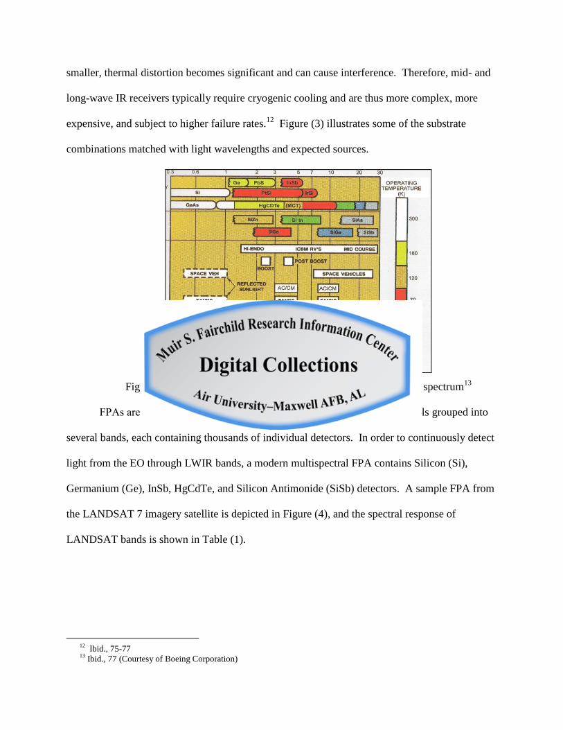
smaller, thermal distortion becomes significant and can cause interference. Therefore, mid- and
long-wave IR receivers typically require cryogenic cooling and are thus more complex, more
expensive, and subject to higher failure rates.12
Figure (3) illustrates some of the substrate
combinations matched with light wavelengths and expected sources.
Figure (3) – Semiconductors arranged by band gap to cover EO/IR spectrum13
FPAs are usually “multispectral” and consist of semi-conducting materials grouped into
several bands, each containing thousands of individual detectors. In order to continuously detect
light from the EO through LWIR bands, a modern multispectral FPA contains Silicon (Si),
Germanium (Ge), InSb, HgCdTe, and Silicon Antimonide (SiSb) detectors. A sample FPA from
the LANDSAT 7 imagery satellite is depicted in Figure (4), and the spectral response of
LANDSAT bands is shown in Table (1).
12
Ibid., 75-77 13
Ibid., 77 (Courtesy of Boeing Corporation)

Figure (4) – LANDSAT 7 focal plane design14
Band Spectrum (µm) Type Band Spectrum (µm) Type
1 0.45-0.52 EO 5 1.55-1.75 NWIR
2 0.52-0.60 EO 6 10.4-12.5 LWIR (thermal)
3 0.63-0.69 EO 7 2.08-2.35 NWIR
4 0.76-0.90 NWIR 8 0.50-0.90 Panchromatic
Table (1) – LANDSAT 7 focal plane bands and spectral response15
Optical sensors are subject to degradation and destruction from both natural and man-
made sources. As the physical dimensions of integrated circuits decrease with improved design,
lithography and fabrication technologies; voltage, currents, resistances, and capacitances also
decrease; thus increasing device complexity and increasing the impact of outside disturbances on
proper operation. Is important to understand some of the ways in which integrated circuits can
fail. Some of these failure mechanisms are outlined below:
14
Ibid., 124. IFOV is “Instantaneous Field of View,” which is a common measure of spatial resolution of a remote
imaging system. An IFOV of 42.6 µrad is equal to 2.44 × 10⁻³
°. 15
Sweetman, Bill, ed., Jane’s Space Systems and Industry 2007-2008, Jane’s Information Group, Alexandria, VA,
2007, ISBN B9780 710628138, 276

Non-destructive failure
Some failure mechanisms in ICs cause only temporary degradation. Each FPA
component, including detector, amplifier, filter, and converter, has an established dynamic range
(i.e., the difference between the smallest and largest signals which can be processed). Photonic
energy which is stronger than the maximum detector range will drive a corresponding transistor
above the linear (i.e., useful device range) and into saturation (i.e., non-useful device range). If
not attenuated, non-linear detector outputs would drive down-stream components into saturation
as well. Properly designed ICs are unlikely to sustain permanent damage if components are
capable of attenuation. Additionally, excessive thermal noise margins and spurious “latch-up”
caused by transient currents or voltages can require device reset, but do not necessarily cause
catastrophic failure of ICs. The effects that cause these failures are also known as “soft” or
“reversible.”16
Destructive failure
The majority of failure mechanisms in ICs are catastrophic (i.e., permanent device
failure). These include Fowler-Nordheim Tunneling, drain punch-through, impact ionization
(i.e., “hot electron effect”), and thermal runaway. The effects that cause destructive failures are
also called “hard” and “non-reversible.”17
Many of the above mechanisms have remedies which
are applied at VLSI foundries, such as grounding connections, guard rings and internal short
circuit protection – all of which increase the size, complexity, and cost of the device.
16
Olsen, Richard, Introduction to the Space Environment, Naval Postgraduate School, Monterey, CA, January 2005,
230 17
Ibid., 230

Extensively grounded substrates, in particular, are required for space-hardening of ICs against
ionizing radiation.18
Although understanding the effects radiation on FPAs (particularly space-borne) has long
been a subject of study, research in understanding the effects of intentional laser radiation on
FPAs, as well as the protection of FPAs against lasers, is a relatively immature field. Some
recent examples of this type of research include examining radiation effects in Indium Gallium
Arsenide (InGaAs) FPAs, radiation hardening for IR-detecting FPAs, extending the frequency
response for space-based FPA in the UV and Near-IR, and using Dynamic Sunlight Filters (DSF)
to increase dynamic range in high-light intensity.19
In one analysis of laser-dazzling effects on
IR FPAs, Schleijpen showed how pulsed lasers produce non-linear degradations in detector
response, which are not easily characterized and are difficult to predict.20
In another analysis,
Hueber et al. identified transient and permanent degradations to an InSb FPA detector when
irradiated by an in-band semi-conductor laser, and also attempted to qualify the “dazzling
efficiency” of a laser on an FPA. Possible parameters used to qualify dazzling efficiency
18
Weste, Neil and Eshraghian, Kamran, Principles of CMOS VLSI Design (2nd
ed.), Addison, Wesley and Longman
Publishing Company, Redding, MA, 1994; Sedra, Adel and Smith, Kenneth, Microelectronic Circuits (4th ed.), Oxford
University Press, NY, 1998 19
Frederick Knight, Matthew Waldon, Brian Greensmith, Michael Mattei, Lado Tonia, Nicholas Gould, MIT Lincoln
Laboratory, Lexington, MA USA 02420-9185, “Radiation Effects in Two InGaAs Focal Plane Arrays,” Grycewicz,
Thomas, Marshall, Cheryl, Warren, Penny, eds., Focal Plane Arrays for Space Telescopes III, Vol. 6690, International
Society for Optics and Photonics (SPIE), Bellingham, WA, 12 September 2007, ISBN 9780819468383; M. S. Lee, Y. S.
Lee, H. C. Lee, Korea Advanced Institute of Science and Technology (Korea, Republic of), “Radiation hardening of low-
noise readout integrated circuit for infrared focal plane arrays,” International Society for Optics and Photonics (SPIE)
Defense Security and Sensing Conference, Conference 7660-129 Poster Session, Orlando, FL, April 2010; Y. Bai, S. G.
Bernd, J. R. Hosack, M. C. Farris, J. T. Montroy, J. Bajaj, Rockwell Scientific Company, 5212 Verdugo Way, Camarillo,
CA 93012, “Hybrid CMOS Focal Plane Array with Extended UV and NIR; Response for Space Applications,” Grycevicz,
Thomas, McCreight, Craig, eds., “Focal Plane Arrays for Space Telescopes,” Vol. 5167, International Society for Optics
and Photonics (SPIE), Bellingham, WA, 12 January 2004, ISBN 9780819450401; A. Donval, T. Fisher, G. Blecher, B.
Nemet, M. Oron, KiloLambda Technologies, Ltd. (Israel), “Dynamic Sunlight Filter (DSF): a passive way to increase the
dynamic range in Visible and SWIR cameras,” International Society for Optics and Photonics (SPIE) Defense Security
and Sensing Conference, Conference 7660-67, Session 10, Orlando, FL, April 2010, “Optical systems, sensors and
cameras, are susceptible to saturation or damage caused by high power of light impinging them. This light source can be a
high power laser, or other light sources, such as the sun. This problem calls for a device that will switch off the
propagating power when the maximal allowed power is exceeded.” 20
Schleijpen, Ric (TNO Defence, Security, and Safety The Hague, The Netherlands), “Laser dazzling of infrared focal
plane array cameras,” SPIE Press, International Society for Optics and Photonics (SPIE), Bellingham, WA, 26 March
2008

included the number of saturated pixels, the decrease in Signal-to-Noise Ratio (SNR), the loss of
image contrast, and the impact on pattern recognition. The authors concluded that “even though
some studies in the open literature show the vulnerability of imaging systems to laser dazzling,
the diversity of analysis criteria employed does not allow the results of these studies to be
correlated.”21
For example, a continuous wave laser degraded pattern recognition of the target
image to a greater degree than an equivalent pulsed laser, and the increase of laser fluence on the
detector did not linearly increase the image degradation.22
The above studies illustrate the point
that the effects of intentional laser radiation on FPAs are not well understood.
To summarize the above, modern EO, IR, and UV imaging sensors are FPAs, which
consist of complex arrays of thousands of elements of solid-state optical detectors in multiple
sensing bands. There are many ways to disrupt these sensitive electronics. Laser irradiance is
one way to temporarily deny or permanently damage FPA sensors, and the complete effects of
intentional laser irradiation on sensitive sensors are not well understood.
Future Air and Space Vehicle Regimes
While precise UAV roadmaps are constantly in flux due to changing requirements,
planning assumptions and budgetary constraints, the Air Force, as well as the other military
21
N. Hueber, Institut Franco-Allemand de Recherches de Saint-Louis (France); D. Vincent, Defence Research and
Development Canada (Canada); A. Dieterlen, Univ. de Haute Alsace (France); A. Morin, Defence Research and
Development Canada (Canada); P. Raymond, Institut Franco-Allemand de Recherches de Saint-Louis (France), “Analysis
and quantification of laser-dazzling effects on IR focal plane arrays”, International Society for Optics and Photonics
(SPIE) Defense Security and Sensing Conference, Conference 7660-124 Session 19, Orlando, FL, April 2010, “The first
study gives accurate results on InSb photocell behaviors when irradiated by a picosecond MWIR laser. With an increasing
peak power density, four different successive responses appear: linear, logarithmic, decreasing ones and permanent linear
offset response. Moreover, we show how the decreasing response of the most irradiated pixels spreads toward the
surrounding pixels of the array.” 22
Hueber, N., Vincent, D., Morin, A., Dieterlen, A., Raymond, P., “Analysis and Quantification of laser dazzling-
effects on IR focal plane arrays,” aISL, DivII/ATC/ELSI, 5 rue du General Cassagnou, Saint-Louis, FRANCE 68300;
bDRDC-Valcartier, 2459 Pie-XI Blvd North, Quebec, QC, CANADA G3J 1X5; cMIPS UHA, 61 rue Albert Camus,
Mulhouse, FRANCE 68200, http://pubs.drdc.gc.ca/PDFS/unc00/p533547_A1b.pdf (accessed 16 January 2011), “Four
analysis criteria were presented that allow global characterization of dazzled images: the number of saturated pixels, the
SNR of unsaturated image portions, the ratio of contrast transfer function in dazzled image to contrast transfer function in
a reference normal image and, finally,the degree of pattern recognition. Their application on dazzled images confirms that
short laser pulses induce less perturbation than CW laser.”
services and government agencies, will be operating a panoply of remotely piloted and
autonomous air and space vehicles during the 2030-2040 timeframe. These vehicles will operate
in three basic regimes: near-earth, near-space, and space. The near-earth vehicles will continue
to consist of the highly successful RQ-4 “Global Hawk,” MQ-1 “Predator” and MQ-9 “Reaper”
variants and follow-on series. They will be joined by vertical take-off air vehicles such as the
MQ-8 “Fire Scout,” Aurora “Golden Eye,” AeroVironment “Sky Tote,” and by at least one fully
autonomous unmanned combat aerial system (UCAS), such as the Boeing X-45C “Phantom
Ray” and/or Northrop Grumman X-47 “Pegasus.”23
The near-space regime will be populated by
a host of new vehicles as a more economic alternative to space, and will consist of High Altitude
Long Endurance (HALE) UAVs, High Altitude Airships (HAA – also called “pseudo-lites”), and
tethered aerostats.24
Although the U.S. present and future space orders of battle are classified,
one can surmise that there will be a host of earth-sensing commercial imagery satellites between
2030-2040, such as the National Polar Orbiting Environmental Satellite System (NPOESS), the
NASA Lewis and Clark Hyper-spectral Imagery (HSI) satellites, French SPOT25
satellites,
Israeli Earth Remote Observation Satellite (EROS), and China – Brazil Earth Resources Satellite
(CBERS).26
23
Daly, Mark and Streetly, Martin, eds., Jane’s Unmanned Aerial Vehicles and Targets Issue 33, Jane’s Information
Group, Alexandria, VA, 2009; “Global Hawk UAV Program Audit Report (F2004-002-FC3000)”, Air Force Audit
Agency, 21 October 2003; “Unmanned Aerial Vehicles, Changes in Global Hawk’s Acquisition Strategy are Required to
reduced program risks,” U.S. General Accounting Office (GAO-05-6), Report to Chairman, Subcommittee on Tactical
Air Land Services Committee and Armed Services Committee House of Representatives, November 2004; Peacock,
Lindsay and Von Rosenbach, Alexander, eds., Jane’s World Air Forces Issue 32, Jane’s Information Group, Alexandria,
VA, 2010, ISSN: 1748 2526 24
Mark and Streetly, Martin, eds., Jane’s Unmanned Aerial Vehicles and Targets Issue 33, Jane’s Information Group,
Alexandria, VA, 2009 25
Olsen, R.C. Remote Sensing from Air and Space, SPIE Press, Bellingham WA, 2007, 128, “Systeme Probatoire
d’Observation de la Terre” 26
Sweetman, Bill, ed., Jane’s Space Systems and Industry 2007-2008, Jane’s Information Group, Alexandria, VA,
2007, ISBN B9780 710628138; Osborne, William, ed., Space Systems Forecast: Satellites and Spacecraft, Forecast
International, Newtown, CT, 2007

These remotely piloted and autonomous aerial and space vehicles will perform a wide
variety of functions across the spectrum of warfare, including offensive and defensive counter
air, targeting, close air support, ISR, and communications. The preponderance of vehicles in all
three regimes will be IMINT capable, and will use FPA imaging sensors, such as the L-3
Communications Sonoma MX-12D Skyball II and Sonoma 494 high altitude EO/IR imaging
system.27
Government research and development organizations are also focusing on low size,
weight and power (SWaP) FPAs for micro-UAV applications, including non-cooled LWIR
sensors.28
Analysis of Optical Sensor Vulnerability to Lasers
In the preceding paragraphs, we have shown that there are a variety of commercial and
military laser applications. We have also seen that the FPA is a complex instrument which is
vulnerable to natural and man-made phenomena, and that FPA-based imaging sensors will be
employed on an increasing number of air and space platforms in various regimes with respect to
distance from the earth. While there has been extensive research on the use of HELs for target
destruction, it remains to be seen whether LELs can be militarized to deny or degrade FPA
sensors on air and spacecraft. The following paragraphs will analyze the dangers to optical
sensors posed by low-energy lasers.
LEL versus HEL
Much of the discussion is dependent on the definition of LEL versus HEL. There is no
absolutely correct delineation – the difference depends on the source, the intended target, and the
desired effect. For example, one possible demarcation is “destruction” (HEL) versus
27
Sonoma 494 High Altitude EO/IR Imaging System and MX-12D Skyball II Small, Lightweight Turret and
Specifications, L-3 Communications Sonoma EO, Santa Rosa, CA, 2005, www.L-3Com.com/SonomaEO (accessed 16
January 2011) 28
Dumas, Melanie, “Tactical Aircraft to Increase Long Wave Infrared Nighttime Detection (TAILWIND),” Defense
Advanced Research Programs Agency (DARPA) Information Processing Techniques Office, Industry Day, 1 May 2009

“degradation” (LEL). By this definition, industrial lasers (such as CO2 lasers), operating in the
10-20 kW range, cut through titanium at 3500 mm/min.29
However, this destructive effect takes
place at a distance of 10 cm, and is not practical at ranges of tens – hundreds of km, due to target
tracking, beam divergence, diffraction and atmospheric effects. In another example, one could
state that LEL are those lasers marketed to the public as “recreational” (i.e., “non-professional”),
which historically were those lasers marketed at ANSI Class 3 and below.30
However, 1.5 W
lasers are now marketed to the general public as “recreational” and the effects of these lasers are
sufficiently threatening to aircraft that the U.S. Congress has debated new regulations and
increased legal oversight.31
An additional delineation between HELs and LELs is that high
powered (i.e., 10 – 100 MW) weapon-class lasers are subject to a non-linear atmospheric effect
called thermal blooming, where atmospheric absorption creates additional refraction. In low-
powered lasers, the characteristics of the transmitted radiation have little effect on the
atmosphere.32
Given the above, the best definition of “low-energy laser” (LEL), for the purposes of this
paper, is a laser which has industrial or scientific uses, is commercially available, has a
continuous power output of less than 10 kW, and is not subject to non-linear atmospheric
absorption effects.
29
Ready, John, Industrial Applications of Lasers, Academic Press, Inc., New York, 1978, 414 30
Laser Safety Standard, American National Standards Institute (ANSI) Z136.1, 2007,
http://en.wikipedia.org/wiki/laser_safety (accessed 25 November 2010), “Class 3B have a maximum power of 500W in
the 315 nm to LWIR, 30 mJ between 400-700 nm, and can cause damage to the human eye.” 31
Bart Elias, “Lasers Aimed at Aircraft Cockpits: Background and Possible Options to Address the Threat to Aviation
Safety and Security,” Congressional Research Service (CRS) Report for Congress, Order Code RS22033, Library of
Congress, Washington, D.C., 26 January 2005 32
Parenti, Ronald, Kingston, Robert and Higgs, Charles, “High-energy Lasers and Laser Propagation,” Lincoln
Laboratory Journal, Vol. 13 No. 1 2002, Lexington, Massachusetts, 2002, 229-230

Tracking and Targeting
The susceptibility of an FPA sensor to laser countermeasures varies according to the
regime in which it is operating. For example, in the near earth regime, the sensor is close to the
earth and laser source (less than 60,000 ft), but is maneuvering with non-deterministic motion;
often at high accelerations relative to the laser. In the near space regime, the sensor is further
from the earth (60,000 to 100,000 ft) but is stationary or quasi-stationary, with only minute
motion relative to the laser. In the space regime (considered to be low-earth orbit in this
research), the sensor is much further from the earth (600 – 1000 km) and is moving at a high rate
of speed across the sky, up to 18°/sec depending on altitude.33
However, the path of the sensor is
determined by orbital mechanics and is highly predictable.
One factor in estimating susceptibility of FPA sensors to lasers is the adversary’s ability
to track the target. The laser must continuously illuminate the sensor - either for tens of seconds
to damage a sensor; or indefinitely, if the desired effect is to deny use of the sensor. For the
space regime, all nations with a space-launch capability in the 2030-2040 timeframe should be
assumed to have the ability to continuously direct a low-power laser at a LEO satellite.
Although one cannot be certain that that non-state actors will have this capability in 2030-2040,
commercially-available equipment already allows amateur astronomers to track satellites in low-
earth orbits.34
Open-source satellite tracking optics, combined with the evolving field of laser
33
Andersen, Geoff, The Telescope (Its History, technology, and Future), Princeton University Press, Princeton, NJ,
2007, 158 34
Meade LX-400 ACF Telescope Specifications Sheet, Meade Instruments Corporation, Irvine, CA, 2008,
http://www.meade.com/lx400-acf/index.html (accessed 13 February 2011), “Current Earth satellite orbital data (including
the International Space Station, Space Shuttle, etc.) may be downloaded; the telescope then automatically acquires and
tracks the satellite at the correct tracking rate.”; Moore, Patrick, ed., The Modern Amateur Astronomer, Springer-Verlag,
London, 1995; Andersen, Geoff, The Telescope (Its History, technology, and Future), Princeton University Press,
Princeton, NJ, 2007, Astronomical telescopes track stars in sidereal time, which is 15°/hour. However, satellite prediction
services are plentifully available on the world-wide web.

communications, could result in high-precision laser satellite tracking equipment becoming
available to the commercial market.
Continuous laser illumination of an FPA on an aircraft in the near earth regime is, and
will remain, a challenging technical problem in the 2030-2040 timeframe. NATO allies lead the
world in technologies to track highly-maneuvering targets using LEL. Some examples are the
AN/AAQ-24 Directional Infrared Countermeasure (DIRCM) and follow-on LAIRCM (Large
Aircraft IR Countermeasure), which direct IR lasers at an attacking missile.35
Russia, France,
Germany, Sweden, and Israel also produce a large range of directional laser warning systems,
electro-optic fire control devices, and laser rangefinders which could be adapted to continuous
laser illumination.36
Non-state actors will have difficulty acquiring this technology in a
legitimate venue as there is no commercial market for EO/IR tracking of highly maneuverable
targets.
FPA sensors are most susceptible to laser countermeasures in the near space regime.
Stationary tethered aerostats, “quasi-stationary” high altitude airships at 65,000 ft, and pseudo-
lites operating below 90 knots at 70,000 ft will provide lucrative targets for ground-based LEL.37
Aircraft operating in this regime are not likely to be operated in high-threat airspace, as they are
vulnerable to high-altitude SAM(s) and counter-air threats. They will likely be operated over
lawless and ungoverned areas, where they will provide persistent surveillance against non-state
actors. Their imaging sensors, however, could be susceptible to laser disruption by non-state
actors.
35
Dardine, Andrew, ed., DMS Market Intelligence Reports (Electronic Warfare), Forecast International, Inc.,
Newtown, CT, 2010 36
Streetly, Martin, ed., Jane’s Radar and Electronic Warfare Systems 2007-2008, Jane’s Information Group,
Alexandria, VA 2007, ISBN 13 9780 7106 28114; Ross, John, ed., Jane’s Special Report: Future Land Battlefield –
Weapons and Doctrine for the 21st Century, Jane’s Information Group, Alexandria, VA, 1999, ISBN 07106 13806
37 Daly, Mark and Streetly, Marti, eds., Jane’s Unmanned Aerial Vehicles and Targets Issue 33, Jane’s Information
Group, Alexandria, VA, 2009

One of the key limitations of achieving high laser intensity (W/cm2) on a target at long
distances (10s – 100s of km) is the scintillation effect caused by atmospheric turbulence. The
solution to this technical challenge is adaptive optics. Adaptive optics are complex and
expensive. They require an auxiliary laser to sample the atmosphere and provide environmental
information to a wave front phase computer, which in turn activates tens of thousands of micro-
hydraulic actuators on a deformable mirror, varying the surface from 1 – 10 µm every
millisecond.38
The potential growth of free-space laser communications, however, could
reinvigorate commercial research and development (R&D) in adaptive optics. This could
catalyze the proliferation of technology which could improve the ability of smaller states and
non-state actors to track and engage distant targets with LEL.39
Empirical Analysis of the Danger of Sensor Saturation by LEL
The following brief empirical analysis shows the vulnerability of FPAs to LEL saturation
effects. Each individual detector cell must be extremely sensitive to detect its target energy at
great distances. For example, the formula for radiated power for a blackbody (i.e., naturally
radiating) source is
(4)
Where σ is the Stefan-Boltzmann constant (5.67 × 10⁻⁸
W/m2·°K
4), ε is emissivity (where an
emissivity of 1 signifies a perfect blackbody), and T is the temperature of the source in degrees
Kelvin (°K).40
The source radiations of objects in the visible bands are assumed to perfectly
38
Nielsen, Philip, Effects of Directed Energy Weapons, Directed Energy Professional Society, Albuquerque, NM,
2009, 126-127 39
Parenti, Ronald, Kingston, Robert and Higgs, Charles, “High-energy Lasers and Laser Propagation,” Lincoln
Laboratory Journal, Vol. 13 No. 1 2002, Lexington, Massachusetts, 2002, 248 40
Olsen, Richard, Remote Sensing from Air and Space, SPIE Press, Bellingham WA, 2007, 46

reflect solar radiation, which averages 1367 W/m2
at the equator.41
Table (2) shows the source
radiation intensities at several wavelengths of interest.
Temperature (°K) 900 500 300 Visible Reflection
max 3µ 6µ 10µ 600 nm
Total radiation (W/m2) 3.7 × 10
5 3500 500 1400
Table (2) – Radiation levels of selected sources
Free-space propagation losses, which are assumed to be isotropic, are given by the formula
(5)
Where s is the distance in meters.42
A logarithmic method of computing 1/s2 propagation losses
is as follows:
Ls (dB) = 32.4 + 20 log10 (km) + 20 log10 (MHz)43
(6)
Using equations (5) and (6), Table (3) shows the corresponding propagation losses in dB and the
resultant power levels at the sensor at a given distance from the source. Note that this calculation
does not take into account scattering or absorption effects.
5km
(dBW)
5km
(W/m2)
10km
(dBW)
10 km
(W/m2)
25 km
(dBW)
25 km
(W/m2)
800 km
(dBW)
800km
(W/m2)
600
nm
-189 1.3×10⁻¹⁹
-194 4.0×10⁻²⁰
-217 2.0×10⁻²²
-247 2.0×10⁻²⁵
3µ -179 1.6×10⁻¹⁸
-185 3.2×10⁻¹⁹
-207 2.0×10⁻²¹
-237 2.0×10⁻²⁴
6µ -166 2.5×10⁻¹⁷
-172 6.3×10⁻¹⁸
-194 4.0×10⁻²⁰
-224 4.0×10⁻²³
10µ -150 1.0×10⁻¹⁵
-156 2.5×10⁻¹⁶
-178 1.6×10⁻¹⁸
-208 1.6×10⁻²¹
Table (3) – Power levels at a detector with distance from the source as indicated
The above power levels illustrate the potential vulnerability of optical sensors to
saturation or non-destructive laser effects. Although LEL might not have sufficient intensity on
41
Olsen, Richard, Introduction to the Space Environment, Naval Postgraduate School, Monterey, CA, January 2005 42
Gordon, Gary and Morgan, Walter, Principles of Communication Satellites, John Wiley & Sons, Inc., New York,
1993 43
Adamy, David, EW 101 A First Course in Electronic Warfare, Artech House, Boston , MA, 2001, 12

target to damage an FPA, even small commercially available lasers can cause saturation. For
example, the ideal far-field intensity S (W/m2) of a laser is given by
(7)
Where P (W/m2) is source power, D (m) is the diameter of aperture, z (m) is the distance from
the source, and (m) is the wavelength.44
Calculations of a few notional laser sources are shown
in Table (4). Although the actual laser intensity on target would be less due to scattering,
absorption and non-ideal diffraction, Table (4) shows that even low-energy lasers could produce
intensities greater than 200 dB above the intensity of the desired signal. The result is that FPA-
based optical sensors would be saturated beyond their ability to properly sense light, rendering
them totally unable to perform their intended function.
Type (nm) Power (W) Aperture
(mm)
Intensity at target
(W/m2)
Gain of laser to desired
signal
handheld 532 0.5 1.5 1120 @ 25 km 5.6 × 1024
Industrial
diode
532 100 1.5 223.4 @ 800 km 1.12 × 1027
Industrial CO2 1060 5,000,000
(peak)
25 2.3 × 10⁹ @ 25 km 1.44 × 10
27
Industrial CO2 1060 60 (average) 25 2.7 × 10⁴ @ 25 km 1.69 × 10
22
Table (4) – Ratio of laser intensity to desired signal intensity at specified distance
Threat
Will potential adversaries possess LELs capable of denying and degrading FPA sensors
in the 2030-2040 timeframe? Industrialized nations will certainly have the technical capability.
Russia has been conducting research into high-energy military lasers since the 1960s, and
possesses the tracking and operational capability to employ LEL in a disruptive role. China will
also have this capability, and has possibly already employed ground-based lasers against U.S.
44
Nielsen, Philip, Effects of Directed Energy Weapons, Directed Energy Professional Society, Albuquerque,
NM, 2009, 104-108

satellites; possibly in a laser ranging role but possibly with intent to degrade U.S. space-based
imaging sensors.45
Iran could develop a counter-air and counter-space LEL capability as a by-
product of its self-reliance on arms production, nascent space and ICBM program, and potential
use of lasers to produce highly enriched uranium (HEU). Additionally, many industrialized
nations will produce high-quality commercial lasers which meet or exceed the specifications of
LELs as described above. There is a high probability that a determined actor could build on
high-technology exports from these nations in order to militarize a LEL capability by 2030.
In particular, one should note the aforementioned scenario of autonomous UAVs
operating in the near-space regime. These vehicles will have a long-duration, quasi-stationary
loiter over territories where non-state actors such as Hezbollah, Al Qaeda and associated
movements, FARC, etc. will operate. Proliferation of LELs to hostile non-state actors,
improvements and cost-reductions in optical tracking systems, and technical assistance from a
wealthy patron, could render these high-altitude sensors vulnerable to disruption.
In any case, when non-state actors obtain advanced weapon systems, high-end state
actors are often caught unaware and are forced to alter their battle strategies. Examples include
the proliferation of shoulder-fired anti-helicopter missiles to Islamic militants in Afghanistan
during the Soviet-Afghan War and to the warlords in Somalia in 1993, Hezbollah UAV flights
over Israel in 2004, Explosively Formed Projectiles (EFP) to Iraqi insurgents in 2005, and anti-
ship cruise missiles to Hezbollah in the 2006 Israel-Hezbollah War.46
45
“Satellite Laser Ranging in China,” Union of Concerned Scientists, Cambridge, Mass., 8 January 2007,
http://www.ucsusa.org/nuclear_weapons_and_global_security/space_weapons/technical_issues/chinese-lasers-and-us.html
( accessed 29 November 2010) 46
Hartley, Will, ed., Jane’s World Insurgency and Terrorism, Issue 32, Jane’s information Group, Alexandria, VA
2010, ISSN 1748 2585, 810-811

Recommendations
The two recommendations that result from this research are to continue researching the
effects of lasers on focal plane arrays and to research and implement technologies to protect
sensitive optical sensors from lasers while enabling their continued use in a laser environment.
These recommendations are summarized below:
Research Effects of Lasers on Focal Plane Arrays
As indicated earlier in this report, the effects of intentional laser radiation on focal plane
arrays are not fully understood. While research has shown that even low power lasers can
produce temporary and permanent degradations in sensitive optical detectors, the overall military
utility of “laser dazzling” is not well characterized. The Air Force should continue research into
understanding the parameters of laser effects on FPAs, to include types of damage caused by
different types of lasers, pulsed versus continuous, degradation versus destruction, reversible
versus non-reversible, and disruptive effects as a function of power. Better understanding of the
effects of lasers on FPAs in a battlefield environment will help shape investment decisions for
technologies to preserve friendly use of optical sensors.
Research and Implement Protection Technologies
Given the danger that LELs pose to continuous operation of optical sensors, the Air Force
should invest in technologies that attenuate or filter lasers while permitting continued viewing, or
“look-through.” Attenuation and filtering are two technologies that could negate or mitigate the
laser threat to sensitive FPA optics.
Many of the historical laser protection techniques involve attenuation of arriving energy
to avoid damage. For example, mechanical shutters can be used to close the optical aperture in
response to laser irradiation. However, mechanical shutters are undesirable, as they result in
successful sensor denial. Additional attenuation techniques include automatic gain control
(AGC) and electro-optic modulators, both of which reduce resulting voltages in the detector
elements.47
Laser radiation attenuation gas chambers, which consist of chambers of energy-
absorbing gas adjacent to the focal plane array surface, are also being investigated as ways to
protect sensitive optics against lasers.48
Another possibility is the use of Carbon Nanotube
(CNT)-based optical limiters to provide a broadband limiting response from visible to long-wave
IR.49
Attenuation techniques can protect sensitive circuits against voltage spikes and thermal
overload, but could reduce the detector’s sensitivity and performance.
Filtering techniques offer another path to achieving maximum sensor performance in a
laser environment, as these techniques protect sensitive FPAs from laser radiation while
minimizing reductions in sensor sensitivity and performance. Traditional laser filtering
technologies include neutral density filters, optical interference filters, and semi-conductor
attenuators.50
Modern spatial and adaptive filtering techniques, however, offer additional
possibilities. Spatial filters, which use coherent light and diffraction characteristics to remove
random fluctuations from the intensity profile of arriving light, are now implemented as digital
signal processing (DSP) algorithms due to improvements in processing speed.51
Digitally-
implemented spatial filters are standard features in typical FPA technologies, including both
47
Webb, Colin, and Jones, Julian, Handbook of Laser Technology and Applications: Laser design and laser systems,
Institute of Physics Publishing, The Institute of Physics, London, 2004, 1183-1192 48
Sonstroem, Jaime, “Light Sensor Protection and Method for Protecting a Light Sensor with Laser Radiation
attenuating gas,” U.S. Patent 7485849 B2, 3 February 3 2009 49
Nan He, Yu Chen and Ying Liu, “Carbon Nanotubes and Their Derivatives for Laser Protection,” Department of
Chemistry, Lab for Advanced Materials, East China University of Science and Technology, Shanghai, People’s Republic
of China, Form and Content Media, ltd. , London UK, http://www.fac-media.com/editors/Examples/750.pdf (accessed 17
Jan 2011) 50
Charschan, S. S., ed., Lasers in Industry, Van Nostrand Reinhold Company, New York, 1972, 570-574 51
De Smith, Goodchild, Longley, eds., “Linear Spatial Filtering, Geospatial Analysis - a comprehensive guide (3rd
edition),” Winchelsea Press, University College, London, 2011,
http://www.spatialanalysisonline.com/output/html/Linearspatialfiltering.html (accessed 16 January 2011); “Spatial
Filters,” Newport Corporation, Irvine, CA, 2011, www.newport.com (accessed 16 January 2011)

CCD and Complementary Metal Oxide Semiconductor (CMOS) devices.52
Additionally,
adaptive filters are an advanced field of mathematics, electronics engineering and physics which
could be useful in filtering unwanted laser interference from the desired target signals. Adaptive
filters, such as matched filters, spectral factorization, and subspace methods, are designed to self-
adjust a transform function to conform to continuously changing background characteristics.53
Although adaptive filters have historically been employed in acoustic (e.g., noise cancellation
and sonar) and radio-frequency environments, improvements in electro-optic and signal
processing technology may lend their application to adaptive optical filtering. Multi-spectral
FPAs can be designed with in-band laser detectors, which disable a finite spectrum region but
enable continued processing of the remaining EO/IR spectrum.
Although both attenuation and filtering technologies have merit for preserving friendly
use of optical sensors in a laser environment, it is not practical to choose a single technology
which would be best in all circumstances. Therefore, the Air Force should state the requirement
to implement technologies to negate or mitigate laser effects on focal plane array-based optical
sensors, while continuing to investigate optimal solutions.
Conclusion
The U.S. Air Force, other military services, and other government agencies, will field a
wide variety of unmanned aerial vehicles by 2030. Most will be equipped with focal plane array
-based optical sensors in the ultra-violet, visible, and infra-red spectrum. Low-energy lasers pose
a denial and degradation threat to these sensors. Industrialized nation-states will likely possess
laser-countermeasure capabilities in the 2030-2040 timeframe, capable of preventing use of blue-
52
Norton, Paul, “Detector Focal Plane Array Technology,” U.S. Army Night Vision and Electronics Sensor
Directorate, Fort Belvoir, VA, June 2003 53
Therrien, Charles, Discrete Random Signals and Statistical Signal Processing, Prentice Hall Signal Processing
Series, Upper Saddle River, NJ, 1992

force optical sensors. Non-state actors will likely possess some form of LEL, but could have
difficulty engaging highly-maneuverable near-earth vehicle-based sensors. However, even non-
state actors should be able to deny optical sensors on near-space platforms. Improvements in
commercial astronomy, laser communications, adaptive optics, and other industrial applications
will improve non-state actor capabilities to employ LEL. The Air Force should state
requirements for continued optical sensor operations in a laser environment, and should
implement this protection in all future optical sensor arrays intended for near-space platforms (as
a threshold) and for all remaining platforms (as an objective). The Air Force should also
continue research on the disruptive effects of laser radiation on FPAs and the most cost effective
way of attenuating or filtering in-band lasers while preserving the remainder of the spectrum for
friendly use.

Bibliography
Adamy, David, EW 101 A First Course in Electronic Warfare, Artech House, Boston , MA,
2001
Adamy, David, EW 102 A Second Course in Electronic Warfare. Artech House, Boston MA,
2004
Andersen, Geoff, The Telescope (Its History, technology, and Future), Princeton University
Press, Princeton, New Jersey, 2007
Bai, Y., Bernd, S. G., Hosack, J. R., Farris, M. C., Montroy, J. T. and Bajaj, J., “Hybrid CMOS
Focal Plane Array with Extended UV and NIR,” Rockwell Scientific Company, 5212
Verdugo Way, Camarillo, CA 93012, “Response for Space Applications,” Grycevicz,
Thomas, McCreight, Craig, eds., Focal Plane Arrays for Space Telescopes, Vol. 5167,
International Society for Optics and Photonics (SPIE), Bellingham, WA, 12 January
2004, ISBN 9780819450401
Charschan, S. S., ed., Lasers in Industry, Van Nostrand Reinhold Company, New York, 1972
Daly, Mark and Streetly, Martin, eds., Jane’s Unmanned Aerial Vehicles and Targets Issue 33,
Jane’s Information Group, Alexandria, VA, 2009
Dardine, Andrew, ed., DMS Market Intelligence Reports (Electronic Warfare), Forecast
International, Inc., Newtown, CT, 2010
De Smith, Goodchild, Longley, eds., “Linear Spatial Filtering, Geospatial Analysis - a
comprehensive guide (3rd edition),” Winchelsea Press, University College, London,
2011, http://www.spatialanalysisonline.com/output/html/Linearspatialfiltering.html
(accessed 16 January 2011); “Spatial Filters,” Newport Corporation, Irvine, CA, 2011,
www.newport.com (accessed 16 January 2011)
Donval, A., Fisher, T., Blecher, G., Nemet, B, Oron, M., “Dynamic Sunlight Filter (DSF): a
passive way to increase the dynamic range in Visible and SWIR cameras,” Kilo Lambda
Technologies, Ltd. (Israel), International Society for Optics and Photonics (SPIE)
Defense Security and Sensing Conference, Conference 7660-67, Session 10, Orlando, FL,
April 2010
Dumas, Melanie, “Tactical Aircraft to Increase Long Wave Infrared Nighttime Detection
(TAILWIND),” Defense Advanced Research Programs Agency (DARPA) Information
Processing Techniques Office, Industry Day 1 May 2009
Elias, Bart, “Lasers Aimed at Aircraft Cockpits: Background and Possible Options to Address
the Threat to Aviation Safety and Security,” Congressional Research Service (CRS)
Report for Congress, Order Code RS22033, Library of Congress, Washington, D.C., 26
January 2005
“Global Hawk UAV Program Audit Report (F2004-002-FC3000)”, Air Force Audit Agency, 21
October 2003
Gordon, Gary and Morgan, Walter, Principles of Communication Satellites, John Wiley & Sons,
Inc., New York, 1993
Hartley, Will, ed., Jane’s World Insurgency and Terrorism, Issue 32, Jane’s information Group,
Alexandria, VA 2010, ISSN 1748 2585
Harry, John, Industrial Lasers and Their Applications, McGraw Hill, London, 1974
Hueber, N., Institut Franco-Allemand de Recherches de Saint-Louis (France); Vincent, D.,
Defence Research and Development Canada (Canada); Dieterlen, A., Univ. de Haute
Alsace (France); Morin, A., Defence Research and Development Canada (Canada);

Raymond, P., Institut Franco-Allemand de Recherches de Saint-Louis (France),
“Analysis and quantification of laser-dazzling effects on IR focal plane arrays,”
International Society for Optics and Photonics (SPIE) Defense Security and Sensing
Conference, Conference 7660-124 Session 19, Orlando, FL, April 2010
Hueber, N., Vincent, D., Morin, A., Dieterlen, A., Raymond, P., “Analysis and Quantification of
laser dazzling-effects on IR focal plane arrays,” aISL, DivII/ATC/ELSI, 5 rue du General
Cassagnou, Saint-Louis, FRANCE 68300; bDRDC-Valcartier, 2459 Pie-XI Blvd North,
Quebec, QC, CANADA G3J 1X5; cMIPS UHA, 61 rue Albert Camus, Mulhouse,
FRANCE 68200, http://pubs.drdc.gc.ca/PDFS/unc00/p533547_A1b.pdf (accessed 16
January 2011)
Image of Charged Coupled Device, http://en.wikipedia.org/wiki/File:EMCCD2_color_en.svg
(accessed 16 January 2011)
Knight, Frederick, Waldon, Matthew, Greensmith, Brian, Mattei, Michael, Tonia, Lado and
Gould, Nicholas, “Radiation Effects in Two InGaAs Focal Plane Arrays,” MIT Lincoln
Laboratory, Lexington, MA USA 02420-9185, Grycewicz, Thomas, Marshall, Cheryl,
Warren, Penny, eds., Focal Plane Arrays for Space Telescopes III, Vol. 6690,
International Society for Optics and Photonics (SPIE), Bellingham, WA, 12 September
2007, ISBN 9780819468383
Laser Safety Standard, American National Standards Institute (ANSI) Z136.1, 2007,
http://en.wikipedia.org/wiki/laser_safety (accessed 25 November 2010)
Lee, M. S., Lee, Y. S. and Lee, H. C., “Radiation hardening of low-noise readout integrated
circuit for infrared focal plane arrays,” Korea Advanced Institute of Science and
Technology (Korea, Republic of), International Society for Optics and Photonics (SPIE)
Defense Security and Sensing Conference, Conference 7660-129 Poster Session, Orlando,
FL, April 2010
Meade LX-400 ACF Telescope Specifications Sheet, Meade Instruments Corporation, Irvine,
CA, 2008, http://www.meade.com/lx400-acf/index.html (accessed 13 February 2011)
Moore, Patrick, ed., The Modern Amateur Astronomer, Springer-Verlag, London, 1995
MX-12D Skyball II Small, Lightweight Turret Specifications, L-3 Communications Sonoma EO,
Santa Rosa, CA, 2005, www.L-3Com.com/SonomaEO (accessed 16 January 2011)
Nan He, Yu Chen and Ying Liu, “Carbon Nanotubes and Their Derivatives for Laser
Protection,” Department of Chemistry, Lab for Advanced Materials, East China
University of Science and Technology, Shanghai, People’s Republic of China, Form and
Content Media, ltd. , London UK, http://www.fac-media.com/editors/Examples/750.pdf
(accessed 17 Jan 2011)
Nielsen, Philip, Effects of Directed Energy Weapons, Directed Energy Professional Society,
Albuquerque, NM, 2009
Norton, Paul, “Detector Focal Plane Array Technology,” U.S. Army Night Vision and
Electronics Sensor Directorate, Fort Belvoir, VA, June 2003
Olsen, Richard, Introduction to the Space Environment, Naval Postgraduate School, Monterey,
CA, January 2005
Olsen, R.C., Remote Sensing from Air and Space, SPIE Press, Bellingham WA, 2007
Osborne, William, ed., Space Systems Forecast: Satellites and Spacecraft, Forecast International,
Newtown CT, 2007
O’Shea, Donald, Callen, Russel and Rhodes, William, Introduction to Lasers and Their
Applications, Addison-Wesley Publishing Company, Redding, MA, 1977

Parenti, Ronald, Kingston, Robert and Higgs, Charles, “High-energy Lasers and Laser
Propagation,” Lincoln Laboratory Journal, Vol. 13 No. 1 2002, Lexington,
Massachusetts, 2002
Peacock, Lindsay and Von Rosenbach, Alexander, eds., Jane’s World Air Forces Issue 32, Jane’s
Information Group, Alexandria, VA 2010, ISSN: 1748 2526
Ready, John, Industrial Applications of Lasers, Academic Press, Inc., New York, 1978
Ross, John, ed., Jane’s Special Report: Future Land Battlefield – Weapons and Doctrine for the
21st Century, Jane’s Information Group, Alexandria, VA, 1999, ISBN 07106 13806
“Satellite Laser Ranging in China,” Union of Concerned Scientists, Cambridge, MA, 8 January
2007,
http://www.ucsusa.org/nuclear_weapons_and_global_security/space_weapons/technical_
issues/chinese-lasers-and-us.html (accessed 29 November 2010)
Sedra, Adel and Smith, Kenneth, Microelectronic Circuits (4th
ed.), Oxford University Press,
New York, 1998
Schleijpen, Ric (TNO Defence, Security, and Safety, The Hague, The Netherlands), “Laser
dazzling of infrared focal plane array cameras,” SPIE Press, Bellingham, WA, 26 March
2008
Sonoma 494 High Altitude EO/IR Imaging System Specifications, L-3 Communications Sonoma
EO, Santa Rosa, CA, 2005, www.L-3Com.com/SonomaEO (accessed 16 January 2011)
Sonstroem, Jaime, “Light Sensor Protection and Method for Protecting a Light Sensor with
Laser Radiation attenuating gas,” U.S. Patent 7485849 B2, 3 February 3 2009
Streetly, Martin, ed., Jane’s Radar and Electronic Warfare Systems 2007-2008, Jane’s
Information Group, Alexandria, VA 2007, ISBN 13 9780 7106 28114
Sweetman, Bill, ed., Jane’s Space Systems and Industry 2007-2008, Jane’s Information Group,
Alexandria, VA, 2007, ISBN B9780 710628138
Therrien, Charles, Discrete Random Signals and Statistical Signal Processing, Prentice Hall
Signal Processing Series, Upper Saddle River, NJ, 1992
“Unmanned Aerial Vehicles, Changes in Global Hawk’s Acquisition Strategy are Required to
reduced program risks,” U.S. General Accounting Office (GAO-05-6), Report to
Chairman, Subcommittee on Tactical Air Land Services Committee and Armed Services
Committee House of Representatives, November 2004
Webb, Colin, and Jones, Julian, Handbook of Laser Technology and Applications: Laser design
and laser systems, Institute of Physics Publishing, The Institute of Physics, London,
2004, 1183-1192
Weste, Neil and Eshraghian, Kamran, Principles of CMOS VLSI Design (2nd
ed.), Addison,
Wesley and Longman Publishing Company, Redding, MA, 1994