construction specification for - · pdf fileconstruction specification for concrete...
TRANSCRIPT
ONTARIO PROVINCIAL STANDARD SPECIFICATION
METRICOPSS 904
JANUARY 1995
CONSTRUCTION SPECIFICATION FOR CONCRETE STRUCTURES
TABLE OF CONTENTS 904.01 SCOPE 904.02 REFERENCES 904.03 DEFINITIONS 904.04 SUBMISSION AND DESIGN REQUIREMENTS 904.04.01 Mix Design
.02 Submissions 904.04.02.01 General
.02 Work Plan
.03 Concrete Strengths 35 MPa and Greater
.04 Cold Weather Concreting
.05 Hot Weather Concreting
.06 Field Curing, Handling and Delivery of Cylinders
.07 Curing Compound
.08 Spray Equipment - Curing Compound
.09 Concrete Delivery Ticket
.10 Bearings 904.05 MATERIALS 904.05.01 Concrete
.02 Portland Cement
.03 Sand
.04 Bonding Agents 904.05.04.01 Cement Paste
.02 Cement-Sand
.03 Latex Modified 904.05.05 Latex Modifier
.06 Sand-Cement Mortar
.07 Non-Shrink Grout
.08 Steel Reinforcement and Mechanical Connections
.09 Epoxy Coated Steel Reinforcement and Epoxy Coated Mechanical Connections
Page 1 Rev. Date: 01/1995 OPSS 904
904.05.10 Deck Joint Assemblies and Joint Materials .11 Burlap .12 Moisture Vapour Barrier .13 Curing Compound .14 Approach Slab Seat Elastomer .15 Insulation Material .16 Cylinder Moulds
904.06 EQUIPMENT 904.06.01 General
.02 Placing Equipment 904.06.02.01 Concrete Pump 904.06.03 Consolidating Equipment
.04 Mixer for Bonding Agents
.05 Finishing Equipment 904.06.05.01 Finishing Machine
.02 Screed Rails
.03 Screed Rail Chairs
.04 Work Bridges 904.06.06 Hand Finishing Equipment
.07 Straight Edges
.08 Tremie
.09 Spray Equipment for Curing Compound
.10 Compressor - Air Blasting
904.07 CONSTRUCTION 904.07.01 Formwork and Falsework
.02 Steel Reinforcement
.03 Concrete 904.07.03.01 General
.02 Miscellaneous Hardware
.03 Concrete on Granular Base
.04 Placing 904.07.03.04.01 General .02 Permission to Place Concrete .03 On-Site Transportation .04 Placing Operations Over New Concrete .05 Consolidation 904.07.03.05 Curing Unformed Surfaces 904.07.03.05.01 General .02 Structure Decks .03 Curing with Burlap and Water .04 Curing with Moisture Vapour Barrier .05 Curing with Curing Compound
Page 2 Rev. Date: 01/1995 OPSS 904
904.07.03.06 Curing Formed Surfaces .07 Hot Weather Concreting
904.07.03.07.01 Concrete Placing Temperature .02 Placing Restrictions 904.07.03.08 Cold Weather Concreting 904.07.03.08.01 Concrete Placing Temperature .02 Placing Restrictions .03 Protection - General .04 Protection - Minimum Requirements .05 Housing and Heating .06 Temperature Records .07 Withdrawal of Protection 904.07.03.09 Abrasive Blast Cleaning
.10 Construction Joints 904.07.03.10.01 General .02 Surfaces Requiring Abrasive Blast Cleaning .03 Surface Preparation .04 Bonding Agents at Joints 904.07.03.11 Surface Finish - Unformed Surfaces 904.07.03.11.01 General .02 Surface Tolerance 904.07.03.12 Surface Finish - Formed Surfaces 904.07.03.12.01 General .02 Exposed Surfaces .03 Surface Tolerance 904.07.03.13 Alignment of Components
.14 Removal of Formwork and Falsework
.15 Field Sampling and Testing of Concrete 904.07.03.15.01 General .02 Sampling and Testing - Slump, Air Content and Temperature .03 Frequency of Testing .04 Preparing Test Cylinders .05 Delivery of Test Cylinders .06 Testing for Uniformity of Mixed Concrete .07 Aggregate Discharge Test .08 Concrete Strengths 35 MPa or Greater .09 Testing for Early Strength 904.07.04 Tremie Concrete 904.07.05 Concrete in Footings
.06 Concrete in Structure and in Deck
.07 Parapet and Barrier Walls
.08 Concrete in Approach Slabs
Page 3 Rev. Date: 01/1995 OPSS 904

.09 Concrete in Slope Paving
.10 Dowels into Concrete and into Rock 904.08 QUALITY ASSURANCE 904.08.01 General
.02 Acceptance
.03 Curing Compound 904.09 MEASUREMENT FOR PAYMENT 904.09.01 General
.02 Actual Measurement 904.09.02.01 Concrete in Culverts
Mass Concrete Tremie Concrete Concrete in Footings Concrete in Barrier Wall Footings
.02 Dowels into Concrete Dowels into Rock
904.09.03 Plan Quantity Measurement 904.09.03.01 Concrete in Culverts
Mass Concrete Tremie Concrete Concrete in Footings Concrete in Barrier Wall Footings
.02 Dowels into Concrete Dowels into Rock
904.09.04 Non Measurement 904.09.04.01 Concrete in Structure
Concrete in Substructure Concrete in Substructure and Retaining Walls Concrete in Deck Concrete in Barrier Walls Concrete in Parapet Walls Concrete in Approach Slabs Concrete in Slope Paving
904.10 BASIS OF PAYMENT 904.10.01 General 904.10.01.01 Concrete in Culverts - Item
Mass Concrete - Item Tremie Concrete - Item Concrete in Footings - Item Concrete in Barrier Wall Footings - Item Concrete in Structure - Item Concrete in Substructure - Item Concrete in Substructure and Retaining Walls - Item
Page 4 Rev. Date: 01/1995 OPSS 904
Concrete in Deck - Item Concrete in Barrier Walls - Item Concrete in Parapet Walls - Item Concrete in Approach Slabs - Item Concrete in Slope Paving - Item
904.10.02 Dowels into Concrete - Item
Dowels into Rock - Item .03 Formwork and Falsework .04 Chemical Admixtures .05 Working Slabs .06 Deck Joint Assemblies and Bearings .07 Reinforcing Steel and Other Steel Reinforcement
904.01 SCOPE This specification covers the requirements for the construction of concrete structures. 904.02 REFERENCES This specification refers to the following standards, specifications or publications: Ontario Provincial Standard Specifications, Construction: OPSS 128 General Specification for the Supply of Materials from Designated Sources OPSS 501 Compacting OPSS 905 Concrete Reinforcement OPSS 919 Formwork and Falsework OPSS 920 Deck Joint Assemblies, Waterstops, Joint Fillers, Joint Seals and Joint Sealing
Compounds - Structures OPSS 922 Installation of Bearings OPSS 928 Structure Rehabilitation - Concrete Removal OPSS 929 Abrasive Blast Cleaning - Concrete Construction OPSS 930 Structure Rehabilitation - Concrete Patches and Overlays Ontario Provincial Standard Specifications, Material: OPSS 1002 Aggregates - Concrete OPSS 1202 Bearings - Elastomeric Plain and Steel Laminated OPSS 1301 Cementing Materials OPSS 1305 Moisture Vapour Barrier OPSS 1306 Burlap OPSS 1312 Latex Modifiers for Use in Portland Cement Concrete OPSS 1315 White Pigmented Curing Compounds for Concrete OPSS 1350 Concrete Materials and Production OPSS 1440 Steel Reinforcement for Concrete OPSS 1442 Epoxy Coated Steel Reinforcement for Concrete
Page 5 Rev. Date: 01/1995 OPSS 904
Canadian Standards Associations Standard: CAN/CSA A23.1-M90 - Concrete Materials and Method of Concrete Construction CAN/CSA A23.2-M90 - Methods of Test for Concrete CSA A283-1980 - Qualification Code for Concrete Testing Laboratories American Society for Testing and Materials: ASTM D4285-83, 1988 - Method for Indicating Oil or Water in Compressed Air 904.03 DEFINITIONS For the purpose of this specification, the following definitions apply: Bridge: means a structure which provides a roadway, carriageway or walkway for the passage of vehicles and/or pedestrians across an obstruction or gap or facility and which is greater than 3 metres in span. Cold Weather: means those conditions when the air temperature is at or below 5°C. It is also considered to exist when the air temperature is at or is likely to fall below 5°C within 96 h after concrete placement. Temperature refers to shade temperature. Cold Joint: means the interface surface other than at a formed joint which occurs when plastic concrete is placed against concrete which has taken its initial set. Culvert: means a structure which provides an opening through an embankment and in which roadway loads are distributed to the structure through fill or which is designated as a culvert in the contract. Designated Limits: means the dimensions of the component as shown on the plans or the limits of the component as revised in the field, in writing by the Contract Administrator. Hot Weather: means those conditions when the air temperature is at or above 28°C. It is also considered to exist when the air temperature is at or is likely to rise above 28°C within 24 h. Temperature refers to shade temperature. Miscellaneous Hardware: means a fabrication required to complete a component as shown on the plans that is not otherwise included in another tender item. "R" Value: means the metric thermal resistance value m2. °C/W per 1 mm of thickness, which is a measurement of the resistance to heat transfer of insulation. Structure: means any bridge, culvert, tunnel, retaining wall, wharf, dock or guideway. Tremie: means a hopper with a vertical pipe extending from the bottom, used to place concrete under water. Tremie Concrete: means concrete placed by means of a tremie.
Page 6 Rev. Date: 01/1995 OPSS 904
904.04 SUBMISSION AND DESIGN REQUIREMENTS 904.04.01 Mix Design The Contractor shall be responsible for the concrete mix design, except for the mix used in latex modified concrete overlays which the Owner will design. The quantity of chemical admixtures added shall be at least the specified minimum dose in conformance with OPSS 128. 904.04.02 Submissions 904.04.02.01 General The submissions for concrete mix design data and the certificate of ready mixed concrete facilities and/or the certificate of mobile mix concrete production facilities shall be supplied as required in OPSS 1350. 904.04.02.02 Work Plan Two weeks prior to commencement of placing concrete in bridge decks and placing concrete from new concrete, complete details of all equipment and the proposed methods and sequence of placing operations to be used on the Contract for that operation, including the location of transporting and placing equipment when placed on new concrete, shall be provided to the Contract Administrator. 904.04.02.03 Concrete Strengths 35 MPa and Greater When trial batches are not required to be made, the evidence qualifying the ready mix plant to supply the required class of concrete without trial batching shall be submitted to the Contract Administrator 30 d prior to placing the concrete. 904.04.02.04 Cold Weather Concreting Two weeks prior to beginning contract work under cold weather concreting conditions, details of the proposed cold weather protective measures shall be submitted in writing to the Contract Administrator. The submission shall be accompanied by samples of insulation if requested by the Contract Administrator. The proposal shall contain the following information: a. weather conditions for which the proposals apply; b. type of insulation, "R" value and number of layers including test data supporting the "R" value: c. i. number and capacity of heaters;
ii. capacity of fuel tanks; iii. layout of heaters, fuel lines and fuel tanks; iv. design of housing;
d. method of withdrawal of protection; e. method of ensuring cold weather protection measures are maintained when work requiring
adjustment to the protective measure is being performed. f. method of curing of concrete, if method of curing is not included as part of the cold weather protection
system.
Page 7 Rev. Date: 01/1995 OPSS 904
904.04.02.05 Hot Weather Concreting One week prior to the commencement of concrete production, in hot weather, the details of the method to be used in the production of the concrete, to control the concrete temperature, shall be submitted to the Contract Administrator. 904.04.02.06 Field Curing, Handling and Delivery of Cylinders One week prior to commencement of concrete work, complete details of the method of field curing, handling and delivery of the test cylinders shall be provided to the Contract Administrator. 904.04.02.07 Curing Compound One week prior to the application of the curing compound, literature specifying the manufacturer's recommended rate of application shall be submitted to the Contract Administrator. 904.04.02.08 Spray Equipment - Curing Compound One week prior to the application of the curing compound a description of the equipment to be used, including a statement from the manufacturer of the curing compound approving the equipment, shall be submitted to the Contract Administrator. 904.04.02.09 Concrete Delivery Ticket One copy of the concrete delivery ticket shall be submitted to the Contract Administrator for each load of concrete delivered. 904.04.02.10 Bearings Two weeks prior to placing concrete in the substructure, the dimensions of bearings, bearing seat elevations, and the required adjustments to the reinforcing steel shall be submitted to the Contract Administrator. 904.05 MATERIALS 904.05.01 Concrete Concrete shall conform to the requirements of OPSS 1350. 904.05.02 Portland Cement Portland Cement shall conform to OPSS 1301. 904.05.03 Sand Sand shall conform to OPSS 1002.
Page 8 Rev. Date: 01/1995 OPSS 904

904.05.04 Bonding Agents 904.05.04.01 Cement Paste Cement paste bonding agent shall consist of Portland Cement Type 10 and sufficient water to produce a consistency such that it can be applied with a stiff brush, to the existing concrete, in a thin even coating that will not run or puddle. 904.05.04.02 Cement-Sand Cement-sand bonding agent shall consist of Portland Cement Type 10 and sand in the ratio of 1.0:1.0 by volume and sufficient water to produce a consistency such that it can be applied with a stiff brush, to the existing concrete, in a thin even coating that will not run or puddle. 904.05.04.03 Latex Modified Latex modified bonding agent shall consist of Portland Cement Type 10, latex modifier and sand in the ratio of 1.0: 0.5: 2.0 by volume and sufficient water to produce a consistency such that it can be applied with a stiff brush, to the existing concrete, in a thin even coating that will not run or puddle. 904.05.05 Latex Modifier Latex modifier shall conform to OPSS 1312. 904.05.06 Sand-Cement Mortar Sand-cement mortar shall be a 2:1 mixture by volume of sand and Portland Cement Type 10 and shall contain 12 percent entrained air, with sufficient water, to make a stiff mix. 904.05.07 Non-Shrink Grout Non-shrink grout shall conform to OPSS 128. 904.05.08 Steel Reinforcement and Mechanical Connections Steel reinforcement shall conform to OPSS 1440. Mechanical connectors shall conform to OPSS 905. 904.05.09 Epoxy Coated Steel Reinforcement and Epoxy Coated Mechanical
Connections Epoxy coated steel reinforcement shall conform to OPSS 1442. Epoxy coated mechanical connectors shall conform to OPSS 905. 904.05.10 Deck Joint Assemblies and Joint Materials Deck joint assemblies, joint fillers, joint seals, joint sealing compounds and external waterstops shall conform to OPSS 920. 904.05.11 Burlap Burlap shall conform to OPSS 1306.
Page 9 Rev. Date: 01/1995 OPSS 904
904.05.12 Moisture Vapour Barrier Moisture vapour barrier shall be white, opaque, polyethylene film, at least 100 µm thick conforming to OPSS 1305. 904.05.13 Curing Compound Curing compound shall conform to OPSS 1315. 904.05.14 Approach Slab Seat Elastomer The approach slab seat elastomer shall conform to the plain bearing requirements of OPSS 1202, except that the size shall be as specified on the Contract drawings. 904.05.15 Insulation Material Insulation material shall be mineral wool, glass fibre, plastic foam or other suitable material, having an "R" value not less than 0.02 m2. °C/W per 1 mm thickness. Straw insulation shall not be used. Loose or absorbent insulation material shall not be used unless it is completely contained within waterproof wrapping. 904.05.16 Cylinder Moulds The moulds shall have a nominal inside diameter of 150 mm and a nominal height of 300 mm. They shall be made of sheet metal or plastic conforming to CAN/CSA A23-2-1D. Plastic moulds shall have plastic lids. The lids shall be chemically and physically compatible with Portland Cement concrete, and shall provide a watertight closure for the moulds. Each sheet metal cylinder mould shall be supplied with a polyethylene bag. The polyethylene bag shall be white opaque polyethylene film at least 50 µm thick. The bag shall be of such dimensions as to provide watertight containment of the concrete filled mould when twisted and tied with a twist tie. 904.06 EQUIPMENT 904.06.01 General Equipment made of aluminum material shall not come in contact with the plastic concrete. 904.06 02 Placing Equipment 904.06.02.01 Concrete Pump The concrete pump shall be a reciprocating pump equipped to fit a pipeline at least 100 mm in diameter.
Page 10 Rev. Date: 01/1995 OPSS 904
904.06.03 Consolidating Equipment Internal vibrators shall be of the high frequency type with 8000 minimum to 12000 maximum vibrations per minute when immersed in concrete. External vibrators shall have a minimum frequency of 3600 vibrations per minute. Internal vibrators used to consolidate concrete components containing epoxy coated steel reinforcement shall have a resilient covering that will not damage the epoxy coated reinforcement during use. 904.06.04 Mixer for Bonding Agents The mixer for the bonding agent shall be a stationary mixer, power driven, and capable of uniformly mixing the materials. 904.06.05 Finishing Equipment 904.06.05.01 Finishing Machine The finishing machine shall: a. be self propelled and capable of forward and reverse movement under positive control; b. be fitted with wheels which travel on adjustable screed rails; c. be fitted with a reversing rotating cylinder screed, capable of finishing the concrete without
subsequent hand finishing; d. be fitted with a reversing power screw auger, e. be capable of externally vibrating the surface of the concrete by means of a plate or roller mounted in
front of the rotating cylinder screed and behind the power screw auger. f. be fitted with a means to raise all screeds to clear the screeded surface and to accurately reposition
them without adjusting the legs; g. have adjustable legs fitted with locking devices; 904.06.05.02 Screed Rails Maximum deflection of the screed rails under load shall be 2 mm in a 1.2 m length. The rails shall be straight to within 3 mm in a 3 m length. 904.06.05.03 Screed Rail Chairs Screed rail chairs shall be adjustable in height, made of metal and spaced at a maximum of 1.2 m and be placed under all rail joints. 904.06.05.04 Work Bridges Work bridges shall be provided to facilitate surface finishing unscreeded areas, concrete inspection and placing of curing materials. Where placements are longer than 40 m or wider than 10 m, a second work bridge shall be used.
Page 11 Rev. Date: 01/1995 OPSS 904
Work bridges shall ride on screed rails and the top surface of the work bridge shall not be higher than 1.0 m above the finished surface. 904.06.06 Hand Finishing Equipment Floats shall be made of magnesium or wood. Magnesium bull floats shall be commercially made. 904.06.07 Straight Edges Two straight edges commercially made of metal, one 3 m and one 500 mm long shall be used. 904.06.08 Tremie The tremie shall be equipped with a foot valve at the bottom of the pipe. The pipe shall be 300 mm ± 50 mm I.D. and shall be long enough to extend to the lowest point of concrete deposit. 904.06.09 Spray Equipment for Curing Compound The curing compound shall be applied to the concrete surface by the means of motorized spraying equipment approved by the manufacturer of the curing compound. The equipment shall be equipped with an agitator. 904.06.10 Compressor - Air Blasting The compressor for air blasting shall have a minimum capacity of 3.5 m3/minute. The compressed air shall be free of oil or other contaminants when tested in conformance with ASTM D4285. 904.07 CONSTRUCTION 904.07.01 Formwork and Falsework Formwork and falsework shall conform to OPSS 919. Barrier walls shall not be slip formed. 904.07.02 Steel Reinforcement The placing of steel reinforcement shall conform to OPSS 905. Where the superstructure is continuous over a support, the reinforcing steel shall be placed for the entire deck before any concrete is placed. The above requirement does not apply to the bottom slab of post tensioned box voided decks. 904.07.03 Concrete 904.07.03.01 General Unhindered access to the work shall be provided for the purpose of inspection and testing of the concrete and its materials, both at the site of the work and at any plant used for the production of the concrete and its materials. The concrete mix design shall not be altered to accommodate the method of transporting and placing.
Page 12 Rev. Date: 01/1995 OPSS 904
The consistency and air content of the concrete, at the point of discharge from the truck, shall be determined on the basis of slump and air tests conforming to OPSS 1350. Only concrete that meets the specification requirements for the air and slump tests shall be incorporated into the work. The temperature of the concrete at the time of placing shall be between 10° and 28°C. All additions made to the load of concrete, after delivery, shall be recorded on the concrete delivery ticket. When the concrete is delivered by means of agitating or mixing equipment, discharge of the concrete shall be completed within 1.5 h after introduction of the mixing water to the cement and aggregates. When there is an interruption in placing of the concrete greater than 20 min. the unfinished surface of the concrete shall be covered with wet burlap. 904.07.03.02 Miscellaneous Hardware Miscellaneous hardware shall be accurately placed and securely held in position to ensure that it will not be displaced during concrete placement. 904.07.03.03 Concrete on Granular Base Before placing concrete, the granular base shall be dampened immediately ahead of the concrete placement, by means of a uniform spray of water, sufficient to wet the granular base thoroughly without leaving standing water. 904.07.03.04 Placing 904.07.03.04.01 General The method of transporting, placing and consolidating the concrete shall be such as to prevent segregation of the ingredients. Concrete shall be deposited within 1.5 m of its final position. Concrete shall be placed at a steady rate, suitable for the type of construction, such that a monolithic concrete is obtained without the formation of cold joints. When concrete is to be dropped more than 1.5 m fully enclosed vertical drop chutes, extending to the point of deposit, shall be used. Drop chutes are not required for placing concrete in steel tube piles of 0.6 m diameter or less. When concrete is to be placed on a surface that has a slope greater than 3% the placing operation shall begin at the lower end of the slope and progress upwards. Super-plasticizer to facilitate placing shall only be used when specified in the mix design. All curing material required for a concrete placement shall be on the site prior to that concrete placement. Except for tremie concrete, all concrete shall be placed in the dry.
Page 13 Rev. Date: 01/1995 OPSS 904
904.07.03.04.02 Permission to Place Concrete Placing of concrete in the structure shall only commence after the Contractor receives permission to place, in writing from the Contract Administrator, prior to each placing operation. 904.07.03.04.03 On-Site Transportation Runways for buggies shall be of sufficient strength to prevent shaking and jarring of the buggies and reinforcing steel. Concrete placing and transporting devices shall not be supported by the reinforcing steel. Chutes shall have sufficient slope to deliver concrete of the approved consistency and shall have a maximum length of 15 m. 904.07.03.04.04 Placing Operations Over New Concrete Transporting or placing of plastic concrete from new concrete will only be permitted when the new concrete has: a. reached the specified strength; b. completed the specified curing period; and c. been protected where damage to the concrete is liable to occur. 904.07.03.04.05 Consolidation Internal or external vibrators or both shall be used to thoroughly consolidate concrete at the point of deposit within 15 min. of placing. Each layer of concrete shall be vibrated and vibration shall extend into the previous layer to produce a homogeneous mixture at the layer interface. Vibration shall not be used to make the concrete flow or spread into place more than 1.5 m from the point of deposit. 904.07.03.05 Curing Unformed Surfaces 904.07.03.05.01 General All unformed surfaces and slip formed surfaces shall utilize one or more of the following curing methods: a. burlap and water; b. moisture vapour barrier c. white pigmented compound. 904.07.03.05.02 Structure Decks When the ambient air temperature is 0°C or higher at the time of placing, the structure decks shall be cured with burlap and water. When the ambient air temperature is below 0°C at the time of placing, the structure deck shall be cured with moisture vapour barrier. The deck shall be air dried for an additional 72 hours prior to waterproofing. Buried structure decks shall be cured using any of the curing methods detailed in this specification.
Page 14 Rev. Date: 01/1995 OPSS 904

904.07.03.05.03 Curing with Burlap and Water Burlap shall be presoaked by immersing it in water for a period of 24 h immediately prior to placing. Two layers of burlap shall be applied to the surface of the concrete. Strips shall overlap 150 mm and shall be held down without marring the surface of the concrete. The burlap shall be applied immediately after finishing of the concrete surface, from 2 to 4 m from the pan or screed of the finishing machine or from the finishing operation. The burlap shall be maintained in a continuously wet condition throughout the 96 h curing period. The burlap shall be covered with a layer of moisture vapour barrier in a manner which will prevent deformation of the surface of the concrete. Air flow in the space between the moisture vapour barrier and the burlap shall be prevented in conformance with the requirements of curing with moisture vapour barrier. The moisture vapour barrier shall be placed within 12 h following placement of the concrete. 904.07.03.05.04 Curing with Moisture Vapour Barrier A moisture vapour barrier shall be placed immediately after finishing of the concrete surface, from 2 to 4 m of the finishing operation. Air flow in the space between the moisture vapour barrier and the concrete surface shall be prevented. To achieve this the moisture vapour barrier shall be held down at the edges and at all laps, 150 mm minimum, to prevent displacement. The material shall be kept in place for a minimum curing period of 96 h. 904.07.03.05.05 Curing with Curing Compound A curing compound shall not be used: a. on any construction joint; b. when cold weather concreting is in effect; c. on any structure deck; d. on any exposed formed surface. Immediately prior to application, the curing compound shall be agitated by mechanical means to provide a homogeneous mixture. It shall be applied immediately after finishing of the concrete surface, from 2 to 4 m of the finishing operation, completely covering the surface of the concrete. A second application of curing compound shall be applied within 30 to 60 min. after the first application. Each application shall be such that the membrane formed is uniform in thickness and colour and free of breaks and pinholes. The surface shall be maintained in this condition for a minimum period of 7 d. The rate of each application shall not be less than the rate specified by the manufacturer of the compound. 904.07.03.06 Curing Formed Surfaces Curing shall conform to the following: a. where the formwork is left in place for 96 h or more, no additional curing will be required; b. where the formwork is removed in less than 96 h, the concrete shall be cured with burlap and water
for the remainder of the minimum curing period of 96 h. Curing compound shall not be used.
Page 15 Rev. Date: 01/1995 OPSS 904
904.07.03.07 Hot Weather Concreting 904.07.03.07.01 Concrete Placing Temperature The temperature of the concrete at the time of placement shall be between 10°C and 28°C. 904.07.03.07.02 Placing Restrictions The temperature of formwork, reinforcing steel or the material on which the concrete is to be placed, shall not exceed 30°C. When the air temperature exceeds 28°C and the concrete temperature exceeds 25°C, the concrete delivered by means of agitator or truck mixers shall be discharged within 1 h after the introduction of the mixing water. 904.07.03.08 Cold Weather Concreting 904.07.03.08.01 Concrete Placing Temperature The temperature of the concrete at the time of placement shall be between 10°C and 28°C. 904.07.03.08.02 Placing Restrictions Ice and snow shall be removed from the area where concrete is to be placed. Deicing chemicals shall not be used. Concrete shall not be placed on or against frozen ground. Excavations prepared for concreting and any existing concrete, reinforcing steel, structural steel, forms or other surfaces against which concrete will be placed, shall be at a minimum temperature of 5°C for a period of 12 h prior to commencement of placing concrete. All cold weather protection material shall be on site prior to each concrete placement. 904.07.03.08.03 Protection - General The Contractor shall protect the concrete during cold weather. The protection system shall be designed for the worst conditions that can be reasonably anticipated from local weather records, forecasts, site conditions and past experience for the time period during which the protection is required. The Contractor shall monitor the conditions and modify the protection system as required. 904.07.03.08.04 Protection - Minimum Requirements During the seven days following placing, the concrete temperature shall not fall below 10°C or exceed 70°C. For cold weather conditions, protection of concrete shall at least conform to Table 1.
Page 16 Rev. Date: 01/1995 OPSS 904
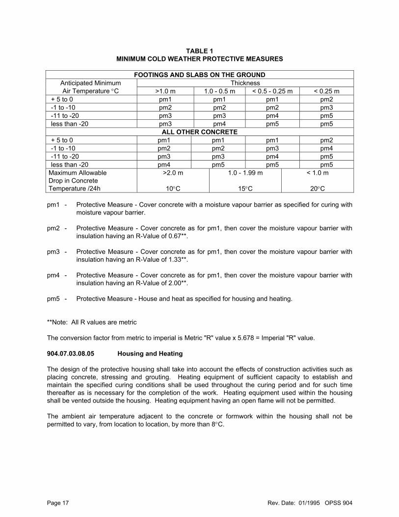
TABLE 1 MINIMUM COLD WEATHER PROTECTIVE MEASURES
FOOTINGS AND SLABS ON THE GROUND
Thickness Anticipated Minimum Air Temperature °C >1.0 m 1.0 - 0.5 m < 0.5 - 0.25 m < 0.25 m
+ 5 to 0 pm1 pm1 pm1 pm2 -1 to -10 pm2 pm2 pm2 pm3 -11 to -20 pm3 pm3 pm4 pm5 less than -20 pm3 pm4 pm5 pm5
ALL OTHER CONCRETE + 5 to 0 pm1 pm1 pm1 pm2 -1 to -10 pm2 pm2 pm3 pm4 -11 to -20 pm3 pm3 pm4 pm5 less than -20 pm4 pm5 pm5 pm5
Maximum Allowable Drop in Concrete Temperature /24h
>2.0 m
10°C
1.0 - 1.99 m
15°C
< 1.0 m
20°C pm1 - Protective Measure - Cover concrete with a moisture vapour barrier as specified for curing with
moisture vapour barrier. pm2 - Protective Measure - Cover concrete as for pm1, then cover the moisture vapour barrier with
insulation having an R-Value of 0.67**. pm3 - Protective Measure - Cover concrete as for pm1, then cover the moisture vapour barrier with
insulation having an R-Value of 1.33**. pm4 - Protective Measure - Cover concrete as for pm1, then cover the moisture vapour barrier with
insulation having an R-Value of 2.00**. pm5 - Protective Measure - House and heat as specified for housing and heating. **Note: All R values are metric The conversion factor from metric to imperial is Metric "R" value x 5.678 = Imperial "R" value. 904.07.03.08.05 Housing and Heating The design of the protective housing shall take into account the effects of construction activities such as placing concrete, stressing and grouting. Heating equipment of sufficient capacity to establish and maintain the specified curing conditions shall be used throughout the curing period and for such time thereafter as is necessary for the completion of the work. Heating equipment used within the housing shall be vented outside the housing. Heating equipment having an open flame will not be permitted. The ambient air temperature adjacent to the concrete or formwork within the housing shall not be permitted to vary, from location to location, by more than 8°C.
Page 17 Rev. Date: 01/1995 OPSS 904

904.07.03.08.06 Temperature Records The Contract Administrator will supply thermocouple wires and/or copper tubing. These thermocouple wires and/or copper tubing shall be installed at locations designated by the Contract Administrator. Access, to permit the Contract Administrator to measure the concrete temperature, shall be provided. The Contractor shall be responsible for any damage to the thermocouple wire and tubing. 904.07.03.08.07 Withdrawal of Protection The cold weather protection shall be gradually removed or reduced in such a manner that the maximum allowable drop of concrete temperature for each 24 h period as specified in Table 1 is not exceeded. The protection shall not be totally removed nor shall the concrete be fully exposed to the air until the average concrete temperature is within 10°C of the air temperature. 904.07.03.09 Abrasive Blast Cleaning Abrasive blast cleaning shall be done in conformance with OPSS 929. The abrasive blast cleaned area of concrete shall receive the next placement of concrete within 48 h or the surfaces shall be reblasted. All existing non-coated reinforcing steel that will be incorporated into the rehabilitation of a concrete structure component and all surfaces of existing structural steel against which new concrete will be placed for the rehabilitation of a concrete structure component shall be abrasive blast cleaned. The extent of cleaning both reinforcing steel and structural steel shall conform to the abrasive blast cleaning of reinforcing steel requirements of OPSS 929. The abrasive blast cleaning of structural steel shall be done immediately prior to placing the coated reinforcing steel. 904.07.03.10 Construction Joints 904.07.03.10.01 General The Contractor shall form construction joints at the locations shown on the contract drawings. A straight 20 mm 'V' groove shall be formed at the exposed face of the concrete at all construction joints. 'V' grooves shall not be used on bridge deck surfaces except for the bottom slab of post tensioned box voided slabs. Concrete shall only be placed against vertical construction joints in barrier walls when the previously placed concrete has cured for at least 96 h. A bulkhead shall be used to form vertical or inclined construction joints.
Page 18 Rev. Date: 01/1995 OPSS 904
904.07.03.10.02 Surfaces Requiring Abrasive Blast Cleaning The following surfaces shall be abrasive blast cleaned. 1. All faces of blockouts in concrete for deck joint assemblies; 2. All faces or recesses in concrete for stressing cable anchorages including the stressing anchorage
surfaces; 3. All construction joint faces between precast segments requiring application of bonding agents; 4. All surfaces of concrete against which new concrete is to be placed in rehabilitation of a concrete
structure component; 904.07.03.10.03 Surface Preparation All construction joint faces shall be sound concrete, free of dirt, grease, dust, laitance and debris. The construction joint shall be air blast cleaned and then wetted for a period of one hour immediately prior to placing the concrete or bonding agent. Excess water shall be removed from the surface using compressed air. 904.07.03.10.04 Bonding Agents at Joints A thin coating of bonding agent shall be brushed onto the prepared surface immediately before placing fresh concrete. All surfaces against which the concrete is to be placed shall receive a thorough, even coating with no excess of bonding agent in any area. Bonding agent not used within 30 minutes of mixing shall be discarded. A cement-sand bonding agent shall be used for: a. Vertical construction joints in concrete deck slabs; b. Blockouts in concrete for installation and modification of deck joint assemblies; c. Stressing tendon anchorage recesses; d. Vertical surfaces of existing concrete against which new concrete is to be placed in the rehabilitation
of concrete components; Bonding agents shall be mixed by means of a mixer. 904.07.03.11 Surface Finish - Unformed Surfaces 904.07.03.11.01 General Finishing of the concrete surface shall be done while it is sufficiently plastic to achieve the desired grades, elevations and texture. The Contractor shall ensure that excessive fines and water are not drawn to the surface. No material shall be applied to the concrete surface to aid in the finishing.
Page 19 Rev. Date: 01/1995 OPSS 904
The surface shall be smooth, free from open texturing, undulations, projections and ridges and shall be struck off true to grade and cross section and, except as specified for bridge deck placements, shall be hand finished with a float. The top surface of sidewalks and curbs shall be given a broomed finish. Bearing seats and deck joint assembly dams shall receive a wood float finish. 904.07.03.11.02 Surface Tolerance Except across the crown or drainage gutters, the surface shall be such that when tested with a 3 m long straight edge placed anywhere in any direction on the surface there shall be no gap greater than 6 mm between the bottom of the straight edge and the surface of the concrete. Across construction joints the gap shall not be greater than 3 mm. All unformed construction joint surfaces forming the underside of sidewalks, curbs, medians and barrier walls shall be such that, when tested with a 500 mm straight edge placed anywhere in any direction on the surface, there is no gap greater than 20 mm between the bottom of the straight edge and the surface of the concrete. 904.07.03.12 Surface Finish - Formed Surfaces 904.07.03.12.01 General Concrete surfaces shall not be treated with cement slurry or paste. Within 3 d following the removal of forms, all holes left in surfaces by the removal of formwork and falsework and air holes which has a dimension greater than 15 mm shall be filled with sand-cement mortar or a non-shrink grout. The holes shall be moist at the time of filling, and the mortar shall be tamped into place. Honey-combing or cavities shall be repaired as follows: 1. Concrete shall be removed in conformance with OPSS 928. 2. Where the resultant cavity has an average depth greater than 100 mm and an area greater than
0.1 m2 it shall be formed and patched with concrete equivalent to that used in the structure. The faces of the cavity shall be abrasive blast cleaned in conformance with the abrasive blast cleaning of concrete surfaces requirements of OPSS 929. The patch shall be placed within 24 h after blast cleaning. Immediately before placing the concrete, the faces of the cavity shall be wetted down for 1h and coated with a sand-cement bonding agent.
3. All other cavities shall be prepared as for the larger cavities and then shall be filled with sand-cement
mortar or non-shrink grout.
The surface of the patch shall be floated to a surface texture to match the adjacent concrete. 4. Patches shall be cured with burlap and water and protected as required for cold weather concreting.
Page 20 Rev. Date: 01/1995 OPSS 904
904.07.03.12.02 Exposed Surfaces The appearance of the concrete shall be uniform as to colour, pattern and texture when viewed from a distance of 15 m. Where a patch is exposed to view, white Portland Cement shall be blended with the normal cement to achieve a uniformity of colour. To ensure this uniformity, trial mixes shall be made beforehand and sample panels compared with the main body of the concrete. The Contractor shall remove all projections such as fins and bulges and all blemishes such as stains and rust marks. 904.07.03.12.03 Surface Tolerance The surface shall be such that when tested with a 3 m long straight edge placed anywhere in any direction on the surface there shall be no gap greater than 6 mm between the bottom of the straight edge and the surface of the concrete. Across construction joints the gap shall not be greater than 3 mm. 904.07.03.13 Alignment of Components The position of the inner and outer top edges of the curb, sidewalk, barrier and parapet wall shall be set true to the elevations, alignment and camber called for on the plans without visible deviation, from one end of the structure to the other, with the following tolerances. The average slope or alignment shall be within 1:400 of that specified and the total variation for the total length of the structure shall not be greater than 40 mm. The allowable surface finish tolerance of the curb, sidewalk, barrier and parapet walls shall be ± 6 mm in any 3 m length when measured with a straight edge. The plumbness shall be within 1:400 of that specified. 904.07.03.14 Removal of Formwork and Falsework The removal of formwork and falsework shall conform to OPSS 919 and the contract drawings. 904.07.03.15 Field Sampling and Testing of Concrete 904.07.03.15.01 General Concrete testing shall be done by personnel certified by the American Concrete Institute at the level of Concrete Field Testing Technician, Grade 1, or by personnel from a testing company certified by the Canadian Standards Association, CSA A283 Category O. Personnel from the CSA certified company shall have passed the CSA examination in concrete field testing that is required for certification. 904.07.03.15.02 Sampling and Testing - Slump, Air Content and Temperature The plastic concrete shall be sampled and field tested for slump, air content and temperature in conformance with OPSS 1350 and the results of these tests recorded. The air meter shall be calibrated at least once a year in conformance with CSA 23.2-4C and the certificate shall be available when requested by the Contract Administrator.
Page 21 Rev. Date: 01/1995 OPSS 904
904.07.03.15.03 Frequency of Testing The minimum frequency of testing shall conform to Table 2 and the samples of the loads shall be taken directly from the load of concrete as directed by the Contract Administrator. 904.07.03.15.04 Preparing Test Cylinders The concrete test cylinders shall be made and cured in conformance with CSA Test Method A.23.2-3C for compressive tests to be performed by the Owner. The cylinders shall be formed in moulds. When sheet metal moulds are used they shall be enclosed in polyethylene bags closed with twist ties immediately after moulding. The Owner will supply forms on which shall be recorded the test information and the individual cylinder identification numbers.
Page 22 Rev. Date: 01/1995 OPSS 904
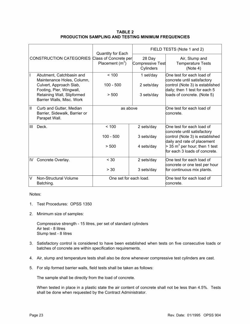
TABLE 2 PRODUCTION SAMPLING AND TESTING MINIMUM FREQUENCIES
FIELD TESTS (Note 1 and 2)
CONSTRUCTION CATEGORIES Quantity for Each
Class of Concrete per Placement (m3)
28 Day Compressive Test
Cylinders
Air, Slump and Temperature Tests
(Note 4)
I Abutment, Catchbasin and Maintenance Holes, Column, Culvert, Approach Slab, Footing, Pier, Wingwall, Retaining Wall, Slipformed Barrier Walls, Misc. Work
< 100
100 - 500
> 500
1 set/day
2 sets/day
3 sets/day
One test for each load of concrete until satisfactory control (Note 3) is established daily; then 1 test for each 5 loads of concrete. (Note 5)
II Curb and Gutter, Median Barrier, Sidewalk, Barrier or Parapet Wall.
as above One test for each load of concrete.
III Deck. < 100
100 - 500
> 500
2 sets/day
3 sets/day
4 sets/day
One test for each load of concrete until satisfactory control (Note 3) is established daily and rate of placement > 35 m3 per hour; then 1 test for each 3 loads of concrete.
IV Concrete Overlay. < 30
> 30
2 sets/day
3 sets/day
One test for each load of concrete or one test per hour for continuous mix plants.
V Non-Structural Volume Batching.
One set for each load. One test for each load of concrete.
Notes: 1. Test Procedures: OPSS 1350 2. Minimum size of samples:
Compressive strength - 15 litres, per set of standard cylinders Air test - 8 litres Slump test - 8 litres
3. Satisfactory control is considered to have been established when tests on five consecutive loads or
batches of concrete are within specification requirements. 4. Air, slump and temperature tests shall also be done whenever compressive test cylinders are cast. 5. For slip formed barrier walls, field tests shall be taken as follows:
The sample shall be directly from the load of concrete.
When tested in place in a plastic state the air content of concrete shall not be less than 4.5%. Tests shall be done when requested by the Contract Administrator.
Page 23 Rev. Date: 01/1995 OPSS 904
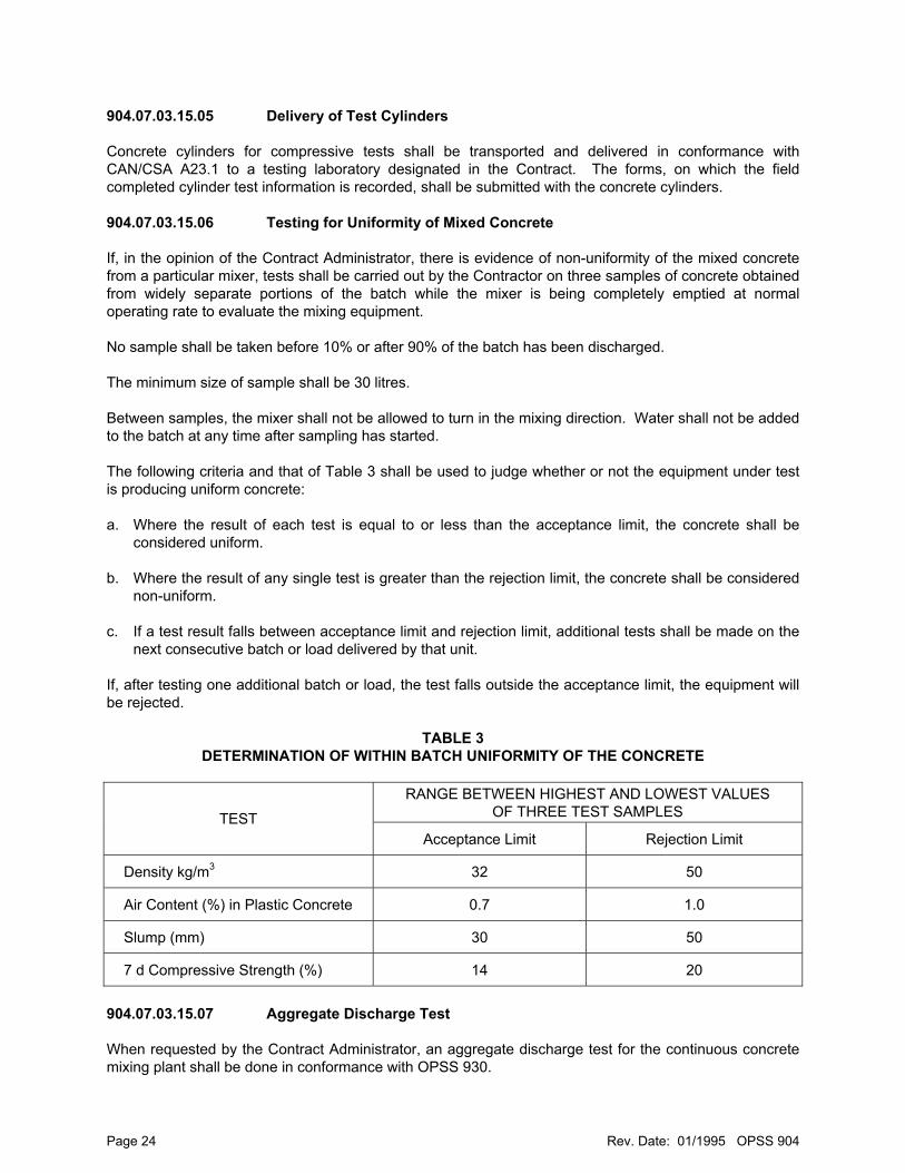
904.07.03.15.05 Delivery of Test Cylinders Concrete cylinders for compressive tests shall be transported and delivered in conformance with CAN/CSA A23.1 to a testing laboratory designated in the Contract. The forms, on which the field completed cylinder test information is recorded, shall be submitted with the concrete cylinders. 904.07.03.15.06 Testing for Uniformity of Mixed Concrete If, in the opinion of the Contract Administrator, there is evidence of non-uniformity of the mixed concrete from a particular mixer, tests shall be carried out by the Contractor on three samples of concrete obtained from widely separate portions of the batch while the mixer is being completely emptied at normal operating rate to evaluate the mixing equipment. No sample shall be taken before 10% or after 90% of the batch has been discharged. The minimum size of sample shall be 30 litres. Between samples, the mixer shall not be allowed to turn in the mixing direction. Water shall not be added to the batch at any time after sampling has started. The following criteria and that of Table 3 shall be used to judge whether or not the equipment under test is producing uniform concrete: a. Where the result of each test is equal to or less than the acceptance limit, the concrete shall be
considered uniform. b. Where the result of any single test is greater than the rejection limit, the concrete shall be considered
non-uniform. c. If a test result falls between acceptance limit and rejection limit, additional tests shall be made on the
next consecutive batch or load delivered by that unit. If, after testing one additional batch or load, the test falls outside the acceptance limit, the equipment will be rejected.
TABLE 3
DETERMINATION OF WITHIN BATCH UNIFORMITY OF THE CONCRETE
RANGE BETWEEN HIGHEST AND LOWEST VALUES OF THREE TEST SAMPLES TEST
Acceptance Limit Rejection Limit
Density kg/m3 32 50
Air Content (%) in Plastic Concrete 0.7 1.0
Slump (mm) 30 50
7 d Compressive Strength (%) 14 20
904.07.03.15.07 Aggregate Discharge Test When requested by the Contract Administrator, an aggregate discharge test for the continuous concrete mixing plant shall be done in conformance with OPSS 930.
Page 24 Rev. Date: 01/1995 OPSS 904
904.07.03.15.08 Concrete Strengths 35 MPa or Greater When approved by the Contract Administrator, the concrete from trial batches made to determine the acceptability of the mix design for concrete with strengths of 35 MPa and greater may be incorporated into parts of the structure that require a lesser strength of concrete. When the source of concrete is a ready mix plant, a trial batch of concrete shall be supplied from each plant used for supplying the concrete. A trial batch shall be delivered to the site of the work and tested. Where access to the site of the work is not possible, the Contract Administrator will designate a suitable location for testing. The following information, for each trial batch, shall be provided to the Contract Administrator for each plant: a. Strength test data from the field trial batch which shall consist of data from tests conducted on at least
one set of standard cylinders tested at 7 d and one set of standard cylinders tested at 28 d. b. The strength test data for mixes with supplementary cementitious materials which shall also include
one set of standard cylinders tested at 3 d. c. The air content, temperature, and slump of concrete used in the trial batch which shall be tested and
recorded. For an acceptable mix, the test cylinders, when tested, shall have an average compressive strength greater than the required strength at such a level above the required strength as to indicate that the concrete will consistently meet the requirements of the strength specification. When adjustments or changes are made to the mix design, further full size trial batches of concrete shall be completed to the satisfaction of the Contract Administrator. When agreed upon with the Contract Administrator, accelerated tests may be used in conformance with OPSS 1350, to predict the 28 d strength of the proposed concrete mix. In lieu of a trial batch the Contract Administrator may accept evidence in conformance with OPSS 1350, that the ready mix plant has been qualified to supply the class of concrete required in this contract to another one of the Owner's contracts within the last 12 months. 904.07.03.15.09 Testing for Early Strength The Contractor shall be responsible for all aspects of the making and transportation of cylinders required for early strength determination such as may be required to permit stressing or stripping of formwork and falsework. A minimum of four sets of cylinders representative of the concrete placed in the structure, at least one set from the start, middle and end of the deck section being placed, shall be cast. All cylinder test results must reach the minimum stressing strength shown on the contract drawings before stressing can commence. The Owner will test reasonable numbers of these cylinders at the laboratory designated in the Contract. 904.07.04 Tremie Concrete Concrete shall be placed using a tremie or a concrete pump. No air or water pockets shall be introduced into the tremie concrete by the placing equipment. The pipe shall be positioned vertical and shall be long enough to reach the lowest point of deposit. A continuous flow of concrete at a minimum rate of 15 m3/h shall be maintained through the pipe. The concrete shall be placed in its final position and to its full depth in a continuous placing operation. The top
Page 25 Rev. Date: 01/1995 OPSS 904
surface of the concrete, under water, shall be kept level during concrete placement. After placement, the concrete shall not be disturbed, puddled or vibrated. Tremies shall be located a maximum distance of 5 m apart and a maximum of 2.5 m from forms. Concrete shall be supplied at a uniform rate to all tremies without interruption. Concrete shall only be placed in water that has a temperature 2°C or greater. The velocity of water flow inside the forms shall not be more than 3 m/min. At the start of the concreting operation, the tremie pipe shall be sealed at the bottom to prevent ingress of water. Once concrete is flowing through the pipe, the discharge end shall be kept continuously immersed in the freshly placed concrete. If the seal is lost, allowing the pipe to fill with water, the pipe shall be withdrawn, the seal re-established and the starting operation repeated. Separate cranes shall be used to deliver the tremie concrete and to move and position the tremie. Tremie concrete shall not be placed above the existing water level. When a placement operation is interrupted below water level, the surface laitance shall be removed to expose the coarse aggregate within 36 h after the interruption, and before continuation of the operation. When a placement operation is completed and work is to continue in the dry, the Contractor shall prepare the construction joint by removing surface laitance to expose the coarse aggregate. Unwatering will not be permitted until at least 24 h after the concrete placement is completed. 904.07.05 Concrete in Footings When it is specified in the Contract that the concrete is to be placed against undisturbed soil or set in rock, any over excavation shall be filled with concrete of the same strength as the footing concrete. 904.07.06 Concrete in Structure and in Deck All bridge deck placements 3 m or wider shall be finished using a finishing machine. The approval of the Contract Administrator shall be obtained before isolated areas are hand finished. Where the superstructure is continuous over a support, the finishing machine screed rails shall be placed for the entire structure before any concrete is placed. A dry run shall be carried out to ensure that the required camber, crown, slab thickness and concrete cover are achieved. In those areas of the deck where a finishing machine will be used to finish the concrete, the dry run shall be carried out by means of the approved finishing machine fitted with an attachment, suitable for checking the required cover, securely fastened to the finishing machine strike-off with the strike-off set in its lowest position. The strike-off with attachment shall be moved across the deck over the reinforcing steel with a minimum 3 mm clearance between the steel and attachment. This operation shall be repeated to cover the entire area to be concreted. Unless otherwise permitted by the Contract Administrator screed rails and the supports for the screed rails shall not be removed until the concrete has hardened sufficiently to withstand the weight of workmen and equipment used to remove them without marring the surface of the concrete. Any part of the screed rail supports which remain in the deck shall have 100 mm of concrete cover.
Page 26 Rev. Date: 01/1995 OPSS 904
Chairs used to support screed rails shall not be welded to structural steel but may be welded to shear connectors. Immediately prior to filling, the holes in the deck resulting from removal of the screed supports shall be thoroughly cleaned of all deleterious material. The holes shall then be abrasive blast cleaned or enlarged by reaming prior to filling with non-shrink grout. The work of cleaning and filling the holes shall be completed between 48 and 96 h after the removal of the screed rail supports. The surface shall be textured where the concrete in the bridge deck forms the wearing surface. Texturing shall be done with a wire broom or comb having a single row of tines after a tight, uniform surface has been achieved. The required texture shall be transverse grooves which may vary from 1.5 mm width at 15 mm centres to 4.5 mm width at 20 mm centres with a groove depth varying from 3.0 mm to 4.5 mm. The texture shall extend uniformly to within 300 mm of the curb, but no closer than 150 mm. Concrete diaphragms shall be placed monolithic with the deck. 904.07.07 Parapet and Barrier Walls All anchorages shall be accurately and securely fastened in-place prior to placing concrete in the parapet and barrier walls. The railing anchorage inserts, shall be fastened in place in conformance with OPSS 908. 904.07.08 Concrete in Approach Slabs The approach slab seat elastomer, polystyrene and joint filler shall be installed and the subgrade thoroughly wetted down prior to placing the concrete in the approach slab including the adjacent sidewalk slab. 904.07.09 Concrete in Slope Paving The slope face shall be shaped, excavation completed, the granular A placed and compacted, and the crushed rock, moisture vapour barrier, wood strips, and joint filler shall be placed as required prior to placing the concrete. The sealant shall be installed as shown in the Contract. The granular A shall be compacted in conformance with OPSS 501. 904.07.10 Dowels into Concrete and into Rock Holes shall be drilled or core drilled to the specified dimensions, anchoring agent placed and the dowels properly placed into the holes. The anchoring agent shall be non-shrink cement based grout or an epoxy grout. The placement of the anchoring agent and the dowels shall conform to the manufacturer's instructions and as follows: The holes shall be cleaned of dust and debris immediately prior to placing the anchoring agent. When the anchoring agent fails to fill the hole after insertion of the dowel, additional anchoring agent shall be added to fill the hole. Holes that are started but not completed because reinforcing steel is encountered shall be cleaned and filled with an epoxy or cement based non-shrink grout. When a non-shrink cement based grout is specified as the anchoring agent, the holes shall be pre-dampened for a period of 1 h and free water shall be removed immediately prior to the application of the cement based grout.
Page 27 Rev. Date: 01/1995 OPSS 904

When an epoxy grout is specified as the anchoring agent, the holes shall be dry prior to the application of the epoxy grout. Where dowels are inserted into horizontal or inclined holes in a vertical face, the Contractor shall maintain the dowels in position during the setting of the anchoring agent and shall prevent the loss of anchoring agent from the holes. All debris resulting from the operation shall be collected and managed as excess materials. Percussion drilling equipment shall not be used for drilling holes greater than 26 mm diameter when the depth of concrete is 250 mm or less. Percussion drilling equipment shall not be used for drilling holes greater than 26 mm diameter within 150 mm of any free edge of concrete. Only holes less than 26 mm in diameter shall be drilled within 50 mm of any free edge of concrete. Only electric percussion drilling equipment is permitted to drill these holes. Drilling or coring through reinforcing steel will only be permitted when specified in the Contract or approved by the Contract Administrator. 904.08 QUALITY ASSURANCE 904.08.01 General The Owner will perform the tests as specified and may take additional tests for quality assurance including cover meter tests to measure cover to reinforcing steel. The Contract Administrator will be measuring the temperatures from the thermocouple wires and copper tubing to check the curing conditions. Strength testing of field or laboratory cured cylinders and all other tests shall be in conformance with OPSS 1350. 904.08.02 Acceptance The determination of strength, yield, uniformity, slump, temperature and air content of the concrete shall be in conformance with OPSS 1350. 904.08.03 Curing Compound The curing compound shall be available on site for sampling seven working days prior to application. The curing compound will be sampled at the nozzle as it is being applied. 904.09 MEASUREMENT FOR PAYMENT 904.09.01 General No deductions from the volume of concrete shall be made for any of the following: 1. Drainage openings, load reducing devices, embedded timbers, utility and prestressing steel ducts,
each of which has a cross-sectional area of less than 0.1 m2. 2. Timber, steel, concrete or concrete filled tubular piles.
Page 28 Rev. Date: 01/1995 OPSS 904
3. Reinforcement, miscellaneous hardware and structural steel. 904.09.02 Actual Measurement 904.09.02.01 Concrete in Culverts
Mass Concrete Tremie Concrete Concrete in Footings Concrete in Barrier Wall Footings
Measurement will be of the volume of concrete in m3. Measurement will be made within the designated limits of the work. Tremie concrete may be measured by means of the concrete delivery tickets when so designated by the Contract Administrator. 904.09.02.02 Dowels into Concrete Dowels into Rock Measurement will be by each of the number of dowels installed. 904.09.03 Plan Quantity Measurement 904.09.03.01 Concrete in Culverts
Mass Concrete Tremie Concrete Concrete in Footings Concrete in Barrier Wall Footings
Measurement of the above will be by Plan Quantity as may be revised by adjusted Plan Quantity of the volume of concrete measured in m3. 904.09.03.02 Dowels into Concrete Dowels into Rock Measurement of the above will be by Plan Quantity as may be revised by adjusted Plan Quantity of the number of dowels measured by each. 904.09.04 Non Measurement 904.09.04.01 Concrete in Structure
Concrete in Substructure Concrete in Substructure and Retaining Walls Concrete in Deck Concrete in Barrier Walls Concrete in Parapet Walls Concrete in Approach Slabs Concrete in Slope Paving
There will be no measurement for the above items when designated in the tender as Lump Sum.
Page 29 Rev. Date: 01/1995 OPSS 904
904.10 BASIS OF PAYMENT 904.10.01 General 904.10.01.01 Concrete in Culverts - Item
Mass Concrete - Item Tremie Concrete - Item Concrete in Footings - Item Concrete in Barrier Wall Footings - Item Concrete in Structure - Item Concrete in Substructure - Item Concrete in Substructure and Retaining Walls - Item Concrete in Deck - Item Concrete in Barrier Walls - Item Concrete in Parapet Walls - Item Concrete in Approach Slabs - Item Concrete in Slope Paving - Item
Payment at the contract price for the appropriate concrete tender item shall be full compensation for all labour, equipment and material to do the work. 904.10.02 Dowels into Concrete - Item
Dowels into Rock - Item Payment at the contract price for the above tender item shall be full compensation for all labour, equipment and material to do the work except that payment for the reinforcing steel or coated reinforcing steel used as the dowels shall conform to OPSS 905. 904.10.03 Formwork and Falsework Payment for formwork and falsework will be included in the work in which it is used. Where formwork is required for the work under a concrete tender item, it will be deemed for progress payment purposes that the formwork, together with its supporting falsework when installed, constitutes 35 percent of the work to be carried out under the tender item. Partial payment for construction of the formwork and falsework will be made on a prorated basis. 904.10.04 Chemical Admixtures Extra payment for additional chemical admixture will only be made when: a. The Contract Administrator requests changes to the Contractor's original work plan that necessitates
additional admixture for a concrete placement; or b. The Contract Administrator requests additional admixture and the actual time to complete the
concrete placement is within 1/2 h of the Contractor's estimated time of completion of the concrete placement or when the actual time to complete the concrete placement is less than the Contractors estimated time.
904.10.05 Working Slabs When a concrete working slab is requested by the Contract Administrator payment will be made as Extra Work based on the unit price of the concrete in the footing placed on it.
Page 30 Rev. Date: 01/1995 OPSS 904
Page 31 Rev. Date: 01/1995 OPSS 904
904.10.06 Deck Joint Assemblies and Bearings Payment for deck joint assemblies and bearings will be included in the item "Concrete in Deck" unless they are included in another tender item or there are separate tender items for deck joint assemblies and bearings. 904.10.07 Reinforcing Steel and Other Steel Reinforcement When the contract does not contain a separate tender item for reinforcing steel or other steel reinforcement, the contract price for the concrete contract items in which the reinforcing steel or other steel reinforcement is incorporated shall include full compensation for all labour, equipment and material required to place the reinforcing steel and other steel reinforcement.