construction of radar sar images from digital terrain
TRANSCRIPT

HAL Id: hal-02464844https://hal-cnam.archives-ouvertes.fr/hal-02464844
Submitted on 7 Feb 2020
HAL is a multi-disciplinary open accessarchive for the deposit and dissemination of sci-entific research documents, whether they are pub-lished or not. The documents may come fromteaching and research institutions in France orabroad, or from public or private research centers.
L’archive ouverte pluridisciplinaire HAL, estdestinée au dépôt et à la diffusion de documentsscientifiques de niveau recherche, publiés ou non,émanant des établissements d’enseignement et derecherche français ou étrangers, des laboratoirespublics ou privés.
Construction Of Radar SAR Images From DigitalTerrain Model And Geometric Corrections
Philippe Durand, Luan Jaupi, Dariush Ghorbanzadeh
To cite this version:Philippe Durand, Luan Jaupi, Dariush Ghorbanzadeh. Construction Of Radar SAR Images FromDigital Terrain Model And Geometric Corrections. Yang Gi-Chul, Ao Sio-Iong, Gelman Len (Eds.).Transactions on Engineering Technologies, IV, Springer, pp. 657-668, 2015, 978-94-017-9804-4.�10.1007/978-94-017-9804-4_46�. �hal-02464844�

Construction of radar SAR images from digitalterrain model and geometric corrections
Philippe Durand, Luan Jaupi, Dariush Ghorbanzadeh
Abstract We propose in this paper an original method to correct the geometric dis-tortions of a radar image. The comparison of satellite data, reveals specific problems.Data can be noisy, but especially the geometry of their acquisition requires correc-tions for comparaisons between them. In this paper we show how highly deformedradar images can be geometrically corrected and compared to map data coming fromdigital terrain models and also with data coming from SPOT satellite. Radar imagesused, are from the sensor airborne radar Varan, which is used for data acquisitioncampaign in the South-East of France. Applications include both structural geology,land cover or study of coastline. We propose a solution to rectify radar image in thegeometry of a numerical terrain model. The method adopted here, is to produce asynthesis radar image by encoding all flight parameters of aircraft or satellite froma digital terrain model; radar image can then be compared to the synthetic imagebecause points of landmarks can be clearly identified. Finally, we obtain a corre-spondence between the points of real radar image distorted, and those in the land ormap.
Key words: Digital Terrain Model, ERS1, Geometric Corrections, Radar imagery,SAR images, SPOT.
Philippe DurandDepartment of Mathematics (M2N), Conservatoire National des Arts et Metiers, 292 rue Saintmartin, 75141 Paris e-mail: [email protected]
Luan JaupiDepartment of Mathematics (CEDRIC), Conservatoire National des Arts et Metiers, 292 rue Saintmartin, 75141 Paris e-mail: [email protected]
Dariush GhorbanzadehDepartment of Mathematics (M2N), Conservatoire National des Arts et Metiers, 292 rue Saintmartin, 75141 Paris e-mail: [email protected]
1
2 Philippe Durand, Luan Jaupi, Dariush Ghorbanzadeh
1 Introduction
The images discussed in this article come from a synthetic aperture radar imagingsystem :[5] (SAR system). It was used during a mission in the south of France in or-der to collect data images for geology, geomorphology and land use [4] [11]. Radarimagery, show artifacts. Firstly, it has a multiplicative noise known as speckle, sec-ondly it is deformed geometrically because of its acquisition. In the first part of thisarticle, we recall these facts. We not seek here the correction of speckle noise, infact, its removal can cost the loss of precious radiometric informations. We focuson geometric corrections.These corrections will enable us to make comparisons ofsatellites data and map data. We give an application on the location of oyster beds in-visible on a SPOT image. We give another application in geology: it is the extractionof directs line accidents with mathematical morphology tools. From this method, itis possible to simulate radar image of aircraft or satellite missions as ERS1 or ERS2and propose some geometrical corrections. Finally, we can consider other compar-isons: we then apply the superposition of radar data and SPOT images of terrainswith or without landforms. Other interesting works focus in texture analysis [8]
2 Characteristics of airborne radar Varan
We give here the main characteristics of radar VARAN which allowed the aquisitionimage data southeast of France referred to here. This is an X-band radar (3cm). Itoffers better resolution than L-band radar (25 cm). The slant-range resolution isδr = 3m. This is a theorical resolution. In SAR mode, azimut resolution depend of b, the real antenna length: δaz = b/2, here δaz = 3m also. The altitude of flight is 5800m. At last, there are two kinds of polarization, horizontal and vertical. For example:In the HH configuration we have emission and reception of horizontally polarizedwave. For More technical details about this captor you can see [12].
3 Nature of the radar imaging
3.1 Speckle noise
Consider a target with a size at least equal to the resolving power of the sensor.It is further assumed that the wavelength is large compared to the roughness, butless than that of the target. This assumption ensures that the phases of the diffuserelements are independent and uniformly distributed in the interval [0,2π]. This tar-get can then be analyzed as consisting of several elementary reflectors. The energyreflected from the target is the sum returned by each of the elementary reflectorsenergy. According to the law of large numbers, the resulting energy is a discrete

Construction of radar SAR images from digital terrain model and geometric corrections 3
random number. [7].We can then show that the radar signal follows a Rayleigh dis-tribution.
Fz(r) =r
σ2 exp(− r2
2σ2 ) (1)
3.1.1 Multiplicative or additive noise
Assuming multiplicative noise is obtain as the product of the ideal image (with pixeldenoted by y). The pixel of the random image is denoted u. under these conditions,we deduce statisticals parameters:
σ2y =
σ2z −σ2
u E(z)2
σ2u +1
(2)
In our study, radar image come with a pretreatment: a logarithmic calibration: sta-tistical noise become additive and we obtain a new relation:
σ2z = σ
2y +σ
2u (3)
In the remainder of this paper we will not consider a study of speckle noise . Wewill consider only the geometric corrections that may be made to the radar image.This is why in the following, we will not add noise to our synthetic images created.
3.2 Geometric deformations
Let’s see what can be said of the deformation of a flat surface. Take four pointsA,B,C,D (AB = BC =CD) equally spaced in a perpendicular direction to the flightaxis of the plane or the satellite .In the radar image, Near the vertical of the plane, thepoints A′,B′,C′,D′ satisfies (A′B′ < B′C′ < C′D′) . A second type of deformationsis caused by montainous landscapes. When the sensor takes pictures near the topof mountains, it may happen that the reflected response from the top of the reliefarrives before the response of his foot. We speak of a phenomenon of reveral on theimage [10].
4 Creating a synthetic image in the geometry of the flight of theaircraft or satellite.
We propose to correct the radar image (Figure 4) on the geometry of a digital terrainmodel: mnt (Figure 1).
4 Philippe Durand, Luan Jaupi, Dariush Ghorbanzadeh
4.1 Pretreatment of the digital terrain model
To create a synthetic image having the same geometry as the actual scene, it mustfirst rotate the mnt so that scanning lines of the plane corresponding to the row ofthe matrix containing numerical datas of digital terrain model.The second step is to improve the resolution of mnt. The matrix of mnt, is small(300×400 points). We increase the mnt size, with a bicubic resampling of the ma-trix. Size is multiplied by two. The method is based on a spline interpolation ofdegree 2 [1]. The bicubic even kernel is given by:
H(x) =
1−2x2 + x3 0≤ x≤ 14−8x+5x2− x3 1≤ x≤ 20 otherwise
(4)
. We can then resample the digital function by writing the following convolutionproduct:
f (x) = ∑ f (n)∗H(x−n) (5)
The result is the image of the digital terrain model resampled below:Third step: it can be useful to implement a routine rotation of the digital terrainmodel in order to find the exact geometry of the acquisition of the radar image.
4.2 Synthesis of a radar image
Then a radar image is synthesized using the parameters of the plane or satellite: Weneed first of the following parameters:
-Altitude of the aircraft: Aav-Aperture of the antenna: Apant-Angle to the nearest terrain feature: Φmin
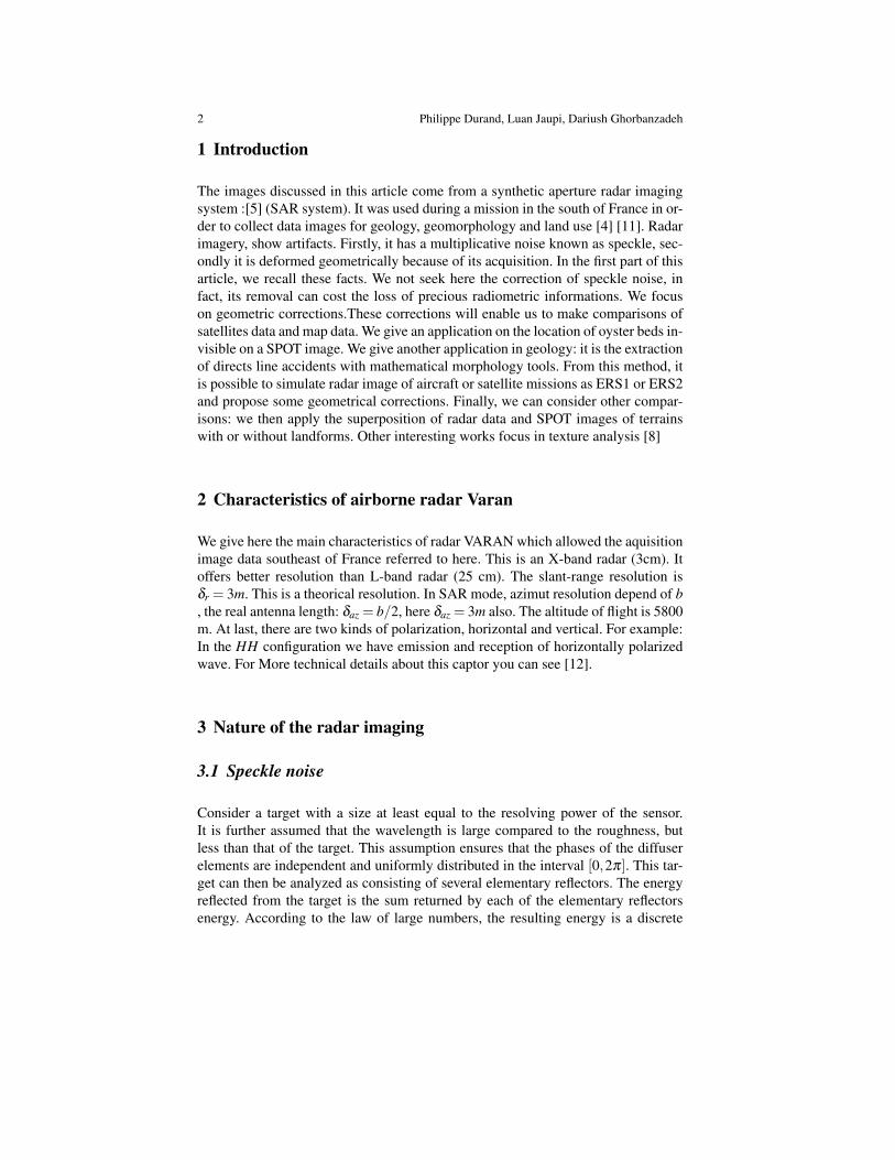
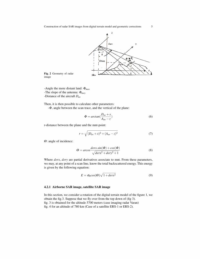
Fig. 1 Sainte Victoire mnt
Construction of radar SAR images from digital terrain model and geometric corrections 5
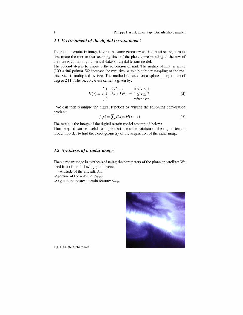
Fig. 2 Geometry of radarimage
-Angle the more distant land: Φmax-The slope of the antenna: Φmoy-Distance of the aircraft Dav
Then, it is then possible to calculate other parameters:-Φ , angle between the scan trace, and the vertical of the plane:
Φ = arctan(Dav + xAav− z
) (6)
r-distance between the plane and the mnt-point:
r =√(Dav + x)2 +(Aav− z)2 (7)
Θ : angle of incidence:
Θ = arcosderx.sin(Φ)+ cos(Φ)√
derx2 +dery2 +1(8)
Where derx, dery are partial derivatives associate to mnt. From these parameters,we may, at any point of a scan line, know the total backscattered energy. This energyis given by the following equation:
E = σ0cos(Θ)√
1+derx2 (9)
4.2.1 Airborne SAR image, satellite SAR image
In this section, we consider a rotation of the digital terrain model of the figure 1, weobtain the fig.3. Suppose that we fly over from the top down of (fig 3).fig. 3 is obtained for the altitude 5700 meters (case imaging radar Varan)fig. 4 for an altitude of 780 km (Case of a satellite ERS-1 or ERS-2).

6 Philippe Durand, Luan Jaupi, Dariush Ghorbanzadeh
Fig. 3 mnt rotated Fig. 4 Synthesis
We do not study here the correction of satellite images, because we do not havesatellite images of ERS-1 and ERS-2.
Fig. 5 Synthesized image atthe altitude of satellite ERS
If the resolution r is less than the mesh of the mnt, energy is recognized as theenergy returned by several pixels. During the synthesis, we share the energy receivedon these pixels. We will now make a readjustment, between the real scene and thesynthesized one from the digital terrain model and flight parameters of the aircraftpicture.
4.3 Readjustment of the real image on the synthesized image
From the digital terrain model (fig.1), we obtain the synthesis image fig.6 The syn-thetic image is the ideal image that would be obtained without speckle noise. Thereadjustment of the real image VARAN on this image synthesis should help rectifyerrors flight of the aircraft. The polynomial model of degree 2 is well suited for

Construction of radar SAR images from digital terrain model and geometric corrections 7
Fig. 6 Synthesized image Fig. 7 Real scene
this first correction. The average differences in x and y are approximately one pixel.A difference of one pixel from the exact point is a mandatory approximation. [6].Therefore, the readjustment can be considered very good.
Fig. 8 Readjustment of thereal image on the synthesized
However, the mnt resampled, the accuracy is 25 meters, for a more precise result,We would need to have more accurate digital terrain models.
4.4 Readjustment of the real image on mnt
The correspondence between the synthetic image and the digital terrain model isexact.
With the readjustment of the previous section, can be matched without new er-rors, the real scene and the digital terrain model. The method just described is inter-esting. However, we do not have mnt accurate enough to allow a systematic read-justment.

8 Philippe Durand, Luan Jaupi, Dariush Ghorbanzadeh
Fig. 9 Readjustment of thereal image on the mnt
5 Combinations between SPOT and VARAN data with orwithout relief.
The overlay data from multiple sensors, allows a better analysis in geology and ge-omorphology. It should provide a best understanding of the respective contributionsof the various sensors.
Fig. 10 Comparison Radar-Spot On ”Etangs de Tau”
5.1 Example 1
The first stage, Figure 10, represents the ponds Tau area), it shows a flat region with-out much distorsions.Only remain, those from the radar geometry in the SAR mode,but not reversals due to reliefs. In this case, the radar and SPOT geometries are simi-lar, in addition, the site has special features points that can be selected as landmarks:Cape border of cultivated plots, contour of the pond. A possible application could

Construction of radar SAR images from digital terrain model and geometric corrections 9
be followed in real time by satellite, drift oyster beds. Indeed, the image that wepresent shows the overlap between radar data and SPOT data. , The park oysters,submerged do not appear on the SPOT image, however, are clearly visible on theradar image.
5.2 Example 2
We also propose a methodology to reset the radar image on a SPOT image in reliefarea. At first, the distortions of the radar image is corrected by restoring the geome-try of the digital terrain model (see previous section). Then, the overlap between thecorrected radar image and SPOT Image is performed. This is a delicate operation,with the first readjustment errors, add those from the SPOT image (not exactly inthe geometry of the mnt. The acquisition of SPOT mnt on this region would allowus to solve this last source of errors. The relief features visible on the radar imageare superposed on the visible areas of SPOT imagery. (See Figure 11).
Fig. 11 Comparison Radar-Spot Sainte Victoire mountain
6 Application of mathematical morphology extraction directionsgeological accidents
The extraction of networks is a central topic of a great importance in remote sens-ing. From the radar scene acquired on the Massif de Bras (fig.12) ( Luc southernFrance) were extracted three directions of fractures affecting the Lias and partlyTriassic. They correspond to real families accidents. Two of these families wereknown. The radar scene confirmed their existence, in addition, the third direction(North 160) is to be highlighted. We can strengthen these directions, by manufac-turing of structuring elements, and the application of morphological operations in

10 Philippe Durand, Luan Jaupi, Dariush Ghorbanzadeh
each direction.[2],[3],[9]
Fig. 12 Direction of fractura-tion north 160
7 Conclusion
The geometric rectfication a radar image on the digital terrain model is the startingpoint that should be used to compare images with different geometries. Spot imag-ing is less sensitive to geomorphologic accidents . Instead, the radar image, cansolve this problem. On the other hand climatic conditions do not affect collect ofradar data. It is therefore essential to have more effective tools to compare the databetween them. We can only encourage research to efficient pretreatments. we needto develop tools that would help to improve the fusion of different satellite data, andbetter understand and use data from different sensor remote sensing.
References
1. Bernstein, R. Image geometry and rectification manual of remote sensing manual of remotesensing, American Society of Photogrametry, 21, 873-921 (1983)
2. Cuq,F., Durand, P., Hamidou, S., Simonin, A., Utilisation de filtres geostatistiques pourl”analyse de changement d’chelle partir d’images satellitaires, Photointerprtation Eska Paris,6, 33-38 (1990)
3. Durand, P., Hakdaoui, M., Chorowicz, J., Rudant, J.P., Simonin, A. Caracterisation des tex-tures urbaines sur image radar Varan par approche morphologique et statistique. Applicationa la ville du Luc, Int. J. Remote sensing, 15, no 5, 1065-1078, (1994)
4. Durand, P., Mekarnia, A, Chorowicz, J.,Tele-analyse geologique du radar aeroporte VARANsur la montagne Sainte Victoire, Photointerpretation Eska Paris, 27, no. 6, 1-10, (1988)
5. Durand, P.,Jaupi, L., et Ghorbanzadeh, D., Geometric Correction of Airborne Radar SARImage on a Digital Terrain Model, and Overlay with Satellite SPOT Data, Lecture Notesin Engineering and Computer Science: Proceedings of the World Congress on Engineering,WCE 2014, 2-4 July 2014, London, U.K.,pp 572-576.
6. Garinet, J.Y. Techniques de recalage d’images de tldetection et transparence, (Thesis,Toulouse, (1985)

Construction of radar SAR images from digital terrain model and geometric corrections 11
7. Goodman, J.W. Some fundamental properties of speckle, J. Opt. Soc. Am., 66, n◦ 11, 1145-1150, (1976)
8. LLoyd, C.D., Berberoglu, S., Curran, P.J. and Atkinson, P.M. A comparison of texture mea-sures for per-field classification of mediterranean land cover, Int. J. Remote sensing, 25, n 19,3943-3965, (2004)
9. Matheron, G. Elements pour une theorie des milieux poreux, Masson, (1967)10. Rudant, J.P. , Chorowicz, J., Durand, P. Problemes d’interpretation g’omorphologique
et modelisation geometrique d’images radar a partir d’un modele numerique de terrain,C.R.A.S,, Gauthier Villars, 306, n1, Paris, (1988)
11. Rudant, J.P., Cervelle, B., Chorowicz, J., Durand, P., Kamoun, P., Louhala S, Poli-dori,L., Riazanoff, S., Simonin, A., Tannous, I. Evaluation des donnees VARAN engeologie,geomorphologie sur le sud est de la France, Proc. of 4th International Colloquiumon Spectral Signatures of Objects in Remote Sensing (ESA) , (1988)
12. Vaillant, D. VARAN S: An airborne synthetic aperture radar for research in microwave remotesensing, Proc. EARSEL/ESA Symposium, 167-172 (1985)
View publication statsView publication stats