construction of pile foundation at galander … · construction of pile foundation at...
TRANSCRIPT
Construction of Pile Foundation at GALANDER-KANDIZAL Bridge in J&K
Mohammad Adil Dar 1, Prof (Dr) A.R. Dar
2 , Shazia Shafi
3 ,Jayalakshmi Raju
4
1PG Research Student, Department of Civil Engineering, SDDIET, Kurukshetra University , India
2Professor & Head Department of Civil Engineering, NIT, Srinagar, India
3PG Research Student, Department of Civil Engineering, NIT, Srinagar, India
4UG student, Department of Civil Engineering, MSRIT, Bangalore, India
ABSTRACT
A pile foundation is a civil engineering concept that is, at its most basic, a substructure that is
supported by piles. When it becomes impossible to provide the suitable surface foundation for a
structure ; the use of pile foundations becomes necessary, this situation arose from either the soil
condition or the order of bottom layers , the nature of the loads transferred to the soil or the
nature of the site and operational conditions.
The main components of the foundation are the pile cap and the piles .piles are long and slender
members which transfer the load to deeper soil or rock of high bearing capacity avoiding
shallow soil of low bearing capacity. The main types of materials used for piles are wood, steel
and concrete .Piles made from these materials are driven , drilled or jacked into the ground and
connected to pile caps. Depending upon type of soil ,pile materials and load transmitting
characteristic piles are classified accordingly.
Pile foundations have been used as load carrying and load transferring systems for many years .
In the early days Timber Piles were driven in to the ground by hand or holes were dug and
filled with sand and stones. Steel piles have been used since 1800 and concrete piles since about
1900.
The industrial revolution brought about important changes to pile driving system through the
invention of steam and diesel driven machines . More recently the growing need for housing and
construction has forced authorities and development agencies to exploit lands with poor soil
characteristics . This has led to the development and improved piles and pile driving systems.
Today there are many advanced techniques of pile installation.
INTRODUCTION
Our project entitled ‘ Pile Foundation’ of GallenderKandizalBidge AtPampore @ ch 277 + 070
which is being constructed by RAMKY INFRASTRUCTURE LTD.
This project is actually a highway expressway project from Jammu To Srinagar under the
authority of NHAI (National Highways Authority Of India). This project is being constructed by
Ramky Infrastructure Ltd on the basis of B.O.T(Built Operate Transfer) . The expressway
reduces the distance between Jammu and Srinagar by 75 km’s. The expressway consists of a
number of culverts , minor bridges ,Tunnels and a major bridge at Gallender-Kandizal(Pampore).
90
International Journal of Engineering Research & Technology (IJERT)
Vol. 2 Issue 10, October - 2013
IJERT
IJERT
ISSN: 2278-0181
www.ijert.orgIJERTV2IS100070
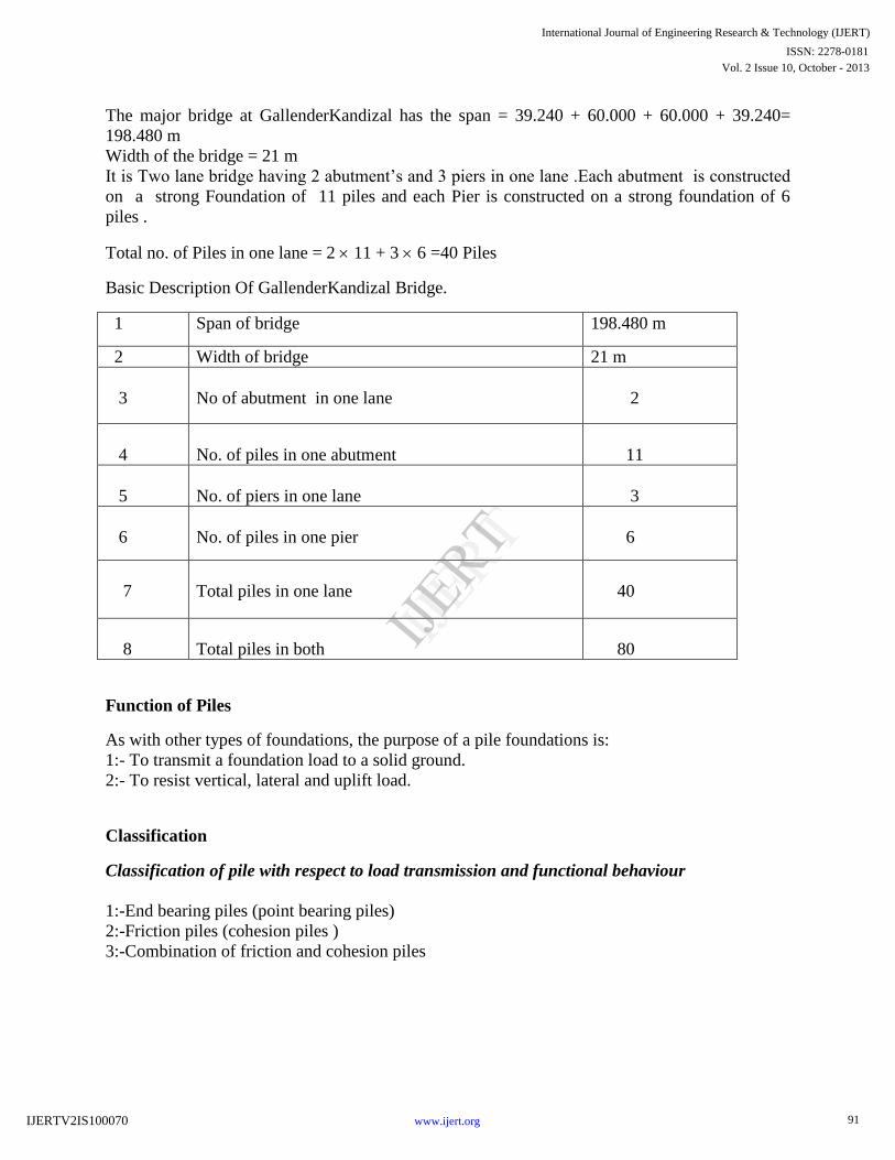
The major bridge at GallenderKandizal has the span = 39.240 + 60.000 + 60.000 + 39.240=
198.480 m
Width of the bridge = 21 m
It is Two lane bridge having 2 abutment’s and 3 piers in one lane .Each abutment is constructed
on a strong Foundation of 11 piles and each Pier is constructed on a strong foundation of 6
piles .
Total no. of Piles in one lane = 2 11 + 3 6 =40 Piles
Basic Description Of GallenderKandizal Bridge.
1 Span of bridge 198.480 m
2 Width of bridge 21 m
3
No of abutment in one lane
2
4
No. of piles in one abutment
11
5
No. of piers in one lane
3
6
No. of piles in one pier
6
7
Total piles in one lane
40
8
Total piles in both
80
Function of Piles
As with other types of foundations, the purpose of a pile foundations is:
1:- To transmit a foundation load to a solid ground.
2:- To resist vertical, lateral and uplift load.
Classification
Classification of pile with respect to load transmission and functional behaviour
1:-End bearing piles (point bearing piles)
2:-Friction piles (cohesion piles )
3:-Combination of friction and cohesion piles
91
International Journal of Engineering Research & Technology (IJERT)
Vol. 2 Issue 10, October - 2013
IJERT
IJERT
ISSN: 2278-0181
www.ijert.orgIJERTV2IS100070
Classification of pile with respect to type of material
• Timber
• Concrete
• Steel
•Composite piles
ENGINEERING CONSIDERATIONS PERTAINING TO CONSTRUCTION
1 General
2 Construction Practices and Equipment
3 Driving
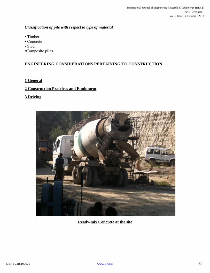
Ready-mix Concrete at the site
92
International Journal of Engineering Research & Technology (IJERT)
Vol. 2 Issue 10, October - 2013
IJERT
IJERT
ISSN: 2278-0181
www.ijert.orgIJERTV2IS100070
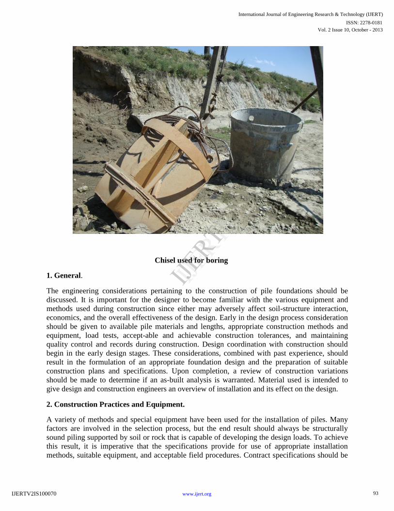
Chisel used for boring
1. General.
The engineering considerations pertaining to the construction of pile foundations should be
discussed. It is important for the designer to become familiar with the various equipment and
methods used during construction since either may adversely affect soil-structure interaction,
economics, and the overall effectiveness of the design. Early in the design process consideration
should be given to available pile materials and lengths, appropriate construction methods and
equipment, load tests, accept-able and achievable construction tolerances, and maintaining
quality control and records during construction. Design coordination with construction should
begin in the early design stages. These considerations, combined with past experience, should
result in the formulation of an appropriate foundation design and the preparation of suitable
construction plans and specifications. Upon completion, a review of construction variations
should be made to determine if an as-built analysis is warranted. Material used is intended to
give design and construction engineers an overview of installation and its effect on the design.
2. Construction Practices and Equipment.
A variety of methods and special equipment have been used for the installation of piles. Many
factors are involved in the selection process, but the end result should always be structurally
sound piling supported by soil or rock that is capable of developing the design loads. To achieve
this result, it is imperative that the specifications provide for use of appropriate installation
methods, suitable equipment, and acceptable field procedures. Contract specifications should be
93
International Journal of Engineering Research & Technology (IJERT)
Vol. 2 Issue 10, October - 2013
IJERT
IJERT
ISSN: 2278-0181
www.ijert.orgIJERTV2IS100070
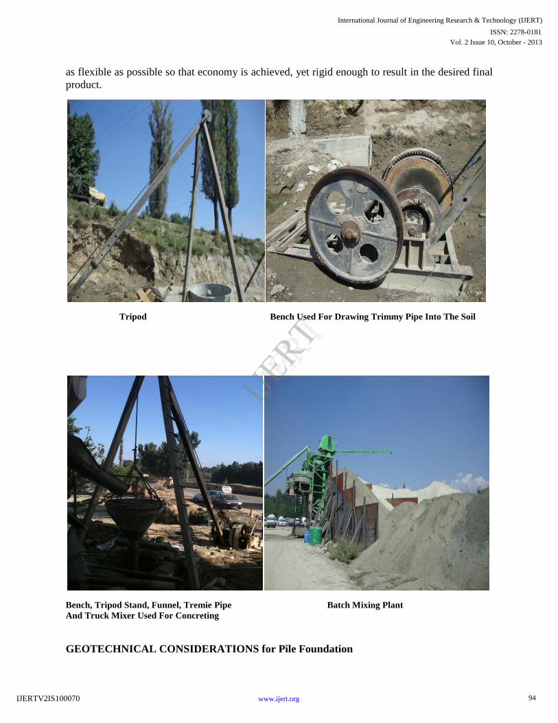
as flexible as possible so that economy is achieved, yet rigid enough to result in the desired final
product.
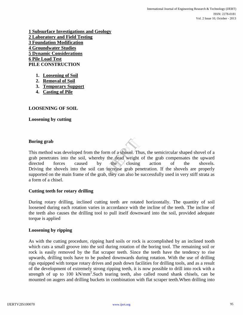
Tripod Bench Used For Drawing Trimmy Pipe Into The Soil
Bench, Tripod Stand, Funnel, Tremie Pipe Batch Mixing Plant And Truck Mixer Used For Concreting
GEOTECHNICAL CONSIDERATIONS for Pile Foundation
94
International Journal of Engineering Research & Technology (IJERT)
Vol. 2 Issue 10, October - 2013
IJERT
IJERT
ISSN: 2278-0181
www.ijert.orgIJERTV2IS100070
1 Subsurface Investigations and Geology
2 Laboratory and Field Testing
3 Foundation Modification
4 Groundwater Studies
5 Dynamic Considerations
6 Pile Load Test
PILE CONSTRUCTION
1. Loosening of Soil
2. Removal of Soil
3. Temporary Support
4. Casting of Pile
LOOSENING OF SOIL
Loosening by cutting
Boring grab
This method was developed from the form of a shovel. Thus, the semicircular shaped shovel of a
grab penetrates into the soil, whereby the dead weight of the grab compensates the upward
directed forces caused by the closing action of the shovels.
Driving the shovels into the soil can increase grab penetration. If the shovels are properly
supported on the main frame of the grab, they can also be successfully used in very stiff strata as
a form of a chisel.
Cutting teeth for rotary drilling
During rotary drilling, inclined cutting teeth are rotated horizontally. The quantity of soil
loosened during each rotation varies in accordance with the incline of the teeth. The incline of
the teeth also causes the drilling tool to pull itself downward into the soil, provided adequate
torque is applied
Loosening by ripping
As with the cutting procedure, ripping hard soils or rock is accomplished by an inclined tooth
which cuts a small groove into the soil during rotation of the boring tool. The remaining soil or
rock is easily removed by the flat scraper teeth. Since the teeth have the tendency to rise
upwards, drilling tools have to be pushed downwards during rotation. With the use of drilling
rigs equipped with torque rotary drives and push down facilities for drilling tools, and as a result
of the development of extremely strong ripping teeth, it is now possible to drill into rock with a
strength of up to 100 kN/mm2.Such tearing teeth, also called round shank chisels, can be
mounted on augers and drilling buckets in combination with flat scraper teeth.When drilling into
95
International Journal of Engineering Research & Technology (IJERT)
Vol. 2 Issue 10, October - 2013
IJERT
IJERT
ISSN: 2278-0181
www.ijert.orgIJERTV2IS100070
very hard soils, it is more efficient to first cut an outer annulus. Stress release can then occur in
the remaining core, enabling it to be easily broken up and removed.
CASTING OF PILE
Concrete mixes for bored piles
The integrity and high quality of the pile shaft is of paramount importance. Special concrete
mixes and methods for casting in-situ have been developed for bored piles, as opposed to the
high-strength concrete, necessary for precast piles or structural work above ground. This has led
to the adoption of rather sophisticated, highly workable mixes, using different types of additives
(plastizisers and retarders) flows between the reinforcing bars with ease, and into the interstices
of the soil. For this purpose, a high-slump, self-compacting mix is called for. A minimum cement
content of 300 kg/m3 is generally used, increasing to 400 kg/m
3 at slumps greater than 150 mm,
with a corresponding increase in fine aggregate content to maintain the cohesion of the mix.
Three concrete mixes, recommended by the Federation of Piling Specialists, are given below.
Piling
mix
Typical slump
(mm)
Conditions of use
A 125 Poured into water-free unlined bore. Widely spaced
reinforcement leaving ample room for free movement of
the concrete between bars.
B 150 Where reinforcement is not spaced widely enough to
give free movement of concrete between bars. Where
cut-off level of concrete is within casing. Where pile
diameter is < 600 mm.
C >175 Where concrete is to be placed by tremie under water or
bentonite in slurry.
96
International Journal of Engineering Research & Technology (IJERT)
Vol. 2 Issue 10, October - 2013
IJERT
IJERT
ISSN: 2278-0181
www.ijert.orgIJERTV2IS100070
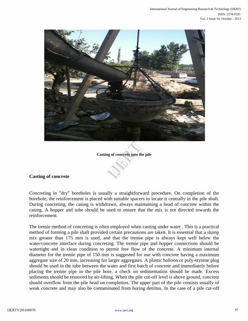
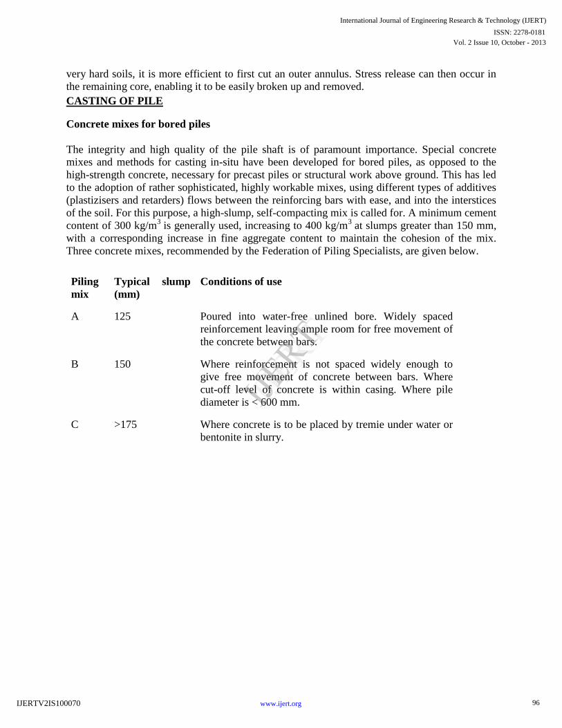
Casting of concrete into the pile
Casting of concrete
Concreting in "dry" boreholes is usually a straightforward procedure. On completion of the
borehole, the reinforcement is placed with suitable spacers to locate it centrally in the pile shaft.
During concreting, the casing is withdrawn, always maintaining a head of concrete within the
casing. A hopper and tube should be used to ensure that the mix is not directed towards the
reinforcement.
The tremie method of concreting is often employed when casting under water . This is a practical
method of forming a pile shaft provided certain precautions are taken. It is essential that a slump
mix greater than 175 mm is used, and that the tremie pipe is always kept well below the
water/concrete interface during concreting. The tremie pipe and hopper connections should be
watertight and in clean condition to permit free flow of the concrete. A minimum internal
diameter for the tremie pipe of 150 mm is suggested for use with concrete having a maximum
aggregate size of 20 mm, increasing for larger aggregates. A plastic balloon or poly-styrene plug
should be used in the tube between the water and first batch of concrete and immediately before
placing the tremie pipe in the pile bore, a check on sedimentation should be made. Excess
sediments should be removed by air-lifting. When the pile cut-off level is above ground, concrete
should overflow from the pile head on completion. The upper part of the pile consists usually of
weak concrete and may also be contaminated from boring detritus. In the case of a pile cut-off
97
International Journal of Engineering Research & Technology (IJERT)
Vol. 2 Issue 10, October - 2013
IJERT
IJERT
ISSN: 2278-0181
www.ijert.orgIJERTV2IS100070
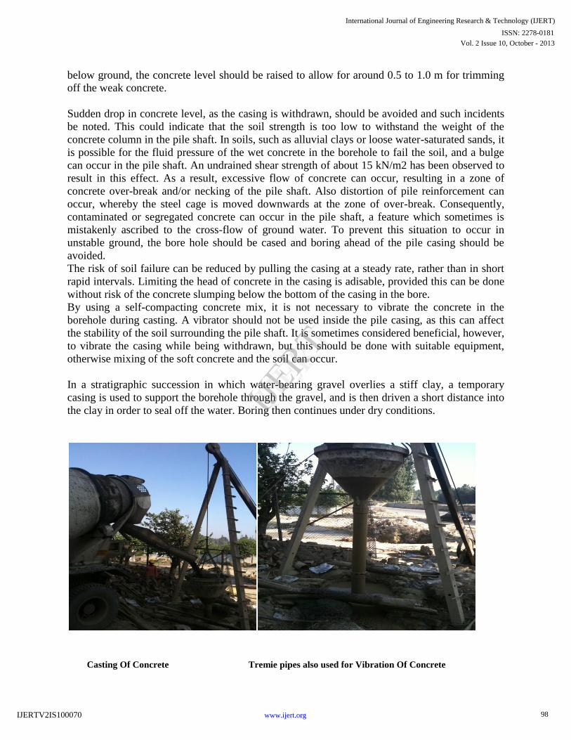
below ground, the concrete level should be raised to allow for around 0.5 to 1.0 m for trimming
off the weak concrete.
Sudden drop in concrete level, as the casing is withdrawn, should be avoided and such incidents
be noted. This could indicate that the soil strength is too low to withstand the weight of the
concrete column in the pile shaft. In soils, such as alluvial clays or loose water-saturated sands, it
is possible for the fluid pressure of the wet concrete in the borehole to fail the soil, and a bulge
can occur in the pile shaft. An undrained shear strength of about 15 kN/m2 has been observed to
result in this effect. As a result, excessive flow of concrete can occur, resulting in a zone of
concrete over-break and/or necking of the pile shaft. Also distortion of pile reinforcement can
occur, whereby the steel cage is moved downwards at the zone of over-break. Consequently,
contaminated or segregated concrete can occur in the pile shaft, a feature which sometimes is
mistakenly ascribed to the cross-flow of ground water. To prevent this situation to occur in
unstable ground, the bore hole should be cased and boring ahead of the pile casing should be
avoided.
The risk of soil failure can be reduced by pulling the casing at a steady rate, rather than in short
rapid intervals. Limiting the head of concrete in the casing is adisable, provided this can be done
without risk of the concrete slumping below the bottom of the casing in the bore.
By using a self-compacting concrete mix, it is not necessary to vibrate the concrete in the
borehole during casting. A vibrator should not be used inside the pile casing, as this can affect
the stability of the soil surrounding the pile shaft. It is sometimes considered beneficial, however,
to vibrate the casing while being withdrawn, but this should be done with suitable equipment,
otherwise mixing of the soft concrete and the soil can occur.
In a stratigraphic succession in which water-bearing gravel overlies a stiff clay, a temporary
casing is used to support the borehole through the gravel, and is then driven a short distance into
the clay in order to seal off the water. Boring then continues under dry conditions.
Casting Of Concrete Tremie pipes also used for Vibration Of Concrete
98
International Journal of Engineering Research & Technology (IJERT)
Vol. 2 Issue 10, October - 2013
IJERT
IJERT
ISSN: 2278-0181
www.ijert.orgIJERTV2IS100070
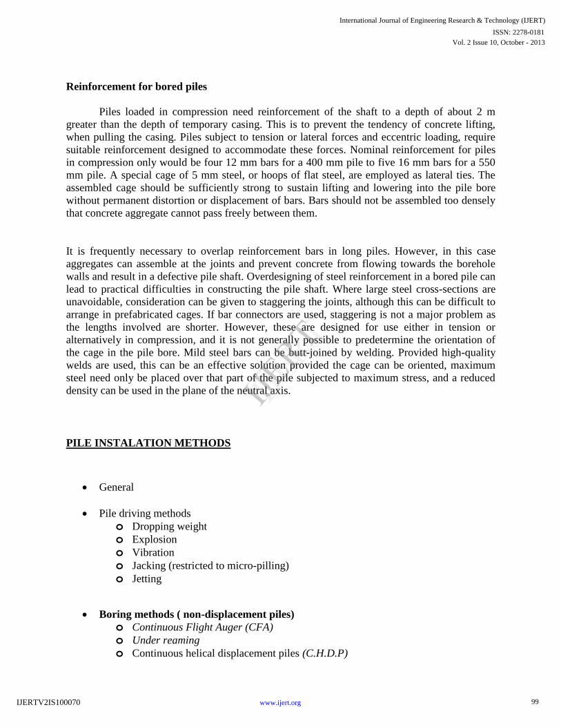
Reinforcement for bored piles
Piles loaded in compression need reinforcement of the shaft to a depth of about 2 m
greater than the depth of temporary casing. This is to prevent the tendency of concrete lifting,
when pulling the casing. Piles subject to tension or lateral forces and eccentric loading, require
suitable reinforcement designed to accommodate these forces. Nominal reinforcement for piles
in compression only would be four 12 mm bars for a 400 mm pile to five 16 mm bars for a 550
mm pile. A special cage of 5 mm steel, or hoops of flat steel, are employed as lateral ties. The
assembled cage should be sufficiently strong to sustain lifting and lowering into the pile bore
without permanent distortion or displacement of bars. Bars should not be assembled too densely
that concrete aggregate cannot pass freely between them.
It is frequently necessary to overlap reinforcement bars in long piles. However, in this case
aggregates can assemble at the joints and prevent concrete from flowing towards the borehole
walls and result in a defective pile shaft. Overdesigning of steel reinforcement in a bored pile can
lead to practical difficulties in constructing the pile shaft. Where large steel cross-sections are
unavoidable, consideration can be given to staggering the joints, although this can be difficult to
arrange in prefabricated cages. If bar connectors are used, staggering is not a major problem as
the lengths involved are shorter. However, these are designed for use either in tension or
alternatively in compression, and it is not generally possible to predetermine the orientation of
the cage in the pile bore. Mild steel bars can be butt-joined by welding. Provided high-quality
welds are used, this can be an effective solution provided the cage can be oriented, maximum
steel need only be placed over that part of the pile subjected to maximum stress, and a reduced
density can be used in the plane of the neutral axis.
PILE INSTALATION METHODS
General
Pile driving methods
o Dropping weight
o Explosion
o Vibration
o Jacking (restricted to micro-pilling)
o Jetting
Boring methods ( non-displacement piles)
o Continuous Flight Auger (CFA)
o Under reaming
o Continuous helical displacement piles (C.H.D.P)
99
International Journal of Engineering Research & Technology (IJERT)
Vol. 2 Issue 10, October - 2013
IJERT
IJERT
ISSN: 2278-0181
www.ijert.orgIJERTV2IS100070
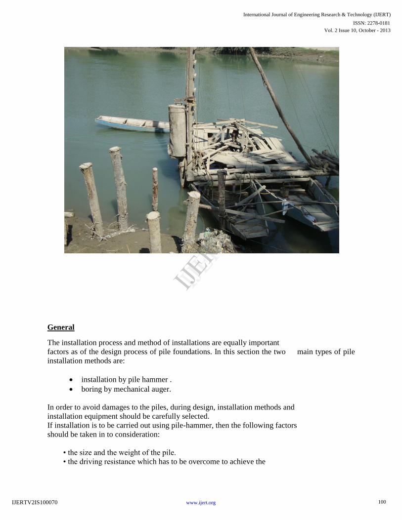
General
The installation process and method of installations are equally important
factors as of the design process of pile foundations. In this section the two main types of pile
installation methods are:
installation by pile hammer .
boring by mechanical auger.
In order to avoid damages to the piles, during design, installation methods and
installation equipment should be carefully selected.
If installation is to be carried out using pile-hammer, then the following factors
should be taken in to consideration:
• the size and the weight of the pile.
• the driving resistance which has to be overcome to achieve the
100
International Journal of Engineering Research & Technology (IJERT)
Vol. 2 Issue 10, October - 2013
IJERT
IJERT
ISSN: 2278-0181
www.ijert.orgIJERTV2IS100070
design penetration.
• the available space and head room on the site.
• the availability of cranes and
• the noise restrictions which may be in force in the locality.
Pile driving methods (displacement piles)
Dropping weight
Drop hammers: A hammer with approximately the weight of the pile is raised a suitable height
in a guide and released to strike the pile head. This is a simple form of hammer used in
conjunction with light frames and test piling, where it may be uneconomical to bring a steam
boiler or compressor on to a site to drive very limited number of piles.
There are two main types of drop hammers:
• Single-acting steam or compressed-air hammers
• Double-acting pile hammers
1. Single-acting steam or compressed-air comprises of a massive weight in the form of a
cylinder (see fig). Steam or compressed air admitted to the cylinder raises it up the fixed piston
rod. At the top of the stroke, or at a lesser height which can be controlled by the operator, the
steam is cut off and the cylinder falls freely on the pile helmet.
2. Double-acting pile hammers can be driven by steam or compressed air.
A pilling frame is not required with this type of hammer which can be attached to the top of the
pile by leg-guides, the pile being guided by a timber framework. When used with a pile frame,
back guides are bolted to the hammer to engage with leaders, and only short leg-guides are
used to prevent the hammer from moving relatively to the top of the pile.
Double-acting hammers are used mainly for sheet pile driving.
References
1. Massachusetts Turnpike Authority (2000), Project Summary, http://www.bigdig.com/thtml/ summary.htm.
2. Massachusetts Turnpike Authority (2000), Project Contract Lists, http://www.bigdig.com/ thtml/contlist.htm.
3. Massachusetts Turnpike Authority (2000), Maps and Plans, http://www.bigdig.com/thtml/ maps01.htm.
4. GZA GeoEnvironmental, Inc. (1991), Central Artery (I-93)/Tunnel (I-90) Project, Geotechnical Data Report,
South Bay Interchange, Design Sections D009B/D009C, Boston, MA.
5. GZA GeoEnvironmental, Inc. (1992), Central Artery (I-93)/Tunnel (I-90) Project, Geotechnical Data Report,
South Bay Interchange, Design Section D009A, Boston, MA.
6. Haley and Aldrich, Inc. (1991), Final Geotechnical Data Report, Central Artery (I-;93)/Tunnel (I-90) Project,
Design Sections D007C and D007D (C07D2), Boston, MA.
7. Haley and Aldrich, Inc. (1996), Final Geotechnical Report, Central Artery (I-93)/Tunnel (I-;90) Project,
Design Section D008A, Boston, MA.
101
International Journal of Engineering Research & Technology (IJERT)
Vol. 2 Issue 10, October - 2013
IJERT
IJERT
ISSN: 2278-0181
www.ijert.orgIJERTV2IS100070
8. Maguire Group, Inc., and Frederic R. Harris, Inc. (1995), Final Report on Soil Stabilization and Testing
Program, Central Artery (I-93)/Tunnel (I-90) Project, D009A, Boston, MA.
9. Maguire Group, Inc., and Frederic R. Harris, Inc. (1995), Supplemental Geotechnical Data Report, Central
Artery (I-93)/Tunnel (I-90) Project, Design Section D009A, Boston, MA.
10. Stone and Webster, Inc. (1996), Final Geotechnical Data Report, Central Artery (I-;93)/Tunnel (I-90) Project,
Design Section D019B, I-93 Viaducts and Ramps North of Charles River, Boston, MA.
11. Barosh, P.J.; Kaye, C.A.; and Woodhouse, D. (1989), "Geology of the Boston Basin and Vicinity." Civil
Engineering Practice: Journal of the Boston Society of Civil Engineers, 4(1), 39-52.
12. McGinn, A.J., and O'Rourke, T.D. (2003), Performance of Deep Mixing Methods at Fort Point Channel,
Cornell University, Ithaca, NY.
13. Commonwealth of Massachusetts (1997), The Massachusetts State Building Code, Users Guide to 780
CMR (6th Edition), William F. Galvin, Boston, MA.
102
International Journal of Engineering Research & Technology (IJERT)
Vol. 2 Issue 10, October - 2013
IJERT
IJERT
ISSN: 2278-0181
www.ijert.orgIJERTV2IS100070