constellation program electrical ground support … program electrical ground support equipment...
TRANSCRIPT

NASA USRP - Internship Final Report
Constellation Program Electrical Ground Support Equipment Research and Development
Keegan S. McCoy' The Pennsylvania State University, Universiry Park. PII , 16802
At the Kennedy Space Center, I engaged in the research and development of electrical ground support equipment for NASA's Constellation Program. Timing characteristics playa crucial role in ground support communications. Latency and jitter are two problems that must be understood so that communications are timely and consistent within the Kennedy Ground Control System (KGCS). I conducted latency and jitter tests using Alien-Bradley programmable logic controllers (PLCs) so that these two intrinsic network properties can be reduced. Time stamping and clock synchronization also play significant roles in launch processing and operations. Using RSLogix 5000 project files and Wireshark network protocol analyzing software, I verified master/slave PLC Ethernet module clock synchronization, master/s lave IEEE 1588 communications, and time stamping capabilities. All of the timing and synchronization test results are useful in assessing the current KGCS operational level and determining improvements for the future.
I. Introduction
This spring semester. I interned in the Electrical Design Branch at the Kennedy Space Center (KSC) through the Undergraduate Student Research Program (USRP). Working in the Controls Lab of the Engineering Development Lab, my individual proj ect was focused on the research and development of e lectrical ground support equipment for NASA's Constellation Program. Particularly important for ground support equipment are timing characteristics. The tests that I performed measured the timeliness and consistency of programmable logic contro ller (PLC) communications. ve rified test procedures, and demonstrated the abi li ty to time stamp data packets and synchronize the PLC network . All of these tasks are crucial to the successful operation o f ground support equipment that aids in launch processing and operat ions.
My first task was to understand the role of PLCs in command and control applications, s ince KSC employs a programmable contro l system to operate the thousands of valves, switches, regulalOrs, and sensors on the launch tower necessary for lau nch operations.
Programmable control systems were first developed as an alternative to relay systems. Programmable contro l systems hold many advantages over electromechanical relays, inc luding enab ling eas ier access for maintenance personnel , as well as only requiring edits to a project file for system changes rather than rewiring. Furthermore, programmable control system so lid-state parts are capable of surviving harsh, industrial environments, their component lifetimes are long, and the components are modular and easy to replace. )
Information in a programmable control system flows in the fo llowing order:
~ C ProcesslMachine/Device ~ ~ Monitor Control
I Control ler I Evaluate
Figure I. Information now in a programmable control system.'
I. The system monitors input information from a process, machine, or device (e.g., a sensor).
J Student, Department of Electrical Engineering and Department of Astronomy and Astrophys ics, The Pennsylvania State University. Student Member AIAA.
https://ntrs.nasa.gov/search.jsp?R=20110001576 2018-06-27T01:52:20+00:00Z

NASA USRP - Internship Fi nal Repon
2. A cont ro ller evaluates the input informat ion based on a given set of ru les and then generates output information (e.g., shut a valve if the sensor detects a certain pressure).
3. The output informat ion is used to control the process, machine, or device (e.g. , the valve closes).
II. Programmable Control System Components
All programmable contro l systems consist of four main components: • Programming system • Communications network • Control ler • I/O (input/output) system
A. Controller A contro ller is a so lid-state device with user-programmable memory and a central processor, serving as the brain
of a program mable cont rol system. I Cont ro llers perform the fo llowi ng functions: • 110 control • Logic • Timing • Report generation • Communications • Data manipulat ion
For the Constellation Program's KGCS, NASA is using Allen-Bradley Cont ro lLogix controllers produced by Rockwell Automation.
B. Input/Output (I/O) System An I/O system consists of the followi ng components: l
• I/O modules, wh ich are pan of the programmable contro l system • [/0 devices, which are part of the process/mach ine
An 110 system sends input and output information between a controller and a process/machine. An input device, such as a pressure transducer on the launch pad, supplies signals th rough an input module to a controller. An output device (e.g. , a valve, switch, regulator, sensor, etc.) is actuated or energized by a controller through an output module.
NASA is uti li zing a wide array of Allen.Bradley 110 modules, ranging from analog and digi tal mod ules used to collect and send information. to motion control modules capable of controll ing the movement of end items. These 110 modu les are modular, allowing for easy addi tion or removal from the PLC chass is.
C. Programming System Composed of a programming device (e.g., personal computer, laptop) and software, a programming system is
used to program and monitor the operation of a contro ller. ' RSLogix 5000, a software program developed by Rockwell Automation, allows NASA to write code in project
fil es to control the vast PLC network . The program has a flexibl e instruction set, enabling users to write code in ladder logic, structured text, fun ction block diagram s, or sequential function charts, depending on the best fit for the specific app lication.
D. Communications Network A communications network is the physical connection between a series of components or devices. This
connection is used to transfer data between the components, such as a computer in the Launch Control Center (LCC) and a controller, using a cable system. I
The KGCS em ploys a fe w different communications networks. The Control Net network is a real-time control network that provides high-speed transport of both time-critical 110 and messaging data, including uploading and downloading of programming and con figuration data. The ControlNet network is highly determini stic and repeatable. remaining unaffected as devices are connected or disconnected from the network. This robust quality resu lts in dependab le, synchroni zed, and coordinated real-time performance. ControlNet connects remote 110 (RIO) modules contained in separate chassis with the main contro ller contained in a local chassis , allowing for scheduling of all module communications.
2
NASA US RP - Internship Final Repon
Several timing va lues play significant roles in Contro lNet com munications. The Req uested Packet Interval (RPI) speci fie s the period at whi ch an 1/0 module updates to the backplane. Typically, RPls fall in the mi llisecond range, from 0.2 ms to 750 ms. The RPI reserves a slot in the stream of data fl owing across the ControlNet network, as all IJO modules have individual RPls. Although the timing of the slot may not coincide wi th the exact value of the RPI , the contro l system guarantees that the data transfers at least as often as the RPI.
Analog input modules have a real-time sampling (RTS ) va lue that speci fi es the module 's sampling interval of the particular data being collected by the connected 110 device. The RTS value must always be greater than or equal to the RPI. If the module's RTS is lower than its RPI, samples will be lost, since the backplane is not being updated quickly enough to keep pace with the sample rate.
The Network Update Time (NUT) detennines the time interval at which data from the 110 modules is collected and sent to the controller th rough the backplane. The NUT is set using RSNetworx, an add-on program to RSLogix 5000 that allows network scheduling and bandwidth calculations. In general, all module RPl s must be greater than or equal to the NUT or in formation wi ll be lost from the individual module updates. The ideal choice is often to set the modul e RPls equal to the NUT, which not only prevents losing in format ion, but also redundant values.
Another communications network supported by the Allen-Brad ley PLCs is EtherNet/IP, wh ich is carried on an RJ-45 cable. The main fun ctions of the EtherNetilP network are to send infomlation back and fonh from the LCC Gateway and to enable master/slave clock synchron ization. The EtherNet/IP network is unscheduled, allowing for information to be sent or received as needed.
III. Kennedy Ground Control System
A. Operational Description The Kennedy Ground Control System (KGCS) is one of the key components of the Constellation Program's
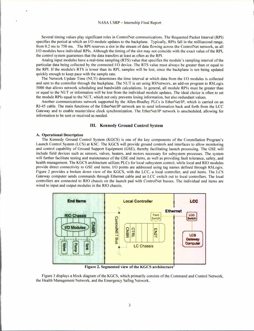
Launch Control System (LCS ) at KSC. The KGCS wi ll provide ground controls and interfaces to allow monitoring and cont ro l capability of Ground Suppon Equipment (GSE), thereby facilitating lau nch processi ng. The GSE will include fi eld devices such as sensors, valves, heaters, and motors necessary for subsystem processes. The system wi ll further faci litate testing and mai ntenance of the GSE end items, as we ll as providing fau lt tolerance, safety, and health management. The KGCS archi tecture utilizes PLCs for local subsystem control . while local and RIO modules provide direct connectivity to GSE end items. 110 points are addressed using lag names defined through RSLogix. Figure 2 provides a broken down view of the KGCS, with the LCC, a local controller, and end items. The LCS Gateway computer sends commands through Ethernet cable and an LCC switch out to local controllers. The local controllers are connected to RIO chassis on the launch pad with ControlNet busses. The indi vid ual end items are wired to input and output modules in the RIO chassis.
End Items
RIO r II 0
~IO Modules) Z I I I !II
~,:l: .... ,;:l: ..•.• ,:±:. , :r ~ ;j i ~ 3 ~ ' .." ' -!=.-... ~.-. - .• '=-.. '
Local Controller
[ Fi.~ 1 SwitCh
LC Chassis
m z ~
Ethernet
Figure 2. Segmented view of the KGCS archltecture2
LCC
(~l I
~C5
GalBway Computer
Figure 3 displays a block diagram of the KGCS, which primarily consists of the Command and Control Network, the Health Management Network, and the Emergency Sating Network.
3
l

NASA US RP - Internship Final Report
Command and Control Network
EthernetiP
Health Management Network
Emergency
B. Command and Control Network
Control Net
PadlML
Figure 3. KGCS Block Diagram'
The KGCS Command and Control Network (CCN) provides the real-time monitoring and control of GSE. It provides the direct interface to the end items fo r subsystems and faci litates local and remote monitoring and contro l by the users through a local human-machi ne interface (HM I) or through the LCS user interface. The RIO performs the signal conditioning and digiti zation of signals, which are then sent to the local controller for processing and further transmission to the LCS Gateway. The local contro ll er also has the capabil ity to perform closed-loop control and reactive-control logic for time-critical responses to the end items.) The CCN provides the critical data from field instrumentation and control devices to other LCS components, slich as app li cation servers and record and playback recorders. These data contain critical information that is used to measure the subsystem process health and control subsystem process.
C. Health Management Network The KGCS will utilize a Health Management Network (HMN) that provides system monitoring and supervisory
control fo r subsystem maintenance, troubleshooting, and configuration. This wi ll provide health status of the PLCs and other KGCS components, such as sensors and transducers, to the GSE engineers who will be responsible in maintaining the fie ld hardware. The HMN will also assist engineers in the initial verification of the GSE, troubleshooting, and maintenance. It contributes to a more efficient process without requiring the LCS control room to be running when performing a quick instrumentat ion snapshot. The HMN will interface with historical servers and provide automatic reporting and trending of process data. The HMN will also interface to the LCS System Management Console (SMC) for configurati on management of PLC application software and IT security. Software that wi ll be archived and wi ll follow configuration management incl udes app lication programs, PanelView software, and PLC firmware . The HMN receives appl ication programs and PLC firmware from the SMC to update the PLCs on the field.
D. Emergency Sa fin g Network The Emergency Safi ng Network (EMSF) will provide safing capabilities of end items in the event of an
emergency independent from the Command and Control Network. EMSF seq uences are manually initiated by the system engineers on the console fro m a dedicated emergency safing panel. The EMSF shall override all other contro ls and exert final control of the equipment when act ivated. No other systems shall be capable of overriding the EM SF. The EM SF employs red undancy fo r PLC devices, RIO, instrumentation whenever feasible, communications, and power distribut ion.3 EMSF will be independent of the Command and Control Network and is an integral part of the KGCS.
4

---------------------------------
NASA US RP - Internsh ip Final Report
IV. KGCS Testing
A. Latency and Jitter My first hands-on task involved cond ucting tests measuring the latency and jitter of PLC communicat ions. In
general , latency is the amount of time it takes for a data packet to travel end-Io-end through a network.4 Several fac tors may contribute to a network 's latency, includ ing propagation, serializatio n, queue, and processing delays. Propagation delay is inherent in any network due to the finite nature of the speed of light in the transmiss ion of electri cal or optical signals. For example, the LCC is located about 3.4 miles (5.47 km) away from Launch Complex 39, where the Constellation Program 's Ares I and V rockets will launch. Therefore, not taking into account propagation delay caused by the transmitting material itself, there will be an intrins ic speed of light delay each way of around 18 .25 )..ls. Serialization delay refers to the time it takes a network device to encode and transmit a data packet, which is a function of packet size and transmiss ion rate. Queuing delay measures the time that a data packet must wait in a buffer before it is sent. 4 This may become significant if data packets are sent to the transmitting device at a higher rate than the device is capable of transmitting packets. Process ing delay is the time that it takes to hand le data packets wit hi n a network node (e.g., a contro ller), which is dependent upon the speed of the device and the congestion in the network. In the past, processing delay has often been neglected; however, in some systems the process ing de lay can be qu ite significant, especially where routers are performing complex encryption algorithms and examining or modify ing packet content.
Due to varyi ng internal and external factors, latency may change in a network with time. Jitter is a measure of the resulting variat ion in latency. Jitter may be caused by a change in data packet s ize, variance in queue delay due to receiving packets from multiple sources, o r data packets trave ling over d ifferent paths to arri ve at the same destination.
For the purposes of the KGCS, latency measures the delay between when a command is sent from the LCC to the time at which the end item (valve, switch, etc.) physically reacts. Jitter in the KGCS is caused by a variety of factors, including individual module RTS and RP I va lues, as well as the NUT.
I perfonned simple measurements of PLC latency and jitter in the Controls Lab, not taking into account the fu ll propagation delay from the LCC to Launch Complex 39. To carry out the tests, I set up two chass is. The upper, local chassis contained a Logix 5563 contro ller, an EN2T Ethernet module, and a ControlNet module. The lower, remote chass is consisted of an EN2T Ethernet module, a Contro lNet module, an IB 16 discrete input module, and an OB8 discrete output module. The input module was connected to a functi on generato r, which was meant to imitate an incoming signal from an end item, while the output module was hooked up to an osci lloscope to view the PLC's input and output signals. By measuring the time delay of the input and output signals over a number of samples, latency and jitter could be measured for each test. Figure 4 shows the test configuration with the local chassis, remote chassis, fu nction generator, osci lloscope, and power rail.
For each test run , I set the function generator to input a I Hz, 20-V pp square wave (O-V DC offset), which was viewed on Channel I of the osci lloscope. The resulting output of each test was observed on Channel 2 of the oscilloscope as a 28-Vpp square wave (14-V DC offset), due to the 28 vo lts supplied by the power supply. Figure 5 shows the RSLogix code used to implement the test, with the code consisti ng of a single rung of ladder logic that reads the function generator input and sends it unchanged through an output module to be disp layed on the osci lloscope . For Test # I, the ControlNet RPI , IB I6 RPI , OB8 RP I, and NUT were all set to 10 ms. The result of Test # I is shown below in Fig. 6 (Channel I in ye llow, Channe l 2 in pink) .
Figure 4. Latency and jitter test configuration.
5

NASA USRP - Internship Final Report
....... _ .. - .... _- ,-- -I r -:J ",," 'it. '\" [}' " I tl.1&. '"i" III '· ,- • AI
• ....,.,=-~ • ~,~l..::±·:LJ:Wo;;(~_ r.
. '- ..... . . ." .... '.. ....... ....... .. ~ rl ... _ . .......... , ... .
,, ~ ;, --. ~ .. . , Iii· ·· ... ' .... ··
. .
r .cr.ir1 • • - " __ .' • w_ • • r
lab Notebook Entry from LeCroy DSO DSO SIN LCRY0312N48730 User leCroyUser Time 2/19/20102:35'05 PM
Me.sure value mean mm m" sdey 'Om
PI Skew(C I .C1! 23 70841 ms
18 c977501 ms 1393789 rns 23 gCl0Jrns
214)8981 rns
Figure 5. Latency and jitter RSLogix code.
lalencylJ!ller Test #1
SIG~
~
I ~ I 'I •
P' Pl· P'
Figure 6, Latency and Jille r Test # 1.
'eioy OS IOn-
•
I P5 · . P6 · .-
iIiII The skew function of the oscilloscope was used to measure the time delay between the ri sing edges of the input
and output square waves. The min and max values displayed are the min and max va lues of this delay, representing latency measurements. The d ifference between the min and max va lues is the jitter for the test run . The standard
6
NASA US RP - Internship Final Repo rt
deviation (sdev) and total number of samples (num) taken in the test run are also displayed. Table 1 of the Appendi x conta ins the information fro m all 7 1 latency and jiner tests.
B. Synchronization and Time Stamping Among its many challenges. the LCS must be able to time tag measurements taken in o rder to late r fac ilitate
event reconstruction, trend analys is, and fault detection. If data packets are properly time tagged, engineers will know the exact sequence of data packets sent to and received from every node on the network. This will be useful for verification and testing purposes, as we ll as analyzing trends over time to better understand the network's operations and to prevent fu ture fa ults. In general, it is preferable to time tag as c lose as poss ible to where measurements are taken, hence we will time tag the packets at the local cont ro llers. Time tagg ing will occur for every Ethernet packet before transmission to the LCC, rather than for every sing le measurement. This will not onl y reduce the size of the time stamp within the data packet , but also bandwidth consumption.
The KGCS design can be divided into two major ground control system parts: the components that reside at the LCC from where operat ions are managed by launch control personnel and the components that reside at the launch pad where PLCs receive LCC commands and retu rn corresponding responses from end items. The PLCs that res ide at the lau nch pad can be subdivided even further into local controllers and RIO chass is. Each chassis will maintain a Coordinated System Time (CST) that is local to each controller and consists of a free-running 64-bit time incremented in microseconds. As a result o f this distributed nature, these individual chassis must have their CSTs synchro nized in order to have a consistent time tagg ing mechanism ac ross the entire KGCS. Once synchronization is ac hieved, each contro ller will be ab le to time tag measurement data consistently across the entire system before transmitting it to the LCe. One further complication is that even if perfect synchronization is achieved among all KGCS c hass is, synchron ization must also be achieved between the pad devices (local contro llers and RI Os) and the LCC systems 5.47 kilometers away connected via high-speed ( 10 GBls) Ethernet lines.
Therefore, synchronization is a two-fo ld engineering task: the field chassis contro ller clock times must be synchroni zed to each other and simultaneously to some master time source, which in our case is Coordinated Universal Time (UTC). UTC is a time standard based on International Atom ic Time (TA l), with leap seconds added at irregular intervals to compensate fo r the Earth 's slowing rotation. UTC replaced Greenwitch Mean T ime (GMT) as the world timing standard in 1986. UTC is provided to KSC by means of G lobal Positioning System (GPS) signals sent down from GPS sate llites to an antenna located on lOp of the Vehicle Assemb ly Building (VAB). The KGCS wi ll rece ive this UTC time signal through an IRI G-B line inputted into a 1756HP-GPS (Hiprom) module, which will act as a Grandmaster (GM) time source for the KGCS. Code B of the inter- range instrumentation group time code (IRIG) sends timing information at a 100 Hz bit rate, with 100 bits per frame, for a frame rate of I Hz. IRIG time code cons ists of repeating frames, each containing 60 or 100 bi ts with in format ion on the year, day of the year, hours, minutes, and seconds. The Hiprom module report s UTC as a 64-bit unsigned integer representing the number of microseconds elapsed since January I, 1970, making UTC independent of the confi gured time zone. Time synchronizat ion with the input IRIG-8 signal and the internal clock of the Hiprom module is withi n a millisecond.s
Note that insta lling the Hiprom module in the local contro ller chass is and not in the RIO chassis, increases the accuracy of the time tag on the Ethernet packet, but decreases the accuracy of the time tag on the measurements taken by the RIO modules. The latter is because of the Contro lNET network wi th it s associated NUT and 110 modules with an equivalent RPI.
Version 2 of the Precision T ime Protocol, defined in the IEEE 1588 -2008 standard "Standard for a Precis ion Clock Synchron ization Protoco l for Networked Measurement and Cont ro l Systems," establishes a high precis ion time synchronization protocol for synching the clocks of the local contro llers and RI O chassis down to the microsecond. Many co mpanies in industry, including Allen-Bradley, have developed products capable of synchronizing their clocks using PTP over Ethernet networks. When multiple EN2T modules are con nected via an Ethernet network, their clocks are synchronized automatically. The IEEE 1588 standard spec ifies that this synchronization occurs without the need for any administration or initial setup .
IEEE 1588 synchron ization operates by creating a master/slave hierarchy within a network. Each slave node is synchronized to the time, frequency, and phase of the grandmaster clock source. By extension, each slave node is effectively synchronized to all the other nodes on the network. Synchro nization requires two steps: ( I) determine which device serves as the master clock, and (2) measure and correct skew caused by clock offsets and network delays ' When the system first goes online, the IEEE 1588 protoco l use s a Best Master Clock algorithm to automatica lly determine wh ich clock in the network is the most precise. This clock is then set as the master, with all other clocks becoming slaves and synchronizing their clocks with the master. Since the time difference between the
7

NASA USRP - Internship Final Report
master and slave clocks is a combination of the clock offse t and message transmiss ion delay, correcting the clock skew is done in two phases -- offset correction and delay correction.
The PTP a lgorithm calculates the differences in time and frequency, then adjusts the slave clock times and frequencies so that they match the master. The master clock initiates offset correction using "sync" and "follow-up" messages (see Fig. 7). When the master sends a sync message, the slave uses its local c lock to time stamp the arrival o f the sync message and compares it to the actual sync transmission time stamp in the master c lock's fo llow-up message. The difference between the two time stamps represents the offset of the slave plus the message transmission delay. The slave clock then adjusts the local clock by this difference at point A. To correct for the message transmission delay, the slave uses a second set of sync and follow-up messages with its corrected clock to calculate the master-Io-s lave delay at po int B. The second set of messages is necessary to account for variations in network delays. The slave then time stamps the sending of a delay request message. The master clock time stamps the arrival of the delay request message. It then sends a delay response message with the delay request arrival timestamp at point C. The di fference between the time stamps is the slave-to-maste r delay. The slave averages the two direct ional delays and then adj usts the clock by the de lay to synchronize the two clocks. Since the master and slave clocks drift independently, periodically repeating offset correction and delay correction keeps the clocks synchronized. According to one of Rockwell 's representat ives. Mark Schillace, the master EN2T should send a sync message to its slaves once per second.
Offset Offset end DeilY Master 510 .. Corretted Conee1ad
Time Time r.me Tme
100. I!O. 1 101 s smelllM11)
FolIo." Up I ICkJI) 112. 1 1 103 • A Ills l1Q0.82t •• 11 101 s 1
t05 s 103, 1
M •• t.r· { tOO. sme I lllSt) 11).1, 1 to·SI .... a FolIo." Up 1105/) t05. 1
Delay 108 s B t06. Mutor·to·Si .... e D(llly "' O
Sl •••. tO{ 110, ttl8 • ? Master 1l"&'1 ~t<\.to\ Oll~y 112 S 110s 1
O"'r~ liS s C fIll) 113 . Slavc·to·M,ste,
Delly,,4 ..
l11s 1151 I0t4VZ • • 1 , I ns ' ' . .. ,
Figure 7. Master/Slave synchronization messages. 6
Figure 8 displays the masterlslave network topology that allows the KGeS to utilize IEEE 1588 synchronizalion. A GPS timing signal is received by the V AS antenna and sets the 64-bit microsecond UTe time on Ihe Hiprom module. The Hiprom acts as a Grandmaster c lock. broadcasting its timing signal to all of the connected local contro llers. The local contro llers serve as mas ter c locks, which synchronize all of their slave RIO chass is through the IEEE 1588 PTP version 2, which uses an 80-bit timestamp. The most significant 48 bits represent the number of seconds elapsed since January I , 1970, wh ile the least signifi cant 32 bits characterize the nanosecond fraction of seconds. However, within RSLogix, the time stamp is displayed as the 64-bit microsecond UTe time broken up into two separate double integers (D INTs) . This is the time stamp that will be included in the KGCS data packets.
8

Local Controllers
Remote 1/0
NAS A US RP - Internship Final Report
Grandmaster TIme Source
Figure 8. Master/Slave Network Topology.
GPS
For our KGCS timing and synchroni zation testing, I connected five separate Contro lLogix chassis with EN2T modules to an Ethernet switch. Figure 9 shows the setup, with the chass is containing the local contro ller (Logix 5563) and master EN2T in the upper right hand corner and the chass is with the slave EN2Ts and contro llers (Logix 5563) located below. A Hiprom module was included in the master chass is to input a coax cable containing the IRIG-8 time from KSC's GPS antenna. The computer in the lower right was lIsed to download the master and s lave RSLogix project fil es into the respective controllers, as well as to monitor the real-time synchronization. The laptop in the lower left of the picture was used to ana lyze the IEEE 1588 communications us ing Wireshark, a network protocol analyzer software program. Figure 10 displays a simplified schemat ic of the setup.
Figure 9. KG CS timing and synchronization test configuration.
9
NA SA USRP - Internship Final Repon
1588 Master
[~ I
t----f:~ m 'U
laptop 15 ;u -< 0
~
I IRiG:B Facility
- ,S,witch Time
I Source
I I I
r~ m r~ m CD r~ § [~ §I I 15 15
-< -<
Slave 1 Slave 2 Slave 3 Slave 4
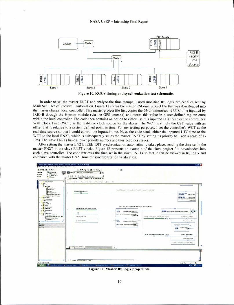
figure 10. KGCS timing and synch roniza tion test schematic.
In o rder to set the master EN2T and analyze the time stamps, J used modified RSLogix project fil es sent by Mark Schillace of Rockwell Automation. Figure II shows the maSler RSLogix project file that was downloaded into the master chassis' local contro ller. This master project fil e first copies the 64-bit microsecond UTe time inputted by IRIG-B through the Hiprom module (v ia the GPS anten na) and Slores this value in a user-defined tag st ructure within the local contro ller. The code then contains an option to either use this inputted UTC time or the contro ller's Wall Clock Time (WCT) as the real-t ime clock source for the s laves. The WCT is simply the CST va lue with an offset that is relative to a system defined point in time. For my testing purposes, I set the contro ller's WCT as the real-time source so that I could control the inputted time. Next, the code sends either the inputted UTC time or the We T to the local EN2T. whi ch is subsequently set as the master EN2T by sell ing its priori ty to I (on a scale of 1-128). The s lave EN2Ts have a lower priority number and thus becomes s laves.
After setting the master EN2T, IEEE 1588 synchronization automatically takes place, sending the time set in the master EN2T to the s lave EN2T clocks. Figure 12 presents an example of the s lave proj ect fil e down loaded into each slave controller. The code retrieves the time set in the slave EN2Ts so that it can be viewed in RSLogix and compared with the master EN2T time fo r synchro nization verificat ion.
.. ...... _--------aI# Q] e ] , .. . -. -... /11 . ..... -. -.-.. .. ... --.. . ..
.. ,.~ /10 [l l -.re.. 1
"i" 1ft - t".1'_""l17"·"·_ '" 3~ .:I .=:.LLJ •• ! .. Iot-Iul .!l
J.I ~'- A QW 1 ...... 1.1 ' ... (= Xi
I~~=~-....:.. I e . 1 r · .... --~- . .. '-. Ii'::'· .. ~
. """-~ ..-.... _ _ r_ .-._----..... '-.. -..... ..-.... ...... . -.. -. . .................
-'-.. ~ "' '-'. ''''-'1-. ~ r.1:=::"~--.--
- .,
IL·::..._- -_· _ --._ -_ -_ • • .J~~~
'" " , S'JTf .. , • • ... • , i
Figure II. Master RSLogix project file.
10
. !
.,

NASA US RP - Internship Fi nal Report
." .- , " .. ~ •• , .' I • I ... ,~.. ...". _I _ ~ Si
" ..... _---- ,-- -111 . .... -• _ _ 0-
,; 1"_00. ~ • ...o ao.
-.--. '-... - '''' .--- .. t =.:: "; ""'-_- 1-
--== '.;.'l D . .. ,_ "---. .:. ~-eo _ . r. ~_ c. __
;,J l_ "', t,OO"""'_ ...... _, .... ,
" (0),,.....-.' ........... ' . , (tj'-"""-.I
A _
_._ CtT_ ....... ,""'·_,_ .. ""' ............ "" _ .... ~., ..... _,.,,_' <St_ ........... =~."' .. ~ ... _~ ......... _ ..... ". __ .. __ , .. ..:,;:;:;==::~:.~":'.-::o:-..':-":'~ .. ..:..'='=::::::::::::..~::..";.:::_~
": ,,~,,. ." .... • ~ .- .. ) . • t!
Figure 12. Slave RSLogix project file.
V. Results
A. Latency and Jitter A few interest ing results can be gleaned from analyzing the data in Table I of the Appendix. Latencies were
generally in the range of 8 - 34 ms, while jitter was typica lly 5 - 20 !TIS. These latency values indicate a significant time delay, considering the fundamental speed of light delay fo r the trip fro m the Lee to the launch pad (and vice versa) is in the tens of microseconds. When conducting the tests, in almost every case the latencies consistently decreased from the max to the min va lue, before jumping back to the max value and repeating the process. Thi s demonstrated a periodic alignment pattern of the RPl s and NUT, which could be expected frolll the intrins ically periodic nature of the RPls and NUT.
Most of the tests where the ControlNet RPI was increased from its nominal value of 10 ms resulted in an increase in the max and mean latency values, with the min va lue staying constant. For example, in Test #5 the Contro lNet RPI was increased to 50 ms, produc ing a 40 ms jitter due to the raising of the max latency value to almost 54 ms. This is intuitive, as increasing RPl s should resu lt in longer time delays, especia ll y fo r the ControlNet module, which regulates the communication speed between local and remote chass is.
Keeping the RPls constant while reduc ing the NUT produced mi xed results. As Test #8 displays, decreas ing the NUT to 5 111S while keeping the RPls at 10 illS produced a lower mean, min, and max latency, though the j itter stayed at the same 10 111S value as the nominal case (a ll RPls and the NUT set to 10 ms). However, keeping the RPl s at 10 ms while changing the NUT to lower va lues, such as 2 ms in Test # 18, actua ll y produced higher mean, min, and max latenc ies. Discrepancies like thi s proved the unpredictab le nature of changing RPl s or the NUT. RSNetworx scheduling only guarantees that the set RPl s and NUT are the maximum update times, but that lower times can be permitted depending on schedul ing parameters. There is also no way to observe the actua l update rates on the backplane to construct graphs detailing the patterns g iving rise to the max to min latency precession.
My latency and j itter testing was more of a lesson on how to measure these va lues in a network than a concrete examination of solutions for the timeliness and consistency of KGCS PLC communications. Without the abi lity to directly observe the actual RPls and NUT rather than the values set in RSLogix, no formal conclusions can be
II

NASA USRP - Internsh ip Final Report
reached on the best method to reduce the KGCS' latency and jitter. The most noteworthy result of my latency and jitter testing was that the PLCs themse lves produced the most time delay and unpredictability in the network. Millisecond latency is important to understand in time-critical appl ications such as the KGCS, where the motion and condition of thousands of valves, switches, and heaters must be continuously monitored and cont ro lled. Further latency and jitter testing within a more reali stic scenario wi ll provide more accurate ins ights into the timing characteri stics of the actual KGCS PLC network. .
B. Time Stamping and Synchronization Upon downloading the master and slave project files to their respective controllers, I set the local controller's
WCT to the current local time, and then observed the timing and synchronization resu lts in RSLogix , Wireshark, and the EN2T webpages. The first step was to check the master EN2T's webpage and RSLogix project file to confirm that the local controller and master EN2T had, in fact , been set to the local time (5 :3 7 p.m. ET on May 5, 20 10).
Figure 13 shows the two tags (CurrentTimeM icrosecondsGMData[OJ and CurrentTimeMicrosecondsGMData[lJ) that store the 64-bit microsecond UTC time, that in this case, comes from the local contro ller's We T (rather than the typical GPS signal). A rough calculation shows the number of microseconds that had elapsed s ince January I, 1970 (as of May 5, 20 I 0):
(60 seconds/minutes) x (60 minutes/hour) x (24 hours/day) x (365.25 days/year) x 40 years + (86,400 seconds/day) x 125 days ~ 1.273 104 x 10' seconds or 1.273 104 x 10 15 microseconds
" II\l ,,, .. ,ouo 11 .... ~nl Itl""W M, h' 11/," II II I( """,,110 ' 1m IIIPII( IM I,,,,,,,, M"", I' ",1,,,11., II
I ·11 ::J " I' lcal ll> 'I "I I I 3~ III • A",Moc!o
~ • CoffloW OK a! r B.llet)OO~ • 110 OK
1-~ c __ rllPl'tOM_''''"''II __ •
Jj C _ _ t .-;JI
~ C(nll" f_"""" D _-u.tIar"deo
- i;S 1_ _ ~h~
- ':1 001 ....
t= . OIIGPS . Ol,"'pcts.c.co
11 olCSTMoo-l • .PtrI~ ':::' ~Pr""'_ I_
- 9_~
CJ 1.roQrWC*i "" .. C:l Ado<In l,*,uttlO"><
- ~ D.oI:.T_
• ( j Uw.(le/.-..d • Lj Sb"1'9'
'ol-"" • Ci PtKlol.-.:l • ( j_..-oom.a
D I,ena. I/OCorl"lOII.oI"",
- . ~~~.I7S6-A1
~ k'!iI P«h; 1~_EHIIP.1\1 n.27S.UI\8~\O
.!J I I I I I I I I J.Ll.J\ A A A A
,-. '""'"' TonolHe: I ... )
-c","'TiooeM~IoIO" ( ... ) +tt-.lT .... ~-..(tlI 14S60166H
+ c.-.IT .... ~tU(l1 He4U ~M_
+E .... _~ ..... ., E~MtlMSo;ua " , ............ , . -"""'" ( ... ) + OIISIwt£N2TCSTMIII ( ... ) + toIoICb:tI .... ( ... )
toIoIEN2Tc-.Etl!obW.d
"""","",IS-+~lo..ta , -"" ( ... ,
+ GPS.o.to..G m GPS_Wodl./olOk
GPS.GPSI.cd. GPS_CSrOk. GPST-.o~
Figu re 13. Local controller time tag.
~ A
·1 ti
o. ( ... ) D-* " ( ... ,0---, " 0_ " 0_ " D_ OC
0 ..... " 0.- OC D_ OC
( • •• 1 ., ( .. · l .. I ... ) '" D_ OC
O_ OC D_ .,
I . .. ) " D_ •. D_ OC D_ OC D_ OC D_ OC
Figure 13 shows a value of 2964 15 in the most significant DINT and 1456076674, representing e lapsed microseconds, in the least significant DINT. Due to the decimal format in which the tags display their va lues, the least significant DINT counts through 4,294,000,000 microseconds before incrementing the most significant DINT by I . Therefore, the tota l number of microseconds that are displayed in thi s 64 -bit va lue:
296415 x 4294000000 + 1456076674 ~ 1272807466076674 microseconds o r 1272807466 seconds
This compares favorably to my rough calculation above, within the accuracy of no t accounting for leap years and conducting an exact calcu lation. However, an exact calculation does not need to be conducted. The webpage for the master EN2T. shown below in Figure 14, correctly displays the UTC time set in the maste r EN2T. As can be seen, the UTC time is listed as "05 May 2010 17:37:30," indicating that the master EN2T's clock had , indeed, been
12

NAS A US RP - Internship Final Report
changed to the local contro ller WCT that I had prev iously set to May 5, 20 10 at 5:37 p.m. ET. Note that the "Is Synchronized to a master" line on the master EN2T webpage is "False," since the master EN2T is not connected to a Grandmaster source. I suspect that actua ll y connecting the facility IRIG-B coax line 10 the Hiprom module will change this value to "True," as the Hiprom module would then act as the Grandmaster time SOU Tce. The "Grandmaster Time Source" line lends further credence to this theory, as it displays "Hand Set," which was what I did by manually setting the local cont ro ller WCT. The "Port 2 State (Ethernet)" li ne says "Master," deli neat ing thi s as the master EN2T and the "Local Clock Identifier" line labe ls master clock's identity as "0000bcfTfe3f8987."
3 , .,_, . , _, t. , ... . , '"'' ""I~' , ... (41_·_ 1_ .....
ct>o" .•
.... c_. I, ............. J •• • ~ . ". ... _",.'~I.-
~.,. ...... " .( .... I' .. . "" .......... . . t . . . .... ,.,
"' .".~ . " ........ ,
_ .... <.Iodo Ic .... ~ •• _ .. ~C( . ..
..... eIN ..... _
.... 10<0"' ."."">
.... , ..... " .... ~. ,
._ I e ............... .
Figure 14. Master EN2T webpage.
-. .... -"" ...... ,
-_ .. ' "'-"" ..... ., ,"
...
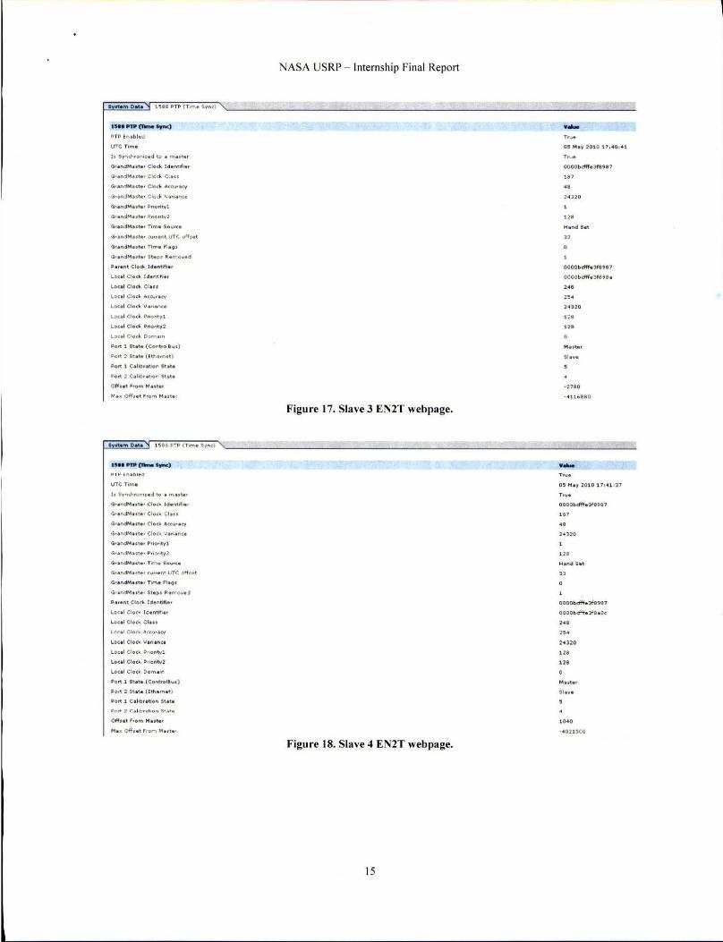
Now that it was clear the maste r EN2T had been correctly set, I needed to verify that the slave clocks had been synched to thi s time. Figures 15-18 show the webpages for the slave I EN2T. slave 2 EN2T. slave 3 EN2T, and slave 4 EN2T, respectively . All of the UTC times are within minutes of the maste r EN2T UTC time, which is within the speed that I could obtain screen captures of the webpages (in real-ti me, the master and slave UTC times exactly matched). The "Is Sychroni zed to master" lines changed to "True," indicating that the slave EN2T clocks were synched to the master EN2T clock. The "Grandmaster Clock Identifier" and "Parent Clock Identifier" lines for each slave changed to "000bcfff.lf8987," which was the unique identifier of the master EN2T clock. The "Port 2 State (Ethernet)" lines were all li sted as "Slave," as was expected for the slave EN2Ts.
The next step was to ve rify that the two "CurrentTimeMicrosecondsGMData" DINT tags contained in each of the s lave RSLogix project fi les were set to the correct microsecond value. Figure 19 displays the two DINTs for the slave I contro ller; the most significant DINT is 29641 5, whi le the least s ignificant DI NT is 1502028365. This is within seconds of the master EN2T 64-bit UTC time in Fig. 13, aga in acceptable given the limits of the speed at which I could obtain screen captures of the tags. The slave 2, slave 3, and slave 4 proj ect fil es a lso conta ined values match ing the time in the master EN2T. All of these resu lts indicate that the slave EN2T clocks were accurate ly synched to the master EN2T. The next step was to veri fy the actual IEEE 1588 communications.
13

NASA USRP - Internship Final Report
• _ Otot. :518 I>TP (Tim . S,"cl , ___ -=: ___ =-:::..::..:====-=====:.:--.:==-=-==========-______ -==== u .. ~"'c--. ....-) PTP ( ".101.01
IITC T,m.
I. "."h.o, .... d to. "' .... '
a •• "dP"lut., Clod< Ld.nttf; .. ,
(I • • ndMuU, Cloc\. (:1 . ..
(k.ndMut.o. Clan. .... OJ,."
(I •• "dM •• te, T,me Iou.,.
(I .ondM.OI •• < .. ".nt UTe off ... t
(I .""d"' . .... T,"'e FI .~ .
~.'.nt (:10<10 Id.ntifl ••
~o<.1 Clod< Id."t>f,o.
Lou! Clod< (:1 ...
Lo,.1 Clo d- " «"'" CV
lO'" Clod. .. "..;"" ..
Lo'" (:10 6 P' ,o _,t.l
Loc.! Clod>. .. ., .... ",1
loW Clo d- 00"" . '"
POf\ I 'ta'e (Co",," .. I1 ... )
I>Cf\ 2 " 0'. (I." •. ".t )
Port I C. . I,b. abon I t • ••
POf\ 2 C o l,b. oo o n Stote
Off ... '.om Mano,
UM '""' ewo- ...... ) PTP f nobl.d
UTe ,,"'.
".and"'." • • Clo " CI . ..
(I • • "clM •• t. • ." .... Sou,,_
>l' .n~M .. " " <u". M UTe off .. ,
Gf o"d~ .. t., 'TIm. ".g<
" • • oM Cloo. Ido "tIft.,
~o<.1 Clo<~ ld. ~tl" . ,
~o ul ':;10'" .''''''0 <,/
1.0<01 Clod. VO " O ~""
~o<ol Cle<~ P,l o"t~1
Leeol Clod. P"0'''~1
Lee ol Clo,>. Oom.,n
I>ott 1 Sto •• (Co"""Il". )
I>ott ~ ".'0 ([", •. ~ ., )
I>ott 1 C .I, b ,otJon . . ...
... . . Off ••• ~'O'" ........
Figure 1 S. Slave 1 EN2T web page.
Figure 16. Slave 2 EN2T webpage.
14
.... l ....
OOOObcfff.3ftlu,
." .. 2. nO
". "
OOOOt:";lft'd",,,
OOOObdH.3f8" .
". ,,. 24320
'"
-10340
- ' 019780
.... OOOOl>dff.m",
." .. HHO
'" "
OOOObdff.Jflltl7
COOCbdfl. :lf8~',
". ,,. ~ .l~O
'" '"
..,
~---------- ----------------------------------------------------------
IS .. PYli en.- fync)
I'T P ( ... bl.d
G,end", .. t •• Clod< Id ontlfio.
<3'0 .. <1"' ' ' \0' Cioo Clu.
GrandM a .to. Clod. Acru,acy
(I.ondMost •• CI"o. "' ."OMe
G.ondM •• to, """my1
(1.o .. d", • • to. C\J"ont UTe off • • t
(i.and M •• t •• Tlmo flo9 '
Po,onl Cloe>, Idon\,".'
LP,. I Clpck Id e M,f.o ,
Loc.1 Clo .... CI ...
Loco l Clod. Accu,ocy
Lou! Clodo. V.".n,.
Loc.1 Clock !>no ntvl
Loul Clock Pnofltv2
Lo,.1 Clod<. Do",., ...
Port 1 ,t.,. (Con ... ol ..... )
Po" : St ot t (ith . ",. t )
Port 1 Coltl>,Ulon Stoto.
I. Syncn.on ... d to . m .. t. , G •• ndM .... ' CloOo. Id.""fio .
G'.ndM . ... , <; I o'~ CI .. .
G. and"' .. , • • Clock ....... ,. <\1 0'0 .. <1/01 .. '0' C lo .... Vorl . M t
(j.ondMuto, Prlp"lyl
G'. n dM . .... , P"" " \V2
G'.ndM . .... Tlm. $0 .... '.
Po,.n. Cloo. 1<I.ntlf!a.
Loc . 1 CIQ" Id.Mm ••
Loul Clock CI ...
lo,.1 CI ",1o. A"" , .,~
loul Cloo. Va.I. ",.
Loc .1 Cle,1o. ~ "orit~l
Lo • • 1 Cle." ~ rlerlt~ 2
Lecal Cle,k Dern . ,n
~ o'" 1 at ... (Convol'~.) Pol'! ~ SlOt. ( hhaln.t)
Pol'! 1 Cahb.atlen St.t.
NASA USRP - Internship Final Report
Figure 17. Slave 3 EN2T webpage.
Fig" re 18. Slave 4 EN2T web page.
15
.....
OOOObcfff.3fU87
'" ., 24320
"
OOOObdffo)f8,.,
OOOO bd'ff. 3f99e. ,.,
1 ~8
-neo "41H.B80
. .... 0 ' Ma~ :01 0 111 4 1 , ~7
Tt~.
OOOObcfff .. 3fBIJ81
'" •• 24320
"
OOOObcfff.mIJ87
OOOO bcfFf. 3Ihe.
,., '" Hl20
'" no
M •• toII

NASA USRP - Internship Final Report
SCOQe: IIt!J HIPROM_ T mll'\!;.:::oJ Sh2w .. , I csto_CSl andSystemT ime. Ctto_CS TInfo. ctto_SI&ll.n8h. DEVlCEJD. GPSCA/tesi¥l, GPSENU, GPSlrnage. GPSPoier. GPS
N_
+ I.weEN2TCSTM
GMEN2TComEMbbhed + .,... + l MtS),$IemSl!ICOrlCIs
MarwlySetGMCSTMasleId'ip
+ NewCSTMosteunpOato + OcXl:hecklnt
+ ONS3
Secorx£lep$ed
+ Serd3MCSTMatleld'ipO_1
+ SetGMCSTtoIasteltt., + SdGMCSTMa:lent.,,,,o
SetGMCSTM.ster~qaied
- S~N2TfSTlrlo
+ S~N2TCSTlnfo.StatlA +, SI.weEN2TCSTlrJo.CSTV~
- SI.weEN2TCSTlrio.S~emTine
+J SIweEN2TCST lnfo.SystemTine(Oj
l+ SIaveEN2TCSTlnfo.S)'stemTime(1 ) + SlaveEN2TCSTlrlo.SystemTineOfb et
+ SOECSTInfo
+ SystemStICQ"'I(b
Data T
( ... ) t .. · ) MESSAGE 0 Decimeol BaOl
7573 Decfllai DINT -1 959 Deem'" DINT
0 Decmal BaOl
Decll'Ml SINT
0 Decfnal OINT
0 Oocrn> DINT
0 Decirnlll BOOl ( .. . ) ( ... ) TIMER
( .. . ) t .. · ) MESSAGE
( ... ) ( •• • • Decmal SINI I2) 0 Deemal BaOl
( ... ) ( ... ) cao_CST ardSystemTime
Deemal DINT ( ... ) ( •• • • Decrna/ OINI I2) ( ... ) ( •• • • Decimal DINTt2J
150 202836 5 Deem&! DINT
296 415 DeCimal DINT ( .. . ) ( •• • ) Decmal OINII2) ( .. . ) t .. · ) ctto_CSTlnlo - 1959 Decm.!ll DINT
Figure 19. Slave I time tag.
The Wireshark software program a llowed me to view the packet-by-packet communicat ions over the network's Ethernet line. By applying fi lters. I li mited the visible traffic to PTP messages from the master EN2T's IP address. The results are shown in Fig. 20, with each line representi ng a separate data packet. The "Time" colurnn displays the number of elapsed seconds since the beginning of the run, the "Source" colurnn indicates the packets are sent from the maste r EN2T IP address, the "Protocol" indicates PTPv2 for version 2 of the PTP, and the "Info" column shows the type of message being sent. It can be clearly seen that a "Sync Message" is sent from the master EN2T about every 1.009 seconds, ver ifying Rockwell representat ive Mark Schi llace's statement that sync messages are sent once per second.
Figure 2 1 shows a breakdown of the sync message content , specifically the time stamp. The blue highlighted portion of the data packet indicates the 48 -bit seconds portion of the time stamp, coded here in hex format. The "originTimestamp (seconds)" line lists 127306806 1, which matches my rough calculation and the RSLogix values for the number of seconds e lapsed since January I, 1970. Figure 22 displays the 32-bit nanoseconds portion of the timestamp, which is stored contiguous to the 48-bit seconds within the IEEE 1588 data packet.
Observing Fig. 20-22 reveals an interesting characte ri stic o f the IEEE 1588 communications. The lines labeled "12" and "1 3" in Fig. 22 are de lay req uest and delay response messages, respectively. These two messages are sent much less frequency than the sync and fo llow-up messages. Figure 23 revea ls the breakdown of the slave 1 EN2T's message count over a given time span. Over 100,000 sync and fo llow-up messages were sent/received, while only a little more than 3,000 delay request and delay response messages were sent/received. Thi s demonstrates that the IEEE 1588 algorithm l11ust be more concerned with correct ly adjusting the master-to-slave message de lay more than the s lave-to-master delays.
16

- -- --------- --------------------- --- -
NASA USRP - Internship Final Report
" "." ", I.. . .. 'x
, Fr ... I (ll>C> 0)"1" "" wlr., l66 0)"1'" <~ ... Ild) • Eti'>er_ II, Src: lochiellJ':89:81 (00:00:1><:)f :19:11), 0 .. : : ........ "_00:01 :11 (Ol : OO:S~:oo:Ol:Bl) , Intlr ...t ... <rtIKol, vc : tn.l7. I.UI (111.11.1. 101), DI", IH .O. I. llt (l lO.O.l.ll9) · (H'" .''"gr'' .... "'tK0 1 , YC Por t : ptp- .... o-nt (JU). on ~"": otp-r-ent (H9) • ... ..,10 1"" TI .. ...... tKOl (IUUIII)
"'" 'C ~~I\C(Itf'IIO-,-..cou.-'\l • • _ .,., _ .. _ ,."'_0 _001..., '-o SlIIrt •• • • 1 ... " •• • _. " ._ ~, ' . II!! '
Figure 20. Sync message from the master EN2T displayed in Wireshark
I ,.1'"," "... _ (' ')( tftotd<"... ... ~~_.tIO'>
.111. IiII II f- !dX " ,;;, . ~ .. -.
''''''_11-''0",: 0 • f 109>: 0 _0100 • corro"I",,: 0.000000 n.nauc",,",
c l od I O ... ",y ' 0.0000~t~h)fln1 So ..... ' ... "" I O: 1 .. ooenc~ ld: 11H l
''''''' 0': sync M''''~' (0) ' D(J'<e. U')I!POrIO<l: 0
01 00 \I 00 01 Bl 00 CO 00 ~8 1 1 ell oa 00 ot 1) 0181.011f011fOO 80 01 00 00 00 00 00 00 00 I><: t ' 101f8981 0001 _ IS ~ 98 f>O 00 00 ~ ooooooooooao 00 00 00 00 00 00 00 00 00 co 00 00 00 00 00 00 co 00 DO DO 00 00 DO 00 000000000000
Dc1flg 81 08 00H I O )I 1. >< I . OJ 80 ItO co M !ldl00100Uoooo 00 00 00 00 00 00 00 00
~~gggg~ 00 co ~o 00 DO 00 00 DO 00 00 00 00 00 co 00 00 00 00 00 00 00 00 00 00 00 00 co 00 00 OC 00 00
.. ' .. ::::.: ":: •...
~ ... , . 17 .. ..
:: .. ' : SIIrt .•• j- - • •• • - , " . ~.
Figure 21. IEEE 1588 48-bit seconds timestamp.
17

r------------------------------------------------------------------------ ----
NASA USRP - Internshi p Final Report
, ' .. " ~. ~. , . .. 'x t.to.,.,...~ ~ _ s-u ~
~" . IiW* ' 1iJ!lC 2 .:o) . ~ • • ,,'f'J: ...
I~gdooi,,~o.r; 0 • fl '9': 0 . 01 00 , co""e\ ton: 0.000000 n . ....... e""". 'lodl ~Of\t\ ty : O. 0<XXl""f ff l l"U87 so"'", ... "' <l O: l .. _n<.I ~ ' 11<11 con",,': S)"'c .... ...... ( 0) lo~ • • • ~dO<l : 0 .". ' 91n'l ..... .. "P ( ,KO'I<I'): l.l 7)068ot.l
Ql. OO h OOOJ. &l 00 00 00 ... " I d1 00 00 01 11 00 1l0l I f Q!)f OO IlO 02 00 00 00 00 00 00 ~O "" f' '', ' '' U87oo01 ~n:: ftIIft gg gg 00 00 00 00 00 00 00 00 00 00 00 00 00 00 00 OQ 00 00 00 00 00 00 00 O~ 00 00 00 00 00 00
IKH l it1 0a OO HtO 11 7. I e 11> 0 \ B~ to 00 611 8<1 1 0 Ql 00 Ie 00 co 00 00 00 00 CO 00 00 00 J.< 00 00 00 00 00 00 U 00 00 00 00 00 00 00 00 00 00 00 00 00 00 00 00 00 00 Q~ 00 00 00 00 00 00 00 00 00 CO OQ 00 00 00 00 CO 00 00 00 00 00
.. ' .. . ~ • • , i • n . . L.
.: :;::: .:: 7._ .
.. .,' ____ o1.ot;::"====4iot """. '_"","","",1:21 _ ,0-' 0
"JSI"11' 'T , ,'.' .. • _,. _ • ". ..
Po rt 1 A""ouncI m .... g. count
Po rt 1 Br'" m . .. . 9. cou nt
Po rt 1 Foil .... " " ..... . ., 1 '01 " count
p".t 1 D . I I ~ R. q m . .. . g. co" n!
Pe <\ 1 D.I . v I\ . , p "" .. n \l _ co""t
Peot 2 Sync "". " '\1_ co"nt
1'0<\ 2 Follo" "p ........ . \1. CO"M
1'0 <\ 2 D. I . ~ I\.q ..... . ... \1 . co"n!
1'0 <\ 2 D.la v 'h. p "''''' \I I co uM
Figure 22. IEEE 1588 32-bit nanoseconds timestamp.
Figure 23. Review of slave I EN2T IEE E 1588 message count.
SU 68
103'11
103 ' 00
3291
321 0
The final test to perform involved disconnect ing the master EN2T and observing the communications that take place in estab li shing a new master. Once the master EN2T Ethernet cable was di sconnected, various sync and follow-up messages were observed; however, these messages originated from the slave 1-4 EN2Ts rather than the master EN2T. Interestingly enough, after the negotiating back and forth, it was the Gateway server that consistently took over as the master (IP address 192. 168.168.3 1). The master negotiation was usually comp leted within 10- J3 seconds. Figure 24 shows the slave 3 EN2T webpage immediately after the master Ethernet cable was disconnected and before the Gateway server had taken over as master. The "Is Synchronized to a master" line now shows "False" and the "Grandmaster Clock Identifier," "Parent Clock Identifier," and "Local Clock Identifier" lines all show the same clock identity. namely, that of the slave 3 EN2T. Also note that the ·· Port 2 State (Ethernet)"" line indicates "Master" as this EN2T is no longer connected to a designated master (in which case, this line would still be "Slave") , "The GrandMaster Time Source" has changed to "Internal Oscillator," which might suggest that the EN2T is serving as its own master.
Thirty seconds later, Fig. 25 shows the result after the Gateway server has taken over as the master clock source. The "Is Synchronized to a master" line is now "True" and the "GrandMaster Clock Identifier" and "Parent Clock Identifier" lines have changed to different identities (the "GrandMaster Clock Identifier" is most likely that o f the Gateway server) , although the "Local Clock Identifier" has stayed the same (as expected, it is unique to the slave 3 EN2T). ··Port 2 State (Ethernet)"" has switched back to '·Slave·· now that the EN2T is once again synched to an
18

NASA US RP - Inte rnshi p Final Report
outside master. For reasons not fully understood, the "GrandMaster Time Source" is st ill listed as "Internal Oscillator," even though the Gateway server is now the master clock source .
• _ ... 0.. I ""i PTI> (T,"'. Sync)
IH.""'o- ..... ' HI'in.b!ood
UTe T, .... .
Q, . "dM .. t.. Clcck ldof>tj" . ,
Q . . ... dfot •• t., Clod< CI . ..
Q. ondM orto , Clocl<. ..... c .. ,. <'/ (I .ondM •• tt. Clcd< v, ,,o nto
Q. ond M •••• , 1>010. 1<:,1
CI, _ Moot., TIm. "6<1' (;, on4", ... 0 , Sto p. Romo • • d
p_"" Cl ..... Ido"tIfI.,
\.e • • 1 (: , .. <1- l do n"".,
locol ""do .o.a." acy
Loc. ' Clod "' ... ,,,,,,.
I.o u i Clod< g"C....,1
l.Ou l ~ ....... 1> ....... y2
~ul el" .... Dc ..... . . ...
",,",1 !.oto (Corwole" . )
I>on : i •••• (I <h . ",.t)
1',,", I C.~I>,.bon "ot.
IS .. ~'" en.- trM)
PTl' ("<bl. d
UTC Tit" .
I. 5 ~ncl'l,on' .. d 1o . ", • • t. , a •• ndMu h . (100. Id. ntlfl • •
Qr.ndMuu' ~ I o,k CI ...
a •• ndM ... . . ( 100. ... ,""r .... Q •• "dM .... , (Io<k " . ~ .M.
a •• ndMo rt • • p"otltyl
G' . ndM . ... ' p """.~)
(I ,ondM.,t . , Tim . I"" ...
.... naM .. I • • <,/n.'" UTe of h • •
(I, . nd"' . rt. , Tlm o ".g. a , ondM o,'. ' ItoI" ~.",o. o a
P ... ... CI ...... Ido n tlfi.,
Locol Clo do Id o " td,o,
Loul CI .. 6. CI ...
Loui Clo d- Accu .. ""
Loul Clo6. Y. " " nc.
Locoi Clod- P"o"tv!
Lo..:o1 Clo .... P ..... "tv l
l"col Clo6. Oom • • "
' .. ,0: 1 St u. (C .. .,troll" . )
1'0 ,0: 2 I Uto ( UI'I.'''o')
1'0,0: 1 C.I,b,.Vo n ' Ut. 1' 0 ,0: 2 e .llb •• tlo., Stu.
Figure 24. Slave 3 [N2T webpage, master [N2T disconnected.
Figure 25. Slave 3 EN2T webpage, Gateway server as master.
.-0' "'0, 2010 2(1 ,2' ,12
~.I • •
oooot>dff. :aft, ..
". '" ~0120
'" '" 1" " "'01 O.",Jl.ta.
"
OOOOlldff."" ..
OOI)O~dI'f.)fUIa
". '" HUG
'" ".
.... n.'
.-TN. 0' Mo y :Ol O 20,'0,0:
00DO bdff. ld21 n
". ,,. :.no
'" '" "
OOOObdff. 3 .. bb 4
OOOObcfft. l , 8 ' 8 .
". ,,. : ono
'" '"
Upon reconnecting the master EN2T Ethernet cable, master renegot iation once aga in took place, although this time it was genera lly about 9 seconds before the master EN2T had reestab lished itself as the master clock source. This verified that the RSLogix code succeeded in successfull y establ ishing the local EN2T as the master every time that it was connected to the network (remember, the code sets the local EN2T priority to I ).
One extra test that I decided to perform highlighted an anomalous result that must be examined further. I changed the local contro ller's WeT to June 5, 20 11 to see if the master and slave clocks correctly changed to this
19
NASA USRP - Internship Final Repon
new time. In RSLogix, the "CurrentTimeM icroseconds" tags changed to 333 71 for the most s ignificant DINT and -15553 15787 for the least sign ificant DI NT, indicat ing a large increase in seconds, which was to be expected for moving the data 13 months forward in time. However, the tags within the slave project files did not update to this value. The slave tags stayed at their previous values, counting on May 5. 20 I O. The EN2T webpages all st ill showed a UTe time on May 5, 20 10. Within Wireshark, one of the sync message time stamps contained a 48-bit seconds ponion of 12730966 1, indicating May 5, 2010 once again . If the RSLogi x project fil es were working correctly, resetting the local controller's WeT should change all of these timing va lues to the new set time. This was what happened when I originally set the local contro ller's WeT to May 5, 20 I 0, but is unclear why setting the time forward 13 months d id not change all of the timing values aga in.
VI, Conclusion
These test results will prove useful for the Constellation Program's KGCS o r any other ground support system at KSC, regardless of the Constellation Program's future. Further tests must be perfonned under more rea li sti c conditions to accurate ly measure the latency and jitter with the KGCS' PLC network. The latency and jitter tests that I conducted merely demonstrated that the PLCs themselves produced the most time de lay and unpred ictab ility in the network. Since the actual KGCS network will have many local and RIO chass is connected, I would recommend performing tests with many RI O modules. Including more modules, each with their own RPl s that must be scheduled along with the NUT, may lead to further time delays that will be important to understand in the operation of the KGCS.
The timing and synchronization tests verified the IEEE 158 8 communications between the master and slave EN2Ts. Synch messages were sent from the master EN2T to the slave EN2Ts once per second, with the time stamp stored in 48-bit second and 32-bit nanosecond portions of the data packet. The master RSLogix project file successfully set the local EN2T as the master, with the local EN2T establishing itse lf as the master any time that it was connected to the network . The 64-bit microsecond UTC time sto red within the two DI NTs was correct ly synched between the maste r and all of the slaves. Code can be eas ily written to add these two DINTs to the data packets sent to and from the LCe. Considering the 64-bit microsecond UTC time was correctly synched to the slave RSLogix project files, ti me stamping could be done at the RI O chass is, though this would consume more bandwidth. Whether data packets are time stamped at the local contro llers o r the RIO chass is is also dependent on the des ired level of time stamp accuracy, Further testing remains in connecting the actual IRI G-B line into the Hiprom module, rather than simply setting the local controller's WCT as done in this test scenario. That will be a more accurate simulation of the KGCS' operation, since it will actually use the G PS signal fed through the IRIG-B line.
h is unclear why the Gateway server consistently took over as the master rather than one of the slave EN2Ts whenever the master EN2T was disconnected. In actual operat ion, the KGCS wi ll most likely contain a second Hiprom module with a redundant master EN2T. Testing must be perfo rmed to understand how the redundant master EN2T wi ll ensure that it ga ins mastership in the event that the true master EN2T is disconnected from the network. Perhaps setting the redundant master EN2T's prio rity to a number such as 2 (anything greater than I) wi ll a llow it to seamlessly ga in mastersh ip.
20

----------------------------------------------------------------------------
1 NASA USRP - Internship Fi nal Report
Appendix
Table I. Latency and Jitter Test Measurements. (A I/limes in milliseconds)
Test eNel 181 6 0 8 8 NUT Mea n Min Max Jitter Sdev Num Run RPI RPI RPI
I 10 10 10 10 18.49775 13.93789 23 .94 103 10.003 14 2.743898 4 16 2' 10 10 10 10 18.85436 13.9798 23.9997 10.0 199 2.9037 920 3 15 15 15 10 18.9922067 13.88858 23.99545 10. 10687 2.9 1576 17 240 4 15 10 10 10 18.8476676 13.94968 24.21920 10.26952 3.0826042 508 5 50 10 10 10 33.9632022 13 .93435 53.97385 40.0395 11.5566852 932 6 10 10 10 10 19.031 1232 13.93227 23.9945 1 10.06224 2.79 11 976 252 7 5 10 10 5 11.47435 18 8.82689 13.92 154 5.09465 1.488855 528 8 10 10 10 5 14.0318095 8.8 1429 18.875 15 10.06086 2.923 1947 248 9 5 10 10 5 11.3907800 9.00538 13.87184 4.86646 1.4 178859 120 10 10 10 10 10 19.0485609 14.00528 23.96837 9.96309 2.8996222 244 II 10 10 10 10 18.9560578 13.92333 23.97040 10.04707 2.8866426 232 12 10 10 10 10 18.5818042 13.94683 . 23.98406 10.03723 2.8374690 208 13 10 10 10 10 18.5965723 13.94688 23.90098 9.954 1 2.7612430 228 14 10 10 10 10 18.9779382 13.9682 1 24.02265 10.05444 2.9771858 248 15 10 10 10 10 18.8074736 13.89259 23.8236 1 9.93102 2.9 145254 232 16 10 10 10 5 14. 1317429 1 9.03429 18.85272 9.8 1843 2.8242465 222 17 10 10 10 2.5 21.4667808 16.485 12 26.44 103 9.9559 1 2.8478809 240 18 10 10 10 2 21.7063236 16.5 1443 26.45 197 9.93754 2.94 19 11 8 208 19 10 10 10 2 2 1.40732 18 16.52802 26.52379 9.99577 2.8835 176 224 20 10 10 10 3 21.5254664 16.55163 26.4828 1 9.93 11 8 2.8885815 232 21 10 10 10 4 21.5336290 16.56085 26.5 1604 9.955 19 2.9022578 232 22 10 10 10 5 21.40678 19 16.40067 26.46037 10.0597 2.903332 1 240 ?' -, 10 10 10 6 21.5281259 16.52009 26.45726 9.93717 2.89 16269 240 24 10 10 10 8 21.5392955 16.49247 26.58923 10.09676 2.8860247 236 25 10 10 10 8 18.8873087 13 .9 1596 23.90899 9.99303 2.8553402 240 26 10 10 10 2 18.9072305 13.95129 23.90899 9.9577 2.5649835 300 27 10 10 10 5 19.5758522 13.89700 23.986 12 10.089 12 2.87038 14 300 28 10 10 10 2 18.97589 1 13 .98050 23.92894 9.94844 2.8623880 228 29 10 10 10 5 13.929 1956 9.00599 18.90289 9.8969 2.887495 1 232 30 10 10 10 2 17.4752607 13.466 10 2 1.52 191 8.0558 1 2.245779 1 196 3 1 10 10 10 2 17.5598902 13.46006 2 1.42 11 6 7.96 11 2.3340320 192 32 10 10 10 3 10.5542447 6.88057 18.01098 11.1 3041 2.2290055 312 33 10 10 10 2 25.4306889 21.46565 29.0025 8.3346 2.3247264 184 34 10 10 10 5 24.0511452 18.85277 28.99734 10.14457 2.960878 1 244 35 10 10 10 7 16.9995866 10.94310 24.95497 14.0 11 87 4.0974 194 252 36 10 10 10 9 2 1.086 1460 12.85 179 30.92694 18.07515 5.1963023 252 37 10 10 10 10 18.9297489 13.8807 1 23 .95761 10.0769 2.8211689 252 38 10 10 10 2 2 1.4962566 13.46 182 29.43626 15.97444 4.5284803 396 39 10 10 10 10 19. 11 4 11 97 13.99 129 23.9 1492 9.92363 2.84760 10 252 40 10 10 10 2 19.58 129 15 13.46026 29.47004 16.00978 4.5842105 472 4 1 10 10 10 10 28.9992358 23.9320 1 33.98043 10.04842 2.8695 171 484 42 10 10 10 2 17.6 169534 13.46693 21.58592 8.11899 2.4 15361 500 43 10 10 10 5 13.6662618 8.86377 18.95 187 10.088 1 3.0 168843 5 16 44 10 10 10 7 18.8335998 10.98 122 24.98992 14.0087 3.4936607 372 45 10 10 10 9 20.962 1513 12 .88946 30.93 100 18.04 154 4.9594706 464 46 10 10 10 10 18. 1544895 13.87298 23.99940 10. 12642 2.8056858 360 47 10 10 10 2 18.6230866 13.46799 29.50015 16.03 16 4.4887042 372
21

NASA USRP - Internship Final Report
Test eNet (B1 6 O B8 NUT Mea n Min Max Jitter Sdev Num Run RP( RP( RP( 48 10 10 10 5 24.0257228 18.82 100 28 .96982 10. 14882 3.092 1598 544 49 10 10 10 9.5 21.52 12609 13.47557 32.42338 18.9478 1 5.527 1953 452 50 10 10 10 5 23.8215433 18.89830 28.93302 10.03472 2.8462 151 456 5 1 10 10 10 7 18.1406772 10.93419 24.99672 14.06253 3.995184 444 52 10 10 10 10 18.1547620 13.89016 24.0 1314 10.12298 2.97 14 172 3 12 53 10 10 10 9 20.9 137687 12.98423 30.40336 17.9 1913 5.433 1450 384 54 10 10 10 5 24.237853 18.90366 29.00009 10.09643 3.2427983 3 12 55 10 10 10 10 21.2 178960 13.98026 34.24797 20.2677 1 5.06422 12 2,000 56 10 10 15 10 19.1362355 13.92755 24.06829 10. 14074 2.9 158596 2,000 57 10 15 10 10 27.43539 15 14.02887 34.06390 20.03503 4.6629030 1,200 58 15 10 10 10 21.40 12325 13.96736 34.0955 1 20.128 15 5.0476602 2,000 59 15 10 15 10 19.0561 108 13.97 107 24.07084 10.09977 2.8850225 1,600 60 15 15 10 10 19.6009793 13.93634 28.68453 14.748 19 3.4473884 1,200 6 1 10 10 15 10 24. 15 18155 13.9 1676 34.07583 20. 15907 5.8138599 1,000 62 15 10 15 10 18.7998455 13 .91356 24.00536 10.09 18 2.7793589 800 63 15 10 20 10 23.9021478 14.03923 33.99573 19.9565 5.5980853 500 64 20 10 10 10 19.027836 1 13 .86605 24.00887 10. 14282 2.8827965 1,560 65 25 10 10 10 29.0585773 23.87661 33.96900 10.09239 2.6668587 600 66 15 15 15 10 18.84 15854 13 .9 1499 24.02897 10. 11398 2.8874074 1,100 67 10 I I 12 10 18.966526 1 13.95 110 24.10566 10. 15456 2.8022222 1,000 68 10 I I II 10 19.0798 167 13.89 130 24.04535 10.15405 2.8 186088 1,000 69 10 10 10 10 19.0 114637 13.9133 1 24.07885 10. 16554 2.890483 1 1,860 70' 10 10 10 10 18.95 10028 1 13.9 13909 24.072793 10. 158884 2.928 19604 1,720 7 1 10 10 10 10 22.6325675 13.87375 34.05937 20. 18562 5.62 17632 3,828
*\ 0 Hz input signal t Tests #55-71 were performed within a 10 ms periodic task; the previous tests were conducted withi n a cont inuous task.
Acknowledgments I would like to thank my KSC mentor, Reggie Martin , for assisting me in conducting these tests and Elias Victor,
for providing me with valuable information and insights on previous PLC timing and synchronization testing. Finally, I would li ke to thank Mark Schillace fro m Rockwell Automation for originally providing the RSLogix master and slave project fil es needed for carry ing Qut my tests.
References I"ControlLogix System Fundamentals - Student ManuaL" Rockwel l Automation. Inc. 2005. 2Victor, Elias. 'Trade Study Report, PLC Time Tagging - 700ETDOOOO4." Kennedy Space Center. 10 Apri l 2009. 3"Kennedy Ground Control Subsystem Operational Concept Document (OCD)." Kennedy Space Center. 9 May 2008. 4"Latency and Jitter." NetQoS, Inc. 23 June 2008. <http://www.network performancedaily.comI2008/06/Iatency_andj itter_
I. html>. L I756HP-GPS Datashcet." HIPROM Technologies. 6McCarthy, Alex . " Special Focus: Understanding the IEEE 1588 Precision Time Protocol." Natio nal Instrumen ts. 2010. < http://zone.ni .com/dcvzonc/cdalpub/plidIl 30> .
22