considerations for digital radio broadcast antenna design€¦ · example : analog tal = 18 db and...
TRANSCRIPT

2/15/2011
1
Ennes Workshop
Matt LelandNational Sales Manager,
SPX Communication Technology, Dielectric®
Company Confidential
Copyright@2008 SPX Corporation
Company Confidential
Company Confidential
Copyright@2008 SPX Corporation
Company Confidential
http://www.spx.com/en/multimedia-library/flash/spx-flash/swf/project-portfolio-pop-up.aspx

2/15/2011
2
HD Radio™ Elevated HD Transmission LevelsHD Radio™ Elevated HD Transmission Levels
•Consideration to increase the digital power level from –20 dB up to –10 dB of analog power
•Reasons for the increase
•Improve building penetration
Spectrum of IBOC waveform
Analog
FM Signal
•Improve building penetration
•Improve reception by portable radios
•Provide equivalent coverage to the analog signal
-10 dB (10%) Total digital power
-20 dB (1%) Total digital power
Company Confidential
Copyright@2008 SPX Corporation
Company Confidential
Digital
Signal
Digital
Signal
0 kHz +200 kHz-200 kHz
HD Radio™ Implementation MethodsHD Radio™ Implementation Methods
High Level
10 dB CouplerHDFMVee
Best overall efficiency
10% analog and 90% digital lost
No analog lost…but 80 to 90% digital lost
A quick review
Low Level
Split Level Space Combining
A Registered Trademark of iBuquity Digital Corporation
y
Attractive option for elevated IBOC levels
Dybrid
Company Confidential
Copyright@2008 SPX Corporation
Company Confidential
PAGE 4
Analog Signal
Digital Signal
Common AmpTrade efficiency for linearity

2/15/2011
3
High Level CombiningHigh Level Combining
Digital I/PStation Load
10 dB Hybrid Example10 dB Hybrid Example
Analog I/P Combined O/P
Company Confidential
Copyright@2008 SPX Corporation
Company Confidential
“Easy”and inexpensive
but….
Very inefficient
All pages and images © 2007 Dielectric Communications, A unit of SPX Corporation. Information contained herein is confidential property of SPX. It is to be used solely for the purpose provided, and is not to be disclosed to others without the prior written consent of SPX.
Effect of Cross Coupling on VSWR Performance
By Definition:The VSWR of the individual hybrid
inputs can only be as good as theinputs can only be as good as the isolation between the outputs, assuming the output loads (the dipoles) are perfect matches.
Assume Isolation = 20 dBAssume Isolation = 20 dB
Company Confidential
Copyright@2008 SPX Corporation
Company ConfidentialAll pages and images © 2007 Dielectric Communications, A unit of SPX Corporation. Information contained herein is confidential property of SPX. It is to be used solely for the purpose provided, and is not to be disclosed to others without the prior written consent of SPX.
Assume Isolation = 20 dBAssume Isolation = 20 dB
Best case VSWR = 1.22:1 Best case VSWR = 1.22:1 into each port into each port

2/15/2011
4
Impact
•High level combining is not practical for more than +2 dB increase in HD Radio sideband power
•Split level combining is not practical for more than +4 dB increase in HD Radio sideband powerincrease in HD Radio sideband power
Common Amplification
What’s Left ?
Requires linearized Xmtr
Company Confidential
Copyright@2008 SPX Corporation
Company Confidential
PAGE 7
Source: Geoff Mendenhall – VP Transmission Research and Technology, Harris Corporation. “Transmission System Requirements for Increased HD Radio Sideband Power” - 2008 National Public Radio Engineering Conference
Space Combining
Will require 10 dB more isolation from the antennas
Isolation is keyElegant but technically challenging
HD Radio™ Space Combining Implementation Methods HD Radio™ Space Combining Implementation Methods
Interleaving Common Radiator
Separate Antennas
Company Confidential
Copyright@2008 SPX Corporation
Company Confidential
PAGE 8

2/15/2011
5
HD Radio™ Space Combining HD Radio™ Space Combining –– Required IsolationRequired Isolation
How much analog to digital isolation is required from the antenna?
Why?
Company Confidential
Copyright@2008 SPX Corporation
Company Confidential
Is the analog leaking into the digital the problem?
Is the digital leaking into the analog the problem?Or
HD Radio™ Spectral ReHD Radio™ Spectral Re--growthgrowth
Spectral re-growth is directly related to the analog - digital isolation. It describes the inter-modulation products generated when a digital and analog transmitter share a common system
Three sources
• Interaction between the two sidebands within the digital transmitter
• Analog signal “leaking” into the digital transmitter
• Digital signal “leaking” into the analog transmitter
Analog
Mask
Analog
164 kHz Spacing
Mask
328 kHz Spacing
Company Confidential
Copyright@2008 SPX Corporation
Company Confidential
Analog
Digital Sidebands
Spectral re-growth
Spectral re-growth
Caused by digital sideband interaction within a digital only transmitter
Analog
Digital Sidebands
Spectral re-growth
Spectral re-growth
Caused by poor analog to digital isolation or non-linearity's in a common amplification transmitter
PAGE 10

2/15/2011
6
HD Radio™ Space Combining HD Radio™ Space Combining –– Required IsolationRequired Isolation
•What level must the spectral re-growth be under?
•The spectral re-growth level is the vector sum of the analog interference into the digital plus the digital interference into the analog
FCC Mask
iBiquity Mask
Un-modulated FM analog carrier
•What is transmitter turn around loss? (TAL)
•TAL is the ratio of the incoming interfering signal to the generated re-growth level
•Is the TAL of all transmitters the same
•Tubes have TAL of 6 to 12 dB
•Solid state have TAL of 16 to 25 dB
•In the remainder of this presentation we will assume the worst case turn around loss for each application shown -90
-80
-70
-60
-50
-40
-30
-20
-10
0
iBiquity Mask
Company Confidential
Copyright@2008 SPX Corporation
Company Confidential
PAGE 11
application shown. -90
-750 -600 -450 -300 -150 0 150 300 450 600 750
Digital sideband
The combined re-growth sum of the analog interference into digital and digital interference into analog must be less then –74.4 dB
PAGE 11
Source: Geoff Mendenhall – VP Transmission Research and Technology, Harris Corporation. “Transmission System Requirements for Increased HD Radio Sideband Power” - 2008 National Public Radio Engineering Conference
HD Radio™ Space Combining HD Radio™ Space Combining –– Required IsolationRequired Isolation
-27 dB
Isolation budget - digital into analog for –20 dB IBOC to suppress spectral re-growth in the analog transmitter below the iBiquity mask
-30
-20
-10
0
-41.4 dB
Digital to Analog Power -41.4 dB
-90
-80
-70
-60
-50
-40
-750 -600 -450 -300 -150 0 150 300 450 600 750
Company Confidential
Copyright@2008 SPX Corporation
Company Confidential
PAGE 12
-6 dB
Antenna Isolation -27.0 dBCirculator 0.0 dBTurnaround Loss -6.0 dB
Re-growth Level -74.4 dB
PAGE 12

2/15/2011
7
-27 dB for -10 dB
-23 dB for -14 dB
HD Radio™ Space Combining HD Radio™ Space Combining –– Required IsolationRequired Isolation
Isolation budget - analog into digital for –10 & 14 dB IBOC to suppress spectral re-growth in the digital transmitter below the iBiquity mask
-30
-20
-10
0
Digital relative to analog 10dB 14 dbDigital to Analog Power -31.4 dB -35.4 dB
-90
-80
-70
-60
-50
-40
30
-750 -600 -450 -300 -150 0 150 300 450 600 750
Company Confidential
Copyright@2008 SPX Corporation
Company Confidential
-31.4 dB-20 dB
-16 dB
PAGE 13
g gAntenna Isolation -27.0 dB -23.0 dBCirculator 0.0 dB 0.0 dBTurnaround Loss -16.0 dB -16.0 dB
Re-growth Level -74.4 dB -74.4 dB
PAGE 13
HD Radio™ Space Combining HD Radio™ Space Combining –– Required IsolationRequired Isolation
Isolation budget - analog into digital for –20 dB IBOC to suppress spectral re-growth in the digital transmitter below the iBiquity mask
-27dB
-30
-20
-10
0
-90
-80
-70
-60
-50
-40
30
-750 -600 -450 -300 -150 0 150 300 450 600 750
With Circulator WithoutDigital to Analog Power -41.4 dB -41.4 dBA t I l ti 27 0 dB 27 0 dB
Company Confidential
Copyright@2008 SPX Corporation
Company Confidential
PAGE 14
-41.4 dB-20 dB
-16 dB
Antenna Isolation -27.0 dB -27.0 dBCirculator -20.0 dB 00.0 dBTurnaround Loss -16.0 dB -16.0 dB
Re-growth Level -104.4 dB -84.4 dB
PAGE 14

2/15/2011
8
HD Radio™ Space Combining HD Radio™ Space Combining –– Required IsolationRequired Isolation
-37 dB for -10 dB-33 dB for -14 dB
-30
-20
-10
0
Isolation budget - digital into analog for –10 dB IBOC to suppress spectral re-growth in the analog transmitter below the iBiquity mask
-31.4 dB
-90
-80
-70
-60
-50
-40
-30
-750 -600 -450 -300 -150 0 150 300 450 600 750
Digital to Analog Power -31.4 dB -35.4 dBAntenna Isolation 37 0 dB 33 0 dB
Company Confidential
Copyright@2008 SPX Corporation
Company Confidential
PAGE 15
-6 dB
Antenna Isolation -37.0 dB -33.0 dBCirculator 0.0 dB 0.0 dBTurnaround Loss -6.0 dB -6.0 dB
Re-growth Level -74.4 dB -74.4 dB
PAGE 15
HD Radio™ Space Combining HD Radio™ Space Combining –– Required IsolationRequired Isolation
35
40
Required
-10 dB IBOC
-12 dB IBOC
Analog Transmitter Turn Around Loss vs. Required Antenna Isolation for Different Digital Power Levels
15
20
25
30
35Antenna A
nalog to Digital Iso
-16 dB IBOC
-18 dB IBOC
-14 dB IBOC
-20 dB IBOC
Company Confidential
Copyright@2008 SPX Corporation
Company Confidential
PAGE 16
10
6 10 14 18 22 26
Analog Transmitter Turn Around Loss (dB)
lation (dB)
Tube Transmitters Solid State Transmitters

2/15/2011
9
-15
-10
HD Radio™ Required Isolation For Systems Using a Coupler/Injector/HybridHD Radio™ Required Isolation For Systems Using a Coupler/Injector/Hybrid
Isolation headroom is required to allow for changes in antenna VSWR due to rain, snow, etc.
Example : Analog TAL = 18 dB and IBOC level is –12 dB requires 23 dB of antenna isolation
Change in VSWR
-35
-30
-25
-20
Dig
ital / An
alog
Isolatio
n (d
B)
inclu
din
g 20 d
B fro
m circu
lator
30 dB Factory Ant Isolation
25 dB Factory Ant Isolation
35 dB Factory Ant Isolation
Required IsolationFactory Antenna
Isolation
Change in VSWR of antenna
Company Confidential
Copyright@2008 SPX Corporation
Company Confidential
-40
1 1.1 1.2 1.3
PAGE 17PAGE 17
Change in VSWR of antenna
An antenna with 33 dB isolation can withstand a 1.1:1 VSWR variation with analog TAL=18 dB at –12 dB IBOC
AnalogDigital
40 dB Factory Ant Isolation
HD Radio™ Space Combining HD Radio™ Space Combining –– Required IsolationRequired Isolation
•Spectral re-growth caused by the digital signal getting into the analog is a much bigger problem than the analog into the digital
Th t f i d t i l ti d d
Required Isolation Summary
•The amount of required antenna isolation depends on
•Analog transmitter TAL
•IBOC level
•The amount of antenna performance headroom necessary for inclement weather
Th t t t “Don’t worry about the antenna’s
Company Confidential
Copyright@2008 SPX Corporation
Company Confidential
•The statement Don t worry about the antenna s isolation….just put in a circulator”, is completely inaccurate
PAGE 18

2/15/2011
10
>40 dB Isolation
Interleaved Antennas
Company Confidential
Copyright@2008 SPX Corporation
Company Confidential
PAGE 19http://www.publicradiotulsa.org/antenna.html
Interleaving
Two independent arrays interleaved vertically in the same plane
Full array prototype testing 2003
HD Radio™ Space Combining HD Radio™ Space Combining -- InterleavingInterleaving
Company Confidential
Copyright@2008 SPX Corporation
Company Confidential
But…..Antennas are sociable creatures. “How do you stop two antennas tuned to the same frequency from talking to each other?”
AnalogDigital
PAGE 20
U.S. Patents 6,914,579 6,972,731 & 7,102,589

2/15/2011
11
Interleaving and Isolation
Factors that govern the level of isolation achievable through interleaving
1. Element elevation pattern C t ll d th h
HD Radio™ Space Combining HD Radio™ Space Combining –– Interleaving IsolationInterleaving Isolation
2. Polarization
3. Quality of the circular polarization
4. Grounding Controlled through smart design
Company Confidential
Copyright@2008 SPX Corporation
Company Confidential
PAGE 21
Interleaving - Isolation vs. H/V Ellipticity
25
30
Loss of 10 dB in isolation if Vpol is increased 2 dB over Hpol
HD Radio™ Space Combining HD Radio™ Space Combining –– Interleaving IsolationInterleaving Isolation
0
5
10
15
20
0 2 4 6 8 10 12 14 16 18
Iso
lati
on
Company Confidential
Copyright@2008 SPX Corporation
Company Confidential
Axial Ratio
True CP = Good Isolation
Elliptical Polarization = Poor IsolationThe level of isolation is heavily dependent on the quality of circular polarization. If the elements do not exhibit true circular polarization, the benefit of the RH /LH technique is lost.
PAGE 22

2/15/2011
12
Interleaving – Using Polarization Diversity to Achieve Isolation
Analog Right Hand Polarization
•Challenge:•How do you stop two antennas tuned to the same center frequency from talking to each
Two separate arrays interleaved vertically in the same plane
HD Radio™ Space Combining HD Radio™ Space Combining –– Interleaving IsolationInterleaving Isolation
Polarization
Analog Right Hand P l i ti
Digital Left Hand Polarization
same center frequency from talking to each other?
•Solution - Oppositely polarize them
RH Polarized Signal
Company Confidential
Copyright@2008 SPX Corporation
Company Confidential
Polarization
LH Receive Antenna
PAGE 23
Interleaving - Element Choice
330 300
1.0D=3”
D=38”
“Stub – Loop” type antennas exhibit a large amount of Hpol downward radiation
HD Radio™ Space Combining HD Radio™ Space Combining –– Interleaving IsolationInterleaving Isolation
330
300
270
240
210180
150
120
90
60
30
0.0
0.2
0.4
0.6
0.8
D
The direction of radiation changes from parallel to
Hpol elevation pattern of a loop
Coupling
Analog
Digital
Company Confidential
Copyright@2008 SPX Corporation
Company Confidential
The direction of radiation changes from parallel to orthogonal to the loop as the diameter increases
Not a good choice for high isolation
Digital
PAGE 24

2/15/2011
13
Ring antennas have low downward radiation
Interleaving - Element Choice
HD Radio™ Space Combining HD Radio™ Space Combining –– Interleaving IsolationInterleaving Isolation
+-
330
300 60
300
0.2
0.4
0.6
0.8
1.0
Coupling
Analog
Digital
+ -
Opposing currents in the up and down direction
Company Confidential
Copyright@2008 SPX Corporation
Company Confidential
PAGE 25
270
240
210180
150
120
900.0
0.2Digital
> FCC allows digital and analog antenna separation of 3 sec in latitude and longitude at 70 to 100% HAAT
> Separate antennas WILL have different coverage
Separate Separate –– Auxiliary AntennaAuxiliary Antenna
> The digital signal will start to degrade the analog as the 20 dB headroom is eroded
12 Bay
Main antenna0.4
0.5
0.6
0.7
0.8
0.9
1
Digital signal overriding the analog
Company Confidential
Copyright@2008 SPX Corporation
Company Confidential
4 Bay
Aux antenna 0
0.1
0.2
0.3
-3 -2 -1 0 1 2 3 4 5 6 7 8 9 10 11
Degrees Below Horizontal

2/15/2011
14
Array Elevation Analog Antenna Only Array Elevation Interleaved
Measured Elevation Patterns
Company Confidential
Copyright@2008 SPX Corporation
Company ConfidentialAll pages and images © 2007 Dielectric Communications, A unit of SPX Corporation. Information contained herein is confidential property of SPX. It is to be used solely for the purpose provided, and is not to be disclosed to others without the prior written consent of SPX.
Are You Concerned About RFR Exposure?
Company Confidential
Copyright@2008 SPX Corporation
Company Confidential

2/15/2011
15
ELEVATION PATTERN
RMS Gain at Main Lobe 4.20 ( 6.23 dB ) Beam Tilt 0.00 degRMS Gain at Horizontal 4.20 ( 6.23 dB ) Frequency FM
Calculated / Measured CALCULATED Drawing # 08F420000-90
0.8
0.9
1
8 BAYS, 1 WAVELENGTH SPACED
CaAc0.3
0.4
0.5
0.6
0.7
Company Confidential
Copyright@2008 SPX Corporation
Company Confidential
0
0.1
0.2
-10 0 10 20 30 40 50 60 70 80 90
ELEVATION PATTERN
RMS Gain at Main Lobe 2.40 ( 3.80 dB ) Beam Tilt 0.00 degRMS Gain at Horizontal 2.40 ( 3.80 dB ) Frequency FM
Calculated / Measured CALCULATED Drawing # 08F240000-90
0.9
1
8 BAYS .50 WAVELENGTH SPACED
CaAc0.3
0.4
0.5
0.6
0.7
0.8
Company Confidential
Copyright@2008 SPX Corporation
Company Confidential
0
0.1
0.2
-10 0 10 20 30 40 50 60 70 80 90

2/15/2011
16
ELEVATION PATTERN
RMS Gain at Main Lobe 4.00 ( 6.02 dB ) Beam Tilt 0.00 degRMS Gain at Horizontal 4.00 ( 6.02 dB ) Frequency FM
Calculated / Measured CALCULATED Drawing # 08F040000-90
0.9
1
8 BAYS 7/8 WAVELENGTH SPACED
CaAc0.3
0.4
0.5
0.6
0.7
0.8
Company Confidential
Copyright@2008 SPX Corporation
Company Confidential
0
0.1
0.2
-10 0 10 20 30 40 50 60 70 80 90
Measured Azimuth Patterns
Interleaved
Company Confidential
Copyright@2008 SPX Corporation
Company Confidential
All pages and images © 2007 Dielectric Communications, A unit of SPX Corporation. Information contained herein is confidential property of SPX. It is to be used solely for the purpose provided, and is not to be disclosed to others without the prior written consent of SPX.

2/15/2011
17
Stacked Arrays
Company Confidential
Copyright@2008 SPX Corporation
Company Confidential
PAGE 33
Differences in azimuth pattern
Example In this example both the auxiliary and main antennas
HPOL Aux Ant
HPOL Main Ant
330
300 60
300
0 20.30.40.50.60.70.80.91.0
Separate Separate –– Auxiliary AntennaAuxiliary Antenna
HD Radio Implementation MethodsHD Radio Implementation Methods
> Example : In this example both the auxiliary and main antennas were optimized through a pattern study…Best Case
> Remember….The digital signal will start to degrade the analog as the 20 dB headroom is eroded
5 000
10.000
15.000
20.000
dB
)
270
240
210180
150
120
900.00.10.2
330
300 60
300
0.20.30.40.50.60.70.80.91.0
Main (analog) signal strength / Aux (digital) signal strength
Company Confidential
Copyright@2008 SPX Corporation
Company Confidential
-20.000
-15.000
-10.000
-5.000
0.000
5.000
1 180 359
Azimuth Angle
Mai
n /
Au
x (d VPOL Aux Ant
VPOL Main Ant
270
240
210180
150
120
900.00.1

2/15/2011
18
Anechoic Chamber
Company Confidential
Copyright@2008 SPX Corporation
Company Confidential
Pattern Study
Detailed information is needed to create an accurate model
Company Confidential
Copyright@2008 SPX Corporation
Company Confidential
2/15/2011
19
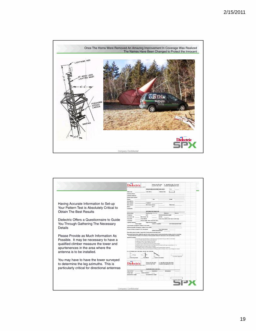
Once The Horns Were Removed An Amazing Improvement In Coverage Was RealizedThe Names Have Been Changed to Protect the Innocent
Company Confidential
Copyright@2008 SPX Corporation
Company Confidential
Having Accurate Information to Set-up Your Pattern Test is Absolutely Critical to Obtain The Best Results
Dielectric Offers a Questionnaire to Guide You Through Gathering The Necessary Details
Please Provide as Much Information As Possible. It may be necessary to have a qualified climber measure the tower and apurtenences in the area where the antenna is to be installed.
Company Confidential
Copyright@2008 SPX Corporation
Company Confidential
a e a s o be s a ed
You may have to have the tower surveyed to determine the leg azimuths. This is particularly critical for directional antennas
2/15/2011
20
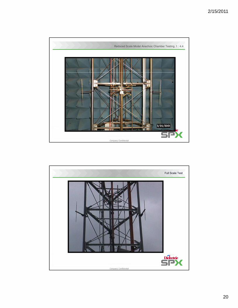
Reduced Scale Model Anechoic Chamber Testing, 1 : 4.4
Company Confidential
Copyright@2008 SPX Corporation
Company Confidential
Full Scale Test
Company Confidential
Copyright@2008 SPX Corporation
Company Confidential

2/15/2011
21
Test ModelDetails Can Make All The Difference
Conduits
Bracing
Sizes
Leg Diameters
Company Confidential
Copyright@2008 SPX Corporation
Company Confidential
Tower Width vs. Azimuth
Company Confidential
Copyright@2008 SPX Corporation
Company Confidential
18” Face 24” Face

2/15/2011
22
Tower Width vs. Azimuth
Company Confidential
Copyright@2008 SPX Corporation
Company Confidential
36” Face 48” Face
Rotation of Antenna on Tower Leg
LEFT
Company Confidential
Copyright@2008 SPX Corporation
Company Confidential
CENTER
RIGHT
2/15/2011
23
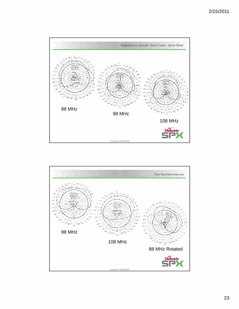
Frequency vs. Azimuth, Same Tower.. Same Offset
88 MH
Company Confidential
Copyright@2008 SPX Corporation
Company Confidential
88 MHz98 MHz
108 MHz
Face Mounted Antennas
88 MHz
Company Confidential
Copyright@2008 SPX Corporation
Company Confidential
108 MHz
88 MHz Rotated

2/15/2011
24
HD Radio™ Dielectric Interleaved Field ResultsHD Radio™ Dielectric Interleaved Field Results
Clear Channel – Chattanooga, TN
– 20 dB IBOC + Analog Waveform
Isolation > 40 dBNo sign of spectral re-growth
No Circulator!
Dielectric HDR Series Interleaved Antenna
-20 dB IBOC
(-41.4 dB)
Company Confidential
Copyright@2008 SPX Corporation
Company Confidential
Digital Tx Solid State
TAL > 20 dB
Analog Tx Solid State
TAL > 20 dB
Combined sample output of analog and digital transmitters
PAGE 47
Interleaved Arrays – Field DataInterleaved Isolation
-45
-40
-35
-30
Iso
lati
on
(d
B)
Interleaved Isolation
-35
-30
-50
103.5 103.55 103.6 103.65 103.7 103.75 103.8 103.85 103.9
Frequency (MHz)
Interleaved Isolation
-40
-35
-30
Isola
tio
n (dB
)
WQPR
KZTH
Company Confidential
Copyright@2008 SPX Corporation
Company Confidential
PAGE 48
-50
-45
-40
88.5 88.55 88.6 88.65 88.7 88.75 88.8 88.85 88.9
Frequency (MHz)
Iso
lati
on
(d
B)
-50
-45
88.3 88.35 88.4 88.45 88.5 88.55 88.6 88.65 88.7
Frequency (MHz)
WTRZ
U.S. Patents 6,914,579 6,972,731 & 7,102,589

2/15/2011
25
Interleaved Arrays – Field Data
Dual Frequency Antenna – 94.7 & 101.1 MHz KESS
KRTH
KAMP
Isolation - Analog to Digital
-33
-31
B)
Isolation - Analog to Digital
-30
-20
-10
0
atio
n (dB)
Company Confidential
Copyright@2008 SPX Corporation
Company Confidential
PAGE 49
-45
-43
-41
-39
-37
-35
88 93 98 103 108
Frequency (MHz)
Iso
lati
on
(d
B
-60
-50
-40
107.4 107.6 107.8 108 108.2 108.4
Frequency (MHz)
Isola
U.S. Patents 6,914,579 6,972,731 & 7,102,589
KESS – Isolation Verification
Analog TPO 28,000 Watts 14.47 dB
Analog Line Efficiency 71.20% (1.48 dB)
Digital Line Efficiency 61.50% (2.11 dB)
Analog - Digital Isolation (44.4 dB)
Analog Power at Digital Transmitter (33.52 dB) 1.2 Watts
Digital TPO 300 Watts (5.22 dB)
Digital VSWR 1.04:1 (34.0 dB)
Reflected Power from VSWR 0.2 Watts
Company Confidential
Copyright@2008 SPX Corporation
Company Confidential
PAGE 50
Total Reflected Power at Digital Transmitter 1.4 Watts
Spectral Re-growth into Analog at -20 dB (-10 dB) -95.4 dB (-105.4)
Spectral Regrowth into Digital at -20 dB (-10 dB) -105.4 dB (-115.4)
*Assume -6 dB for TAL on Analog Xmtr and -16 dB for TAL on Digital Xmter*
Spectral Re-growth well below -74.4 Mask Limit

2/15/2011
26
KESS – Isolation in Inclement Weather
Analog TPO 28,000 Watts 14.47 dB
Analog Line Efficiency 71.20% (1.48 dB)
Digital Line Efficiency 61.50% (2.11 dB)
Analog - Digital Isolation (35.4 dB)
Analog Power at Digital Transmitter (24.52 dB) 3.5 Watts
Digital TPO 300 Watts (5.22 dB)
Digital VSWR 1.04:1 (34.0 dB)
Reflected Power from VSWR 0.2 Watts
4 Watts
Company Confidential
Copyright@2008 SPX Corporation
Company Confidential
PAGE 51
Total Reflected Power at Digital Transmitter 3.7 Watts
Spectral Re-growth into Analog at -20 dB (-10 dB) -86.4 dB (-96.4)
Spectral Regrowth into Digital at -20 dB (-10 dB) -96.4 dB (-106.4)
*Assume -6 dB for TAL on Analog Xmtr and -16 dB for TAL on Digital Xmter*
Spectral Re-growth well below -74.4 Mask Limit
> Efficient• Eliminates the high losses associated with high level combining• Efficient use of tower space; only requires 10’ of additional aperture
> Future Proof• Interleaving accepts any elevated level of IBOC• Even if HD Radio does not gain acceptance, the broadcaster is left with a completely functional auxiliary
HD Radio™ Space Combining HD Radio™ Space Combining –– Interleaving AdvantagesInterleaving Advantages
antenna system
> Simple / Reliable• Industry proven and accepted antenna types• HD array can be interleaved within an existing analog array without affecting the current antenna system• Provides consistent coverage area for both analog and digital
> Analog/Digital - Completely separate antenna systems• If a failure occurs in an interleaved solution, either input, digital or analog can be swapped and used as an
emergency standby
> Flexibility • The concept can be applied to mixtures of feed designs or antenna type
Company Confidential
Copyright@2008 SPX Corporation
Company Confidential
• The concept can be applied to mixtures of feed designs or antenna type• Series – Series, Series – Branch, Branch – Branch, Branch – Series• M-bays and M-bays, C-bays and C-bays, M-bays and C-bays
Bottom Line….Interleaving is “Low Risk” and “Future Proof”
PAGE 52
2/15/2011
27
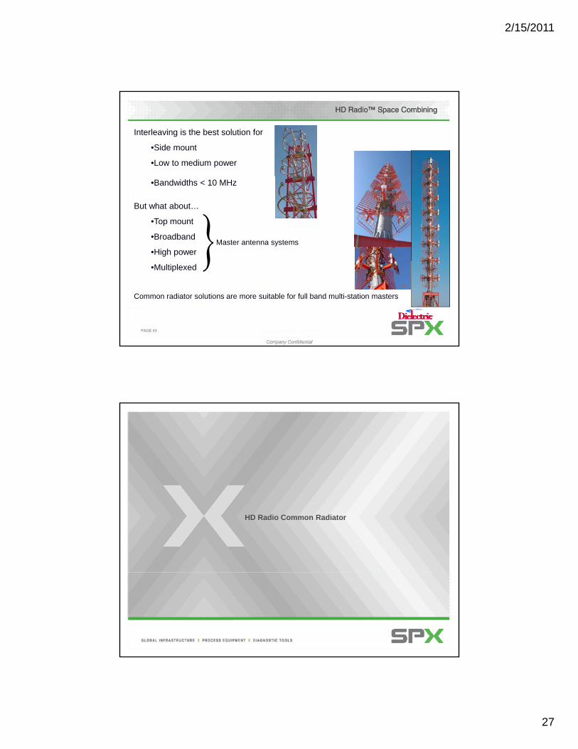
Interleaving is the best solution for
•Side mount
•Low to medium power
HD Radio™ Space CombiningHD Radio™ Space Combining
•Bandwidths < 10 MHz
But what about…
•Top mount
•Broadband
•High powerMaster antenna systems
Company Confidential
Copyright@2008 SPX Corporation
Company Confidential
PAGE 53
•Multiplexed
Common radiator solutions are more suitable for full band multi-station masters
HD Radio Common Radiator

2/15/2011
28
Common Radiator and Isolation
Factors that govern the level of isolation achievable in a common radiator
1. Cross coupling C t ll d th h
HD Radio™ Space Combining HD Radio™ Space Combining –– Common Radiator IsolationCommon Radiator Isolation
2. Mutual coupling
3. Radiator VSWR
4. Feed system VSWR Controlled through
smart design
Company Confidential
Copyright@2008 SPX Corporation
Company Confidential
PAGE 55
Cross coupling
addition at random phasesMutual coupling
HD Radio™ Space Combining HD Radio™ Space Combining –– Common Radiator Isolation BudgetCommon Radiator Isolation Budget
Expected isolation of a typical style panel antenna
Mutual coupling
Power divider VSWR
Feedlines VSWR
Radiator VSWR
Cross coupling
Feedlines
Power divider
Radiator
Source VSWR
Company Confidential
Copyright@2008 SPX Corporation
Company Confidential
PAGE 56
Analog
DigitalExpected Isolation
Cross coupling (25 dB) 1.12 0.057Mutual coupling (20 dB) 1.22 0.099Radiator impedance 1.15 0.070Feed lines/connectors 1.04 0.020Power dividers 1.05 0.024
Expected Isolation 17.1dB

2/15/2011
29
Define cross coupling and mutual coupling
Cross coupling is the inter-bay dipole to dipole coupling
HD Radio™ Space Combining HD Radio™ Space Combining –– Common Radiator IsolationCommon Radiator Isolation
dipole coupling
Mutual coupling is layer to layer coupling
Company Confidential
Copyright@2008 SPX Corporation
Company Confidential
PAGE 57
HD Radio™ Space Combining HD Radio™ Space Combining –– Common RadiatorCommon Radiator
Digital - left hand CP
•Crossed dipoles fed by a 90 degree hybrid
•Input ports to the hybrid are fed with separate analog and digital signals
Analog - right hand CP•The hybrid combines the signals and feeds the dipoles
•Systems produce an analog right hand circularly polarized signal and a digital left hand circularly polarized signal
Company Confidential
Copyright@2008 SPX Corporation
Company Confidential
PAGE 58
U.S. Patents 6,914,579 & 6,934514

2/15/2011
30
The isolation between the input ports of a hybrid coupler can only be as good as the load
reflection AND/OR the isolation between the output portsCross coupling
HD Radio™ Space Combining HD Radio™ Space Combining –– Common Radiator IsolationCommon Radiator Isolation
C
C
Isolation40
60
Isolation
Company Confidential
Copyright@2008 SPX Corporation
Company Confidential
PAGE 59
C0
20
1 1.5 2
Isolation
VSWR mismatch
Reflections from mismatches and coupling have the same effect. They degrade the isolation between the input ports
HD Radio™ Space Combining HD Radio™ Space Combining –– Common Radiator IsolationCommon Radiator Isolation
How can the isolation of a typical common radiator be improved?
The only way to achieve analog to digital isolation in a common The only way to achieve analog to digital isolation in a common radiator solution is to reduce cross coupling and mutual coupling radiator solution is to reduce cross coupling and mutual coupling and have very low VSWR in each radiator inputand have very low VSWR in each radiator input
Not an easy task
Company Confidential
Copyright@2008 SPX Corporation
Company Confidential
Not an easy task…………
PAGE 60

2/15/2011
31
TQT™ -Transverse Quadrilateral Technology
Dielectric has developed a radiator design which:
•Has very low cross coupling
•Has very low mutual coupling
HD Radio™ Space Combining HD Radio™ Space Combining –– Common Radiator TQT TechnologyCommon Radiator TQT Technology
•Excellent VSWR performance for both analog and digital inputs
Company Confidential
Copyright@2008 SPX Corporation
Company Confidential
PAGE 61
Protected by U.S. Patents 6,914,579 & 6,934514
How TQT™ Works – Elimination of Cross Coupling
Non-crossover Hybrid coupler
Company Confidential
Copyright@2008 SPX Corporation
Company Confidential
Hybrid coupler analysis applied to the TQT™ element

2/15/2011
32
TQT™ Element Driven by Loop Currents
This analysis leads to the understanding that the TQT™ radiating element is driven byloop currents as opposed to linear currents that would be found on a typical crosseddipole configuration.
Company Confidential
Copyright@2008 SPX Corporation
Company Confidential
How TQT™ Works – Minimizing Mutual Coupling
Given the loop nature of the element, loop antenna theory can be applied to understand how mutual coupling is minimized.
> VPOL propagates perpendicular to loop; in loops neutral planeO
Company Confidential
Copyright@2008 SPX Corporation
Company Confidential
• No VPOL coupling
> Faces 1 and 3 are orthogonal to HPOL; in the neutral plane• No coupling
> A potential difference can only be created between faces 2 and 4• The voltage induced between the sides is proportional to the
distance between them

2/15/2011
33
HD Radio™ Space Combining HD Radio™ Space Combining –– Common Radiator TQT TechnologyCommon Radiator TQT Technology
Expected isolation of a top / side mount TQT with a hybrid on the back of each panel
Cross coupling
Source VSWR Cross coupling (40 dB) 1.02 0.010Mutual coupling (32 dB) 1 05 0 024
Mutual coupling
Radiator VSWR Hybrid
Company Confidential
Copyright@2008 SPX Corporation
Company Confidential
PAGE 65
Mutual coupling (32 dB) 1.05 0.024Radiator impedance 1.05 0.024Feed lines/connectors 1 0.000Power dividers 1 0.000
Expected Isolation 31.1dBAnalog
DigitalExpected Isolation
VS
WR
1.08
1.12
1.16
1.2
AnalogDigital
HD Radio™ Space Combining HD Radio™ Space Combining –– Common Radiator TQT TechnologyCommon Radiator TQT Technology
Side mount TQT measured performanceR
1
1.04
88 92 96 100 104 108
30
-20
-10
0
Frequency
Isolatio
Company Confidential
Copyright@2008 SPX Corporation
Company Confidential
PAGE 66
-50
-40
-30
88 92 96 100 104 108
Frequency
on

2/15/2011
34
330
300
270 90
60
30
0
0.00.10.20.30.40.50.60.70.80.91.01.11.21.3
Black CompositeBlue HPOL
Red VPOLGreen RMS
HDFMVee
Top Mount
HD Radio™ Space Combining HD Radio™ Space Combining –– Common Radiator TQT TechnologyCommon Radiator TQT Technology
HDFMVee TQT measured performance
270
240
210180
150
120
VSWR vs. Frequency
1.1
1.15
1.2
SW
R
Isolation between analog and digital
Company Confidential
Copyright@2008 SPX Corporation
Company Confidential
1
1.05
88 93 98 103 108
Frequency (MHz)
VS
Analog Input Digital Input
Field measured isolation > 30 dB without the use of a circulator
PAGE 67
Analog Input (RHP)
Field Data from Similar Designs Field Data from Similar Designs –– St. St. Louis, MOLouis, MO
Includes 1,100 ft plus of
Transmission Line,
Power Splitter, Phasing
Loop, etc.
1.10:1 VSWR
Company Confidential
Copyright@2008 SPX Corporation
Company Confidential February 15, 2011 68
Digital Input (LHP)
1.10:1 VSWR

2/15/2011
35
Analog Input (RHP)
Field Data from Similar Designs Field Data from Similar Designs ––Portland, ORPortland, OR
Company Confidential
Copyright@2008 SPX Corporation
Company Confidential February 15, 2011 69
Includes 1,100 ft plus of Transmission
Line / Flex Line and Master Antenna
Digital Input (LHP)
Antenna LHCP
Antenna RHCP
Dielectric Antenna IsolationDielectric Antenna Isolation
•Isolation is Transmission Measurement•One TL (RHCP) to Other TL (LHCP)
Company Confidential
Copyright@2008 SPX Corporation
Company Confidential February 15, 2011 70
Does Not Include or Require Circulators
Isolation From Field Does not Include 25 dB Additional from CirculatorsInvestment Per Station for Poor Antenna Design is Over $25k Per StationDC Isolation always Shown w/o CirculatorsReoccurring Operating Costs Reduced Monthly (Power, HVAC, etc)

2/15/2011
36
HD Radio™ SummaryHD Radio™ Summary
Implementation Methods
High Level Combining Split Level Combining Common Amplification
Space Combining
Separate Antennas
•Most efficient
•Attractive at elevated IBOC levels
•Inefficient
•Not practical for elevated IBOC levels
•Coverage congruency may cause host analog interference
•Most elegant solution
•Linearity for efficiency
•Transmitter manufacturers working to improve
Company Confidential
Copyright@2008 SPX Corporation
Company Confidential
PAGE 71
Common RadiatorInterleaving
•Side mount solution < 10 MHz bandwidth
•Simple / Reliable / Flexible
•Low risk – future proof
•Full band master antenna solution
Keys to success
• High Analog Transmitter TAL
•Antenna A/D Isolation
Company Confidential
Copyright@2008 SPX Corporation
Company Confidential
PAGE 72
Questions?

2/15/2011
37
Filters and Combiner Systems
•Dibrid Coupler
•Bandpass Filters
•Branch Combiners
•Constant Impedance Combiners
•Custom RF Components and Sub systems
Company Confidential
Copyright@2008 SPX Corporation
Company Confidential
•Custom RF Components and Sub-systems
High Level High Level -- “Lossy” Combining“Lossy” Combining
10 dB Hybrid10 dB Hybrid
Analog I/P Combined O/P
“Easy”and inexpensive
Company Confidential
Copyright@2008 SPX Corporation
Company ConfidentialAll pages and images © 2007 Dielectric Communications, A unit of SPX Corporation. Information contained herein is confidential property of SPX. It is to be used solely for the purpose provided, and is not to be disclosed to others without the prior written consent of SPX.
but….
Very inefficient

2/15/2011
38
10 DB INJECTOR SWITCHER COMBINER
•SWITCHABLE ANALOG & IBOC•HIGHLY RELIABLE•LOW VSWR•LOW LOSS•COMPACT
•ON THE BENCH 43 DB ISOLATION
•IN THE FIELD•ISOLATION IS LOAD DEPENDANT
•LOSE 10% ANALOG & 90% IBOC
Operational Modes:
Analog plus Digital to antenna
Company Confidential
Copyright@2008 SPX Corporation
Company ConfidentialAll pages and images © 2007 Dielectric Communications, A unit of SPX Corporation. Information contained herein is confidential property of SPX. It is to be used solely for the purpose provided, and is not to be disclosed to others without the prior written consent of SPX.
Analog plus Digital to antenna
Analog to Antenna, Digital to Load
Analog to Load, Digital to Antenna
Analog plus Digital to Load
HDR SPLIT LEVEL™ DIBRID
•HOT SWITCHED ANALOG & ANA-IBOC•HIGHLY RELIABLE•STABLE•COMPACT•EFFICIENTC•ISOLATION= 40 DB ON BENCH•ISOLATION LIMITED BY RETURN LOSS OF SYSTEM BEYOND OUTPUT•LOSE 75% OF IBOC ONLY•GET 100% OF ANALOG
Operational Modes:
Analog plus Digital to antenna
Company Confidential
Copyright@2008 SPX Corporation
Company ConfidentialAll pages and images © 2007 Dielectric Communications, A unit of SPX Corporation. Information contained herein is confidential property of SPX. It is to be used solely for the purpose provided, and is not to be disclosed to others without the prior written consent of SPX.
Analog plus Digital to antenna
Analog to Antenna, Digital to Load
Analog to Load, Digital to Antenna
*Does Not provide Analog plus Digital to Load Option

2/15/2011
39
Split Level Combining Split Level Combining -- DibridDibrid
> Advantage: No analog power lostExample
Tx1 = Analog 28 kWTx2 = Analog 7 kW + 1.75 kW Digital (4:1 Ratio)
P 35 kW Analog + 350 W Digital (Full Power Digital)
PT ANT
PT ANT = 35 kW Analog + 350 W Digital (Full Power Digital)PT LOAD = 1.4 kW Digital
> Different modes of operationDifferent transmitter combinations
> Switchable under power
> Utilizes standard components
Company Confidential
Copyright@2008 SPX Corporation
Company ConfidentialAll pages and images © 2007 Dielectric Communications, A unit of SPX Corporation. Information contained herein is confidential property of SPX. It is to be used solely for the purpose provided, and is not to be disclosed to others without the prior written consent of SPX.
Tx2
Solid State
Analog + Digital
T ANT
100 % Analog
10% to 20% Digital
PT Load
0 % Analog
80% to 90% Digital
Depends of the power ratio of the analog transmitters
Bandpass Filters
• IBOC compatible• Stable
• Wide pass band & VSWR• Wide pass-band & VSWR bandwidth eliminate drift problems.
• Truly modular, additional sections may be bolted on in the event of requirement change. Allows stocking of modules for quick delivery.
• Retunable• Fixed iris• Invar probe adjuster• Efficient
Company Confidential
Copyright@2008 SPX Corporation
Company Confidential
• Low loss filter design rarely requires forced air cooling

2/15/2011
40
Filter Response for 3, 4 & 5 Stage Filters
2.21062 108
22
17
trans f( )
refl f p
freq .850freq 1.0
30
20
10
0Filter Response 2.448807 10
4
24
30trans f( )
refl f p
freq .850freq 1.0
30
20
10
0Filter Response
ns, R
efl C
oeff
60
Plotcent 2Plotcent 2 f f p100.9 101.3 101.7 102.1 102.5 102.9 103.3 103.7 104.1 104.5 104.9
60
50
40
Frequency
60
Plotcent 2Plotcent 2 f f p100.9 101.3 101.7 102.1 102.5 102.9 103.3 103.7 104.1 104.5 104.9
60
50
40
Frequency
Tra
n
2.302513 104
trans f( )
freq .850freq 1.0
20
10
0Filter Response
Coe
ff
Company Confidential
Copyright@2008 SPX Corporation
Company Confidential
60
47
39
refl f p
Plotcent 2Plotcent 2 f f p100.9 101.3 101.7 102.1 102.5 102.9 103.3 103.7 104.1 104.5 104.9
60
50
40
30
Frequency
Tra
ns, R
efl
Branch Combiner
• Approximately 1/3 the cost of a constant impedance combiner
• For systems of up to 3 stations• Frequency Spacing >1.2 MHz• Minimum floor-space required, can be
configured in a number of variations to fit in cramped spaces
• Short lead time availability due to modular design
• Filters fit through standard single door
Company Confidential
Copyright@2008 SPX Corporation
Company Confidential

2/15/2011
41
Typical Constant Impedance Combiner
•The Most Efficient In the Industry
•Best Frequency Response in the IndustryIndustry
•Expandable Virtually Any Number of Stations
•Stable-Fixed Iris Design
•The Most Reliable, Never Had a in-field module Failure
•Highest Power Systems In Service
•Temperature Stable Installed
Company Confidential
Copyright@2008 SPX Corporation
Company Confidential
Temperature Stable, Installed Systems with Individual Inputs of as much as 44 kW Convection Cooled.
IBOC compatible for low loss insertion
Manifold Combiners
• Uses Standard Bandpass filters
• Smaller footprint than CIF Units
• For up to 10 stations
• Excellent Electrical Performance• Excellent Electrical Performance
• Economical
• Patented Technology
Company Confidential
Copyright@2008 SPX Corporation
Company Confidential

2/15/2011
42
Patents Dual input / Interleaved Antennas
Company Confidential
Copyright@2008 SPX Corporation
Company Confidential
PAGE 83
Interleaved Patents
Company Confidential
Copyright@2008 SPX Corporation
Company Confidential
PAGE 84