conical diffraction effect in optical and x-ray smith
TRANSCRIPT
Conical diffraction effect in optical and x-ray Smith-Purcell radiation
D. Yu. Sergeeva,* A. A. Tishchenko,† and M. N. StrikhanovNational Research Nuclear University “MEPhI”, Kashirskoe sh. 31, 115409 Moscow, Russia
(Received 4 March 2014; revised manuscript received 12 December 2014; published 8 May 2015)
Smith-Purcell radiation is a well-known phenomenon, which provides a noninvasive scheme fordiagnostics of charged particle beams and is used as an effective source of electromagnetic waves, e.g., inthe orotron, the free electron laser, etc. In this paper we develop the theory of Smith-Purcell radiation (SPR)for the little-investigated case of arbitrary angles between the charged particle trajectories and the rulings ofa grating. The effect of conical diffraction arising here changes drastically the space distribution of theradiation. By contrast to the only existing approach, described by Haeberle et al. [Phys. Rev. E 55, 4675(1997)], which requires difficult numerical calculations, we give a fully analytic theory of SPR. Also, in thispaper we present for the first time the theory of x-ray Smith-Purcell radiation. Evanescent waves on thesurface are shown to lead to strong enhancement of Smith-Purcell radiation, through a resonant mechanism.The results are important for the description of real divergent high-brightness beams and for thedevelopment of novel noninvasive diagnostic schemes based on the Smith-Purcell effect.
DOI: 10.1103/PhysRevSTAB.18.052801 PACS numbers: 42.25.Fx, 41.60.-m, 78.70.-g
I. INTRODUCTION
There are two main ways for charged particles to radiate:first, when the particle changes its velocity in an externalfield. This happens, for example, in Roentgen tubes(bremsstrahlung), in free electron lasers based on undulatorradiation, and so on.The second type of radiation is called polarization
radiation and arises when a moving charge acts uponmatter by its Coulomb field, and the matter polarized bythis dynamically changing field becomes a source ofradiation. The charged particle itself can move uniformlyand nevertheless generate electromagnetic radiation. Herewe talk not only about the widely known Cherenkov andtransition radiations, but also about diffraction radiation(DR) (arising when charge moves near a target), aboutSmith-Purcell radiation (SPR), a special case of DR fortargets with periodical surface [1,2], and about parametricx-ray radiation (x-ray radiation of a charged particlemoving in a crystal with constant velocity: see, e.g.,[3]). Polarization-type interactions of particles withmatter also can be a good source of electromagneticradiation [3–5], including free electron lasers based onSPR [6], but is especially useful for beam diagnostics [2,7].DR and SPR occupy a special place among the kinds of
polarization radiation. They occur when the trajectory of acharged particle is out of the target and the radiation
process is not followed by direct scattering of the particleson the target material. In this case the beam of particles isnot disturbed and therefore DR and SPR can providenoninvasive diagnostics of bunches [2,8]. SPR was thesubject of investigation for many researchers, starting fromthe original article by Smith and Purcell in 1953 [1]. Thetheory and applications of SPR are described in mono-graphs [2,3,9]. However, the general theory of SPR has notbeen created yet and at present there exist a number ofdifferent approaches, which sometimes are in agreementand sometimes contradict each other. The principalapproaches were developed by: (i) van den Berg ([10]:seminumerical, demands difficult numerical calculations);(ii) Shestopalov ([9]: very complicated mathematically,suitable for nonrelativistic beams mainly); (iii) Brownell,Doucas and others ([11]: physically clear and simple, validmainly for ideally conductive gratings); (iv) Potylitsyn([2,12], based on results of Kazantsev and Surdutovichfor DR [13], only for ideally conductive gratings);(v) Karlovets ([14], the most general theory at present,valid for arbitrary dielectric properties of a target; however,it requires further development and comparison withexperimental data).This short characterization of the methods expresses only
our opinion and does not pretend to be an ultimate truth.For oblique incidence, i.e., at arbitrary angle between
particle trajectory and rulings direction, none of the resultsmentioned above are valid.Haeberle with coauthors [15] constructed the theory of
SPR for the case of oblique incidence as a development ofthe van den Berg approach, (i) which is very good fornonrelativistic electrons, (ii) which for relativistic electronssometimes is in good agreement but sometimes disagreeswith experiment (see [16] and the discussion in Sec. VA),
*[email protected]†[email protected]
Published by the American Physical Society under the terms ofthe Creative Commons Attribution 3.0 License. Further distri-bution of this work must maintain attribution to the author(s) andthe published article’s title, journal citation, and DOI.
PHYSICAL REVIEW SPECIAL TOPICS - ACCELERATORS AND BEAMS 18, 052801 (2015)
1098-4402=15=18(5)=052801(13) 052801-1 Published by the American Physical Society

(iii) whose validity in EUV and x-ray range has not beeninvestigated, (iv) and which demands difficult numericalcalculations.In this paper we construct a fully analytical theory of
SPR for the case of arbitrary angle between charged particletrajectory and the rulings, from nonrelativistic up to ultra-relativistic particles: (i) in UV and x-ray range, proceedingfrom the theory of UV and x-ray diffraction radiationcreated in our previous papers (see [17–19] or in moredetail Chapter 4 in [2] and for the bunch of particles in[20,21]), (ii) in optics and THz, proceeding from the resultsfor DR of Potylitsyna-Kube and Artru [22], who managedto generalize the theory of Kazantsev and Surdutovich [13].Why and when can the case of oblique incidence be of
interest?The most important case seems to be that of divergent
beams. Coulomb interaction in a beam of moving ultra-relativistic electrons in transversal directions is screened bythe magnetic force, and the closer velocity of the electronsto the speed of light, the stronger this suppression is. Thiseffect leads to a weakening of the divergence effects,because the divergence of the beam is caused by theCoulomb repulsion of electrons. Nevertheless, in practicethe role of divergence is pronounced in some realistic cases:(a) nonrelativistic beams; (b) moderately relativistic ener-gies for high-brightness beams having small transversedimensions (compact accelerators for such ranges ofenergies are now coming into use as effective x-ray andTHz sources in security, industry, medicine etc.); (c) ultra-relativistic high-brightness beams, for example, originatingfrom laser-plasma sources [24]; (d) ultrarelativistic superhigh-brightness beams for proposed future facilities likeILC, where the size of focal spot is expected to beabout 8 nm.In all these cases conservation of phase volume
(Liouville’s theorem) results in increasing the divergence,which should be taken into account in a correct theoreticaldescription.The second situation when oblique incidence can play a
vital part arises in (e) the case of a few directions ofperiodicity, as happens in periodical structures like 2D and
3D photonic crystals [5,23]. The charged particle moving,e.g., along a 2D or 3D photonic crystal, inside or outside,will produce a radiation distribution of which should bestrongly influenced by the conical diffraction.
II. QUALITATIVE PICTURE OF RADIATION
In this section we shall demonstrate the analogy betweenSmith-Purcell radiation and reflection of light from agrating.The main features of the process of the light reflection
from a diffraction grating can be derived from conserva-tion laws.Photons of light with the wave vector k0 are scattered on
some periodical structure (which hereafter we call adiffraction grating, or just a grating) with the period d inthe x-direction and with rulings along the axis y, andbecomes the photons of reflected light with the wave vectork, see Fig. 1(a). This process should satisfy the conserva-tion laws:
k0y ¼ ky;
k0x ¼ kx þ 2πm=d; m ¼ 0;�1;�2;…;
k0 ¼ k; ð1Þ
where m is a diffraction order. The first line expresses theconservation of momentum along the direction of mediumhomogeneity—axis y; the second line states quantifiedtransfer of the momenta along the direction of theperiodicity—axis x; and the third line implies energyconservation. In the case of d → ∞ the first and secondexpressions give us the usual Snell’s law. As dielectricproperties of the medium where the light is reflected to arenot of importance (e.g., one may think that it is air), weput k0 ¼ k ¼ ω=c.Taking into account the relation k ¼ ðω=cÞr=r between
the vector k and the radius vector of the point ofobservation r ¼ ðx; y; zÞ, from the first and third formulasof Eqs. (1) one can obtain the canonical equation for a conewith the main axis y:
x
y
a d
k
v
q
e
h b
x
y
a d
kk0
(b)(a)zz
FIG. 1. (a) Reflection of light from a grating. (b) Radiation of a charged particle as a reflection of its own (Coulomb) field from thegrating. Velocity of the charged particle is v ¼ ðvx; vy; 0Þ, e is its charge, the size of a single strip is ða;∞; bÞ, the grating period is d, h isthe impact parameter, i.e., the shortest distance between the grating surface and the particle trajectory; k0 is the wave vector of a photonof incident light, k is the wave vector of a photon of reflected light, q is the momentum of virtual photons of the particle Coulomb field.
SERGEEVA, TISHCHENKO, AND STRIKHANOV Phys. Rev. ST Accel. Beams 18, 052801 (2015)
052801-2

x2
1 − n20yþ z2
1 − n20y− y2
n20y¼ 0; ð2Þ
where n0 ¼ k0=k0. The reflected light is distributed overthe conical surface, so that each diffraction order m isrepresented by the line on its surface, see Fig. 2(a). In casek0y ¼ 0 the cone is reduced to a plane, see Fig. 2(b). Thephenomenon of conical diffraction is known in optics[25–27].Now we consider another process—radiation of a
charged particle moving at some distance above the grating,see Fig. 1(b). We expand the Coulomb field E0ðr; tÞ intoFourier integral
E0ðr; tÞ ¼Z
d3rð2πÞ3
Zdt2π
e−iq·reiωtE0ðq;ωÞ: ð3Þ
For a charge e moving with the constant velocity v ¼ðvx; vy; 0Þ at the distance h (impact parameter) above theplane z ¼ 0 we have
E0ðq;ωÞ ¼ − ie2π2
q − vω=c2
q2 − k2e−hρδðω − q · vÞ: ð4Þ
Considering reflection of a plane wave (Fourier compo-nent) expð−iq · rÞ from the grating with the period d in thex-direction one can write the conservation laws as inEq. (1):
qy ¼ ky;
qx ¼ kx þ 2πm=d; m ¼ 1; 2;…;
q ¼ k: ð5Þ
The vector q in Eq. (5) is unknown, and besides theseequations do not contain the characteristics of the chargedparticle. So, one should redefine this system using onemore equation, namely,
ω ¼ q · v; ð6Þ
which comes from the delta function in Eq. (4). Noting that
qz ¼ffiffiffiffiffiffiffiffiffiffiffiffiffiffiffiffiffiffiffiffiffiffiffiffiffiq2 − q2x − q2y
q, from Eqs. (5) and (6) one can get
qz ¼ iρ; ρ ¼ffiffiffiffiffiffiffiffiffiffiffiffiffiffiffiffiffiffiffiffiffiffiffiffiffiffiffiffiffiffiffiffiffiffiffiffiffiffiffiffiffiffiffiffiffiffiffiffiffiffiffiffiffiffiffiffiffiffiffiffi�ω − kyvy
vx
�2
þ ðkyÞ2 −�ω
c
�2
s: ð7Þ
Exponential decreasing of the Coulomb field of the particlewith rise of impact-parameter h results in the same decreas-ing of the radiation filed generated by the field from Eq. (4),which is a characteristic feature of Smith-Purcell radiation.The radiation is maximal when ρ is minimal:
ρmin ¼ω
cβγ; ð8Þ
which occurs at
ky ¼ω
c
βyβ2
; ð9Þ
where β ¼ v=c. Using the first and second expressions fromEq. (5) we can rewrite Eq. (6) in the form
ω ¼ vxðkx þ 2πm=dÞ þ vyky: ð10Þ
This is Smith-Purcell dispersion relation in its general form;it interlinks the direction of observation n ¼ k=k, wave-length λ ¼ 2πc=ω, velocity v and the period of a grating d.For vy ¼ 0 Eq. (10) gives the well-known relation
obtained by Smith and Purcell [1]:
1
β− nx ¼
λ
dm; m ¼ 1; 2;…: ð11Þ
One can see from Eq. (9) that ky ¼ 0 if vy ¼ 0, andtherefore a maximum of radiation is in the plane y ¼ 0, seeFig. 2(b).With the help of Eq. (9), as it was in the case with light
reflection, we obtain the equation of a cone:
x2
1 − β2y=β4þ z2
1 − β2y=β4− y2
β2y=β4¼ 0: ð12Þ
This equation resembles Eq. (2) with the only difference:characteristics of “incident light” are defined by propertiesof the charged particle, so that βy=β2 plays the role of n0y.So, the spatial distribution of Smith-Purcell radiation at
oblique incidence (βy ≠ 0) is close to that for the conicaldiffraction of light: in accordance with Eqs. (10) and (12)the radiation is distributed over the conical surface [givenby Eq. (12)] as separate peaks with different ordersm ¼ 1; 2;…. This qualitative analysis shows the principal
FIG. 2. (a) Conical diffraction at the reflection of monochro-matic light from a grating. Separated lines on the conical surfacerefer to different diffraction orders m. (b) Conical diffraction:reducing the cone to a plane in case of k0y ¼ 0 (for lightreflection) or α ¼ 0 (for radiation). The angle between velocityv and axis x is α.
CONICAL DIFFRACTION EFFECT IN OPTICAL … Phys. Rev. ST Accel. Beams 18, 052801 (2015)
052801-3

features of radiation, but is insufficient to catch alldifferences between SPR and conical diffraction of light.Below we shall draw analytical expressions and thenanalyze the conical diffraction effect in Smith-Purcellradiation in more detail.
III. X-RAY SMITH-PURCELL RADIATION
In this section we construct the theory of Smith-Purcellradiation at frequencies
ω ≫ ωp: ð13Þ
Here ωp is the plasma frequency, which usually has valuesabout 20–30 eV [28].In practice, inequality
ω ≥ 3ωp ð14Þ
is enough. Therefore, this approach works for thewavelengths
λ ≤ 2π66 nmωpðeVÞ
ð15Þ
where ωp is taken in electron-volts and λ is measured innanometers. For example, for ωp ¼ 24; 4 eV (Mylar, [28])we have λ ≤ 17 nm, for ωp ¼ 13; 8 eV (lithium, [28])λ ≤ 30 nm. Hereafter talking of EUV/x-ray range we shallmean frequencies satisfying Eq. (13) or (14).We discussed in our previous article [17] that, construct-
ing the correct theory of DR and SPR, it is appropriate touse the method applied by Durand [29] for calculation ofx-ray transition radiation and based (i) on consideration ofpropagation of the radiation inside a medium and (ii) onseparate analysis of the process of refraction at the surface.Indeed, the refraction was neglected in [29]. As we provedlater, this is correct only when we deal with one chargedparticle and simple interface; for the beams or for periodicstructures the refraction of radiation at the surface of thetarget should be taken into account. The theory of x-ray DRwas developed by this method in the papers [2,17–19,30]for the single-particle case, and in papers [20,31] forbunches of charged particles; for optical range thisapproach was developed in papers [14,32,33].For x-ray region the dielectric function of a medium εðωÞ
can be written as
εðωÞ ¼ 1þ χ0ðωÞ þ iχ00ðωÞ;χ0ðωÞ ¼ −ω2
p=ω2: ð16Þ
For the sake of simplicity we shall neglect absorption, i.e.,take χ00 ≪ jχ0ðωÞj below; the expansion of the theory ispossible as in paper [19], where x-ray Cherenkov radiationin conditions of diffraction radiation (i.e., when the
trajectory of a particle does not cross the target) wasinvestigated. Note that in region ω ≫ ωp the value ofεðωÞ is close to the unity, and therefore any models dealingwith ideally conducting targets [15,34] are not applicablefor describing of UV and x-ray Smith-Purcell and diffrac-tion radiation.Let the charge e move with the constant velocity v ¼
ðvx; vy; 0Þ at a distance h from the target surface (impactparameter)—see Fig. 1(b). The target is a grating consistingof N strips with period d and vacuum between strips (air inpractice). The size of a strip is ða;∞; bÞ.The Coulomb field of the charged particle decreases with
increase in impact-parameter h in the direction to the targetsurface and the attenuation distance is γβλ=2π—seeEqs. (4) and (5), γ ¼ E=Mc2 is the Lorenz factor whichequals the particle energy E divided by the energy of aparticle at rest Mc2.Thus, it is easy to estimate the minimal energy of
electrons for which the radiation is intensive enough tobe observed in the frequency range ω ≫ ωp:
E > Emin ¼ 2πh=βλðMeVÞ: ð17Þ
Estimating the minimal frequency as ω ¼ 3ωp ¼ 78.3 eV(beryllium [28]), which corresponds to the wavelengthλmax ¼ 15.7 nm, we obtain
E > ðh μmÞð4 × 10² MeVÞ; ð18Þ
where h is measured in micrometers, E in megaelectron-volts. The value of impact-parameter h is bounded frombelow by the beam size. Usually the transversal size ofultrarelativistic beams is of the order of 10 μm and less.Estimating the minimal value of h being about 10 μm, onecan see that the energy of electrons E should exceed 4 GeVin order to DR and SPR in EUV and x-ray range would beappreciable.The Coulomb field of a moving charged particle pro-
duces dynamic polarization currents in medium. This leadsto arising of the radiation determined by Fourier image ofthe current density jðr;ωÞ:
jðr;ωÞ ¼ ω
4πi½εðωÞ − 1�E0ðr;ωÞ: ð19Þ
The Coulomb field of moving charge in vacuum E0ðr;ωÞcan be found from Eqs. (3) and (4). Note, we take theexpression for the Coulomb field in vacuum—to take it inform including contribution of polarization of mediumwould be incorrect, see the discussion in Chapter 4 ofmonograph [2].The radiation field is determined by current density as
E0ðr;ωÞ¼ iωc2
eik0r
r
�n0×n0×
ZV
d3rjðr;ωÞe−ik0·r�; ð20Þ
SERGEEVA, TISHCHENKO, AND STRIKHANOV Phys. Rev. ST Accel. Beams 18, 052801 (2015)
052801-4
where it is integrated over the region of existence ofpolarization currents, i.e., over the target volume V;k0 ¼ n0 ffiffiffiffiffiffiffiffiffiffi
εðωÞpω=c is the wave vector inside the medium
[2]. The prime means that a variable is taken inside thematter.Equations (19), (20) and (4) permit one to calculate the
radiation field inside the medium:
E0ðr;ωÞ ¼ − eik0r
re4π
εðωÞ − 1
vxe−ρ0h ω
2
c2ð1 − e−bρ0þik0zbÞ
×
�n0 × n0 ×
�A0
ρ0− iez
��
×1
ρ0 − ik0z
XNs¼1
�eiφ
0sd eiφ0a − 1
iφ0
�: ð21Þ
Here
A0 ¼ ω − k0yvyvx
ex þ k0yey − vω
c2;
φ0 ¼ ðω − k0xvx − k0yvyÞ=vx;
ρ02 ¼�ω − k0yvy
vx
�2
þ ðk0yÞ2 −�ω
c
�2
: ð22Þ
Generally speaking, the radiation can be refracted andreflected at the upper and forward facets (sides). In thefrequency region ω ≫ ωp one can neglect the reflectiondealing with a single particle [17–19,29]. However, wheninterference and coherence phenomena can take place, theweak effects can be accumulated, and taking the refractioninto account is important [20]. As we consider the radiationfrom a grating, i.e., periodical structure, the interferenceoccurs, and refraction at the facets ought to be taken intoaccount. We consider the situation when polarizationcurrents are produced in a thin layer near the upper facetof the target. When
n0z ≫ n0xb�
a;
b� ¼ min
�γβλ
2π− h; b
�; ð23Þ
where b� is the thickness of effectively excited andradiating part of the target, then the radiation goes out invacuum only through the upper facet.If Eq. (23) is not satisfied, then results will be correct
only qualitatively; to obtain more accurate results oneneeds to take into account the refraction of the radiationat the forward facet. The case when radiation goes outthrough both upper and forward facets was analyzedin [30].Applying the law of refraction for the upper facet we get
the connection between the unit wave vector in the mattern0 and the unit wave vector in the vacuum n in the form
ffiffiffiffiffiffiffiffiffiffiεðωÞ
pn0 ¼
nx; ny;
ffiffiffiffiffiffiffiffiffiffiffiffiffiffiffiffiffiffiffiffiffiffiffiffiffiffiffiffiεðωÞ − 1þ n2z
q : ð24Þ
We would like to stress that at
nminz ¼
ffiffiffiffiffiffiffiffiffiffiffiffiffiffiffiffiffiffi1 − εðωÞ
pð25Þ
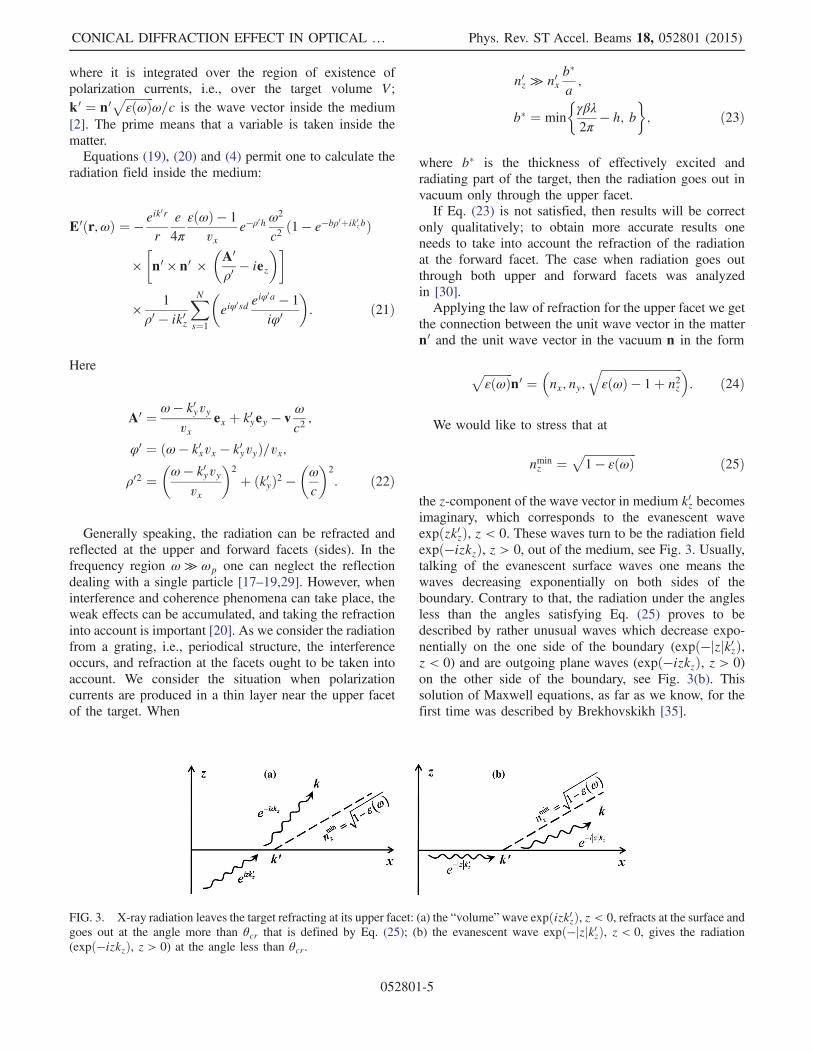
the z-component of the wave vector in medium k0z becomesimaginary, which corresponds to the evanescent waveexpðzk0zÞ, z < 0. These waves turn to be the radiation fieldexpð−izkzÞ, z > 0, out of the medium, see Fig. 3. Usually,talking of the evanescent surface waves one means thewaves decreasing exponentially on both sides of theboundary. Contrary to that, the radiation under the anglesless than the angles satisfying Eq. (25) proves to bedescribed by rather unusual waves which decrease expo-nentially on the one side of the boundary (expð−jzjk0zÞ,z < 0) and are outgoing plane waves (expð−izkzÞ, z > 0)on the other side of the boundary, see Fig. 3(b). Thissolution of Maxwell equations, as far as we know, for thefirst time was described by Brekhovskikh [35].
FIG. 3. X-ray radiation leaves the target refracting at its upper facet: (a) the “volume”wave expðizk0zÞ, z < 0, refracts at the surface andgoes out at the angle more than θcr that is defined by Eq. (25); (b) the evanescent wave expð−jzjk0zÞ, z < 0, gives the radiation(expð−izkzÞ, z > 0) at the angle less than θcr.
CONICAL DIFFRACTION EFFECT IN OPTICAL … Phys. Rev. ST Accel. Beams 18, 052801 (2015)
052801-5

So, the radiation field outside the medium has the form
Eðr;ωÞ ¼− e4π
εðωÞ− 1
vxe−ρhω
2
c2eikr
rn0×n0× ðA=ρ− iezÞρ− iωc
ffiffiffiffiffiffiffiffiffiffiffiffiffiffiffiffiffiffiffiffiffiffiffiffiffiffiffiεðωÞ− 1þn2z
p×
�1− exp
�−bρþ ib
ω
c
ffiffiffiffiffiffiffiffiffiffiffiffiffiffiffiffiffiffiffiffiffiffiffiffiffiffiffiεðωÞ− 1þn2z
q ��
×eiφa− 1
iφ
XNs¼1
eiφsd: ð26Þ
Here
φ ¼ ω
c1
βxð1 − nxβx − nyβyÞ;
ρ ¼ ω
cβγ
ffiffiffiffiffiffiffiffiffiffiffiffiffiffiffiffiffiffiffiffiffiffiffiffiffiffiffiffiffiffiffiffiffiffiffiffiffiffiffiffiffiffiffiffi1þ γ2β−2x ðnyβ2 − βyÞ2
q;
A ¼ ω
βxcð1 − nyβy − β2x; nyβx − βxβy; 0Þ; ð27Þ
and n0 is taken from the right part of Eq. (24).Using Eq. (26) it is easy to find the energy of Smith-
Purcell radiation emitted per unit solid angle and frequencyin EUV/x-ray range:
d2Eðn;ωÞdΩdℏω
¼ d2E0ðn;ωÞdΩdℏω
4sin2�aφ2
�sin2ðNdφ=2Þsin2ðdφ=2Þ : ð28Þ
Here expression
d2E0ðn;ωÞdΩdℏω
¼ 1
137
�εðωÞ − 1
4πβxφ
�2
e−2ρhFbω4
c4
×j½n0 × n0 × ðA=ρ − iezÞ�j2
jρ − iðω=cÞffiffiffiffiffiffiffiffiffiffiffiffiffiffiffiffiffiffiffiffiffiffiffiffiffiffiffiffiεðωÞ − 1þ n2z
pj2 ð29Þ
describes the radiation from one strip (slab) with sizesða;∞; bÞ, factor Fb describes the dependence of radiationon the strip thickness:
Fb ¼����1 − exp
�−bρþ ib
ω
c
ffiffiffiffiffiffiffiffiffiffiffiffiffiffiffiffiffiffiffiffiffiffiffiffiffiffiffiffiεðωÞ − 1þ n2z
q �����2: ð30Þ
Equation (28) in the particular case of N ¼ 1 coincideswith the results of paper [17], when corrections of the order
of ðωp=ωÞ2 ≪ 1 and γ−2 ≪ 1 are neglected. In the case ofβy ¼ 0 (α ¼ 0) the results are similar to those reported in[36]. Close results for x-ray SPR at α ¼ 0 and small anglesof radiation were obtained in [37].
IV. SMITH-PURCELL RADIATION ATOPTICAL AND LOWER FREQUENCIES
Now we shall consider the radiation from N thin strips(thickness b → 0) for those very configuration as in Sec. III[see Figs. 1(b) and 2(a)], but at the optical and lowerfrequencies. We shall proceed from the results ofPotylitsyna-Kube and Artru [22], who managed to general-ize the well-known theory of diffraction radiation forinfinitely thin and ideally conducting half-plane—themodel created by Kazantsev and Surdutovich [13] usingthe Wiener-Hopf technique.The expression for the field of the radiation EHðr;ωÞ
from an ideally conducting half-plane can be obtained fromthe results of [22]. Let us consider the target as a grating ofN strips of width a, see Fig. 4(a). Each strip has two edges,therefore the resulting radiation can be obtained fromsimple geometrical consideration. The phase differenceΔa ¼ kΔr − ωΔt of the waves generated by each edge ofthe strip is written in the form
Δa ¼ω
caβx
ðβn − 1Þ: ð31Þ
The field of radiation from a single strip in case a ≫ λ is
Eaðr;ωÞ ¼ EHðr;ωÞ −EHðr;ωÞ expðiΔaÞ: ð32Þ
Terms in Eq. (32) have opposite signs because for the firstedge the particle flies coming to the strip, and for thesecond edge it flies getting away.Writing the analogous expressions for each of N strips
ΔN ¼ ω
cdβx
ðβn − 1Þ; ð33Þ
ENðr;ωÞ ¼ Eaðr;ωÞ þ Eaðr;ωÞ expðiΔNÞ þ � � �þ Eaðr;ωÞ exp½iðN − 1ÞΔN �; ð34Þ
FIG. 4. Scheme of generating of optical SPR.
SERGEEVA, TISHCHENKO, AND STRIKHANOV Phys. Rev. ST Accel. Beams 18, 052801 (2015)
052801-6

we can find the expression for distribution of emitted energy of SPR in the form of Eq. (28), where d2E0ðn;ωÞ=ðdΩdℏωÞ isfound from [22] after adapting it to the coordinate system taken in our paper:
d2Eðn;ωÞdℏωdΩ
¼ 1
137
1
4π2βxð1 − βynyÞffiffiffiffiffiffiffiffiffiffiffiffiffi
1 − n2yq �
ω
cβx
�4 1
ρ2φ2expð−2ρhÞ
×
264ð1 − 2βyny − β2x þ β2n2yÞ
0B@1þ
βx
ffiffiffiffiffiffiffiffiffiffiffiffiffi1 − n2y
q1 − βyny
1CA0B@1 − nxffiffiffiffiffiffiffiffiffiffiffiffiffi
1 − n2yq
1CA
þ ðβy − nyÞ20B@1 − βx
ffiffiffiffiffiffiffiffiffiffiffiffiffi1 − n2y
q1 − βyny
1CA0B@1þ nxffiffiffiffiffiffiffiffiffiffiffiffiffi
1 − n2yq
1CA3754sin2�aφ
2
�sin2ðNdφ=2Þsin2ðdφ=2Þ : ð35Þ
Here ρ¼ ωcβγ
ffiffiffiffiffiffiffiffiffiffiffiffiffiffiffiffiffiffiffiffiffiffiffiffiffiffiffiffiffiffiffiffiffiffiffiffiffiffiffiffiffiffiffi1þ γ2β−2x ðnyβ2− βyÞ2
q, φ ¼ ω
c1βxð1 − nxβx−
nyβyÞ are the same as in the x-ray range. Equation (35) inthe case of α ¼ 0 coincides with the expression obtainedearlier [2], and for N ¼ 1 coincides with the results ofpapers [17,12].
V. ANALYSIS
A. Spatial distribution of Smith-Purcell radiation
According to Eqs. (28) and (35) the distribution of theradiation both in x-ray and optical regions is proportional tothe exponent and the ratio of squared sines:
d2Eðn;ωÞdΩdℏω
∝sin2ðNdφ=2Þsin2ðdφ=2Þ expð−2ρhÞ: ð36Þ
These are two multipliers that define the surface ofmaximal SPR. When the target consists of many strips,i.e., N ≫ 1, the ratio of squared sines goes to the sum ofdelta functions:
sin2ðNdφ=2Þsin2ðdφ=2Þ →
N≫1
2πNXm
δðdφ − 2πmÞ: ð37Þ
The Smith-Purcell dispersion relation in the case of obliqueincidence follows from Eqs. (37) and (27):
dλ
1
βxð1 − nxβx − nyβyÞ ¼ m; m ¼ 1; 2;…: ð38Þ
Designating the angle between the velocity and the direc-tion of radiation as χ we write Eq. (38) in the form
dcos α
ðβ−1 − cos χÞ ¼ λm; m ¼ 1; 2;…: ð39Þ
Index m is the diffraction order. Equation (38) coincideswith Eq. (10) obtained with the help of conservation laws.
Equation (39) was obtained also in works [15,38]. In[38], the authors got it, but did not analyze. In [15] the effectof conical diffraction in SPR was considered for lowfrequency range and for nonrelativistic particles only. Wewould like to notice that the model of van den Berg [10]followed by the authors of paper [15] can be applied also forthe relativistic case, but with variable success. For example,see the comparison with experimental data for energies ofelectrons of 855 MeV in the paper of Kube et al. [16],where, comparing theory and experiment, in Fig. 11 onecan see rather good agreement (deep grating), in Fig. 10 fordeep grating the agreement is satisfactory for λ ¼ 360 nmand bad for λ ¼ 546 nm (discrepancy in ten times), and inFig. 12 contradiction between theory and experiment forshallow grating (discrepancy in hundred times). In paper[16] another problem of the van den Berg theory was alsomentioned: it requires extensive numerical calculationsuntil finally the numerical solution of the integral equationsconverges, which is especially hard in the case λ ≪ d (seealso [39]). The interested reader can find in paper [40] thecomparison the theories of van den Berg [10], Brownell,Doucas and others [11], and Potylitsyn [2,12]; see also theshort discussion in the Introduction.The second multiplier expð−2ρhÞ in Eq. (36) has
maximum when ρ ¼ ρmin, which gives the condition
nmaxy ¼ βy=β2: ð40Þ
It follows from Eqs. (38) and (40) that the Smith-Purcellpeaks, corresponding to different values of the spectralorder m, in the case of oblique incidence are distributedover the surface of the cone, centered along the axis y (i.e.,the axis of rulings direction), like it was shown in Sec. II.Choosing βx ¼ β cos α, βy ¼ β sin α we find the equationof the cone, agreeing with Eq. (12):
x2
1 − sin2αβ2
þ z2
1 − sin2αβ2
− y2
sin2αβ2
¼ 0: ð41Þ
CONICAL DIFFRACTION EFFECT IN OPTICAL … Phys. Rev. ST Accel. Beams 18, 052801 (2015)
052801-7

From Eqs. (38) and (40) we can find the angles describingpositions of peaks on the cone. Assuming θ is polar angleand ϕ is the azimuthal angle as it is shown in Fig. 5,
nx ¼ sin θ cosϕ;
ny ¼ cos θ;
nz ¼ sin θ sinϕ; ð42Þ
one can obtain a set of couples fθm;ϕmg—the anglesdefining the direction of maximal radiation correspondingto the mth diffraction order:
( θm ¼ arccosðβ−1 sin αÞϕm ¼ arccos
1β
cos α−λmβ=dffiffiffiffiffiffiffiffiffiffiffiffiffiffiffiffiffiffiffiffi1−ðβ−1 sin αÞ2
p ; m ¼ 1; 2;…: ð43Þ
It follows from Eqs. (43) and (42) that for orders
m ≥dλ
cos αβ
ð44Þ
the radiation is distributed in half-space with negative valueof x. Diffraction and transition radiations are usuallythought to be concentrated near the direction of the chargedparticle velocity. The radiation propagating in the directionof mirror reflection of particle velocity relative to therulings direction is called “backward radiation”—backwardTR or backward DR. As opposed to them, SPR representsthe peaks (rays) of radiation distributed in space over theconical surface. Let us find a condition of existing of a SPRpeak in the direction of mirror reflection relative to therulings direction for each SPR peak. First, we write thedispersion relation Eq. (38) for the peak of SPR ofm1 orderin the “forward” direction, i.e., for nx > 0; and for the peakof SPR of m2 order in the direction of mirror reflection tom1, i.e., for nx < 0. Summing up these two equations wefind
2dλ
1
βxð1 − nyβyÞ ¼ m1 þm2: ð45Þ
Designating m2 þm1 ¼ l, l ¼ 2; 3;…, with help of thecondition for the cone ny ¼ βy=β2 one can see that in thecase of
dλ¼ β
2 cos αl; l ¼ 2; 3… ð46Þ
there is a peak in the direction of mirror reflection (x → −x)for each peak (spectral diffraction order) on the conicalsurface.Except for multipliers analyzed in this section, see
Eq. (36), the distributions given by Eqs. (28) and (35)contain the additional multiplier which depends on theangles of radiation. This leads to decreasing of the intensityof the peaks and their shifting, which we consider below.
B. Spectral and angular distributionof Smith-Purcell radiation
Let us consider the distributions of the radiation obtainedin Secs. III and IV, see Eqs. (28) and (35). Figures 6–8demonstrate EUV/x-ray, optical and THz radiationdistributions on the conical surface, i.e., for the fixed angleθ ¼ arccosðβ−1 sin αÞ.Figure 6 shows the distribution of x-ray SPR for two
values of α. Equation (23) gives the value of the angledividing the angular region into two parts—I and II inFig. 6. The value of this angle is shown as thick vertical talllines (black and dashed red). For the angles in part I [i.e.,the region where Eq. (23) is not satisfied] our results shouldbe considered as only qualitative, because these do not takeinto account the refraction of radiation going out throughthe front facet of the target. For the angles in part II [orregion where Eq. (23) is satisfied] the results are exact.It follows from Eq. (16) that in the EUV/x-ray frequency
region any substance is optically less dense than vacuum.
FIG. 5. Schematic convention of the axes.
m 5
m 3m 1
I II27º35º
0.0 0.1 0.2 0.3 0.4 0.5rad
5
10
15
20
25
d2 E
d d
FIG. 6. The distribution of x-ray SPR over the conical surface,i.e., at θ ¼ arccosðβ−1 sin αÞ[see Eq. (28)]. Here γ ¼ 4 × 10⁴
(electron energy of FACET, SLAC: E ¼ 28 GeV), ℏωp ¼26.1 eV (beryllium), d ¼ 0.9 μm, a ¼ 0.45 μm, b ¼ 0.1 μm,λ ¼ 12 nm, h ¼ 60 μm, εðωÞ ¼ 1 − ω2
p=ω2, N ¼ 20. For theblack curve α ¼ 27°, for the dashed red curve α ¼ 35°. The thicktall lines correspond to the value dividing angles into two parts–Iand II, where Eq. (23) is satisfied and not satisfied, respectively.The thin lines with arrows correspond to the ϕmin from Eq. (25) orEq. (47). For the black curve ϕmin ≈ 0.31 rad, for the red dashedcurve ϕmin ≈ 0.34 rad.
SERGEEVA, TISHCHENKO, AND STRIKHANOV Phys. Rev. ST Accel. Beams 18, 052801 (2015)
052801-8

Therefore, the minimal angle of refraction exists that can beobtained from Eqs. (25) and (42) for real n0z:
ϕ > ϕmin; sinϕmin ¼ffiffiffiffiffiffiffiffiffiffiffiffiffiffiffiffiffiffi1 − εðωÞpsin θ
: ð47Þ
In the general case, when we are not restricted byEq. (47), there is a narrow high peak described by themultiplier in Eq. (28):����ρ − i
ω
c
ffiffiffiffiffiffiffiffiffiffiffiffiffiffiffiffiffiffiffiffiffiffiffiffiffiffiffiffiεðωÞ − 1þ n2z
q ����−2: ð48Þ
Actually, Eq. (48) has maximum when εðωÞ − 1þ n2z ¼ 0and when Eq. (40) is fulfilled. For the sake of clarity, weshow the position of this peak in Fig. 6 as the thin verticallines with arrows [see also peaks in Fig. 9(b)]. This peakcorresponds to forward diffraction radiation rather thanSPR. By its nature it is defined by the (evanescent) waveswhich we discussed after Eq. (25). Using Eq. (48) it is nothard to estimate that the half-width of this peak (at γ ≫ 1,ω ≫ ωp) is
δ ~ϕ ¼ 0.6ω
ωp
γ−2cos α
; ð49Þ
where it is supposed that the reasonable conditionsωp < ω < γωp, π=2 − α ≫ γ−1 are fulfilled.It is important that this peak can influence on the
intensity of SPR. In Fig. 6 for α ¼ 27° (black curve) thispeak and the SPR peak of the third order (m ¼ 3) areclose to each other and as a result the intensity of thethird SPR peak is considerably higher than the expectedone. For α ¼ 35° (red dashed curve) this peak is situatedfar from the SPR peaks and its influence is insignificant.Both for optical and for THz regions the intensities of
radiation slowly decrease from the first to last diffractionorders. Notice that intensity of radiation at ϕ ¼ 0 equalszero (see Fig. 7). This is because the normal componentof the surface currents is not taken into account in themodel of Kazantsev and Surdutovich [13]. Such approxi-mation might be of common sense for infinitely thin andideally conducting targets, but for real targets it is just amodel. However, this model is not that bad, and realmetal targets with a finite thickness and conductivity aresatisfactory described with it [2], except for some specialsituations, e.g., when the radiation propagates under theangle about 90° relative to the plane of a target. Goodagreement between the theory based on the results of [13]and experimental data for γ ¼ 2500 was demonstrated inpaper [41]. Discussion of validity for the model ofinfinitely thin and ideally conducting targets withoutnormal component of surface currents is contained inthe paper of Karlovets and Potylitsyn [42]. This imper-fection is absent in the theories taking into account
the finite dielectric permittivity of the target moreconsistently—see our consideration above for x-raySPR, or papers [14,19,20,32].The distributions for the THz, optical and x-ray Smith-
Purcell radiation are plotted in Figs. 8(a) and 8(b) startingfrom the fifth order peaks, where angles satisfy Eq. (23).For parameters of Fig. 8(b) this region starts with value ofthe angle ϕ ≈ 0.38 rad and here there are the fifth and morespectral diffraction orders of x-ray SPR. In the x-ray region[Fig. 8(b)] the directions corresponding these spectralorders are closer to the grating plane xy than in opticaland THz regions [Fig. 8(a)], which is in agreementwith Eq. (38).The multiplier 4sin2ðaφ=2Þ for a given diffraction order
goes to 4sin2ðπma=dÞ. If a=d ¼ l=m, l ¼ 1; 2;… thismultiplier equals zero. To plot Figs. 6–8 it is takena=d ¼ 1=2, that is why one can see only odd peaks of SPR.Now let us consider how the distribution of the radiation
for separate SPR peaks (i.e., for separate spectral diffractionorders) depends on the angle α. For example, Figs. 9(a)and 9(b) demonstrate this dependence for THz, optical andx-ray frequency regions for fifth and seventh SP peaks.Here we limit angles α to
αmax ¼ min
�arccos
�dβ2mλ
�1
β2γ2þ λ2m2
d2
��; arcsin β
�:
ð50Þ
This inequality follows from Eq. (43) due to the simple factthat cosine is a limited function.The sharp peaks in Fig. 9(b) are defined by the maximum
of Eq. (48); the remainder of the graph after these peaks iscaused by contribution of the evanescent waves dis-cussed above.
m 1
m 3
OpticsTHz
0.0 0.1 0.2 0.3 0.4 0.5 0.6 0.7rad
1
2
3
4
5
d2 E
d d
FIG. 7. The distribution of SPR over the conical surface, i.e., atθ ¼ arccosðβ−1 sin αÞ. Red dashed curve is the distribution for theoptical frequency region. It is plotted using Eq. (35) for γ ¼ 1710(electron energy of Mainz Microtron MAMI: E ¼ 855 MeV),d ¼ 9 μm, λ ¼ 546 nm, h ¼ 127 μm. The black curve is thedistribution for the THz frequencies, plotted using Eq. (35) forγ ¼ 13, d ¼ 10 mm, λ ¼ 0.5 mm, h ¼ 0.5 mm. For both curvesN ¼ 20, α ¼ π=6, a ¼ d=2.
CONICAL DIFFRACTION EFFECT IN OPTICAL … Phys. Rev. ST Accel. Beams 18, 052801 (2015)
052801-9

C. Number and width of the Smith-Purcell peaks
Now we consider some characteristics of the radiationfollowing from Eq. (43).First, the number of the diffraction orders is limited and
values of minimal/maximal diffraction orders can be foundfrom inequality:
dλ
cos αβ
−ffiffiffiffiffiffiffiffiffiffiffiffiffiffiffiffiffiffiffiffiffiffiffiffiffiffi1 −
�sin αβ
�2
s !
≤ m ≤dλ
cos αβ
þffiffiffiffiffiffiffiffiffiffiffiffiffiffiffiffiffiffiffiffiffiffiffiffiffiffi1 −
�sin αβ
�2
s !: ð51Þ
This inequality is analogous to the inequality known inoptics [27]. In our case the number of diffraction orders mdepends on a direction of the particle velocity, see Fig. 10.Note that the range of angles α exists, in which there are noany diffraction orders—have a look at the area between α1and αmax in Fig. 10. Here α1 is the maximal angle for whichonly the first diffraction order exists; αmax is the maximaladmissible angle defined by Eq. (50).The value of αmax depends on the particle energy. For
parameters of Fig. 10: αmax ¼ 81.8°. By the way, the
authors of paper [26], considering reflection of light froma grating under grazing incidence, also noticed that someextreme angle exists, and estimated them as 80° and more,which is in agreement with our results.Second, as we said above, besides the exponent and
the ratio of squared sines in Eqs. (28) and (35) there isthe multiplier depending on the angles of radiation. Itleads to the shift of peaks on the conical surface. The
m 7m 5
0 0.4 0.8 1.2rad
d2 E
d d
m 7m 5
0 0.4 0.8 1.2rad
d2 E
d d
0.5
1.0
1.5
50
100
150
(b)(a)
FIG. 9. The distribution of the radiation for fifth and seventh SPR peaks (diffraction orders) depending on α for (a) THz and opticaland (b) x-ray frequency regions. The parameters are the same as in Fig. 7. It is taken into account that for radiation on the conical surfaceEq. (43) is satisfied.
0.2 0.4 0.6 10.8 1.2 1 maxrad
1
2
3
4m
FIG. 10. A number of diffraction orders. Here α1 is the minimalparticle velocity for which only the first diffraction order exists;αmax is the maximal admissible angle [Eq. (50)]. It is plotted usingEq. (51) for γ ¼ 7, d=λ ¼ 2.
m 5m 7
OpticsTHz
0.7 0.8 0.9 1rad
d2 E
d d
m 5m 7
0.41 0.43 0.45 0.47 0.49rad
d2 E
d d
0.5
1.0
1.5
2.01
0.2
0.4
0.6
0.8
(b)(a)
FIG. 8. The distribution of SPR over the conical surface, i.e., at θ ¼ arccosðβ−1 sin αÞ [see Eqs. (28) and (35)]. (a) THz and opticfrequency regions. Parameters are the same as in Fig. 7. (b) X-ray frequency region. Here γ ¼ 4 × 10⁴ (electron energy of FACET,SLAC: E ¼ 28 GeV), ℏωp ¼ 26.1 eV (beryllium), d ¼ 0.9 μm, a ¼ 0.45 μm, b ¼ 0.1 μm, λ ¼ 12 nm, h ¼ 60 μm,εðωÞ ¼ 1 − ω2
p=ω2, α ¼ π=6, N ¼ 20. The minimal value of the horizontal axis is the angle satisfying Eq. (23) or Eq. (47):ϕ ≈ 0.38 rad.
SERGEEVA, TISHCHENKO, AND STRIKHANOV Phys. Rev. ST Accel. Beams 18, 052801 (2015)
052801-10
maximal possible shift is equal to a half-width of a peak,which for
λ=ðdNÞ ≪ffiffiffiffiffiffiffiffiffiffiffiffiffiffiffiffiffiffiffiffiffiffiffiffiffiffiffiffiffiffiffi1 − ðβ−1 sin αÞ2
qð52Þ
proves to be
δϕ ¼ λ
dN
�1 − sin2α
β2−�cos αβ
−mλ
d
�2�−1=2
: ð53Þ
In the general case, when Eq. (52) is not satisfied, thehalf-width is
δϕ¼ arcsin
�1
β
cosα−mλβ=dffiffiffiffiffiffiffiffiffiffiffiffiffiffiffiffiffiffiffiffiffiffiffiffiffiffiffiffiffi1− ðβ−1 sinαÞ2
p �
−arcsin
�1
β
cosα−mλβ=dffiffiffiffiffiffiffiffiffiffiffiffiffiffiffiffiffiffiffiffiffiffiffiffiffiffiffiffiffi1− ðβ−1 sinαÞ2
p − λ
dN1ffiffiffiffiffiffiffiffiffiffiffiffiffiffiffiffiffiffiffiffiffiffiffiffiffiffiffiffiffi
1− ðβ−1 sinαÞ2p �
:
ð54Þ
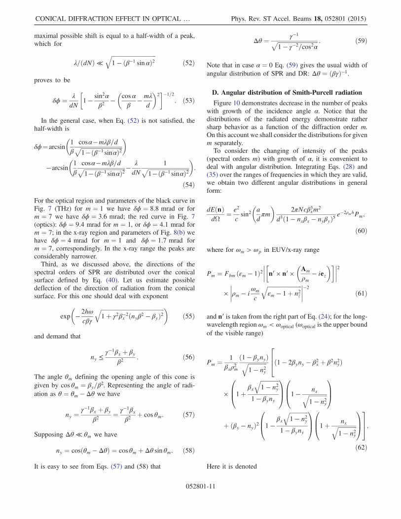
For the optical region and parameters of the black curve inFig. 7 (THz) for m ¼ 1 we have δϕ ¼ 8.8 mrad or form ¼ 7 we have δϕ ¼ 3.6 mrad; the red curve in Fig. 7(optics): δϕ ¼ 9.4 mrad for m ¼ 1, or δϕ ¼ 4.1 mrad form ¼ 7; in the x-ray region and parameters of Fig. 8(b) wehave δϕ ¼ 4 mrad for m ¼ 1 and δϕ ¼ 1.7 mrad form ¼ 7, correspondingly. In the x-ray range the peaks areconsiderably narrower.Third, as we discussed above, the directions of the
spectral orders of SPR are distributed over the conicalsurface defined by Eq. (40). Let us estimate possibledeflection of the direction of radiation from the conicalsurface. For this one should deal with exponent
exp
�− 2hω
cβγ
ffiffiffiffiffiffiffiffiffiffiffiffiffiffiffiffiffiffiffiffiffiffiffiffiffiffiffiffiffiffiffiffiffiffiffiffiffiffiffiffiffiffiffiffi1þ γ2β−2x ðnyβ2 − βyÞ2
q �ð55Þ
and demand that
ny ≤γ−1βx þ βy
β2: ð56Þ
The angle θm defining the opening angle of this cone isgiven by cos θm ¼ βy=β2. Representing the angle of radi-ation as θ ¼ θm − Δθ we have
ny ¼γ−1βx þ βy
β2¼ γ−1βx
β2þ cos θm: ð57Þ
Supposing Δθ ≪ θm we have
ny ¼ cosðθm − ΔθÞ ¼ cos θm þ Δθ sin θm: ð58Þ
It is easy to see from Eqs. (57) and (58) that
Δθ ¼ γ−1ffiffiffiffiffiffiffiffiffiffiffiffiffiffiffiffiffiffiffiffiffiffiffiffiffiffiffiffi1 − γ−2=cos2α
p : ð59Þ
Note that in case α ¼ 0 Eq. (59) gives the usual width ofangular distribution of SPR and DR: Δθ ¼ ðβγÞ−1.
D. Angular distribution of Smith-Purcell radiation
Figure 10 demonstrates decrease in the number of peakswith growth of the incidence angle α. Notice that thedistributions of the radiated energy demonstrate rathersharp behavior as a function of the diffraction order m.On this account we shall consider the distributions for givenm separately.To consider the changing of intensity of the peaks
(spectral orders m) with growth of α, it is convenient todeal with angular distribution. Integrating Eqs. (28) and(35) over the ranges of frequencies in which they are valid,we obtain two different angular distributions in generalform:
dEðnÞdΩ
¼ e2
csin2�adπm
�2πNcβ3xm2
d3ð1 − nxβx − nyβyÞ5e−2ρmhPm;
ð60Þ
where for ωm > ωp in EUV/x-ray range
Pm ¼ Fbm ðεm − 1Þ2�����n0 × n0 ×
�Am
ρm− iez
������2
×
����ρm − iωm
c
ffiffiffiffiffiffiffiffiffiffiffiffiffiffiffiffiffiffiffiffiffiffiffiffiεm − 1þ n2z
q ����−2 ð61Þ
and n0 is taken from the right part of Eq. (24); for the long-wavelength region ωm < ωoptical (ωoptical is the upper boundof the visible range)
Pm ¼ 1
βxρ2m
ð1 − βynyÞffiffiffiffiffiffiffiffiffiffiffiffiffi1 − n2y
q264ð1 − 2βyny − β2x þ β2n2yÞ
×
0B@1þ
βx
ffiffiffiffiffiffiffiffiffiffiffiffiffi1 − n2y
q1 − βyny
1CA0B@1 − nxffiffiffiffiffiffiffiffiffiffiffiffiffi
1 − n2yq
1CA
þ ðβy − nyÞ20B@1 − βx
ffiffiffiffiffiffiffiffiffiffiffiffiffi1 − n2y
q1 − βyny
1CA0B@1þ nxffiffiffiffiffiffiffiffiffiffiffiffiffi
1 − n2yq
1CA375:
ð62Þ
Here it is denoted
CONICAL DIFFRACTION EFFECT IN OPTICAL … Phys. Rev. ST Accel. Beams 18, 052801 (2015)
052801-11

εm ¼ 1 − ω2p
ω2m; ωm ¼ 2πmcβx
dð1 − nxβx − nyβyÞ;
ρm ¼ ωm
cβγ
ffiffiffiffiffiffiffiffiffiffiffiffiffiffiffiffiffiffiffiffiffiffiffiffiffiffiffiffiffiffiffiffiffiffiffiffiffiffiffiffiffiffiffiffi1þ γ2β−2x ðnyβ2 − βyÞ2
q;
Am ¼ ωm
cβxð1 − nyβy − β2x; βxðny − βyÞ; 0Þ;
Fbm ¼����1 − exp
�−bρm þ ib
ωm
c
ffiffiffiffiffiffiffiffiffiffiffiffiffiffiffiffiffiffiffiffiffiffiffiffiεm − 1þ n2z
q �����2: ð63Þ
The angular distribution for the fifth order of SPR is shownin Fig. 11. One can see that up to some definite value ofangle the intensity increases, after this decreases, and thisbehavior is the same for two different physical models validfor two different ranges of frequencies. However, the theorymay lose its applicability at the angles less than thatcorresponding to maximum of the radiation, and in thiscase the function can increase over all the range of permitangles—see the red curve in Fig. 11. The distributions inFig. 11 are plotted for two different gratings and parametersof beam for optical and lower frequencies and for UV andx-ray frequencies, respectively.
VI. SUMMARY AND CONCLUDING REMARKS
The theory of Smith-Purcell radiation has been con-structed for x-ray, EUV, optical, and THz ranges. For high-frequency range (EUV/x-rays) the analytical expressionshave been obtained directly from Maxwell’s equations andare presented here for the first time. For the lowerfrequencies of optical and THz ranges we constructedthe theory of SPR proceeding from the known generaliza-tion [22] of one of the most powerful approaches in thetheory of diffraction radiation [13]. Our results are valid for
arbitrary energies of the charged particles, from nonrela-tivistic to ultrarelativistic. We stress the conical effect inSPR—the strong spatial redistribution of the SPR peaks(spectral orders) over a conical surface. This effect was firstinvestigated by Haeberle et al. [15] proceeding from thewell-known van den Berg approach [10], which, however,does not always work well for ultrarelativistic energies[16], and demands additional difficult numerical calcula-tions into the bargain. In contrast with that we suggest afully analytic description displaying important new featuresof radiation.The spectral and angular distributions of SPR show
strong dependence on the angle α between a particlevelocity and the normal to the rulings direction. Spatialdistributions of the SPR peaks for different spectral rangesare proved to have a lot in common; on the other hand, thereare also some differences, which were analyzed in detail inSec. V. The angular distribution of SPR as a function of αhas a maximum (Fig. 11); the spectral and angulardistribution in the EUV/x-ray region has a sharp maximum[Fig. 9(b)] owing to the contribution of evanescent waves:see the discussion after Eqs. (25) and (48). We cannot assertthat the same behavior—sharp peaks due to evanescentwaves—will occur in other spectral ranges, but for non-metal targets we believe it to be so.Redistribution of radiation from the plane to the cone
occurs when α ¼ 0 becomes α ≠ 0 and therefore will play avital part for divergent beams.Modern and prospective high-brightness electron beams having small transverse dimen-sions, the beams from laser-plasma sources, and nonrelativ-istic beams—all these need allowance to be made fordivergence in order to construct a correct theory. Also, thedistribution of radiation caused by the interaction of chargedparticles with photonic crystal (including targets made ofmetamaterial, which often is a crystal) should be stronglyinfluenced by the conical effect considered here in detail.EUV and x-ray SPR have not been observed experimen-
tally so far, but we are sure that shortwave DR and SPR havegreat potential for submicron noninvasive beam diagnosticsof high-brightness ultrarelativistic beams. Also, our theoryof x-ray SPR is valid in the water-window range(λ ¼ 4.47–2.36 nm) where x-ray radiation is not absorbedby water vapor; development of radiation sources withtunable radiation spectrum in this frequency range is impor-tant in practical applications in medicine and biology. Also,noninvasive beam diagnostics in this frequency range is veryattractive for ultrarelativistic super high-brightness beams.For example, the size of the focal spot in ILC is expected to beabout 8 nm, needing detection with an accuracy of somenanometers, which is not provided by existing techniquesand demands developing short-wave schemes of diagnostics.Thus, our results may be of importance for beam
diagnostic systems and for designing of new sources ofelectromagnetic radiation in different frequency ranges,including free-electron lasers.
OpticsX Ray
0.5 1.0 1.5rad
5
10
15
20
25
30
35
dE
d10 3eV
FIG. 11. Angular distribution of the fifth peak (fifth order) ofSPR for optical region (red dashed curve) and for x-ray region(black curve). It is plotted using Eqs. (60)–(63) for optical regionγ ¼ 1710 (energy of Mainz Microtron MAMI), d ¼ 9 μm,h ¼ 127 μm, ϕ ¼ 0.9 rad; and for x-ray region γ ¼ 4 × 10⁴
(energy of SLAC), ℏωp ¼ 26.1 eV (beryllium), d ¼ 0.9 μm,h ¼ 60 μm, ϕ ¼ 0.3 rad, εðωÞ ¼ 1 − ω2
p=ω2m. For both of the
curves N ¼ 20, m ¼ 5, a ¼ d=2, θ ¼ arccosðβ−1 sin αÞ. Thedashed line corresponds to the angles breaking the inequalityωm < ωoptical for λoptical ¼ 2πc=ωoptical ¼ 380 nm.
SERGEEVA, TISHCHENKO, AND STRIKHANOV Phys. Rev. ST Accel. Beams 18, 052801 (2015)
052801-12

ACKNOWLEDGMENTS
We are grateful to Professor A. P. Potylitsyn for stimu-lating discussions. The work was supported by the Ministryof Education and Science of the Russian Federation, GrantNo. 3.1110.2014/K.
[1] S. J. Smith and E. M. Purcell, Phys. Rev. 92, 1069 (1953).[2] A. P. Potylitsyn, M. I. Ryazanov, M. N. Strikhanov, and
A. A. Tishchenko, Diffraction Radiation from RelativisticParticles (Springer, Berlin, 2011).
[3] P. Rullhusen, X. Artru, and P. Dhez, Novel RadiationSources Using Relativistic Electrons (World Scientific,Singapore, 1998).
[4] A. A. Ponomarenko, M. I. Ryazanov, M. N. Strikhanov,and A. A. Tishchenko, Nucl. Instrum. Methods Phys. Res.,Sect. B 309, 223 (2013); W. Knulst, M. J. van der Wiel,O. J. Luiten, and J. Verhoeven, Appl. Phys. Lett. 83, 4050(2003); A. Smirnov, A high performance, FIR radiatorbased on laser driven e-gun, in Photonics ResearchDevelopments, edited by V. P. Nilsson (Nova SciencePublishers, Inc., Hauppauge, New York, 2008).
[5] I. V. Konoplev, A. J. MacLachlan, C. W. Robertson, A. W.Cross, andA. D. R. Phelps, Phys. Rev.A 84, 013826 (2011).
[6] L. Schachter and A. Ron, Phys. Rev. A 40, 876 (1989); D.Li, M. Hangyo, Y. Tsunawaki, Z. Yang, Y. Wei, S.Miyamoto, M. R. Asakawa, and K. Imasaki, Appl. Phys.Lett. 100, 191101 (2012); J. Gardelle, P. Modin, and J. T.Donohue, Phys. Rev. Lett. 105, 224801 (2010); J. D.Jarvis, H. L. Andrews, and C. A. Brau, Phys. Rev. STAccel. Beams 13, 020701 (2010).
[7] F. J. Garcia de Abajo, Rev. Mod. Phys. 82, 209 (2010); H. L.Andrews et al., Phys. Rev. ST Accel. Beams 17, 052802(2014).
[8] P. Karataev, S. Araki, R. Hamatsu, H. Hayano, T. Muto, G.Naumenko, A. Potylitsyn, N. Terunuma, and J. Urakawa,Phys. Rev. Lett. 93, 244802 (2004); A. Cianchi, V.Balandin, M. Castellano, E. Chiadroni, L. Catani, N.Golubeva, K. Honkavaara, G. Kube, and M. Migliorati,New J. Phys. 16, 113029 (2014).
[9] V. P. Shestopalov, The Smith-Purcell Effect (Nova SciencePublishers, Commack, NY, 1993).
[10] P. M. van den Berg, J. Opt. Soc. Am. 63, 689 (1973)(in Russian).
[11] J. H. Brownell, J. Walsh, and G. Doucas, Phys. Rev. E 57, 1(1998); J. H. Brownell and G. Doucas, Phys. Rev. STAccel. Beams 8, 091301 (2005).
[12] A. P. Potylitsyn, Nucl. Instrum. Methods Phys. Res., Sect.B 145, 60 (1998).
[13] A. P. Kazantsev and G. I. Surdutovich, Sov. Phys. Dokl. 7,990 (1963).
[14] D. V. Karlovets, J. Exp. Theor. Phys. 113, 27 (2011).[15] O. Haeberle, P. Rullhusen, J.-M. Salome, and N. Maene,
Phys. Rev. E 55, 4675 (1997).[16] G. Kube et al., Phys. Rev. E 65, 056501 (2002).[17] A. A. Tishchenko, A. P. Potylitsyn, and M. N. Strikhanov,
Phys. Rev. E 70, 066501 (2004).
[18] A. A. Tishchenko, M. N. Strikhanov, and A. P. Potylitsyn,Nucl. Instrum. Methods Phys. Res., Sect. B 227, 63 (2005).
[19] A. A. Tishchenko, A. P. Potylitsyn, and M. N. Strikhanov,Phys. Lett. A 359, 509 (2006).
[20] D. Yu. Sergeeva, A. A. Tishchenko, and M. N. Strikhanov,Nucl. Instrum.Methods Phys.Res., Sect. B 309, 189 (2013).
[21] D. Yu. Sergeeva, M. N. Strikhanov, and A. A. Tishchenko,in Proceedings of the 4th International ParticleAccelerator Conference, IPAC-2013, Shanghai, China,2013 (JACoW, Shanghai, China, 2013), p. 616.
[22] N. Potylitsina-Kube and X. Artru, Nucl. Instrum. MethodsPhys. Res., Sect. B 201, 172 (2003).
[23] S. Yamaguti, J. Inoue, O. Haeberle, and K. Ohtaka, Phys.Rev. B 66, 195202 (2002); N. Horiuchi et al., Phys. Rev. E74, 056601 (2006); A. Yanai and U. Levy, Opt. Express 20,18515 (2012).
[24] M.-E. Couprie et al., in Proceedings of 36th InternationalFree Electron Laser Conference FEL 2014, Basel, Switzer-land, 2014 (JACoW, Basel, 2014), p. 569.
[25] G. H. Spenсer and M. V. R. K. Murty, J. Opt. Soc. Am. 52,672 (1962).
[26] M. Neviere, D. Maystre, and W. R. Hunter, J. Opt. Soc.Am. 68, 1106 (1978).
[27] E. N. Hogert, M. A. Rebollo, and N. G. Gaggioli, OpticsLaser Technol. 23, 341 (1991).
[28] B. Dolgoshein, Nucl. Instrum. Methods Phys. Res., Sect. A326, 434 (1993).
[29] L. Durand, Phys. Rev. D 11, 89 (1975).[30] A. A. Tishchenko and D. Yu. Sergeeva, in Proceedings of
36th International Free Electron Laser Conference FEL2014, Basel, Switzerland, 2014 (JACoW, Basel, 2014),p. 384.
[31] D. Yu. Sergeeva and A. A. Tishchenko, in Proceedings of36th InternationalFreeElectronLaserConferenceFEL2014,Basel, Switzerland, 2014 (JACoW, Basel, 2014), p. 378.
[32] M. V. Shevelev and A. S. Kon’kov, J. Exp. Theor. Phys.118, 501 (2014).
[33] M. I. Ryazanov, M. N. Strikhanov, and A. A. Tishchenko,J. Exp. Theor. Phys. 99, 311 (2004); I. P. Ivanov and D. V.Karlovets, Phys. Rev. A 88, 043840 (2013).
[34] M. J. Moran, Phys. Rev. Lett. 69, 2523 (1992).[35] L.M. Brekhovskikh, Usp. Fiz. Nauk 38, 1 (1949) (in
Russian).[36] A. A. Tishchenko, M. N. Strikhanov, and A. P. Potylitsyn,
UV and x-ray Smith-Purcell radiation, in Book ofAbstracts of VIII International Symposium “Radiationfrom Relativistic Electrons in Periodic Structures,”RREPS-2009, Zvenigorod, Russia, 2009, p. 50.
[37] V. V. Syshchenko and N. F. Shulga, J. Surf. Invest.: X-Ray,Synchrotron Neutron Tech. 5, 392 (2011).
[38] S. J. Glass and H. Mendlowitz, Phys. Rev. 174, 57 (1968).[39] O. Haeberle, P. Rullhusen, J.-M. Salome, and N. Maene,
Phys. Rev. E 49, 3340 (1994).[40] D. V. Karlovets and A. P. Potylitsyn, Phys. Rev. ST Accel.
Beams 9, 080701 (2006).[41] T. Muto, S. Araki, R. Hamatsu, H. Hayano, T. Hirose, P.
Karataev, G. Naumenko, A. Potylitsyn, and J. Urakawa,Phys. Rev. Lett. 90, 104801 (2003).
[42] D. V. Karlovets and A. P. Potylitsyn, Phys. Lett. A 373,1988 (2009).
CONICAL DIFFRACTION EFFECT IN OPTICAL … Phys. Rev. ST Accel. Beams 18, 052801 (2015)
052801-13