conference part 2 - · pdf fileclinker cooler kiln burner chlorine crashed raw secondary...
TRANSCRIPT

Technology Presentations

6. Technology Presentations
6.1 Destruction Technologies for ODSin Japan
Dr. Koichi Mizuno, Japan

Destruction Technologies for Ozone Depleting Substances in Japan
Koichi Mizuno
National Institute for Resources and Environment
1. Guidelines and Management Manual for CFC Destruction
Because of the importance of the destruction of ozone depleting substances, the Government ofJapan has issued both the Guidelines and the Management Manual for CFC destructiontechnologies.
The first set of Guidelines was issued in May 1996 and they were amended in March 1999. Theamended Guidelines include:
• Confirmation of Destruction: Coinjection of ODS into the destruction equipment, destructionefficiency, frequency of check up
• Hazardous Emissions: national and local emission standards, measurement methods (JapanIndustrial Standards; JIS), frequency of monitoring
• Operational Stability: monitoring of temperature and exhaust gas, frequency of check up
The Management Manual for CFC destruction facilities has also been issued by the Government ofJapan in May 2000. The Manual aims at the safe and environmentally sound management in view ofmore than 30 current facilities and an expected increase of the facilities. Up to now, more than 800copies of the Manual have been distributed.
The Manual includes:
1) Overviews of Destruction
2) Management of Handling of CFCs in the Facilities
− acceptance of CFCs to the facilities
− recovery of CFCs in the facilities
− transfer of CFCs contained in cylinder to the storage tank
− storage of CFCs
− charge of CFCs into the destruction equipment
3) Management of Destruction Technologies in Six Categories
− waste incineration: rotary kiln, municipal waste direct melting furnace,fixed-bed two-stage combustion
− destruction by manufacturingplant:
cement kiln, lime rotary kiln
− incineration in water: liquid injection (submerged combustion), gaseous/fume oxidation (high-temperature steam decomposition)

− plasma: r.f. plasma, microwave plasma, arc plasma− catalytic process: TiO2-type catalyst, AlPO4-type catalyst
− others: thermal vaporization
4) Targets of management
− destruction efficiency: equal to or more than 99.99%
− safe operation: corrosion prevention and so forth
− minimum emission standards: PCDD/PCDF and other pollutants in airemissions, water effluents, and solid residue
2. Commercial Destruction Technologies in Practice
The locations of destruction facilities in Japan are shown in Figure 1. More than 30 facilities with awide variety of destruction technologies and capacities are being operated.
Figure 1. Locations of CFC Destruction Facilities in Japan
Rotary kilnCement kilnLime rotary kilnMunicipal waste direct melting furnaceCatalytic processHigh-temperature steam decompositionr.f. Plasma
Submerged combustionChemical thermal decomposition
arc Plasma
Thermal vaporizationFixed-bed two-stage combustion
Hokkaido
Honshu
Shikoku
KyushuOkinawa

3. Brief Description of Typical Destruction Technologies in Japan
3.1 IncinerationThere are many test data of CFC destruction by incineration available in Japan. An example amongthem is the gaseous/fume oxidation method owned by the ICI-Teijin Fluorochemicals Co., Ltd.(ITF) in Mihara City, Hiroshima Prefecture (see Figure 2). This destruction technology is also calledthe high-temperature steam decomposition, since a large amount of steam is fed into the furnace.Injection of fuel, steam, and air into the furnace gave rise to such a high temperature, approximately1,200-1,250oC, that the destruction efficiency achieved was more than 99.999%. The ratedthroughput of CFCs ranged from 15 to 165 kg/hr. In a destruction test using a mixture of CFC-12and HCFC-22, the emissions of HCl, HF, CO, particulates, SO2, and NOx met the standards, andthe PCDD/PCDF emissions to the atmosphere were below 0.03 ng-TEQ/Nm3.
Figure 2. Flow Diagram of the Gaseous/Fume Oxidation Method
(High-temperature Steam Decomposition)
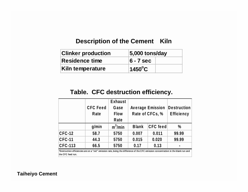
3.2 Cement KilnThe destruction experiments using a cement kiln were carried out at the Chichibu Plant No.2 inSaitama Prefecture, which is owned by the Taiheiyo Cement Corporation. The kiln was a dry rotarytype equipped with a new suspension preheater (NSP), with a diameter of 5.5 m and a length of 83m. The plant produces clinker for ordinary Portland cement with a manufacturing capacity of 5,000tonnes per day. CFC-11, CFC-12, and CFC-113 were fed through an auxiliary fuel injection portat the rates ranging from 2.7 kg/h to 3.72 kg/h, depending on the type of CFCs fed (see Figure 3).Since the furnace temperature was as high as 1,450 oC and the gas residence time was 6-7 sec, thedestruction of CFCs achieved was more than 99.99% (see Table 1). The emissions of HCl, HF,PCDD/PCDF, and other twelve halogenated organic compounds were measured. The total
Steam ?120kgs/h
LPG ?45kg/h
CFC or HCFC Gas ?165kgs/h
Cylinder
Gas CollectionTank
Air ?700kgs/h
TICChamber
?1250oC
Air BlowerCooling
Tank
CW
Cooling Air
1250kgs/h
O
2
AR
Sampling PointScrubber
Basic Water
Waste AcidHold Tank Neutralisation
Tank
Ca(OH)2 Slurry
CaCl2 aq.
ClarifierSludgeMixingTank
Filtre PressFiltrate
Sampling Point
Water
Basic Water Tank
By-Produced CaF2
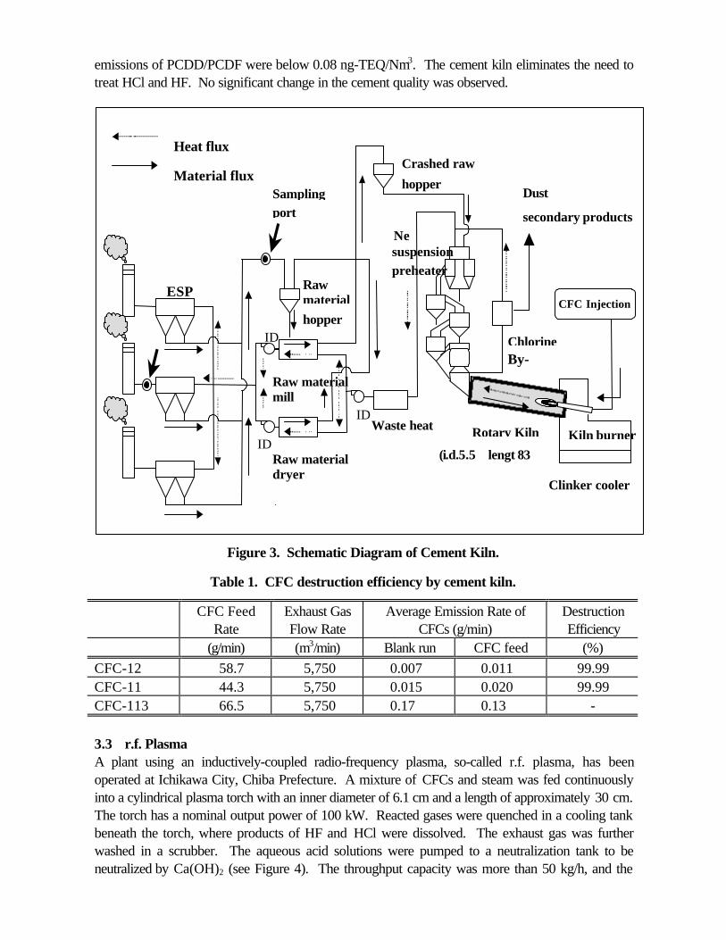
emissions of PCDD/PCDF were below 0.08 ng-TEQ/Nm3. The cement kiln eliminates the need totreat HCl and HF. No significant change in the cement quality was observed.
Figure 3. Schematic Diagram of Cement Kiln.
Table 1. CFC destruction efficiency by cement kiln.
CFC FeedRate
Exhaust GasFlow Rate
Average Emission Rate ofCFCs (g/min)
DestructionEfficiency
(g/min) (m3/min) Blank run CFC feed (%)
CFC-12 58.7 5,750 0.007 0.011 99.99CFC-11 44.3 5,750 0.015 0.020 99.99CFC-113 66.5 5,750 0.17 0.13 -
3.3 r.f. PlasmaA plant using an inductively-coupled radio-frequency plasma, so-called r.f. plasma, has beenoperated at Ichikawa City, Chiba Prefecture. A mixture of CFCs and steam was fed continuouslyinto a cylindrical plasma torch with an inner diameter of 6.1 cm and a length of approximately 30 cm.The torch has a nominal output power of 100 kW. Reacted gases were quenched in a cooling tankbeneath the torch, where products of HF and HCl were dissolved. The exhaust gas was furtherwashed in a scrubber. The aqueous acid solutions were pumped to a neutralization tank to beneutralized by Ca(OH)2 (see Figure 4). The throughput capacity was more than 50 kg/h, and the
Rotary Kiln
CFC Injection
Clinker cooler
Kiln burner
Chlorine
Crashed raw
secondary productsNe
Waste heatboiler
Raw
Raw material
Raw material
ESP
Sampling
IDF
IDF
IDF
Heat flux
Material flux
mill
dryer
hopper
suspensionpreheater
By-pass
(i.d.5.5 lengt 83
material
hopper
Dusttoport
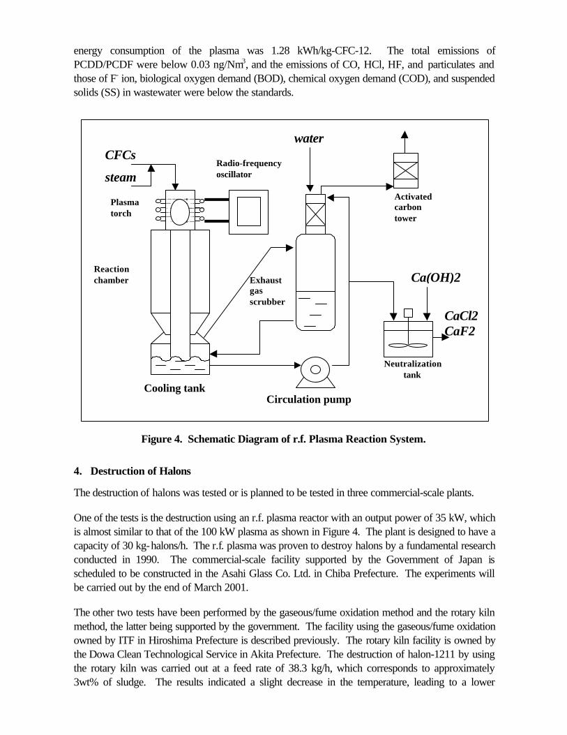
energy consumption of the plasma was 1.28 kWh/kg-CFC-12. The total emissions ofPCDD/PCDF were below 0.03 ng/Nm3, and the emissions of CO, HCl, HF, and particulates andthose of F- ion, biological oxygen demand (BOD), chemical oxygen demand (COD), and suspendedsolids (SS) in wastewater were below the standards.
Figure 4. Schematic Diagram of r.f. Plasma Reaction System.
4. Destruction of Halons
The destruction of halons was tested or is planned to be tested in three commercial-scale plants.
One of the tests is the destruction using an r.f. plasma reactor with an output power of 35 kW, whichis almost similar to that of the 100 kW plasma as shown in Figure 4. The plant is designed to have acapacity of 30 kg-halons/h. The r.f. plasma was proven to destroy halons by a fundamental researchconducted in 1990. The commercial-scale facility supported by the Government of Japan isscheduled to be constructed in the Asahi Glass Co. Ltd. in Chiba Prefecture. The experiments willbe carried out by the end of March 2001.
The other two tests have been performed by the gaseous/fume oxidation method and the rotary kilnmethod, the latter being supported by the government. The facility using the gaseous/fume oxidationowned by ITF in Hiroshima Prefecture is described previously. The rotary kiln facility is owned bythe Dowa Clean Technological Service in Akita Prefecture. The destruction of halon-1211 by usingthe rotary kiln was carried out at a feed rate of 38.3 kg/h, which corresponds to approximately3wt% of sludge. The results indicated a slight decrease in the temperature, leading to a lower
Plasmatorch
Radio-frequencyoscillator
Reactionchamber
Cooling tank
Activatedcarbontower
Exhaustgasscrubber
Circulation pump
Neutralizationtank
CFCs
steam
water
Ca(OH)2
CaCl2CaF2

destruction efficiency of 99.753% and slight increases of PCDD/PCDF emissions. However, asmaller feed rate of halons (the rotary kiln) or a higher temperature (the gaseous/fume oxidation)gave the destruction efficiency of more than 99.99% and the reduction of air pollutants emissionsincluding dioxins.
Destruction Technologies for Ozone DepletingSubstances in Japan
Koichi MizunoNational Institute for Resources and Environment
Agency of Industrial Science and TechnologyMinistry of International Trade and Industry of Japan

! Guidelines for CFC Destruction: issued in May 1996, amended in March 1999
" Confirmation of Destruction: injection of ODS into the equipment,destruction efficiency, frequency of check up
" Hazardous Emissions: national and local emission standards,measurement methods (Japan Industrial Standards; JIS), frequency of monitoring
" Operational Stability: monitoring of temperature and exhaust gas,frequency of check up
! Manual for Destruction of Chlorofluorocarbons: issued May 2000• Background• Procedures in Preparation of this Manual• Management of Facilities Concerning Fluorocarbon Destruction3.1 Explanation
3.2 Management of Technology and Facilities for Fluorocarbon Destruction 3.2.1 Management of the Storage of Fluorocarbon Recovered 3.2.2 Management Index of Fluorocarbon Destruction Facilities (equipment)
Incineration with Waste / Incineration in Manufacturing Processes / SubmergedCombustion / Plasma / Catalytic Destruction / Other Systems
3.2.3 Management Indexes for Emissions from Installations due to FluorocarbonDestruction
[Reference] Items Related to Achievement Record of Fluorocarbon Destruction
Guidelines and Manual for Destruction
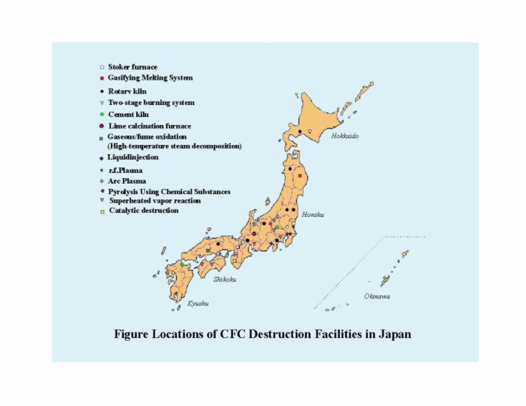

Figure. Flow Diagram of Gaseous/Fume Oxidation (High-temperature Steam Decomposition)
ICI-Teijin Fluorochemicals Co., Ltd.
Steam ~ ~ ~ ~120kgs/h
LPG ~LPG ~LPG ~LPG ~45kg/h
CFC or HCFC Gas ~~~~165 kgs/h
Cylinder
Gas CollectionTank
Air ~~~~700kgs/h
TICChamber~~~~1250oC
Air Blower CoolingTank
CW
Cooling Air
1250 kgs/h
O2AR Sampling PointScrubber
Basic Water
Waste AcidHold Tank Neutralisation
Tank
Ca(OH)2 SlurryCaCl2 aq.
ClarifierSludgeMixingTank
Filtre Press Filtrate Sampling Point
Water
Basic Water Tank
By-Produced CaF2
ICI-Teijin
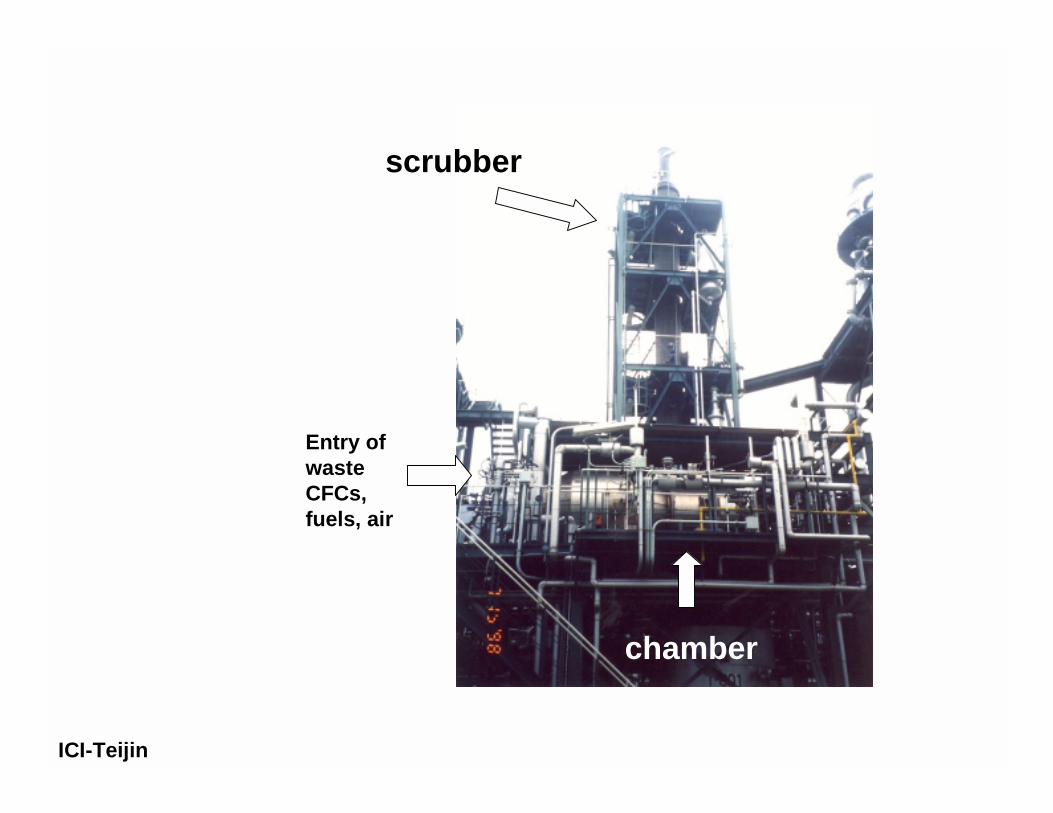
scrubber
chamber
Entry ofwasteCFCs,fuels, air
ICI-Teijin

Injection ports of waste CFCs, fuels, and air
ICI-Teijin
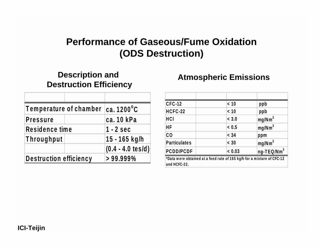
T em perature of chamber ca. 1200oCPressure ca. 10 kPaResidence tim e 1 - 2 secT hroughput 15 - 165 kg/h
(0 .4 - 4.0 tes/d)Destruction effic iency > 99.999%
CFC-12 < 10 ppbHCFC-22 < 10 ppbHCl < 3.0 mg/Nm3
HF < 0.5 mg/Nm3
CO < 34 ppmParticulates < 30 mg/Nm3
PCDD/PCDF < 0.03 ng-T EQ /Nm3
*Data w ere obta ined at a feed rate of 165 kg/h for a m ixture of CFC-12and HCFC-22.
Atmospheric EmissionsDescription and Destruction Efficiency
Performance of Gaseous/Fume Oxidation(ODS Destruction)
ICI-Teijin

Figure. Liquid injection incineratorAsahi Glass
Chamber
Cooling watertank
EvaporatorCylinder
Neutralization tank
Ca(OH)2
Scrubber
to Air
Water
NaOH
Filter press
to Wastewatertreatment
Fuel

Asahi Glass
Liquid injection incinerator
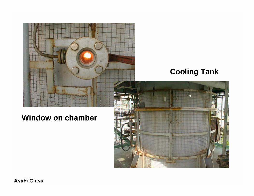
scrubberchamber and cooling tank
Asahi Glass
Cooling Tank
Window on chamber

Asahi Glass
T em perature of cham ber 1,350oCResidence tim e 1.3 secT hroughput ca.11 kg/h
(5 - 10 wt% )Destruction effic iency > 99.99%
CFCs < 1 ppmHCl < 10 mg/Nm3
HF < 1 mg/Nm3
CO < 10 ppmParticulates < 20 mg/Nm3
PCDD/PCDF < 0.52 ng-TEQ/Nm3
F- < 15 mg/LpH -SS < 50 mg/LPCDD/PCDF < 0.062 pg-TEQ/L
Atmospheric Emissions
Effluents water
Description and Destruction Efficiency
Performance of Liquid Injection Incinerator

Rotary kiln(i.d. 5.5 m; length 83 m)
CFC Injection
Clinker cooler
Kiln burner
Chlorineby-pass
Crashed rawmaterial hopper
NewSuspensionpreheater
Waste heat boiler
RawMaterialhopper
Raw materialmill
Raw materialdryer
ESP
Samplingport
IDF
IDF
IDF
Heat flux
Material flux
Dust tosecondary products
Figure Schematic Diagram of Cement KilnTaiheiyo Cement
CFC Fe edRate
ExhaustG aseFlowRate
DestructionEfficie ncy
g/min m3/min Blank CFC fe ed %CFC-12 58.7 5750 0.007 0.011 99.99CFC-11 44.3 5750 0.015 0.020 99.99CFC-113 66.5 5750 0.17 0.13 -
Av erage EmissionRate of CFCs, %
*Destruction efficiencies are on a "net" emission rate, being the dif ference of the C FC emission concentrat ion in the b lank run andthe CFC feed run .
Clinker production 5,000 tons/dayResidence time 6 - 7 secKiln temperature 1450oC
Table. CFC destruction efficiency.
Description of the Cement Kiln
Taiheiyo Cement
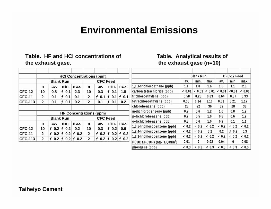
n av. min. max. n av. min. max.CFC-12 10 0.8 ƒ 0.1 2.3 10 0.3 ƒ 0.1 1.8CFC-11 2 0.1 ƒ 0.1 0.1 2 ƒ 0.1 ƒ 0.1 ƒ 0.1CFC-113 2 0.1 ƒ 0.1 0.2 2 0.1 ƒ 0.1 0.2
n av. min. max. n av. min. max.CFC-12 10 ƒ 0.2 ƒ 0.2 0.2 10 0.3 ƒ 0.2 0.6CFC-11 2 ƒ 0.2 ƒ 0.2 ƒ 0.2 2 ƒ 0.2 ƒ 0.2 ƒ 0.2CFC-113 2 ƒ 0.2 ƒ 0.2 ƒ 0.2 2 ƒ 0.2 ƒ 0.2 ƒ 0.2
CFC FeedHF Concentrations (ppm)
Blank Run CFC FeedHCI Concentrations (ppm)
Blank Run
Table. HF and HCl concentrations of the exhaust gase.
av . min. max. av . min. max.1,1,1-trichloroe thane (ppb) 1.1 1.0 1.6 1.5 1.1 2.0carbon te trachloride (ppb) < 0.01 < 0.01 < 0.01 < 0.01 <0.01 < 0.01trichloroe thyle ne (ppb) 0.58 0.28 0.83 0.64 0.37 0.93te trachloroe thyle ne (ppb) 0.50 0.14 1.10 0.61 0.21 1.17chlorobe nze ne (ppb) 28 22 36 32 28 38m-dichlorobe nze ne (ppb) 0.9 0.6 1.2 1.0 0.8 1.2p-dichlorobe nze ne (ppb) 0.7 0.5 1.0 0.8 0.6 1.2o-dichlorobe nze ne (ppb) 0.8 0.6 1.0 0.9 0.1 1.11,3,5-trichlorobe nze ne (ppb) < 0.2 < 0.2 < 0.2 < 0.2 < 0.2 < 0.21,2,4-trichlorobe nze ne (ppb) < 0.2 < 0.2 0.2 0.2 ƒ 0.2 0.31,2,3-trichlorobe nze ne (ppb) < 0.2 < 0.2 < 0.2 < 0.2 < 0.2 < 0.2
PC D Ds/PC D Fs (ng-T EQ /Nm3) 0.01 0 0.02 0.04 0 0.08phosge ne (ppb) < 0.3 < 0.3 < 0.3 < 0.3 < 0.3 < 0.3
B lank Run C FC-12 Fe e d
Table. Analytical results of the exhaust gase (n=10)
Environmental Emissions
Taiheiyo Cement

Rotary kiln
Neutralization
Secondary Chamber(After burner)
Mist Cottrell precipiator
Fuel
Waste CFC
Flow Diagram of Rotary Kiln
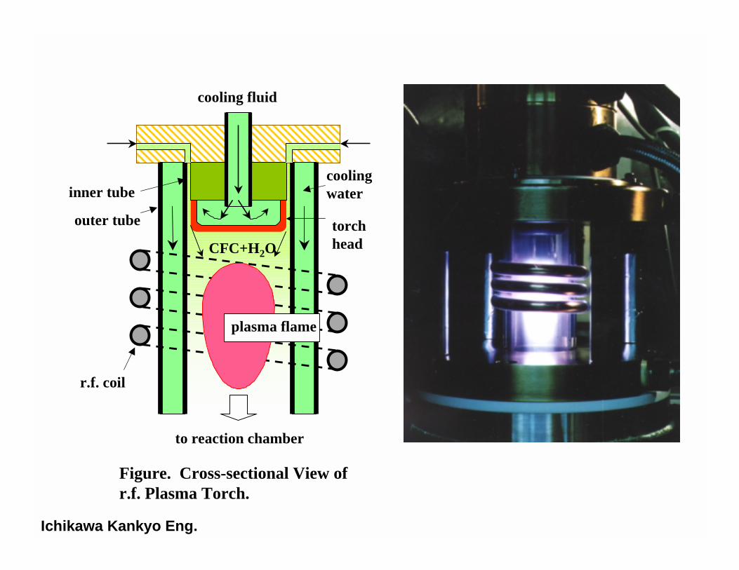
cooling fluid
CFC+H2O
inner tube
outer tube
r.f. coil
to reaction chamber
coolingwater
plasma flame
torchhead
Figure. Cross-sectional View ofr.f. Plasma Torch.
Ichikawa Kankyo Eng.

Plasmatorch
Radio-frequencyoscillator
Reactionchamber
Cooling tank
Activatedcarbontower
Exhaustgasscrubber
Circulation pump
Neutralizationtank
CFCs
steam
water
Ca(OH)2
CaCl2
CaF2
Figure. Schematic Diagram of r.f. PlasmaReaction System.
Photo. A Commercial Plant atIchikawa City, Chiba Prefecture
Ichikawa Kankyo Eng.
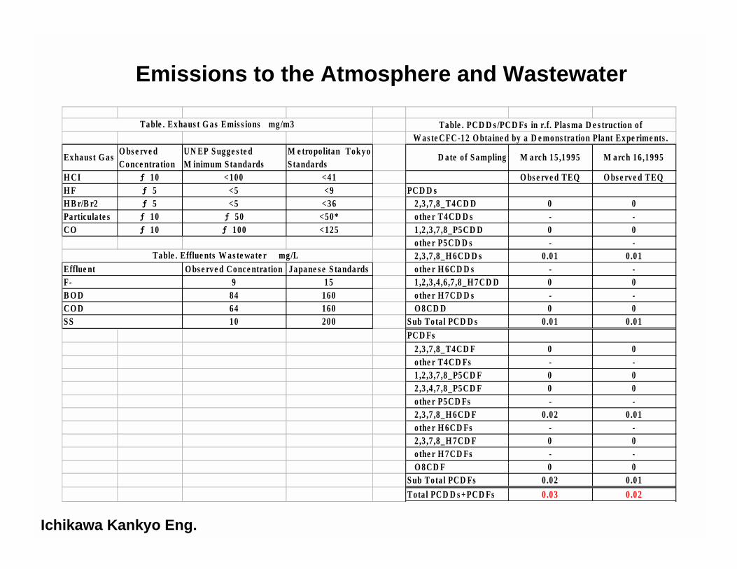
Exhaus t G asO bs e rve dConce ntration
UN EP S ugge s te dM inimum S tandards
M e tropolitan Tok yoS tandards
D ate o f S ampling M arch 15 ,1995 M arch 16 ,1995
H CI ƒ 10 <100 <41 O bs e rve d TEQ O bs e rve d TEQH F ƒ 5 <5 <9 PC D D sH B r/B r2 ƒ 5 <5 <36 2 ,3 ,7 ,8_T4CD D 0 0Particulate s ƒ 10 ƒ 50 <50* o the r T4CD D s - -CO ƒ 10 ƒ 100 <125 1 ,2 ,3 ,7 ,8_P5CD D 0 0
o the r P5CD D s - - 2 ,3 ,7 ,8_H 6CD D s 0.01 0 .01
O bs e rve d Conce ntration Japane s e S tandards o the r H 6CD D s - -9 15 1 ,2 ,3 ,4 ,6 ,7 ,8_H 7CD D 0 0
84 160 o the r H 7CD D s - -64 160 O 8CD D 0 010 200 S ub Tota l PCD D s 0.01 0 .01
PC D Fs 2 ,3 ,7 ,8_T4CD F 0 0 o the r T4CD Fs - - 1 ,2 ,3 ,7 ,8_P5CD F 0 0 2 ,3 ,4 ,7 ,8_P5CD F 0 0 o the r P5CD Fs - - 2 ,3 ,7 ,8_H 6CD F 0.02 0 .01 o the r H 6CD Fs - - 2 ,3 ,7 ,8_H 7CD F 0 0 o the r H 7CD Fs - - O 8CD F 0 0S ub Tota l PCD Fs 0 .02 0 .01
Tota l PCD D s +PCD Fs 0 .03 0 .02
Table . PCD D s /PC D Fs in r.f. Plas ma D e s truction ofW as te CFC-12 O bta ine d by a D e mons tration Plant Expe rime nts .
Table . Efflue nts W as te wate r mg/L
S S
Table . Exhaus t G as Emis s ions mg/m3
Efflue ntF-B O DCO D
Emissions to the Atmosphere and Wastewater
Ichikawa Kankyo Eng.
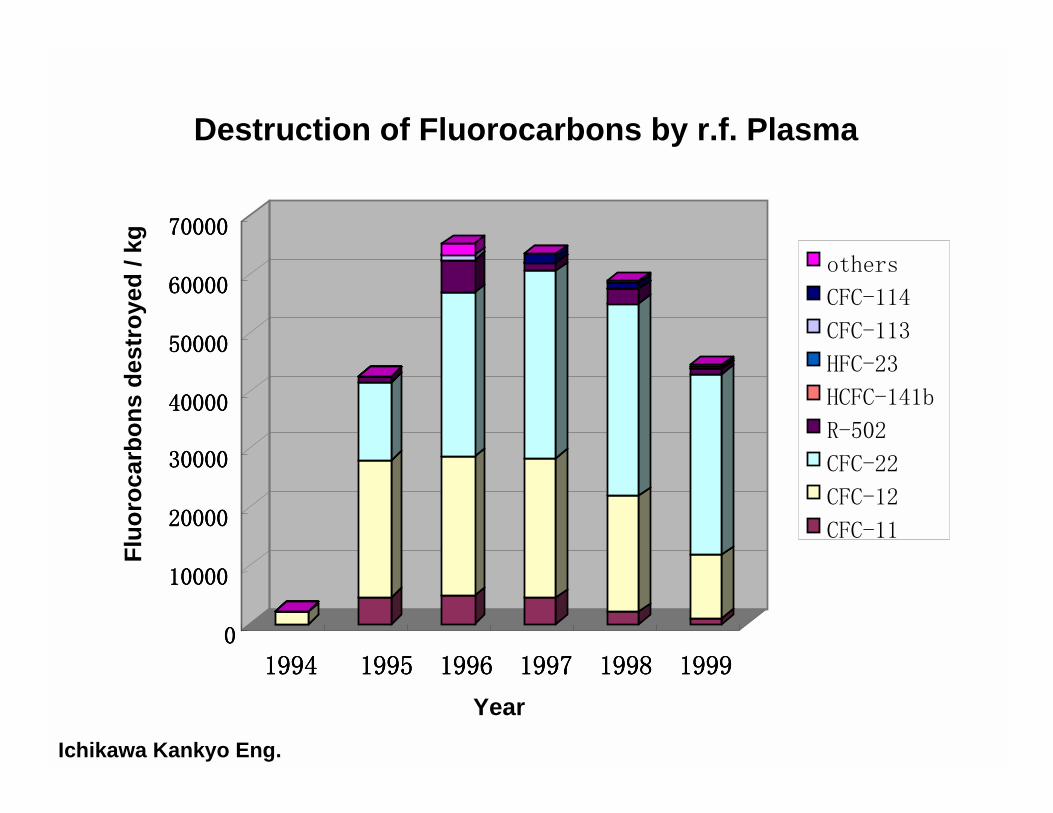
0000
10000100001000010000
20000200002000020000
30000300003000030000
40000400004000040000
50000500005000050000
60000600006000060000
70000700007000070000
1994199419941994 1995199519951995 1996199619961996 1997199719971997 1998199819981998 1999199919991999
others
CFC-114
CFC-113
HFC-23
HCFC-141b
R-502
CFC-22
CFC-12
CFC-11
Flu
oro
carb
on
s d
estr
oye
d /
kg
Year
Destruction of Fluorocarbons by r.f. Plasma
Ichikawa Kankyo Eng.

Fe ed rate Halon-1211 38.3 (av aragekg/hHalon-2402 40 kg/h
De struction Efficiency Halon-1211 99.753 %Halon-2402 99.88% %
Fe ed rate of sludge 1,392 kg/hT e mpe rature in kiln Blank 997 - 1,009oC
Halon-1211 922 - 984oCHalon-2402 921 - 974oC
Rotary Kiln
at Higher Feed Rates of Halons
Blank Hal 1 Hal 2
Nm3/hr(WB) 8,200 8,400 11,800Nm3/hr(DB) 6,000 6,100 8,600
humid % 26.3 27.8 26.3Particulates mg/Nm3 < 1 < 1 <1O2 % 10.9 11.2 10.6CO2 % 8 7.6 8.1CO ppm 11 13 14HCl ppm < 1 10 51Cl2 ppm 2 2 11.4HF ppm < 0.5 < 0.5 < 0.5HBr ppm < 0.5 8.6 39SO2 ppm < 1 <1 < 1NOx ppm 84 63 47halone-1211 ppb - 2,100 -Halon-2402 ppb - - 500CF4 ppb - < 2 8.8C2F6 ppb - < 2 < 2PCDD/PCDF ng-TEQ/Nm3 0.15 2.5 1.4chlorobenzenes ng/Nm3 1,100 1,600 2,200chlorophenols ng/Nm3 210 59 46
Exhaust gas

Fee d rate Halon-1211 20 kg/hHalon-2402 20 kg/h
Destruction Efficiency Halon-1211 99.99 %Halon-2402 99.55% %
Fee d rate of sludge 1,392 kg/hT e mperarue in kiln Halon-1211 992 - 1,057 oC
Halon-2402 989 - 1,045 oC
Halon-1211 Hal 2
Nm3/hr(WB) 39,900 36,300Nm3/hr(DB) 27,800 25,800
humid % 30.4 29Particulates mg/Nm3 1 1O2 % 11.9 12CO2 % 7.2 6.7CO ppm 20 7HCl ppm < 1 < 1HF ppm < 0.5 < 0.5HBr ppm < 1 < 1SO2 ppm 2.9 2.2NOx ppm 78 80halone-1211 ppb < 10 -Halon-2402 ppb - 130CFC-12 ppb 25 < 10PCDD/PCDF ng-TEQ/Nm3 0.35 0.28chlorobenzenes ng/Nm3 7,500 40,000chlorophenols ng/Nm3 1,500 400
Exhaust gas
Rotary Kiln
at Lower Feed Rates Of Halons

•
first run second runFeed@rate of halon-1301
temperature of furnaceFeed rate of steamresidence time
15.2 (avarage) kg/h1,250oC
1 - 2 kg/hca. 2.4 sec
first run second run
Particulates mg/Nm3 < 20 < 20SO2 ppm < 2 < 2NOx ppm 82 83CO ppm 27 33HCl ppm < 1.2 < 1.4
HF mg/Nm3 ƒ 0.3 ƒ 0.3Br2 ppm ƒ 2.0 < 2.0CF4 ppb < 10 ƒ 10
C2F6 ppb < 1 ƒ 1
chlorobenzenes ng/Nm3 420 590
chlorophenols ng/Nm3 60 80
PCDD/PCDF/Co-PCBs ng-TEQ/Nm3 0.0000025 0
brominated dioxins ng-TEQ/Nm3 0 0
Destruction Conditions Atmospheric Emissions
ICI-Teijin
Destruction of Halons by Gaseous/Fume Oxidation
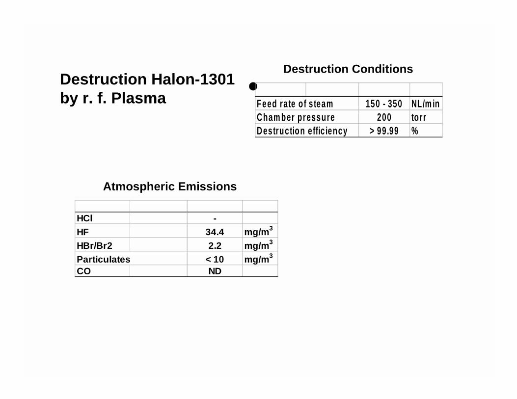
•Feed rate of steam 150 - 350 NL/m inCham ber pressure 200 torrDestruction effic iency > 99.99 %
HCl -HF 34.4 mg/m3
HBr/Br2 2.2 mg/m3
Particulates < 10 mg/m3
CO ND
Atmospheric Emissions
Destruction ConditionsDestruction Halon-1301 by r. f. Plasma
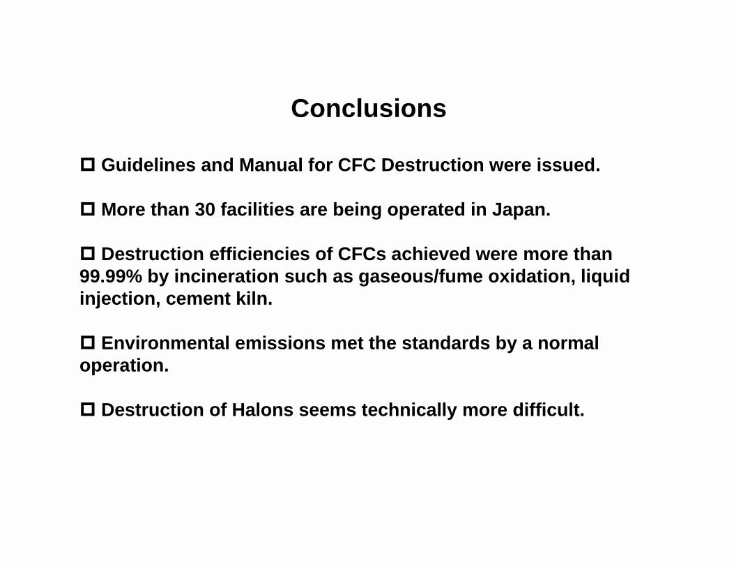
Conclusions
! Guidelines and Manual for CFC Destruction were issued.
! More than 30 facilities are being operated in Japan.
! Destruction efficiencies of CFCs achieved were more than99.99% by incineration such as gaseous/fume oxidation, liquidinjection, cement kiln.
! Environmental emissions met the standards by a normaloperation.
! Destruction of Halons seems technically more difficult.