condition survey and non destructive evalution of concrete
TRANSCRIPT

CONDITION SURVEY AND NON DESTRUCTIVE EVALUTION
AVINASH KUMAR GUPTA
CCW TRAINING INSTITUTE
NEW DELHI
07/04/2017
CONDITION SURVEY
• Examination of concrete • For identifying and defining areas of distress.• Recording history from inception to
completion and subsequent life.

Objective
• Identify cause of distress and sources• Assess: extent of distress due to corrosion,
fire, earthquake, any other reason• Asses residual strength of structure and its
rehabilitability• Prioritize the distressed elements as per
seriousness.• To select and plan the effective remedy.

Stages of condition survey
• Prioritize distressed elements according to seriousness for repairs.
• a) Preliminary inspection• b) Planning• c)Visual Inspection• d) Field and laboratory testing.
Preliminary inspection
• History of structure from client, owner, occupants, General public in building,
• Note records, previous repairs history and expenses done for the same.
• All possible data and information.• Practical restriction in survey and safety
requirements for survey team.• Extent and quantum of survey work • Time required ( survey and execution ) • Advise immediate safety measures

Information gathering
• . Period of construction• Construction details (drg,arch,structural )• Exposure conditions• Designed and present use of structure.• Previous changes in use• Record of structural changes if done.• Record of 1st occurrence of defect.• Details of repairs carried out previously.• Previous reports etc.• Details from owner, photographs

Planning survey
• Field documents• Plans and actual observations each room-
wise.• Previous report , advise if any and
implementation done as per report,• Grouping of structural elements ( external,
interior etc )• Exposure conditions

Classification of damage
• Class O : No distress but cosmetic repairs• Class 1 : Minor repairs ( superficial repairs )• Class 2 : Medium repairs ( patch repairs )
(minor structure cracks)• Class 3 : Principal repairs (spalling of cover
concrete,structural cracks,cracks along bars)• Class O : Major repairs(replacement of
structural Members)

Grade for Assessment of the building
• Based on the inspection and observation the distress level of the selected buildings may be categorizedas mentioned below:
• G1 – No distress observed• G1 – Minor distress observed in few structural members, which can
be repaired under the advice of a structural engineer.• G2 – Medium distress observed in few structural members, which
can be repaired / rehabilitated including strengthening with the advice of a structural engineer
• G3 – Severe distress observed in some of the structural members, which can be rehabilitated including strengthening with the advice of a structural engineer.
• G4 – Severe distress is observed which could prove dangerous, hence evacuation at an early date is required.

Visual Inspection
• Workmanship, structural serviceability, material deterioration mechanism
• General health( structural and non structural elements)• Preparation of estimate / bill of quantities.• Quantify extent of distress• Photographic record.• Obstructions for visual inspection to be noted.• Understanding structural system / deviations • Leakage , seepage due to inadequate drainage system• Types of cracks and its pattern• Color and texture of concrete surface (chemical attack or
disintegration by way of leaching

Record
• Areas of high distress• Cracks and their locations• Excessive deflections• Exposure conditions of various distressed areas.• Moisture / seepage / leakages / dampness
locations.• Abnormal vibrations in structure.• Algae, fungus growth, trees on structure.• Photographic record.• Areas of immediate concern

Considerations for repairs strategy
• Identification of cause of problem.• Assessment and extent of damage.• Availability space and accessibility w.r.t.
ongoing activities in building.• propping structural members in case of major
repairs , severely damaged elements (columns etc ).
• Safety measures to avoid mishaps

Non destructive Evaluation tests
• These tests do not impair performance of the member, They are field or laboratory tests.
• Put under five categories based on purpose,
In-situ-Concrete strengthChemical attackCorrosion activityFire damageStructural integrity and soundness

Non Destructive Testing
• Nondestructive testing in the broad sense refers to methods whereby internal characteristics of solid structures can be examined without permanently affecting the structure. Thus, parts that prove to be satisfactory under specified test conditions are not degraded by the test procedures

NDT , Introduction
• Nondestructive testing (NDT) is the process of inspecting, testing, or evaluating materials, components or assemblies for discontinuities, or differences in characteristics without destroying the serviceability of the part or system. In other words, when the inspection or test is completed the part can still be used

NDT- Purpose
•-Assessment of Existing Structures in the Absence of Drawings.•-Quick assessment of the structure

NDT -Advantages
• Access to hidden items – “see through walls”
• Better investigations with NDT• Rapid accumulation of data• Generally less expensive than destructive
testing.

NDT - Disadvantages
1. More than one test method may be required
2. Environmental conditions may effect or distort results
3. Construction details & building components may effect results
4. Some conditions cannot be determined with a reasonable degree of accuracy without destructive testing

Non destructive Testing
• A : In- situ-concrete test• - rebound hammer• - Ultrasonic pulse velocity• - Windsor probe• - Pull out test : • Core cutting / sampling, lab testing of cores • - Load test

Non destructive Testing
• B : Chemical attack• Carbonation test• Chloride test• Sulphate test• C: Corrosion potential assessment• Cover meter ( checking cover)• Half cell potential• Resistivity meter • Permeability ( air and water )
Non destructive Testing.
• D: Fire damage assessment• Thermo gravimetric analysis (TGA)• Differential Thermal analysis (DTA)• X-ray diffraction (XRD)• E: Structural Integrity/ soundness• Ultrasonic pulse velocity ( discontinuities, cracks
and depth of cracks)• Radiography• Impact echo test

• The rebound hammer can provide a fairly accurate estimate of concrete compressive strength.
• The concrete should be 14 to 56 days old.• Surface Condition:• The surface of the concrete at the point tested
must be smooth, dry, and free of honeycombing. Otherwise, rebound readings will be low Indicating a weaker concrete than is actually the case. The rubbing stone provided can be used to grind the surface smooth, if necessary

Location of Test PointsLocation of Test Points
• The concrete to be tested must be at least four inches thick: It is also recommended that readings be taken only where the concrete has been in contact with the form. These conditions are most easily satisfied if the readings are taken along the edge of the tank on the sides and ends where the adjoining concrete face (i.e., wall, top, or bottom) can support the point of contact.


PROCEDURE
• Remove hammer from case and press the plunger end against a hard surface to release the plunger from the locked position. (Do not press lock button while doing this.)
• Position hammer horizontally with plunger end against wall at a point.
• Slowly apply pressure until hammer fires. This will occur when only approximately 1/2 inch of the plunger is still visible. Do not press the lock button during this step.

• A). Remove hammer from case and press the plunger end against a hard surface to release the plunger from the locked position. (Do not press lock button while doing this.)
• B). Position hammer horizontally with plunger end against wall at a point.
• C). Slowly apply pressure until hammer fires. This will occur when only approximately 1/2 inch of the plunger is still visible. Do not press the lock button during this step

Procedure Contd.• With the hammer still pressed against the
wall, read the rebound number off the scale provided on the hammer. If it is necessary to move the hammer before reading, press the lock button. The rebound number should be read to two significant figures.
• Repeat the above procedure at different points around the wall until a total of ten readings has been taken


This is based on the principle that the velocity of an ultrasonic pulse through any material depends upon the density. Comparatively higher velocity is obtained when concrete quality is good in terms of density, uniformity etc.
Pulse Velocity measurements can be used to assess the presence of cracks, voids etc., quality of concrete relative to standards requirements.

UPV Test contd.
There are three possible ways of measuring pulse velocity. i) Direct transmissionii) Semi direct transmissioniii) Indirect transmission (surface probing)
Out of the three methods, the direct transmission method is considered to be the best


condition of concrete based on pulse velocity are given below
S.No. Pulse Velocity Condition of concrete I in(Km/Sec.)•1. Above 4.5 Excellent•2. 3.5 to 4.5 Good•3. 3.0 to 3.5 Medium•4. Below 3.0 Poor

PULLOUT TESTPULLOUT TEST• The fundamental principle behind pull out testing
with LOK-test and CAPO test is that the test equipment designed to a specific geometry will produce results (pull-out forces) that closely correlate to the compressive strength of concrete.
The first method ,using the cast steel disc is called LOK test. The second method shown in fig.2 using expandable ring is called CAPO test (i.e. Cut and Pull out Test). The diameter of both the disc and ring is 25mm. the distance to the concrete surface is also 25mm. the inner diameter of the counter-pressure is 55mm.


The relationship between the pullout force Fu in kN and compressive strength Fc in MPa
The relationship between the pullout force Fu in kN and compressive strength Fc in MPa is given in fig
04/14/17 38

Pull out tests are used toPull out tests are used to Determine in-situ compressive strength of the
concrete Ascertain the strength of concrete for
carrying out post tensioning operations. Determine the time of removal of forms and
shores based on actual in-situ strength of the structure.
Terminate curing based on in-situ strength of the structure

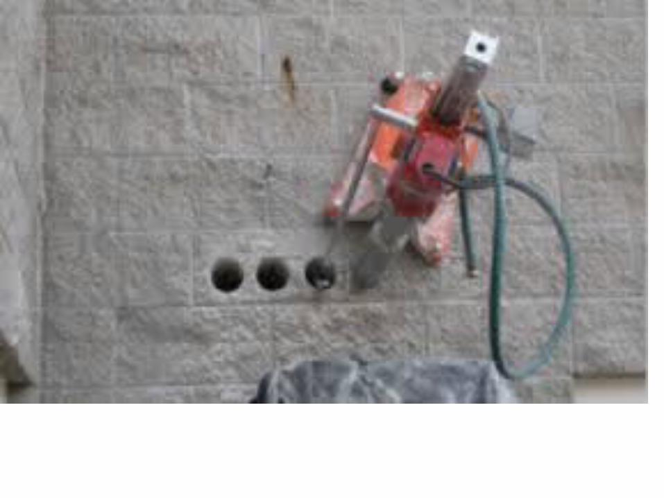
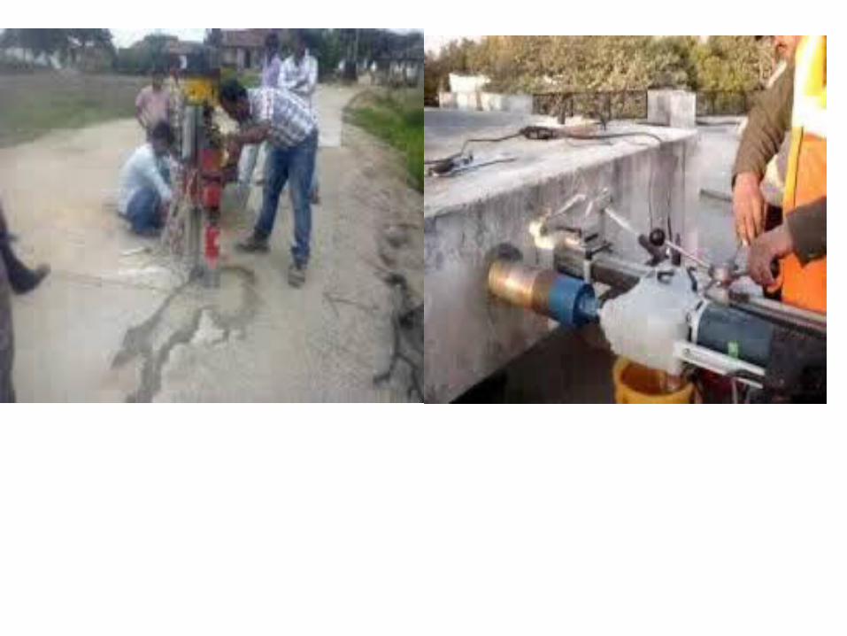
4.Core cutter4.Core cutterThe test should be taken at points where
minimum strength and maximum stress are likely to coincide. But, at the same time, the core cutting causes some damage to the member and may impair the future performance of the member. Therefore, in slender members, the core should be taken away from the critical section. For compression testing, the diameter of the core should be at least three times the nominal maximum aggregate size
Core Cutter is used to cut the core from the existing concrete structure for testing the physical properties of the concrete like compressive strength, density, water absorption, crack depth and chemical test like depth of carbonation and chloride content etc. It can also be used to inspect the interior region of the structural members.
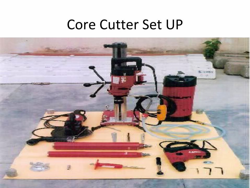
Core Cutter Set UP

• Cover meters are electromagnetic in operation. Electric currents in a coil winding in the search head generate a magnetic field which propagates through the concrete and will interact with any buried metal present, such as reinforcing steel.It is the generic term for equipment used to locate steel reinforcing bar in concrete and to estimate the thickness of the concrete cover over the reinforcement
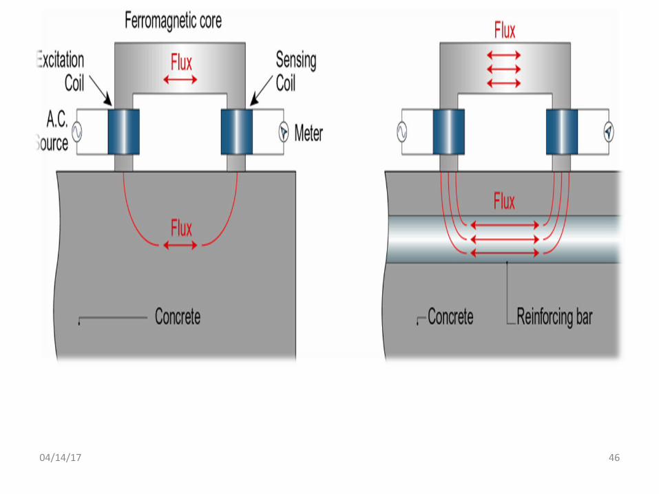
04/14/17 46

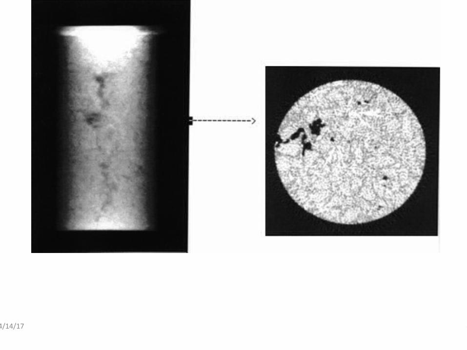
Tomography means imaging an object by taking measurements from “slices” of its cross-section.
Tomography means imaging an object by taking measurements from “slices” of its cross-section.
04/14/17 47
04/14/17 48

04/14/17 49
This test is carried out to assess the quality / uniformity of concrete at various depths. The instrument consists of a four probe device. Electrical current is passed through the outer probes & the potential drop is measured by the inner probes. From the current & voltage drop measurements, the resistivity of concrete can be measured. Electrical resistivity = 2(pi)aE/i (in kilo-ohm cm) where a = distance between probes = 5 cm in the 1st set of readings = 10 cm in the 2nd set of readings E = potential difference between inner two probes in mV
Most useful test in tunnel structure

