concrete and masonry structures 2 part m:...
TRANSCRIPT

Concrete and MasonryStructures 2
Part M: Masonry

Introduction
� Petr Bílý [email protected]
� people.fsv.cvut.cz/www/bilypet1/133CM02.htm
� Office no. B731
� Office hours: Tuesday 09:00
Friday 09:00

Seminar task
� Design of masonry house in sloping terrain� Structural analysis, drawings

Homework - page layout
� A4 onesided, handwritten by pencil
� Each calculation:� General formula� Substitution of numbers� Result
� Loads – in tables
� Quote units
� WELL-ARRANGED!!!
5 cm
MEd = 1/8*f*L2
MEd = 1/8*8*52
MEd = 25 kNm
Load Char. γF Design
… … 1,35 …
… … 1,50 … .
TOTAL

Advice for calculations
� Use N, mm and MPa units and you will not have any problems with the units anymore ☺
� The only problem is with moments – you get moments in Nmm. This unit is not used in practice => divide by 1,000,000 to get kNm

Before you begin…
� Visit teacher´s website
� Read the task
� Find your individual parameters
� Get familiarized with masonry units used in our building

1st part: Design of slab
� Preliminary design of combined slab above 1st floor using tables
� Draw a detail of slab-wall joint

Preliminary design
� Calculation of loadings – self-weight not included in this stage
� Slab depth estimation
Load Char. γF Design
… … 1,35 …
… … 1,50 … .
TOTAL
Dead load
Live load
1 1
25 20h L
≈ −

Preliminary design
� Design of the slabs using tables� Length and spacing of girders� Depth of the slab � Type of brick inserts

Slab-wall joint
+ Dimensions
+ Annotate all the elements
- Do not use internal insulation
! Collar min. 200 mm

2nd part: Design of lintels
� Design of ceramic lintels using tables
� Details of lintel-slab joint and window head

Design of ceramic lintels
� Lintels above the widest window opening (w)

Design of ceramic lintels
� Calculation of load
� flintel,d = fslab,d*L/2 + ρm,d*t*h [kN/m]
� kN/m3 = kg/m3 / 100
L/2
w
Including self-weight

Design of ceramic lintels
� Design of lintels using tables� Type of lintel used� Clear span and bedding length of lintel� Number of lintels required
� If collar brick is used, the lintel beneath it can not be considered to resist the loading!

Detail of lintel-slab joint
+ Dimensions
+ Annotate all the elements
- Do not use internal insulation
! Collar min. 200 mm

Detail of window head
+ Dimensions
+ Annotate all the elements

3rd part: Assembling drawing
� Use scale 1:50
� CAD system or handmade drawing – your choice
� Leave free space for staircase (don´t design the staircase)
� Adjust the dimensions of the structure in accordance with modular dimensions of masonry used

Assembling drawing
� Plan of ceiling + vertical supports � One section in each direction

Assembling drawing
Vertical structures =
heavy solid line
Horizontal structures =
narrow solid line
Axes of girders = narrow dash-
dot line
Sections = bold solid line
Detailed assembling - only for a part of the
plan

Assembling drawing
Joists, brick inserts in section - schematically
Details of connections to walls/lintels
=

Assembling drawing
Dimensions – openings, walls, depth of the slab, thickness of the wall…
Annotations – lintels, joists, brick inserts
Hatches – types of masonry,
concrete

Assembling drawing
Masonry = bricks + mortar!!!
Legend of materials and
elements
Drawing Title
Notes
The example drawing shows DIFFERENT structure –apply the rules to YOUR structure

Assembling drawing
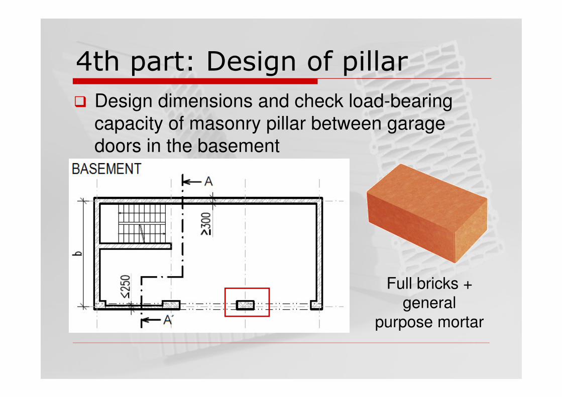
4th part: Design of pillar
� Design dimensions and check load-bearing capacity of masonry pillar between garage doors in the basement
Full bricks + general
purpose mortar

Strength of masonry
� fu – strength of the material, matches the strength label of the units: Pxy => fu = xy MPa. Determined by laboratory tests.
� fb – compressive strength of the units, fb = δ.fu� fm – strength of the mortar. MCxy => xy MPa
� δ – factor expressing the effect of dimensions of the brick, see table

� fk – characteristic compressive strength ofmasonry
� K – coefficient, see table
Strength of masonry
0.7 0.3
k b mf Kf f=

Strength of masonry

Strength of masonry
� K coefficient – the value from the table has to be multiplied by 0,8 if longitudinal perpend joint exists in the pillar/wall
� Solid clay bricks => volume of pores = 0 %

� fd – design compressive strength of masonry
� γM – partial factor for material, use 2,2
Strength of masonry
kd
M
ff
γ=

Load
� Load from slabs, self-weight of the walls, parapet on the roof from tributary area from allfloors
L/2
B

Snow load
� Characteristic snow load:
� µi – snow load shape coefficient, for flat roof 0,8
� Ce – exposure coefficient, for normal topography1,0
� Ct – thermal coefficient, for normal conditions 1,0
� s – basic snow load according to snow map
k i e ts C C sµ=

Snow load

� Maximum normal force in the bottom of the pillar in basement (without self-weight of the pillar) => Nmax
� Estimation:
� Design (with respect to the dimensions of masonry units):
Design of dimensions
maxreq
d0,7
NA
f=
reqA A b t≥ → ×

� Criterion:
� hef = ρn.hp, hp = clear height of the pillar
� For walls restrained at the top and bottom by solid slabs, take ρn = 0,75
� tef = min (b, t)
Slenderness ratio
ef
ef
27h
t≤

A. Top of the pillar – eccentricload, high vertical load
B. Effect of slenderness(possibility of buckling)
NEd,A = Nmax
NEd,B = Nmax + ½ self-weightof the pillar
Cross-sections to be checked
A
B

A. Draw detail and calculate eccentricity. Example:
B. One half of eccentricity in A
Eccentricity due to loads

� A – cross-sectional area of the wall
� Φi – capacity reduction factor
Rd,i i dN Af= Φ
Vertical resistance – A
ii
21
e
tΦ = − i if ia 0.05e e e t= + ≥ ef
ia450
he =
Thickness of the pillar
Total eccentricity
Eccentricity due to loads
Initial eccentricity
Minimum eccentricity

� Φm – capacity reduction factor, see table
Rd,m m dN Af= Φ
Vertical resistance – B
mf ma kmk 0.05e e ee
t t
+ += ≥ mf if
efma
k
0.5
450
0
e e
he
e
≈
=
≈Relative eccentricity
Eccentricity due to loads
Eccentricity due to creep
Initial eccentricity
Minimum relative eccentricity

Vertical resistance – B

Resistance check
� In practice: If any of the criteria is not met, the pillar should be redesigned!!!
� In the homework: If any of the criteria is not met, propose a change to improve load-bearing capacity of the pillar
Rd,i Ed,A
Rd,m Ed,B
N N
N N
≥
≥

� Important for good load distribution
� RULE: Continuous perpend joint is not allowedElevation:
� Bricks you can use
� RULE: Queen closer should not be placed on the edge of the cross-section
Bond of bricks
OK NOK
Full brick
¾ bat
Half bat
Queen closer

� Example: Pillar 300 x 750 mm made from classic full bricks (290/140/65 mm)
� Plan:
Bond of bricks
OK NOK

� Using simplified method according to Eurocode 6, check the load-bearing capacity of basement wall loaded by earth pressure at rest
5th part: Basement wall
Hollow bricks + thin layer
mortar or foam

Simplified Method: Rules

� Lateral:
� Vertical:
� NEd,min ≡ characteristic value of vertical dead loads in the section of the wall in the middle of backfill height
� NEd,max ≡ design value of vertical dead+live loads in the section of the wall in the middle of backfill height
� FEd = lateral force effect of the backfill
� NRd = vertical load-bearing capacity of the wall
Simplified Method: Conditions 2
eEd,min Ed
e
bhhN F
t
γ
β≥ =
dEd,max Rd
3
btfN N≤ =

� γ – density of soil (backfill), see assignment
� b – width of the wall, take b = 1 m and calculate the forces per 1 m
� h – clear height of the wall
� he – height of the backfill, he = h
� t – thickness of basement wall, 300 mm for POROTHERM 30
� fd – design strength of masonry
Simplified Method: Conditions

� βe – coefficient to involve horizontal spanning (L) of the wall
Simplified Method: Equations
2 20
40
2 60 20
e
e
e
L h
L h
Lh L h
h
β
β
β
≥ → =
≤ → =
< < → = −

� Use the same approach as for pillar with following changes:
� Blocks connected by thin layer mortar or foam => no effect of mortar, characteristic strength is:
� Volume of pores (holes) = 52 %
� No longitudinal perpend joint => don´t multiply K by 0,8
� Use γM = 2,0 (designed, not prescribed mortar)
Strength of masonry
0.7
k bf Kf=

� Increase thickness of the wall
� Use masonry of higher strength (applicable only if vertical condition is not met)
� Use reinforced masonry (ditto)
� Design strengthening pillars
� Design reinforced concrete basement
=> Choose one of the measures if your wall doesn‘t meet the criteria!
If the capacity is not enough:

6th part: Wind loaded wall
� Check load-bearing capacity of wind-loaded non-bearing masonry wall next to garage doors
Hollow bricks + general
purpose mortar

� Non-bearing masonry is laterally loaded, vertical load is very small => possibility of flexural failure
� Wall = „two-way slab“
Wind loaded masonry

� Design wind load: wd = wk*1,5 (partial factor)
� Characteristic wind load wk [kN/m2]
� qb – reference mean velocity pressure [kN/m2]
� ρ – air density, 1,25 kg.m-3
� vb – basic wind velocity (defined from a map in EC 1991-1-4), see assignment
Wind load
k b e pew q c c=
2
b b
1
2q vρ= You will recieve the value
in [Pa] = [N/m2] => divide by 1000 to recieve kN/m2

Wind load

� ce – exposure factor, see graph below� Terrain category – III (suburb) or IV (dowtown)� z – in our case, the height of the building
Wind load

� cpe – pressure coefficient
Wind load
b
D E
d
elevation

Flexural strength of masonry
� fxk1 – characteristic flexural strength in the plain plane of failure parallel to the bed joints
[MPa]
5 MPa 5 MPa

Flexural strength of masonry
� fxk2 – char. flex. strength in the plane of failure perpendicular to the bed joints
[MPa]
5 MPa 5 MPa

� Design values of flexural strength:
� γM = 2,2 (prescribed mortar)
Flexural strength of masonry
xk1xd1 d
M
xk2xd2
M
ff
ff
σγ
γ
= +
=

� σd – stress from the vertical loading in the critical cross-section, i.e. the stress from the self-weight of upper half of the wall
� ρm – density of filling masonry (14 kN.m-3)
Flexural strength of masonry
[ ]md MPa
1000 2
h
t
ρσ = ⋅

� µ – orthogonal ratio of flexural strengths
Design bending moment
2
Ed,y d
2
Ed,x d
M w L
M w L
µα
α
=
=
xd1
xd2
f
fµ =
� Formulae [kNm/m]:

� α – bending moment coefficient, see table
Design bending moment
Wall support condition E = wall is simply supported
on all four edges

� Formulae [kNm/m]:
� Z – elastic section modulus per 1 meter of the wall [m3/m]:
� t – thickness of the wall, t = 175 mm (thickness „without plaster“)
Moment of resistance
Rd,y xd1
Rd,x xd2
M f Z
M f Z
=
=
2
6
tZ =

Resistance check
� In practice: If any of the criteria is not met, the wall should be redesigned!!!
� In the homework: If any of the criteria is not met, propose a change to improve load-bearing capacity of the wall (reinforced masonry, higher thickness…)
Rd,y Ed,y
Rd,x Ed,x
M M
M M
≥
≥

Thank you for your attention