conceptual architecture planning for manned geo satellite servicingaseegsw.com/past proceedings/2013...
TRANSCRIPT
Proceedings of the 2013 ASEE Gulf-Southwest Annual Conference,
The University of Texas at Arlington, March 21 – 23, 2013.
Copyright 2013, American Society for Engineering Education
Friday Morning Session 2 - Student
Conceptual Architecture Planning for Manned Geo Satellite Servicing
Lex Gonzalez, Gary Coleman, Eric Haney, Amit Oza, Vincent Ricketts, Bernd Chudoba
Mechanical and Aerospace Engineering Department
University of Texas at Arlington
Paul Czsyz
Hypertech Concepts LLC
Abstract
In an effort to quantify the feasibility of candidate space architectures for manned geostationary
(GEO) satellite servicing (MGS), NASA and DARPA have teamed up with the Aerospace
Vehicle Design (AVD) Laboratory at the University of Texas Arlington (UTA) in order to
provide a conceptual assessment of architecture/concept of operations/technology combinations.
The primary challenge has been the exploration of past, present, and future in-space investments
in the context of mission performance, mission complexity, and industrial capability.
Consequently, this study necessitated the use of a simulation capability to assess and visualize
the physical design drivers and sensitivities of the operational and technical domain.
The overall goal of the study has been the development of a system with the capability to transfer
payload to and from GEO. To this end the following concepts of operations (ConOp) have been
studied: direct insertion/reentry (ConOp 1), and launch to low earth orbit (LEO), at Kennedy
Space Center (KSC) inclination angle, with an orbital transfer to/from GEO (ConOp 2). The
technology elements traded varied between hardware for in-space maneuvers, aero-assisted
maneuvers, and reentry vehicles.
This report introduces the AVD Laboratory’s product development and technology forecasting
methodology as applied to the problem introduced above. Because the focus of this activity has
been on the exploration of the available solution space, a unique screening process has been
employed to assess the implication of (a) the mission, (b) hardware/technology selection, and (c)
the operational scenarios on key research objectives to be defined.
The study concludes that a Capsule + Descent Propulsion Module (DPM) system sized for the
MGS mission is feasible for a direct insertion/reentry concept of operation. Vehicles sized for
orbital transfer from LEO-KSC to GEO-0, and back to LEO-KSC (ConOp 2) show a total mass
savings when utilizing Aero-assisted Orbital Transfer Vehicle (AOTV) DPM options compared
to the pure propulsive baseline case. Overall, the selection between AOTV concepts and a

Proceedings of the 2013 ASEE Gulf-Southwest Annual Conference,
The University of Texas at Arlington, March 21 – 23, 2013.
Copyright 2013, American Society for Engineering Education
reusable/expendable Ascent Propulsion Module (APM) must come from considerations of their
maintenance/durability and total cost of operation with an associated flight rate.
Nomenclature
OTV = orbital transfer vehicle
AOTV = aero-assisted orbital transfer vehicle
CTV = crew transfer vehicle
TPS = thermal protection system
UNW = unit weight
β = ballistic coefficient
CD = drag coefficient
L/D = lift-to-drag ratio
GEO = geostationary earth orbit
LEO = low earth orbit
KSC = Kennedy Space Center inclination orbit
APM = ascent propulsion module
DPM = descent propulsion module
SBCM = space-based crew module
Introduction
The current study, manned GEO servicing (MGS), has been conducted as part of a joint research
activity between NASA and DARPA in order to assess technology development and investment
by both agencies. The goals of the MGS study are technology, concept, and architecture
assessment/forecasting for manned servicing missions within the next 5 to 10 years.
The MGS research project is decomposed into five constituents; Team 1 - Hardware to GEO,
Team 2 - Crew to and from GEO, Team 3 - Human Presence, Team 4 - Human/Robotics
Synergy, and Core Team - Project Definition and Synthesis. As a member of Team 2, the
Aerospace Vehicle Design Laboratory (AVD Lab) is responsible for the assessment of
technology/vehicle requirements to transfer crew to and from GEO. This article summarizes the
Proceedings of the 2013 ASEE Gulf-Southwest Annual Conference,
The University of Texas at Arlington, March 21 – 23, 2013.
Copyright 2013, American Society for Engineering Education
AVD Lab systems-level solution space screening process and solution space screening for the
variety of crew transfer and return vehicle concepts and technology for the two primary MGS
concept of operations considered; (1) direct insertion and return from GEO, and (2) orbital
transfer to and from GEO.
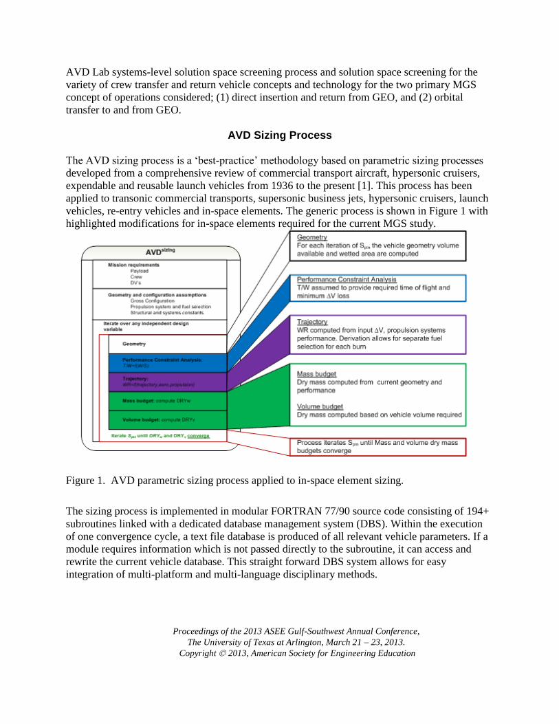
AVD Sizing Process
The AVD sizing process is a ‘best-practice’ methodology based on parametric sizing processes
developed from a comprehensive review of commercial transport aircraft, hypersonic cruisers,
expendable and reusable launch vehicles from 1936 to the present [1]. This process has been
applied to transonic commercial transports, supersonic business jets, hypersonic cruisers, launch
vehicles, re-entry vehicles and in-space elements. The generic process is shown in Figure 1 with
highlighted modifications for in-space elements required for the current MGS study.
Figure 1. AVD parametric sizing process applied to in-space element sizing.
The sizing process is implemented in modular FORTRAN 77/90 source code consisting of 194+
subroutines linked with a dedicated database management system (DBS). Within the execution
of one convergence cycle, a text file database is produced of all relevant vehicle parameters. If a
module requires information which is not passed directly to the subroutine, it can access and
rewrite the current vehicle database. This straight forward DBS system allows for easy
integration of multi-platform and multi-language disciplinary methods.

Proceedings of the 2013 ASEE Gulf-Southwest Annual Conference,
The University of Texas at Arlington, March 21 – 23, 2013.
Copyright 2013, American Society for Engineering Education
The final piece of this process is the Aerospace Sizing Disciplinary Methods Library. This
library consists of 70+ documented and implemented methods for geometry, aerodynamics,
propulsion, mass and balance, performance, etc. This library serves as quick reference for each
method’s assumptions, application, and Input-Analysis-Output (I-A-O). This library is not a
static document. The Methods Library is used to document experience with disciplinary
methods, including accuracy, runtime, and additional applicability discovered. The result is a
living document to communicate design and disciplinary experience that allows for correct usage
of disciplinary analysis. Together, the generic convergence logic, modular implementation, and
dedicated methods library allow for timely parametric sizing to address early design stage
solution space screening and decision making.
Concept of Operations Descriptions
Team 2 explored two primary ConOps for MGS crew transportation to and from GEO. The
minimum mass and complexity ConOp 1 consists of a crew capsule directly launched and
returned from GEO is considered. The second is a reusable transfer system ConOp 2 utilizes a
refuelable AOTV which transfers crew from LEO to GEO.
It is a focus of the current study to place all launch activities in the context of a production or
near-production vehicle, notably the Delta IV class of rockets. This choice of launch vehicle
constrains the diameter of all payloads launched to 5 m [13] and, along with the upper-stage
propulsion module selected, defines the maximum payload insertion mass.
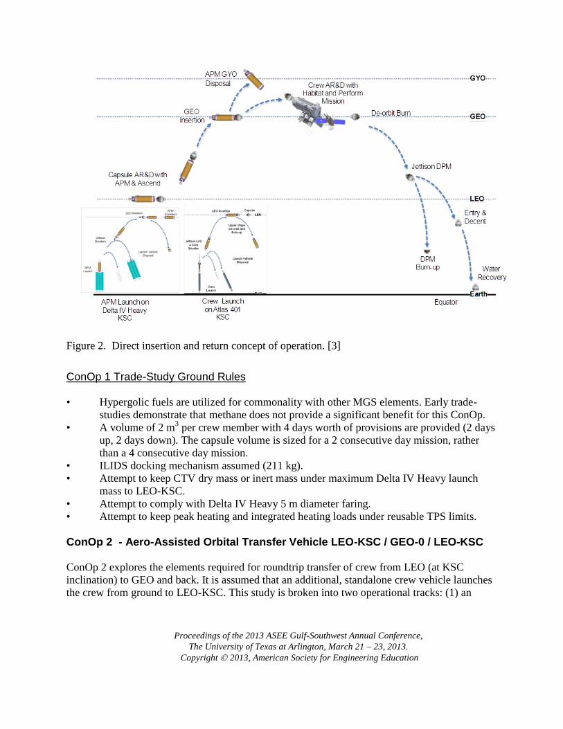
ConOp 1 - Direct Return Capsule Results This ConOp is intended to be the minimum mass, minimum complexity mission. The upper stage
of the launcher inserts the crew capsule + expendable descent module to GEO. After completion
of the servicing mission, the descent module then transfers the crew to a direct reentry return. As
such, this ConOp requires three in-space elements: (1) an expendable upper stage for insertion
into GEO, (2) a crew capsule, and (3) an expendable de-orbit propulsion module (DPM). The
study of ConOp 1 includes two primary components: (1) parametric capsule definition based on
historical review, and (2) generic capsule and DPM sizing to the specific MGS mission.
Proceedings of the 2013 ASEE Gulf-Southwest Annual Conference,
The University of Texas at Arlington, March 21 – 23, 2013.
Copyright 2013, American Society for Engineering Education
Figure 2. Direct insertion and return concept of operation. [3]
ConOp 1 Trade-Study Ground Rules • Hypergolic fuels are utilized for commonality with other MGS elements. Early trade-
studies demonstrate that methane does not provide a significant benefit for this ConOp.
• A volume of 2 m3 per crew member with 4 days worth of provisions are provided (2 days
up, 2 days down). The capsule volume is sized for a 2 consecutive day mission, rather
than a 4 consecutive day mission.
• ILIDS docking mechanism assumed (211 kg).
• Attempt to keep CTV dry mass or inert mass under maximum Delta IV Heavy launch
mass to LEO-KSC.
• Attempt to comply with Delta IV Heavy 5 m diameter faring.
• Attempt to keep peak heating and integrated heating loads under reusable TPS limits.
ConOp 2 - Aero-Assisted Orbital Transfer Vehicle LEO-KSC / GEO-0 / LEO-KSC
ConOp 2 explores the elements required for roundtrip transfer of crew from LEO (at KSC
inclination) to GEO and back. It is assumed that an additional, standalone crew vehicle launches
the crew from ground to LEO-KSC. This study is broken into two operational tracks: (1) an

Proceedings of the 2013 ASEE Gulf-Southwest Annual Conference,
The University of Texas at Arlington, March 21 – 23, 2013.
Copyright 2013, American Society for Engineering Education
expendable Ascent Propulsion Module (APM) and (2) a reusable APM. Figure 3 represents an
operational concept diagram for ConOp 2. It should be noted that a pure propulsive variant of
ConOp 2 is included as the baseline for comparison with aerobraking concepts.
Expendable Ascent Propulsion Module
For this ConOp 2 branch, the expendable APM is launched, docked with the crew vehicle, and
then transfers and inserts the crew vehicle to GEO before being discarded. The crew vehicle’s
integral DPM transfers the crew back to GTO, an aerobrake maneuver is accomplished with the
AOTV structure, and a small LEO insertion burn is performed to return the crew to LEO (except
in the pure propulsive case where propellant is utilized in place of the aeromanuever to complete
LEO insertion). A commercial crew return vehicle is then required to dock with the AOTV for
crew return to Earth.
Figure 3. LEO insertion, orbital transfer to/from GEO, LEO return concept of operation. [3]
Reusable Ascent Propulsion Module Hydrogen is utilized for the APM to reduce the fuel mass required to reach GTO. The DPM uses
hydrogen for the GEO insertion burn (stored in drop tanks) and then uses methane for the de-
orbit, plane change, and LEO circularization burns, requiring a dual-fuel LH2/CH4 Engine. The

Proceedings of the 2013 ASEE Gulf-Southwest Annual Conference,
The University of Texas at Arlington, March 21 – 23, 2013.
Copyright 2013, American Society for Engineering Education
APM will separate from the payload and DPM at GEO, autonomously perform an atmospheric
pass to reduce orbital altitude, and re-circularize at LEO to be used for future missions.
ConOp 2 Trade-Study Ground Rules • A volume of 2 m
3 per crew member with 4 days’ worth of provisions is provided (2 days
up, 2 days down). Early studies show that greater crew volume results in an excessive
mass penalty. Thus, the capsule volume is sized for a 2 consecutive day mission, rather
than the 4 consecutive day mission.
• ILIDS docking mechanism assumed (211 kg).
• Attempt to keep CTV dry or inert mass under maximum Delta IV Heavy launch mass to
LEO-KSC.
• Attempt to comply with Delta IV Heavy 5 m diameter faring.
• Attempt to keep peak heating and integrated heating loads under reusable TPS limits.
Vehicle Concept Description
In order to apply the sizing process described in Section II to the specific mission and vehicle
combinations in Section III, an analytic description of the geometry and weight of each vehicle
element is needed. A literature review of established space vehicle projects pertaining to the
vehicle elements required for MGS establishes a database and knowledge-base that is the basis
for all vehicle and architecture sizing activities presented.
Capsule The capsule utilized for the minimum-complexity ConOp 1 demands parametric geometry and
mass descriptions. Figure 4 shows the capsule geometry parameterization consisting of a
spherical cap connected to a conical frustram, Equations 1-6 derive the geometric relations of the
needed parameters to the overall diameter of the capsule, and Table 1 shows the non-dimensional
values assumed based on reference vehicles [4]. The TPS configuration of a capsule involves a
high-temperature ablative material located on the windward spherical cap, whereas the leeward
conical frustram features a low-temperature ceramic tile TPS, both of which are high-maturity
technologies. It is shown from both theory and practice that the mass of TPS per surface area
remains relatively constant for capsules [4], therefore areal weights are assumed constant for
current TPS technologies as well as for structural support. All areal weight values assumed are
shown in Table 2.

Proceedings of the 2013 ASEE Gulf-Southwest Annual Conference,
The University of Texas at Arlington, March 21 – 23, 2013.
Copyright 2013, American Society for Engineering Education
Figure 4. Geometry parameterization of generic re-entry capsule.
1) (
⁄)
2) ⁄
⁄
( )
3)
⁄
⁄
⁄
4) ⁄
⁄ ⁄
5)
⁄ (
⁄
)√(
⁄ (
⁄ )
) (
⁄ )
6)
ψ
D1D2
RN
L
Ls Lc

Proceedings of the 2013 ASEE Gulf-Southwest Annual Conference,
The University of Texas at Arlington, March 21 – 23, 2013.
Copyright 2013, American Society for Engineering Education
Table 1. Capsule geometry relations
Geometry Value
RN/D1 1.20
L/D1 .65
D2/D1 .30
Ψ 24.70°
Table 2. Capsule areal weights
Component UNW,
kg/m2
Ablator TPS 6.59
Tile TPS
Average TPS
8.98
8.04
Structure [5] 24.40
All-Propulsive OTV As a baseline configuration for ConOp 2, an all-propulsive OTV is established in order to assess
the delta- improvement in propellant mass of an aerobraking OTV. The mass of the all-
propulsive OTV is dominated by the propellant mass as a direct result of the ∆V budget allotted
for the mission.
Aerobraking OTV’s Aerobraking vehicles are subject to a demanding aero-thermal environment, and to ensure both
the physical and logistical feasibility of vehicle and architecture designs, constraints are
implemented into both the computational sizing process and the off-line analysis. The aero-
thermal constraints considered for the MGS study are: (1) wake impingement heating, and (2)
stagnation point nose heating.
Wake Impingement Heating

Proceedings of the 2013 ASEE Gulf-Southwest Annual Conference,
The University of Texas at Arlington, March 21 – 23, 2013.
Copyright 2013, American Society for Engineering Education
Figure 5. Wake impingement angle versus angle of attack for open aerobrake vehicles [8]
Afterbody heating is a major consideration in the TPS layout development of OTV concepts.
Past studies have shown that in open aerobrake structures (deployable and raked cone aerobrake
vehicles), the angle between the edge of the forebody structure and the area of increased heating
is a known function of angle of attack (Fig. 12). By implementing this impingement angle as an
active constraint on the vehicle layout, the aerobrake geometry can be sized such that the payload
and systems located behind the main aerobrake structure do not require a high-temperature, high-
density TPS.
Stagnation Point Nose Heating Stagnation point heating at the nose of a re-entry vehicle governs the TPS material required,
which in turn affects the reusability and weight of the vehicle system. As a first order
approximation, an empirical relation between ballistic coefficient, hypersonic L/D, nose radius,
and stagnation point heat transfer rate has been developed for aerobraking vehicles [7]. This
relationship has been utilized to identify areas of unreasonable heating environments within the
vehicle trade space. In the context of equation 7, maximum heating rate is known as a function of
TPS material selected, while the ballistic coefficient and hypersonic L/D are determined from the
geometry/mission definition of the vehicle. Equation 7 then yields the minimum feasible nose
radius for a given combination of vehicle configuration and technology.
√ ( ) (
)
[ √
]

Proceedings of the 2013 ASEE Gulf-Southwest Annual Conference,
The University of Texas at Arlington, March 21 – 23, 2013.
Copyright 2013, American Society for Engineering Education
Off-line, Team 2 hypersonic aerothermodynamic analysts at NASA Johnson performed
computational mission-specific trajectory and heating simulations. This information was
incorporated into the sizing knowledge-base and led to more accurate TPS material requirements
and overall vehicle mass estimates.
AOTV Concepts
Figure 6. Relative performance of aerobraking and re-entry vehicle concepts (modified from [6])
Aerobraking performance is governed by the ballistic coefficient [β], defined as the mass of the
vehicle divided by the product of the drag coefficient and the reference area, and the hypersonic
L/D. As β decreases, the greater deceleration the vehicle will encounter when passing through
the atmosphere and as L/D increases, control authority improves, as does the ability to perform a
propellant-free plane change maneuver during the atmospheric pass as shown in Figure 5. The
current project involves three distinct aerobraking OTV concepts that allow for a range of
performance to be quantified into a trade space by overall vehicle size and weight. The concepts,
from low to high performance: (1) deployable symmetric aerobrake, (2) raked cone aerobrake,
and (3) COBRA ellipsled aerobrake.
Deployable Symmetric Aerobrake
0 30103
BICONIC
APOLLO
ELLIPSLED
PLANE CHANGE FROM GEO (DEG)
CROSS RANGE (NM)
MAX LIFT-TO-DRAG
RATIO (L/D)
RAKED CONE
REENTRYDECELERATION
(g’s)
SYMMETRIC

Proceedings of the 2013 ASEE Gulf-Southwest Annual Conference,
The University of Texas at Arlington, March 21 – 23, 2013.
Copyright 2013, American Society for Engineering Education
Figure 7. Symmetric aerobrake geometry [6]
Figure 8. Parametric mass breakdown of deployable aerobrake [8, 9]
The first vehicle concept is the axis-symmetric conical aerobrake, which has the lowest
aerodynamic performance (hypersonic L/D of approximately .12). The classical geometric shape
has been well-studied theoretically, in hypersonic wind tunnels, and in production research
spacecraft [7] (i.e., the Stardust and Hayabusa re-entry capsules). The axis-symmetric geometry
shown in Figure 6, utilizes an operational scheme for in-space deployment of a portion of the
aerobraking structure [8,9]. This concept has a flexible, TPS-supported, deployable outer
substructure that is opened like an umbrella prior to the aeromanuever. By confining the rigid
Proceedings of the 2013 ASEE Gulf-Southwest Annual Conference,
The University of Texas at Arlington, March 21 – 23, 2013.
Copyright 2013, American Society for Engineering Education
structure and TPS to only the centermost section of the aerobrake, this deployable structural
configuration lessens the launch vehicle diameter constraints as well as reducing heating
environments by increasing the allowable planform area of the aerobrake. Figure 7 shows a
parametric assessment of structure and TPS areal masses derived from a data-base of deployable
symmetric aerobrake concepts.
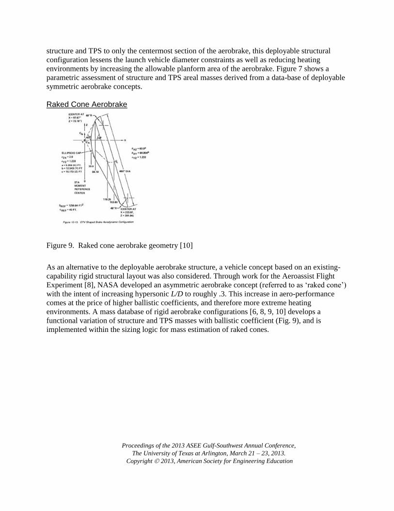
Raked Cone Aerobrake
Figure 9. Raked cone aerobrake geometry [10]
As an alternative to the deployable aerobrake structure, a vehicle concept based on an existing-
capability rigid structural layout was also considered. Through work for the Aeroassist Flight
Experiment [8], NASA developed an asymmetric aerobrake concept (referred to as ‘raked cone’)
with the intent of increasing hypersonic L/D to roughly .3. This increase in aero-performance
comes at the price of higher ballistic coefficients, and therefore more extreme heating
environments. A mass database of rigid aerobrake configurations [6, 8, 9, 10] develops a
functional variation of structure and TPS masses with ballistic coefficient (Fig. 9), and is
implemented within the sizing logic for mass estimation of raked cones.

Proceedings of the 2013 ASEE Gulf-Southwest Annual Conference,
The University of Texas at Arlington, March 21 – 23, 2013.
Copyright 2013, American Society for Engineering Education
Figure 10. Parametric mass breakdown of raked cone aerobrake [6, 8, 9, 10]
COBRA Ellipsled Aerobrake
Figure 11. Ellipsled geometry [11]
The highest performance (hypersonic L/D of .5) aerobrake considered is the COBRA Ellipsled.
This vehicle configuration is an enclosed aeroshell and therefore does not have a wake
impingement constraint for protecting the payload. Because of this, the ellipsled aerobrake shows
the potential to have the smallest cross-sectional diameter, allowing for easier launch packaging.
However, this vehicle concept has increased TPS and structure areal mass densities, resulting in

Proceedings of the 2013 ASEE Gulf-Southwest Annual Conference,
The University of Texas at Arlington, March 21 – 23, 2013.
Copyright 2013, American Society for Engineering Education
higher ballistic coefficients. The geometry required for an MGS payload results in smaller
relative nose radii, producing extreme heating environments that exceed reusable TPS levels.
The configuration may hold merit for design payloads with a volume requirement exceeding that
of MGS; increase in vehicle size, relaxes the aeroheating constraint. The aeroshell definition and
subsequent performance and mass estimates are based on the COBRA Ellipsled series of vehicle
publications [11, 12].
Figure 12. Parametric mass breakdown of ellipsled aerobrake [11]
Solution Space Visualization
Conop 1 – Direct Insertion/Reentry
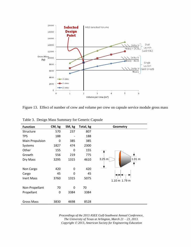
The parametric generic capsule is utilized to explore the effect of number of crew and volume
per crew on the size of an MGS Capsule. Figure 13 compares two-, three-, and four-crew
capsules with varying crew volume. Passive gross mass constraints corresponding to Delta IV-
Heavy maximum launch mass, Delta-IV Heavy with ACES upper stage, and dual launch Delta
IV heavy with a delta cryogenic second stage (DCSS) ascent propulsion module for transfer from
LEO-GEO are plotted in the trade space.
The selected MGS design point allows for three crew members with 2 m3 allocated per crew
member. The three-crew configuration was selected as the minimum required to perform the
MGS mission (Team 3), and 2 m3 per crew was determined acceptable for a two day trip going
and two day trip back from GEO. As a result, this design point allows for two launch options: (1)
dual launch of an existing Delta-IV Heavy, and (2) a single launch with a proposed Delta-IV
Heavy with ACES. Table 3 summarizes the mass breakdown for this design point.
Proceedings of the 2013 ASEE Gulf-Southwest Annual Conference,
The University of Texas at Arlington, March 21 – 23, 2013.
Copyright 2013, American Society for Engineering Education
Figure 13. Effect of number of crew and volume per crew on capsule service module gross mass
Table 3. Design Mass Summary for Generic Capsule
Function CM, kg SM, kg Total, kg Geometry
Structure 570 237 807
TPS 188 - 188
Main Propulsion 0 385 385
Systems 1827 474 2300
Other 155 0 155
Growth 556 219 775
Dry Mass 3295 1315 4610
Non Cargo 420 0 420
Cargo 45 0 45
Inert Mass 3760 1315 5075
Non-Propellant 70 0 70
Propellant 0 3384 3384
Gross Mass 3830 4698 8528
1.79 m1.10 m
3.25 m 1.01 m

Proceedings of the 2013 ASEE Gulf-Southwest Annual Conference,
The University of Texas at Arlington, March 21 – 23, 2013.
Copyright 2013, American Society for Engineering Education
Summary of Results and Recommendations
The direct entry capsule represents the simplest ConOp explored for this study,
1. Crew volume and number of crew are primary drivers in the scale of the capsule.
2. MGS generic capsule shows feasibility with current Delta IV-Heavy launch vehicle
Conop 2 – Expendable Ascent Propulsion Module
Figure 14. Geometric summary of OTV concepts – Expendable APM
For the Expendable APM branch of ConOp 2, five orbital transfer vehicle configurations are
traded: (1) Deployable Aerobrake, (2) Raked Cone Aerobrake, (3) Minimum Diameter Raked
Cone Aerobrake, (4) Ellipsled Aerobrake, and (5) Pure Propulsive Orbital Transfer Vehicle
Proceedings of the 2013 ASEE Gulf-Southwest Annual Conference,
The University of Texas at Arlington, March 21 – 23, 2013.
Copyright 2013, American Society for Engineering Education
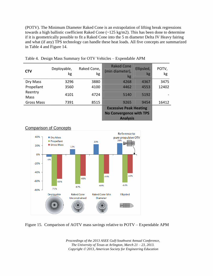
(POTV). The Minimum Diameter Raked Cone is an extrapolation of lifting break regressions
towards a high ballistic coefficient Raked Cone (~125 kg/m2). This has been done to determine
if it is geometrically possible to fit a Raked Cone into the 5 m diameter Delta IV Heavy fairing
and what (if any) TPS technology can handle these heat loads. All five concepts are summarized
in Table 4 and Figure 14.
Table 4. Design Mass Summary for OTV Vehicles – Expendable APM
CTV Deployable,
kg Raked Cone,
kg
Raked Cone (min diameter),
kg
Ellipsled, kg
POTV, kg
Dry Mass 3296 3880 4268 4367 3475
Propellant 3560 4100 4462 4553 12402 Reentry Mass
4101 4724 5140 5192 -
Gross Mass 7391 8515 9265 9454 16412
Excessive Peak Heating No Convergence with TPS
Analysis
Comparison of Concepts
Figure 15. Comparison of AOTV mass savings relative to POTV – Expendable APM

Proceedings of the 2013 ASEE Gulf-Southwest Annual Conference,
The University of Texas at Arlington, March 21 – 23, 2013.
Copyright 2013, American Society for Engineering Education
In general, all converged AOTV concepts show promise for significant mass savings over the
pure propulsive OTV. Figure 15 compares all four AOTV concepts to the pure propulsive OTV.
The Deployable aerobrake shows the greatest propellant and dry mass savings with the Raked
Cone showing similar propellant mass savings. Although the Raked Cone (Minimum Diameter)
and Ellipsled also show mass savings, later aero-thermal analysis demonstrates that these
solutions are not viable for reusable TPS due to peak heating loads. In addition, the Minimum
Diameter Raked Cone still could not meet the 4.57 m constraint from Delta IV Heavy 5 m faring.
Therefore, the unconstrained Raked Cone is suggested for further study, requiring some
assembly in-space, or modification to the Delta-IV Heavy 5 meter fairing.
All things considered, AOTVs (Deployable or Raked Cone) show promise for this ConOp.
Further study is required to select between the lighter but possibly less-durable Deployable
AOTV, and the rigid, in-space assembled Raked Cone AOTV.
Conop 2 – Reusable Ascent Propulsion Module Element mass estimation for ConOp 2 requires that DPM concepts be sized first, and then APM
concepts can be sized based on the required up-mass of the entire system. Because several
concepts for both the DPM and APM are considered, a matrix of possible architecture solutions
is obtained.
Descent Propulsion Module For this trade of ConOp 2, three OTV configurations are explored as possible descent propulsion
module options in Table 5 and Figure 16: (1) Deployable, (2) Raked Cone, and (3) Pure
Propulsive. The Minimum Diameter Raked Cone and COBRA Ellipsled have been excluded
based on the results from the Expendable APM study, which concludes that these vehicles are
impractical due to aero-thermal and small body radii considerations.
Table 5. Design Mass Summary for DPM OTVs – Reusable APM
CTV Deployable, kg Raked Cone, kg POTV, kg
Dry Mass 4846 5713 5009 Propellant 9345 10871 23263 Reentry Mass 5381 6267 -
Gross Mass 14725 17120 28807

Proceedings of the 2013 ASEE Gulf-Southwest Annual Conference,
The University of Texas at Arlington, March 21 – 23, 2013.
Copyright 2013, American Society for Engineering Education
Figure 16. Geometry summary of OTV DPM concepts – Reusable APM
Comparison of DPM Concepts As with the Expendable APM trade, the larger GEO insertion DPM benefits greatly from the
AOTV concept in terms of propellant mass (Figure 17). The rigid Raked Cone structure results
in an increased dry mass relative to the Pure Propulsive AOTV; however, the reduction in
propellant mass more than compensates. Overall, the AOTV concepts show significant gross
mass reduction which will allow for decreased propellant and dry mass of the reusable APM.
Ascent Propulsion Module For this trade, four APM OTV configurations are explored: (1) Deployable, (2) Raked Cone, (3)
Ellipsled, and (4) Pure Propulsive. The Ellipsled AOTV is reintroduced in this study because the
increased propellant volume of LH2 and staging of payload (DPM) prior to aeropass reduces the
ballistic coefficient and increases the body radii relative to the crew DPM from the Expendable
Proceedings of the 2013 ASEE Gulf-Southwest Annual Conference,
The University of Texas at Arlington, March 21 – 23, 2013.
Copyright 2013, American Society for Engineering Education
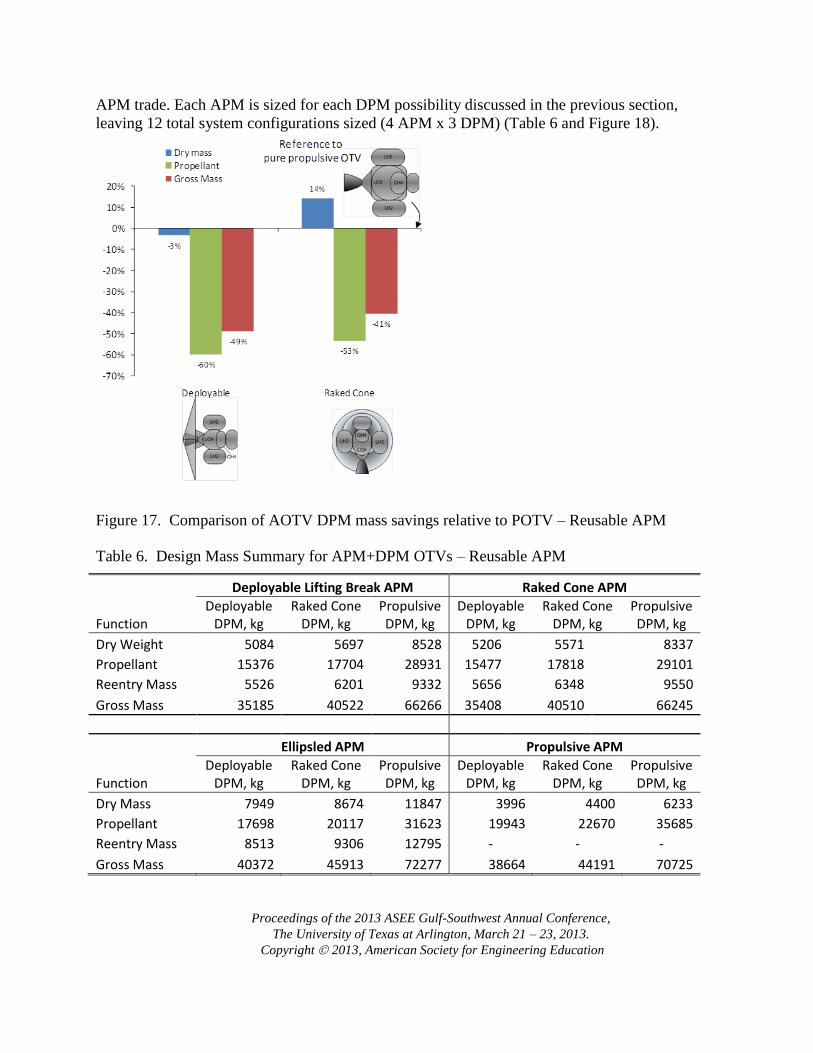
APM trade. Each APM is sized for each DPM possibility discussed in the previous section,
leaving 12 total system configurations sized (4 APM x 3 DPM) (Table 6 and Figure 18).
Figure 17. Comparison of AOTV DPM mass savings relative to POTV – Reusable APM
Table 6. Design Mass Summary for APM+DPM OTVs – Reusable APM
Deployable Lifting Break APM Raked Cone APM
Function Deployable
DPM, kg Raked Cone
DPM, kg Propulsive DPM, kg
Deployable DPM, kg
Raked Cone DPM, kg
Propulsive DPM, kg
Dry Weight 5084 5697 8528 5206 5571 8337
Propellant 15376 17704 28931 15477 17818 29101
Reentry Mass 5526 6201 9332 5656 6348 9550
Gross Mass 35185 40522 66266 35408 40510 66245
Ellipsled APM Propulsive APM
Function Deployable
DPM, kg Raked Cone
DPM, kg Propulsive DPM, kg
Deployable DPM, kg
Raked Cone DPM, kg
Propulsive DPM, kg
Dry Mass 7949 8674 11847 3996 4400 6233
Propellant 17698 20117 31623 19943 22670 35685
Reentry Mass 8513 9306 12795 - - -
Gross Mass 40372 45913 72277 38664 44191 70725

Proceedings of the 2013 ASEE Gulf-Southwest Annual Conference,
The University of Texas at Arlington, March 21 – 23, 2013.
Copyright 2013, American Society for Engineering Education
Figure 18. Geometry summary of OTV DPM+APM concepts – Reusable APM
When comparing the dry, propellant, and gross masses of the total APM+DPM system, it is clear
that the primary driver for the AOTV DPM is the reduced total propellant mass, with the
secondary driver being the APM concept (Figure 19). The selection of a Deployable or Raked
Cone DPM results in roughly a 50 to 60% propellant reduction relative to the all propulsive
systems, with the selection of the APM only having a 10 to 20% effect on the total propellant
mass over its corresponding all propulsive concept.

Proceedings of the 2013 ASEE Gulf-Southwest Annual Conference,
The University of Texas at Arlington, March 21 – 23, 2013.
Copyright 2013, American Society for Engineering Education
Figure 19. Comparison of 12 DPM+APM concepts relative to propulsive DPM+APM
The Reusable APM and DPM variation from ConOp 2 shows that the Deployable or Raked Cone
DPM concepts will provide similar propellant mass, while the Raked Cone dry mass is 10%
heavier due to the rigid structure and higher ballistic coefficient. The APM can certainly benefit
from an AOTV concept, however, the selection between AOTV concepts must come from
metrics other than mass alone. From this standpoint, all AOTV APM and DPM concepts could
provide an operational benefit with a sufficiently high flight rate and low maintenance costs.
Such cost comparison is beyond the scope of this study, but is required for realistic comparison
between reusable and expendable crew transfer architectures.
Summary of Results and Recommendations for ConOp 2
Expendable APM Trade:
1. Deployable and Raked Cone aerobrake concepts show promise for reducing propellant
mass in the crew return vehicle for return from GEO-0 to LEO-KSC.
2. Minimum Diameter Raked Cone and Ellipsled concepts present a reusable TPS material
problem due to their high ballistic coefficient and small radii.
Reusable APM Trade:
1. APM concepts sized for LEO - GTO transfer with Deployable DPM.
2. The staging of the DPM results in a significant reduction in mass at LEO circularization.
Thus, the pure propulsive OTV APM is not as severely penalized as the POTV DPM,
which must return the SBCM. As such, use of an AOTV shows less mass-reduction
Proceedings of the 2013 ASEE Gulf-Southwest Annual Conference,
The University of Texas at Arlington, March 21 – 23, 2013.
Copyright 2013, American Society for Engineering Education
potential in APMs than in DPMs.
3. The Ellipsled has a greater TPS wetted area relative to the Deployable and Raked Cone
concepts. This attribute along with the increased volume required to store the LH2
propellant results in a significant increase in dry mass over the propulsive OTV. As a
consequence, propellant savings over the baseline is reduced to only 7 % for the
Ellipsled.
Summary and Conclusions
The results from the ConOp 1 study show that a Capsule+DPM designed for MGS is
technologically feasible and of a size comparable with past and proposed capsules. Current
launch capability allows for an MGS architecture under this concept of operations.
ConOp 2 has two branches: (1) Expendable APM and (2) Reusable APM. In both branches the
AOTV DPM shows significant propellant mass savings. Overall, the selection between AOTV
concepts and reusable/expendable APM must come from consideration of their
maintenance/durability and cost of operation with an associated flight rate. Based on mass alone,
the expendable system will always demonstrate lower propellant mass per mission. Reusability is
appealing only if the flight rate such that the propellant and maintenance costs of the reusable
system under-bid the launching of an expendable APM each mission.
For both ConOp 1 and 2, if the flight rate to GEO is low, an expendable launcher and DPM with
a direct reentry capsule will show the lowest mass and complexity per mission. This conclusion
holds unless the flight rate is high enough to benefit from a more complex reusable architecture.
Acknowledgments
The authors would like to acknowledge Jeff Cerro (NASA Langley - Vehicle Analysis Branch)
for providing guidance as team lead for the study.
References
1. Coleman, G., Aircraft Conceptual Design – An Adaptable Parametric Sizing Methodology, University of Texas
at Arlington, 2010.
2. Czysz, P., HYPERSONIC CONVERGENCE: Volumes 1 through 10, Saint Louis University, Parks College,
Aerospace Engineering Dept: Course AE-P493-50 1992-93 and Purdue University Short Course "Integration of
Winged Flight Vehicles" , 1989. AE-P493-50
3. Anon., Manned Geosynchronous Earth Orbit (GEO) Servicing (MGS) Joint NASA/DARPA Study – Final
Report
4. Anon., NASA Exploration Systems Architecture Study, 2005, NASA-TM-2005-214062
5. Heinemann, W., Design Mass Properties II, Mass Estimating and Forecasting for Aerospace Vehicles Based on
Historical DATA, National Aeronautics and Space Administration, Lyndon B. Johnson Space Center, Houston,
Texas, 1994. JSC-26098
6. Anon., Space Transfer Vehicle Concepts and Requirements Study – Volume II, Book 1 Final Report – Concept
Definition and Evaluation. Boeing Aerospace Company for NASA, 1991. NAS8-37855

Proceedings of the 2013 ASEE Gulf-Southwest Annual Conference,
The University of Texas at Arlington, March 21 – 23, 2013.
Copyright 2013, American Society for Engineering Education
7. Scott et al., Design Study of an Integrated Aerobraking Orbital Transfer Vehicle, 1985. TM-58264
8. Anon., Orbital Transfer Vehicle Concept Definition and Systems Analysis Study, Executive Summary
Supplement, 1986. Martin Marietta for NASA, 1986. NAS8-36108
9. Anon., Space Transfer Vehicle Concepts and Requirements Study – Volume II, Book 1-2. Martin Marietta for
NASA, 1991. NAS8-37856
10. Anon., Orbital Transfer Vehicle Concept Definition and Systems Analysis Study, Final Report – Phase 1,
Volume II, Book 3 - Configuration and Subsystem and Trade Studies. Boeing Aerospace Company for NASA,
1986. NAS8-36107
11. Garcia et al., Co-Optimization of Mid Lift to Drag Vehicle Concepts for Mars Atmospheric Entry, 2010. AIAA-
2010-5052
12. Lafluear and Cerimele, Angle of Attack Modulation for Mars Reentry, 2009. AIAA 2009-5611
13. Isakowitz, Hopkins, Hopkins Jr., International Reference Guide to Space Launch Systems. ISBN 1-56347-591-
X
Lex Gonzalez
Mr. Gonzalez currently serves as a graduate research assistant at the University of Texas at Arlington
Gary Coleman
Dr. Coleman currently serves as a Mechanical Engineer at RSG AeroDesign
Eric Haney
Mr. Haney currently serves as a graduate research assistant at the University of Texas at Arlington
Amit Oza
Mr. Oza currently serves as a graduate research assistant at the University of Texas at Arlington
Vincent Ricketts
Mr. Ricketts currently serves as a graduate research assistant at the University of Texas at Arlington
Bernd Chudoba
Dr. Chudoba currently serves as an Assistant Professor of Aerospace Engineering at the University of Texas at
Arlington
Paul Czsyz
Mr. Czysz currently serves as a consultant through Hypertech Concepts LLC