concept study of the computer-aided artep production
TRANSCRIPT
7 7_ . .
Research Report 1403
Concept Study of theComputer-Aided ARTEP Production System (CAPS)
If) G. W. Bloedorn, W. H. Crooks, M. D. Merrill, H. J. Saal0') Perceptronics, Inc.
* 0 1. L. Meliza and 0. 1. KahnSARI Field Unit at Presidio of Monterey, California
ARI Field Unit at Presidio of Monterey, California
Training Research Laboratory
D T2E t
j3] UG 9 -3
6- U. S. Army
Research Institute for the Behavioral and Social Sciences
July 1985
Approved for public release; distribution unlimited.
86

UNCLASSIFIEDSECURITY CLASSIFICATION OF THIS PAGE (".. [)of. Fr-,ed)
READ INSTRUCTIONSREPORT DOCUMENTATION PAGE BEFORE COMPLETING FORM1. REPORT NUMBER 2. GOVT ACCESSION NO. 3. RECIPIENT'S CATALOG NUMBER
ARI Research Report 1403 co;. -7 _______________
4. TITLE (and Subtitle) S. TYPE OF REPORT & PERIOD COVEREDFinal Report
CONCEPT STUDY OF THE COMPUTER-AIDED ARTEP September 1984-May 1985PRODUCTION SYSTEM (CAPS) 6. PERFORMING ORG. REPORT NUMBER
7. AUTHOR(.) a. CONTRACT OR GRANT NUMBER(&)
Bloedorn, G. W., Crooks, W. H., Merrill, M. D., &Saal, H. J. (Perceptronics); & Meliza, L. L., & DABT60-84-C-0109Kahn, 0. 1. (ARI)
9. PERFORMING ORGANIZATION NAME AND ADDRESS 10. PROGRAM ELEMENT. PROJECT, TASK
Perceptronics, Inc. AREA 6 WORK UNIT NUMBERS
6271 Variel Avenue 2Q263743A794Woodland Hills, CA 91367 4311 100
11. CONTROLLING OFFICE NAME AND ADDRESS 12. REPORT DATE
ARI Field Unit July 1985P.O. Box 5787 13. NUMBER OF PAGES
Presidio of Monterey, CA 93944-5011 17514. MONITORING AGENCY NAME & ADORESS(if different from, Controlling Office) 1S. SECURITY CLASS. (of this report)
U.S. Army Research Institute for the Behavioraland Social Sciences Unclassi fied
5001 Eisenhower Avenue ISa. DECL ASSI FICATION/ DOWNGRADING
Alexandria, VA 22333-5600 SHDL
16. DISTRIBUTION STATEMENT (of gti Report)
Approved for public release; distribution unlimited
17. DISTRIBUTION STATEMENT (of Cho abstract ontered in Stock 20, lIdifforoe from Report)
IS. SUPPLEMENTARY NOTES
1. Contracting Officer's Representative, Otto I. Kahn.
2. Appendixes published separately.
19. KEY WORDS (Continue on revere* side if necessary and Identify by block nuvmber)
Army Training and Evaluation Program (ARTEP)
Computer-aided ARTL? Production System (CAPS)Relational data base management system
2&. ANSTRAC? (cmtha sa powwo adf N rmeneuir od iderdity by block number.)
Army service schools use typewriters and/or stand-alone word processors to
prepare Army Training and Evaluation Program (ARrEP) 6')cumernts as guides to
unit training. Requirements to periodically revise APEIEP documents to reflect
the continual changes in tactical doctrine associated with the force -moderniza-
tion effort, combined with the new requirement to pre ,,ire-improvedu ARIEP
documents containing detailed unit training plans, hav.' greatly increased the
size and complexity of the ARTEP development workload.P(Cont inued)
DD ~'I 1473 EDITION OF I NOW GS IS OBSOLETE 'c.\i .IE
i SECURITY CLASSIFICATIOPC OF THIS PAGE (When Dae. Entered)
x.. P If. 'r r. *% ~ * . ~* ~ *

UNCLASSIFIEDSI1CUOITY CLASSIFICATION OF THIS PAGE(Whon Does Entd)
ARI Research Report 1403
20. (Continued)
/ The purpose of this research was to define the concept of a Computer-aided ARTEP Production System (CAPS) for the development of a prototype sys-tem within the U.S. Army Infantry School (USAIS). The functions to beassisted by automation were defined through reviews of TRADOC guidance forpreparing' improved 'ARTEPS, TRADOC Reg 310-2 (Test), and through review ofthe ARTEP development process within USAIS. Computer technologies appropri-ate to these functions were selected from among those technologies frequentlyapplied to document preparation.
This report provides input for the selection of hardware/software for aprototype CAPS, and it aids in defining the research/development tasks re-quired to develop such a prototype.
4
UNCI.ASSIFIEDi IECUMITY CLASSIFICATION OF THIS PAGE("n ).I. P-nI.d)

U. S. ARMY RESEARCH INSTITUTE
FOR THE BEHAVIORAL AND SOCIAL SCIENCES
A Field Operating Agency under the Jurisdiction of the
Deputy Chief of Staff for Personnel
WM. DARRYL HENDERSONEDGAR M. JOHNSON COL, INTechnical Director Commanding
Research accomplished under contract forthe Department of the Army
Perceptronics, Inc.
Technical review by
Gean BiglerJean Dyer
NOTICES
DISTRIBUTION: Primary distribution of this report has been made by ARI. Please address correspondence concerning distribution of reports to: U.S. Army Research Institute for the Behavioraland Social Sciences. ATTN: PERI-POT. 5001 Eisenhower Ave., Alexandria. Virginid 22333-5600.
FINAL DISPOSITION: This report may be destroyed when it is no longer needed Please do notreturn it to the U.S. Army Research Institute for the Behavioral and Social Sciences
NOTE The findings in this report are not to be construed as an official Department of the Aim V
position, unless so designated by other authorized documents
Cl
Research Report 1403
Concept Study of theComputer-Aided ARTEP Production System (CAPS)
G. W. Bloedorn, W. H. Crooks, M. D. Merrill, H. J. SaalPerceptronics, Inc.
L. L. Meliza and 0. I. Kahn
ARI Field Unit at Presidio of Monterey, California
ARI Field Unit at Presidio of Monterey, CaliforniaJack H. Hiller, Chief
Training Research LaboratoryRobert J. Seidel, Acting Director
U.S. ARMY RESEARCH INSTITUTE FOR THE BEHAVIORAL AND SOCIAL SCIENCES5001 Eisenhower Avenue, Alexandria. Virginia 22333-5600 S
Office, Deputy Chief of Staff for Personnel
Department of the Army
July 1985
Army Project Number Education and Training20263743A794
Approved for public release; distribution unlimited.
" e'"-"%""o "- '." -" -°
°" - % °
"- " " o
" ° " " " " * " 11°
" 1

AFtI Research Reports and ecthnicdl F-lports are inten(Je(l for Sponsors ofR&D tasks and for other research anI military agencies. Any findings readyfor implementation at the time of publication are presented In the last partof the Brief. Upon completion of a malor phase of the task, formal recom-mendations for official action normally are conveyed to appropriate militaryagencies by briefing or Disposition Form.

FOREWORD
The Army Research Institute (ARI) Presidio of Monterey Field Unit is con-cerned with improving unit collective training through research and develop-
ment. One aspect of this work concerns the design and preparation of ArmyTraining and Evaluation Program (ARTEP) documents by Army service schools asguides to unit collective training. Research in this area is conducted by theCollective Training Design Team under the sponsorship of the proponent forARTEP development policy and procedures, the U.S. Army Training Board (ATB).
This report defines the concept of a Computer-aided ARTEP Production Sys-tem (CAPS) in preparation for the development of a prototype CAPS within the
U.S. Army Infantry School (USAIS). Research partners included in this effortinclude the U.S. Army Armor School (USAARMS), the U.S. Army Air Defense Artil-lery School (USAADASCH), and the U.S. Army Intelligence Center and School
(USAICS).
EDGAR M. JOHNSONTechnical Director
[ . ,.
?.'"€; 2€: 2 2'. .'.:,-,.'..'.2":'.''. €.''2. ". . . .:< 'C* ,,"* ...-..-. -.... ;-" •".-2..2-' '..-i-'.- .', -.-. '..'--'- 4-

CONCEPT STUDY OF THE COMPUTER-AIDED ARTEP PRODUCTION SYSTEM (CAPS)
EXECUTIVE SUMMARY
Requirement:
US Army service schools prepare Army Training and Evaluation Program(ARTEP) documents as guides to unit collective training. School workloads aregrowing substantially in order to effectively meet the information needs ofARTEP users. More specifically, schools must:
0 prepare "improved" ARTEP documents which effectively combine "how totrain" guidance with the "what to train" guidance traditionally
*provided by these documents;
o periodically revise ARTEP documents to reflect the continual changesin tactical doctrine associated with the ongoing process of Armyforce modernization.
The tools generally available to ARTEP developers (i.e., typewriters andstand-alone word processors) appear inadequate given the growing ARTEP
°. development workload. Therefore, the purpose of the present research was to
define the concept of a Computer-aided ARTEP Production System (CAPS) inpreparation for the development of a CAPS prototype. This research wasconducted under the sponsorship of the proponent for ARTEP development, the USArmy Training Board (ATB).
Procedure:
Phase I of this effort was concerned with identifying the type of ARTEPdevelopment functions to be facilitated by a CAPS. The process of developing"improved" ARTEP documents was studied as it is defined in TRADOC Reg 310-2(Test) and as it is practiced within the school designated to host the CAPSprototype, the US Army Infantry School (USAIS). The specific objectives ofthis phase were to:
" identify, describe and size the ARTEP-related products and interimproducts prepared by each USAIS organization involved in ARTEPdevelopment;
o identify, describe and size the source materials used in preparingeach product;
o define decisions to be made when preparing each product.
In Phase II, computer technologies which have been applied to documentpreparation were identified and critiqued in terms of their applicability tothe ARTEP development process defined in Phase I. A key issue was the type ofdata base management system (e.g., relational versus hierarchical) which isbest suited to ARTEP development.
vii

A concept of a CAPS was defined and illustrated in Phase III. Alternativelists of commercially available hardware/software compatible with the concept(i.e., and compatible with other hardware/software noted in the same list)were developed. Estimates of the research/development tasks necessary toimplement the development of a CAPS prototype were prepared.
Findings:
o ARTEP preparation requires service schools to manage what might beviewed as three interrelated data bases --
o tactical doctrine (e.g., FMs);
o training requirements (unit missions, collective tasks andindividual tasks to be trained);
o training plans.
o A given item of information within one data base may bear a number offunctional relationships to items within the other data bases and toother items within the same data base. A relational data basemanagement system would provide a flexible and concise method ofrecording these relationships.
o Estimates of the amount of data to be stored within a CAPS suggestthe need for a minicomputer.
o Approximately 50 percent of the information provided within improvedARTEP documents is in the form of figures and tables. Graphicsterminals and a printer with a high degree of graphics capabilityappear to be required elements of a CAPS. Commercially availablegraphics terminals and printers meeting CAPS specifications wereidentified.
o Ideally, the CAPS should be a menu-driven system which guides usersthrough the ARTEP development process. Such a system would reduceformal training requirements. The use of a relational data basemanagement system as the core of a CAPS greatly facilitates thedevelopment of menus, because short, standardized queries and command
statements (i.e., often a single line) replace traditional computerprogramming.
o The early phases of CAPS prototype development will be concernedwith:
o refining CAPS functional requirements (e.g., relating eachdecision made in preparing a product to specific source
materials rather than relating the product as a whole to thesematerials);
o designing the CAPS data base to effectively address refined CAPS
functional requirements.
viii
*IF 91 W. 9F - r . P .r
o writing standardized data base queries and command statementsfor extracting information required to support specific ARTEPdeveloper decisions and for loading/changing data.
Utilization of Findings:
The findings of this effort will be considered in the selection ofcommercially available hardware and software for a prototype CAPS. Thesefindings will also be employed in developing a prototype CAPS within USAIS.
ix

CONCEPT STUDY OF THE COMPUTER-AIDED ARTEP PRODUCTION SYSTEM (CAPS)
CONTENTS
Page
INTRODUCTION ........ .... ............................... . ... 1
The Problem ....... .... .............................. .i....The Solution ..................................... 2Computer-Aided ARTEP Production System (CAPS).. ...... ............. 3Objectives of the Study and Contents of the Report ..... .......... 5
ANALYSIS OF ARMY TRAINING PRODUCTS AND PROCEDURES ...... ............ 7
Introduction ......................................... 7A Systems Approach to Training ......... ...................... 7Task Relationships in Army Training ...... ................. .... 12The ARTEP Database ............ . .......................... ... 17Development of a Mission Training Plan ...... ................ ... 25Comparison of Infantry and Armor School Formats with
TRADOC Regulation 310-2 ........ ...................... ... 58US Army Infantry & Armor School MTP Development Organizations .. ..... 60Summary and Conclusion ......... ........................ ... 65
FUNCTIONAL REQUIREMENTS OF CAPS ........ .. ..................... 70
Idea Processing Requirements ....... ..................... .... 70Author- and Decision-Aiding Utilities ..... ................. .... 71Man-Machine Interface Requirements ...... ................. .... 77Database Management Requirements ....... ................... ... 87Computer System Approach (Hardware and Software) ... ........... ... 91
CAPS SYSTEM DESIGN ........ ..... ............................ 93
Data Input ........ .... .............................. ... 93CAPS User/System Interface ........ ...................... ... 98CAPS Data Representation ......... ....................... ... 120Impact Relationships ........ .. ......................... ... 129CAPS Database Management System ..... .................... 133Comparison Between Oracle and Ingres for Use as CAPS Database System 141Built-in Multiuser Design Features, Access and Concurrency Control . 142Protection Control and Authority in the CAPS System ... .......... ... 143CAPS Information Processing Design ....... .................. ... 146
ESTIMATE OF CAPS DEVELOPMENT EFFORT ....... ................... ... 153
Program Stages and Tasks ......... ....................... ... 153Estimated Manpower Requirements ....... .................... ... 154Hardware Procurement Cost Estimates ...... .................. ... 156Program Plan ....... .... ............................. ... 156
xi

LIST OF FIGURES
FIGURE # TITLE PAGE
1 Electronic Unit Training System Concept 42 Platoon Mission Training Plan 93 Individual Task-to-Mission-to-Echelon Integration 154 Individual-Collective Task Integration 165 US Army Infantry School Database Development
Organization 206 ARTEP Development/Authoring 217 ARTEP Database Workflow at the US Army Infantry
School 238 "NEW" ARTEP Contents 249 Hierarchy Plus Input-Process-Output System Analysis
for CAPS 2610 CFEA Hierarchy 2711 Develop Individual Tasks, Conditions and Standards 2812 Develop Individual Tasks, Conditions and Standards 2913 Identify Task Elements, Cues & Skills 3014 Develop T & EO 3115 Prepare a Situational Training Exercise 3216 Prepare Crew/Squad/Section and/or Platoon Drills 3317 Develop a Training Plan 3418 Identify and Produce Task Integration Matrix 3519 Develop FTX 3620 Develop the Training Matrix 3721 Develop the Unit Test 3822 Processes in the Development of the MTP 4123 Example STX: Platoon Hasty Attack 4424 Platoon Mission Training Plan 4625 Drill Diagram, with Drills Identified 4826 Training Plan Mission-Task Diagram 5527 Mission Training Plan Organization 5928 Infantry School MTP-Development Organization 6629 Armor School MTP-Development Organization 6730 CAPS User Input System 9431 CAPS User Screen 9932 CAPS User Screen - Initial State 10033 User Pull-Down Menu 10134 User Identification Dialog 10235 Improper ID. Dialog 10336 Priority Pull-Down Menu 10437 Access Control Dialog Menu 10538 New User Dialog 10639 Access Pull-Down Menu 10840 File Pull-Down Menu 109
'K - .. ii~-**-*-.- * *..* ,.,.. . ..

LIST OF FIGURES (CONT'D)
FIGURE 0 TITLE PAGE
41 Document Select Dialog Menu 11042 Open Document Window 11243 Edit Pull-Down Menu 11344 Font Dialog 11445 Pattern Mode 11546 Utilities Pull-Down Menu 11747 Help Pull-Down Menu 11848 Component Pull-Down Menu 11949 Component Selection Dialog Menu 12150 MOS (Job) x Individual (MOSxIT) Matrix 12351 Soldier's Manual x Squad Collective Task x
Individual Task (StxSCTxIT) Matrix 12452 Platoon Mission x Platoon Collective Task x
Squad Collective Tasks (PMxPCTxSCT) Matrix 12553 Company Mission x Company Collective Task x
Platoon Collective Task (CMxCCTxPCT) Matrix 12754 Battalion Mission x Battalion Collective Task
x Company Collective Task (BMxBCTxCCT) Matrix 12855 CAPS Iterative Impact Diagram 13056 A Small Relational Database 14057 Overall CAPS System Architecture 14858 Apollo WS-Based CAPS Architecture 15759 AT&T UNIX PC-Based CAPS Architecture 15960 CAPS Program Plan 161
Xiii

LIST OF TABLES
TABLE # TITLE PAGE
1 Missions Performed by Echelons 112 Task Identification Data 133 Relationships Among Army Tasks 184 Sample Training & Evaluation Outline 425 Drill Description: Wedge Formation 506 MTP Format and Organization Comparison Between
USAIS and TRADOC REG 310-2 617 Company Level MTP Format 638 Battalion Level MTP Format 649 CAPS System Development - Estimated Manpower
Requirements 15510 Cost Estimate - Apollo-Based CAPS Architecture 15811 Cost Estimate - AT&T UNIX PC-Based CAPS
Architecture 160
xiv

CONCEPT STUDY OF THECOMPUTER-AIDED ARTEP PRODUCTION SYSTEM (CAPS)
INTRODUCTION
This report is the final technical report of a six month study sponsored bythe Army Training Board and technically monitored by the Army ResearchInstitute (ARI) under Contract No. DABT60-84-C-0109 to produce a conceptualdesign for a Computer-aided ARTEP Production System (CAPS).
The Problem
Army branch service schools prepare Army Training and Evaluation Program(ARTEP) documents as guides to unit training. The ARTEP consists of amulti-echelon, integrated, combined arms training program featuring unitmissions and the collective tasks, conditions, and standards necessary formission success. It includes structured evaluation outlines intended toprovide units with data to formulate remedial training strategies.
The ARTEP development workload of each school has been increased by twoevents. First, changes in tactical doctrine associated with forcemodernization impose requirements to revise existing ARTEPs or to prepareARTEPs for new types of units. Second, the ARTEP is being transformed from adocument that merely describes unit training requiremens to one that providesdecriptive unit training plans (TRADOC Regulation 310-2. Development,preparation, and management of Army Training and Evaluation Program, January,1984). This transformation requires new types of analyses to be performed byARTEP developers, and it requires the preparation of new types of productsunder the rubric of "ARTEP." Both force modernization and ARTEP improvementadd to an already overburdened manual ARTEP production process.
Specific problems inherent in any paper and pencil system dealing with thenumber of variables addressed b-The ARTEP are:
1. The ARTEP production process is not responsive to its users nor
to its environment. As suggested above, when doctrine,tactics, and equipment are changed, the underlying tasks,conditions, and standards of performance for successful missionaccomplishment will change as well. Not only must the ARTEPcontinue to support current battlefield TO&E, but also it mustkeep pace with the programmed introduction of new systemstechnology, (e.g. Force Modernization Products), and neworganizational structures, (e.g. Division 86), as they arefielded. The current two year production cycle for thedevelopment/revision of the ARTEP cannot keep up with thesedevelopments, and thus new ARTEPs are frequently obsolete whenissued.
2. The lengthy ARTEP production process also inevitably requiresthat the responsibility for authorship of specific contentpasses through two or three hands during thedevelopment/revision cycle. While general standards for style
qI
'.;;." .'" '" "'-'.''-':, :- .., .. ... , . . . . . .- , . . . .. . . . . . . . . 1

and content do exist, it still allows for considerable latitudein quality and comprehensiveness. Thus, a document of uniformhigh quality is unlikely. Furthermore, variances in style andterminology result in misinterpretations by users.
3. ARTEP authors will normally be trainers or subject matterexperts, not professional writers or instructional developers.Many may have difficulty in producing professional leveltraining products, and all will require a period offamiliarization to become aware of the requirements of the joband the resources at hand. The training investment required tocreate a good ARTEP author must be amortized over a relativelyshort period due to normal personnel rotation cycles. Thecurrent two year development time results in a wastefuldiffusion of costly training as personnel are lost and newstaff take their places.
4. Current ARTEP documents are, for the most part, too bulky to beconveniently useful. They include training programs foreveryone, from combat arms personnel to fuel truck drivers.The result is that the document is difficult to carry to thefield and too complex for quick reference. The broad scope ofactivities included guarantees that frequent revisions will berequired, and as noted above, these take an inordinately longtime to produce. When produced, the cost of revision,printing, and distribution is unreasonably high because theunrevised material must be reissued as well.
5. The cumbersome ARTEP production and distribution processprecludes 1) ARTEP tailoring by the SME/authors to program theindividual needs of local users, and 2) timely revisions ofARTEP's in response to feedback from users.
Taken together, these deficiencies inherent in a manual ARTEP productionsystem prevent the ARTEP from realizing its full potential as a meaningfuland effective training tool for the units. Until now, technology had littleto offer to improve the situation when the constraints of cost and manpowersupport resources were considered. Recent developments in low-cost,easy-to-use distributed information processing systems, and progress indefining more precisely the process by which ARTEP missions and tasks areproduced set the stage for implementation by interactive automation.
The Solution
It is apparent that what is required are new tools, techniques, andorganizational approaches for the production of ARTEP that are (1) moreefficient, (2) more responsive, and (3) less costly than the current manualapproach. The technological bases for these developments are now realizablethrough exploitation of recent advances in:
2

o Distributed computational networks.
o Electronic information distribution.
o High performance intelligent workstations.
o Inexpensive very large scale mass storage.
o Artificial intelligence tools to assist non-expert human users.
o Advanced man-machine interaction protocols to relieve users of theburden of understanding system operation and facilitateconcentration on content rather than process.
Computer-Aided ARTEP Production System (CAPS)
CAPS will take advantage of the technologies mentioned above to provideimproved efficiency, responsiveness, and less costly production of ARTEP. Itwill support authors in the following areas:
o ARTEP database storage, query, and management.
o ARTEP authoring and revision.
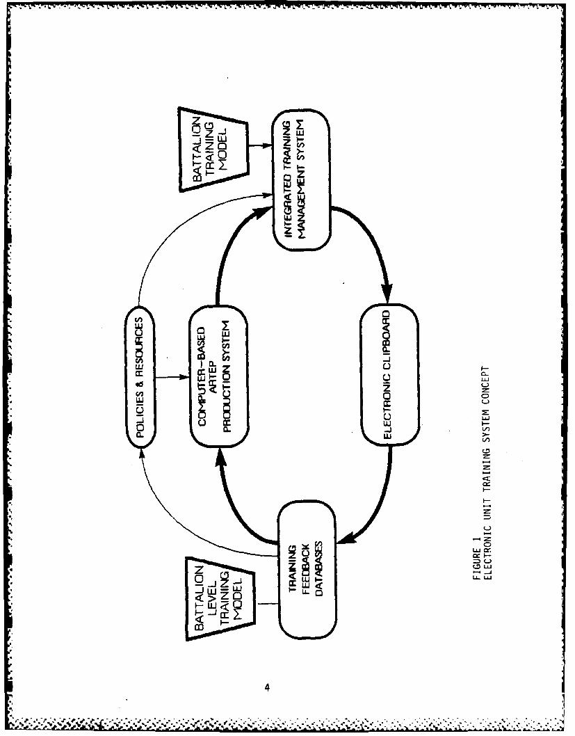
CAPS will initially support these functions on a stand-alone basis, but whenmature it is viewed as one component of a distributed training authoring,distribution, management, and evaluation network. Figure 1 presents anotional schematic of this mature system. The CAPS portion of this system isfounded on the development doctrine that makes individual authors responsiblefor specific ARTEP component products. Change authority will be restricted tothe designated sponsor for each section. Thus, the workstation topology willbe structured to parallel lines of authority for authoring and updatingresponsibility. Although in our concept, any user can review any materialresident in the system as needed, he can only revise those portions that arehis assigned responsibilities. The importance of this structure is that asthe system becomes aware of the need for ARTEP revision, work assignments canbe routed automatically to appropriate authors.
Initially, when operated in its stand-alone configuration, CAPS will producethe ARTEP (or, to use the latest terminology, ARTEP Mission Training Plans andDrills) from a standard database maintained by subject matter experts, anddistributed in paper form to end users. Eventually, when part of anelectronic distribution network such as the one illustrated in Figure 1, acurrent ARTEP can be maintained in mass storage at the ARTEP development site,and can be distributed via low bandwidth links (modem net) or via mailedmagnetic disks or tapes, as required to commanders/units. This will not onlyeliminate the need for large printed volumes in the field, but will also makeavailable to field commanders electronic access to the entire ARTEP database.The commander can then use this information to tailor his ARTEP to specificmission and location requirements.
3
A A"-% Lk?-b
00
t--J
L) L)
L) L
Z
UJ 00
CC
ui 0
LL)
) U.LIJ
4 u

Ideally, CAPS and the systems to which it is linked, will eventually becomethe mechanism for linking training resource expenditure to trainingproficiency. Such information is required to justify the acquisition oftraining resources and to support rational distribution of these resources.
In summary, the provision of shared data resources and informationdistribution throughout the ARTEP development process to support automatedproduction, updating, and distribution of products to the field will:
o Produce a better product in a more timely manner (i.e., less subjectto errors and more valid because the production process incorporatesperformance feedback as an integral part of the system).
o Establish a common database that is less sensitive to personnelturbulence within both the TRADOC school and the using unit.
o Increase the productivity of the ARTEP development team, who willalso be required (in accordance with the latest TRADOC policy) toauthor subjects they teach.
o Increase responsiveness to changes in hardware, doctrine,trainer/soldier profile, training policies, procedures, and commandguidance.
o Create a database that is useful for personnel selection, trainingevaluation of new systems, training resource acquisition anddistribution in accordance with mission priorities, and that willprovide a necessary database to support research in trainingtechnology.
o Provide training support packages rapidly to support contingency
deployments.
*Objectives of the Study and Contents of the Report
The objective of this study was to develop a concept and a design, to includenew tools, techniques, and organizational approaches, for the production ofARTEP. The aim of the automated ARTEP production system will be to provideimproved efficiency, responsiveness, and less costly production of ARTEPthrough the innovative use of interactive automation to assist in:
1. ARTEP database storage, query, and management2. ARTEP authoring and revision.
Haphazard automation is potentially a serious problem resulting in wastefulduplication of effort and/or inadequate attempts to automate funtions. ArmyRegulations 18-1, Army Automation Management, was developed to guide theapplication of automation to Army needs. The present study was conducted toestimate the hardware/software requirements for developing a prototype CAPSwithin a designated school. The present study, combined with the developmentryof a prototype, represents the concept development phase of a CAPS within the
Army Automated System Life Cycle.
5
. . . . .. . . . .]

I-
The second chapter and the Appendices describe in detail the currentstate-of-the-world with respect to ARTEP production. This chapter focusesspecifically on procedures and organization at the US Army Infantry School(USAIS) and the US Army Armor Center (USAARMC). The ARTEP database, as it Isderived and organized, is discussed, as are the various doctrinal publicationsand TRADOC regulations related to ARTEP preparation.*
The third chapter describes the functional requirements for the Computer-aidedARTEP Production System and analyzes the technologies that can be brought tobear in creating an effective CAPS system. The fourth chapter presents thedetails of the CAPS system design, including the database management system,the user interface, and the system architecture. The fifth chapter thenpresents our estimates of the program plan, the estimated manpowerrequirements, and the estimated hardware costs.
* This study was conducted with the generous cooperation and assistance from thecommanders and staff members of several TRADOC commands, including the US ArmyTraining Board, the US Army Infantry School, the US Army Armor School, and theUS Army Air Defense Artillery School.
*Chapter 2 refers to a number of Appendices relevant to the ARTEP development
process. These Appendices are contained within an ARI Research Note entitled"Appendices to Computer-aided ARTEP Production System (CAPS) Concept Study".
6d
6
, . . .-*-,;p , " #', - - .- ,, . .-* • ; . , . , -. , . . - ... -,. , .. , - , - ..*

ANALYSIS OF ARMY TRAINING PRODUCTS AND PROCEDURES
Introduction
The Army Training and Evaluation Program (ARTEP) is a collection of trainingguidance to coiwanders and trainers in the field that identifies (1) combatcritical tasks, (2) realistic battlefield conditions under which the tasksmust be performed, and (3) minimum standards of performance. The ARTEP alsoprovides a framework for commanders and trainers to develop their owneffective individual and unit training and evaluation programs. Finally, theARTEP (1) provides guidance that facilitates evaluation of unit trainingprograms and individual and collective training proficiency, and (2)facilitates identification of training deficiencies to allow development andconduct of remedial training.
While other portions of the ARTEP identify skills that must be trained, theARTEP Mission Training Plan (AMTP) provides guidance to assist the trainer indetermining how to train to specific standards within the ARTEP framework of acombined arms--orce in a tactical situation, i.e., Mission, Enemy, Troops,Terrain, and Time (METT-T).
Changes to the current ARTEP, embodied in TRADOC test regulations, intend theterm "ARTEP" to encompass the entire body of Army training literature. Thecurrent ARTEP will be restructured and renamed the "ARTEP Mission TrainingPlan." In keeping with this "new" ARTEP, this report will use the term"Mission Training Plan," or "MTP," to refer to the collection of trainingguidance that is produced for the field commanders.
The purpose of this chapter is to describe the MTP production process. Thisprocess is composed of two distinct developmental efforts, as follows:
(1) Extraction of the tasks that must be accomplished to fighteffectively from "How-to-Fight" doctrine.
(2) Incorporation of these tasks into "How-to-Train" programs that,when executed by commanders and trainers in the units, willensure the "How-to-Fight" capability.
A Systems Approach To Training
Overview. TRADOC Regulation 350-7 (DRAFT), A Systems Approach to Training,
dated 11 January 1984, prescribes TRADOC policy, requirements, andresponsibilities for the systematic analysis, design, development, andimplementation of training programs and support materials. This regulationpresents a model for a systems approach to training. Along with TRADOCRegulation 310-2 (Test), Development, Preparation, and Management of ArmyTraining and Evaluation Program, it establishes the Army standard as to MTPformat, contents, ana standardization.
7

*" To understand the support requirements of an MTP author, however, the elementsof both TRADOC Regulation 350-7 (Draft) and Regulation 310-2 (Test) must beviewed in terms of their interrelationships. This section will comprise awalk through the world of the MTP author which will, in conjunction with theappendices that are cited, describe these relationships and the manner inwhich an MTP is created. To begin, consider the Platoon Mission Training Planillustrated in Figure 2.
The illustrative platoon Mission Training Plan (MTP) in Figure 2 is a greatlysimplified depiction of how individual soldier actions, planned and controlledby squad and platoon leader actions, result in the accomplishment of unit(collective) tasks in the context of a mission. Here we depict the mission of"Hasty Attack." (See Appendix E, Glossary, for a definition of Missions,Tasks, etc.) The Hasty Attack Mission will be used for illustrative purposesthroughout this chapter. The MTP is a product of the appropriate TRADOCSchool. The purpose of the MTP is, as stated above, to "package" the doctrineof "How-to-Fight" into guidance on "How-to-Train." The complexinterrelationships of tasks to missions, which comprise the heart of theMission Training Plan, is not simply the result of the MTP developer'screativity. Rather, it emerges from a systematic investigation ofrequirements that begins with what is called a "collective front-end analysis"and ends with an evaluation of the training programs themselves, measured interms of cost and effectiveness. In examining this process let us begin atthe beginning.
Collective Front-End Analysis. The process of Collective Front-end Analysis(CFEA) begins at the TRADOC Proponent School or Integrating Center when one ofthe following "triggers" occurs:
1. New equipment is adopted/developed (i.e., the M1 Tank).2. Modified equipment is adopted/developed (i.e., the M60A3 Tank).3. A new organization is created or modified.4. New doctrine or "How-to-Fight" concept is adopted.5. A training shortfall is identified.
Analysis includes an examination of the threat, doctrine, organization, andequipment. Critical individual tasks are derived from collective tasks which,in turn, were identified from the unit missions. The US Army Armor School'sprocedure for the conduct for the collective front-end analysis is describedin Appendix A. The Armor School's CFEA procedures have been in use since 1982and comply generally with TRADOC Regulation 350-7 requirements. For thesereasons, and because the Armor School is a co-author of ARTEP 71-2, this CFEAis used as an exemplar throughout. A summary of the procedures employed isprovided below.
The front-end analysis process encompasses five (5) phases. (Readers mustturn to Appendix A for detailed data.)
Phase 1. Unit Familiarization. During this phase the analystcollects source material, analyzes that material and produces a data packagedetailing the missions, capabilities and organization of the unit. (For the
8
" :, : ." " -" -' .. ." L '. '. ,."."".. . . ..-. . . ..,.". .". .-.., -. -..-. -* .' '.- -.. : . . .
MISSINHASTY ATT ACK
TIYE TASKS move & attackc Ob*
SO COLLECT IYE move dis pro-
PILT LEADER /plan /cwnt- distb reportTASKSra
TASKStags
IND SOLDIER ~ o soT ASKS R= drfr rf spckgas is
Functions Move . mve shot conftuYnlcat* h atyAtc
FIGURE 2. Platoon Mission Training Plan
9
CAPS study two units are to be examined: The Mechanized Infantry Battalionequipped w/the M2 Bradley Fighting Vehicle and the Tank Battalion equippedwith the M1 Main Battle Tank.)
Phase 2. Mission Analysis. This phase identifies the unit's statedand implied missions. It is at this point that information is produced thatwill be used to generate ARTEP missions. Operational mission diagrams foreach echelon are prepared (i.e., squad/platoon/company and battalion). Unitmissions are stated in the unit's Table of Organization and Equipment (TO&E),a document prepared by DA that authorizes the Army to man and equip the typeunit. Implied missions, however, cannot be found on the TO&E and must bederived by analysis of other data sources, such as doctrinal manuals.Analysis of missions produces the type data illustrated in Table 1.
Phase 3. Collective Task Identification. In this phase the analystidentifies and records the collective tasks which must be performed, by eachechelon, to execute the missions identified in Phase II. Three types ofcollective tasks are developed and two products result from this phase. Thetask types include (1) operational collective tasks, (2) sustaining collectivetasks, and (3) equipment specific, hardware-driven, collective tasks.Products from this phase available to the ARTEP author are (1) a mission-to-collective task matrix, and (2) the initial collective task inventory.Examples of the process and products from this phase are provided inAppendices A and B.
Phase 4. Verifying the Task Inventory. The purpose of this phase isto verify the initial task inventory developed in Phase 3 and to uncover/develop additional collective tasks that may have been omitted during theanalysis. Verification is conducted by the use of questionnaires and/orsurveys of subject matter experts (SME) and field units.
Phase 5. Collective Front-End Analysis. This phase accomplishes thefollowing:
(1) Identifies proponency for each task (i.e., the Infantry,Engineers, Armor, etc.),
(2) Analyzes conditions under which the task will be performed andselects those tasks that most accurately represent the combatenvironment in which the unit must perform the task.
(3) Determines minimum performance acceptable for combat successunder selected conditions.
(4) Verifies that performance standards are measurable, reliable, andvalid for all units.
(5) Identifies and records collective, individual, and leader taskrelationships.
(6) Produces (a) task documentation and (b) individual/collectivetask integration.
10

TABLE 1
MISSIONS PERFORMED BY ECHELONS
Functions: MOVE -OFFENSE DEFENSE
*Echelon: Bn Co Pit Bn Co Pit Bn Co Pit
* Missions:
Movement X X X Hasty X X X Delay X X Xto Contact Attack
March X X X Deliberate X X X Defend in X X XAttack in Sector
With- X X X Recon X X - Occupy a X X Xdrawal in Force Battle
Position
Deliberate X X-River Cross.

In addition to the above, the CFEA process develops, for each collective task,the following information: (1) task elements (i.e., the subtasks that
*- comprise the collective task), (2) the component skills and knowledgesrequired for execution of the task element, and (3) collective task standardsand references. Clarifications and special considerations that must beconsidered when developing training programs and/or executing the collectivetask are also provided.
Task Documentation Example. Table 2 provides an illustrative example of theproduct derived from the CFEA process.
Doctrinal and Individual Job & Task Analysis Input to the ARTEP Database atthe Infantry School. Before proceeding further, it is necessary toacknowledge that although the TRADOC regulations require a CFEA, and while itis obvious that such a process and its products are beneficial to the
-. development of a comprehensive MTP, time and manpower restrictions oftencombine with the needs of the field to force the MTP author to proceed withouta formal, completed, CFEA. Indeed, our research reveals this situation to bethe norm. How then do the schools proceed?
* As will be shown later shown later in Figure 7, the Combined Arms Tactics andDoctrine Directorate (CATD), in concert with the Analysis and Studies Officeand the Manuals and Test Branch of the Directorate of Training and Doctrine(DOTD), provide MTP authors with lists of missions (prepared by the authors ofthe doctrinal field manuals and instructors of the doctrinal and tacticsclasses taught at the school). Individual tasks are derived from theSoldier's Manuals and Skill Qualification Tests (SQT) developed by the Manualsand Test Branch of DOTD. This is not as haphazard as the casual reader mightsuppose. First of all, the doctrinal manuals and classes are reviewed bybranch-qualified "murder boards" and the Soldier's Manuals and SQT arevalidated by units in the field. Secondly, doctrine, and thus missions andcollective tasks, are reviewed by the units in the field and students at theservice schools.
From this we can see that the absence of a formal CFEA causes problems ofcompleteness rather than problems of accuracy and validity. Without a validCFEA it is very difficult to ensure that every mission and collective andindividual task is included in all the approaFTte T&EOs and Mission TrainingPlans that form the heart of the ARTEP. For the CAPS study team, however, itis sufficient at this time to identify the hierarchical and lateralrelationships of each type of data that is required so that a proper databaseand DBMS may be designed that will interface with the ARTEP author's existingdata sources and will "get smart" as it is employed and updated by theanalysts and doctrinal writers.
Task Relationships in Army Trainin9
Multi-Dimensional Relationships Among Tasks. A way to look at the ARTEPdatabase is to consider the vertical and horizontal relationships within thedata. The interrelationships among ARTEP missions and collective tasks,individual leader, command, and command staff tasks are illustrated by the
12

TABLE 2
TASK IDENTIFICATION DATA
Echelons: Scout Platoon
ask Statement: Movement to Contact
Missions/Operations: All missions under move, offensive, defensive,security, ard reconnaissance operations.
Functional Areas: Force Movement.
TOE Unit: Tank Bn, Mech Inf Bn, Divisional CavalryTroop/Squadron & Cavalry Regiment
Information Sources: a. FM 17-95 Cavalry
b. FM 71-1 & 71-2, Oct 81, The Abrams Battalion
Related Task:
COLLECTIVE: ECHELON TASK ELEMENT
#129 Execute terrain driving Platoon 6, 7 & 9#126 Occupy turret down position Crew 3#127 Occupy hull down position Crew 3, 4#181 Establish all-ruund security Platoon 3
INDIVIDUAL DUTY POSITION TASK ELEMENT
#420 Direct Employment of Sct Plt Platoon Leader 2071-326-0608/
MQS #107 Communicate using visualtechniques Vehicle Commander 6
#371 Select movement route Platoon leader/Sgt 2
13
4.;'.p. - . ; :;:::L:? : " - - ., - - .,. o ,-- . . . ..--- - , ., -. ,.,. ... - . .- - -.....,,,,

cube in Figure 3, where the collective task of "Move Dismounted" is shownwithin the context of the ARTEP mission of "Hasty Attack." Down the rightside of the cube is the ARTEP mission of "Attack" with the major variants"Hasty," "Deliberate," and "Night." Across the top are the echelons ofcommand (squad thru battalion), and down the left side are the categories oftasks in terms of who performs them.
Look at one element of the data in Figure 3, that of the individual rifleman,moving as part of a dismounted squad moving to make contact with the enemy aspart of the platoon conducting a "Hasty Attack." Figure 4 portrays eachindividual action within the context of the collective actions being taken bythe squad.
The contents and arrangement of the sub-cubes in Figure 3 are not invented bythe MTP author. Rather each sub-cube represents a task laid out in Armydoctrinal "How-to-Fight" Field Manuals and individual Soldier's Manuals. Fromthese documents all of the tasks that must be performed by individuals andunits in combat can be identified through the CFEA process, along with thestandards to which they must be performed.
The cube analogy provides a logical view of the ARTEP database from the MTPuser's (author's) point of view. However, it does not totally capture theinterrelationships of the information elements in that database. Another wayof conceptualizing the database is to think of it as a many-dimensionalmatrix, with axes labelled as follows:
a. Mission(s)b. Mission Variant(s)c. Task(s)d. Performer(s) (individual(s))e. Echelon(s) (e.g., individual soldier/officer thru battalion)f. Drill(s)g. Situational Training Exercise(s)h. Field Training Exercise(s)I. Mission Training Plan(s)
Although it is difficult for most individuals to visualize an n-dimensionalmatrix, it is important that CAPS developers be sensitive to the fact that therelationships among information elements of the ARTEP system are not simplyhierarchical, as simple collective-individual task integration might suggest.To help visualize the relationships between ARTEP Missions, Mission Variants,Tasks, Task performers (both individuals and units), and Echelons, a portionof the n-dimensional matrix has been shown as a cube in Figures 3 and 4.
Individual and Collective Tasks. An ARTEP Mission, which forms the basis ofthe MTP, is made up of individual soldier tasks, individual leader tasks,
Ssquad/crew and platoon collective tasks. Command tasks at the company leveland comand and staff tasks at the battalion level are added to encompass theuniverse of missions and tasks that a battalion-sized unit is expected toexecute in combat. When described in doctrinal/tactic field manuals, thesemissions and tasks, in the aggregate, describe how the Army fights. The MTPdescribes how to train to fight. The problem faced by the MTP author is how
14

TASKS 900D S PLT CO M SOE TTC
hidividual amve HAT
* colectve mvoven DELIBERATE]
tQ~W(SD * moe -- breech NIGHT
& Piltoon) '9 q~ I
Courffwd select atsectorat*
C i n i n diz 5 i n fo r 1 t; s
FIGURE 3. Individual Task-to-Mission-to-Echelon Integrationv
15

LOVAD COLLECCTIVI TASKS
I -move as a smember of a fire quad moves as directed bg 1dr
D -Smamuncat. using visual -. quad assumes formnatin via
-me@ rou "lalessqa- uses evervateb teehiquesI -*@act to direct fire. to *over move elementsD -rieast to imdreet fire T ee ndpeae
U -select tewnprarg fighting quad seekscvradpeaeA positiosrtr frL squad depleys to bring all fire-
FIGURE 4., Individual-Collective Task Integration
16

IT
to ensure that training programs develop the capability to train as we intendto fight. The Assistant Commandant of the United States Army Infantry School,Brigadier General Edwin Burba, Jr., has outlined the task relationships withwhich the MTP developer must concern himself (shown in Table 3).
The ARTEP Data Base
All of the information derived during the CFEA, including the relationshipsbetween information elements, can be thought of as part of a database. Theother part of this database is the information that MTP authors havepreviously created and included in it (e.g., previously-created ARTEPdocuments, etc.). From this database, the training program is produced bysorting related items by various attributes and adding new items when thesorting reveals insufficient information in the database.
Organization and Communication of ARTEP Data. The US Army Infantry Schoolorganization for AR[EP database development is shown in Figure 5.
We have said that the information necessary to create the complete version ofthe cube, illustrated previously in Figure 3, is derived from the CFEA.However, the conduct of a CFEA also requires input from the doctrinedevelopers. As shown in Figure 5, Infantry doctrine is written by members ofthe school's Combined Arms Tactics and Doctrine (CATD) Department. Doctrineis promulgated through the publication of "How-to-Fight" Field Manuals (FM)for purposes of tactics instruction. Conduct of the CFEA is theresponsibility of the Analysis and Studies Office of the school's Training andDoctrine Directorate. Briefly, the Analysis and Studies Office conducts ananalysis of the CATD developed doctrine and produces the task documentationsummaries which define the universe of tasks which must be trained to developunit capabilities to perform assigned missions to defined standards. Figure 5depicts a database of interelated echelons jindividuals through brigade),missions for each echelon and individual and collective tasks as discussedpreviously in Table 3. The cube shows the relationships between the missionand tasks and the performers. The information is organized logically; i.e.,in the way in which a user can visualize the data being stored. The physicalstorage of data in memory may be different, but the data in the cube is thedoctrine. Also the data defines the tasks to be trained to ensure thaE theArmy "trains as it is to fight."
Once the information is so organized, the MTP author's task becomes that ofdetermining the proper sequence of training to ensure (1) that precursiveindividual tasks are trained before collective tasks which incorporate them,and (2) that collective tasks are trained in drills before an attempt is madeto train them in a mission (situational) context. Figure 6 depicts one"slice" of an MTP containing all elements of a doctrinally preferred MissionTraining Plan for the individual to the brigade.
When addressing this database, it is useful to describe the fundamental roleof knowledge in distributed environments (after all, the data and theircomplex interrelationships, within the cube, are really a body of knowledgethat we wish to make available to each MTP author on demand). An individualauthor in this development system depends on his knowledge to drive his
17
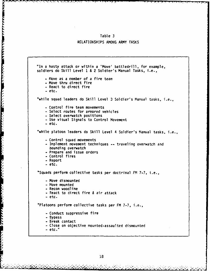
Table 3
RELATIONSHIPS AMONG ARMY TASKS
"In a hasty attack or within a 'Move' battledrill, for example,soldiers do Skill Level 1 & 2 Soldier's Manual Tasks, i.e.,
- Move as a r.ember of a fire team- Move thru direct fire- React to direct fire- etc.
"while squad leaders do Skill Level 3 Soldier's Manual tasks, i.e.,
- Control fire team movements- Select routes for armored vehicles- Select overwatch positions- Use visual Signals to Control Movement- etc.
"while platoon leaders do Skill Level 4 Soldier's Manual tasks, i.e.,
- Control squad movements- Implement movement techniques -- traveling overwatch and
bounding overwatch- Prepare and issue orders- Control fires- Report- etc.
"Squads perform collective tasks per doctrinal FM 7-7, i.e.,- Move dismounted- Move mounted
- Recon woodline- React to direct fire & air attack- etc.
"Platoons perform collective tasks per FM 7-7, i.e.,
- Conduct suppressive fire- Bypass- Break contact- Close on objective mounted-assaulted dismounted- etc."
18
S. . ........ . . . . . . . . . . .. . . . .

Table 3 (cont.)
"Commanders and staffs at company, battalion, and above (1) analyzethreats and terrain, (2) organize for combat, (3) select formations,(4) select routes of advance and employ combined arms, (5) provideadministration and logistical support, (6) and command and controlall elements.
"Tasks in this vertical hierarchy (individual thru battalion command)also fit naturally into a horizontal relationship (e.g., move, shoot,communicate, etc.). When addressed in combination with the verticalcomponents, this natural aggregation of soldier, leader, command andstaff, and collective tasks into these horizontal functional areas issignificant because it provides clear and concise means to train tocriteria. Importantly, as you go from one ARTEP Mission to another,commanders and staffs do remarkably different tasks, but platoons,squads, and their leaders and soldiers do virtually the same thing."
19
2 %2
COMBINED ARMS TACTICS & DOCTRINE (CATD)j
SMALL UNIT TRAINING OFFENSE/DEFENSE
COTO Q GDhEII
*ANALYSIS SOD__L CO BN BDEaINDIVIDUAL M" M U Su SE AT
STUDIES -C>OFF ICE LEADER SELECT SELECT PLAII P LAN SEINNER
COLLECT. REACT CIWW OrThi. ArL PLON
*MNASCOMMAND I DIPLY SPPRT PLANa COM. & STAFF 11LV SPPR7
TEST* BRANCH
DATA BASE DEVELOPMENT
* FIGURE 5. US Army Infantry School Database Development Organization
20
-7 -W 7- 7 7- - - -7 V -V
COMBINE APWS TACTICS & DOCTRINE (CATDI
"VlALL UNIT TRAINING OFFENSE/DFENSE
COYD am
ANALYSIS SOD PLY CO BN
ST) INDIVIDUoAL W Vol PLm sel, 7INCF F ICE LEAOER uucl ucl Ka "m rm UPON
COLLECT. metv cow am aom Km- I
TS COM. & STAFF VilLTEST
DATA BASE DEVELOPt-ENT
ARTEP OEVEL(WP'ENT/AUTHORING
IND_____ S__ PLY SOD PL O O-c m II W..LECTIVE TAK -e
ANM~ A i Tan SOD PL CzIDVONLEAIER uuts Ka no riM - 'ISiCOLLECT. tog. Sa l IX ank
y vmti pu n c cN 01.& STAFF Ir.'m
INTEGRATION OF TASVRtICAL I. I ZONTAL
FIGURE 6. ARTEP Development/Authoring
21

decisions and actions. When individuals' actions have an effect on oneanother, it is often necessary that their actions be coordinated. Thiscoordination is best achieved by a combination of predetermined, commonprocedures (a plan). In this case, the plan consists of TRADOC Regulation310-2 (TEST) and 350-7 (Draft) mentloned earlier.
Coordination also demands efficient communications to expand and refine theplan or product. The amounts, type, and format of information that arerelevant or necessary to allow individuals to successfully carry out theirindividual parts of the plan vary greatly according to the nature of thedependence of their plans on the actions of others. The ARTEP, by its verynature, introduces a hierarchy of information requirements on the part ofauthors. Since the strongest notion of knowledge that a group can have iscommon knowledge, any ARTEP/MTP production system, automated or manual, mustshare knowledge as it is acquired or required. However, common knowledge isreally not practically attainable in manual systems.
The ARTEP development and authoring at the Infantry School, illustrated inFigure 6, shows why this common knowledge is not practically attainable in amanual system. The relationships between MTP authoring, shown in Figure 6, issuch that the variables are difficult to control. Different people, atdifferent places, and at different times are injecting changes at variouspoints in the work flow which are not available to other participants in timeto influence their actions. As a result, a comparison of tasks addressed inthe "How-to-Train" manuals against tasks required in the "How-to-Fight"manuals reveals a pattern of omissions and duplications. Given the complexinteractions depicted in Figures 5 and 6, and the MTP development problems andrequirements discussed above, this is not surprising.
Figure 7 illustrates the entire Mission Training Plan (MTP) production processfrom database development to ARTEP development and authoring through to theproduction of a Mission Training Plan for each unit echelon. NOTE: Thetriangles at the bottom of Figure 7 is a schematic representation of an MTP toillustrate how doctrinal and training developments result in unit trainingplans.
Analysis of the "New" ARTEP/MTP. Discussions with subject matter experts andARTEP/MTP authors at the US Army TRADOC agencies revealed that changesenvisioned in TRADOC Reg 310-2 (Test) will soon result in substantial andsignificant changes in the ARTEP content and format now used in ARTEP 71-2,(the ARTEP chosen by the Infantry School as the focus for the CAPS program).Figure 8 below depicts the form and content of the "new" ARTEP. The reader isreminded that the term ARTEP (Army Training and Evaluation Program) will sooncome to mean the entire body of training literature and the current ARTEP,, asrestructured in Figure 8, will be known as the Mission Training Plan (MTP).The data structures and work flow depicted previously in Figures 5 through 7reflect production of documents in these new formats.
22
@-'S- . .*" *. .*.'.. . . . .."."."'" . • . . . . . . . . ....... . . ..... . .... ... . . . . . . ..

W ~ -,
MALYSIS~ I noiCI m wemA I LDIVKw.E? psT'
1 aU LjhLW11
omR
JUT~~~t VIMIG V4Lro
=Jr ImM I Ia
FIGURENIUA 7.III PUNE Daabs Worfl w wteaSAmyIfgyscho
LEAD son Ke tm 23
-.... . *- 4 . =.. am* af .tf .
Army Training & Evaluation Program (ARTEP)
Mission Training Plan - Squad
1. Inrodution2- Trainn ?aticesF to MT
OnlJ.. to ptission
~ oDllato STX3. Ta~unq ~Lgade! Task to STh3. Trinin Plas~ns Indiv. Task to STX
STXS XUP~rtad Indiv. Task to DrilLoaos Training
Situation4.ST
StndsdLoaom Training
- Leader TaksDrills
s. ~ Saparat* Indvidual,Sac. rills.Tsk
11I TasksSkippat5 Support RquirntsCaonitiom Cornicten the EecseSqt~jp Directions seaiwaili-thruj InstrutionsI Sj"csOf TasksWiustratisIndiv. TasksEI
fllustmtions
TashiMassxau DiagraIStandrdintutions Tss&Ns
S. ~faor developing Cniin
Ref vencsswerenowsSiatasks
Cannon Mdul&& PsourcesMiscellaneousDouetI Iato Abbrviations
Logistics/Meelth Devices ARTEP Task Lists4WTV /i a RuwqssAree Rea. Exercise Control
Freq ReommedatonsReferences
FIGURE 8. "NEW" ARTEP Contents
24

Development of a Mission Training Plan
MTP Authoring Procedures. TRADOC Regulation 310-2 (TEST) provides specificguidance as to tne content, purpose, and format required for each section ofthe MTP. Figures 3 and 4, above, describe in general terms the data flow andproducts of the MTP and responsibilities for the creation and maintenance ofthe database at the Infantry School. What is missing are the detailed stepsand decisions that each MTP author must make to turn "How-to-Fight" doctrine,missions, and tasks into effective "Train-to-Fight" programs. It is thisprocess that is essential to capture within the "Expert Consultant" automationsystem known as CAPS. To begin, let us develop the hierarchy of MTPproduction processes within a framework of input-process-output. Thismethodology provides a graphical description of the functions performed by thesystem. Because we will describe the functions of the MTP production syste-mand not its organization and logic, the reader will be provided with anoverview of what the system does as an aid to understanding subsequentdiscussions of implementation lwho does) unique to the Infantry School. As anaside, Appendix D contains a complete description of the USAIS workstationData Flow in matrix form. This is essentially the same system descriptioncontained in this section, except that it displays each function of the systemwithin the context of the Infantry School's organizational responsibilities.
Figure 9 depicts the hierarchical functions of the ARTEP production process ofwhich the MTP production process is but a part. Note that each function isarranged so as to depict its relation to each other function.
Looking at the Collective Front-End Analysis (CFEA) function 3.0, we can seethat it consists of two subordinate functions listed in blocks 3.1 and 3.2 ofFigure 10. Each function of the CFEA process is further decomposed in Figures11 and 12.
Figure 13 takes us from the CFEA/doctrinal development functions into theproduction of the MTP itself. The reader is urged to familiarize himself withthe system's functions by scanning each step in the process. Figures 14through 21 describe each major function in the process and relate each processto an output. The matrices in Appendix 0 depict these products in terms ofwhich agency at the Infantry School produces the product and who uses it. Thereader should be aware that a continuation of the input-process-output systemsanalysis can be made for each "process" identified above.
To continue, let us now examine some of the generic-type decisions that mustbe made. These are listed below as task criticality dimensions:
1. Learning difficulty. Is the task difficult to learn? KnowingITow difticult in terms of time, resources, and performance isnecessary to determine whether the task should be taughtindividually, collectively or in combination.
2. Performance difficulty. How difficult is the task to performconsistently to criteria? Does time since last successfulperformance influence difficulty?
25

IINTERACTIVELY PRODUCE ARMY
TRAINING AND EVALUATION
PROGRAM (ARTEP) 1.0
DEVELOP COMBINED ARMS
DOCTRINE AND UNIT MISSIONS
2.0
CONDUCT COLL SPECIFY HOW PRODUCE A FORMAT HOW TOFRONT-END EACH ECHELON GLOSSARY OF TRAIN MISSIONANALYSIS 15 TO FIGHT TERMS TRAINING PLAN
(HTF FM'S)3.0 5.0 6.0 7.0
DIEV IND/COLL J
* ~ TASKS ,COUD I-ITAOSSTAN- IDENTIFY TRAIN-T IONS & ST AND- REO CSARDS FOR EACH RESOURCESFUNCTIONAL REQUIRED TOAREA & t'uSsiOuj TRAIN TO FIGHT
4.0
IDENTIFY TASKELEMENTS, CUES& SK ILLS &KNOYLEDGES INTERACTIVELY PRODUCE ARMY
3-2 MISSION TRAINING PLAN (fTP)
FOR EACH ECHELON 4.
8.0
COORDINATION & DISTRIBUTION
FIGURE 9. Hierarchy Plus Input-Process-Output System Analysis for CAPS
26

.7
FROM
CONDUJCT OF COLLECTIVE 2OC.0 N
FRONT-END ANALYSIS
3.0
&T COL.DIV INTSKCTI,
ION&PRODUCTIONAO ARMY3.
IDMISSION TRAINING-
AND KNOWEDPELFN
327
TO .0NTRCTV
.%~~~~~PRDCTO Of%% ARMY~%.~ a~ .~
MISO TRANIN

DVELOP I11ID0VWIDUAL TASKS, CONDITIONS AND
3.1
INPUT PROCESS OUTPUT
A Collective task FEA Famiize aallst v/ iCetre Task
lists for cookd mit organizati n, Lissfor Phase
mtssien phase missions & doctrine ndividual tasks
* -IndInddvidutaskssks,-Inividual taslso.) -Leader tasks
-concttve tasks 0Cosrut battlefield Lead Tasks, -leader tasks organizaton diagram -Command & Satff
-conmmam tasks tasks-ommand & staff 0 Determine Missits
tasks omtrol, mve r Training Infofire. eto) 0 Dtfin Operations -Related tasks
• Standards for each t - Initial trainingollective & Ind 0 Construct Operatios/ timetaskratioli Missn Digrams -Next level coil-Sustainimq task supported
SConditos for- Determn the steps ea Rationale forEcc imost perform toch
0 Mssio Pase perform a gives ln task
-+~love task-Exeeute 0 Determine Task Elements
- -Reerganize For each identified Task
SIntensityp 0 Determine Propeeacy-light For Each Task-medium
-beavgl Compile Caln Task list-echelon-type of task (ops/log TO 3.2 PRODUCE
equip specific) TASK ELEMENTS
FIGURE 11. Develop Individual Tasks, Conditions and Standards
28
'--'::'/-. ," . ,;,.o..:/.-i<?.." " o".:'. :,-..."...•.............-.-.........................-...--........-.-.....*.-..*....-....-....

IENTIFY TASK ELEMENTS, CUES & SKILLS &KNOWLEDGES FOR EACH COLLECTIVE ANM INDIVI--DUAl. T ASK HWDENTIF IED MN 3.-1 FROM 3.1
TASKDEVELOP-
3.2 ME19T
1111lT PROCESS OUTPUT
o Task Idntifieaties Data 0 List task Elmef 0 Task Element(Echelons,* missions ,eto) 0 Ensure all steps in list
a *Information Sources *efriqec lmn Skills & Knowledge(FM-s/TMs/ST-s) isietfd&rcr-reqired
o coos, conditions & aCe*standards 0 Identifig individual tasks
Within the context of 0 CMrifloations &o Prerequisite tasks either the Collective Considerationstask or the specifico Associated Tasksmiso uoeta t
0 Identiffy the echmeowhich performs thetask element.
* List reek task elementaim"' With the cotswhich cause the elementto he performed
TO 9.0 HiP PRODUCTIO1
FIGURE 12. Develop Individual Tasks, Conditions and Standards
29

START
tiesal ~ ~ ~ 2 TraORn PEACHe DEll CHELON Eeie
Develop T&r ED& etToPEc
Mise o Fntin orovr
Echelonlmd.l~a
Ta I n grt m
FIGURE 1.3 Ienif Task Eloets CusTaSilsk
for groups of 3-etltW t~

DEVELOP T & EO & TEST FOR EACH MISSIONOR FUNCTION FOR EVERY ECHELON. FO .
CFE A8.1
INPU PRO~SSOUTPUT
* S~ Task Idctifieatioe Data 0 SELECT MISSIONS FOR ATRING&VA*(Echeones, missioas~ote) UNIT TRAINING OUTLANIG O EAH
MISSION SELECTED0 lnarmatle Sources 0 IDENTIWY TASKS, FOR UNIT TRAINING
-(FMs/TMs/ST's) CONDITIlonS &STANDARDS FOR EACH
a Cues, 006diti..s & SELECTED MISSION- standards
* ARRANGE STANDARDS IN*0 Prerequisite tasks SEQUENCE OF PERFORM-
ANCE0 Associated Tasks
0 IDENT WY AND INCLUDEAPPROPRIATE REF-ERENCES
0 INCLUDE INDIVIDUALTASK NUMBERS DEEMIEDESSENTIAL TO CONDUCTOF ARTIEP MISSION ORMAJOR VAR ENT ORUNIfT TASK
TO 8-2 PREPARATION OFTHE STX AND TO 8.4DEVELOPMENT OF ATRAININO PLAN FOR EACHECHELON
FIGURE 14. Develop T & EO
31

PREPARE A SITUATIONAL TRAINING EXERCISEFOR EITHER EACH T & EO OR FOR GROUPS OFT & EO. GROUP In OF MISIONS & UNIT TASKSINTO -GOOD SLICES OF THE BATTLE' WILL FROMDETERMINE GROUPING OF T &Eo INTO STX 8 B.I
OUTPUTINPUT PROCESS _
0 T&Eo FOR EACH * REVIEW &EO FOR e STXFOR COMPANY
ECHELON COMONALITY Of AND PLATOONCOOLECTIVE TASKS AND
0 CFEA COLLECTIVE & CRITICALITY OF TASKS e MISSION TO COLLECT-INDIVIDUAL TASK TO MISSION SUCCESS IVE TASK DIAGRAMS
DOCUMNET AT IONSUMMARIES * SELECT T &EO FOR o INDIVDUAL TASKS
STX DEVELOPMENT REQUIRED TO BE
e RELEVANT NOV TO TRAINED TO ENSURE
FIGHT (DOCTRINE) S INTEGRATE LEADER TASK COLLECTIVE TASK
MANUALS WITH LEADER TRAINING PROFICIERCY
TO BE CONDUCTED =&4
a SOLDIER'S & MQS WITH STXMANUALS
* IDENTIFY -SLICES ' OFBATTLE BY GROUPING
T &EO
* DEVELOP LEADER TASKS,UNIT COLLECTIVE TASKSAND INDIVIDUAL TASKSINTO A14 STX BY SELECT-ING THE PREFERREDDOCTRINAL METHODOF EXECUTING THE T &Ec
* DEVELOP A TACTICAL TO 8.3 DEVELOPMENTSCENARIOOF SQD/PLATON DRILLTHE FACTORS OF METT-OTO ILLUSTRATE THEPREFERRED DOCTRINALMETHOD OF EXECUTION.
. IDENTIFY T & EO WHICHBE GOOD SQUAD/PLATDRILLS
FIGURE 15. Prepare a Situational Training Exercise
32
• .. -. . . , . ' * " " " " " '. " " " * " " " " .* o* ." -" ." ." ." . . ' R . " " ." " ' .". , . " " ." ' ." " '

PREPARE CREV/SOUAD/SECTION AND/OR PLATOONDRILLS AS APPROPRIATE
8.3 FROM 9-2 STXDEVELOPMENT
INPUT PROCESS OUTPUT
IDENTIFY T & EO S DETERMINE INDIVIDUAL CREV/SQUAD AND/OlFROM STX TO SELECT LEADER AND SOLDIER PLATOON DRILLSCOLLECTIVE TASKS TASKS TO BE TRAINED FOR EACH SELECTEDFOR DRILL DEVELOP- COLLECTIVE TASKMENT S IDENTIFY COLLECTIVE
TASKS TO BE TRAINEDN NOV TO FIGHT BY ANALYZING STX(DOCTRINAL)MANUALS S DETERMINE PREFERRED
DOCTRINAL EXECUTION* CFEA TASK LISTS OF COLLECTIVE TASKS
AND TASK DOCUMENT- WITHIN CONTEXT OFATION SUMMARIES STANDARDS FROM
CFEA OR STX OR BOTH• COMMON COLLECTIVE &
INDIVIDUAL TASKS S AUTHOR DRILLFROM OTHER TRADOCSCHOOLS
TO 8.4 DEVELOPMENTOF TRAINING PLANS
FIGURE 16. Prepare Crew/Squad/Section and/or Platoon nrills
33

8.4 DEVELOPMENT
ru'UT PROCESS OTU
o 4WT RI MREVIEW THE CVEA AND SAMPLE UNIT* MW T TAINFMSmX/DRILLS TO ISOLATE TRAING PLAN
* HOW TO FIGHT FM GROUPS OF TASKS OR FREC CEOMISSIONS MOST LIKELY FREC CEO
a M4T STX & DRILLS TO RESULT IN COMBAT eSPOTN ISOEFFICIENCY WHEN TAS SU DIAGAMSSN
* 6~ RESOURCE GUIDANCE TRAINED TO STANDARDSTAKDGRM
* FE TSKDOUMNT- REVIEW HOW TO TRAINT FA TASKDON AND HOW TO FIGHT
TATIONLITERATURE TO DEVELOP
* COMON ND SAREDKNOWLEDGE IN TRAININGD OM OCUNTATION MANAGEMENT NEEDED TO
TASK DCMNAINDEVELOP A TRAININGPLAN
*SELECT STANDARDS ORUNIT ACTIONS BESTTRAINED IN COLLECTIVECONTEXT
*DEVELOP ILLUSTR AT IVETRAINING PLANS TOCOVER A I TO 6 MONTHPERO TO DEMON-STRATE TO UNIT HOWA TRAINING PLAN ISUSED TO INTEGRATETRAINING Of MISSIONS. TO 8.5 COLL/INDIYCOLLECTIVE AND INDiY TASK INTEGRATIONTASKS WITHIN A MULTI- &ECHELON PROGRAM- 8.6 DEVELOPMENT
OF UNIT FTX
*ISOLATE TRAININGRESOURCES REQUIREDTO EXECUTE THE PLAN
FIGURE 17. Develop a Training Plan
34

FROM 8.4 MTP
8.5 TRAININ PLANS
INPUT POESS OUTPUT
*SCOLLECTIVE FRONT- 5ANI.YSIS OF UNPUT a INDIVIDUAL TOEND ANALYSIS (CFEA) PRODUCTS TO QUANT IFY COLLECTIVE TASKTASK LISTS AND THE REAIOSI OF INTEGR AT IONDocUIMENr SUM-. COLLECTIVE T ASKSMARIES FROM 3.0 (PERATOSAL, SUS- * TASK MATRIX PUB-
TAWIN6 & EQUIPMENT LISHED FOR IN-*STSX & DRILL TASK SPECIFIC) CLUSION IN THE
LIST FROM 8. 2 & MT? UNDER DEVELOP-8.3 aARRANGEMlENT OF IND IV- MENT AND DISTRIB-
IDUAL TASKS WITHIN UTION TO OTHER*6VERTICLE INTEGRA- COTf OF THE COLL- AFFECTED SCHOOLS
TRWN OF COLLECTIVE ECTIVYE TASK WHICH& INDIVIDUAL TASKS THEY SUPPORTFROM 8.3 ____ ____aISOLATION OF LEADER,
COMMAND AND COM-MAND AND STAFF TASKS
TO 8.6 DEVELOPMENT OFTHE FTXTO 8.7 DEVELOPMENT OFTRAINING MATRICES
FIGURE 18. Identify and Produce Task Integration Matrix
r 35
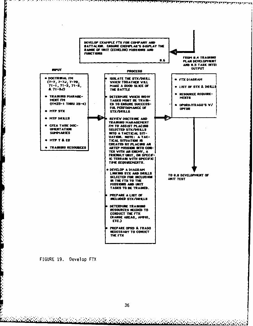
DEVELOP EXAM"PLE FIX FOR COMPANY AMBATTALIN. ENSURE EXEMPLAR'S DISPLAY THERAGeM OF NIT (ECHELON) POS n I ANDFUNCTIONS
FROM 8.4 TRAINNG8.___ PLAN DEVELOPMENT
AND 8.5 TASK IITEEOUTPUTINPUT" PROCESS OTU
e DOCTRINAL Ff4 ISOLATE THE STX/DRI.L 0 FTX DIAGRAM(7-7. 7-7J, T-70, WHENI TOATHER VILLI71-1, 71-2, 71-3, MAKE A GOOD SLICE OF S LIST OF STX & DRILLSA 71-3J) THE BATTLE
SRESOURCE REQUIRE-* TRAINING MANABE- DETERMIE VHICH INDIV MENTS
MENT F4 TASKS MUST BE TRAIN-(F123- THRU 23-4) ED TO ENSURE SUCCESS- * OPORD/FRAGO'S V/
FUL PERORANCE OF OPFOR* NTP STX STX/DRILLS
* MTP DRILLS REVIEW DOCTRINE ANDTRAINING MANAGEMENT
* CFIA TASK DOC- FM TO ASSIST PLACINGUMENT AT IEC SELECTED STx/DRILLSSURIARIES INTO A TACTICAL SIT-
UATIN. NOTE: A TAC-0 KTW T & ES TICAL SITUATION IS
CREATED BY PLACING AN* TRAINEES RESOURCES ARTEP MISSION INTO CON-
TEX WITH AN IDIEY, AFRIENDLY WNIT. ON SPECF-C TERRAIN WITH SPECITIME REQUIREMENTS.
0 DEVELOP A DIAGRAMLINKING STX AND DRILLS TO 08 DEVEPMENT OFSELECTED FOR INCLUSION UNIT TESTm THE FIX TO TIEMISSIONS AND traITTASKS TO BE TRAINED.
PREPARE A LIST OFNICLUDED STX/DRILLS
DETERMINE TRAININGRESOURCES NEEDED TOCONDUCT TIE FTX(RANGE AREAS, AMMO,
ETC.)
PREPARE OPRD & FRAGONEDESSARY TO CONUCTTHE FTX
FIGURE 19. Develop FTX
36

DEVELOP THE TRAINING MATRIX
FROM 8.5 COLL/INDIY8.7 TASK INTEGRATION
INPUT ROSSOUTPUT
*TRAINIG PRODUCTS SISOLATE MTP SPECIFIC SFTX TO STX MATRIXFROM 9. 1 T & ED;8.2 STX; 8-3 DRILLS; STDILFX DRILL TO STXAND 9.6 FTX S DEVELOP REL AT ION- MATRIX
SHIP BETWEEN:*COLLECTIVE/ NDIV- - FTx & six LEADER TASK TO
DUAL TASK INTEGRA- - DILL & STX STX MATRIXTION MATRIX - LE ADER TASKS & DIVDULTAS
six~T ST I MIVDATASK- MNIVIDUAL TASKSTOTXMRI
& SiX- INDIVIDUAL TASKS SINDIWVIDU AL T ASK
Si DILLSTO DRILL MATRIX
CONDUCT A TASKINVENTORY TO ENSUREALL TASKS ARE AC-COUN9TED FOR & ALLT ASK REL AT IONSHIBPSTO TRAINING PROD-UCTS ARE IDENTIFIED.
*ARR ANGE T ASKS ANDTRAMNING PRODUCTSINTO MATRICES.
TO 8.9 DEVELOPMENT OFUNIT TEST
FIGURE 20. Develop the Training Matrix
37

DEVELOP THE UNIT TEST
FROM 8.6 FTX8.8- DEVELOPMENT &
ALL OTHER TRAIN-PRODUCTS
INPUT PROCESS OUTPUTi
0TRAIN ING PRODUCTS iEE TINPUT 0UNIT TESTS FOR:FROM 8.1I T & ED; REFERENCE MATERIAL -SQUADS8.2 STX; 8.3 DRILLS; TO ISOLATE UNIT TEST -SECTIONSAND 8.6 FTh. PURPOSE, FORMATS, -PLATOOKS
POCEDURES- -COMPANIES*0COLLECTIVE/INDIY-EETSQASC
DUAL TASK INTEGRA- PSLETO S&A SECANTION MATRIX PLTO & COMAN
* 0TRAINING MANAGE- *DEVELOP AN OPFORMENT FM YHIC IS REALISTIC
FOR THE ECHELON TEST*6TRADOC REG 310-2 scmI DEVELOPED
(TEST)*REYIEW TRAINING
MANAGEMENT &TRADOC REG 310-2(TEST)
*PREPARE ILLUSTRATIVETEST FOR EACH UNIT
TO COMPLETED MTP FORCOORDINATION & RE-VISION
FIGURE 21. Develop the Unit Test
38

77I
3. Time delay tolerance. What is the time delay allowed betweenreceiving the task cue and starting the task performance?
4. Consequence of inadequate performance. What other tasks areaffected?
5. Immediacy of performance. How soon after achieving taskproficiency can the crew/platoon/individual be expected toperform the task again?
6. Task importance. How important is an individual task tocollective/unit success. Another way to ask this question is todetermine how often a collective task is a component of an ARTEPmission.
7. Combat criticality. Can the task only be performed in combat, orcan it also be performed in administrative or trainingsituations? An example can be found in the tasks ofdecontamination of nerve agents and TOW missile firing. In bothcases the tasks are combat critical. Decontamination of actualnerve gas agents can be accomplished in combat only since the USArmy is not allowed to train with live nerve agents. TOWmissiles however, are combat critical but can be trained to alimited degree only (due to the cost and consequent limitedavailability of TOW missiles) in time of peace.
8. Proficiency decay rate. How often must a task be performed toensure that skills are not reduced below performance measurestandards considering time, personnel turbulence and taskdifficulty?
Obviously the answers to these questions are dependent on unit conditions andthe amount and quality of data available to the MTP author. However, answersare necessary to develop an effective MTP. CAPS developers should examine thedatabase elements to determine the best design for a system to assist theauthor in answering them.
Once the MTP author makes decisions as to task criticality, he facesARTEP-unique problems of data aggregation that must be solved if he is toproduce an effective Mission Training Plan (MTP). Remember, the MTP as nowdesigned describes unit training requirements in a way that reflects theresults of a training oriented analysis of collective tasks.
The MTP author must identify slices of the battle that could be practiced as
specific drills or Situational Training Exercises (STXs) (see Appendix E,
Glossary). The author must also develop "Training Roadmaps," which linkskills and tasks to missions in a logical manner so that attempts to train adifficult task are not made until all included, less difficult tasks have beenmastered. In a training situation that mandates multi-echelon, integratedtraining, this "roadmapping" requirement is an obvious candidate for automatedsupport.
39
....................................-i | -.. I -- i d -J ..

Last but not least, the MTP author must deal with the integration ofindividual and collective tasks as well as the integration of collective tasksto ARTEP missions and all the other matrices required by TRADOC Reg 310-2(Test). (i.e., FTX-to-STX, Drill-to-Mission, Leader Task-to-STX, IndividualTask-to-STX). Here again, automated support could vastly simplify his job.
In sum, the MTP author must conduct a training collective task analysis, usingthe products of a doctrinal collective task analysis. This process isillustrated by the diagrams in Figure 4 above, that show the CFEA data flowfrom the database to the Training & Evaluation Outline (T&EO) thru the MTPauthors of DOTD and CATD. With the development of the T&EO, the MTP authorsstart the process of describing unit training requirements, a process thatends with the completed Mission Training Plan (MTP). Field Training Exercises(FTXs) are developed as part of the Mission Training Plan, to illustrate tocommanders and unit trainers where the drills and STXs come together as a unittactical capability within the context of unit missions.
Figure 22 depicts twelve sequentially interrelated processes, each of whichinvolves a number of internal steps that are necessary to produce an MTP.CAPS will be designed to support these processes, beginning with thedevelopment of detailed T&EO and tests ending with the ARTEP Mission TrainingPlan Development. Coordination will occur "off-line." While revisions willinput to the CAPS system, this input will occur at the CFEA module as anyother CFEA input. Printing and preparation by the Department of the Army isoutside the CAPS design at this time.
Preparing Training and Evaluation Outlines (T&EO). A detailed T&EO consistsof (1) one or more missions or function(s) of a specific unit (e.g.,battalion, squad; by type), (2) conditions, (3) subtasks, (4) standardsarranged in the proper sequence of performance, (5) references, and (6) tasknumbers of separate individual tasks deemed essential to the successfulconduct of the ARTEP mission or a subtask.
The T&EO is developed by the ARTEP author, based on the data provided by theCFEA. The CFEA identifies all unit missions for each echelon from squad tobattalion. The School commandant convenes a selection board to determinemissions that are essential for all like units to perform. Selected missionsare incorporated into the MTP by the preparation of a T&EO and become the corefor which all collective tasks, drills, leader tasks and STX are to bedeveloped. T&EOs, which support other missions that are deemed less essentialor are unique to specific units, will also be included after all essentialmissions have been developed.
Detailed information regarding preparation of a T&EO is cortained in Chapter 3of TRADOC Regulation 310-2. A sample T&EO is shown in Table 4.
Preparing the Situational Training Exercise (STX). STX are mission-orientedexercises, designed to be ot short duration, and are simple field exercises totrain a group of closely related collective tasks. They are illustrative innature as they depict a doctrinally preferred method of executing thecollective tasks to established standards. The STX is developed after thecompletion of the T&EOs, which have been prepared for each essential mission.
40

* I SELECTIONPPIORTY OF ARTEP CP UPRE
DEVELOPMIENT CP UPRE
[ COLLECTIVE DETAIL.ED T&EO
COLETVE TASKICESELOEte4
INRIVIDUA TIARI
DEVELLOPMENT
DEVELOPMENTT
FIGUE 22 Prcesss intheDeveopmNINGth PLN
41EVLPMN*,. *.<?~ .. .. *.*.
L:

TABLE 4
SAMPLE TRAINING & EVALUATION OUTLINE(From Training Circular 17-15-1,
Tank Platoon Mission Training Plan, dated Jun '84)
TASK NUMBER: 076 (Task Number is assigned during CFEA)
TASK STATEMENT: Execute a Hasty Attack
CONDITIONS: Day or night, under any climatic conditions as part ofoffensive operations. The OPFOR may be static ormoving.
STANDARDS:yes no NE
Subtasks: (not eval)
The Platoon:
I. Reacts to OPFOR presence without hesitation
2. Initiates fire and morement to destroy OPFORbefore being fixed by the OPFOR.
3. Conducts the assault.
a. Insuring that maneuver elements are overwatched.
b. Using suppressive fire against the OPFOR.
c. So that maximum available combat power is concentratedagainst the OPFOR at the decisive time and place asdetermined by commander.
References: FM 17-15 (test); Division 86 Tank Pit., Chpt 3, Para 3.2 & 3.3FM 17-1gE 1,2, & 3; Soldier's Manual for MOS 19E
Individual Task Numbers:Platoon Leader: 171-140-4016
171-326-3049Soldier's Manual
Skill Level 3: 071-331-0820 Skill Level 1&2: 071-326-0608171-127-1001 113-571-1005etc. etc.
NOTE: This example differs from TRADOC Regulation 310-2 in that theevaluation columns grade on Yes/No or not evaluated. The regulationcalls for a five column evaluation format ranging from 1-5.
42
• -' ' .... " : "'/' l" " ' ,'- , ' ,' , ' , . ""w . . ,' .' " - K - "K.V..' .%. '.'-.
Components of the STX are designed to integrate leader training, leader tasks,drills, and individual soldier tasks into a realistic combat scenario.Trainers may execute them as written or tailor them to meet specific trainingobjectives. In either case, the performance measures are to be executed toprescribed standards.
Application of the STX, due to the design criteria above, are applicableprimarily at the platoon and company level. If, however, the MTP author
* determines that higher level command and staff tasks require STX to train," specific tasks or drills most efficiently, the appropriate STX should be
developed and integrated into the MTP.
STX combine the "How-to-Train" specifics for selected collective tasks withthe "What to Train" found in doctrinal manuals. STX have define start andstop points and are used repetitively to train to unit criteria.
The following questions must be answered by the MTP author when he designs the
1. How critical are the missions and unit functions to the combatcapability of the unit. Such factors as stated missions,critical combat collective tasks and implied missions, allavailable in the CFEA, help the author narrow the focus of STXdevelopment.
2. What slices of the battle make good training exercises? Theauthor must make a training analysis of the missions and tasksidentified in the CFEA to aggregate the data into reasonablechunks of time, personnel and tasks. An example would be theARTEP mission for a platoon of the Hasty Attack.
" Let us decompose this mission and see the elements of decision making anddesign that goes into the authoring of an STX. We will follow this with thepresentation of a sample Hasty Attack STX. To begin, the ARTEP author reviewsthe task mission and task list from the CFEA. Under "Missions" he finds theplatoon and squad execute the hasty attack as part of the movement to contact.He finds further that execution requires platoon proficiency in unitfunctional areas of "Fire and Movement," "Movement" "Shoot, "Sustain" and"NBC." This tells him that an STX designed to train a platoon in the hastyattack must contain drills, individual tasks, and leader tasks from all ofthese functional areas. Because the database contains the vertical andhorizontal integration of tasks, missions, and echelons (individual to platoonin this case), the ARTEP author can now list and diagram all collective tasksin the hasty attack ARTEP mission. We see this below in Figure 23.
Once the MTTP author has diagrammed the proposed STX, he goes back to the CFEAto determine which individual and leader tasks are required to allow the
platoon to execute each of the collective sub-unit tasks. He will list the-L tasks for use in the published STX/MTP. He will also, at this time be looking;: for ARTEP tasks within the STX diagram (as shown in Figure 23) that will be
good candidates for development as drills. We will discuss development of
43

MAJOR MISSION VARIENT NSYATC
UNIT TASK (TRAINED BY THlE STE)
rNOVINIUT TO CONTACT
PEiFOR'1 PERFORM MOVEMENT EXECUTE BOUNDING MOVE USING MOVE USINGSUBUNIT SECURITY SECURITY USING OVERVATCK VEDGE FORM- LINE FORM-(Drills) ACTIVITIES SMOKE Tusk 301 Platoon Drill ATION ATION
(Drlb PatonDrllPlatoon Drill Platoon Drill
SUBUNIT DEFEND AGAINST EXECUTE ACTIONSTASKS All ATTACK ON CONTACT<Drills) Ts 4
LEFT (RIGHT) LEFT (RIONT)
FRONT (REAR) REAR
LEA DER TASKS PERFORIM PLATOON ESTIMATE Platoon Drill
FIRE DISTRIBUTION THE SITUATI ONAND CO0NTROLTask 137
SUBUNIT TASKS MAINTAIN EXECUTE A BY PASS AN
RESULTING CONTACT WITH PLATOON ENL71 POSI-FROM LEADER AN ENEMY lASTY ATTACK TION
TASKS Task 16972
SUBELEIENT ENGAGE TARGETS ASSAULT AN MOVE ON SELECTEDCOLLECTIVE L Task 107 ENEMY P051- ROUTE USINGTASKS| TION OVERVATCR
TO INDIVIDUAL TASXS Task 173 TECHNIQUES
FIGURE 23. Example STX: Platoon Hasty Attack
44
. z-. *-

drills in detail in the next paragraph. At this time it is sufficient for thereader to know that it is here that the best look is made to identifypotential drills. The next step in STX development is to turn to FM 25-3, Howto Train, and develop the "Tips to Trainers" portion of the STX. Using thT-Field manual, and his experience, the author discusses the leader's steps inpreparing for the conduct of the STX. The remainder of the STX consists ofthe preparation of the Fragmentary Order (FRAGO) that establishes the"Situation" in the Situational Training Exercise. A FRAGO looks like this:
"(Your Platoon), IN CONTACT WITH SQUAD-SIZED ENEMY FORCE. (YourPlatoon), STZE OBJECTIVE . COORDINATES (
PLATOON (Simulated) and (Sister platoon) F FIREtOTNATU ( ). ACKNOWLEDGE.
The FRAGO above provides all that the Platoon Leader/Sgt needs to know to planan exercise. To Wit: The Mission - "Seize an Objective", the Eremy - "asquad-size force", Troops - "Your platoon supported by two other-TaEoons",Terrain -Ias specified-y "Coordinates", and the Time - implied "As soon aspOsslble." Now, the ARTEP author has only to establ-Tsh the Standards for theSTX and he has a completed product. The Standards come directly ,ut of theCFEA data base, Phase V, product 3. A standard is prepared/published foreach task contained in the STX. After development of the drills, which willbe integrated into this STX, the drill standards will be used for each taskthat is trained by drill performance.
Remember, that the MTP author must also develop "roadmaps," which link skillsand tasks to ARTEP missions. Now lets look at the Platoon "Roadmap" as thisis really the Mission Training Plan "Big Picture." From Figure 24 we can seethe "roadmap" emerging. Look at the top of the triangle. The platoon ARTEPmissions, derived from the CFEA are all listed, including our example "HastyAttack." Put any Mission at the top and the MTP author can go down thru thecollective tasks of command and control and supplemental tasks such as ControlCombat Operations, reporting, and maintaining operational security and getright into the individual leader and individual soldier tasks. From this"Training Analysis," the MTP author can develop his collective-to-individualtask integration matrices, as shown and discussed previously in Figure 7. Heis then ready to develop the squad/platoon drills.
Development of Drills. Drills are used to train small units (infantry squador platoon, tank crew or platoon) to a peak of performance on those collectivetasks that are always performed in the same way. In other words, the purposeof the drill I terally is to condition each member of a unit to perform hisindividual tasks within the context of the collective task, the same way timeafter time. An analogy can be made to the football squad. The actions ofeach team member are practiced for each play over and over so that suchactions as pass-run coordination, or the bump and run, are executed to precisestandards of timing and individual skills. So it is with a tank crew engaginga tank target or a Bradley Fighting Vehicle Squad dismounting for a dismountedassault.
45

conduct attack an occupy Haty Attack Def Urban
a1mbuth urban ausembly area
%~ra PLT at ocupcond4uct raid OCp
tatiaHIISSIO battle
road march~ drills/SuppC3 \ST took# COLLECTIVE TASKS
SKILL LEVEL IV Leader Tasks
SKILL LEVEL III
SKILL LEVEL 2
/ SKILL LEVEL I IND TASKS
FIGURE 24. Platoon Mission Training Plan
46

Drills then describe a small portion of the battlefield and are to an STX as aplay is to a series of plays. They are designed to capitalize on a specificsituation. Drills are comprised of both collective and individual tasks,designed to hone collective skills. To develop a drill, the MTP author looksat his inventory of STX and by analysis determines which collective task heselected as a drill candidate during STX development. Using the same "HastyAttack" STX we examined in the discussion on STX development and Figure 23, wecan see that the following tasks are good candidates for drill development asthe prime training vehicle:
1. All of the platoon movements that occur in fixed formations suchas (1) execute bounding overwatch, (2) move using a wedgeformation, (3) a line formation, and (4) execute action right andleft, are good candidates as they are always done in the samemanner and are initiated on the same cue, either enemy action orvisual signal.
2. Defense against air attack and surveillance activities are alsocandidates for the same reasons. Each requires a uniformcollective response and each has the stability of uniformindividual tasks.
Once again we see the relevance of asking the MTP author to do a traininganalysis, which will identify slices of the battle and integrate individualand collective tasks with ARTEP missions. Do these tasks require collectivepractice? Clearly, the answer is "yes." Can we identify tasks that apply toleaders? Again, the answer is "yes." Leaders designate the routes andformations and determine the direction of the platoon's actions. Unitfunctions related to movement and fire and maneuver are involved and Soldier'sManual tasks can be clearly identified and integrated into the drill (mapreading, driving, visual signals, etc.).
Let us look at the Hasty Attack Diagram after the author has conducted hisanalysis of those tasks that should be supported by drills. An illustrationis shown at Figure 25.
To develop an MTP drill from this point the author proceeds as follows:
1. First, he determines the individual leader and soldier tasks bytask number, title, reference, and standard for each selecteddrill within the STX.
2. Secondly, he selects/identifies each collective task by tasknumber, title, and reference for the squad/crew and for theplatoon.
3. When he has assembled these data, he starts to author the drill.
In this case the STX we are working on is the "Hasty Attack" and we are goingto develop the "Move by Wedge Formation" Platoon Drill. Drill-to-ARTEP Tasklinkage is a list of ARTEP missions, by title and number that will besupported by this drill. They are:
47
4r

M-SSION ATTC
MAJOR MISSI ONVARIENT !ZASTT AT
* UNIT TASK (RAINED BY THE STI)NOVININT TO CONTACT
PERFORM PERFORM OVEMENT EXECUTE TRAVEL MOVE USING MOVE USINGSSUIT SECJRITY SECURITY II1 OVERVATCM VE DOE F ORM-I LINE FORM-TASKS ACTIVITIES SMOKE T2k 301 ATION ATION
Pltoon Drill Platoon Drill Platoon Drill
SUUI DEFEND AGAI)U EXECUTE ACTIO0NSTASKS AlI ATTACKI ON CONTACT
lnetoo Drill Took 147
EXECUTE ACTION EXECUTE MOVE1 ILEFT (RIGHT) LEFT (mRT)
* ~LEA DER TASKS PEFORM PLATOON ESIAEOFON(EA) EAFIRE DIST BRUTION THE SITUATI ON
AND CONTROL took 36
SUBUNIT TASKS MAINTAIN EXECUTE A BY PASS ANRESULTING CONTACT WITH PLATOON ENmy POSI- comnimcuteFROM LEADER AN ENEMY HASTY ATTACK TION -ui visa.l iTASKS Tok 169 Tok 76 Tak 172 DRIVE TRACKED
" ,T ICLES
*SUBEI.EIIENT ENGAGE TARGETS ASSAULT AN NOVE ON SELECTED RPRSOLLECTIVE Task 107 ENEMY P0SI- ROUTE USINGR
*TASKS (CREVS) TINOEVTXpeom LOAD. ETCTO INDIVIDUAL TASKS Teak 173 TECHNIQUES drill-
FIGURE 25. Drill Diagram, with Drills Identified
-48
J.48%,
a. Moveb. Attackc. Defend
Each of these ARTEP Missions is comprised of other collective tasks besides"Move by Wedge Formation." Each of these other collective tasks are to belisted. Together, the ARTEP Mission Major Variants and Collective tasksprovide a complete ARTEP-to-Drill task linkage and allow the author to workwithin the context of the entire MTP. This ensures that the trainer using theMTP is training within the MTP. If this is confusing, go back to Figure 2 andlook once again at the cubes and data flow. What we are after here isaccountability of all missions, variants, tasks, etc., and context (i.e., wetrain to move by wedge formations within the context of move, attack, defendARTEP missions, variants, tasks, etc.. We also go from a wedge into anassault that requires a line formation, or we by-pass resistance which mayrequire an echelon or a column). By always ensuring the integration of thesetasks, the author can coordinate T&EOs, with STX, with drills, andillustrative Field Training Exercises (FTX), and have a coordinated MissionTraining Plan that is ready for use.
Completion of the task integration phase prepares the author to write thedrill. He does this by a combination of (1) writing the tasks, conditions,and standards right out of the CFEA data base, (2) illustrating the plan viewof the location of each vehicle (or soldier for a dismounted "move in WedgeFormation" drill), (3) establishing the initiating cues, and (4) detailing theperformance measures for each member of the platoon. These performancemeasures are derived from the individual tasks available from the CFEA. Awedge formation drill is shown in Table 5.
Developing Training Plans. Training plans are the plans that unit COMANDERSmake to implement the MIPs in their units. These plans coordinate"How-to-Train" doctrine and "Train-to-Fight" programs by development of aconcise training strategy that combines individual and leader training, drillsand other collective tasks into STX. STX support unit conducted fieldTraining Exercises (FTX), which, in turn, lead to unit mission (combat)proficiency. The training plan emphasizes (1) integration of tasks, (2)sustainment of proficiency, (3) decentralization of planning, and (4)multi-echeloned conduct of training. Decentralization means that the trainingplan provides flexibility for each level of training responsibility (e.g.,squad, platoon, company, etc.) to develop plans unique to their requirementswithin the overall framework of the STX, drills, FTX, etc., which comprise theMTP. Multi-echelon refers to the preferred training method (i.e., within thecontext of normal roles and missions of each echelon). Here we expect thecompany command elements to train on command tasks while one or more platoons
*are conducting an STX/Drill. For example, one or more squads within a platoonmay simultaneously conduct individual training, while other squads practicethe collective tasks appropriate for the STX/Drill of the parent platoons.
Actual design of a training plan is a leader responsibility. The MTPprovides the leader with sample plans illustrating design and trainingtechniques, as well as samples of a training strategy. These sample plansprovide the MTP user with two things:
49

TABLE 5
DRILL DESCRIPTION: WEDGE FORMATION
DESCRIPTION: The wedge formation is used for tactical cross-countrymovement. In this formation the tanks in the platoon move as shown inbelow and maintain their positions relative to each other using thewingman concept. The wedge formation permits excellent fire to thefront and good fire to each flank.REFERENCE: TT 71-1/2, Vol 11.
DRILL TO ARTEP TASK LINKAGE: The wedge formation supports thefollowing ARTEP 71-2 missions:
a. Move:(1) Move in Bounding Overwatch (3-IV-1-9).(2) Move in traveling (3-IV-1-7).(3) Move in traveling overwatch (3-IV-1-8).(4) Cross SP/LD (3-IV-1-3).(5) Move (3-11-4-1).
b. Attack:(1) Move (3-IV-2-1).(2) Conduct a hasty attack (3-IV-2-8).(3) Assault (3-IV-2-11).(4) Conduct Passage of Lines Forward (3-IV-2-2).(5) Bypass (3-IV-2-12).
c. Defend:(1) Move (3-IV-2-1).(2) Conduct Passage of Lines Rearward (3-IV-3-10).(3) Conduct Fire and Movement (3-IV-3-8).
SPECIFIC PREREQUISITES: Knowledge of wingman concept.
HOW TO TRAIN DRILLS: See paragraph 3-7.
4
50
., ..- . .
' " ' . * *' ' * -* ..% , '/ ' " ' , . - ." - .- - .. ". -'. '- -- ''.' ''.'. ' ' '

m'~ - ~ ~ -- L ~ ~ ~ ' ~ - - -, -. r -. -
4
TABLE 5 (cont'd)
h
PERFORMANCE OBJECTIVES:
a. Task: Execute wedge formation.
b. Conditions:
(1) A tank platoon in any moving or stationary formation.(2) Terrain suitable for movement into a wedge formation.(3) An initial cue.
c. Standards:
(1) Platoon moves into a wedge formation without delay.(2) Tanks are positioned generally as shown in Figure 3-7.(3) Vehicle intervals are in accordance with platoon leader
direction/unit SOP.(4) Main guns are oriented in the same general direction as
shown in below.(5) Platoon maintains ground and air security.(6) Platoon maintains radio-listening silence when in open
hatch mode.
INITIATING CUES:
a. Hand and arm/flag signal (see Figure ).b. Voice command (FM radio) - Platoon calT sign:
"BRAVO 6 ROMEO -EXECUTE WEDGE."
51

TABLE 5 (cont'd)
PERFORMANCE STEPS:
(After PL gives initiating cue)K 1 (PL TANK 2 TANK 3 (PSG) TANK 4
a. Takes up the Moves to the Moves to the Moves to thedirection of left rear of right rear of right rear oftravel, tank 1. tank 1. tank 3.
*Orients the *Orients the *Orients the *Orients themain gun main gun main gun main guntoward the toward the toward the toward thefront. left front. front. right front.
b. Maintains Maintains Maintains Maintainsorientation lateral lateral lateralon axis of dispersion dispersion dispersionadvance, in accord- in accord- in accord-PL directs ance with PL ance with PL ance with PLlateral direction/ direction/ direction/dispersion. unit SOP. unit SOP. unit SOP.
c. *Maintains *Maintains *Maintains *Maintainsground and ground and ground and ground andair security, air security, air security, air security.
*Maintains *Maintains *Maintains *Maintainsradio- radio- radio- radio-listening listening listening listeningsilence. silence. silence. silence.
This action must be performed throughout the drill.
52
. ~.I

1. A set of plans that a typical unit can follow to reach missionproficiency.
2. A departure point for unit development of training plans based onunique unit missions, personnel conditions, terrain andfacilities.
A training should be designed to cover a period of from one to six months.That is, it should represent the amount of collective training time availableto a unit within one to six months. Sample Training plans are shown atAppedix H. These are drawn from TRADOC Circular 310-2 (TEST) and are providedhere for ease of reference. The MTP author develops these samples by:
1. Reviewing the CFEA and STX/ Drills to isolate groups of tasks ormissions that, when trained to proficiency, are most likely toresult in the most combat capability. It is this criterion thatwill most likely cause a unit commander to assign top trainingpriority. In reality, this is primarily a function of how oftena collective task appears across the range of missions."Movement" is a good example. "Shoot" is another. Together,they constitute the core group of collective tasks essential to"Fire and Movement."
2. Developing a FTX in which the unit expected to actually executeand evaluate its proficiency in the selected groups of tasks.(The characteristics and developing steps of an FTX are discussedin the next paragraph.)
In developing the sample Training Plan, the MTP author should ask and answer
the following questions:
1. Which tasks require collective practice on the part of troops?
2. What are the standards and performance measures that apply tounit leaders in the excution of these collective tasks?
3. Which unit functions (movement, fire and manuver, sustainingoperations, defend a battle positions, defend urban terrain,etc.) are supported by the selected collective task? The planshould contain elements of each unit function.
4. Which of the ARTEP Missions and Variants do each of the ARTEPtasks and collective tasks selected for inclusion in the trainingplan support?
5. Which actions/standards can be meaningfully trained only in thecontext of a collective exercise?
6. Which tasks must be mastered, in whole or in part, before a unitcan train to the next higher or adjacent (vertical/horizontal)task?
53
"-:-'- :' -. i - -'-"."-. . -"- '. -. . . .. '- - . . '. .-- . -. - --.- . .-*.. . . . . . . . - . . . .: . .. " =" r - : f , f l' :f ,i T-,, .- ,' . .' ,' . . ... . .. .. n -

r1
7. What training resources are required to execute the trainingplan? (Resources are developed fc- each exercise in the plan.)
A mission training plan diagram for the Mission of "Attack" is shown in Figure26.
Developing the FTX. Field Training Exercises (FTX) are groups of STX, whichcontain the drills, placed into a tactical scenario by the addition of anOPORD/FRAGO, and tied to specific training objectives and resources. FTX arenot prescriptive, as are drills, but are descriptive in that the unit is freeto execute them as designed or to use them as a "template" to design FTX forunit unique requirements STX and drills and individual tasks are mandatory.
The FTX is part of the Mission Training Plan. Illustrative examples of theFTX are prepared by the MTP author, as discussed previously in the section ondevelopment of training plans. In fact, Figure 10 diagrams the essentialelement of an FTX for the Hasty and Deliberate Attack. Although the NightAttack is included in the diagram for completeness, the major variants thatmake the Night Attack distinct from the deliberate/hasty attack were omittedfrom the example. Notice that the major variants that comprise the HastyAttack (i.e., movement to contact, breach obstacles, and tactical road march)have already been developed as STX. The same is true for the major variantsof the Deliberate Attack (i.e., the passage of lines, and establishment ofnear and far bases of fire). (STX will also have been developed for the NightAttack by the time the MTP author reaches development of FTXs).
Each FTX consists of:
1. An FTX diagram similar to the one in Figure 10.
2. A list of STX that make up the FTX.
3. A list of drills supporting each STX (this list is already a partof the STX).
4. Resource requirements:
a. Maneuver area recommended as required to perform the STX andsupport additional actions the MTP author seems necessary. Anexample of an additional FTX action would be the training ofthe battalion tactical operations center and the battalionsupport platoon within the conduct of a company/team FTX. Inthis case, the example FTX would display additional resourcerequirements.
b. OPFOR recommended as required to provide the needed enemy foreach STX.
c. Communication, command and control (C3) as required.
54
' ..

07 W.- . -7 - T-
MIISSION
DELIBRATE 1HATY NGHT AJOR
ATTACK ATTACK ATTACKI VARIANT
PASSAGE 1OVEN'ENT BRAHESTAB ESTAB TACTICAL UNIT TASKS
OF LINES CON_ F1- AR NEAR ROA D SXTACT TACLES FIRE FIRE MIARCH
TERDILL flOVE IN SUBUNITBOUNDINGTASKSOVERATCH(DRILLS)
ELET ROTI ISSU VARINGLEADER(FRO1 MA WAPINGTASKS
SUPERVISE COIIIIM41CATE SUBELEIIEWTPREPARATION WITH VISUAL LEADERFOR ACTION SIGNALS TASKS
*PERFORM EOT RV TRACKED OTHER IDIVIDUAISURVEILLANCE I IVEHICLE IINIITASKSTASKS TAIIS SS
4, FIGURE 26. Training Plan Mission-Task Diogram
.4 55

d. Training devices such as the laser engagement systems,training mines, radio jamming devices, etc.
e. Ammunition, to include blank rounds, pyrotechnics, and liveammunition if a live fire exercise is included.
5. Unit requirements expressed as task organization (i.e., two tankplatoons, one mechanized infantry platoon, one combat engineersquad, a fire support team, mess team, maintenance team, etc. fora company/team FTX).
6. Conditions. The general tactical conditions that required thecompany (Platoon?) to execute the mission, in this case the HastyAttack.
7. The Operations Order (OPORD). An OPORD or Fragmentary Order(FRAGO) contains additional conditions. The OPORD/FRAGO arebased on Army doctrine and are prepared in a specific format withdetailed information needed for the conduct of the exercise. Thestandard OPORD contains five paragraphs:
1) Situationa. Enemy Forcesb. Friendly Forces
2) Mission Statement
3) Execution of the operation that details a specific tacticalmission for each participating subordinated unit.
4) Service Support
5) Command and Signal
To sum up, the MTP author depends mainly on previously developed materials(STX, Drills, CFEA) and analysis to develop FTX. Chapter 5 of the ArmorSchool's TC 17-15-1 contains detailed FTX examples for each major tank platoonmission.
Developing MTP Common Modules Common missions and tasks are those that applyto Army units in general or are required by other TRADOC schools. As a resultof incorporating these common missions and tasks into the MTP the author musthave a listing of modules he receives and of those he is responsible forpreparing for other schools. When preparing common modules the MTP authormust ensure application of procedures specified in TRADOC Regulation 310-2,even though his own school (in the case of CAPS that means Infantry and ArmorSchools), may specify unique procedures or formats.
TRADOC Regulation 310-2 requires the preparing school to submit the commonmodule to the Combined Arms Center at Fort Leavenworth for approval. Onceapproved, the Infantry School (and the Armor School as appropriate) willpublish the module and provide it to all other MTP preparing agencies.
56

-XJ X" J -J - r6 r-. -777W-17'". - .r
0%
p
The common modules are prepared in the same manner as other T&EOs. Commonmodules received from other schools may be modified to suit the needs of therecipient school.
Developing the Training Matrix. The Training Matrix relates the trainingproducts (STX and DrillS) to the Mission Training Plan (MTP) and associatedFTX, as well as to the individual soldier's and leader's tasks. For thisreason, it is possible to view the training matrices as "roadmaps" to MTPdevelopment. Properly developed, these matrices chart the STX that must bemastered prior to conduct of a given FTX and the drills, individual soldiertasks and leader tasks which must be trained prior to the STX.
TRADOC Regulation 310-2 provides the approved format for the training matrix.However, both the Armor and Infantry Schools have developed slightly differentformats. All formats contain the same data, which are enumerated below:
a. The FTX-to-STX matrix relates the STX to the FTX, showingvertically the STX that support a given FTX, and showinghorizontally the commonality of a specific STX in the variousFTX.
b. The Drill-to-STX matrix depicts drills that support a specificSTX. Drills are listed in the vertical column and thecommonality of a given drill to the STX is shown in thehorizontal column.
c. The Leader Task-to-STX matrix shows the relationship betweenvarious STX and supporting leader tasks. As in the othermatrices, supporting relationships and commonality are shown bythe column and row arrangement. U,
d. The Individual Task-to-STX matrix displays those tasks nottrained in specific drills but essential to the -STX, such as"posting maps" and "maintaining journals." Format is the same asother matrices. ,.
e. The Indivdual Task-to-Drill matrix shows the ultimate Soldier'sManual task relationship to the drills and STX.
Because each Mission, collective task, individual leader task, and soldiertask has a task statement assigned that contains common descriptives (e.g.,attack, move, defend, surveillance, reconnoiter, etc.), and because each STXis given a letter designator, it should be possible to formulate the CAPSdatabase management system around these matrices. In fact, the matrices havebeen developed to allow both the MTP author and the unit trainer to manage thepaper-based manual data system. Remember, the FTX-to-STX matrix is drawnafter the training plans are produced. Other matrices are drawn directly fromthe CFEA and MTP development process. TRADOC Regulation 310-2 (TEST) and the 4Armor School Mission Training Plans contain examples of the matrices discussedabove.
57 ,"
The Infantry School's Individual Task-to-Drill matrix and PlatoonMission-to-Drill matrix (not required by TRADOC Regulation) are attached asAppendix F.
Developing the Unit Test. The Unit Test is a performance oriented test to beadministered to squads, sections, platoons, and company/teams by the parentheadquarters two echelons above the tested unit.(A section is two or more squads and is unique to scout platoons, mortarplatoons and support elements of the Mechanized Infantry and tank battalions.The infantry and tank platoon themselves do not organize in sections. Tankplatoons are organized by crew and infantry platoon are organized by squads)The unit test is designed to assess the tactical proficiency of the unit,using a combination of T&EO selected from the MTP against a realistic OPFOR.All testing is done with the use of the Multiple Intergrated Laser EngagementSystems (MILES).
The Unit Test is organized into six sections, as follows: 1) Introduction, 2)How to Manage the Test, 3) Instruction as to test preparation, 4) Conduct ofthe Test instructions, 5) the After Action Review and 6) the Test ScoringSystem.
TRADOC Regulation 310-2 (Test), (Appendices A thru G), presents a detaileddiscussion of the development of the unit test. The reader is advised to usethis source reference as the primary developmental tool for automating theUnit Test module of the CAPS database. The sample unit test presented inTRADOC Regulation 310-2, beginning on page 86 and ending on page 123, containsthe data/information required for the MTP author at the TRADOC School todevelop a publishable unit test with minor revisions to reflect commandguidance. For this reason no further discussion of unit test development willbe presented here.
Preparing the Mission Training Plan. Design and preparation of the MissionTraining Plan (MTP), including format, organization, and content, is governedby Chapter 9 of TRADOC Regulation 310-2, Development, Preparation, andManagement of Army Training and Evaluation Program. This Chapter is really apresentation of the adminstrative organization, format, and content of theMTP.
Comparison of Infantry and Armor School Formats with TRADOC Regulation 310-2
USAIS and TRADOC Regulation 310-2 Squad and Platoon MTP Contents. In as muchas the Infantry Scnool MIP organization, tormat, and content varies from theregulatory example, the reader is advised to read the regulation from thestandpoint of the CAPS Study, to wit: The CAPS design will provide thecapability to implement the requirements inherent in TRADOC Regulation 310-2,while retaining the flexibility to implement variations required to allow theMTP author to comply with changes dictated by local (Infantry School)requirements and command guidance. At this stage of analysis, this is takento mean that the database organization (i.e., the full range of trainingmatrices) will be embedded in the database management system, but that theauthor will be provided with a range of implementation options as to formatsand data sorts, without the need to re-program CAPS software. TRADOCRegulation 310-2 MTP organization is shown in Figure 27.
58
* . .- . *-- -.* * -- * *- * * . - * * .- -. * .~ . -. -I

ITITE PAGE AND CONTENTS
FIUR E 72iso riig lnOgnzto
TRAINIG MA59
TR IN RCSE 44 *44.

The comparison shown in Table 6 illustrates the differences between InfantrySchool (USAIS) Squad and Platoon MTP formats and the requirements of TRADOCRegulation 310-2. Infantry School company and battalion MTP content andformats are presented in following paragraphs. These format and contentdifference are the result of command perspective difference and are notamenable to solution by the CAPS automation designers. For this reason, allparties have agreed to design CAPS to the 310-2 universe with sufficient datasort and format flexibility to allow the local MTP author to respond to localrequirements.
US Army Armor School Platoon MTP Form/Contents. The Armor School's PlatoonMTP more closely follows the TRADOC Regulation. The Platoon MTP format issimilar to the company and battalion formats. However, the format shownbelow, although current, is not the same as the one shown previously in Figure8. Information available indicates that the Armor School plans to bring theirMTP products in line with 310-2 during the next revision cycle.
ARTEP 71-2 Company Level Format Outline. The Infantry School has notfinalized the format and content of the MTP because authorities are stillevaluating the suitability of TRADOC Regulation 310-2 to meet the needs of theInfantry community. The format outline shown in Table 7 represents thinkingat the school at the time this report was researched (November 1984).
Mission Training Plans/FTX and Unit Tests as required by TRADOC Regulations310-2 can be developed from the T&EO and Training Matrices listed above if theunderlying CAPS data base is organized to assist the MTP authors at theInfantry School. It is understood that the reference, glossary commonmodules, and resources required to execute the STX/FTX and drills will beincluded in the Infantry School MTP. Coordination with the Armor Schoolreveals that their plans for MTP development conform closely to the standardspromulgated in TRADOC Reg. 310-2.
ARTEP 71-2 Battalion Level Format Outline. The Infantry School's plannedBattallon/Task Force Mission Training Plan format and content is shown inTable 8. Comments relating to the comparison of TRADOC Reg 310-2 and InfantrySchool plans set forth in connection with the company level Mission TrainingPlan apply to this document also.
US Army Infantry & Armor School MTP Development Organizations
Overview. The Infantry (USAIS) and the Armor Schools (USAARMS) are organizeddifferently with regard to the production of doctrine, tactics, and MissionTraining Plans (MTP). The purpose of this paragraph is to establish the MTPproduction processes as they now exist at each school.
The two schools differ their organization for MTP development primarilybecause of the units that must be supported by the respective schools. TheInfantry School must develop doctrine, tactics, and MTP for airborne,airmobile, light mechanized infantry, and Rangers, while the Armor School ischarged with developing these products for armor and cavalry only. Personnelsituations and these responsibility differences have resulted in the differentorganizations.
60

TABLE 6MTP FORMAT AND ORGANIZATION
COMPARISON BETWEEN USAIS AND TRADOC REG 310-2
USAIS TRADOC REG 310-24I
Chapter 1 INTRODUCTION
Basically the same w/ some 1-1 Generalminor exceptions 1-2 Contents of the Program.Added discussion of triangle 1-3 Supporting Materials.Diffs in How to Use MTP in 1-4 Basic Idea/MissionsChap 1-6 due to diff in Chap. 1-4 Training Principles
1-6 How to Use MTP1-7 Training Evalutions
Chapter 2 TRAINING MATRIX
.Mission-to-Drill Matrix .FTX-to-STX Matrix
.Mission-to-Supp Task Matrix .STX-to-Drill Matrix
.Drill-to-Individual Task .STX-to-Leader Task MatrixMatrix .STX-to-Separate Task Matrix
.Drill-to-Indiv Task Matrix
Chapter 3 HOW TO TRAIN TRAINING PLANS (HANDOUT)
3-1 Introduction Diagrams Relating STX3-2 Planning Prep Tips Required to Support an FTX3-3 Execution Tips (Illus
using MSN-Move toContact-Hasty Atk)
Chapter 4 (Non Comparable Para) TRAINING EXERCISE
4-1 Details CO FTX Supportedby Training Plans
4-2 Details PLT STX Supportedby Training Plans
m 61

TABLE 6 (cont'd)
Chapter 4 (USAIS only) T&EO Chapter 5 T&EO (Handouts)(Handouts)
Element El ementTask (Drills, C3 Function Missionor Other) Task (More General ConditionsActions/Standards Subtask Standards
Standard Number3 Column/Iterations STO Rating 5 Column/Iteration STD
RatingEvaluate W/Check Mark Evaluate W/ GO or NO GOTask Performance Sunmary Task Performance Summary(No Percentages) (W/Percentages)
Chapter 5 EVAL/ARTEP UNIT TEST Chapter 6 TEST (ARUT)
Appendices
A. Sample Test Plan A. ReferencesB. Sample STXC. Sample OPORDD. Mission Planning Considerations
Glossary Glossary
62 * . - -

TABLE 7
COMPANY LEVEL MTP FORMAT
Chapter 1 Introduction
Chapter 2 How to Train- Individual Tasks- Collective Tasks- Drills- Drills-to-STX Matrix- STX-to-Mission Matrix
Chapter 3 (T&EO) Company/Team Missions- Operate Command Post- Move- Attack- Defend
Chapter 4 (T&EO) Company/Team Supplemental Missions- Occupy Assembly Area- Conduct Passage of Lines (FWD)- Conduct Passage of Lines (BACKWARD)- Conduct Breakout from Encirclement- Conduct relief in Place
Chapter 5 (T&EO) Specialized Company/Team and PLT Missions- Conduct a Raid (Mounted)- Conduct a Raid (Air Assault or
Dismounted)- Defend an Urban Area- Conduct Deliberate Attack of Urban Area- Infiltration- Hasty River Crossing
63
63

TABLE 8
BATTALION LEVEL MTP FORMAT
Chapter 1 Introduction
Chapter 2 Training the Battalion- Individual Tasks (Staff) (Skill Level 1-4
and MQS III Functions)- Collective Tasks (by Staff Section)- Drills (TOC, S2-3, S1-4)- Map Exercise (MAPEX)- Tactical Exercise w/o Troops (TEWT)- Battalion Collective Training- FTX
Chapter 3 (T&EO) Battalion Missions- Operate the TOC, MOVE, ATTACK, ETC,.
Chapter 4 (T&EO) Battalion Supplemental Missions- Conduct a Strategic Deployment- Defend Urban Area- Conduct Deliberate Attack in Urban Area- Conduct Air Assault- Conduct Hasty River Crossing- Conduct Deliberate River Crossing- Follow and Support
Chapter 5 (T&EO) BN/TF and CO/TM Supplemental Missions- Occupy Assembly Area- Conduct Passage of Lines (FWD)- Conduct Passage of Lines (BKWD)- Conduct Breakout of Encirclement- Conduct Relief in Place
Chapter 6 (TIEO) BN TF and CO/TM/PLT Supplemental Missions- Conduct a Raid (Mounted)- Conduct a Raid (Air Assault or Dismounted)- Conduct a Demolition Guard Force Mission- Secure Atomic Demoliton Munitons- Conduct Area Protection/Area Damage
Control Operations
Glossary/References/Resources,etc,.
64
J . * ... .. .. ,

A - ) - - - A. - - - -
The Infantry School Organization. The Infantry School organization for MTPdevelopment is shown at Figure Z8. As shown, the Directorate of Training andDoctrine is charged with developing the CFEA, individual Soldier's Manuals,Military Qualification Skills (MQS) manuals (the MQS is to the officer whatthe Soldier's Manual is the the enlisted man). Additionally, the DOTDdevelops the squad and platoon MTP. The Combined Arms Tactics Directorate(CATD) develops the infantry doctrine for squad thru brigades and authors thecompany and battalion MTP. The Ranger Department develops all Ranger MTP,from squad to battalion. The 29th Infantry Regiment is an Infantry SchoolTraining Regiment that develops and teaches all infantry-unique maintenancetasks.
The interaction to develop CFEA products at the Infantry School is between theTactics Divisions of CATD and the Analysis and Studies office of DOTD. Unitmissions and tasks (from highest to lowest echelon), and the associatedcollective task analytic infortation are developed by the CFEA analysis withinthe Analysis and Studies Office of DOTO, in consultation with CATD, and areentered in the CFEA database. This database is then used by writers in bothDOTD (squad/platoon) and CATD (company/battalion) to develop the T & EO,Drills, STX, and FTX of the MTP.
Appendix D, Work Station Data Flow Matrices, details how the two organizationsat the Infantry School exchange data in the process of developing the MTP.Essentially, the DOTO Collective Training Branch develops the products shownpreviously in Table 6. The A & B Branches of Doctrine Division of CATDdevelop the company and battalion MTP, outlined previously in Tables 7 and 8.
The Armor School Organization. USAARMS organization for MTP-production is asshown in Figure 29. Tne DOID is charged with conduct of the CFEA, anddevelopment of Soldier's Manuals, MOS, and Armor doctrine. Development oftactics, doctrinal, and tactical instruction, and all MTP development is aresponsibility of the Command and Staff Department (C&SD).
SUMMARY AND CONCLUSIONS
Impacts of differences in ARTEP Production Organizations. Our analysis of thedifferences between the ARIEP-production organizations at the Armor andInfantry Schools, and between these organizations and the requirements ofTRADOC regulations, indicate that these differences are minor with respect tothe impact on any automated ARTEP-production system that might be designed.The database can, and should in any case, contain all matrices, missions,subtasks, and relational data to develop drills, STX, FTX, training plans,etc., as desired.
Conclusion: Automation of the MTP production process will provide flexibilityto allow many variations in format and content that may need to be produced,with minimum effort. This will allow testing validation in field of variousMTP formats, as an aid in determining the most effective developmentalstrategy.
65
"~~~~~~~~~.. ....................L.....--..-. ....... -.. .. ...-.......v -A , .*"".----.-

IM Of TRAIN=E AND DOCTRINEIND RM
TRA~mEDIIISIOO
TRAIB ACIS R IMCTEST 3WANM BhAmm Sw/~ doe C~fo"i~ & aitabm Dacb**
SM/SQT/MQSCo/an MTP
AimICAIO 29TEoi ORAEAT4NAJIITE
INDIVIT DUA TSKEORIZ~mICA INTE3RA- ori-i~ LIE CF ~ NWQ- UTKMATEWCV~
FIGURE 28 Infantry Schoolatoo MTPlpetOgnzto
4:66

ACOMMAND COLLTAFECTMNT
4 D S D C
C W AYNE IS
Q ON / O
SQTM ARMOR
COMMAND
DIRECTO AT OFT NM AND AUCTR P OPSD O -
IVSO & SOT LDteatue &Te
FIUR 9.Amo chool MT-eomen MOrgnzto
ARMOC.E SOT.
...... ...... .*DOCTRINE*
- , 4 .- - . " - V. - _ - R .
Desirable Characteristics of ARTEP-Production Automation. It is useful todiscuss how CAPS might help authors in terms ot the general decision tasksdiscussed above. The following capabilities for an automated ARTEP-productionsystem seem to offer the best return on the automation investment:
1. Automation should guide authors in analyzing training-relevantfeatures of collective tasks such as gunnery, map reading,movement techniques, sustaining tasks, and supervision tasks.Analysis in terms of individual soldier's leader and commandtasks may be very fruitful in this area.
2. Automation should record results of the above analysis in thedatabase in a manner that is transparent to the author.
3. Automation should support the application of any improved ARTEPconcept. In other words, the system should provide a completeset of training-relevant information about collective tasks andARTEP missions, independent of the ARTEP format desired.Furthermore, it should allow the creation and modification offormats by authors.
4. The relational nature of the database, database managementsystem, and the user interface(s) should be such that the authorcan (1) selectively draw upon types of information that apply toa particular MTP-design concept, (2) experiment with new designs,or (3) change designs or formats to enhance acceptability orusability in their field.
5. Automation should irrclude rules for developing MTP components,such as drills/STX, which can be specified in terms oftraining-relevant task features and relationships. For example,the identification of sample STX/FTX and their incorporationwithin a descriptive unit training plan, will requireconsideration of task features, such as echelon, type ofindividual and collective tasks, etc.
6. CAPS should be able to identify, sort, and manipulate tasks inits database, based on the following attributes:
a. Task does/does not require collective practice on the part oftroops.
b. Identification of actions/standards which apply to unitleaders only.
c. Identification of standards/actions that are better trainedoutside the context of collective training (e.g., individualskills which, if trained in a collective exercise, woulddistract leaders attention from the remainder of the unit fortoo long a period).
68

i-
d. Identification of a "unit function" that is served by eachtask, such as movement, sustaining operations, conduct offire, and occupation of battle positions.
e. Identification of training resource requirements and estimatesof the amount of each resource such as ammunition, fuel,evaluators, time, ranges, devices.
f. Identification of Soldier's Manual tasks that are performed,in whole or in part, during the conduct of the task.
g. Identification of Soldier's Manual tasks that areprerequisites to training (i.e., unless tasks have beenmastered, the unit is not ready to train the collective task).
h. Identification of actions/standards that can be meaningfullytrained only in the context of a collective exercise.
1. Identification of the ARTEP mission to which each task(collective and individual) applies.
j. Identification of tasks that must be performed, in whole or inpart, to inform, organize, equip, and/or position a unit totrain to the next higher or successive task.
In short CAPS should go beyond automating the manual system; it should insteadtake advantage of automation's power to make a better product with lesseffort.
a,
69
I.

FUNCTIONAL REQUIREMENTS OF CAPS
Based on the analysis of the exisiting ARTEP production process, we haveidentified a number of functional capabilities that must be included in asystem that would provide computer aiding for the ARTEP production process.Such capabilities include automated database management, electronicinformation distribution, and integrated word and graphics processing, amongothers.
Idea Processing Requirements
Before describing the requirements for specific functional capabilities inCAPS, it is important to highlight the central requirement for any computeraids for the ARTEP production process, namely the requirement for ideaprocessing. Although it seems obvious to say it, the primary focus oF anyprocess like the production of ARTEP materials is the creation, communication,and coordination of ideas. Thus, any sysem that aids the ARTEP process mustassist the users in dealing with concepts, as well as words and graphics.Whereas most computer-based systems will include some form of word processingcapability, this does not necessarily provide the tools that are needed forcreating and manipulating ideas, which may be ill-formed and only partiallyexpressed; well-stated but loosely organized; or highly complex; wellorganized; and multi-dimensional. In all of these cases, ideas or conceptsare more than a collection of words. Thus, an idea processor must includeaids allos the user to manipulate ideas, and not be constrained to attend tothe particular requirments of the compuer aid itself.
Several attributes that a computer-aided ARTEP production system must possess
include the following:
o The system controls the flow of work;
o The system aids the users by providing proper templates forperformance of tasks;
o The system provides database search utilities and design aids toassist the users to complete task templates;
o User entries consist of concept descriptions (text and graphics) and
structural linkages;
o The system automatically extracts any required process implications;
o The system automatically files the results of the user's worklocally, and distributes the resuls globally as appropriate;
o The system automatically qenerates and propagates authoring/revisionassignments through the product authoring hierarchy.
70I%
1 * ix

Author- and Decision-Aiding Utilities
The objective of this section is to address new concepts for the CAPS systemdesign that have come out of recent efforts to provide intelligent aids ininstructional authoring and other complex problem-solving tasks.
Intelligent Authoring Systems. The availability of inexpensive computingpower has increased the interest in tools for creating computer-based trainingmaterials. Most of the authoring systems created to date have concentrated onmaking the programming task easier for the user by means of simplifiedauthoring languages. Computer programming is only one component of theauthoring task and important only when the delivery of the instructionalmaterials is to be via computer based ingtruction. Perhaps the more difficultpart of the authoring task is instructional design decisions required at eachstage of the instructional design process. Recent efforts have begun toconcentrate on developing intelligent authoring systems that assist in theinstructional process per se and not just on the programming part of the task.Such systems are identified as Computer-Aided Instructional Design Systems(CAIDS).
A computer aided instructional design system is a series of intelligentinstructional design tutor/editors which provides two kinds of assistance:First, a CAID system helps authors with minimum instructional designexperience to prepare effective instructional materials. Second, a CAIDsystem helps authors with considerable instructional design experience tocreate large amounts of effective instructional materials for less cost thanis possible without such computer based assistance.
CAIDS provide assistance in a number of ways, including:
Information Processing. The word processing and database capabilities of thecomputer facilitate the processing of large volumes of information eliminatingthe necessity to reenter redundant information. Second, the databasemanagement system can direct the information in a complex system to theappropriate authors at the appropriate time thus eliminating the need to"reinvent the wheel" at various stages in the instructional design process.
For large projects, these clerical functions alone would justify the use of acomputer-based instructional design system. However, CAIDS editors can alsoprovide a certain amount of intelligence to further enhance the instructionaldesign and development process. Several types of intelligence could be
* incorporated.
Guided Input. Input templates could be enhanced via guided input ofinformation. Guided input consists of a series of structured decision treeswhere each node is presented via a question to the user. For the naive systemuser these questions guide the decision process leading to the input that isnecessary for a given instructional design product. Such guidances makes itunlikely that the user will fail to consider important data necessary to thedecision or skip over information that may seem obvious but which is necessaryto later stages in the development or training process. Guided input isespecially valuable for the inexperienced user by providing necessary guidance
71
.,L z

in making instructional decisions. For the experienced user, such guidancegets in the way of efficient system use and slows the input of relevantinformation. The advantage of guided input as an option is that is isavailable for the inexperienced user but can be ignored by the experienceduser.
Hypertext Tutorials. Input templates could be enhanced via hypertexttutorials. Hypertext is information that can be accessed by selecting anytechnical term in the input template and having the computer screen provide atutorial overlay concerning this text. Tutorial overlays would supplyinformation such as the definition of the term, examples of the term,relationship of the term to other terms, syntax information regarding theinput, and other information which expands the information requested. Theuser merely selects the term or phrase for which more information is requestedand selects tutorial from the menu to expand the term or phrase into the levelof tutorial information necessary to understand the input template. Hypertextis especially useful for the inexperienced user but also provides a valuablereference for the experienced user especially for seldom used templates orinfrequently required information.
Consistency Checker. User input can be subjected to a set of consistencycheckers that ensure that the input in one phase of the instructional designprocess is consistent with previous instructional decisions. Such checkerscan also ensure that the input is consistent with the expected information fora given component of the input template. Instructional design documents mustbe subject to certain regulations concerning the terminology to be used todescribe specific events, conditions, standards, criteria, etc. Frequentlydesigners change the conventions as they proceed through the instructionaldevelopment process. Such changes in convention cause confusion for otherswho must use the interm design products in later stages of the design process.A consistency checker would flag such inconsistency of convention and ask theuser to use accepted conventions for inputing the necessary data.
Input Translators. If design documents are to communicate to the wide rangeof users in a complex instructional development system, it is important that
they have a consistency of form and output to facilitate this communication.Whenever consistent forms are used, a certain amount of this is "boiler plate"that is necessary for communication, but which requires considerable excesseffort on the part of the designer to prepare. The necessary input oftenconsists of a few terms for phrases which must then be embedded in thestandard form for presentation. A CAID system would contain a number oftranslators that could take given input information and convert it to a numberof different output formats as may be required by the given design task underconsideration. In this way, the authoring is made considerably more efficientsince the user must only input the necessary data the system would supply the"wrap around" necessary to convert this data into an output format appropriatefor a given document.
System Issues Addressed by Decision-Aidin5 Concepts. In addition to theassistance that can be provided with the various editors within a
computer-aided instructional design system, there are a number of decisionaiding concepts that have been developed within the context of artificial
72-., .; S : .' .. . . - ; .,.- . ." -- ; , -, - ,." .* -.., -. .-, , • .. .. . .... - . .* *- .* .-- , , -

intelligence. These various decision aids have direct applicability to theComputer-Aided ARTEP Production System.
Knowledge Representation. Knowledge representation is of interest in CAPSbecause of the need to capture the expert behavior and knowledge embodied inthe ARTEP authoring process. Should CAPS be able to capture and representthis knowledge, it could be used to provide a basis for embedded training,automated procedures and aids to procedures, self-diagnosis of authoring andcontent errors, and more effective structuring of databases.
Adaptivity. One of the primary reasons for the ineffectiveness of the currentARTEP production process is its inability to adapt dynamically to the changingequipment, threat, doctrine, and operating environment. The long productioncycle for the ARTEP creates a lag between training needs and ARTEP content.This time delay and lack of provision for feedback into the ARTEP productionprocess promotes the carryover of inaccuracies and creates built-inobsolescence in the training product.
An automated system that was not readily adaptable to these same changes wouldbe no better than the current manual system. Many computer-based systems havebeen even more rigid than their manual counterparts because of the inertiacreated by fixed-format data structures, complex and difficult to learnprocedures, and inflexible and difficult to modify software. Such inflexiblearchitectures have tyrannized many an attempt to modernize an existing dataprocessing system.
CAPS can help to avoid the pitfalls of rigid system designs by building theflexibility and procedures for change into the initial system architecture.The precursors of this type of flexible architecture have evolved fromattempts to model the flexibility of human problem solving. The human problemsolving process is quite flexible under conditions in which there is availableinformation and the human is not over-stressed by time pressure oruncertainty.
The CAPS design must provide mechanisms for using feedback from the field. A
means must be provided for predicting the effectiveness of the missiontraining plans and for measuring that effectiveness. These effectivenessmeasures must be then related back to the authoring process and to the stepsthat must be taken to correct the training plans. The CAPS products shouldconverge rapidly on workable and validated training approaches and should havea minimal and predictable lag with current technology and doctrine.
Guidelines for how to approach the adaptivity problem can be derived from newapproaches that have been taken to the development of aids to intelligenceanalysis (Thompson, et al, 1983; Preprint, 1984). These new approachesrecognize the need to consider individual skill differences in users alonglines of ADP skill as well as domain knowledge and specific experience inperforming given tasks.
73

-j -: -7 ' - 7- 1- ; '' . W7P - ,i.
As with many other military systems, ARTEP production is faced with a constantturnover of personnel, many times with insufficient overlap for effectivetransfer of institutional knowledge to incoming personnel. An automatedsystem can aggrevate this problem if it requires extensive ADP skills on topof other job requirements.
Embedded Training. A capability with potentially high payoff for CAPS is toprovide some degree of embedded training in the interactive user dialog. Theprojected payoff of this capability would appear in terms of:
o Elimination of pre-training for ARTEP authors;o Fewer user errors;o Compensation for variation in user skill levels in ADP, task, anddomain knowledge;
o Increased versatility of users in authoring and document productiontasks.
Ease of Use. Embedded training by itself would not necessarily make CAPS easyto use. Other factors can have a great impact on whether the user interfaceis a "friendly" interface or will have features that make it difficult tolearn and use, less productive in accomplishing authoring tasks, and moreprone to user errors. New hardware technology in intelligent workstations andnew concepts for interaction using multiple window displays and pointingmechanisms for user inputs have promoted a new style of interactive dialogthat is much more versatile and powerful for complex computer-aided tasks.This new style of interactive dialog has solved some major problems ininteraction with general purpose computers (as typified by current AppleMacintosh software). However, these new capabilities have not been carriedinto complex knowledge-based tasks that characterizes the requirements ofCAPS.
Related Decision-Aiding System Developments. One of the problems of the ARTEPproduction process is that many small decisions go into the authoring processthat are transparent to the novice and often-times to the system designer.These decision processes are transparent when the expert performs them becausethey have become automatic and integrated into the job. The novice hasdifficulty in performing these decision processes because they are notarticulated in standard operating procedures nor easily taught by the expertto the novice. The novice is often faced with the prospect of making baddecisions or with having his work redone by someone more senior. Such typesof decisions would occur in situations where the author must decide whether toinvestigate the need for changing particular training plan sections on thebasis of new requirements, feedback from field units, or changes in sourcedocuments. The decision process of the expert will be based on in-depthbackground knowledge and experience with analogous situations. Because thenovice has no such experience, he cannot be expected to make the properinferences.
The potential use of decision-aiding mechanisms to support the authoringprocess is based on having performed prerequisite analysis and representationof the knowledge components that go into specific authoring processes andbeing able to distinguish the characteristics of expert performances. In
74

certain cases, in which there is no actual expertise, such as when a totallynew mission or weapon system is introduced, there is the potential for anauthoring aid to prescribe a structured decision process to support theauthoring task.
Knowledge Engineering. Knowledge engineering is an emerging expertise thathas developed from the need to understand and encode the knowledge componentsof computer-aided expert systems. Knowledge engineering has derived knowledgerepresentation schemes from research work in artificial intelligence andcurrent applications of these theories in building expert systems for specificdomains. Perceptronics has been involved in the applications of AI tobuilding aids for tactical planning at the Corps level, intelligent aids forTank Platoon route planning and target intercept, battlefield threat modeling,tactical operation generation, and battlefield aids. Knowledge engineering inthese instances has been required to bridge the gap between computer sciencerepresentations of problem solving and military science representations oftactical problem solving.
The knowledge engineering for CAPS has been performed to a great extent bythis program and the results of that work are contained in this document.This work has not, however, carried the representation of authoring knowledgeall the way to software specification form.
Selection of AI Paradigm for CAPS. The paradigm that determines the generaldesign philosophy for the development of authoring aids in CAPS must becarefully selected on the basis of matching available technology, user skills,performance goals, and development resources to the authoring problem.
The two basic design paths for an authoring aid would be:
o Man-aided Machineo Machine-aided Man
Not all authoring-aid applications have to follow the same design paradigm.For instance, an embedded training aid could follow the first paradigm ofMan-aided Machine. The expert trainer aids the machine in defining processsequences for training in tasks and defines the rules to be used by themachine in diagnosing user errors and skill levels and in programming learningsequences or correcting errors. The machine will act automatically whenexecuting embedded training actions in conjunction with novice interactions.
The second paradigm of Machine-aided Man is more appropriate to authoring aidsthat aid in information searches, training plan composition, and planevaluation and correction.
Fallouts From Current AI System Development. CAPS can exploit innovativedesign concepts and new technology without having to follow a high-riskdevelopment path in using unproved concepts or unreliable hardware andsoftware concepts. The author-aiding concepts and interactive designapproaches suggested by Perceptronics for CAPS have all been proven inprototype form and have been demonstrated to be usable and implementable withcurrent commercial hardware and software components.
75. . . *
- * * * * . * * * - . * - - ~ . . . . . . . . . - . - * ~ . * , * . . - * . . * * . ."-
One of the most important fallouts of on-going AI applications work is thematuring of knowledge representation mechanisms to bridge the gap from theknowledge engineering process to the software design stage. Theobject-oriented programming approach has been so successful in innovativesoftware development environments such as SMALLTALK and Symbolics' FLAVORS,that the concepts are being carried over into the development ofobject-oriented programming environments for structured languages like C andPascal. The object orientation of knowledge representation approaches is alsoinfluencing the design of database management systems in terms of includingobject and spatial representations of data, and providing feature inheritanceand class structures for objects. Although developed as mechanisms to supportartificial intelligence applications, these new software approaches have showna much broader utility in decision-aid designs that incorporate expertbehaviors and have adaptability features.
Architecture Issues For Incorporating Decision-Aiding Concepts In CAPS. Theapproach to including authoring aids in CAPS carries the risk of being a newsystem design that is different from conventional practice and the attendantrisk that system implementers would not know how to pursue the detailedsoftware design and implementation. This potential problem can be offset bythe specification of a structured design methodology tailored to the design ofobject-oriented software structures and the interactive dialog design concept.One very unique aspect of this type of design approach is that it relies oncreating many generations of the system configuration by rapid prototyping,evaluation, and adaptation using inherent adaptivity features of the designparadigm.
Software Architecture. In conventional practice, software is not intended toevolve through a rapid succession of system generations but is supposed tofollow steadfastly in a path of functional definition, system specification,detailed design, and implementation. Software modifications along the way areonly intended to correct errors and minor oversights. The advent of softwareconcepts to implement AI concepts created a totally new outlook on softwaredevelopment. The distinction between programs and data has become fuzzy andmore akin to adaptable knowledge. Instead of writing new programs for eachnew data structure, the AI approach provided a means of creating new instancesof software/data objects and adapting the features or attributes of thoseobjects by user interaction or by rule. Obviously this software developmentapproach is a nightmare for a conventional software configuration managementcontrol.
AI programs are not noted for their thoroughness of documentation but fortheir power and situational adaptivity. The most successful softwaredevelopment environments have provided self-documentation as the mosteffective means of tracking the evolution of the software structure.
Hardware. Computer hardware is always an issue for a multi-user systembecause cost per user can override development cost issues. New generationsof computers have had such extensive reductions in cost and increases incomputational power that most system architectures have incorporateddistributed processing concepts and intelligent terminals even when a
76
-" " -" ." • " ." " " " ." .' ." " ." ° ."
- - " - " , - - . - . " -•
. - • ' . . , . _ . . , . . . . •. . .

mainframe host remains in the system. CAPS should capitalize on the poweravailable in the intelligent terminal for implementation of authoring aids andthe tailoring of those aids to individual user skills, tasks, productionroles, and preferences. The role of the host processor in CAPS is almostguaranteed by the need to provide central reference services, databaseadministration and security for ARTEP products and source files, authorityfiles on doctrine, production management and tasking, and otherinformation-sharing services. High-speed local networking technology (e.g.,Ethernet) can make the functions of the host or file server virtuallytransparent to the individual workstations.
Operating System. The choice of operating system for CAPS workstations andhost functions is a decision that can make life easier or harder for thesystem developer and the organization charged with maintaining the system overits life cycle. In terms of software development, the choice of operatingsystem can determine whether the system developers will have the benefit of asoftware development environment with tools to facilitate design, documen-tation, implementation, testing, and integration. Only mature, well-tested,well-documented, and well-supported operating systems with existing softwaredevelopment tools should be considered for CAPS.
In terms of operating system capabilities, CAPS will require networkingfunctions, concurrent processing, support for interactive dialog (includingmultiple window displays), and graphics. Although these features could beadded to almost any modern computer system, having these features as standardcapabilities of the operating system reduces development cost and risk.
Having reliable, immediately available, and "available in the future," supportto the operating system package is an essential feature of the operatingsystem evaluation criteria. Having on-going support to the operating systemensures the continual ability to modernize and upgrade system capabilities.
Programming Language. Most operating systems that would be candidates for usein CAPS would have a broad range of available programming languagecapabilities. The issues of concern in the development of more advancedauthoring aids are that the programming language be capable of representing an
object-oriented software structure and be capable of providing theadaptability suggested for the development approach. AI programming languagescan probably be eliminated from the standpoint of speed, availability ofsupport, or level of maturity for at least the initial CAPS development.
Structured languages, such as C, Pascal, or even ADA, are potential choices.FORTRAN is not a logical choice because it is ill-structured for textprocessing applications and has limited adaptive capability. In any case, thelanguage selected should be supported by a software development supportenvironment and should have some level of self-documentation to support theevolution of system capabilities.
Man-Machine Interface Requirements
We believe that the design of the CAPS user interface must exploit thetechnology advances in intelligent workstation hardware, sound human factorsprinciples, and a more appropriate paradigm for structuring the interactive
77
; ''."" =".'.',," ... " .. *."-".. ' C-K;- .'" V. . . .. ." "." ",* . . . . w . . "."""'" " "
... . . ; "-"-". ."

dialog on the basis of a cognitive model of author problem-solving processes.The approach to the design of the user interface exploits the ability ofstate-of-the-art workstations to provide multiple window displays, graphicalas well as alpha-numeric presentations of information, and provide localstorage and computation to tailor the interactive dialog to specific users.
Although no new technologies are represented in the CAPS design approach, anew level of interface functionality has been introduced into the systemarchitecture. That new level provides the mapping of the ARTEP author'sconceptual models of the domain and ARTEP production processes to AutomaticData Processing (ADP) functions. Most conventional interface designs do notprovide this level of mapping and require the user to deal directly with ADPrepresentations of information (e.g., files, records, queries, commands).From the results of work Perceptronics has performed in the areas of cognitivemodeling of analytical processes, it has become apparent that theproblem-solving processes revolve around complex conceptual models that carrydomain knowledge, specific knowledge of situations and tasks, and proceduralknowledge.
The implications of this research and experiments in adaptive user interfacedesigns have clear implications for the structuring of man-machine dialog.Successes of systems like the Apple MacIntosh that use iconic representationsof system functions and data are also evidence to support the need for theadditional level of interface design that addresses conceptual models ofprocesses and information.
Unlike the MacIntosh, which is a general purpose computer system, CAPS musttailor its interface design to the ARTEP production domain and to the specificskills and knowledge of authors and support personnel that constitute the userpopulation. The desktop metaphor used in the MacIntosh to represent"conceptual models" of ADP functions is not sufficient for CAPS although itworks well for novice users doing word processing and management informationtasks. For CAPS, the interactive dialog must consider that icons or dialogsemantics must relate to concepts that carry knowledge about tacticalmissions, tactical units, tactical environment, operations, force structures,etc.
As a general rule, the CAPS user will not be an ADP expert. A major thrust ofthe CAPS interface design approach should be to make the interfaceunderstandable and usable by the novice.
Perceptronics has formulated a series of general guidelines for implementingthe proposed man-machine interface for CAPS. These guidelines are organizedinto three distinct categories.
o Features that address user ADP skill level,o Features that support the user's cognitive activity,o Features that give the system credibility.
These guidelines are summarized below:
78
. ... • - . i~~~~.. * * ... { " P : -

Interface Features That Address User ADP Skill Level. The following featuresfocus on those attributes that allow the system to adjust or be adjusted tothe skill that the user has with data processing systems.
Thinking in Domain Terms. Users will tend to think in terms that are relevantto the domain and the tasks they are assigned, rather than in ADP terms. Datastructures used in the interactive dialog should relate directly to the domainand have a logical structure in terms of the domain and authoring tasks. Insome cases, this may mean that the internal system representation of data mayhave to be reorganized or tailored for specific user processes.
Understanding What the System Is Doing. A novice user may have no idea whatthe system is doing or may have an incorrect concept of what the system isdoing and what is expected from the user as input. User interface featuresthat can deal with this issue include:
o Providing examples of user entries at required data entry points,o Providing concrete models of the database structures,o Providing feedback to the user on how the system is interpreting a
query or other user commands.
Language of Interaction. Terminology used in formal logic or that isunderstandable by a programmer may be a puzzlement to a novice user.Potential solutions to this problem include:
o Using domain terms rather than programming terminology,o Using menu-driven formulation of complex data entries,o Using query by example,o When using formulas is necessary, providing diagnosis and error
recovery for expected types of errors.
Help In Using the System. All users will periodically need help in using thesystem, some more frequently than others. The interface design can addressthis problem by providing:
o Simultaneous display of help with the user's problem,o Help information should be specific as to context of process/step,o Guidance and immediate error correction for processes,o Clarification dialogs for more ambiguous situations,o Display of understandable error messages with indications for
corrective measures,o Avoidance of semantically confusable names or abbreviations,o If optimum navigational strategies exist in the system, the user
must be made aware of them (using mechanisms such as visualrepresentation of paths/steps),
o Automatic presentation and cueing to options.
Time Invested In Learning the System. Novice users may not have the time or
the desire to spend up-front effort in learning the system unless theorganization is willing to devote time to formal training classes. Theoptimum solution is for the system to provide embedded training and on-linetutorials.
79

.*Z I. W V
Ability and Willingness to Type. CAPS users may come from disciplines andassignments where typing and ADP skills are neither required nor used. Assuch, typing skills may be a problem for an interface design that is orientedentirely to keyboard data entry. Potential solutions include:
o Direct pointing (touch screen, mouse, trackball, or other cursormovement devices) to control interaction or designate data entries,
o Menu selection whenever possible,o Provision of default data entry or steps,o Icon manipulation,o Shorthand data entry formats.
Ability to Make Precise and Complete Specifications. A novice user may beunfamiliar with the precision and terminology requirements required for theexecution of ADP functions. Potential solutions to this issue include:
o Use of forms, menus, and templates for controlling data entryoperations,
o Use of data dictionaries or authority files to cross reference fromimprecise to precise terminology,
o Use of spelling corrections on command names and parameterselections along with interactive feedback.
Fatigue and Boredom. Long sessions at user workstations and time pressures ofproduct production may create fatigue problems. Similarly, extensiveregularity and labor-intensive data entry processes may compound the situation-with-boredom factors. Potential solutions to these issues include:
o Use of templates and process monitoring to aid in monitoring uservigilance,
o Embedding of alarms or alerts to vigilance failures,o Reduction of labor-intensive data entry operations with automated
aids and preprogrammed functions,o Cross-training and increased variety in authoring tasks.
Goal Orientation. The system designer must recognize that the user isgoal-oriented and that the design job does not end at the point of providinggeneral ADP functions. Especially for the novice, it is important that accessto ADP functions be organized in terms of how the functions would be used inachieving the user's goal. Interactive designs that depend solely on the userto supply goal context and to adapt the system functions to that context arederelict in their support for the military user. Modern system designersshould be able to support the goal context of the user process by providing:
o Cues and supports to current goal and task context (especially inthose cases where many production goals exist concurrently),
o Hierarchical structure of goals, objectives, and tasks to providethe user with a reminder of the current objective to the bigpicture.
80

4I
Concurrent Processes. Authoring functions, as with many other problem-solvingtasks, requires the user to be able to do more than one thing at a time on thebasis of time pressures, priorities, dependence on external inputs, andavailability of information. New hardware and software technology availablefor the CAPS workstation can support features that aid in this aspect,including:
o Providing discrete windows for different asynchronous tasks, accessto help information or reference data, or providing alternativedisplays of data,
o Providing process-context sensitive help information and cues sothat the user does not forget what the current objective is,
o Support for multi-task processing so that users can be productivewhile waiting for return of requested information, waiting forprinting of documents, or when relevant information must be overlaidon the display to support a current process.
Interface Features That Support the User's Cognitive Authority. If the CAPSsystem is to have the objective of aiding the problem-solving activities inthe authoring process, then some of the burden of the interactive dialog mustbe assumed by the computer side of the dialog-control mechanism. Toaccomplish this objective, the system must have features in addition to thosethat address needs of the novice user. Most importantly in this aspect ofinteractive dialog design is the ability to map the functions of the interfaceand the database to the goals, knowledge, and goal-oriented processes of theuser. Most computer-aiding systems have not provided this kind of dialogsupport because user interactions have been homogenized intocontext-independent ADP functions.
In those cases where the machine is organized around goal-oriented processes,the interaction sequences are inflexible and stilted. Cumbersome menuoperations, data entry steps, and inflexible data entry steps are not adaptiveto the nature of knowledge-intensive problem-solving processes that typify aCAPS authoring task or many other types of military analysis. Guidelines forthe user interface design that promote the support of the user's cognitiveprocess are as follows:
Mixed-Initiative. This means that the system shares the initiative for thecontrol of the interactive dialog with the user. The system can initiate
, dialog by volunteering information, providing feedback, controlling displayformats, issuing alerts or status information, diagnosing errors andcorrective actions, or taking default actions in the context of specific
* tasks. The user controls the dialog by navigating between goal and processcontexts, executing task or step requirements, overriding system-suggestedactions, and controlling rule systems that execute automatic actions. Themixed-initiative dialog approach is inherently flexible in its response togoal-oriented process requirements.
81
,** '7........ ** .. '..* * %,............

Vigilance Support. Given a model of the user goal structure, the system canfollow the progress of task completion and compare it to performance modelsfor the task or to past task executions.
Navigational Support. Accomplishing necessary actions in a goal-orientedprocess requires navigating through the hierarchy of objectives, tasks, steps,and supporting actions. A navigational aid would keep track of current goalcontext, actions completed, actions required, and would provide a prescriptivepath through those actions and processes. Navigational aids can also aid inthe exploitation of relevant background knowledge (past products, processsequences, references) without losing track of the current objective orprocessing state.
Display Surface. The user should have control over the format of displaysurfaces in an effort to take into account the goals, problem-solving style,priorities, and information needs of current tasks. Multiple window displaycapability, stored process sequences, and window management functions make itpossible to tailor display surfaces to individual needs.
Control Surface. The user may need to create command sequences and storethese for later use. These sequences can be initiated by the user or by thesystem upon reaching a pre-cribed process context. This mapping of systemfunctions to higher level actions provides for an adaptive and evolvinginteractive dialog capability.
Consistency. For any computer-aided system with a large repertoire offunctions, it is difficult to maintain consistency in how various similarfunctions are performed. Whether CAPS eventually leans toward -a pointingmetaphor using icons, forms, or menus as its principal structure, there shouldbe a consistency across all system functions and a consistency with domainconcepts.
Short-Term Memory Support. Human short-term memory is limited. To supportthe user's short-term memory, the system may need to be able to store andretrieve scratch pads that could be used for transfer of data between tasks orwindows, maintain a personalized database, set up reminders, create customizedalarms, or customize help functions.
Context Maintenance. The context in which the user is working should bemonitored and preserved. Users may need to restore a context following aninterruption. Context maintenance is needed for the system to tb.e able toselect help and window configurations preset for specific tasks.
Context Customization. Processing models may be available for users to copyor modify into new process sequences (e.g., the development of collective taskrequirements in CAPS). As special ARTEP or training plan requirements emerge,standard sequences may be customized into special versions.
Interface Features for System Credibility. Any system that hopes to provideautomated aids to problem-solving processes must have a means of establishingand representing its credibility to the user. The following guidelines areseen as relevant for implementing author-aiding functions in CAPS.
82
......... W .""",* % ""-"% -"•"-"% - . ' .- , " - - . "- "- " " "- "- "-" " ". -"" . - , .

Audit Trailing and Reasoning Chains. Although the user may not wish to auditevery automated action of CAPS, there must be some means to verify what theautomated process has done and to backtrack and fix actions if required. TheCAPS interface design approach aids in keeping meaningful audit trailinformation by structuring user and system processes into specificobjective-oriented processes. Navigational aids can also provide the datastructure for retaining audit trails and other information needed forintermediate protection of process actions.
User Control. ARTEP authoring is a knowledge-based problem-solving processthat utilizes varying and unpredictable levels of background knowledge as wellas external information sources and situation-specific data. A CAPSinteractive dialog controller could never hope to predict and control themultitude of process sequences that could occur in the authoring process. Forthis reason, the user must be able to maintain control over the overall ARTEPproduction sequences and tailor those processes as required to particulartraining product requirements.
The cognitive model approach provides a dialog structure that is focused onthe problem-solving process itself and not on the substance required to
" perform the problem-solving. The user maintains control over the substance ofthe problem-solving process by investigating available information sources atthe time the process is performed and depends on his own knowledge as afunction of experience, confidence level, and time pressures of producingspecific products. As the system-automated processes acquire credibility, theuser can depend more and more on automated aids for greater product qualityunder the time pressures that prevent the use of all available informationsources and thorough evaluation of product requirements and constraints.
Maintainability and Extensibility. The man-machine dialog should bedocumented and implemented in such a way that dialog errors can be identifiedand remedied and improvement made possible. In addition, the means ofimplementing the dialog must be sufficiently flexible to support adding newtasks without disrupting existing applications. This could be accomplished ina building block fashion, maximizing the use of existing facilities to createa new task context. It is important that the user not require expertise incomputer programming to be able to conceptualize alternatives in the dialogwith the system.
Error Reco nition. Error recognition can only be accomplished to the extentthat a performance model exists. As more of the user's goal structure andprocess performance can be represented in the system, then more diagnosiscapacity can be built into the system. The CAPS design approach extends this
; ability by addressing the overall goal structure of the ARTEP productionprocess.
Dialog Control. Based on the the previously described guidelines for the CAPSuser-machineInterface, the highly graphic interface concepts developed byAlan Kay and his colleagues at the Xerox Palo Alto Research Center (PARC) arethe most appropriate techniques for the CAPS interface. Although PARCtechnology includes a number of innovative concepts, including "windows,"
83
S "

"pull-down menus," "mouse cursor control," etc., the central concepts of thePARC interface technology are 1) concepts represented as "things", showngraphically as "icons," and 2) the "desktop analogy," in which the computerscreen is considered to be similar to the user's desktop.
Icon representation of concepts is a powerful tool for interface design, sinceit capitalizes on visual cognitive processing. A vast majority of humancognitive processing is based on information acquired through the visualsystem, whereas a smaller percentage of cognitive processing is based onacoustic, or language-based, information. Thus, we would expect better (e.g.,faster, more accurate, less fatiguing, etc.) performance with a computersystem in which the majority of information is transmitted to/from the uservia graphic representations of data, files, procedures, relationships, etc.
The desktop analogy builds on the icon representation of "concepts as things,"to provide a graphic representation of the contents of the computer system ina manner similar to folders and papers on an office desktop. Thus, the usercan move icons representing pages (e.g., text pages, drawings, or spreadsheetpages), which look graphically like pieces of paper, and then place theminside of icons that look like file folders. Folders can also be placed inother folders, or in icons that look graphically like filing cabinets.Similarly, the user can arrange things on the workstation screen much ashe/she would arrange things (papers, folders, scissors, tape, etc.) on a desk.
Although the graphic representation of concepts as icons is powerful, in andof itself, the central core of the technology arises from the fact that theuser can move and arrange the icons in space (on the screen). Thus, wecapitalize on the uniquely powerful human capability of spatial datamanagement. Recall the proverbial office colleague who always has anextremely disorganized desk and office, but who is able to find anythingwithin just a few moments because he knows "just where he last put it." In asimilar manner, the desktop analogy for a computer screen allows the user toarrange icons in whatever manner he/she choses, and to then retrieve whateveris desired, based on the spatial arrangement that he/she created.
Other features of PARC technology then evolve naturally from these two basicconcepts. To be able to place graphic icons easily on the screen, a "natural"and easy-to-use method of "pointing" is required. A number of devices arepotentially available (e.g., mouse, trackball, joystick, light pen, cursorkeys, etc.) and each device has an appropriate application, depending on thedemands of the specific task. In the case of text and graphic processing,when the user is seated at a desk with a keyboard for primary text input, andthe screen arranged nearly vertically in front, a mouse or trackball is mostappropriate.
Given the requirement fnr a mixed-initiative, menu-driven system, and theexistence of a handy "pointing" device, pull-down menus have proven to be aneffective manner of choosing among many alternatives. A menu bar that is
always displayed on the screen (usually at the top of the screen) shows themajor categories of choices that are available at any time. The choices on hemenu bar can be shown with icons, with words, or both. The user then "points"
84
(i.e., moves the cursor) to the desired choice on the menu bar, which causes
the full menu for that choice to appear (typically as a list that appears as a
window that unfolds below the chosen item on the menu bar).
In keeping with the desktop analogy, a number of concurrent processes can beactive (i.e. "open") at one time, similar to the many different pieces ofpaper that an office worker may have scattered about on the desk. Each of
these open processes can be shown as a "window," and like the pieces of paperon the desk, windows can overlap other windows, or can exist side-by-side. In
the case of overlapping windows, the window on top is the one in which the
user is currently working. In the case of side-by-side windows, the usercould be working in both windows, perhaps moving text or graphics from one toanother. This latter instance would be quite typical in the ARTEP productionprocess, since many sections of ARTEP documents are taken, verbatim, fromother documents.
Text Processing. There are two main types of data that an author uses during
the WMTP production. The graphic data are described below. Here we willconcentrate on the textual information that comprises about half of a typicaltraining plan.
The computer-aided ARTEP production system must be capable of supporting the
usual text processing capabilities, including 1) word wrapping, 2) deleting,moving, and inserting characters, words, sentences, and paragraphs; 3)
inserting, deleting, and changing rulers (line, paragraph, or pageformatters); 4) changing fonts styles and sizes; 5) saving and retrievingdocuments; etc. However, the CAPS word processing capabilities must alsoinclude some capabilities that may not be part of many typical word
processors. Because many of the ARTEP documents are quite long, an
easy-to-use means must be included for moving rapidly (i.e., within 1-2
seconds) anywhere within any document that is currently "open." Also, since
many documents are created by combining entire sections from other documents,
the system must support readily and easily the functions of "cutting &
pasting" large sections from one document to another. Indeed, such "cutting &
pasting" should be performed automatically, based on the relationships amongARTEP documents that will be built into the database management system.
Because text and graphics are so intimately related in ARTEP materials, the
text processing capabilities in CAPS must also be integrated with the graphicsprocessing capabilities. Thus, the two functions must operate simultaneously,and all similar functions (e.g., text editing, cutting & pasting, moving"objects," etc.) must be performed using identical functions.
Fortunately there is a large amount of repetitive information in the contents
of a training plan. Thus a large part of the effort of supplying the
appropriate language will come first from the loading of the database from the
present hard copy and floppy disk formats. This information itself will be in
a relational form, hence we wish to incorporate it in many places, but in aboiler plate form. Thus, when we make changes to one copy, the system caninform the authors of all places where the data are used, to see all the
places where it is potentially required to review the intended change. Thisis a natural result of the relational database format.
85
........................... % '% . . .... *-V~

W,,V
I
The actual editing itself -an be handled using text formatters similar tothose incorporated in products such as Microsoft Word or Apple MacWrite. Thisclass of product will permit a -,itural mapping of the text process to thegraphics screen interface, which is needed since we are producing ultimatelyhard copy paper output that needs to be carefully "pasted up" to be readable.
The most significant editing of the data will be during the initial loadingphase. It is expected that there are major amounts of inconsistency among theterminology used by different authors, reference names have been changed, etc.The solution to the problem will be the development of a standard set ofrelational queries hat will gather together standard terminology, showingunique elements, and allowing the data administrators to select among variousalternatives and replace globally for the appropriate choice. This set oftools will also be used as a consistency check on the final and intermediateforms of each document, to ensure editorial consistency. A certain amount ofthis can be done while entering changes, but bulk reviews will have to beperiodically scheduled.
Graphics Functions. The entire graphics subsystem is involved in theproductionand incorporation of line drawings. Approximately half of the dataare in this form, hence it is essential that this process be simple, and thatthere be sharing of information among distinct drawings. Hence we need anobject oriented drawing system, in which objects are composed hierarchicallyof more basic elements. These basic elements are graphic objects such asrectangle, ovals, vertical ad horizontal lines, etc. As well, we must beable to name and reference (via the relational database) subdrawings, so thatwe can fnTude a standard image (icon) of a tank whenever it is needed,without having to draw it each time, and also giving the capability of makinga local change to the standard icon, and having it propagate to other places.Again, when such a change is made, it is left up to the author to verifywhether he wants to change every place where this icon is referenced, or tokeep some of the references to the original object intact.
An excellent model of an application that non-draftsmen system users arecapable of using is Apple MacDraw (or LisaDraw). In this application, usersselect among a handful of general tools, which can draw lines, boxes, curves,etc. By selecting objects, individually or in groups, they can be movedacross the screen. Objects have well defined "handles," or special points,which can be used to stretch them in one particular axis if desired. As well,these handles can be used to align a series of objects to each other, saycentered vertically, etc. This application is capable of expressing all theobjects we have seen in typical current ARTEPs, and no further creation isneeded to nandle the objects in question.
The last piece of software that is needed, but which needs to be developed iswhat we refer to as the "page layup" function. In this phase, actualproduction consideration of the hardcopy manuals must be considered. Pagesize, and borders must be dealt with, and the illustrations shrunk or expancedto fit. Similar Juggling with text, often requiring minor violations of
- margins etc, will be done on the screen of the workstations (hence the desirefor quite high resolution devices), prior to transfering to output mechanisms.
86
"...... ".","*".*. "*.% *h," " . " ",s.. . ; "-," ' " *. . . . "- "-, , . /;- /- . ',. .'.

There are four levels of graphics output required, depending on the qualityand permanence needed. One may see the formatted page on the screen, andperform the manual adjustment needed before committing the output. Next onecan produce "draft quality" output on an inexpensive dot matrix printerlocally connected to each of the workstations. This will be used for keepingfile copies of working versions, etc. Once these are satisfactory, the pagelayups are next sent to the centrally served laser printers. These devicesare much slower to access than the local devices, since there is some formatconversion needed to supply the graphics language needed at the laserprinters. Once these masters are acceptable, another option will be toproduce output on professional phototypesetters. Such a transfer can be donevia magnetic tape. The format of the information needed for thephototypesetters is the same as we expect to be needed for the central sitelaser printers.
Database Management Requirements
General Goals. The underlying software required for CAPS falls into severalareas, as follows:
1. A Database Management System (DBMS) system for storage andretrieval of Mission Training Plan data
2. Documentation retrieval and tracking system used to manage
internal distribution, checkoffs, and routing.
3. Graphics editing and presentation subsystem.
4. Text processing tools, used for text editing, formatting, spellchecking, etc.
5. Version control methodology.
Choice of Relational vs. Hierarchical DBMS. A superficial examination of the
existing hardcopy MTPs might lead one to the conclusion that a database systemwith a strong orientation towards tree structured data closely models theunderlying information. Such a hierarchical system would contain the internallinks and very carefully organized series of nested tree structures that areevident as the dominant means by which previous authors have chosen to presentthe MTPs in paper form. (Of course, this would not apply to the significantnumber of crosswalks, matrices, indices, and other material that appear to beauxilliary in nature.)
In fact, this observation probably does reflect the state-of-the-art of thecurrent linear hardcopy presentation system, and is perhaps accountable for asignificant number of the problems associated with the production of MTPs.Organizing data in this form provides for arbitrarily complex internalreferences and cross-references, but all the linkages are generally providedin an explicit form, rather than implicitly via the data referencesthemselves. Hence, it becomes nearly impossible to provide a means to dolarge, global changes to referenced information and find all affected. areas,
87
.- -_ .. ' .,.' -. .- . , . . ." . . . .. ., .,- -.. , . " . . . - .• , , ,
without literally performing textual searches. But even such searches arequite limited, due to inconsistencies in terminology, throughout such adatabase.
The analysis of the existing training products in the second chapter hasattempted to indicate that, behind the current MTPs, is in fact a highlystructured conceptual database, with significant amounts of internalparallelism and relationships formed by linking various exercises one toanother, etc. This analysis leads us to look towards a symmetricallystructured form of data representation (e.g., a relational database) asproviding more value. In particular, we view the current presentation(including delivery vehicles, e.g., paper) of an MTP to present only one veryspecific means of understanding or studying the actual data itself. Theymodel the views of the data that authors traditionally use and provide. Butthey do not reflect either the conceptual database nor the computerimplementation.
Assists, such as the STX-to-FTX matrices, are examples of derived views of thedatabase that have historically proved useful to trainers and MTP authors. Webelieve that users of the CAPS system will rapidly discover other fruitfulways to look at the information contained within the database.
Views of the Underlying Data. A view of the underlying structure has beenpresented as being a multi-dimensional "cube". The general relationship amongthe elements within that cube have also been shown. However, the DBMS forcesa presentation of the data in the form of "tables" (e.g. a two-dimensionalstructure). Is this somehow missing the very point to be made?
Indeed, an implementation requires some two-dimensional view of the data, butthis should be understood to relate more to the fact that the data have beenindexed along certain preferred axes from the perspective of computerperformance. An appropriate relational DBMS must provide multiple "views" ofthe data (e.g., despite the fact that internal to the computer, data areprojected along certain axes, queries and other tabulations can be fullysymmetrically applied). Through careful use of multiple indexing, some of theother search and selection axes can be reasonable performers.
Another advantage of the projected and tabular representation is that a largefraction of the total number of cellular intersections in the cubic view arenull. Hence, this format will not be used in managing the data.
Nature of the Authoring Environment. A form of multiuser system is arequirement for CAPS. There is not any current need for the kind of controlstypically found in financial accounting systems, for example. Differentindividuals are not modifying different fields in the same record, or makingchanges that must be synchronized in realtime, for fear of providing aninconsistent state. However, as the proposed CAPS database implementationwill telescope data from different echelons, and from what today are thoughtof as quite different databases together, it will be necessary to lock rows ina relation during their update. A system that locks a whole relation will notbe acceptable.
88
..'S*. .. * * **.* ,.]*.* . ' . . . *

CAPS itself is a form of tool. And the development (as opposed to deploymentof CAPS) is heavily dependent on a host of very flexible and advance tools,used in an interactive environment, exploring rather new areas of the data.Hence, the most productive means to develop CAPS will be in environments thatemphasize this feature.
Either of these two operating systems can provide for (1) the limited numberof users needed, (2) connection of the users through a global or local areanetwork, and (3) the distribution of documents assisted by electronics mailand other distribution systems. These operating systems also are very strongin the area of text production tool, which is required for the linear hardcopyMTP output.
Graphics requirements. Graphics is needed in several distinct forms withinthe CAPS systems. These can be viewed in three main groups:
1. Drawings that are part of the MTP being produced,
2. Graphics used to show structure in an MTP (e.g. charts displayingthe relationships among FTX and STXs),
3. User interaction graphics, for manipulating high complexnon-linear data on a computer screen.
The storage size required for graphics of type (1) can be derived, since thattype is, by far, the most predominate in MTP documents. First, the basicnature of the encoding used for drawings must be determined.
An overview of the contents of present MTPs shows that line drawings areconsidered acceptable. An object-oriented image description system lendsitself best to the style of drawings used. Drawings kept in this form can bescaled for display on a video screen, and then later printed out in higherresolution on a laser printer for actual distribution. This is not the case
* for bit-mapped graphics.
-* An object-oriented system, coupled with a relational DBMS, can be used to nestobject descriptions together. This will provide for ensuring globalconsistency in the iconic representation of objects, and for uniformlyupdating changes in the future.
Object-oriented systems will also provide for much lower storage requirementsthan a bit-mapped representation. Initial estimates indicate that one MTP
*drawing requires no more than 500 nodes/drawing. Each node might be a 8-tupleof 4-byte parameters. Such a drawing would need 16 Kbytes of storage, yetcould represent excellent quality drawings. Given the relational natureassumed for drawings, perhaps 2,500 drawings per MTP (all echelons) may berequired. This would require 40 megabytes of disk storage.
Text storage size. The analysis of existing MTPs revealed a page count ofabou5 ,00 pages, with about half of the pages covered with figures ortables. Allowing for storage of multiple versions, and typical internalstorage fragmentation, we estimate that 50 to 100 megabytes of storage areneeded.
89

Later in the design, once the actual table layouts and field names arespecified, the size can be re-estimated more precisely. For instance, it isexpected that the Task Documentation Summary Table is the larger table, buthas at most a number of rows in the low thousands.
Number of files, relations, and storage packing. It is evident from thesample analyses presented previously, that queries and displays willincorporate data spread across a large number of relations, perhaps in thedozens. The exact number may in fact be much larger if we were to chooseadditional structuring based on echelon, although this will not be done exceptin case of performance problems. Any selected system must provide for a largenumber of relations open at once.
The size of the records must accommodate highly variable quantities. Somefields may be bounded by fairly small sizes (e.g., textual description fields
which may be under 100 characters long). But the system must also accommodatefairly lengthy text appendage, which can be thousands of characters long.Graphics images will also be stored in such formats. (The analysis aboveindicated that storage will certainly exceed 25 characters/bytes, but notexceed 64,000 bytes.)
Given the evident variability in storage requirements, plus the fact thatlarge number of fields (even fixed size fields) may be totally omitted, theDBMS must pack such data into the minimum possible file space, plus a smalloverhead quantity.
*DBMS front end, language interfaces, and parsers. It is evident that the DBMSmust be hidden within a user interface designed specially for the CAPS system.As as example of the actions that the support system would be expected toprovide, would be to extract what the DBMS considers variable length textstrings but display them to the user as a structured graphics image. The user
must then edit the image, and it should be stored back. The DBMS is notrequired to provide the graphics editor. Similarly, in the area of thedisplay and editing of free-form English, other software will carry out theneeded manipulations.
Significant use of pseudo-English parsers will be made during both thedevelopment phase of CAPS and during production. Initially, such parsers areneeded to support the exploratory and development usage of the system. It can
also provide a flexible, interactive "what-if" facility for permitting MTPauthors to do additional analysis and view data in ways that were notanticipated in the canned CAPS view and matrices. These features willsignificantly enhance the quality of the MTPs developed with the system.
The elements required are:
a) CALL-level linking to database primitivesb) Macro preprocessor conversion to HLLc) Run time call with unparsed request stringd) Pseudo-English parser with "what-if" screen reporting
90
The interfaces from languages such as C, FORTRAN, Assembler, and LISP may alsobe requirements for CAPS.
Computer System Approach (Hardware and Software)
This section brings together the requirements and relevant technologies fromthe previous sections, and identifies a number of possible vehicles for targetdevelopment and deployment. It attempts to reduce the design space to a fewhighly qualified choices, and to bound the concomittant hardware and softwareacquisition costs. It does not provide guidance regarding the sizing or costsof CAPS-specific development.
The Multiuser, Interactive Environment. Chapter 2 has identified the numberof co-authors for each MTP to be in the region of a dozen, each with distinctfunctional responsibilities. They all are physically near each other (on onepost), thus, it is feasible to consider them linked together via highbandwidth (e.g., multi-megabit per second) networking.
The environment selected is optimized for the team level, and each separatedevelopment will have its own copy of the system. Typical variances to beallowed for in site-to-site changes are in the size of the database, frequencyof modifications, and a small variability in the number of authors. Exchangeof information between sites will be done by tape exchange, although this mustbe supplemented by a wide area network with a lower speed interchangemechanism.
The actual deployed systems are not significantly different from thedevelopment environment itself. The users of the system will share the sameset of tools and related tasks that the initial system implementors do. Forexample, the DBMS itself can be used for project tracking during development,Similarly, software for version control, text and graphics processing forsystem documentation, etc., can be be shared for development and deployment.Hence we will select one system that will accomplish both goals, economically.
The system does not require a massive amount of computing power. Theperformance of the DBMS system need only be average, since it is used to buildfairly static tables, answer queries on an infrequent basis, etc. The systemwill mostly be taxed by the graphics and AI requirements.
Peripherals. The disk storage requirements are estimated to be in the 100 to150 megabyte range. This does not tax any of the above proposedconfigurations.
A suitable backup system for data must be incorporated. It must also providefor industry standard exchange of data among CAPS sites, and should alsoprovide for import of distributed software from vendors. A 9 track, IBMcompatible streamer tape approach is appropriate.
A high quality, medium performance laser printer system is needed. It will beused as the primarily output generator on the system. It should be supportedby (optional) local, lower performance printers, which are physically close tothe authors.
91
. I|

Workstations Employed. Standard ASCII textual terminal are not suitable forthe integrated production environment needed for CAPS. The class ofgraphically oriented workstations that meet the user interface and graphicsdisplay requirements are machines in the class of Apollo, SUN, Xerox STAR,
AT&T 7300, high resolution versions of IBM PC/AT. The chosen machines mustalso possess a very high speed host attach rate, for graphics storage andretrieval.
Micro-networks vs. Minicomputer Host. The high performance graphicsrequirements have implied the usage of workstations with considerablecomputing power and interconnect bandwidth. The amount of computer powerneeded for additional tasks, in fact, is quite limited, and only occasionallycalled on. This leads to the design of a system based on having the primarycomputing activity in the workstations themselves, rather than in a centralhost. This will provide a system that can be scaled up and down effectively,both in the number of workstations and in their size. Clearly, a softwareenvironment is also needed that is available across a wide range ofperformance points, from micro to mainframe. (This requirement rules out anotherwise interesting alternative architecture, namely the use of a databasemachine, such as the Britton-Lee engine, for the storage subsystem. Theadvantages provided are minimal in return for the narrowing of design pointsfor additional systems in the future.)
This tends to rule in favor of UNIX as the host operating system environment,since it has been ported to such a disparate set of different hardwareenvironments. A consistent set of tools across all machines is desired, hencea UNIX-based server environment is required.
A network capable of spanning a base, running at several megabits per secondis required. An Ethernet system running over broadband, or an ARCNET basebandsystem would be acceptable.
Database Software. There are several UNIX-based database systems thatgenerally meet the requirements described in Section 3.4.2. (Among them areOracle and Ingres.) However a final selection requires more detailed design,and then detailed matching of requirements against these products.
The database software must run on a series of machines, from micro to minibased, in a fully compatible fashion. Oracle seems to have no identifiedconflicts with the system as envisioned. It does support unstructured data ofup to 64,000 bytes in a field for example, and packs data very well. litprovides for very flexible view management as well.
* Prototypes and Growth. The system as described is capable of up-scaling interms of the number of stations, power and class of workstation, amount ofdisk storage printers, etc. without any changes to system software ororganization. Hence, the system can be prototyped and do the development withfewer than a complete set of workstation nodes, and prove the concept on asmall scale.
92
.. .i -.. .> Tj .~ i ...L .... ... : . m " ... i;- .c.i....

CAPS SYSTEM DESIGN
In this chapter we describe the design features to be included in the CAPSsystem, including the data input system, the manner of representing the ARTEPdatabase to the user, the database management system, and the informationprocessing (computer) selection.
Data Input
Figure 30 shows the major components of the CAPS User Input System. Theprimary function of each component is described in the following paragraphs.
ARTEP Database. This is the primary information that is stored by the system.All of the other functions are for the purpose of modifying this primarydatabase. The structure of the ARTEP database is described below. Thedatabase consists of a number of different files. The records in a file arethe individual training documents and include the following:
a. Mission Files for each echelon where records are the specificmission descriptions:
o squad missionso platoon missionso company missionso battalion missions
b. Soldier's Manual File for each MOS where records are thedescriptions for the individual soldier tasks.
c. Military Qualification Skills File for each echelon where recordsare the specific qualifications for a given leader, staff orcommand:
o MQS 1 for Squad Leaderso MQS 2 for Platoon Leaderso MOS 3 for Company Commando Doctrine Manuals for Command and Staff
d. T&EOs File for each echelon where records are the specific T&EOs:
o Squad Collective task T&EOso Platoon Collective task T&EOs
e. Drill File for each echelon where records are the specificdrills:
o Squad Collective Task Drillso Platoon Collective Task T&EOs
93
................" """ " ; " "" -"

(A-User File Rccess Edit Priority Help Components]
z ,:-. . _Son orol
Template~0 Editor
Action
Attention User Editor
Oupu FIUE3. CPssrIptSse
Acce9s
.Regulations

1 'V _.WIv 1%WJ 7 W J 1 'r'~~9 ~ _1 _W_-" UJq5 . - 4 - -. 1 - W.-.
f. Situational Training Exercises (STX) File for each echelon:
o Squad Mission STXso Platoon Mission STXs
g. Field Training Exercises (FTX) File for each echelon:
o Company Mission FTXso Battalion Mission FTXs
User Editor. The User Editor is the primary component for making changes intheVaata base. It consists of four components. The user interactsdirectly with the FORMATTED INPUT component or the REPORT EDITOR component.The TRANSLATOR and CHECKER components are transparent to the user but interactwith the user input as described below.
Formatted Input. This component consists of a template or form that requestsspecific information from the user. The nature of the information requesteddepends on the type of document under consideration. The template for eachtype of document will differ. The intent of this form is to facilitate userinterface with the system. The system combines user-supplied information withthe system-supplied information to create the report format that the trainingdocument will have in the field.
Translator. The translator takes the data from the template formatted inputand converts it to the report format appropriate for the specific training
* document or mission statement. The report format is the format that thetraining documents will have when used in the field. The system adds theinformation which it can supply to the information supplied by the user. Theuser inputs only the essential new information to form the particular trainingdocument under consideration.
Checker. The Checker is the intelligence in the input system. The checkermonitors user input to see that it is within reasonable limits. It alsoindicates when the user uses words and terms that are not consistent with thedoctrine and regulations for a given training document.
Report Editor. The Report Editor allows the user to edit the translateddocument. It is possible that the translator will introduce awkward phrasing,inappropriate sections, etc., because of the limitations of anticipating themany needs of a particular training exercise. The Report Editor allows theuser to re-phrase given items to make them more appropriate to the endconsumer of the training material. These user modifications will also besubject to the checker, to the extent possible, to determine if the user makesinappropriate changes. The checker will restrict changes in format that areinconsistent with the regulations or doctrine currently in the system.
User Help. Five types of help are available to the user while using the CAPSsystem. One, ABOUT CAPS, is available any time. The other four(DOCTRINE/REGULATIONS, GUIDANCE, INSTRUCTION, and ROADMAP) are specific to agiven input template and are available whenever the user has a specific inputtemplate active in the Input Editor.
9S
* ,..*. *..b* . *. '*i* &Vv~W.:

About CAPS. The ABOUT CAPS option provides the user with information aboutthe system and system commands. A sub-menu enables the user to find thenecessary system help quickly and pertaining to a particular function.
Doctrine/Regulations. The Doctrine/regulations option provides the user withthe doctrinets) and/or regulation(s) that are pertinent to the item beingrequested by the template.
Guidance. User guidance is a form of hyper text that allows the user tooFtin definition(s) of the terms involved.
Instruction. User instruction is a mini tutorial concerning the documentunder consideration. This facility is aimed particularly at first time andnaive users who may not be familiar with the process recommended fordeveloping the training document under consideration. Selecting INSTRUCTIONwill provide a presentation complete with rules and examples for how toprepare the document under consideration.
a . The ROADMAP option is a graphic representation of the underlyingCAPSdatabase that gives the user a "picture" of the document(s) that he ismodifying in relation to the whole system. The document(s) currently beingupdated by the user are shown in highlighted form.
Cross Reference Matrices. The cross reference matrices and associatedcomponents are the heart of the interactive CAPS system. The relationshipsamong the ARTEP databases and training documents are contained in thesematrices, providing the basis for moving automatically from one database ordocument to another. The cross reference matrices also provide a conceptualbasis for graphically illustrating the current state of the CAPS system to theuser. The structure of these matrices are described below (CAPS DataRepresentation).
Impact Assignment. This system component is transparent to the user and isused t assign attention and action items to appropriate users. When a useris registered, his identification indicates the levels of training documentsthat are within his/her domain and the specific training documents for whichresponsibility has been assigned. This information is used by the impactassignment function to send the impact of changes in the cross referencematrices to each of the users affected by the changes.
The cross reference matrices are the source of "down stream" action items and"up stream" attention items. Adding or deleting a training document from thesystem has impact on all of the component documents that are included or crossreferenced. Adding, deleting, or changing a document has impact throughoutthe system. The cross reference component sends the appropriate attention oraction messages to the other system users who are impacted by the change.
Attention and Action Reports. These reports are available to a user wheneverhe/she logs onto tfhe system. The Action List is a menu of the particulardocuments that a given user needs to change to make them consistent withchanges made "up stream". This list reminds the user at a particular levelwith particular assignments which things that they need to change. The Action
96

List is literally the list of assignments that have been generated by thesystem as a result of changes made "up stream" from the particular user.Different Action Lists are appropriate for different authors. An actionreport indicates that a change has been made in a given collective task,mission, or training document that requires a parallel change to be made Inother documents that are within this particular user's domain. The user canobserve the changes that have been made by calling up the appropriatedocuments and can then make the necessary changes in the documents thusaffected.
The Attention List is a menu of suggestions about changes that may bedesirable because of insights, inconsistencies, and other changes made "down-stream" from the current user. The Attention lists requests that the currentuser make necessary decisions about changes that are suggested but does notmandate these changes, as does the ACTION LIST. Attention items come from"down stream" and are suggestions to a higher level user that there may be aninconsistency at a lower level that would suggest a needed change in a missionstatement or other higher level training document. Because the user receivingthe attention item is at a higher level, he/she is in a position to decidewhat changeS are necessary to overcome the noticed inconsistency. Suchchanges may be changes in a higher level document or may be action items forthe originating source of the information to change the lower level document,thus resulting in an action item "down stream."
Template Editor. This is a special input function that is used by a priorityuser whenever there is a change in doctrine or regulation that affects theformat of any of the documents in the system. This function allows the userto change the templates which govern training report generation. This samefunction also allows adjustments in the intelligence of the system; e.g.,those items that are used to judge the appropriateness of a given user'sinput. The Template Editor enables the system to be easily modified toaccommodate anticipated and unanticipated changes in the way training isconducted. This component enables the CAPS system to always be current.
Access Control. Because CAPS is a multi-user system in which different usershave different assignments and priorities, it is necessary to have control ofaccess for the different users. This is accomplished by several of thecomponents working together. The first is a registration system where aPriority User (Super User) assigns a given user a priority level and a domainof specific training documents. This information is fed into the ACCESScomponent that controls access to the database. Note that informationconcerning access is also necessary in assigning Action and Attention reports.
The Access Control also allows the Super User to set access to a given classof documents within the domain allowed. A typical user can have two differentkinds of access. Any document should be available for any user forobservation and study but only certain documents are available formodification by a given user. In this way a user, can copy and insertinformation from a higher priority document into the document he/she isworking modifying but will be unable to modify the higher level document.
97
t " - " . " . .," -,./ "'' " ." * i. .. . . *" " "".. .".. . . . ..". ."* "" ,"*." " "

CAPS User/System Interface
The following sections describe the design for the CAPS interface. Thefigures included here illustrate the design as it would be implemented on thelimited-size screen of an Apple Macintosh. However, the workstations to beused in CAPS will be larger, thus allowing larger document windows, moreside-by-side documents, etc.
Figure 31 illustrates the basic CAPS user screen. The menu line at the top ofthe screen indicates the various options available to the user. Theseinclude: Utilities (under the CAP symbol), USER, FILE, EDIT, HELP, ACCESS,COMPONENTS, and PRIORITY. The CAPS system ugWrwo~ugre-eTan empty screenwith only the USER-Option highlighted (Figure 32).
Selecting USER option provides the pull-down menu shown in Figure 33. Onlythe Identffl 1tion option would be available until the user has entered hisID. This is a priority system, hence until the user enters his/her ID none ofthe options of the system are available. Selecting Identification from thepull-down menu displays the dialog box shown in Figure 34. The user types inhis/her ID in the proper place. If the system does not recognize the ID, thenthe message shown in Figure 35 is displayed.
The user is unable to use the system until someone with priority clearanceuses the system to register the user. A priority user, known as a Super User,accesses the system in the same way as any other user except that the systemrecognizes the ID number as a person with priority clearance. As soon as theID is recognized for a Super User, the PRIORITY option on the menu bar isincluded. For non-priority users, this item does not appear on the menu.
Selecting the PRIORITY option provides the pull-down menu shown in Figure 36.The Super User selects Access Control to register a new user, delete an olduser, change the priority or access of an existing user, or to change his/herown ID number to provide the necessary security. Selecting Access Controldisplays the menu shown in Figure 37. Selecting Register a New User displaysthe dialogue box shown in Figure 38. The Super User can type in the new username, an appropriate ID number or word, set the priority level of the user,and indicate the documents to which the user may have access. A similardialogue box is provided when the priority user is changing the access orpriority of an existing user.
The Template Editor is accessed from the PRIORITY pull-down menu by anauthorized User. The Template Editor allows the system to be continuallymodified to reflect the latest in doctrine and procedure, not only in thetraining documents produced by the system but also in the nature of thedocuments and their standarized format. The details of this Template Editorwill have to wait for the formal design of the system but include thefollowing:
Each training document will have a specialized input format. The informationrequested can be modified by the Template Editor. This information ismodified by the Translator to provide the report form of the trainingdocuments with a minimum of effort by the user. The Template Editor will also
98
m:.7

a. User File Edit Help Access Components Priorit.. :.... . .. :.....:3.~ ...... 2 m33~
-------------- 33u -----. ......... . m: :nuu 3~
-------------- .........
_______rt = LLU f?3 tr 3-. .......... ? 3~ .... Mz .
3m33uu~:::333~!33u~u3 23?tum3?3332.........23 u. . ... 4u 3333 ~ ......... --~. --.3 - ----
33~3333333333 .. 1... .........
.rn3 3 ~ u :u .......3?~? .:3 3, .3 .? 3 . .. 3 ....... .4 .3 .3 ......... ......~~~~~~~~~~~~~~~~~~~~~.... .3233333333u3S3333:ssm s43:3:S3.3::33:3 uIl3?3
......... ...
FIGURE. 31.ME CAS sr cre
.99. ..... ..

Ak- User f le Edit Help fh-feS S Components
............S~ . . . .. .. S S 5--------- ------ . ...... SSSSfls .rr-U
in4S~~~~mS~~rn:S~~~mm~~~u~~sS~~S .tff~SS~ fSS~nf*ZmSISSSS~lfSSSSS.S.S.. ........... ~s *ti .S5
- ~~~~ ~~ ~ ~ ~ i .. .~.-.* *.. S . . . . - .-..- -..- . ..... .-.-.................
......... . =:: ........ . ........... .... SJS..
S55 ~~~ U ~ U ~~ r.. S . . .......... S. S... -l
::=:: ......... :.
.............
.. .. ... E. ...
.. FI UR 3. CAP User.... Screen .. .In .ia State....... .. ... ... .. ...
... ..00 .....:
............. . ....
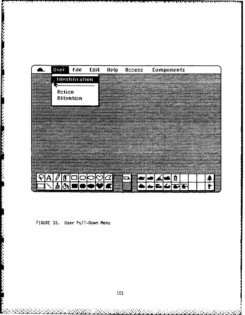
IFile Ecit Help Access Comnponents
.. .Ao ... .... .........
*~~.. FIUR 33.. Usr.ul-ow.Mn
... - - - -
. .. . ...
S.l o
-10----1..

W;S W
AL File Edit Help Rccess Components~~ ............. ..... ..........~~~ . . . ..........
S.. .... . ......... ....... .
.... 9A~A'E. .........f
.....S.. . ~ - ---

. I-.m
File Edit Help Access Components..... ...... ..::.... . . -......
.... ............ . . . . .......... . .... ........... . ...... . ... .
.u~ . . ........
.... . ...... ~ m ..... m 4. ~ .- .:.... .:.4:2 4
......... .. = = .... .- :: . ....
........................... u~s~m:.,.:us~~n :::::n f..f..U..........:: s~uu . ............. n .... . ::::I .... . .......
~~------- - -
FIGURE. 35 Imroe ID Dialog.
103oer10

AL User File Edit Help Access Componentsa
. ...... ,uw:j... ........ :.....: Template Editor
224L .4 2U~~~ 2U~ ..UUU~222UL. ... 2U?222..... .2 .....~. :2:,.22r.::2:h2us2UU .?2~ ......
... 2~n. .f ... 4 ..... ??fU2r.2?2?2722UUtflUUU2f:*U
=93L4: . .. . 25:~m2UrU:U UU.2UUUU U_____________________ U? mr. ......... . .......
2?? . U22UUUU22U2~~~~~ .2U U 2 U : U U .............. .4. .
* ..........
2zz~**UU~z2222 2U aU r2..u~2U U22rL...rnUU U2.4v~...... 2. .... . ...... .2... ....... . .. ...... . ......
r~ ~~~~ .2~ .......~. .2. U.. .:~:? ?? r.... . ...... ......... .:2 ... l .??........
. . ........ . ..... - ------
~UU? U....... ..2 .U . .2 . .......
4 .42UU322~U2 UUUS4UU.uUUU2U2Um2UU 22U:2U2U ? .. 1............2 2UU ...... UU.. On ........ ........... .. .. U ~ :
-----------nU 2 U? 2 U 2U U 2-- ,.4U :.2....2 :::2 UU 2 -2 ......
........... ..
__ User File Edit Help Access Components
... ...... __......_...__...._.. ......._...__... Tem plate Editor
SsSS~an~u~lr~u. .s~stSS ~ . ....l.tffn n . ...... :rtr:n .u:S f..... . ... .......... ..USU~f
EIER i..:.:..4:::-:::t::
OpenChange Priority or Access...........
..........r"=UD elete a UserList Users Cne
. . .. ......
.. ... ...
... . ................................ .......... .
.A~U .~ ..........
* ~ ~~~~~~ FIGURE. 37 AcesCnrl.ilgMn
.. . ... .. . ..
....... ..~ ... .. . ~*~I . . . . . . . ... ~... .. ..

Ah- Use Fil Edit Help .cces Components
.. ............ .... .... .. ........... ..................................... ....................... . ........n= ;;n............ ....I..... ........""nnnn=;=nn=: ....
........ .NEW USER:
N__ N E I n ... ....10D # .... .- ..........PRIORITY:...
0T~?EO OSQUAD.-......--..-.--~.iii.i:~iiiii~i~ii~ii-~ 0 TAIN LT. E INDIIDUA
TYP ECHLO
tuni iiuu~nhsuhnrhusn uiuzn i~ssrtiitsit::~iiii~fiinn::it~ai ii.. i iis tir 2.. 5 5.. ... =n
0 MISION 0 BRTRL ON .Mnn==E1:K --- ------
FIUR 38. New UserFT DialogR
106. ... ....
BRILL LRTO2

enable a Super User to modify the way that the Translator modifies thisinformation. The system also includes an "intelligent" Checker, which checksthe input information and the information placed in reports. The TemplateEditor enables the priority user to modify the nature of this "intelligence"by changing the expert model included to reflect the latest changes indoctrine. The Template Editor will also enable the priority user to changethe Guidance and Instruction provided from the HELP option on the menu bar.The Template Editor will enable the system to remain current and to bemodified to reflect changes in the way training is conducted without making itnecessary to make changes in the software and hardware comprising the CAPSsystem.
Once the user has been identified to the system, the other menu items becomeavailable for the user. To begin work on a document the user must first setthe proper access using the ACCESS option from the menu bar. Selecting ACCESSshows the pull-down menu sh6w'in Figure 39. Only those items to whichE-ieuser has authorized access will be available. The top set of items indicatethe type of document to be used; the bottom set of items indicate the Echelonlevel of this document. The check marks indicate the current selection.
Having selected the appropriate access, the next step for the user is to openthe document for work. The user selects Open from the FILE pull-down menu, asshown in Figure 40. A number of other co6venient facili'tes are available on
the FILE pull-down menu. The Save command enables the user to save the resultof mo'6aications in the documeWn-f-that is currently being created or modified.CAPS will have an automatic back up system that will always keep the new
* document or document modification, as well as the past two versions of thedocument. The Save As... command enables the user to save a temporary versionof the document while work is in progress. This command does not allow theuser to create alternate versions of a given document as part of the permanentdatabase, but does enable the user to create working versions of a givendocument while modifications are in progress rather than leaving the databasein a partially modified state. In other words, the user can call up adocument from the database, use the Save As... command to create a temporaryfile while modifications are in progress. Then when the modifications arecomplete and approved by the appropriate authority, the temporary file can beused to replace the current version of the permanent file.
The Print command allows the user to print the current version of thedocumen-t. The New command allows the user to create temporary files asnecessary but wfT-not allow such a temporary file to be saved as a permanentfile.
Selecting Open command from the FILE pull-down menu provides the dialog boxshown in F-igure 41, which lists aTT-of the documents of the type and echelonselected. With this dialog, the user can select an Input format for thedocument or a Report format. The Input format is likeTatabase requestingspecific inform o-n from the user so that the computer can construct thereport from the information provided. There will be unique input formats foreach of the document types in the system. These will be forms on the screenthat require the user to supply the necessary information. Redundantinformation that can be generated by the system will be provided
107 I.-. - . .- , -. .. . , . .. ,. , ... . ...- .. . ." . . . . . . , .-.. .....- . * . . . .
F .S.I*.*..*" .... . %** ", , "; ,,,

AL User File Edit Help 'components
4'Mission2=__r_____ U. Training EHercise .......
=MU Triln Literature
____________ Batafc-n."e £ndian -Iaf f _
_________ 4Company/Command______ I Platoon/Leader
..... Squad/Leader
Ull...........1f~f;.U~un.l.:...nns
_____ _____ _____ _____ _____ ____ruL.................s:::
.... ______________ .S. .......- U U.J:_________~.
S~~~~~.. .... .U.U :..l;U .........~U-- ...
.= .:: . . .....
... ... .. ... .. ........................................ ....... ..............................

a. User Edit Help Aiccess Components
. . c ; ....... N e .t ............
urnni...nu...
,..~~~ .n.. ............r-u
.~~J.Ope 02 .t .f==~f~ .f.= ***= 4 . . . . . . * ........ .nt~t fi l..........f.tll..
_______________~~~~~~~~~~~~~~~~ .L..sL....tuttltttifflttittft. t mn h n.tttt t. .t t............
FIGURE~.... 40 Fie.ul-ow.Mn
Prin
Qut....4 .......
109.. .

~ ~ ~ ~ ~ ~ ~ ~ ~ ~ ~ ~ ~ ~ ~ v .I7~ --- . ..- - , - C .--- - -- - . .- .7 V.-
a- User Edit Help Access Components. ... ..... .......
D efense .H ..st .u............. .. .....ow r Pa s g ...... ......
Documen Delbeat Attack=9099 Delierae Defey M
ReliefEInhPlac
.... QAup an EDOe ...~t HiDeliberat Rtta
- ~~ FIGURE. 41.. Duentielaec Dialgen
4W.
.. . . .* . ........ --- --- --

automatically. The exact format for these input forms will be designed aspart of the system design at a later time. The user selects a document forwork by clicking the name and then clicking the Open box. The selecteddocument appears on the screen in an open Document Window, as shown in Figure42. Note that the illustrated document contains both graphic and texti nformat ion.
The Report format shows the docU.;ient as it will appear in the training
liter-atre being prepared. The Input format assists the user by providingguidance as to what is required Tii-after the user has input the necessaryinformation the Translator function converts this input into a Report format.In Report format, the user can edit the document like any other document.
Edit commands are available under the EDIT pull-down menu, shown in Figure 43.(Note that the pull-down menu is superimposed over any existing information onthe screen, in this case the open document.) The Copy, Cut, and Paste enablethe user to move blocks of text or graphics from onedo-u-ent to another orfrom one section of a document to another.
A clipboard holds information from the last cut or copy until it is pasted.The system will also have a note pad where the user can keep memos tohim/herself. The system will also have a scrapbook where a series of figuresor pieces of text can be kept for convenient access when creating or modifyinga document.
The Undo enables the user to abort the last operation. Show Clipboard enablesthe 7ser to examine the last item cut or copied. As with all other CAPS menufunctions, these functions will be available from the keyboard, as well asfrom the Edit menu.
The EDIT menu also includes some special functions that enable it to act likea cominied word processor (writing) and graphics processor (drawing). TheFont option enables the user to select from the dialog box shown in Figure 44.TFe-user can select the type, size, and style of font. A variety of fonts,sizes, and styles can be used on any document as required.
The Graphics option is a toggle that displays the graphics menu and iconoptions at the bottom of the user's screen. The left set of options includethe lasso for moving items without the background, the selection rectangle formoving-- ems with the background, the letter for selecting text from graphicsmode, the line segment, a pencil, a paint brush (with various sizes), thespray can, anT the paint bucet to fill areas. iThe shape drawing functions arealso included in the left set of options. The items on the right have twomodes: pattern mode and icon mode. In pattern mode (selected by clicking thepattern box in the middle) a variety of fill patterns is displayed, as shownin Figure 45. In Icon mode, the boxes contain commonly used picturesnecessary for diagraming battle plans and other training information. Thesecan be selected by dragging the icon to the document. They can be enlarged ormade smaller by the selection rectangle. There may be several icon menusselected by double cllcKing tne icon selection box.
-"" ' "-'. ".'",'""'"- - "= "".'" : " -:, '"."-'" . ,,: . " ". -'- . -*.*%** . : '- ..- .. . ;- * ., *.- - . .-- -. .-. ..-'. :--.

AL User File Edit Help ficcess Components
Q MODING WITH TANKS ____DRILL PLATOON
PLPS~PL
N2
F igure I F igure 2
ACT IO"lS/STAINDRDS
1. Fol lowing tanks on l ine (fig 1) used when allI-round protectionis needed.
a.Platoon leadwrs BIFU is the base; other BIF~s guide on
*b. The platoon leader directs each B1F4) to follow a particular §L
tank to control movement left or, right......
........... .... . .~...............

'is - - - 77F. I-r - . r
*.- User File Help Rccess Components
0 'lOUING UndoLROO
Show ClipboardFont D
I.rphc Folwn aiwe al l-round protection
needed.Side-hg-Side
a. Platoon Ie Page Right other BIFVs guide onit. Page Left
*b. The platoail .FV to follow a particulartank to control movemnt left or right.
T , , 4 T h e 9 l l* k r I ~ I ~ . ~ ~ ~ i m n - ~ n i u m ~ h
...... ....................... ....
FIGUR 43. Edit Pul-owMn
113

* User File Help Access Components
MM0 O1 Character Formats I hE PLATOON =Style F
0PlainleHt Cace,_____ 0 Bold 2__
'U:O taicPosition -20 Underline @NormalO ONEQDIX 0 superscript ....
1. Fol lowi QrxJ~p 0Susrp protection
a. Plao Font Name: ide onit.Chicago 9 10' Font*b The p veGeneua I? jSize: particulartan t ~Monaco 14
2 HIM
FIGURE 44. Font Dialog
114
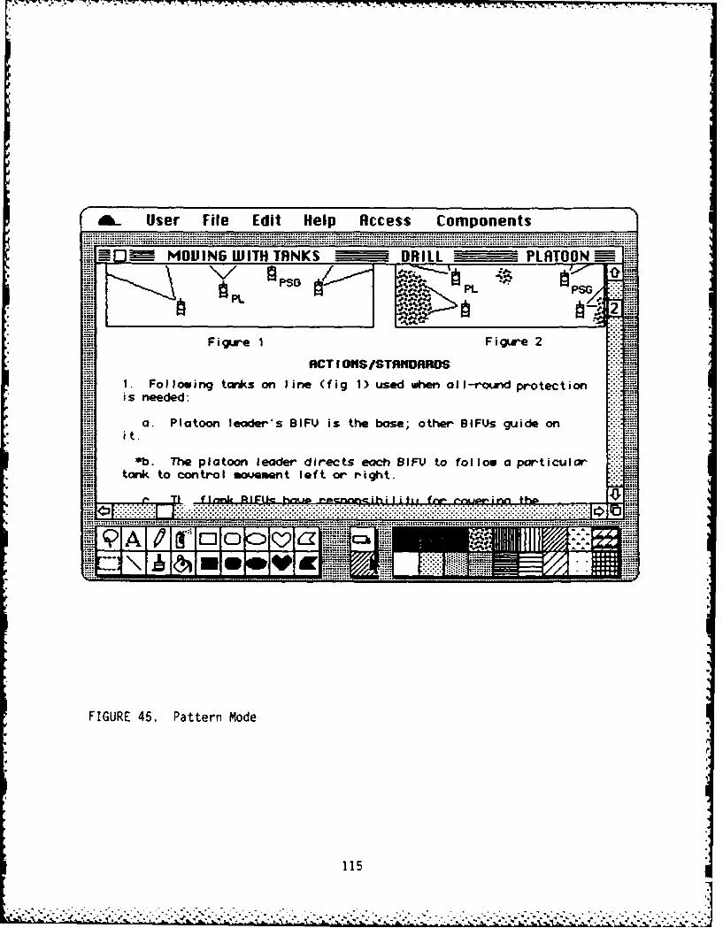
£. User File Edit Help Access Components
NIOIJMQING WITH TANKS ____DRILL _ ___PLATOON
PL0PSGPL
F igure 1 gr
ACT IONS/STRfIDAROS
1. Following tanks on line (fig 1) used when all-round protectionis needed:
a. Platoon leader's BIFU is the base; other BIF~s guide on
it..*b. The platoon leader directs each BiFLI to fol low a particular
tank to con trolI movemen t leQf t or r igh t.
.. ..- .. ............. ..... .... . ............. .-~~.... ....... * . .......... .... ~ ~ ~ 2a

The CAPS system will allow the user to open as many documents as may benecessary to enable the user to work on more than one document at a time andto cut and paste between documents without going through the scrap book.(There will probably be some limit on the number of open documents but it willbe sufficient to enable the user to use the system efficiently.) The EDITmenu includes a special feature which allows the user to either overTa7document on the same screen or to place open documents side-by-side. In theSide-by-Side mode, opening a second document places it to the right of thecurrent ocument by scrolling the entire screen. The Page Right and Page Leftcommands enable the user to scroll the various open documents and to nave eachoccupy the entire screen. In either overlay or side-by-side mode, the usercan change the size of a given document as necessary.
The utility options are available from the CAPS pull-down menu. As shown inFigure 46. These include the Scrapbook, the Note Pad, Calculator, Calendar,and the ability to adjust the system for personnel use via the Control Panel.
The CAPS system will be designed for the experienced user and thus efficientto use. For the less experienced user, the HELP pull-down menu is available.As shown in Figure 47, four levels of on-line1help are proposed. Guidanceprovides a set of menu choices for the user in the form of question decisontrees to enable the user to be led to provide the necessary information intothe input forms. This option is a toggle which is either switched on or offas the user may desire. When Guidance is ON, the user is provided consider-able information to assist him/her by supplying the necessary information.The exact form of this assistance will be developed as part of the formaldesign of the CAPS system.
The Instruction option is a form of hypertext. The user can requestInstruction for any item or for an entire form or document. The system thenopens a Instruction window that tutors the user in the background and theinformation requested. This help accompanies the document being developed ina side-by-side or overlay window so that the user can move easily between thehelp and the application.
The Doctrine/Regulations option is also a form of hypertext, which shows theuser ail of the doctrine and regulations pertinent to the item(s) shown in theactive Document window.
The Roadmap option is a graphic representation of the underlying CAPSdatabase, which shows the user which document(s) are currently being modifiedand where these documents appear in the overall ARTEP database. The actualcontent of the HELP options will be developed as part of the formal systemdesign.
The COMPONENT pull-down menu, shown in Figure 48, is the way that the usergains access to the cross reference matrices, described earlier (CAPS DataRepresentation). By selecting this item, a user can determine the locationand composition of any training document that may be under consideration. Newtraining documents can only be added to the system by first locating theappropriate location for the new document in the component matrix and adding aname and identification number for this new component. The component will
116.1

User File Edit Help Access ComponentsRhout CAPS -
........WITH TANKS ____DRILL ____PLATOON
Scrapbook / L WAflarm Clock ANote Pad ______ ~Calculator IFigr
* Calendar RCTIO#IS/STAPIDAROSKe ap nks on i ne (f ig I) used when aoIlI-roun-d pro tec t ion
Control Panela. Platoon leader's BIFU is the base; other BIF~s guide on
it.*b. The platoon leader directs each BJFU to follow a particular
tank to control movement left or right.
................ ......................... ............ ................ .......

*. User File Edit R ccess Components
_0 W~OING WITH TN ruiHc PLRTOONInstruction
PL Doctrine/Regulations
1. Following tanks on l ine (fig 1) used w m all I-round pro tec t ion
a. Platoon leader's BIFV is the base; other BIF~s guide on
*b. The platoon leader directs each BIF) to follow a particulartank to con troli movemen t leaf t or r igh t.
4.4................................................ ............. ..... *........ .................. ........ X.........................................................................
.... y .. ....
FIGURE 47. Help Pull-Down Menu
1 18

Ak. User File Edit Help Access 11110V
OpenO ~MOUING WITH TQNKS-\/ n__ /
PSG Battalion MissionCompanW Mission
Fig~re 1Squad MissionACT I OHiS
Battalion Collectiue Tasks1. Following tanks on line (fig 1) Comn-tfTskis needed:Comn-tfTak
Companu Collective Tasksa. Platoon leader's BIFV is the Comnbak
IPlatoon Collective Tasks*b. The platoon leader directs emc fPlatoon Leader Tasks
tank to control movement left or rig qudCllcie ak
I* f~o .I U Pji Squad Leader Tasks- -- .. Indiuidual Tasks
FIGURE 48. Component Pull-Down Menu
119

then be available to Open from the FILE pull-down menu. Old trainingdocuments can only be de-eted from the -system by first locating the documentin the cross reference matrices and eliminating its title.
The components of the system are all components of training missions. To usethis menu, the user must first select the echelon of the mission desired. Thesystem defaults to the mission corresponding to the current document. Adifferent mission level can be selected by clicking the appropriate missionlevel on the COMPONENTS menu. The user then selects the amount of detaildesired from the lower part of the COMPONENTS menu. The available choices aredetermined by selection of the mission. The available mission level isdetermined by the user access and priority. Only those options below theselected mission are available to the user. The user can select one or morelevels of detail, provided that to select a lower level the user must alsoselect the higher level. For the menu shown previously in Figure 4-19, themission is "Platoon." Available options include tasks from the PlatoonCollective Tasks level down to Individual Tasks. The User can select anynumber of options from Platoon Collective Tasks down. However, the userc;r.not select Individual Tasks without first selecting Squad Collective Tasks.aimilarly, he cannot select Squad Collective Tasks without first selectingPlatoon Collective Tasks.
The user opens the cross reference document by selecting Open from theCOMPONENT menu. Selecting this option provides a dialog box-as shown inFigiure 49. The names in the scroll box are all of the missions for theechelon shown. This component dialog menu is used to add or delete tasks fromthe system. The user adds a task by inserting the task name andidentification in the appropriate place in the outline. The user deletes atask name by dragging the task name and selecting Cut from the EDIT pull-downmenu. The edit commands are available like any othe'r" document.
A dialog box (not shown) is displayed whenever a user attempts to add ordelete a document. This box asks the user to provide additional authorizationinformation, indicating that there has been an action request and that thisuser is the proper person to make the addition or deletion. The user can onlyadd or delete tasks in those areas where his/her priority allows, but any usercan view the cross reference information for any part of the system. Whenevera task is added or deleted the system sends appropriate Action and Attentionitems down- and up-stream in the system, requesting other users to the prepareor modify all of the training documents affected. New training documents canonly be created by adding tasks to the Components cross reference system.Adding or deleting a task automatically sets Attention items throughout theentire system for all of the training docum.nts that are required to becreated or modified by the addition or deletion of a task.
CAPS Data Representation
The following paragraphs describe the components of the ARTEP database and allof its interrelationships as it is represented to the CAPS user. The readershould understand that this representation is a conceptual data structure andmay not correspond with the way the data are actually stored in the computersystem. This explanation explains data as they exist in the system, not how
120
S: . " . .- - -- , , .- .-, . . .

*__ User File Edit Help Access Components
N0 OUING WITH TANKS DRILL PLATOON
PSO~~ Cornponents of ... -DRILL PLATOON
PCT 218 Camouflage Vehicle & Equipment301 Perform Mlovement Secur ity using Smoke .. ..243 React to Indirect Fires133 Recover your' Tank
78 Reconnoiter an Obstacle X158 Defend Against Air Attack147 Execute Fictions on Contact137 Perform Platoon Fire Distribution &Control76 Execute a Hasty Attack172 By pass an Enemy Position
FIGURE..4.. nent............................ Se e t o Dia og.en
.. .. .. .... .... .... .... .... .... .... ....... .... ... .... ... .... ... .... ... .... ...

data are entered into the system. Note that some of the specific details ofthis data structure may not be completely accurate and will be modified in theimplementation of the system. However, the data structure is sufficientlyaccurate to allow the reader to understand the interactive nature of thissystem.
*i Consider the MOS (Job) x Individual Tasks (MOSxIT) Matrix shown in Figure 50.The Individual Tasks dimension is a list of every soldier task described inthe database. Obviously this is a very long list. Each item in this listcorresponds to a description of a task identified in a individual Front-EndAnalysis or Soldier's Manual. The MOS dimension is a list of every jobspecialty included in the entire database. This is also a very long list. Anentry in the matrix indicates that a given individual task is part of the MOSidentified at the head of the column. This MOS x Individual Task matrix is anindex/cross reference to every Soldier's Manual included in the database. Thebox below the matrix labeled Soldier's Manual indicates that there is a
L Soldier's Manual or part of a Soldier's Manua- associated with every column inthis matrix.
The Squad Collective Tasks x Individual Tasks/Squad Leader Tasks (SCTxIT)
Matrix is shown in Figure 51. The Individual Tasks dimension of this matrix
is the same list as the Individual Tasks dimension of the MOSxIT matrix, shownpreviously in Figure 50. The Squad Leader Tasks dimension of this matrix is acomplete list of every Squad Leader task included in the database. This isalso a very long list. The Squad Collective Tasks dimension is a list ofevery collective task performed by a Squad. Thus, the columns in the matrixeach represent a different Squad Collective Task. An entry in the matrixindicates that the Squad Leader Task or Individual Soldier Task thus marked isincluded in the Squad Collective Task identified at the head of the column.The boxes below the matrix labeled Training and Evaluation Outline (T & EO)and Drill indicate that there is, or should be, a T & EQ and a prescribedDrill described for every Squad Collective Task. These training documents arepart of the database and this matrix is an index/cross reference to thesetraining materials.
Consider the Squad Level Missions x Squad Collective Tasks Matrix, also shownin Figure 51. The Squad Collective Tasks dimension of this matrix is the sameas the Squad Collective Tasks dimension of the SCTxIT Matrix. This is anexhaustive list of every Squad Collective Task. The Squad Level Missions is acomplete list of every Squad Level Mission. An entry in the matrix indicatesthat the Squad Collective Task identified by the row is included in the SquadLevel Mission identified by the column. The box below the matrix labeled STX(Situational Training Exercise) indicates that an STX could be defined f"'-every Squad Level Mission. These STXs are included in the database and thismatrix serves as an index/cross reference for all Squad Level missions andtheir associated training materials.
Next consider the Platoon Collective Tasks x Squad Collective Tasks/PlatoonLeader Tasks (PCTxSCT) matrix, shown in Figure 52. The Squad Collective Tasksdimension of this matrix is the same as the Squad Collective Tasks dimensionof the previously described matrices. Platoon Leader Tasks are added to thisdimension. An entry in the matrix indicates that a given Squad Collective
122r.

Comfplete list ofall floss.
Mos (JOB)123 n
__ * Uindi'watts that thisindividual task is
ft III Lnlue i 1S
NUOTE: Indtvidual tasks can be grouped into squad collective tasks orinto MOS catagorles. These groupings may be different.
FIGURE 50. MOS (Job) x Individual (MOSxIT) Matrix
123

1 17
Each cell in P/S matrixis Colum in S/I matrix.
Complete ist of allSquad collective Complete ist of alltasks. Squad missions.
SQUAD COLLECT NE TASKS123 n
camens tat squad
leader task included ASQU LEVEL MISSIONS
leadear task includkedVI
(a in squad colnective 3-- letas ts.in""!!I I I vda tas rnlme I I4k I_.._ "
0luded in squad missYin.
Drills can be defined foreach Squad collective STX tncludes how to
task. train information addedto set of squad colective
Cmplist of tasks for a given mission.all Wind idual tasks.
FIGURE 51. Soldier's Manual x Squad Collective Task x Individual
Task (SMxSCTxIT) Matrix
124
. . . . .. . . . .- -
n .. i

Each cell C /P matri x*is cobwm inP/Smatrbc.
comnplte list of aUlplatoon collective Complete list of alltask. Platoon level missions.
PL ATOON4 COLLECTIVE TASKS123 ... n PLATOON LEVEL MISSIONSoememo platoon leader 12n
!c3 task inokdedin platoon .
Q. -j I--collective task. 01LII
tafskmtin 'dddto'e f- Tl atoo sks ior paoin msin
FIUR 52clto iso lto ollective Task x qa
Colctv Tasks tiv (xPtsk tinc x a
125isin
STX nckies hw totrai
information ~ ~ ade.osto
plaoo tak fo a gie mission
Task or a given Platoon Leader Task is included in the Platoon Collective Taskidentified at the head of the column. The boxes labeled T&EO and DRILLSindicate that the database includes a T&EO and a prescription-for a FTT-forevery Platoon Collective Task. This matrix serves as an index/cross referencefor all Platoon Collective Tasks and the associated training materials. Notethat each cell in this matrix consists of a Squad Collective Task column fromthe SCTxIT matrix, shown previously in Figure 51.
The Platoon Level Missions x Platoon Collective Tasks Matrix is also shown inFigure 52. The Platoon Collective Tasks dimension of this matrix is the sameas the Platoon Collective Tasks dimension of the previously described matrix.An entry in this matrix indicates that the Platoon Collective Task identifiedby the row is required for the Platoon Level Mission identified by the column.The box labeled STX indicates that a situational training exercise can andshould be descriffe"T for every Platoon Level Mission identified by the matrix.This matrix serves as an index/cross reference for all Platoon Level Missionsand their associated training materials.
The Company Collective Tasks x Platoon Collective Tasks/Command Tasks(CCTxPCT) Matrix is shown in Figure 53. The Platoon Collective Tasksdimension of this matrix is the same as the Platoon Collective Tasks dimensionof the previously described matrices. Command Tasks are added to thisdimension. An entry in the matrix indicates that a given Platoon CollectiveTask or a given Command Task is included in the Company Collective Taskidentified at the head of the column. This matrix serves as an index/crossreference for all Company Collective Tasks. Note that each cell in thismatrix consists of a Platoon Collective Task column from the PCTxSCT matrix,shown previously in Figure 52.
The Company Level Missions x Company Collective Tasks Matrix is also shown nFigure 53. The Company Collective Tasks dimension of this matrix is the sameas the Company Collective Tasks dimension of the previously described matrix.An entry in this matrix indicates that the Company Collective Task identifiedby the row is required for the Company Level Mission identified by the column.The box labeled FTX indicates that a Field Training Exercise can and should bedescribed for every Company Level Mission identified by the matrix. Thismatrix serves as an index/cross reference for all Company Level Missions andtheir associated training materials.
The Battalion Collective Tasks x Company Collective Tasks/Command/Staff Tasks(BCTxCCT) Matrix is shown in Figure 54. The Company Collective Tasksdimension of this matrix is the same as the Company Collective Tasks dimensionof the previously described matrices. Command/Staff Tasks are added to thisdimension. An entry in the matrix indicates that a given Company CollectiveTask or a given Command/Staff Task is included in the Battalion Collective
. Task identified at the head of the column. This matrix serves as anindex/cross reference for all Battalion Collective Tasks. Note that each cellin this matrix consists of a Company Collective Task column from the CCTxSCTmatrix, shown previously in Figure 53.
126....... .-. .*..-

Each cell in B/C matrixis cokwm in C/P matrix.
I ~complete list of allCompamns collee~ttye tasks. Complete list of all
Company le'rei missions.
COW? ANY COLLECT IYE TASKS
12 .. COMPANY LEVEL MISSNJW4
1~ means that Platoon 0 nwcoe2v task is part of
coomn collective task.
u .- IIIIL
4Cn means that CPlana.collective task is part of
Comnpanyj mission.
FIGURE 53. Company Mission x Company Collective Task x PlatoonCollective Task (CMxCCTxPCT) Matrix
127

.. -.. L - -. , -... . - , - - . : - - - . -i r r, ,,'.r% v xias... 1 r r . ,..
Complete list of allBattalion collective tasks.
Complete list of allBattalion level missions.
BATTALION COLLECTIVE TASKS23I T39:1= N means that cmea/ BATTALION LEVEL MISSIONS
S _O__ _ II__IIU 123 .t•. n* i stafftask ispart of X
30 _ Battalion collectiye task. 1!
*l means that Compawj z-collective task is part of oBattalion collective task.
II-
Ill ni1E i me an that Battalionoollotiv. task is part of E n
L.) Battalion mission.
FIGURE 54. Battalion Mission x Battalion Collective Taskx Company Collective Task (BMxBCTxCCT) Matrix
128

I - 1 I P -, 91. 91. F
Consider the Battalion Level Missions x Battalion Collective Tasks Matrixshown in Figure 53. The Battalion Collective Tasks dimension of this matrixis the same as the Battalion Collective Tasks dimension of the previouslydescribed matrix. An entry in this matrix indicates that the BattalionCollective Task identified by the row is required for the Battalion LevelMission identified by the column. The box labeled FTX indicates that a FieldTraining Exercise can and should be described forigery Battalion LevelMission identified by the matrix. This matrix serves as an index/crossreference for all Battalion Level Missions and their associated trainingmaterials.
Impact Relationships
Figure 55 is a diagram showing the various components of the ARTEP database.Please note that some of the specific details related to this iterative impactdiagram may be inaccurate and will be modified in the implementation of thesystem. However, the diagram is sufficiently accurate to allow the reader tounderstand the interactive nature of the system.
This diagram explains the interactive and iterative nature of the datastructure. However, the diagram does not attempt to indicate who makes theentries for a given part of the database or how the system alerts a given userthat additional entries need to be made to keep the system up-to-date andcomplete. These concerns will be considered in the next section of thisreport. Since the system is iterative in nature, a complete description ofall the possible interactions is impossible.
The components of the database have been divided into three types: 1) primaryinputs, 2) training materials, and 3) cross reference matrices. The primaryinput components are indicated by the diagonal-strip boxes, the trainingmaterials are indicated by the grey boxes, and the cross reference matrices bythe white boxes. The solid arrows show the primary impact paths while thedotted arrows show secondary impact paths. A primary impact path is one hatresults from a change in one of the primary input components. This changerequires updating of the components "down stream" from where the change wasmade. The priority system (described previously) would require, via theAction List, that the changes resulting from primary impact be made.
A secondary impact path is one that results from a change in the trainingmaterials that may suggest the need for the addition of an individual task, aleader or command task, or even a change in doctrine. Since secondary impactsmove up the priority system, the implied changes in higher priority componentscan only be suggested (via the Attention List) and the actual change must bemade by a user with the appropriate priority to make that change.
The system can be entered at any of the primary inputs (diagonal-strip boxes)or training inputs (grey boxes) indicated in Figure 55. The followingdescriptions indicate the iterations required from a change in a primary inputcomponent and also the iterations that may result from a change in a traininginput component.
129
?-..-. -. . * ..--.. .... .. . - . ,+ ,. . 4....- ......... .. . . ..

xCCT US Do
. j .rll j:;
ItrlCCTKeg:
Primar i.~ISxNCn
~i!~iiii~ii~iL~;i!Jii TTin i
RNN
FIGRE55 CPSItraiv Ipat iara
SM S~xST d 130
x IT < - - - - -. -

Primary Data Entry. A primary purpose of the ARTEP program is to provideadequate training materials to guide the execution of training exercises. Thefoundation of the program is the definition of training missions that preparethe fighting units to work together as a team in the implementation of thelatest in strategy and equipment utilization. Changes in Doctrine and/or theequipment available to fight affect the way missions can be carried out andthe strategies that might be appropriate. The tremendous value of the CAPSsystem is the ability for a change to iterate through the entire system, thusassuring that the training guidance provided is current and consistent withthe most current doctrine.
Primary entry to the system can occur by defining training missions at anyechelon. Missions for higher echelons have more potential impact than dochanges in missions for lower echelons. To illustrate the iterative changesthat this system makes possible, consider a change in a mission for theCompany level. The user enters the CAPS system at component CM (CompanyMission). The required entry is to define or redefine a Company level missionin accordance with a change in doctrine, strategy, or equipment availability.This mission description is part of the CAPS database.
A change in a mission statement iterates through the entire system as follows:A change in a Company level mission may require changes in one or more of thePlatoon level missions that may be part of the larger mission. This impact isindicated in Figure 55 by the solid arrow from CM to PM. Recommendations forsuch changes are sent to the Platoon level mission component for action by theuser who will modify platoon level missions. (This could be the same user, inwhich case his Action List would now contain the message to make theappropriate changes in the Platoon level missions.) The resulting change in aplatoon level mission may require changes in one or more of the squad levelmissions which may be part of the platoon level mission. This impact isindicated in Figure 55 by the solid arrow from PM to SM. Action itemsinitiated by any change remain in the system until the change has been made.
Returning to the initial change, a change in a Company level mission requiresthe user to update the Company Level Mission x Company Collective Tasks crossreference matrix. A change in a Company level mission may also require theaddition, deletion, or modification of one or more Platoon Collective Tasks orPlatoon Leader Tasks that comprise the Company Collective Tasks, which arerequired for the mission. In other words, a change may be required in theCompany Collective Tasks x Platoon Collective Tasks/Platoon Leader Tasksmatrix. This impact is indicated in Figure 55 by the solid arrow from CM toCMxCCTxPCT. The system prompts for the necessary changes to the matrix.
Changes in the CMxCCTxPCT matrix may iterate throughout the entire system. Forexample, a change in a Platoon Collective Task may require the addition,deletion, or modification of one or more Squad Collective Tasks which comprisethe Platoon Collective task. This would require a change in the PlatoonCollective Tasks x Squad Collective Tasks/Squad Leader Tasks matrix. Thisimpact is shown in Figure 55 by the solid arrow from CMxCCTxPCT to PMxPCTxSCT.A change in a Squad Collective Task may require the addition, deletion, ormodification of one or more Individual Tasks which comprise the SquadCollective Task. This would require a change in the Squad Collective x
131

Individual Task matrix. This impact is shown in Figure 55 by the solid arrowfrom PMxPCTxSCT to SMxSCTxIT. Furthermore, a change in an Individual Task mayrequire the modification of an MIS and resulting changes in the Soldier'sManual which describes this MOS. These impacts are shown in Figure 55 bysolid arrows from SMxSCTxIT to MOSxIT to Soldier's Manuals.
Other iterations are also possible from the change in a Company level mission.Some of these are as follows: Changes in the PMxPCTxSCT matrix may implychanges in platoon level missions. This impact is a secondary impact shown bythe dotted arrow from PMxPCTxSCT to PM. A similar secondary impact on squadlevel missions may also result from subsequent changes in the SMxSCTxIT matrixas shown by the dotted arrow from SMxSCTxIT to SM.
The end result of a mission change is the necessary changes in the trainingmaterials. A change in a Company level mission would have a direct impact onthe preparation of Company level Field Training Exercises, as shown by thearrow from CM to C-FTX. The ripple effect described in the previousparagraphs may result in changes to Platoon Level Situational TrainingExercises, indicated by the solid arrow from PMxPCTxSCT to P-STX, and in SquadLevel Situational Training Exercises, indicated by the solid arrow fromSMxSCTxIT to S-STX.
Other training impacts are changes required in T & EOs and Drills by changesin the PMxPCTxSCT matrix and the SMxSCTxIT matrix. Changes in the Soldier'sManuals resulting from changes of individual tasks have already beenindicated.
A careful study of Figure 55 shows that a change at a higher level may iteratethroughout the entire system. The great advantage of the CAPS system is thateach of these impacts is systematic, is made part of an Action List for anappropriate user, and remains as a flag in the system until an appropriatechange has been made.
Secondary Impacts. Secondary impacts can be side effects of primary changesas indicated above. The other source of secondary impacts comes as a resultof insights gained or inconsistencies observed when a given training exerciseor manual is being prepared. The message concerning this inconsistencyripples *up stream" through the system, setting messages on upstream user'sAttention List. For example, when writing a Soldier's Manual, a user mayrealize that further action is required farther "upstream" and may message theAttention List of a user at PM via the PMxPCTxSCT matrix.
A complete tracing of the iterations caused by a single change are difficultor impossible to trace completely. The previous discussion should besufficient to assist the reader in understanding the iterative nature of thesystem and how the impacts ensure that a change in one part of the systemresults in the necessary and potential changes to other parts of the system.The result is training materials that are always current with the latest indoctrine.
132
* :. . : .. :b . * .. .. * Q

CAPS Database Management System
General Motivation. The preparation of an MTP requires the interaction of theauthor(s) with a large and complex variety of data. These data represents theaccumulated relevant reference information from other Mission Training Plans,basic reference sources (Soldier's Manuals, standards, etc.), the work productfor any previous versions of an MTP undergoing development, along with thecurrent status of the MTP being prepared. Indeed it is likely that more thanone version of an MTP (or parts of an MTP) must be maintained in the systemand that the system undergoing development has several different versions (orlevels of currency).
The system itself must be able to provide support for the management of thediverse versions of documents we have mentioned. It must form an rchivalbase for an MTP once frozen. It also should be capable of imposing structuresso that we can authorize changes to various parts on the basis ofresponsibility, to eliminate the possibility of even inadvertent changes madeby non-authorized personnel.
We also recognize that a wide variety of auxiliary information relating to theproduction process itself will be managed by the underlying computer-basedsystem. Such things as the storage and retrieval of documents relating to thework in progress, and a complete tracking system to manage internaldistribution of drafts, routing of information, and the status of signoffswill be handled.
The best means of accomplishing the task of managing this information isbuilding a superstructure on top of a commercially available, large-scaledatabase management system. By doing so, we can leverage off many of theunderlying features of such a system, including the physical management of thedata and the ability to perform queries (both standardized ones that aresystematically applied to the data to check for consistency, etc. as well asad hoc queries generated interactively during MTP development). Such a systemtypically satisfies our needs in the area of data access protection throughthe use of user names and passwords that will permit and restrict accessormodification of fields as desired. Modern database management systems alsoprovide a wide variety of library and language access methods. This willpermit us to integrate tools and programs from a variety of sources anddisciplines to access and manipulate the data without being restricted to oneparticular language, which would typically occur if the database storage werespecifically done for CAPS itself.
Requirements. As a result of our studies of existing Mission Training Plans,we see that the information is more than standard textual material, itappears that about 50% of the material is textual and the remainder is eithergraphic images in the form of figures or tables and charts. This graphicalinformation, as well as the textual information, is highly variable in lengthand content. It is not at all like the simple data or other disciplines.Hence, we need to maintain, manipulate, cross reference, and correlatesignificantly mixed data representations demanding a highly flexible system.
x V, 133

The prime requirement for storage of the task description information is theability to handle data structures which contain perhaps several thousand rows.Each row contains a relationship between a particular element in a Drill orSTX, etc., and the other elements, such as necessary preconditions,corresponding actions by related groups, references to doctrine, etc.
For example, let us consider the information needed to describe a particularARTEP Task in a form that would be used in preparing the MTP material. Suchan element would comprise at least the following bits of information:
(1) Drill-id: This is the internal reference number (assigned by thesystem in a unique fashion) that is used to relate togetherdifferent elements of an MTP. This number is not used for anyexternal purposes; for these purposes see data elementsARTEP-Task-No or T&EO-Task-No.
This field is a fixed length field containing a large integer orstring.
(2) Description: A particular task has an English languagedescription that categorizes this item in a highly syntatic form;e.g., FORM COLUMN, TAKE ACTION ON CONTACT, etc. Note that thewords and phrases used here come from a small vocabulary and weexpect that CAPS will include input validity checking as well asanalysis of completeness available to check the completeness ofthe MTP.
Note that this field might be several words long and of highlyvariable length.
(3) Echelon: Each task applies only to a particular individual orcollective level. This field is chosen from the small set ofpossibilities; i.e., Battalion, Company, Platoon, Squad.
This field could be compressed into only one byte.
(4) Form of Task: Tasks are referred to by different terminologieslepending on their context. This field contains the officialterm to be used, such as TASK, DRILL, STX, FTX, etc. Note thatalthough these are different types of elements, they share somany other things in common (such as the preceeding fields, etc.)that for the purposes of the internal computer database we arenot making a formal distinction among them, even though oneexists. They are being grouped together because that simplifiesthe handling by the computer system since they share the sameprocessing and storage requirements.
This field is also one of a few special types and could be aninternal number or else a small character string.
134
-7 * * . .. . . . . . . . . . . . . . . . . . .

(5) Reference: Every task is not fully defined in the body of theMTP itself but often the details are found in other material suchas the Soldier's Manuals. Hence, we need a field (or severalelements) that are these reference pointers. They will containstandard reference labels, such as FM-17-19E1/2, which will beprinted in the MTP and looked up by instructors. One form ofcross checking that CAPS should make possible would be to see thecompleteness of MTPs; are all relevant portions of a Field Manualincluded or not? Technically this is part of the CollectiveFront End Analysis and not the actual authoring of the MTP.Nonetheless, it is essential that the database permit such anextension of its usage.
This field is a variable length string; it might be tens orhundreds of characters long.
(6) ARTEP-Task/Mission: Every task belongs to one of the generic setof ARTEP classes; for example, it might be MOVE, DEFEND, orATTACK. (There are also subcategories, such as ATTACK-HASTY, orATTACK-URBAN.) We might create a second field for theARTEP-Subcategory; e.g., HASTY, URBAN, DELIBERATE, etc.
This field can only be filled with one of a small set oflegitimate terminology. Hence, it could be reduced to smallinternal numbers, or else a small set of possible strings.
(7) ARTEP-Task-No: This field will contain the present ARTEP tasknumber (where appropriate) or else other existing relevantdesignators, such as the Soldier's Manual or Field Manual number.This could be something such as 3-IV-1-5 or 171-127-0002.
This field would be a variable le .gth string several tens ofcharacters long.
(8) T&EO-Task-No: This field would contain the present index for anitem, such as Task 147, etc. This field is mostly used for crossreferencing when showing STX-FTX matrices, etc.
This field is typically an integer.
(9) Decay-Factor: Every task (in general) has a decay factorassociated with the frequency of refreshor training needed. Forthe instructor to determine whether sufficient drill and practiceis being given, this decay factor has to be calculated incombination with other decay factors that result from training invarious different contexts. This is another area where thedatabase would be useful in an active fashion, going far beyondthe production of the MTPs, but in their usage by instructors.Using this information, a set of preparations could be evaluatedto see if they are sufficient in training various areas, overtime.
135
7A

This field would be a number relating to the time factor.
(10) Other Fields: It is hard to say at this time all the relevantfields that we might develop from a complete and systematicanalysis of a given MTP. It is fair to say that additionalfields would be useful and there might be several such, eachmultiple variable character strings long.
Thus, we get a picture of a standard record entry for each kind of TASK; it iscomprised of up to several hundred bytes of data. We see that there is a lotof variability in the actual amount of data in use in each particular record.Some will have lots of entries in the reference fields, and others mostly inthe "other" category. Hence, it is a requirement that the system permitrecords that are hundreds of bytes long (and shortly we will see why they mustbe in fact thousands) and also that the system compress out all the unusedspace, or else we will require two or three times the raw storage.
We have made an estimate of the number of entries in a table such this one,and it is several thousand records long.
If we proceed to study the data requirements for descriptions of missions anddrills, we see other types of data elements are required that are notaddressed above. They include both graphics information (see Section 4.1.6)and lengthy textual descriptions. Both of these data types are represented byvery long, variable length strings of data. In the case of pictures, thedescription of a picture is composed of individual elements of primitive form,such as rectangles, circles, connections, shading, etc. Each of theseelements is qualified by the particular size, shape, position, etc. Thisrequires many thousands of bytes to represent a typical tree of tasks or otherobjects such as formations, signals, etc. Similarly, for text we see the needfor sections of text that are as long as a page (or so); this is also as muchas several thousand characters, potentially. Hence, we conclude that onerequirement for the database system is the ability to manage files of up toseveral thousand records, each one potentially variable in width from tens ofcharacters to tens of thousands of characters long.
We also recognize that we cannot, at this time, define all the possible usesof the data, their possible values, nor all the fields that might beappropriate to add to the data once we have them in manageable form. Hence,it is a requirement that there needs to be an ability to add additional fieldsto a record, to adjust the size of a field, and to generally restructure thedatabase without recreating it all, during the lifetime of these data.
As well as recognizing that we cannot anticipate all the possible fields ofdata that the system will evolve to require, we expect this is also true inthe area of database inquiries. The graphical front end will provide for manystandard options for presenting and visualizing the current status of the planbeing developed, but it is clear that there will be many additional ad hocqueries that we cannot even anticipate at this time. This is most certainly astrong requirement during the initial development of the system. It willbecome less critical as the system is rolled out in operational use, but webelieve that because of the radically new set of tools that will evolve only
136

during exposure to the system. Hence, it is a requirement that the underlyingdatabase management system must have a high level (English-lik1e) queryinterface. As well, we believe that the interface must be available from aset of languages, to include at least the following: assembler, C, andPascal.
The design of the system architecture is a series of intelligent front endgraphics-oriented workstations, with a back end database server/machine. Thisstructure imposes an additional requirement on the database management system;namely, that the DBMS must be networkable. A suitable DBMS must be able to besplit into multiple tasks, running on different physical n,achines, which arecommunicating via a high-speed network. We envision this split providing forthe ability of the user stations supplying fair high-level queries (thosedescribed in the previous paragraph), which are sent to the back-endprocessor. This back-end processor has considerably higher performance thanthe workstations and, as well, is the repository of the actual database indisk form. This processor is the place where the locking of the records takesplace during updates, and is used to coordinate the demands of multiple users.Any query will cause activity to take place on this back end machine with theresults (generally now a small subset of the database) to be sent via thehigh-speed network to the individual work stations. During this transfer, thedata may be buffered using some intermediate node file storage, although fromthe logical point of view this is totally transparent.
Our analysis of the nature of the changes to the database for the CAPS systemshows that the development of an MTP is an iterative process that involves acertain amount of "trial and error." That is to say, an author develops oneapproach, then analyses it to see if it meets the requirements and coverage offundamentals. This may result in another attempt at a solution, and so on forseveral cycles. During this process, many related changes are made to thedatabase, which must all be backed out to enter a new approach. It is arequirement that the database system provide "rollback" to a previous statusas a standard underlying feature. As a related matter, the system mustprovide a "commit" facility, which makes the set of changes official in thedatabase and available to other users.
Hierarchical Database Systems. We may be able to best understand the natureof a traditional hierarchical file system by way of an example (taken fromDate). Imagine that we are keeping track of a series of parts that we receiveTiriiI several different suppliers. A given part may come from differentsuppliers, and a given supplier may supply several parts. One way to organizethese data might be to first consider all the different parts. For each partwe can list the part number, part name, part color, part weight, and locationof the part. In addition, for each of these records we must keep track, bymeans of a pointer or a set of pointers linked together, the supplier for thatpart, location of that supplier, quantity of parts we have in stock from thatparticular supplier, etc.
The typical nature of queries made against such a database would be: give methe first part; give me the name of the current part; give me the next part;give me the supplier number of the current part (or the supplier Fecrd ofthat supplier number). To ask a question such as, "Show me all the part
137

numbers of all parts that all the suppliers in Buffalo provide," the data mustbe found by first studying the explicit links that connect together theindividual records. In the case described above, we presumably would searchthrough each of the parts, looking at each of their suppliers, and if thelocation of the supplier was relevant, keep track of the original part number.
On the other hand, one could have organized the data in this example by makinga list of all the suppliers, and then for each of the suppliers keeping a listof pointers to each of the parts they have supplied. If this was the case,the program that was responsible for supplying the answer to the query we areconsidering would be different. It would immediately look at the location ofthe supplier and only then, if in the correct city, make a list of the partnumbers.
This is not a good state of affairs unless we have a very strong reason toprefer one organization over the other. Hierarchical systems force all theprograms that access the data to know quite a bit about the organization ofthose data in the forms of the trees or links between records. It is possibleto apply many well-known techniques of indexing and hashing to make severaldifferent alternative routes through the data relatively more efficient, butthe model of the sequence of records, subrecords, detail records, etc.,permeates the hierarchical system.
Another problem to which most hierarchical systems do not lend themselves toeasy solution is the elimination of redundant information. In the exampleabove, once we have defined the structure, if we choose to keep the supplierlocation in the supplier record, then the first method results in many copiesof this information. When the supplier moves to a new city, the change mustbe made in many places. It is possible to keep a separate record for eachsupplier and look up the location there, but this is no longer a strictlyhierarchical tree system. Instead, if we try to make this change onceprograms have been written to each datum (or to suddenly add multiplelocations to a given vendor), it becomes necessary to find and modify all therelevant programs.
In addition to the lack of symmetry in hierarchical database systems and theproblems associated with avoiding redundant information, experience has shownthat making changes (e.g., insertions, deletions, new record types, increasingthe size, squeezing out the "dead space," reorganizing the data for moreefficient searches, etc,) are extremely difficult to do well, especially whenthe timing of making some of these changes must be synchronized withsimultaneous program changes.
Yet hierarchical systems are very natural models to use for data that arisefrom the "real world." Mission Training Plans are organized into volumes atlevels Battalion, Company, Platoon, etc. Then each of these is organized intochapters, and so on. This is the natural way that we organize information inour physical filing cabinets and is the way we tend to initially present theprinted version of the Training Plans. Hence, there is a strong naturaltendency to view the data that this particular database (the CAPS Database)must handle as strongly hierarchical in nature.
138
* ~V. -*Il T.. . . . . . . . . . . . . . . . . . . . . . .
Relational Database Systems. Relational database systems provide for a greatdeal of shielding of the internal details of the management of the actual dataand allow the programs to deal with the data and data relationships from amore abstract position. Let us reconsider the simple example of the lastsection from the perspective of a relational system.
In a relational database system, we refer to a collection of records as atwo-dimensional table, known as a "relation." A collection of several tablestypically comprises one "file." Each of the "rows" of the table correspondsto the record that we discussed in the previous section. The onlyrelationship between data that appears in different tables is through valuesthat are in common between these tables; this might be elements such as "partnumber," "supplier name," etc.
A simple relational database, consisting of three relations, is shown inFigure 56. In this case, we would probably organize our example by providingone table for each vendor number, name, and city. (Note there is norestriction that there must be only one entry for a given vendor number;hence, multiple cities might be allowed. Of course, we could also disallowsuch a construct if that is never possible.) Notice that the name andlocation of a vendor (potentially long address strings which occupy lots ofdisk space) appears only once, thereby occupying minimal storage and alterablein one location. A separate table would list the part number and part name.
Finally, we would build a third table that has entries with three elements:the part number, vendor number, and on-hand quantity that corresponds to thatpair. Notice that all the links between the first two tables is done via thethird. But a relational system does not even require the user to be aware ofthat matter. It will be able to provide the answer to queries such as "listthe parts that are supplied by suppliers in Buffalo" by having the databasesystem handle the necessary linking of the information. Of course, it isstill possible to make significant differences in the amount of time it takesto answer such a query by reorganizing the data or its sequencing. In thiscase, t e linking table could be organized along the sequence of suppliernumber, or part numbers, or perhaps other techniques (hashing) that handleboth might be selected. But in a relational system such choices do not affectthe ability to get results or the programs that access such results. They dochange the speed by which the results become available.
The Choice of a Relational Model for CAPS. The analysis of the ARTEP trainingmaterial has indicated the great amount of structure contained in theinformation. There is also a large amount of parallelism between theinformation and organization at various levels or echelons. In fact, it isessential for the authors to maintain this parallelism, since activities ateach level must be coordinated. While we are not saying that higher-leveltasks are simply aggregates of lower-level ones, they certainly require orimply certain actions at lower levels. Squad activities cannot take placewithout individual soldier action, etc.
Today's training materials present a view of the underlying CAPS dataaccording to certain traditional methods. The charts that display the taskswhich comprise an STX are found to be effective in communicating that
139

Vendor Vendor City StateNo. Name
045981 Good Wines, Ltd. San Francisco CA3379B0 Little Computers Manassas VA
125065 AeroSpace Company Los Angeles CA
857320 Rags & Such New York NYVendor Relation
Part Part
No. Name
C667 Floppy Disk
872 Ribbon Cable
H9ox Print Head
Part Relation
Vendor PartNo. No. Quantity
097564 C667 100
337980 AO 12 440
125065 A075 25
337980 H90x 100
045981 AO 12 123
887320 C667 224
Vendor-Part Relation
FIGURE 56. A Small Relational Database
140
I..," "-" " -"-" ."- N-."- .-"-"- ."-.-." '.-. . '-.- --.- . ...-. -.- . -. - . . -. . ;, ""-, " -"i. .- -

information. STX-to-FTX matrices are another tool that is useful instructuring exercises and training, but are really just another way of lookingat information that is already contained elsewhere in the MTPs. In fact, weknow that it is probable that despite efforts at correctness, these two waysof-presenting the relationship may have errors or oversights that we wouldlike to eliminate. A relational database provides the natural mechanism todeal with such problems. The data themselves are entered in only one form.Any change to that information will automatically propagate itself to thedifferent ways that this information is used by authors and in the actualmanuals themselves. As well, we can more easily limit the authorization tochange information in ways that model these authorities.
Let us look at the example we have been using to understand this point. In arelational model, we can give permission to modify the part number table toone individual, permission to modify or add to the supplier table to a secondindividual, and the third table which describes the actual inventory of partsin stock to a person with different responsibility or authority. Trying to dothis in a hierarchical system is not very practical.
In the case of the data needed for the CAPS system, there are great advantagesderived from allowing the links between data to arise from the datathemselves. This will permit us to load up the database starting from "raw"documents, and then gradually produce simpler and simpler tables from thedata. By way of this example, we might initially enter the information byexplicitly naming each supplier, supplier location, etc. Then, using the adhoc query access of a relational DBMS, we could request things such as "a listof all supplier names, sorted." A quick scan over this list will quicklyidentify things such as misspellings. Once this sort of thing is cleaned up,we can build a table of supplier information, etc. As well, we can see that arelational database system makes it quite straightforward to add additionalfields to existing data. This is far from simple for a hierarchical model inmost typical systems.
Comparison between Oracle and Ingres for use as CAPS Database System
A detailed study has been made of the features of the Oracle database system,and the Ingres database system, to determine whether one was stronglypreferred over the other, or not. Given the requirements of the CAPS database(as described elsewhere in this report), it is concluded that Oracle ispreferrable over Ingres; however, Ingres is marginally acceptable. Oracleprovides significant superiority in the following areas:
(1) Number of elements and total record size permitted(2) Miscellaneous features
The following is an elaboration of the features that are of significantadvantage to CAPS; most others are sufficiently close or irrelevant to CAPSthat they are not mentioned. For example, the price of the two systems foruse on a multiuser minisystem (such as a VAX 11/750) are quite similar.Report writing capabilities, and the ability to access from high levellanguages are also both quite sufficient for CAPS purposes.
141
.
o- .- - - . - ." . .* -°.% - . . ° . + " o % %"oS. . .° .- .'- °.+ .°'° - i * o ° ° . -"."....o

Number of Elements and Total Record Size Permitted. Each record of an Ingresdatabase is composed of up to 127 columns. Each column is a particulardatatype, numeric or character. Numeric fields take up fixed length (1, 2 or4 byte integers, 4 or 8 byte floating point numbers); character strings may beas long as 2,000 characters long.
The total length of all fields together must add up to no more than the 2,000character maximum, and this is true despite whether the fields are actuallypresent or have NULL values. Ingres does not compress space out of unusedfields (such as numerics) unless specifically set up to do this, and willremove only trailing blanks in character fields.
The microcomputer version of Ingres, Microlngres, (which might be used on thefront end 68000-based workstations) is even more restrictive on record sizes;it restricts the number of columns to 49 instead of 127, and the rows to 1,006characters wide instead of 2,000. It should be noted that if the databasecode is to be executed locally for certain operations, the database that runsin the central host would then also need to be limited to these latternumbers, which is an unacceptable limitation for CAPS.
Oracle permits each table to have up to 254 columns. Each element may be oftype DATE (7 bytes long), NUMBER (m,n) (variable length number, up to mdecimals digits long, with n decimal places), CHAR(n) (character string up tomaximum length 240 characters), and one entry may be of type LONG, which is avariable length string up to 65,500 bytes long. There is no fixed maximumbased on the sum of the lengths; it is legal to have 100 fields each of 200characters if desired.
The Oracle database system uses no file storage for missing fields, hence itcan compact data far better than Ingres. The microcomputer version of Oracleis fully compatible with the minicomputer version, and is not a subset.
Comparing these two alternatives, one may conclude that Oracle issignificantly easier to use for the CAPS project. The most significant areaof distinction derives from the 2000 character per row limit in Ingres (evenless in Microlngres). In CAPS, it will be essential to keep large (especiallyfree-form text or graphics) objects in the database. It is possible to dothis using Ingres, by using host operating system file names, and being verycareful about lengths of fields and records, but a high price is paid incomplexity to do so. As well, the lack of complete compatibility between miniand micro versions is not attractive.
Built-In Multiuser Design Features, Access and Concurrency Control
Both Ingres/Quel and Oracle have a large collection of features designed for amultiuser database environment. Users are known by their log-in names, andmust provide identifying passwords. Based on the user identification, bothsystems will permit access to certain data, keeps track of ownership (orcreators) or data, access to data, or subsets for purposes of reading,updating, etc. can be authorized on a user by user basis. All attempts toaccess data that is rejected by the system can be logged in an audit trail.
142
Both systems understand the requirements for concurrency control. The Oraclemechanisms are more highly elaborated than those of Ingres. But in general,in both systems, users may perform database locking on a record or table widebasis. Updates to data may be temporarily not committed to the database sothat a partial, inconsistent view is not seen by other users. As well,experimental changes may be backed out.
Further details on the additional mechanisms that will be incorporated in CAPSare presented in the following section (Protection Control and Authority inthe CAPS System).
Miscellaneous features. The documentation of Ingres appears to be directed.~towards a far more computer systems oriented user. It has far lower quality
and readability than the corresponding Oracle documentation.
Oracle also has a convenient feature for turning relational data back into astandard hierarchical (or tree) oriented format. As discussed in the sectionon the choice of CAPS database system, much of the data we are dealing withdoes indeed have a tendency to be expressed conventionally in a nested or treestructure. This is true for much of the mission planning information and iscertainly the case for grar'ics images, which contain subimages, etc.
In Oracle you can automatically take a database which is stored internally asa relational database and cause it to be processed or displayed in its naturalhierarchical format. Consider, for example, a database which containsemployee records and, for each employee, contains the id-number of hismanager. This can be maintained as a simple, flat set of records in arelational system. But in Oracle, by using the CONNECT BY verb, you canidentify the manager-of field, as really the way to find the id-number of theemployee who is the manager. Then, by using the START WITH verb, indicatingwe would like to start processing with, say, the President or a DepartmentHead, the system will provide records according to the natural tree order inthe data. In the case of Ingres, this takes explicit programming to do a verycommon task.
Lastly, we mention a small but powerful feature that Oracle possesses that
Ingres omits which we feel will greatly help our interactive users and duringinitial database clean-up and loading. In Oracle, there is a SOUNDEXfunction, which produces a string that tends to be identical despitemisspellings in names or words. Using this field in the WHERE clauses,searches can be used to find data elements that one believes are in thedatabase but may be misspelled.
Protection Control and Authority in the CAPS System
This section addresses the access controls in the CAPS system. To do so, wedescribe it from the point of view of the underlying database system. Theseare the inherent capabilities of the system, as unmodified by interveningfront end programs. These front end programs, running on the intelligentworkstation front end machines, can superimpose yet another view of the systemon top of the one of the underlying database. This is one great advantage ofusing workstations rather than terminals; we can for example, impose
143

additional security measures in front of the Oracle system, such as furtherchecking of identity, further logging of information and queries to audittrails or journal logs, without having to actually modify Oracle itself. Wewill not describe these features here since we do not have any detailedimprovements needed at this time beyond the Oracle ones. They may arise frompossibly simple but different military operational requirements, such asstandards for lengths and types of passwords, and frequency of change.
All users are identified to the system by their name (a variable lengthstring) and password associated with that name. Without the password a usercannot get access to any of the data or rights to data associated with thatname.
The creator of a table generally has the right to modify and manipulate allthe data in the table. The owner can selectively GRANT some subset of rightsto another individual, and can later decide to REVOTE all or some of thoserights. (It is possible to permit the person to whom rights are granted theability to further pass them on by himself, using a WITH GRANT OPTION, but wedo not expect to utilize this feature for CAPS.)
The set of rights that can be controlled for each separate table in thedatabase are:
a. SELECT. The ability to reach data, and to select some subset ofthat data, based on logical conditions, for display. Bypermitting someone SELECT access you are enabling them to know ofthe existence and contents of the data. (But see below for waysto do this on a defined subset of the data, includingdynamically.)
b. UPDATE. This is the ability to modify some values, e.g., columnsof the SELECTed data. Without this right, someone might be ableto display information, but not to modify it, intentionally oraccidenta11y. We expect that almost all data in CAPS will beable to be read by anyone authorized to use CAPS, but that ingeneral, only one individual will ever be authorized to modifyit. This could be extended to be a small set of separateindividuals in the same team though, which CAPS will provide for.
c. INSERT. Inserting a new record in the ability to add a new entryto the database. Generally this will be done only by the personwho has the privilege to UPDATE the data.
d. ALTER. This right permits a user to add a new field to therecords. This is highly undesirable, except for the initialcreator of the system, and will probably be restricted to use bythe Data Base Administrator, once the system is stable.
e. INDEX. This permits the creation of auxiliary indices whichspeed up databases searches. This will be a controlled function,performed by the Data Base Administrator, since it can beextremely time and disk consuming if used incorrectly.
144

f. CLUSTER. This is also a space and performance related option,which we will likely restrict to use by the Administrator.
The names of tables in the multiuser environment are always qualified by theirowner, e.g., if FRED is the creator of the table EMPLOYEE, then everyone
(other than Fred) must refer to it as FRED.EMPLOYEE. This is done to permitmany people to select identical names for their own tables, withoutrestriction. However we intend to make heavy use of the SYNONYM feature ofOracle, which will permit us to use a global name (like EMPLOYEE) which willautomatically refer to the appropriate specific table.
This is exactly the mechanism that will be used to deal with the on-linemaintenance of versions. Each version of the databae will be periodicallyfrozen, either for external distribution or for internal purposes. Currentversions will be the default tables referred to. There will be a standardnaming convention to get to other, non-current versions. For example, onemight use EMPLOYEE for the current data, but use JUME84.EMPLOYEE to get theprevious version. Note that if there have been no changes then we can furtheruse the synonym mechanism to avoid making additional copies of things which donot change.
One particular power feature of a relational multiuser database is that we candefine VIEWs of data, and give rights to those views only. For example, wemight define a VIEW of data to be those employees in Department 123 only. Bygiving both SELECT and UPDATE rights to a user for this view, this user maysee only a subset of the original complete data, and he is free to date thatsubset. He cannot tell that there is additional information in any way atall.
More interestingly, one can build fairly complex dynamic views. For instance,a view might be defined in terms of certain properties of the current user ofthe database. This might be something which permitted any user to see justthose elements of the Employee records for all people that are in theDepartment of which he is the manager. This view can be defined once, andthen used by anyone at all. Only people who are managers will be able to seeany data at all. Note that we have avoided defining new views every time weadd a new department.
One way we can use this ability is to permit individuals managing the CAPSdatabase to update ony those fields that they have created. Or else, theaccess rights can be controlled by some other set of data tables which aremore complex than the access rights we defined earlier. We might permitpeople in particular departments to update any data created by people in thesame department. Oracle's views can handle such a situation, through the useof an auxilary table.
Oracle will automatically log any access violations (that is, attempts whichwere rejected) into an audit trail. This will ie used to monitor the system.As well, Oracle can keep journals, which can keep track of all changes to thedatabase, so as to permit us to recreate it serially should some disaster
145

strike. These journals are normally written (as are the audit trail) to atape, so they can be recovered most easily. We wish to keep track of allchanges made to the system on a user basis as well.
The complexity of the CAPS database and modifications to it, make it importantthat a series of related changes be made to the database, and then installedall at once. If this is not done, then it is possible that other simultaneoususers of the system will see partial changes only, and their ownmodifications, or reports, etc. will be inconsistent or incorrect. Oraclepermits us to address this via the COMMIT facility. A series of databaseblocks are set aside for "partial" changes. We can turn the standardAUTOCOMMIT feature off. Once this is done, all changes to the database (inthe form of UPDATEs, DELETEs or ADDs) will not be done at once, that is, theywill be kept private to the user, who will see them, but no one else in thesystem will. Then later, only after all the changes are made, or if it isdecided to undo the changes, the user can issue a COMMIT WORK command, whichwill make the changes take place, or else a ROLLBACK WORK verb, whichautomatically does all the intervening changes.
Lastly, the system will provide for the ability for multiple individuals to
work on the same database, or tables, without destroying data by attempting tosimultaneously update the same information. The automatic way that data ishandled is to lock out any records which are being selected for update, sothat no other use may access them until one user is completed. In fact, theunderlying system will either automatically wait and retry later, or we mayhave it return to the front-end software with an indication to the user thatis is "in use" temporarily. The Oracle system also detects and prevents anydeadlocks from occurring, so that users cannot wait forever.
It is impossible to implement even more complex sharing scenarios using Oracleprimitives. One can explicitly LOCK a table in SHARE MODE, which permitsother users to read the table, but prevents them from doing any other updatesuntil the entire table is explicitly released by the locking user. The tablemay be LOCKed in EXCLUSIVE mode, which means that any user which attempts toupdate any portion of the table causes the entire table to be locked until theupdate is complete. A more flexible approach is the SHARED UPDATE MODE, whichpermits multiple people to access different records, with those records beinglocked out from other users whenever they are being updated. At this time wedo not envisage using the first two of these modes, but do expect to make thethird be the default mechanism, to prevent any possible confusion during thetime the database is being updated by any CAPS user.
CAPS Information Processing Design
System Architecture. The architecture that best suits the development andlong range growth variability (from site to site) is a central host,responsible for data storage and management, supported by a set of highlyintelligent, graphically oriented workstations, connected via a high speednetwork.
146
,:- -- .,- .. . .. . . .. . . . - . .. .. . .. ' -" . -, . .. . .. .,- -. -. .. .- . .,o . . -_. .. -.. .. .. . . * . - * , .. . -
The central CPU will be used for all software development, bulk entry of datafrom existing ARTEP documents, the physical production of masters of the MTPs(for printing via standard presses), and as a database engine that serves theARTEP writer's workstations. This CPU will also be responsible for routingfiles from site to site once there are several of the CAPS system deployed.
We have considered using highly graphical oriented terminals connected to thehost CPU rather than intelligent terminals. But our analysis of the amount ofcentral processing power needed to provide the responsiveness that users nowexpect from such personal computer workstations as the IBM PC/AT, or the AppleMacintosh, is such that it is far more inexpensive for all but the verysmallest configurations to use intelligent workstations.
The following illustration, Figure 57, shows the general organization thatmeets this requirement. We now proceed to elaborate in detail therequirements for each portion of the system we have described.
Host Computer Requirements. The central CPU will be used for all the main
storage requirements of tne system. On this machine we find the major
peripherals of the system. They include the master disk units, tape input andbackup devices, hard copy master production device, optical character readingstations, communications links between sites, and general purpose terminalsfor program development.
Since the main application determines the responsiveness of the system, andhence the productivity of the users of the system, we have selected anoperating environment designed for this purpose. We require the ability tomigrate software function back and forth between the workstations and thehost, depending on the locus of the data, and the amount of sharing or locking
needed of the data. These requirements strongly suggest a system based arounda UNIX (or UNIX-equivalent) environment. We can satisfy the requirement forrunning programs on either host or workstation in the same operating systemenvironment, linked together by networks, and providing the relationaldatabase system discussed in the previous section.
Another alternative that was investigated was the use of IBM VM/CMS on a host.However the only candidate workstations available are supplied only by IBM,namely the IBM PC/370 (or AT/370) models, which can run VM/PC, a subset of themainframe version. Unfortunately, the amount of performance one can get froma graphics workstation running this environment is quite minimal, and thewealth of graphics windowing software available for UNIX is not usable.
The conclusion is that a UNIX-based host, fully supported by the manufacturer,in native mode, is the best match for the CAPS environment.
Further details of the configuration and requirements of the host proceedsfrom a number of other aspects of the system. The main storage size Is
. primarily determined so as to keep a reasonable low level of swapping and yet| high response time for a program development environment of four to six
simultaneous users, and with 10 or more on line graphics workstations making* heavy database queries. Discussion with a number of managers of similar* systems (but for other applications) indicate that 4 MB of RAM will likely
Fensure this behavior.
147 p
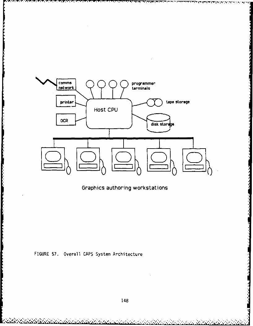
printertape storage
OCR disk stor *
Graphics authoring workstations
FIGURE 57. Overall CAPS System Architecture
148

The host must also be able to connect a number of asynchronous terminals forprogram editing and development. They will also be used for non-graphicsrelated editing or file access from remote sites, in a fully deployedconfiguration. A controller that can run a total of up to eight terminals (orserial printers) running at 9600 or 19.2 Kbaud is needed. There are manyavailable, such as from the manufacturer of the host CPU.
The particular choice of terminals used for this purpose is not verysensitive. One needs to have high assurance that the vendor is supplying asystem that is truly VT0 compatible, and that the terminals are capable offully working at 9600 or 19.2 Kbaud. Any such terminals can be used.
The disk and tape requirements are closely linked to the support requirementsof the manufacturer of the host CPU. The minimum amount of storage requiredhas been estimated by reviewing MTPs. They indicated a page count of about5,000 pages, each covered with approximately 50% figures and tables and theremainder being text. Given that we will need to keep online perhaps threedifferent versions or levels of the documents, and given internal storageinefficiencies, we estimate that between 50 to 100 megabytes of disk storageare needed for text alone.
The graphics requirement can be derived from the number of drawings needed fora prototypical MTP, and our conclusion regarding the storing of line drawings.An object oriented image description system is capable of presenting highquality images similar to the ones now in use. We are not considering goingto a photographic quality of illustration in this versionof the system. Anaverage MTP would require no more than about 500 nodes to describe. If eachnode is made up of an 8-tuple of 4-byte parameters, each such drawing wouldneed 16,000 bytes of storage. (Note that this imposes a lower limit on therecord size being managed by the relational database manager). We estimatethat about 2,500 drawings per MTP are needed; we do not see a requirement formany different generations of these drawings being online. This implies about50 megabytes of disk storage for drawings.
Together these total in the area of 100 to 150 megabytes of storage, based onthe assumption that the database manager can compact things quite well, andthere are no further duplications of redundant data. When combined with thespace needed for the operating system, software developed for CAPS, spoolingspace for print files, and other currently unspecified requirements, weconclude that 300 to 500 megabytes should be acquired.
To complement this disk storage system, we need a tape mechanism that isprimarily oriented toward making backups of the online data, and moreinfrequently used to recover data from offline, or to move data from site tosite in the future. To make practical backups, we require that the tapesystem be capable of backing up 500 Mbytes in about one hour. Hence the tapeshould write at last 10 Mbyte per minute, and each tape reel (or cartridge)must hold 100 Mbyte or more (to minimize the number of tape swaps).
149

Whether we require one disk drive or two, and one tape drive or two, isdetermined not by the operational requirements of the system, but rather bythe ability of the manufacturer to maintain and support a system that hasfailed, and to recover data. There is no stated requirement for CAPS to beable to run 24 hours per day, in a non-stop fashion. Hence we are assumingthat a vendor providing an 8 hour turnaround service policy, which can bemaintained with only one disk and one tape drive meet the objectives of thisprogram. Additional devices will add cost, and can actually be integratedinto the system quite easily if it should later be concluded this is animportant matter.
We are assuming that the primary output form will be hard copy masters readyfor duplication as standard ARTEPs. Over time this will evolve to fullyelectronic forms of distribution, but initially paper is required. Hence weneed a series of output devices that can handle the large number of objectoriented drawings, which occupy as much as 50% of each page. This needs to bea laser printer, and realistically we need to produce 1000 pages per day at apeak, hence at least 5 ppm.
The Xerox 2700 Model II does not have the graphics capability needed to handlethe task required. The Xerox 5700 does have the capability, and is alsocapable of higher speed use. The QMS 1200A version of the Xerox 2700 can dothe needed graphics, but will run at only 12 ppm or less for complex graphics.The most recent and economic of all the laser devices is the AppleLaserWriter. This device is especially attractive because the high levelgraphics language that it accepts is now available as the input language toseveral even higher quality phototypesetters. This means that we will be ableto direct the output to one of these typesetters, getting out film masters ofeven higher quality than a 300 lines per inch laser device can supply.
Another needed peripheral is an optical character reader, which will be usedprimarily for the purpose of loading the existing ARTEPs documents. This willlargely be a one-time job. We anticipate converting to electronic form ONCEand not doing this multiple times. Many of the relevant background referencedocuments are already in floppy disk word processing form, and we will be ableto bypass hard copy entirely for these documents. The prime criteria for theoptical character reading system is to be able to read a reasonable variety oftypewriter fonts, and not only an OCR produced font. It should support Elite,Pica, Courier, etc. The quality of the documents may not be in masterquality. Remarkably high comments have been noted on the ability of the DESTreader to handle documents that are far below its officially rated quality,hence capable of inputting almost any existing typed pages.) We wish to loadup the documents during a reasonable amount of time (once), and if we use theperiod of one week to set a scale, to load the approximate 5,000 pages we needloaded, we need a rate of 125 p/hr or more (approximately 100 char persecond). It does not seem worthwhile investing in faster units than this,since the load is primarily done at the front end, and the price for fasterunits goes up dramatically for higher speeds. Either the DEST Turbo 203 orthe Alphaword 80 Model C products appear to meet the criteria we haveestabl i shed.
150
[Work Stations. The main interface to the system will be through a highvisual graphic environment. Standard ASCII text terminals are simplyincapable of expressing the images and charts needed to manage the CAPS data,and to represent the quality of documents that the system is producing.
As well, to limit the speed requirements of the host processor, we haveelected to use high performance workstations, each with their own processor.This processor will run its own operating system (i.e., UNIX), which will beidentical to the host system, for data and task exchange, and maintenancepurposes. The machines must be capable of loading data via a host networkattachment at rates of 1 to 10 Mbits, since they do not have a large amount oflocal storage, and are requesting their data continually in a burst fashion
- from the CPU.
*. Three candidate machines have been evaluated from the graphics point of view,in terms of their monochrome resolution (that is to say, the number ofresolvable points on the display screen used for data).
They are:
Apple Macintosh 512 x 342 dotsAT&T UNIX PC 720 x 340 dotsApollo DN300 1024 x 800 dots
If we compare the total number of points on these three screens, we find thatthe Apple has about one fifth the number of the Apollo, and the AT&T about onethird. We judge the size and detail of the Macintosh scale screen marginallylow, and the UNIX and Apollo screens sufficiently detailed.
We also require that the workstations provide a standard supported pointingdevice, such as a mouse, and a network connection that can go to the hostsystem. All three of these systems provide these features, but to differentdegrees of performance.
From the point of view of the operating environment, the Macintosh does notrun UNIX in any kind of native mode. (As well, it does not have any standardoperating system other than Apple's unique one as an alternative. It cannotbe upgraded beyond 512K of memory, and the fastest standard output port runsat only 230 Kbits per second, far below for the other two.)
The AT&T UNIX PC has just been announced at the time of writing of thisconcept study. AT&T has introduced a 1 Mbit/second LAN (STARLan) for the UNIXPC. AT&T has also stated that there will be a connection to AT&T 3B machines,which are UNIX hosts normally running 3BNET, which is in fact Ethernet. Thedetails of a direct Ethernet interface for the UNIX PCs, or alternatively theavailability of a STARLan interface directly on a VAX 11/750, or equivalentgateway, need to be resolved prior to selection of this option forworkstations. The Apollo-based solution is committed by the vendor at thistime..
-, - - .. % % . . . .-. .-. - - . - . - % - - . . - .- .- . - . . -. - - . . . .. . - . -.. . - .* . *- .. - .. - -, .. .

Apollo on the other hand has an extremely impressive performance network thatconnects its Domain workstation. It it one of the highest performance andmost effective systems around, and well respected in the industry. However itis used only by Apollo, hence to connect into a host requires a gateway totranslate from Apollo's network to a more industry standard choice, such asEthernet. Given the fact that the Apollo configuration exists today, we haveindicated that it is the environment of choice.
Each of the workstations should have at least 1 Mbyte of RAM memory installed,with the capability of additional amounts as a future option. This is again amajor restriction on the Apple Macintosh, whereas 1 megabyte is quite standardfor the other two machines mentioned.
The UNIX offerings on the three machines under consideration (DEC VAX 11/750ULTRIX, Apollo DN300, and AT&T UNIX PC) are all derived from an AT&T licensedUNIX. Discussions with the vendors of Oracle and Ingres do not indicate anytechnical difficulties in supporting these configurations in a networkingmode. Both point out that at this time, due to the recent announcement dataof the AT&T UNIX PC, neither vendor has officially committed to support ofthis machine, but both are strongly leaning towards it.
152

ESTIMATE OF CAPS DEVELOPMENT EFFORT
In this section we describe our estimate of the R&D program that is implied bythe CAPS functional requirements and system design described in the previouschapters. We describe the program stages and tasks, the estimated person-months to perform the various tasks, and the cost of acquiring the hardwarefor two alternative system architectures. Finally, we provide a "strawman"model of a program plan that would meet the R&D program requirements.
Program Stages and Tasks
Obviously, a number of program plans could be devised that would ultimatelyproduce the CAPS system. The objective of the following program plan is notto constrain the R&D program to a specific program plan, but to describe theprimary activities and deliverables that are essential to the overall CAPSsystem development.
CAPS Development Stages. A CAPS R&D program would consist of a number ofprogram stages, during which a variety of tasks would be performed. Here wedescribe a program plan with six developmental stages, namely (1) front-endanalysis, (2) system design, (3) hardware acquisition & software coding, (4)unit testing, (5) system integration and testing, (6) system packaging anddocumentation. During the first stage, the technical team members, in closecoordination with the ultimate CAPS user(s), would conduct a front-endanalysis to develop the detailed system objectives and functionalspecifications for all system modules. The output of this stage would be adetailed Functional Specifications Document, which would be a primary contractdeliverable. This document would be subject to approval by the ContractingOfficer's Technical Representative (COTR), and would serve as the ultimate"contract with the customer" in providing detailed technical directions to theCAPS system developers.
The second stage of system development, the system design, would focus ondeveloping the detailed hardware and software designs. In the case of thesoftware design, the output would typically be in the form of. ProgrammingDesign Language (PDL) specifications of all program modules. The third stage,software coding would follow upon the approval, by the system developmentmanagers in consultation with the COTR, of the PDL specifications. Alsoduring this stage, the specific hardware for CAPS would be acquired, andinitial installation testing and acceptance would be performed.
The fourth stage, unit testing, would focus on evaluating and modifying asnecessary each module within the CAPS system software, as well as conductingthe initial steps of integrating various software modules together. Thisfourth step would include explicit demonstrations of individual modules,independent of other module functions that would be integrated later in thedevelopment program.
153

Following closely upon the fourth stage would be the fifth stage of systemintegration and test. This stage would probably be structured as an iterativeprocess, with more and more system functions being integrated on astep-by-step basis. The final output of this stage would be a demonstrationof all of the system functions for the entire CAPS development system.Concurrent with this integration stage, the loading of the ARTEP databasewould be conducted by the contractor personnel. Thus, the systemdemonstration at the end of this stage would include demonstrations of ARTEPmaterials production, based on the initial database that had been loaded.
The final stage of system development would focus on packaging the systemcomponents, both in terms of hardware and software, and on developing thesystem documentation. The documentation would include not only thedescriptions of the system components, but also all training documents thatwould be used to assist the users to become fully proficient and productivewith CAPS.
CAPS Development Tasks. A number of tasks, grouped into major task efforts,would be performed concurrently during the various development stages. All ofthese tasks are implied by the various system capabilities that have beendescribed in previous chapters. The first major effort is concerned withdeveloping the database management system that will be used in CAPS. Whereasa commercially-available relational DBMS (Oracle) has been specified for CAPS,several tasks must be performed to integrate this DBMS into CAPS and toprovide the ARTEP data. These tasks include (1) database definition (2)database loading, and (3) inter-networking.
The second major effort in CAPS will be to design, develop, and integrate thegraphics user interface. The tasks here include (4) interface development,(5) user guidance creation, (6) graphics tools development, (7) graphicscreation, and (8) consistency tools creation.
The third major effort will be to develop and integrate the ARTEP materialsproduction subsystems in CAPS. The tasks here include not only (9) authoringguides development, and (10) hard copy preparation system development, butalso (11) version control creation, which will allow the CAPS system to assistthe users in controlling the numerous versions to ARTEP materials that must beproduced.
The fourth major effort in CAPS development will be (12) subsystemsintegration, in which all of the system elements are merged into the overall,integrated CAPS system.
Estimated Manpower Requirements
Table 9 shows the estimated manpower, expressed in person-months, that will berequired to conduct the CAPS development tasks during the various programdevelopment stages. This estimate includes the efforts by all members of thetechnical development team, including program management.
154
-.- , .: . . .-. . . . -. . . . . . .. . -. . . . .*. . .. . . . . . ., . , _ . .- . .-

LA-A
co x 0
-- x r,
I-E
o A a- N 4 1 * N IC V
ai u.LAJ~~~~~~~d C11 CIS_____ ______ ___
.4 LIJ 06 t- 6 6 '-J Z
~ 155

o=Tt - T ' -.P- TV-% " T VqLF'-'
Hardware Procurement Cost Estimates
In this section we provide estimates of the procurement costs for the CAPShardware. These estimates are based on two proposed architectures: namely,(1) a system that uses Appollo workstations, and (2) an alternative systemthat uses AT&T UNIX PC workstations. The technical advantages anddisadvantages of these two alternatives were discussed previously.
The Apollo-based CAPS system is illustrated in Figure 58, and the associatedcosts are included in Table 10. The AT&T UNIX PC-based system is illustratedin Figure 59, and the associated costs for this alternative are included inTable 11.
Program Plan
Figure 60 shows the sequence of program tasks as they might be performedwithin a two-year system development program. Again, the tasks could beperformed according to a variety of program plans. The purpose here is toillustrate the relative order in which the tasks would probably be conducted,and to indicate the general time period in which the previously estimatedmanpower would be expended. This program plan assumes that the manpower is
evenly distributed across the various program stages.
156
............................................

printerstreamer
VAX 1 /750tape storage
R read
S456 MBdisk stor e
Ethernet LAN
gateway Use serve 500 MIB
total of 10 authoring workstations
FIGURE 58.APPOLLO WS-BASED CAPS ARCHITECTURE
157

TABLE 10COST ESTIMATE
Apollo-based CAPS Architecture
HARDWARE
Qty Manuf/Model Description Price (ea $K) TotalComputer1 DEC 750-XA-BE VAX 11/750, 2 MB RAM 60.0 60.0
ULTRIX incl.1 DEC MS750-CB 2 MB additional RAM 9.0 9.01 DEC DZ11-DP 8 port asycn controller 2.2 2.2I Interlan Ethernet interface 4.0 4.0
(or equiv.)Data Storage1 DEC RA81 456 MB disk storage 19.0 19.01 DEC TU80 1600 bpi, 100 ips 11.0 11.0
tape streamerCRT Terminals4 DEC VT100 or equivalent 1.9 7.6Printers2 Apple LaserWriter hard copy device 7.0 14.01 DEC LP32-EA 600 lpm bank printer 14.0 14.0
(or equiv.)1 DEC LA120-DA Console printer 2.8 2.810 Apple ImageWriter local printers on 0.5 5.0
each workstationOptical character reader1 DEST Turbo 203 or OCR reader 10.0 10.0
Alphaword 80 Model CGraphics Terminals10 Apollo DN300 graphics workstations, 10.0 100.0
1 MB RAM, 800 x 1024,Domain LAN
1 Apollo DFS-500M file server with 36.0 36.0500 MB storage
1 Apollo COM-ETH Ethernet gateway to VAX 3.5 3.5
SOFTWARE
Qty Manuf/Model Description Price (ea $K) Total
1 DEC QD821-HM ULTRIX distribution 2.5 2.510 Apollo UNIX UNIX license fee 0.3 3.01 Oracle DBMS VAX database license 48.0 48.0
TOTAL COST 348.6
158

printerstreamerVAX 1 /750tape storage
R Rread456 MB
_disk stq~ge
7 Ethe net LAN
00000C
total of 10 authoring workstations
FIGURE 59.AT&T UNIX PC-BASED CAPS ARCHITECTURE
159

WI jf 0.4 TT 17 .7 .7 A. X 77 7771-7Y:
TABLE 11COST ESTIMATE
AT&T UNIX PC-based CAPS Architecture
HARDWARE
Qty Manuf/Model Description Price (ea $K) Total
Computer1 DEC 750-XA-BE VAX 11/750, 2 MB RAM 60.0 60.0
ULTRIX incl.1 DEC MX750-CB 2 MB additional RAM 9.0 9.0I DEC DZ11-DP 8 port asycn controller 2.2 2.21 Interlan Ethernet interface 4.0 4.0
(or equiv.)Data Storage1 DEC RA81 456 MB disk storage 19.0 19.01 DEC TU80 1600 bpi, 100 ips 11.pO 11.0
tape streamerCRT Terminals4 DEC VTI0 or equivalent 1.9 7.6Printers2 Apple LaserWriter hard copy device 7.0 14.01 DEC LP32-EA 600 1pm band printer 14.0 14.0
(or equiv.)1 DEC LA120-DA Console printer 2.8 2.810 Apple Imagewriter local printers on 0.5 5.0
each workstationOptical character reader1 DEST Turbo 203 or OCR reader 10.0 10.0
Alphaword 80 Model CGraphics Terminals10 AT&T UNIX PC graphics workstations, 6.0 60.0
1 MB RAM, 720 x 340,20 MB local disk
10 AT&T or ? Ethernet interface 1.0 10.0(estimated)
SOFTWARE
Qty Manuf/Model Description Price (ea $K) Total
1 DEC QD821-HM ULTRIX distribution 2.5 2.51 Oracle DBMS VAX database license 48.0 48.0
TOTAL COST 279.1
160
.;*. . ~. *.. . *. . . .. . .. . . .. .. .. - .... ... *... .- .. . ... .. . .. . . . .::. :.,:l.

Year I Year 2
FIGURE 60.CAPS PROGRAM PLAN
161