computer organization (input-output) - prof. (dr.) k. r ...krchowdhary.com/co/12-co.pdf · to...
TRANSCRIPT

Computer Organization(Input-output)
KR ChowdharyProfessor & Head
Email: [email protected]
webpage: krchowdhary.com
Department of Computer Science and EngineeringMBM Engineering College, Jodhpur
November 14, 2013
KR Chowdhary Input-output 1/ 42

Introduction to IO
◮ IO of computer makes itpossible to have interactionwith the outside world. IO arethe devices outside the CPUand memory, to whichCPU/memory communicate toget theinformation/data/programsinto computer as well as sendthese outside.
◮ IO devices are: Keyboard,mouse, monitor(computerdisplay), hard-disk, CD ROM,pendrive, printer, networkcard, etc.
◮ Due to the large variation inspeed, IO devices cannot beconnected to the bus directly.
Typical speeds are: keyboard:5-10 char per sec., printer100s - 1000s char per sec.,hard disk: millions of char(bytes per sec.), etc. If CPU isdesigned to interact withdevices directly through thebus, its complexity increasesexcessively.
◮ Different IO devices store thedata in different formats.Consequently, they areconnected to the bus via IOcontrollers (called IOmodules).
◮ One side of these controllers isconnected to to the bus andother to device.
KR Chowdhary Input-output 2/ 42

Synchronous and Asynchronous I/O
◮ Asynchronous(non-blocking)I/O: is a form of I/Oprocessing that permits otherprocessing to continue beforethe transmission has finished.
◮ I/O operations on a computercan be extremely slowcompared to the processing ofdata. An I/O device canincorporate mechanical devicesthat must physically move,such as a hard drive seeking atrack to read or write; this isoften far slower than theswitching of electric current.For example, during a diskoperation that takes ten
milliseconds to read/write, aprocessor that is clocked at 1GHz could have performed tenmillion instruction-processingcycles. (These approach areeither polled or interruptdriven)
◮ A simpler approach to I/Owould be to start the IO andthen wait for it to complete,called (synchronous orblocking I/O), would blockthe execution of instructionswhile the communication(data transfer) is in progress,leaving system resources idle(For example inDMA)
KR Chowdhary Input-output 3/ 42

Asynchronous data transfer
If registers in the interface share common clock with CPU register, thentraffic between the two is synchronous.
◮ Asynchronous data transfer takesplace between two independentunits.
◮ One way of achieving this is bymeans of strobe pulse to indicatethe intention of data transfer.
◮ In below, CPU is data sourceand initiator of strobe.
Source
unit
Destination
unit
data bus
strobe
data validdata
strobe
Figure 1: Timing diagram(TD)for memory write (sourceinitiated strobe)
Source
unit
Destination
unit
data bus
strobe
data validdata
strobe
Figure 2: TD for memory read(destination initiated strobe)
◮ In above CPU (data destination)initiates strobe, & memoryreleases data.
◮ In both cases, source unit has noway to know that destination hasreceived the data, anddestination has no way to knowthat source has sent the data.
KR Chowdhary Input-output 4/ 42
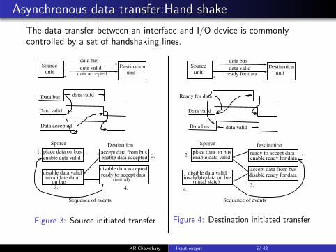
Asynchronous data transfer:Hand shake
The data transfer between an interface and I/O device is commonlycontrolled by a set of handshaking lines.
Source
unitDestination
unit
data bus
data accepted
data validData bus
data valid
Data accepted
Data valid
Sporce Destination
place data on busenable data valid
accept data from busenable data accepted
disable data acceptedready to accept datadisable data valid
inivalidate dataon bus (initial)
Sequence of events
1.2.
3. 4.
Figure 3: Source initiated transfer
Source
unitDestination
unit
data bus
ready for data
data valid
Ready for data
data valid
Data bus
Data valid
Sporce Destination
Sequence of events
ready to accept dataenable ready for data
accept data from busdisable ready for data
place data on busenable data valid
disable data validinvalidate data on bus
(inital state)
1.2.
3.4.
Figure 4: Destination initiated transfer
KR Chowdhary Input-output 5/ 42

Hand shaking
◮ Hand shaking scheme providesa high degree of flexibility andreliability (the successful datatransfer relies on the activeparticipation of both parties)
◮ If one unit is faulty, datatransfer cannot be initiatedand completed. Such error canbe detected by time outmechanism.
KR Chowdhary Input-output 6/ 42

I/O Controllers
◮ Devices are connected to the bus through I/O controller (I/OModule).
System Bus
CPU memory I/O
Controller
To peripheral devices(tape, Hard disk, CD)
Figure 5: Connection of I/O devices and I/O controller
KR Chowdhary Input-output 7/ 42

I/O controllers functional units
Dev
iceIn
terfaceD
evice
Interface
Lo
gic
Lo
gic
Data
register
Statu
s/ctrlreg
ister
I/OLogic
data bus
address bus
control bus
To system busTo device
data
status
control
data
status
control
bbb
Figure 6: I/O device Interface
◮ Functions performed I/O controller are:1. Control and timing of data read/write2. Communication with processor and devices3. Data buffering (to handle speed mismatch)4. Error detection
KR Chowdhary Input-output 8/ 42

Typical I/O Interface unit
To deviceTo CPU
Port ARegister
Port BRegister
ControlRegister
StatusRegister
Bidirectional
data busBus
buffers
Tu
nin
gan
dC
on
trol
CS
RS1RS0
RD
WR
Inte
rnal
bu
s
Chip select
Register-
select
I/O read
I/O write
Figure 7: IO device Interface
CS RS1 RS0 Register selected0 x x None: data bus in high impedance1 0 0 Port A register1 0 1 Port B register1 1 0 Control register1 1 1 Status register
KR Chowdhary Input-output 9/ 42

Detailed functions of I/O controller
◮ Control and timing of dataR/W: Coordinate the flow oftraffic between internalresources and external devices.
1. The processor interrogatesthe I/O controller to checkthe status of the attacheddevice.
2. The I/O controller returnsthe device status.
3. If device is ready totransmit, processor requeststransfer of data by meansof a command to I/Ocontroller.
4. I/O controller obtains a unitof data (e.g., 8 or 16 bits)from the external device.
5. The data are transferredfrom I/O controller to theprocessor.
◮ Processor communicationinvolves:
1. Command decoding: I/Ocontroller (for disk) acceptscommands from processor:READ SECTOR, WRITESECTOR, SEEK tracknumber, etc.
2. Data are exchangedbetween processor and I/Ocontroller
3. Status reporting: BUSYand READY.
4. Address recognition: I/Ocontroller must recognizeaddress of each peripheral.
KR Chowdhary Input-output 10/ 42

Detailed Functions of I/O controller...
◮ Data buffering: (handles speedmismatch) Buffering makespossible the communication atthe speed of CPU/ memory/device.
◮ I/O controller responsible forerror detection and reportingto processor: paper jam, baddisk track, changes to the bit
pattern (parity check)
◮ IO Channel/Processor: AnI/O controller taking most ofthe detailed processingburden, presenting a high-levelinterface to the processor, andused on mainframes.
◮ I/O Operations: Control, test,read, write.
KR Chowdhary Input-output 11/ 42

Device interface
Control logic
To IO controller
Control Data
Buffer
Transducer
Data to and
Device
signalStatussignal
from environment
Figure 8: I/O device with Interfaces
◮ The control provide communication between controller and device
◮ Environment is magnetic surface in the case of hard disk, opticalsurface in case of CD-ROM.
KR Chowdhary Input-output 12/ 42

Types of I/O (or Modes of Transfer)
◮ Polled I/O (or programmed I/O)
The cpu polls the device continuously after some interval, whetherthe device wants to transfer the data. If yes, the cpu transfer a byteto or receives a byte from it.
Read the byte
arethere morebytes to be
read?
yes
next step ofprogram
Read status bit
deviceready?
no
yes
short wait
yes
Figure 9: Read operation from device in polled I/O.
KR Chowdhary Input-output 13/ 42

Polled I/O write operation
read status bit
deviceready ?
Noyes
write the byte
morebytes towrite?
no
next stepyes
wait
Figure 10: Write operation from device in polled I/O.
◮ CPU reads the status bit, if it is set(indicating that device is ready),the byte is written by cpu to I/O, else it waits for some time andagain tries.
◮ Is it efficient method?
KR Chowdhary Input-output 14/ 42

Polled I/O: Memory-mapped v/s Isolated I/O
Figure 11: Memory-mapped and Isolated I/O.
KR Chowdhary Input-output 15/ 42

Polled I/O: for 8085
◮ Repeatedly tests the status of I/O device, hence it wastes the cputime. However, its architecture is simple to implement.
Example: busy waiting then input
wait: IN 1 ; read io device status
CPI ready ; if ready, set Z=1, else set z=0
JNZ wait ; io device waiting
IN 2 ; read data into accumulator
;Transfer a block in 8085
LXI H, 10
MVI B, 100
loop: IN 7 ; read from port 7
MOV M, A
INX H
DCR B
JNZ loop
KR Chowdhary Input-output 16/ 42

Memory Mapped v/s Isolated I/O
◮ I/O devices are connectedthrough I/O module or I/Ocontroller to bus.
◮ Each I/O port of the modulehas an address. If that isaddress of device, it is IsolatedI/O. Alternatively, addressspace of I/O can be treated asmemory locations. Thus,address space of memory getsreduced by the magnitude I/Oaddress. This is Memorymapped I/O.
◮ In isolated I/O only IN addr/OUT addr instructions exist.
For 8-bit I/O address total 256I/O addresses exists in 8085.
◮ In memory mapped IO all thememory reference instructioncan be executed for IO ports:STA addr, LDA addr, MOV A,
M; MOV B, M; MOV M, C;
ADD M; ADI M; ORA M; ORI
M; SUB M; SBI M (8085processor). Hence, memorymapped IO is more flexible touse compared to Isolated IO.Now, at least in theory, entirememory can space can beused as IO address space.
KR Chowdhary Input-output 17/ 42

Interrupts driven I/O
Interrupt driven I/O◮ The program controlled I/O
degrades the systemperformance as the cpu getstied down to the I/O.
◮ The interrupt mechanismgreatly improves theperformance of the CPU.
◮ In interrupt driven IO, timingof I/O is controlled by thedevice, and the cpu remainsoccupied in its own job forrest of the time.
◮ IO device interrupts the CPUwhen IO is required. On thisCPU saves its status includingthe PC, and control istransferred to an ISR
(interrupt service routine),which performs I/O. On returnfrom ISR, CPU resumes at itsprevious operation.
◮ CPU gets an interrupt when,for example,
- a character is entered onkeyboard,
- monitor is ready for nextrefresh
- a block transfer complete frommemory to I/O or I/O tomemory
- HW interrupts are due todivision by zero, or an attemptto execute a privilegedinstruction by user program.
KR Chowdhary Input-output 18/ 42

Classes of Interrupts
Classes of Interrupts:1. Program: Generated by some
conditions which occurs as aresult of instruction execution:
◮ arithmetic over flow◮ divide by zero◮ attempt to execute illegalmachine instruction
◮ reference to outside user’sallowed memory space
2. Timer Interrupt: generated bytimer of processor; allows toperform certain functions atregular intervals
3. IO: Interrupt generated by IOcontroller to: signal normal
completion/start of an IO, orto send variety of errorconditions
4. HW failure: Power failure,memory parity error.
Advantages of Interrupts
◮ Improves processing efficiencydue to slow IO and fast CPU
◮ User program does not needany special code for interrupt
◮ Processor and OS areresponsible to suspend theprogram, and cause it toreturn back
KR Chowdhary Input-output 19/ 42

Interrupt Processing
User Program
write
write
IO Program
IO Command
End
End
1
2
3
4
5
I/O = 4 + 5 (A)
◮ User program waits till theinterrupt is processed andcontrol returns back to it.
◮ 4 = save context, 5 Interrupthandler + context restore.
◮ (A): Control returns backimmediately to user program
User Program
write
IO Program
IO Command
End
1
2
3
4
I/O = 4 + 5
Interrupts handler
End
Interrupt5
(B)
◮ (B): user program is called onthe completion of processingof interrupt handler.
◮ What is difference betweentwo?
KR Chowdhary Input-output 20/ 42

Handling Multiple Interrupts
◮ Program may be receiving data from communication line, and sendthem to printer. So communication line will cause interrupt, as wellas the printer.
◮ Two approaches to handle multiple interrupts: 1) Disable interrupts,2) Priority interrupts
user program
Intr 1
Intr2
Int serv. routine1
Intr. service routine 2
Serquential Interrupts
Intr1Intr2
user program
Nested Interrupts
I1: Printer int, I2: communication
serv. Int, I3: Disk intr
I1
I2
I3
KR Chowdhary Input-output 21/ 42

Working of Interrupt
◮ Interrupt request pending, if any, is tested by cpu after execution ofevery instruction. If pending, it is serviced and cpu resumes normalexecution, else cpu continue with the next instruction.
fetch instruction
execute instruction
isinterrupt pending?
yes
save pc, service interruptretrieve pc
no
Figure 12: Interrupt servicing
KR Chowdhary Input-output 22/ 42

Working of interrupt...
◮ Steps:
1. CPU identifies the source of interrupt (may require polling of I/Odevice)
2. CPU obtains address of ISR. (may be supplied by device along withInterrupt request)
3. PC, CPU status saved4. PC loaded with ISR address
◮ Usually, the ISR has DI instruction at its beginning and EI (Enableintr.) at its end, followed by return
ISR: DI
high priority ISR
EI
RET
◮ Interrupt selection/Device Identification:
1. Multiple interrupt lines (limits interrupts)
2. Software polling (test I/O, read adr register): time consuming
3. Vectored Interrupt (daisy chaining/HW polling:)
KR Chowdhary Input-output 23/ 42

Working of interrupt
1. Multi-line interrupt:-Called multi-level interrupt. Noneed of HW or SW to scan ports.- Unless some other technique isused, CPU may have to executethe program that fetches the ISRaddress. Can be eliminated byvectoring technique. (fixed priority)
IO port 0 IO port 1 IO port k
CPU
Interruptregister
Intr req lines
To IO devices
b b b
Figure 13: Multi-line interrupts
2. Single-line interrupt system:All the interrupts are ORedtogether. An interrupt from anydevice will set the interrupt flag inCPU. On knowing that, CPUdetermines source of interrupt.(programmable priority?)
bb
To IO devices
Io port 0 IO port 1 IO port k
Interrupt request
CPU
Interrupt
FF
b b b
Figure 14: Single-line interrupt
KR Chowdhary Input-output 24/ 42

SW poll and interrupt vectoring
◮ Software poll: On detecting interrupt, the processor branches to aservice routine, which polls IO modules to determine who hasinterrupted, and then serves ISR of that.
- Disadv: time wasted in polling.◮ Daisy Chaining:
1. Hardware polled. All IO modules share a common interrupt line andInt. ack.like is daisy chained through these modules.
2. Requesting module places a word on the data bus (address of IOmodule - called vector)
3. Vector is used a pointer to ISR (called vectored interrupt)
Busterminator
Bus
terminator
BPRN BPRN BPRNBPRO BPRO BPRO(highest priority) (lowest priority)
Master 1 Master 2Master 3
Distributed ArbitrationBPRN: Bus priority out
BPRN: Bus priority inIntrrupt line
Interruptack. line
Figure 15: Vectored interrupt
KR Chowdhary Input-output 25/ 42

Vectored Interrupt
◮ The device sets INT=1 whenit wants to cause the interrupt
◮ Interrupt vector: An 8-bitsignal for device to identifyitself, which is used as anentry into a interrupt vectortable to get the startingaddress of the ISR (Interruptservice routine).
device A
device K
bbb
Interrupt
controllerCPU
INT
INTvector
b
Figure 16: Vectored interrupt
◮ Most flexible and fastestresponse to interrupt is therewhen interrupt request causesdirect HW implementedtransition to current interrupthandling program.
◮ This requires that interruptingdevice supply to cpu thestaring address or transfervector of that program. Thetechnique is called vectoring.
KR Chowdhary Input-output 26/ 42

Vectored Interrupt contd.
◮ In the figure shown below, the interrupt vector is supplied by thedevice itself via the data bus
◮ Each I/O port may request the services of many different programs.
◮ Address on data bus modifies PC. Takes control of data bustemporarily. Alternatively send instruction call x
b b b
INT req 0
int ack0
int ack n-1
int req n-1
IO port 0 io port n-1
To IO devices
b b b
bbdata bus
To cpu
prio
ritycircu
it
(interrupt program address)
Int. req.
Intr. ack
Figure 17: Another implementation of vectored interrupt
KR Chowdhary Input-output 27/ 42

Vectored Interrupt with masking
◮ The k masked interrupt signals are fed into a priority encoder thatproduces a ⌈log2 k⌉-bit address, which is then inserted into programcounter as a sub-field.
Intrreq.
lines
interruptmaskregister
Interrupt pending
prio
rityen
cod
er
b
address to PC
Interrupt register
b
b
Figure 18: Intr. vectoring with masking of interrupts.
KR Chowdhary Input-output 28/ 42
Vectored Interrupt ...
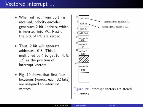
◮ When int req. from port i isreceived, priority encodergenerates 2-bit address, whichis inserted into PC. Rest ofthe bits of PC are zeroed.
◮ Thus, 2 bit will generateaddresses: 0-3. This ismultiplied by 4 to get (0, 4, 8,12) as the position ofinterrupt vectors.
◮ Fig. 19 shows that first fourlocations (words, each 32 bits)are assigned to interruptvectors.
0addr 16
4addr 28
8 addr 40
12 addr 200
16
28
40
200
device AISR
device BISR
device CISR
device D
ISR
vector addr of device A ISR
vector addr of device B ISR
Figure 19: Interrupt vectors are storedin memory
KR Chowdhary Input-output 29/ 42

IO controller
A
C lower
C upper
B
databuffers
8-bitinternal bus
controllogic
88
8
8
4
4
8
c̄sreset
A0
A1RD
WR
data
bus
To CPU
To IO device
Data
Bu
fferC
on
trol
Reg
ister
Figure 20: IO controller (intel 8255)/PPI-programmable peripheralInterface.
◮ The Intel 8255 is called IOcontroller/IO module. Thereare three IO ports: A, B, C.
◮ The port C can be used as two4-bit ports or one 8-bit ports.A, B are always 8-bit ports.All these ports can beprogrammed as Input, output,bidirectional in polled mode oras interrupt mode.
◮ Programming is done bywriting a 8-bit control word atport address 112. In polledmode certain lines can be usedfor handshaking.
KR Chowdhary Input-output 30/ 42

IO controller-8255
◮ Following tables show the direction of ports:
A0 A1 RD WR CS Direction0 0 0 1 0 A→ databus
0 1 0 1 0 B → databus
1 0 0 1 0 C → databus
0 0 1 0 0 databus → A
0 1 1 0 0 databus → B
1 0 1 0 0 databus → C
1 1 1 0 0 databus → control
◮ Three are 3-modes of operation for PPI 8255:
mode 0: Basic input/output, mode 1: strobed I/O; mode 2:bidirectional bus
◮ various bits of control word:
D7 = 1⇒ mode set flag, 1=active.
D6D5 = 00⇒mode 0,01⇒mode 1,1x ⇒mode 2
D4 = 1⇒ port A I/P, 0: O/P,
D3 for port C upper, D2 for mode 0 & 1, D1 for port B, D0 for portC lower. Any bit can be set or reset.
KR Chowdhary Input-output 31/ 42

Interrupt Controller
bb
b
C
A
B
8
8
Intel
82
55
PP
Ias
interru
pt
con
troller
data
data ready
data acknow-
data bus
A0A1
Readwrite
to IOdeviceto cpu
Intr request
ledgement
Figure 21: Programmable peripheralInterface as Interrupt Controller.
◮ 8255 chip is used as interruptcontroller. The port C is usedas interrupt port for strobing.Port A is used as data port fordata input or output.
◮ Interrupt signal is stored incpu register which isperiodically tested by the cpu.Usually, the interrupts areassigned priorities based onthe priorities of IO devices orservices they are performing.
KR Chowdhary Input-output 32/ 42

Introduction to DMA
DMA(Direct Memory Access)◮ CPU relinquishes the bus, and
get itself isolated. The IOtakes place between memoryand IO device at clock speed.When I/O is complete, DMAcontroller removes the busrequest line, CPU takes overthe bus, and processingresumes at the point is wasleft.
◮ IO transfers are limited by thespeed by which the CPU can
test and service IO.
◮ The testing IO status andexecuting IO commands canbe better used for processingtasks.
◮ DMA request by IO device isfor demand of BUS and notCPU (in interrupt it isreverse).
◮ The DMA request can begranted BUS at the end of anyCPU Cycles(fig.)
KR Chowdhary Input-output 33/ 42

Introduction to DMA
◮ DMA v/s Interrupts:- DMA break points are aftereach of following to opcodefetch, decode opcode, fetchoperand (if any), executeinstruction. However, theinterrupt break point is afterinstruction is executed, andnot in between.
◮ Why there is difference inbreak points of these?
Instruction cycle
DMA breakpointsFetch
instruction
CPUcycle
Interrupt breakpoint
Figure 22: DMA and Instructionbreakpoints during an instructioncycle.
KR Chowdhary Input-output 34/ 42

Functional blocks of DMA
main memory
Controlunit
AR ACC
IR ctrlunit
DMA req
DMA ack
To IO device
system bus
DMA controller
DC IO AR IO DR
address
data
control
CPU
Figure 23: DMA controller block diagram.
◮ Functional blocks: DC (data count) keeps initial count of no. ofwords /bytes to be transferred, IOAR: is memory address from thatlocation onward data is to be transferred to/from memory, IODR: IOdata reg., for holding word/byte while it is being transferred toIO/RAM.
KR Chowdhary Input-output 35/ 42

Working of DMA
◮ DMA is used for bulk data transfer between memory and IO.
◮ The cpu relinquishes the control of the bus, and surrenders it toDMA for doing this data transfer
◮ The transfer is initiated by CPU, and DMA controller interrupts thecpu to indicate that DMA is over
◮ DMA steps:
1. CPU executes two IO instructions which loads IOAR and DC. (IOARis base addr of main memory, DC = words count to be transferred)
2. DMA controller gives bus request when ready to transfer to data.On this DMA acknowledges (grants the bus to DMA controller) (buspriority control is used when request are too many)
3. DMA controller transfers the data.4. If IO device is not ready but DC > 0, the DMA controller deactivates
the DMA request. On this CPU acknowledges bus grant low, andresumes normal operation.
KR Chowdhary Input-output 36/ 42

Classification of DMAs
◮ DMA types:
1. Block transfer DMA2. Cycle stealing DMA (bus cycles are stolen by DMA, during the time
cpu is inactive, to carry out DMA)
◮ DMA block Transfer:
- Data of arbitrary length are transferred in a single continuous burst.
- DMA controller is bus master
- It is used when secondary memory devices are mag. disk, and cannotbe stopped or slowed down without loss of data.
- Supports maximum transfer rate
- CPU has to remain inactive for long period
◮ Cycle stealing DMA:
- allows DMA controller to use system bus to transfer one or severalwords/bytes, and returns control back to CPU
- long strings are split
- reduces the DMA speed but also the interference of DMA to CPU
KR Chowdhary Input-output 37/ 42

Exercises
1. Indicate whether the following constitutes a control, status, or datatransfer commands:1.1 Skip next instruction if flag is set1.2 seek a given record from a magnetic disk1.3 check if IO device is ready1.4 Move printer paper to beginning of next page1.5 Read interface status register
2. Why does the DMA has priority over CPU when both request amemory transfer?
3. How many 8-bit characters can be transmitted per second over a9600 baud serial communication link using asynchronous mode oftransmission with one start bit, eight data bits, two stop bits, andone parity bit?(a) 600 (b) 800 (c) 876 (d) 1200
4. A DMA module is transferring characters to memory using cyclestealing, from the device transmitting at 14400 bps. The processoris fetching instructions at the rate of 1 million instructions perseconds (1 MIPS). By how much will the processor be slowed downdue to due to the DMA activity?
KR Chowdhary Input-output 38/ 42

Exercises
5. Consider the system in which bus cycles takes 500 nsec. Transfer ofbus control in either direction from processor to I/O device orvice-versa, takes 250 nsec. One of the I/O devices has a datatransfer rate of 75 KB/s and employs DMA. Data are transferredone byte at a time.
5.1 Suppose we employ DMA in a burst mode. That is, the DMAinterface gains bus mastership prior to the start of a block transferand maintains control of the bus until the whole block is transferred.How long would the device tie up the bus when transferred a blockof 256 bytes?
5.2 Repeat the above for cycle stealing mode.
6. An asynchronous link between two computers uses the start-stopscheme, with one start bit and one stop bit, and transmission rate of38.8 kilobits per sec. What is the effective transmission rate as seenby the two computers?
KR Chowdhary Input-output 39/ 42

Exercises
7. A DMA controller serves four receive only telecommunications links(one DMA per channel) having speed of 64 kbps each.
7.1 Would you operate the controller in burst-mode or cycle stealingmode?
7.2 What priority scheme would you employ for service of the DMAchannel?
8. A processor and I/O device D are connected to main memory M viaa shared bus having width of one word. CPU can execute 106
instructions per sec. An average instruction requires five machinecycles, three of which use the memory bus. A memory read or writeoperation uses one machine cycle. Suppose that processor iscontinuously executing background program that requires 95% of itsinstruction execution rate but not any I/O instructions. Assume thatone processor cycle equals one bus cycle. Now suppose that the I/Odevice is to be used to transfer very large blocks data between M
and D.
8.1 If programmed I/O is used and each one-word I/O transfer requiresthe processor to execute two instructions, estimate the maximumI/O data-transfer rate, in words per sec., possible through D.
8.2 Estimate the same rate if DMA is used.
KR Chowdhary Input-output 40/ 42

Exercises
9. A typical CPU allows mots interrupts to be enabled and disabledunder software control. In contrast, so cpu provides facilitates todisable DMA request signals. Explain why it is so?
KR Chowdhary Input-output 41/ 42

Bibliography
John P. Hayes, ”Computer Architecture and Organization”, 2ndEdition, McGraw-Hill, 1988.
William Stalling, ”Computer Organization and Architecture”, 8thEdition, Pearson, 2010.
M. Morris Mano, “Computer System Architecture-3rd Edition”,Pearson, 2006 (chapter 11).
http://krchowdhary.com/co/co.html
KR Chowdhary Input-output 42/ 42