computer modeling of radiation and combustion in …/67531/metadc733463/m2/1/high...computer...
TRANSCRIPT
Computer Modeling of Radiation and Combustion in a Rotary Solid-Waste Incinerator*
cr5 w E d 8
F. C. Chang Energy Technology Division Argonne National Laboratory
9700 S. Cass Avenue Argonne, IL 60439
and
C. A. Rhodes Department of Mechanical Engineering
University of South Carolina Columbia, SC 29208
Submitted to 1995 ASME/JSME Pressure Vessels and Piping Conference, Honolulu, Hawaii, July 23-27, 1995.
* This work was supported by the U.S. Dept. of Energy under Contract W-31-109-Eng-38.
DISCLAIMER
Portions of this document may be illegible in electronic image products. Images are produced from the best available original document .
COMPUTER MODELING OF RADIATION AND COMBUSTION IN A ROTARY SOLID-WASTE INCINERATOR
F. C. Chang Energy Technology Division Argonne National Laboratory
9700 S. Cass Avenue Argonne, IL 60439
C. A. Rhodes Department of Mechanical Engineering
University of South Carolina Columbia, SC 29208
ABSTRACT
A mathematical model was developed to study the effect of the various particulates that occur in pulverized-coal flames of solid-waste incinerators. Radiation heat transfer between refractory surface and flame, transient conditions in the refractory, and chemical reactions in the waste material is included in the model. Radiation heat exchange is determined by the absorption factor technique. A first-order-chemical-reaction rate is assumed for the solid waste.
This study takes into account the radiation emission, absorption, and scattering of gaseous media for water vapor and carbon dioxide contained in the combustion gases. Soot particles are also investigated. The variables are mass fraction, particle size, complex refractive index, and amount of solid waste. Rayleigh scattering is assumed for particles.
Refractory-wall temperature variations, surface temperature of the refractory, solid-waste temperature, and solid-waste flow rates was investigated. This study is important for design purposes in determining the length of the incinerator required to completely burn the wastes.
INTRODUCTION
There is a continuing pressure for utility and industrial users of pulverized-coal-fired furnaces to use coal in burning waste. Decreases in either furnace efficiency or combustion efficiency are typically observed and the reasons for this are sought. In addition to differences in the combustion rate of individual coal particles, differences in heat transfer processes are expected. Because thermal
radiation is the principal mode of heat transfer to the walls in large furnaces, differences in radiative transport properties may be significant reasons for the observed efficiency decreases.
It is generally agreed that transfer of energy by infrared radiation from the flame to the walls is a key process in utility furnaces or incinerators that burn pulverized coal. The radiative transfer is due to both band emission from C02 and H20 and continuous emission from various types of particles. Because the radiation characteristics of the entrained particles can be expected to be related to coal type and particle size, changes in radiative heat transfer are a possible cause of the observed sensitivity of furnacehncinerator performance.
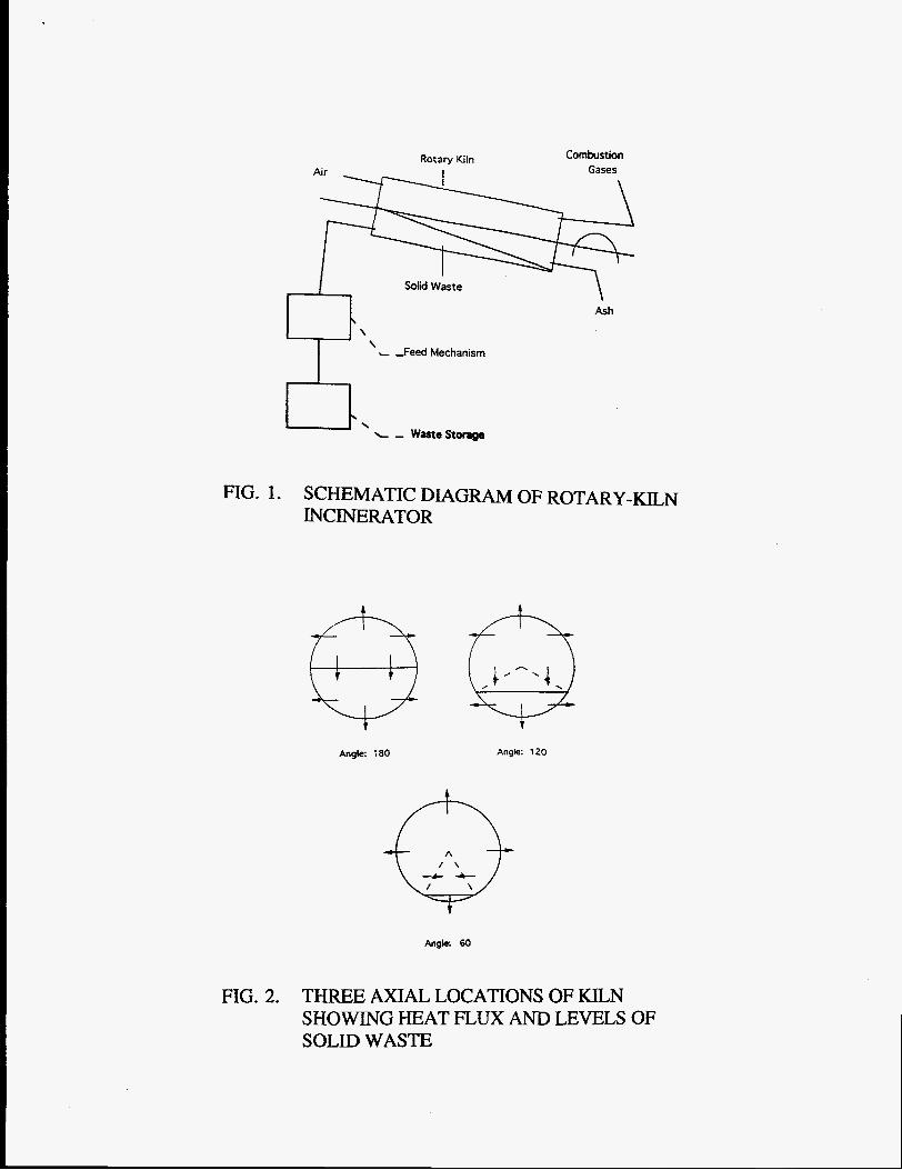
A rotary-kiln incinerator is a refractory-lined cylindrical shell mounted at a slight angle to the horizontal, as shown in Figure 1. The kiln is rotated about its longitudinal axis and the solid waste is fed into the upper end of the cylinder. Waste combustion occurs as the material moves to the lower end of the cylinder where ash is discharged. The gas flow may be in the direction of the waste flow. Speed of rotation may be used to control the residence time of the waste and to mix the waste with the combustion gas. Residence times vary from a few seconds for highly combustible waste to a few hours for less-combustible solid waste.
Absorption and the scattering coefficients of particles depend on the optical properties (that is the complex refractive index c = n - ik) of the particles, size of the particles relative to the wavelength of the incident radiation, and particle geometry. To avoid the complicated relationships of particle geometries in this study, the properties of particles have been simplified as follows:
Scattering particles are considered as spheres for broad geometric applicability. Scattering particles are considerably smaller than the wavelength of the incident radiation so that the scattering of particles is considered isotropic. Particles are considered dielectrics. Hence, the reflectivity of particle surface will be very small so that the absorption and the scattering of the particle surface will become significant.
The absorption spectrum of C02 is composed of bands positioned approximately at wavelengths 1.9, 2.7,4.3, and 15.0 pm [l]. The absorption spectrum for H20 is composed of four principal vibration-rotation bands (1.38, 1.87, 2.7, 6.3 pm), in addition to a pure rotation band [2]. Although other radiating gases, such as CO, NO, and S02, are present in the incinerator, they are usually neglected because of uncertainty about their spatial distributions and concentrations.
To focus on the direct effect of the main parameters, gas temperature and particle density are assumed to be uniform axially, radially, and circumferentially. The kiln wall is assumed to be gray and diffusely reflecting with a specified emissivity and temperature distribution. Absorption and
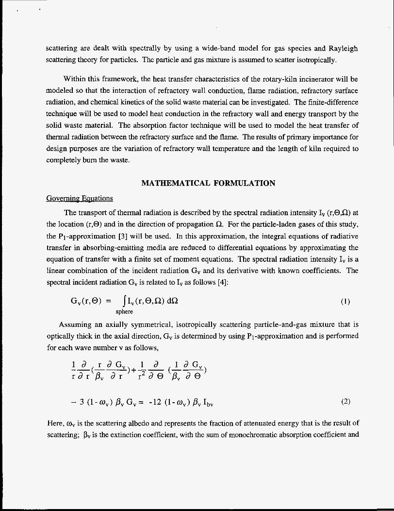
scattering are dealt with spectrally by using a wide-band model for gas species and Rayleigh scattering theory for particles. The particle and gas mixture is assumed to scatter isotropically.
Within this framework, the heat transfer characteristics of the rotary-kiln incinerator will be modeled so that the interaction of refractory wall conduction, flame radiation, refractory surface radiation, and chemical kinetics of the solid waste material can be investigated. The finite-difference technique will be used to model heat conduction in the refractory wall and energy transport by the solid waste material. The absorption factor technique will be used to model the heat transfer of thermal radiation between the refractory surface and the flame. The results of primary importance for design purposes are the variation of refractory wall temperature and the length of kiln required to completely burn the waste.
MATHEMATICAL FORMULATION
Governing; Eauations
The transport of thermal radiation is described by the spectral radiation intensity Iv (r,@,a) at the location (r,@) and in the direction of propagation $2. For the particle-laden gases of this study, the PI-approximation [3] will be used. In this approximation, the integral equations of radiative transfer in absorbing-emitting media are reduced to differential equations by approximating the equation of transfer with a finite set of moment equations. The spectral radiation intensity I, is a linear combination of the incident radiation G, and its derivative with known coefficients. The spectral incident radiation G, is related to Iv as follows [4]:
G,(r,@) = jIv(r,@,S1) dS1 sphere
Assuming an axially symmetrical, isotropically scattering particle-and-gas mixture that is optically thick in the axial direction, Gv is deterrnined by using Pi-approximation and is performed for each wave number v as follows,
1 d l d G , r a r pv d r r 2 d @ pv d o )+-- (--) --(-- i d r a ~ ,
Here, w, is the scattering albedo and represents the fraction of attenuated energy that is the result of scattering; pv is the extinction coefficient, with the sum of monochromatic absorption coefficient and
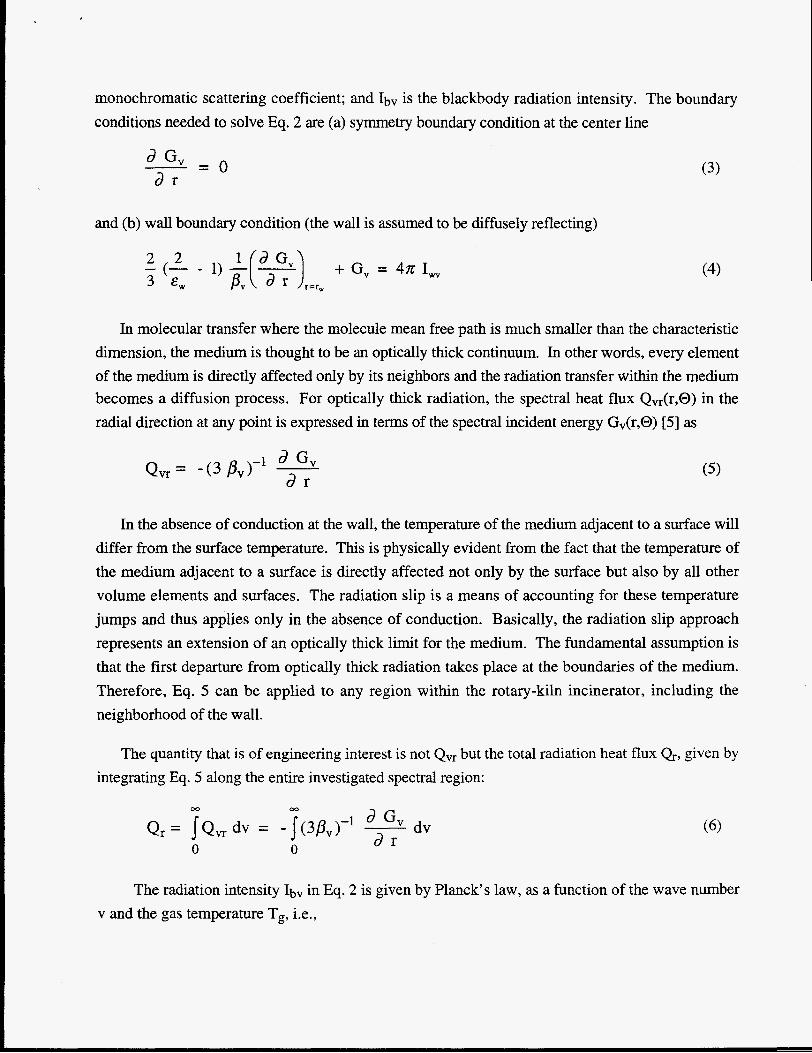
monochromatic scattering coefficient; and Ibv is the blackbody radiation intensity. The boundary conditions needed to solve Eq. 2 are (a) symmetry boundary condition at the center line
2- - 0 d G d r
and (b) wall boundary condition (the wall is assumed to be diffusely reflecting)
+ G, = 4~ I,
(3)
(4)
In molecular transfer where the molecule mean free path is much smaller than the characteristic dimension, the medium is thought to be an optically thick continuum. In other words, every element of the medium is directly affected only by its neighbors and the radiation transfer within the medium becomes a diffusion process. For optically thick radiation, the spectral heat flux Qvr(r,@) in the radial direction at any point is expressed in terms of the spectral incident energy Gv(r,@) [5] as
In the absence of conduction at the wall, the temperature of the medium adjacent to a surface will differ from the surface temperature. This is physically evident from the fact that the temperature of the medium adjacent to a surface is directly affected not only by the surface but also by all other volume elements and surfaces. The radiation slip is a means of accounting for these temperature jumps and thus applies only in the absence of conduction. Basically, the radiation slip approach represents an extension of an optically thick limit for the medium. The fundamental assumption is that the first departure from optically thick radiation takes place at the boundaries of the medium. Therefore, Eq. 5 can be applied to any region within the rotary-kiln incinerator, including the neighborhood of the wall.
The quantity that is of engineering interest is not Q, but the total radiation heat flux Q, given by integrating Eq. 5 along the entire investigated spectral region:
00 00
Q r = JQ, dv = -J(3&)- 1 - GV dv d r 0 0
The radiation intensity Ibv in Eq. 2 is given by Planck's law, as a function of the wave number v and the gas temperature T,, i.e.,
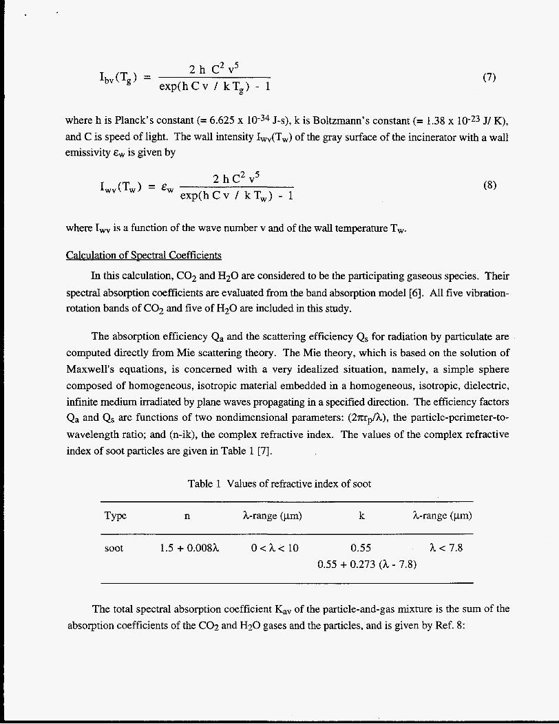
2 5 2 h C v exp(hCv / kT,) - 1 I,, (Tg ) = (7)
where h is Planck's constant (= 6.625 x J-s), k is Boltzmann's constant (= 1.38 x 10⁻²³ J/ K), and C is speed of light. The wall intensity Iwv(Tw) of the gray surface of the incinerator with a wall emissivity is given by
2 5 2 h C v exp(hCv / kT,) - 1 1 W " V W ) = Ew
where I, is a function of the wave number v and of the wall temperature T,.
Calculation of Spectral Coefficients
In this calculation, C02 and H20 are considered to be the participating gaseous species. Their spectral absorption coefficients are evaluated from the band absorption model [6]. All five vibration- rotation bands of C02 and five of H20 are included in this study.
The absorption efficiency Qa and the scattering efficiency Qs for radiation by particulate are computed directly from Mie scattering theory. The Mie theory, which is based on the solution of Maxwell's equations, is concerned with a very idealized situation, namely, a simple sphere composed of homogeneous, isotropic material embedded in a homogeneous, isotropic, dielectric, infinite medium irradiated by plane waves propagating in a specified direction. The efficiency factors Qa and Qs are functions of two nondimensional parameters: (2n;rplh), the particle-perimeter-to- wavelength ratio; and (n-ik), the complex refractive index. The values of the complex refractive index of soot particles are given in Table 1 [7].
Table 1 Values of refractive index of soot
Type n h-range (pm) k A-range (pm)
soot 1.5 + 0.008h O < h c 10 0.55 h < 7.8 0.55 + 0.273 (h - 7.8)
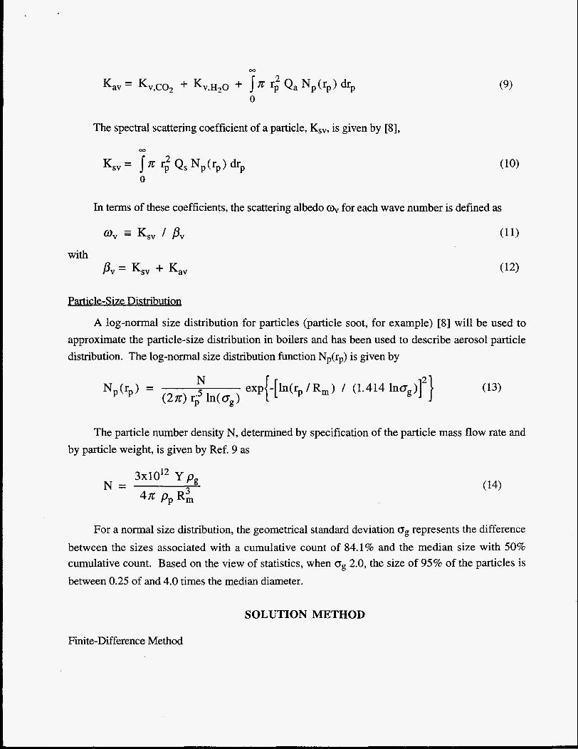
The total spectral absorption coefficient K,, of the particle-and-gas mixture is the sum of the absorption coefficients of the C02 and H20 gases and the particles, and is given by Ref. 8:
with
The spectral scattering coefficient of a particle, Ksv, is given by [8],
0
In terms of these coefficients, the scattering albedo o, for each wave number is defined as
Particle-Size Distribution
A log-normal size distribution for particles (particle soot, for example) [8] will be used to approximate the particle-size distribution in boilers and has been used to describe aerosol particle distribution. The log-normal size distribution function Np(rp) is given by
N exp{-[ln(rp / R m ) / (1.414 lnog)] 2 } Np0-p) = (2x1 r: ln<og
The particle number density N, determined by specification of the particle mass flow rate and by particle weight, is given by Ref. 9 as
3x1Ol2 Y pg N =
47G P p G
For a normal size distribution, the geometrical standard deviation og represents the difference between the sizes associated with a cumulative count of 84.1% and the median size with 50% cumulative count. Based on the view of statistics, when og 2.0, the size of 95% of the particles is between 0.25 of and 4.0 times the median diameter.
SOLUTION METHOD
Finite-Difference Method
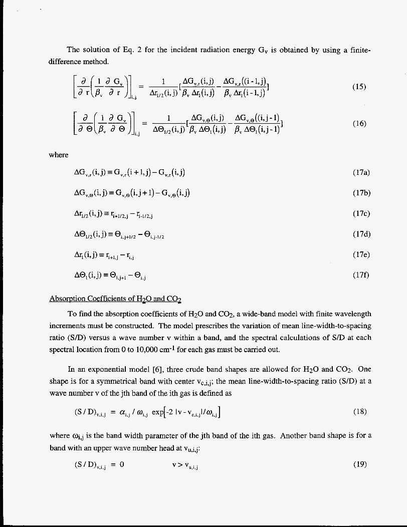
The solution of Eq. 2 for the incident radiation energy G, is obtained by using a finite- difference method.
where
A@,(i,j) =@i,j+l -@i,j
Absorption Coefficients of H7O - and co7 - To find the absorption coefficients of H20 and C02, a wide-band model with finite wavelength
increments must be constructed. The model prescribes the variation of mean line-width-to-spacing ratio (S/D) versus a wave number v within a band, and the spectral calculations of S / D at each spectral location from 0 to 10,000 cm-1 for each gas must be carried out.
In an exponential model [6], three crude band shapes are allowed for H20 and C02. One shape is for a symmetrical band with center Vc,i,j; the mean line-width-to-spacing ratio ( S D ) at a wave number v of the jth band of the ith gas is defined as
(S / D)v,i,j = / exp[-2 Iv - V ~ , ~ , ~ I / W ~ , ~ ]
where Oij is the band width parameter of the jth band of the ith gas. Another band shape is for a band with an upper wave number head at Vu,i,j:
(S / D)v.i,j = 0 V ’ Vu,i,j
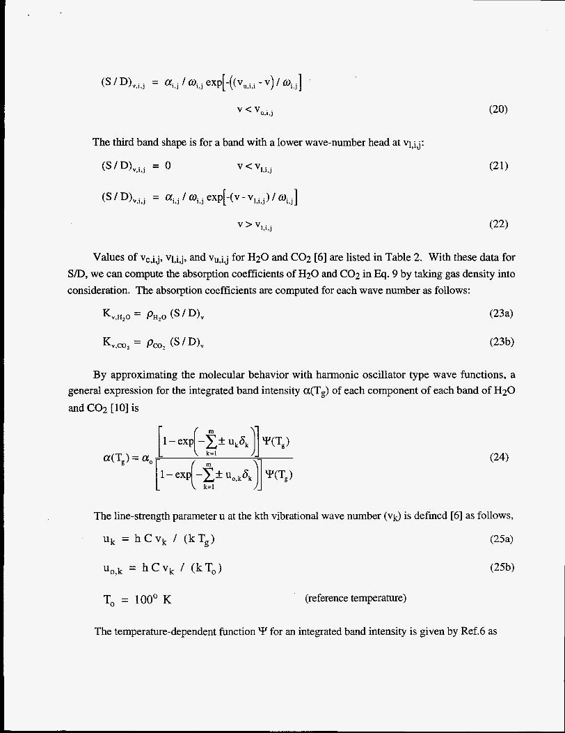
The third band shape is for a band with a lower wave-number head at V1,ij:
(S ’ D>v,i,j = 0 V < V1,i.j
Values of Vc,i,j, vl,i,j, and Vu,i,j for H20 and C02 [6] are listed in Table 2. With these data for S D , we can compute the absorption coefficients of H20 and C02 in Eq. 9 by taking gas density into consideration. The absorption coefficients are computed for each wave number as follows:
K ~ , H 2 0 = PH,O (’ D)v
By approximating the molecular behavior with harmonic oscillator type wave functions, a general expression for the integrated band intensity a(Tg) of each component of each band of H20 and C02 [ 101 is
The line-strength parameter u at the kth vibrational wave number (vk) is defined [6] as follows,
(25a)
(25b)
Uk = hCVk / (kTg)
U,,k = h C v , / (kT,)
To = 100’ K (reference temperature)
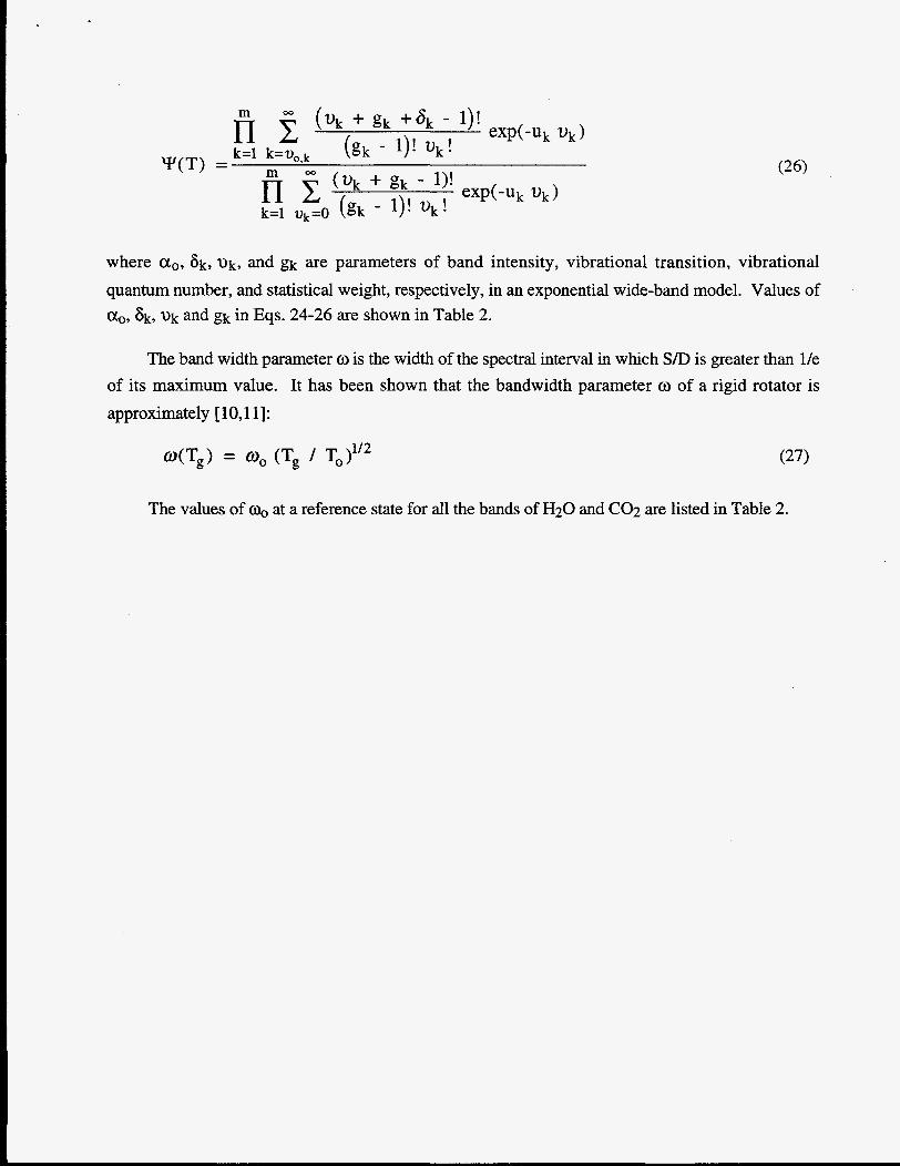
The temperature-dependent function Y for an integrated band intensity is given by Ref.6 as
"(T) =
where a,, 6k, Uk, and gk are parameters of band intensity, vibrational transition, vibrational quantum number, and statistical weight, respectively, in an exponential wide-band model. Values of a,, 6k, z)k and gk in Eqs. 24-26 are shown in Table 2.
The band width parameter o is the width of the spectral interval in which S/D is greater than l/e of its maximum value. It has been shown that the bandwidth parameter o of a rigid rotator is approximately [ l O , l 11:
O(Tg) = 0, (Tg /
The values of a, at a reference state for all the bands of H 2 0 and C02 are listed in Table 2.
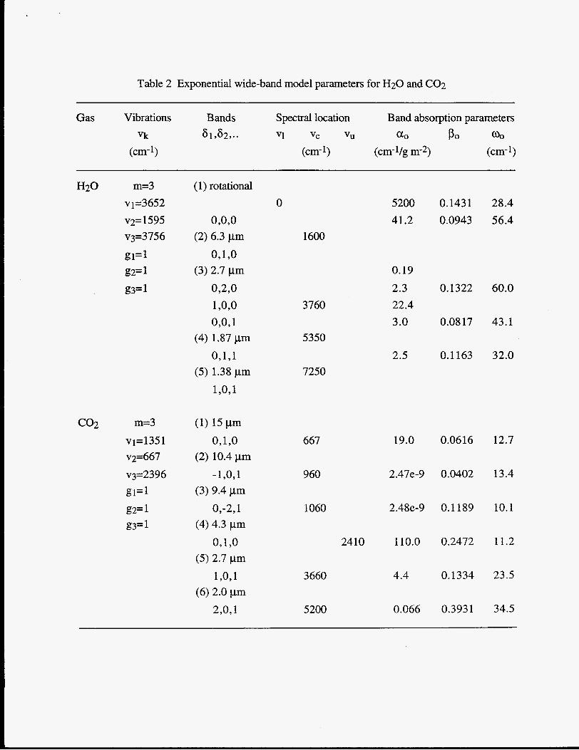
Table 2 Exponential wide-band model parameters for H20 and C02
Gas Vibrations Bands Spectral location Band absorption parameters vk 6 132,. . Vl VC VU a0 Po 0,
(em-') (cm-1) (cm-Vg m-2) (cm-1)
H20 m=3 v1=3652 v2=1595 v3=3756
g1=1 g2= 1 g3= 1
co2 m=3 vl=1351 v2=667 v3=2396 g1= 1 g2= 1 g3= 1
(1) rotational
OYOYO
OY1 Y O
OY2YO 1 Y O Y O
OYOY 1 (4) 1.87 pm
0,1Y1 (5) 1.38 pm
1 YO, 1
(2) 6.3 pm
(3) 2.7 pm
(1) 15 pm OY1 YO
(2) 10.4pm - ly0 , l
(3) 9.4 pm Oy-2,1
(4) 4.3 pm
OY1YO (5) 2.7 pm
1 YO, 1 (6) 2.0 pm
2,091
0
1600
3760
5350
7250
5200 41.2
0.19 2.3 22.4 3.0
2.5
0.143 1 0.0943
0.1322
0.08 17
0.1 163
28.4 56.4
60.0
43.1
32.0
667 19.0
960 2.47e-9
1060 2.48e-9
2410 110.0
3660 4.4
5200 0.066
0.0616
0.0402
0.1 189
0.2472
0.1334
0.393 1
12.7
13.4
10.1
11.2
23.5
34.5
Absorption and Scattering Coefficients of Particles
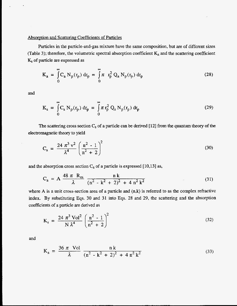
Particles in the particle-and-gas mixture have the same composition, but are of different sizes (Table 3); therefore, the volumetric spectral absorption coefficient Ka and the scattering coefficient Ks of particle are expressed as
and
The scattering cross section Cs of a particle can be derived [12] from the quantum theory of the electromagnetic theory to yield
24 n3 v2
a4 ( ;22 J.J c, =
and the absorption cross section Ca of a particle is expressed [ 10,131 as,
48n R, n k 2 2 a (n2 - k2 + 2)2 + 4 n k
Ca = A
where A is a unit cross-section area of a particle and (n,k) is referred to as the complex refractive index. By substituting Eqs. 30 and 31 into Eqs. 28 and 29, the scattering and the absorption coefficients of a particle are derived as
24 n3 Vo12 [ n22 - 1 N a4 n + 2
K, =
and
36 n Vol n k 2 2 a (n2 - k2 + 2)2 + 4 n k
K, = (33)
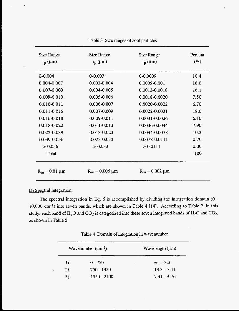
Table 3 Size ranges of soot particles
Size Range Size Range Size Range Percent rp tpm) rp tpm) rp tpm) tw
0-0.004 0-0.003 0-0.0009 10.4 0.004-0.007 0.003 -0.004 0.0009-0.00 1 16.0 0.007-0.009 0.004-0.005 0.0013-0.001 8 16.1 0.009-0.010 0.005-0.006 0 .OO 1 8 -0.0020 7.50 0.010-0.01 1 0.006-0.007 0.0020-0.0022 6.70 0.01 1-0.016 0.007-0.009 0.0022-0.003 1 18.6 0.016-0.01 8 0.009-0.01 1 0.003 1-0.0036 6.10 0.018-0.022 0.01 1-0.013 0.003 6-0.0044 7.90 0.022-0.039 0.013-0.023 0.0044-0.0078 10.3 0.039-0.056 0.023-0.033 0.0078-0.01 11 0.70
> 0.056 > 0.033 > 0.01 11 0.00 Total 100
Rm = 0.01 pm Rm = 0.006 pm Rm = 0.002 pm
D) Spectral Integration
The spectral integration in Eq. 6 is accomplished by dividing the integration domain (0 - 10,000 cm-l) into seven bands, which are shown in Table 4 [14]. According to Table 2, in this study, each band of H20 and C02 is categorized into these seven integrated bands of H20 and C02, as shown in Table 5.
Table 4 Domain of integration in wavenumber
Wavenumber (cm- 1) Wavelength (pm)
1) 0 - 750 03 - 13.3 750 - 1350 13.3 - 7.41 2)
3) 1350 - 2100 7.41 - 4.76
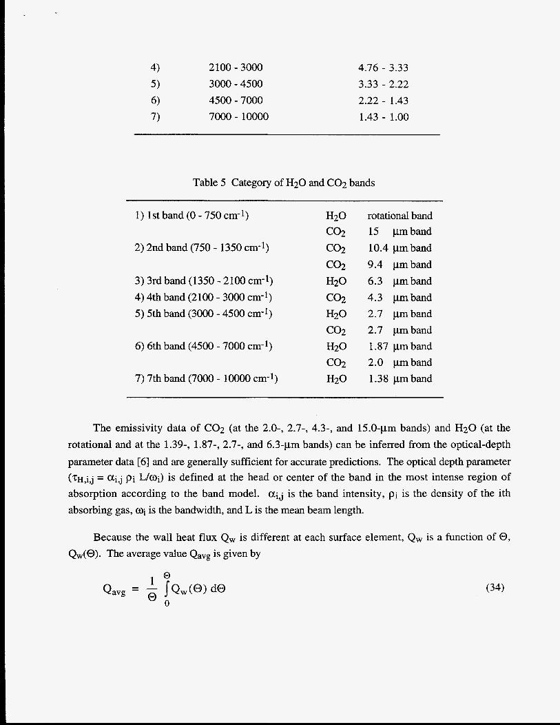
2100 - 3000 3000 - 4500 4500 - 7000 7000 - loo00
4.76 - 3.33 3.33 - 2.22 2.22 - 1.43 1.43 - 1.00
Table 5 Category of H2O and C02 bands
1) 1st band (0 - 750 cm-1)
2) 2nd band (750 - 1350 cm-1)
3) 3rd band (1350 - 2100 cm-1) 4) 4th band (2100 - 3000 cm-l) 5 ) 5th band (3000 - 4500 cm-1)
6) 6th band (4500 - 7000 cm-l)
7) 7th band (7000 - 10000 cm-1)
rotational band 15 pmband 10.4 pmband 9.4 pmband 6.3 pmband 4.3 pmband 2.7 pmband 2.7 pmband 1.87 pm band 2.0 pmband 1.38 pm band
The emissivity data of C02 (at the 2.0-, 2.7-, 4.3-, and 15.0-pm bands) and H20 (at the rotational and at the 1.39-, 1.87-, 2.7-, and 6.3-pm bands) can be inferred from the optical-depth parameter data [6] and are generally sufficient for accurate predictions. The optical depth parameter (TH,i,j = Cti j Pi L/Oi) is defined at the head or center of the band in the most intense region of absorption according to the band model. Ctij is the band intensity, pi is the density of the ith absorbing gas, wi is the bandwidth, and L is the mean beam length.
Because the wall heat flux Qw is different at each surface element, Qw is a function of 0, Qw(0). The average value Qavg is given by
Qavg (34)
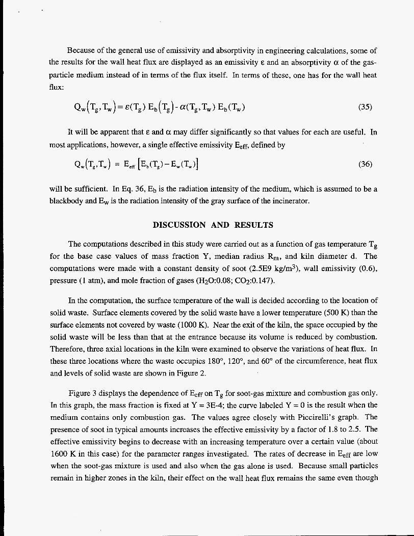
Because of the general use of emissivity and absorptivity in engineering calculations, some of the results for the wall heat flux are displayed as an emissivity E and an absorptivity a of the gas- particle medium instead of in terms of the flux itself. In terms of these, one has for the wall heat flux:
It will be apparent that E and a may differ significantly so that values for each are useful. In most applications, however, a single effective emissivity E,E, defined by
will be sufficient. In Eq. 36, Eb is the radiation intensity of the medium, which is assumed to be a blackbody and Ew is the radiation intensity of the gray surface of the incinerator.
DISCUSSION AND RESULTS
The computations described in this study were carried out as a function of gas temperature T, for the base case values of mass fraction Y, median radius Rm, and kiln diameter d. The computations were made with a constant density of soot (2.5E9 kg/m3), wall emissivity (0.6), pressure (1 atm), and mole fraction of gases (H20:0.08; C02:O. 147).
In the computation, the surface temperature of the wall is decided according to the location of solid waste. Surface elements covered by the solid waste have a lower temperature (500 K) than the surface elements not covered by waste (1000 K). Near the exit of the kiln, the space occupied by the solid waste will be less than that at the entrance because its volume is reduced by combustion. Therefore, three axial locations in the kiln were examined to observe the variations of heat flux. In these three locations where the waste occupies 180°, 120", and 60" of the circumference, heat flux and levels of solid waste are shown in Figure 2.
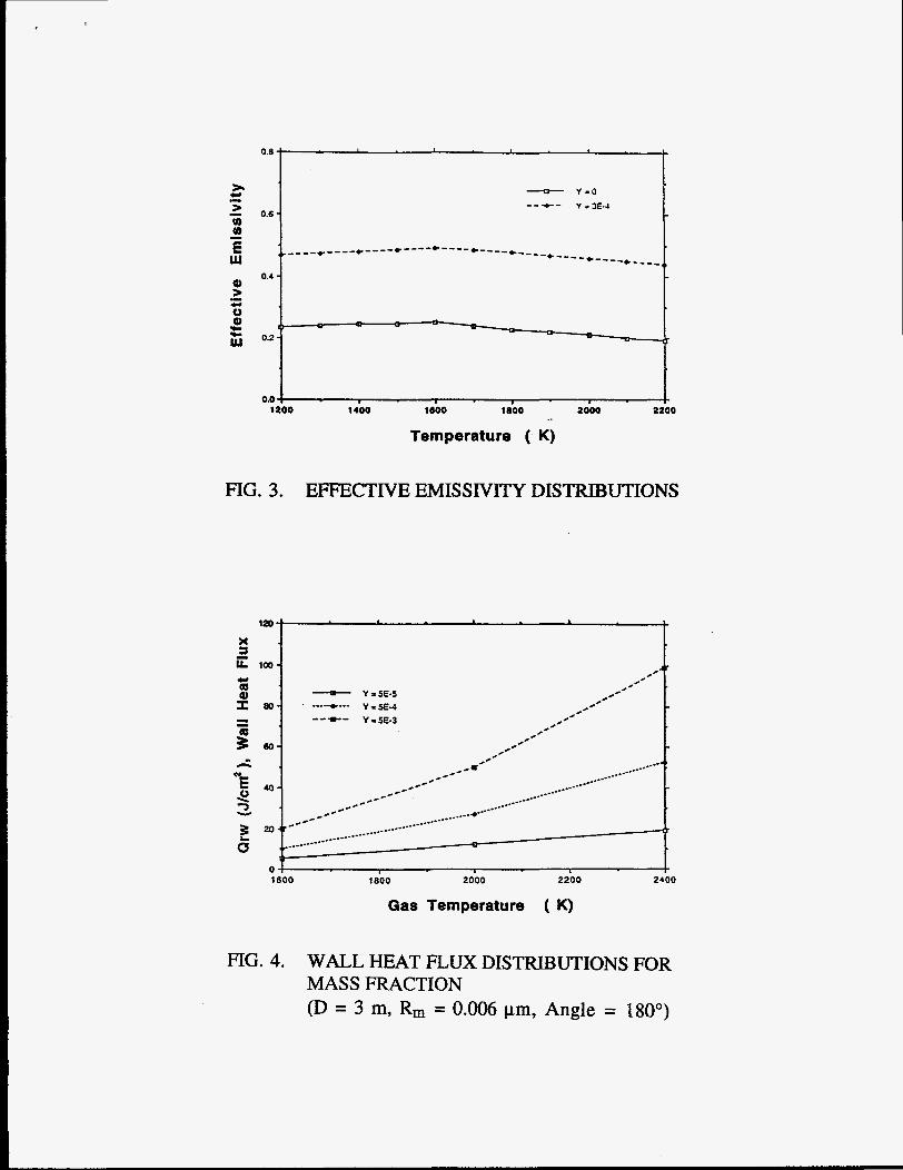
Figure 3 displays the dependence of E,ff on T, for soot-gas mixture and combustion gas only. In this graph, the mass fraction is fixed at Y = 3E-4; the curve labeled Y = 0 is the result when the medium contains only combustion gas. The values agree closely with Piccirelli's graph. The presence of soot in typical amounts increases the effective emissivity by a factor of 1.8 to 2.5. The effective emissivity begins to decrease with an increasing temperature over a certain value (about 1600 K in this case) for the parameter ranges investigated. The rates of decrease in E,ff are low when the soot-gas mixture is used and also when the gas alone is used. Because small particles remain in higher zones in the kiln, their effect on the wall heat flux remains the same even though
their temperature decreases. It is also found that the increase of the effective emissivity of the soot- gas mixture over that of the gas is insensitive to the gas temperature.
Figure 4 shows that heat flux increases with increasing mass fraction. From this graph, it appears that the heat flux rate is more sensitive to the gas temperature at a high mass fraction than at a low mass fraction, so that the mass fraction may account for some of the observed differences in radiation heat transfer of different soots. From this figure, it is also found that the amount of heat flux doubles as the mass fraction of soot is increased by a factor of 10 in the range of temperatures investigated.
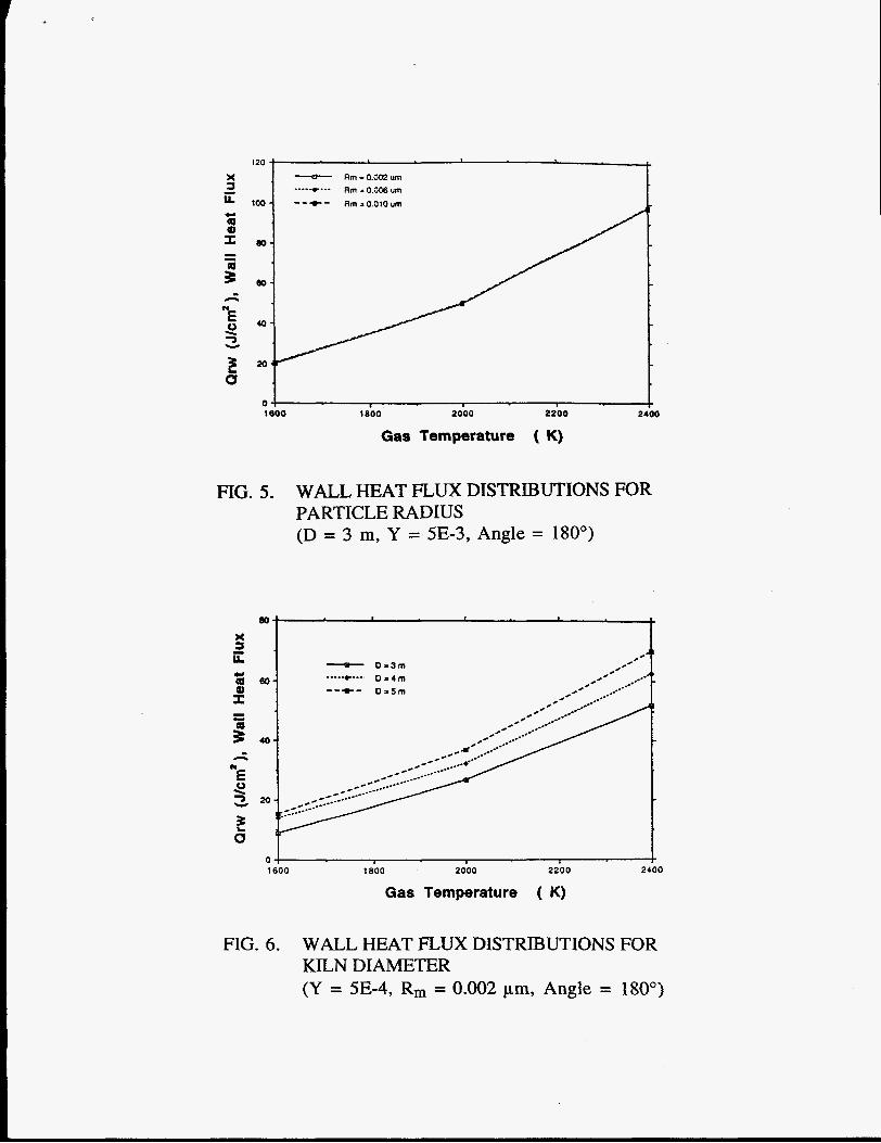
Figure 5 shows that heat flux remains the same without regard to increasing particle radius (or size distribution). This is because the soot is a Rayleigh scatter over the size range studied; therefore, heat flux is a function of the soot mass fraction rather than the size distribution. This phenomena strongly indicates that soot fineness can not be used to control radiation in a kiln incinerator.
Figure 6 shows the variations of heat flux for different kiln diameters. In this case, we concluded that heat flux increases with an increasing kiln diameter due to the effect of the optical thick limit of the medium. The increased rate of heat flux versus the temperature for different diameter is almost the same.
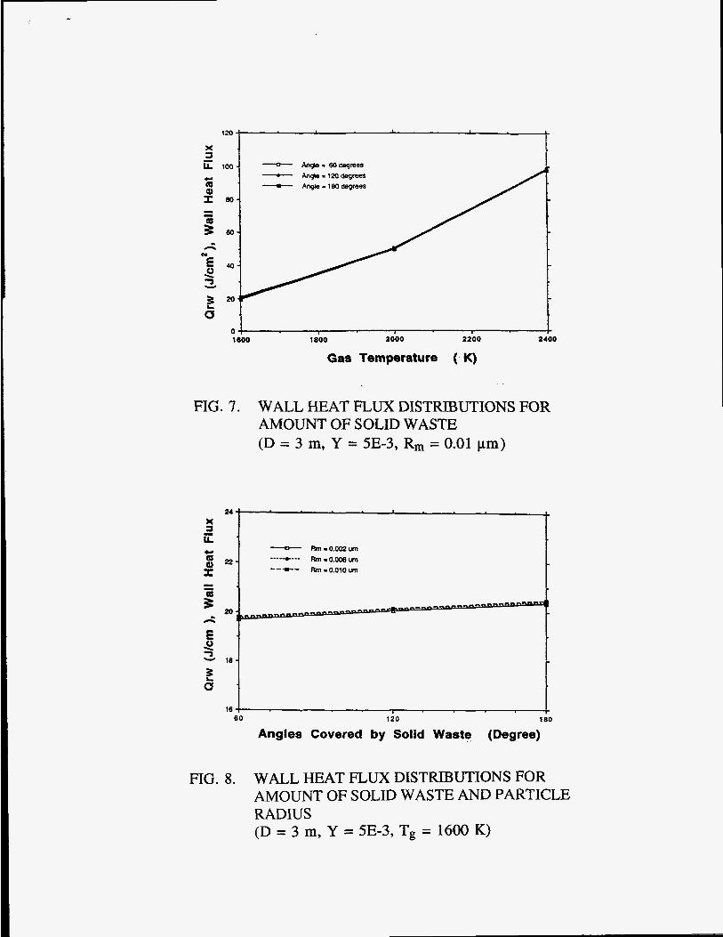
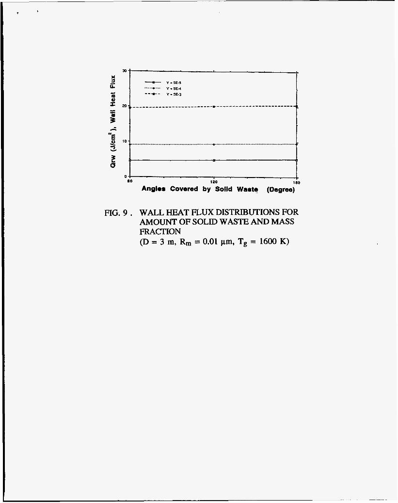
Figure 7 indicates that the existence of solid waste in a kiln incinerator does not significantly change the heat flux when the gas temperature is maintained at a constant value. Figure 8 shows that there is no correlation between the amount of solid waste and the median radius of soot for heat flux. Figure 9 emphasizes that no matter what amount of waste exists, heat flux always doubles when the mass fraction of soot is multiplied by 10.
CONCLUSIONS
(1) Particulate soot contributions to the radiation heat flux must be included in calculations to obtain
(2) Soot particles cause a comparable increase in heat flux when the mass fraction increases. (3) Heat transfer is insensitive to the soot size distribution for all mass fraction due to Rayleigh
(4) With a soot-H20-C02 mixture as the medium, heat flux is proportional to the diameter of the
quantitative models of a rotary kiln of incinerator.
scattering.
kiln due to the effect of optical thickness and is almost independent of the amount of solid waste in the incinerator.
A C C
Ca CS D d Eeff G
g I K k M m N
NP n
Q Qa
e r Ri RIn
rP S T V V
VOl Y
NOMENCLATURE
Cross-sectional area of particldtotal band absorption (m2) Speed of light ( d s ) Complex refractive index Absorption crosssection Scattering crosssection Line spacing (m) Equivalent kiln diameter Effective emissivity Incident radiation energy Statistical weight Radiation intensity Absorption coefficient Absorptive refractive index Mass of total particle (kg) Average mass of particle (kg) Number of total particles Particle-size distribution function Scattering refractive index Heat flux Absorption efficiency Scattering efficiency Equivalent kiln radius (m) Particle radius in ith size (m) Particle median radius (m) Particle radius (m) Mean line intensity Temperature (K) Volume of particle (m3) Wave number (cm-1) Volume of total particles Particle mass fraction
Greek letters P Density (kg/m3) E Emissivity
Wavelength (cm) Micrometer (10-6 m) Scattering albedohandwidth parameter Extinction coefficient Vibrational transition Integrated band intensity Frequency/vibrational quantum number Direction of propagation of radiation intensity Longitude angle of surface element under consideration Temperature dependent function for integrated band intensity Geometrical standard deviation
Subscripts a Absorption b Blackbody g Gas i j Species 0 Reference state P Particle r Location along radial direction S Scattering V Wave number (cm-1) W Wall
The ith size (or band)
REFERENCES 1.
2.
3.
4.
5 .
6 .
D. K. Edwards, “Radiation interchange in a non-gray enclosure containing an isothermal carbon dioxide and nitrogen gas mixture”, J. Heat Transfer, Vol. 84C, pp. 1-1 1, 1962.
E. Schmidt, “Messung der gesamtstrahlung das wasserdampfes bei temperaturen bis lOOOC”, Forsch. Geb. Ingenieurwes., Vol. 3, pp. 57, 1932.
M. N. Ozisik, Radiative Transfer, John Wylie & Sons Inc., New York, pp. 343-348, 1973.
K. H. Im and R. K. Ahluwalia, “Radiative transfer in spectrally-dissimilar absorbing- emitting-scattering adjacent mediums”, AIAA Journal, Vol. 21, p. 134, 1983.
E. M. Sparrow and R. D. Cess, Radiation Heat Transfer, Augmented Edition, McGraw-Hill Book Company, pp. 222-225, 1978.
D. K. Edwards and A. Balakrishnan, “Thermal radiation by combustion gases”, Int. J. Heat
7.
8 .
9.
10.
11.
12.
13.
14.
Mass Transfer, Vol. 16, pp. 25-40, 1973.
P. J. Foster and C. R. Howarth, “Optical constants of carbon and coal in the infrared”, Carbon, Vol. 6, pp. 719-729, 1968.
R. A. Piccirelli, R. K. Ahluwalia, and K. H. Im, “Radiation from pulverized coal flames”, ASME., Vol. 45, pp. 231-238, 1985.
J. M. Beer, “International flame research foundation: the effects of fineness and recirculation on combustion of low-volatile pulverized coal”, J. of the Institute of Fuel, Vol. 37, pp. 286- 313, 1964.
D. K. Edwards and W. A. Menard, “Comparison of models for correlation of total band absorption”, Applied Optics, Vol. 3, pp. 621-625, 1964.
D. K. Edwards, “Absorption of radiation by carbon monoxide gas according to the exponential wide-band model”, Applied Optics, Vol. 4, pp. 1352-1353, 1965.
M. Kerker, The Scattering of Light, Academic Press, London, 1969.
W. C. Hinds, Aerosol Technology, Library of Congress, Washington, DC.
K. H. Im and R. K. Ahluwalia, “Heat and mass transfer in MHD channels”, J. Energy, Vol. 5, p. 22, 1980.
Rotary Kiln Combustion I Gases
\ Ash
FIG. 1 . SCHEMATIC DIAGRAM OF ROTARY-KILN INCNJ%ATOR
Angle: 180 Angle: 120
Angle. 60
FIG. 2. THREE AXIAL LOCATIONS OF KILN SHOWING HEAT FLUX AND LEVELS OF SOLID WASTE
= Y - 0 --+- Y . E - 4
0 8
> 2 0.6 fn (I)
W
d) > 0 a,
CI - -
-----*---- -----*---- e---- E - _ _ -c - - - -* - e --. - - - -e - - - - 0.4
I .cI
.c 0 2
0.0 1200 1400 1600 1800 2000 2200
Temperature ( K)
FIG. 3. EFFECTIVE EMISSIVITY DISTRIBUTIONS
X - 0 1600 1 BOO 2000 2200
Gas Temperature ( K) 0
FIG. 4. WALL HEAT FLUX DISTRIBUTIONS FOR MASS FRACTION (D = 3 m, Rm = 0.006 pm, Angle = 180’)
x a ii
- n
"E 0 7 \
Y
2 a
120 -I I - Am-.0.002um
Am - 0.006 urn 1M)- Rrn = 0.010 um
..-. *... --+-
eo-
eo-
4 0 -
o i 1000 1800 2000 2200 2400
Gas Temperature ( K)
FIG. 5. WALL HEAT FLUX DISTRIBUTIONS FOR PARTICLE RADIUS (D = 3 m, Y = 5E-3, Angle = 180")
" I
1600 1800 2000 2200 2400
Gas Temperature ( K)
FIG. 6. WALL HEAT FLUX DISTRIBUTIONS FOR KILN DIAMETER (Y = 5E-4, Rm = 0.002 pm, Angle = 180")
I20 -& c
x 1 ii loo- - 60degreeS - Ang(s= tmdegrees 0 - Angle=18Odegrees al I 8 0 -
c
- - 5 60-
"E 40-
2
n n
2 3
CI 0 , r 1600 1800 2000 2200 2400
Gas Temperature ( K)
FIG. 7. WALL HEAT FLUX DISTRIBUTIONS FOR AMOUNT OF SOLID WASTE (D = 3 m, Y = 5E-3, Rm = 0.01 pm)
16 , so 120 180
Angles Covered by Solid Waste (Degree)
FIG. 8. WALL HEAT FLUX DISTRIBUTIONS FOR AMOUNT OF SOLID WASTE AND PARTICLE RADIUS (D = 3 m, Y = 5E-3, T, = 1600 K)
60
FIG. 9 .
120 1 )
Angles Covered by Solid Waste (Degree)
WALL HEAT FLUX DISTRIBUTIONS FOR AMOUNT OF SOLID WASTE AND MASS FRACTION (D = 3 m, Rm = 0.01 pm, T, = 1600 K)