computer modeling fundamentals
TRANSCRIPT

3D Computer ModelingUsing Inventor™
© 2011 Project Lead The Way, Inc.Design and Modeling

Getting Started with Inventor
When you first open Inventor, you have the option to begin a new part, assembly,
or drawing. Recently used items are available to open below. You can also open
or start new files using the ribbon at the top of the window. When starting a new
file, be sure to configure the template for the correct system, either English or
Metric.

Inventor Screen LayoutApplication Menu
• Contains common commands for creating, saving, and printing.
Quick Access Toolbar
• Provides quick access to frequently used commands
Ribbon
• A palette that displays buttons and controls used for both 2D drawing and annotation and 3D modeling and viewing
Graphics Window
• The active modeling area where parts and assemblies are created and edited
Quick Access Toolbar
Graphics
Window
Application Menu Ribbon
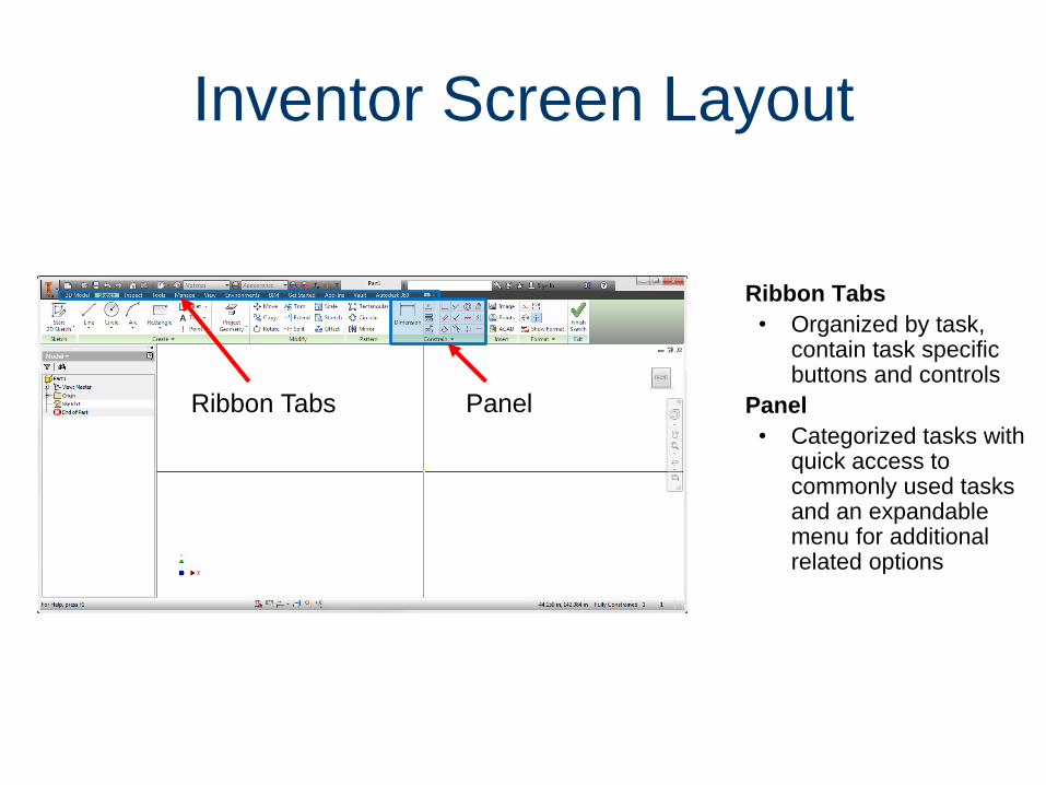
Inventor Screen Layout
Ribbon Tabs
• Organized by task, contain task specific buttons and controls
Panel
• Categorized tasks with quick access to commonly used tasks and an expandable menu for additional related options
Ribbon Tabs Panel

View Cube
• Clickable and draggableinterface that is used to switch between standard and isometric views
Navigation Bar
• On screen element that provides access to various navigation tools
Browser
• Maintains history of part, assembly, or drawing creation
3D Indicator
• Shows direction of X, Y, and Z coordinates.
• Red represents X,
• Green represents Y
• Blue represents Z directions
Browser
3D Indicator
View
Cube
Navigation Bar
Inventor Screen Layout

Mouse Buttons
• Left Mouse Button– Used to select icons,
menus, and graphics
• Right Mouse Button– Brings up additional
options
– Accepts default option
– Ends a process
• Middle Button/Wheel– Provides quick pan
and zoom functions
Right Button
Middle Wheel/Button
Left Button

Geometric ConstraintsSymbols that show alignments to capture the design intent
To use Geometric Constraints:
2. Right mouse click in Graphics
Window, then select Create Constraint
OR
1. Use the commands available
from the Constrain panel
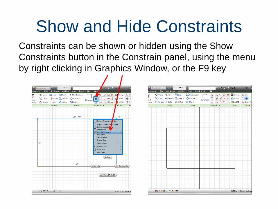
Show and Hide ConstraintsConstraints can be shown or hidden using the Show
Constraints button in the Constrain panel, using the menu
by right clicking in Graphics Window, or the F9 key

Geometric Constraint SymbolsPerpendicular Lines are at right angles
Parallel Line is parallel to other objects
Tangent Touches at one point only
Smooth Create a continuous curve
Coincident Constrains 2 points or point to curve
Concentric Arc or Circle shares center point
Collinear 2 lines lie along the same line
Equal Resizes to same radius or length
Horizontal Line is parallel to X axis
Vertical Line is parallel to Y axis
Fix Points or curves stay locked in place
Symmetry Objects align symmetrically about a line

Dynamic Viewing Functions
Pan
Zoom
Zoom Window
Zoom All
Zoom Selected
Dynamic Rotation
Look At
Located on View Ribbon Tab
Used to Zoom and Pan to
reposition the sketch
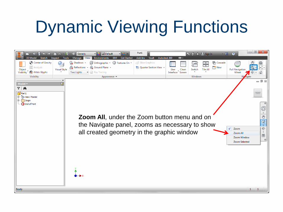
Dynamic Viewing Functions
Zoom All, under the Zoom button menu and on
the Navigate panel, zooms as necessary to show
all created geometry in the graphic window
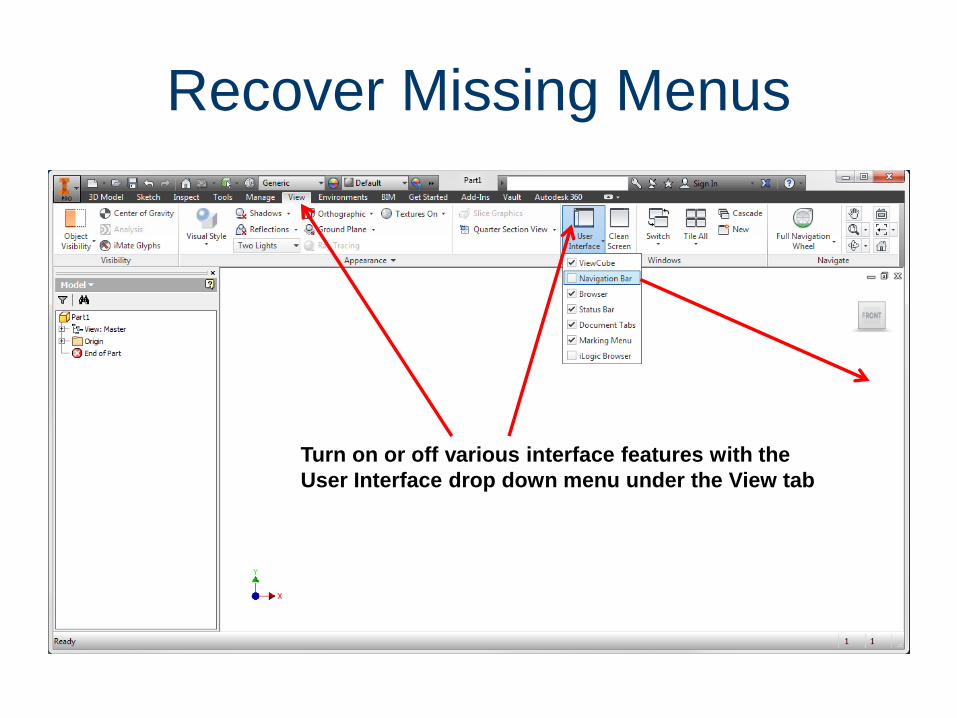
Recover Missing Menus
Turn on or off various interface features with the
User Interface drop down menu under the View tab

Expand Browser Steps
Click the plus icon to
expand each feature
and edit a sketch or
constraint.

Remove Unused Sketches
Delete extra or
unassociated
sketches and objects
from the browser.
Right click the sketch
and select Delete.

Shared Sketches
Shared sketch
Consumed in
multiple
features

Precise Input
• The Precise Input toolbar is added by expanding the Create panel and selecting Precise Input
• Create the shapes that you labeled in Activity 1.5.1 The Coordinate System and Descriptive Geometry.

Image Resources
Microsoft, Inc. (2008). Clip Art. Retrieved November 4, 2008, from
http://office.microsoft.com/en-us/clipart/default.aspx