computer intergrated heat exchanger laboratory apparatus
TRANSCRIPT

Group Number: UGP2016-14
Development of a computer integrated heat
exchanger test apparatus for the thermodynamics
laboratory of the Department FINAL REPORT
Submitted to the
DEPARTMENT OF MECHANICAL & MANUFACTURING ENGINEERING
Of the
FACULTY OF ENGINEERING
in partial fulfillment of the requirements for the
Degree of Bachelor of Science of Engineering
By MAITIPE P.C. (EG/2012/1992)
RAJASINGHE R.A.D.P.M. (EG/2012/2044)
WIMUKTHI K.A.H. (EG/2012/2123)
Approved:
DEPARTMENT OF MECHANICAL & MANUFACTURING ENGINEERING
FACULTY OF ENGINEERING
UNIVERSITY OF RUHUNA
…………………………………….
Dr. Chaminda Karunasena (Supervisor)
…………………………………….
Ms. Thamali Jayawickrama (Co-Supervisor
…………………………………….
Mrs. Kalpani Pathmasiri (Co-Supervisor)

ii
ABSTRACT
Computer integrated heat exchanger unit is most useful equipment for testing the
various kind of heat exchangers in the laboratory. Considering mechanical and manufacturing
department’s thermodynamic laboratory it still has not this kind of computer integrate heat
exchanger test apparatus. Because of its normal market price is very high around six million
rupees. The overall objective of the project is to development of a computer integrated heat
exchanger test apparatus for the thermodynamics laboratory of the Mechanical and
Manufacturing Department. This unit can use for find the heat removal rate for each material,
overall heat transfer coefficient and heat rejection for different materials. Heat exchangers are
most important parts of the machinery in the industry such as automobiles, chillers and oil
coolers.

iii
TABLE OF CONTENTS
LIST OF FIGURES .............................................................................................................. v
LIST OF TABLES ............................................................................................................... vi
INTRODUCTION ........................................................................................... 1
1.1 Background of the project ...................................................................................... 1
1.2 Background of Problem ......................................................................................... 2
1.3 Aims and objectives ............................................................................................... 2
1.4 Scope of project ..................................................................................................... 2
LITERATURE REVIEW ................................................................................ 4
2.1 Function of heat exchanger .................................................................................... 4
2.2 Theory ................................................................................................................... 5
2.2.1 Conduction ........................................................................................................ 5
2.2.2 Convection......................................................................................................... 5
2.2.3 Radiation ........................................................................................................... 6
2.2.4 Heat Exchangers ................................................................................................ 6
2.2.5 Counter Flow ..................................................................................................... 6
2.2.6 Parallel flow ...................................................................................................... 7
2.2.7 Enthalpy Balances in Heat Exchangers .............................................................. 8
2.2.8 Average Temperature of Fluid Stream................................................................ 9
2.2.9 Overall Heat Transfer Coefficient .................................................................... 10
....................................................................................................................... 12
ONGOING WORK AND DESIGN CALCULATIONS ...................................................... 12
3.1 Computer aided design of apparatus .................................................................... 12
3.2 Design calculations .............................................................................................. 13
3.2.1 Windshield pump ............................................................................................. 13
3.3 Detailed design .................................................................................................... 14
3.4 Calculations ......................................................................................................... 34

iv
3.5 Future works ........................................................................................................ 35
3.6 Time Line ............................................................................................................ 36
BIBLIOGRAPHY ............................................................................................................... 37
APPENDIX ........................................................................................................................ 38

v
LIST OF FIGURES
Figure 1: Counter flow heat exchanger ...........................................................................................................7
Figure 2: Parallel flow heat exchanger............................................................................................................8
Figure 3. CAD design of heat exchanger apparatus ...................................................................................... 12
Figure 4. Windshield washer pump .............................................................................................................. 13
Figure 5. Motor controller connect with Arduino AT-mega .......................................................................... 14
Figure 6. Test apparatus for pump calibration ............................................................................................... 14
Figure 7: Side view of Heat exchanger test apparatus ................................................................................... 15
Figure 8: Top view of heat exchanger........................................................................................................... 16
Figure 9: fabricated model ........................................................................................................................... 18
Figure 10: double pipe heat exchanger ......................................................................................................... 18
Figure 11: Hot water tank with heater........................................................................................................... 19
Figure 12: Cold water tank with pump ......................................................................................................... 19
Figure 13: wind shield pump ........................................................................................................................ 20
Figure 14: Temperature sensor ..................................................................................................................... 20
Figure 15: Motor controller .......................................................................................................................... 21
Figure 16: arduino mega .............................................................................................................................. 21
Figure 17: 5 channel selector switch ............................................................................................................. 22
Figure 18: Electrical layout .......................................................................................................................... 22
Figure 19: labview program ......................................................................................................................... 24
Figure 20: Lab view interface ....................................................................................................................... 25
Figure 21: Simulation model ........................................................................................................................ 25
Figure 22: Parallel flow ................................................................................................................................ 34
Figure 23: time Line ..................................................................................................................................... 36

vi
LIST OF TABLES
Table 1. Results of water pump calibration ................................................................................................... 13
Table 2: Conceptual design .......................................................................................................................... 17

1
INTRODUCTION
1.1 Background of the project
Exchangers are easily one of the most important and widely used pieces of process
equipment found in industrial sites. Regardless of the particular industry in question, it will
likely require some type of temperature regulation. Exchangers may be used for either
heating or cooling, however, in the industrial sector, particularly within plants and
refineries, they are overwhelmingly used for cooling. Heat exchangers have a very broad
range of industrial applications. They are used as components of air conditioning and
cooling systems or of heating systems. Different types of heat exchangers work in different
ways, that practical unit has double pipe heat exchangers use different flow arrangements,
equipment, and design feature
The double-pipe heat exchanger is one of the simplest types of heat exchangers. It is
called a double-pipe exchanger because one fluid flows inside a pipe and the other fluid
flows between that pipe and another pipe that surrounds the first. This is a concentric tube
construction. Flow in a double-pipe heat exchanger can be co-current or counter-current.
There are two flow configurations: co-current is when the flow of the two streams is in the
same direction, counter current is when the flow of the streams is in opposite directions.
Heat Exchangers are generally classified by one of the following four metrics,
1. The nature of the heat exchange process
2. The physical state of the fluids
3. The heat exchanger’s flow arrangement
4. The design and construction of the heat exchanger

2
1.2 Background of Problem
A range of small-scale heat exchangers, designed to illustrate the principles and
techniques of indirect heat transfer between fluid streams. Different types of heat
exchanger can be mounted on a common bench-top service unit. Small scale versions of
commonly used industrial heat exchangers are available (including plate, tubular and ‘shell
and tube’) for analysis and comparison. The equipment is controlled by a user supplied
personal computer, which serves as the operator interface. Full data logging, control and
educational software is supplied with the equipment. In addition, the equipment has been
fitted with failsafe systems, including a watchdog circuit, which allows for safe operation
from a remote computer.
1.3 Aims and objectives
The overall objective of the project is to development of a computer integrated heat
exchanger test apparatus for the thermodynamics laboratory of the Mechanical and
Manufacturing Department.
- Test different type of heat exchangers at one unit.
- The market cost of this type of apparatus is expensive. But. Hope to made it in low
cost with same functions.
1.4 Scope of project
Computer integrate heat exchanger laboratory apparatus is fabricated to thermodynamic
laboratory for test various kind of heat exchange parameters and compare different type of
heat exchangers performance.
The following degrees of freedom can be varied in this experiment:
Hot water feed temperature and flow rate
Cold water feed temperature and flow rate
Heat exchanger type (tubular, shell & tube, or plate)
Flow direction (parallel or counter-flow)
Heat exchanger configurations; parallel vs. counter-current flow
Logarithmic Mean Temperature Difference (LMTD) and Effectiveness-NTU
methods for analysis of heat exchangers

3
We hope to investigate effects of these variables on the following performance indicators:
Return temperatures and of the hot and cold water
Heat flow rate (𝑞)
Overall heat transfer coefficient (𝑈)
The equipment is controlled by a user supplied personal computer, which serves as the
operator’s interface. Full data logging, controlling software is communicating with the
equipment. The “Arduino” and “LabVIEW” software were used as a major controlling
software.
Arduino is an open-source hardware, open-source software, and microcontroller-
based kits for building digital devices and interactive objects that can sense and
control physical devices.
LabVIEW (Laboratory Virtual Instrument Engineering Workbench) is a system-
design platform and development environment for a visual programming language.
In this project we will fabricate a lab-scale model and simulator of a computer integrated
heat exchanger test apparatus.

4
LITERATURE REVIEW
Heat exchanger is a device, such as an automobile radiator, used to transfer heat from a fluid on one
side of a barrier to a fluid on the other side without bringing the fluid into direct contact. Usually,
this barrier is made from metal which has good thermal conductivity in order to transfer heat
effectively from one fluid to another fluid. Besides that, heat exchanger can be defined as any of
several devices that transfer heat from a hot to a cold fluid. In engineering practical, generally, the
hot fluid is needed to cool by the cold fluid. For example, the hot vapor is needed to be cool by
water in condenser practical. Moreover, heat exchanger is defined as a device used to exchange heat
from one medium to another often through metal walls, usually to extract heat from a medium
flowing between two surfaces. In automotive practice, radiator is used as heat exchanger to cool
hot water from engine by air surrounding same like intercooler which used as heat exchanger to
cool hot air for engine intake manifold by Air surrounding. Usually, this device is made from
aluminum since it is lightweight and good thermal conductivity.
2.1 Function of heat exchanger
Heat exchanger is a special equipment type because when heat exchanger is directly fired by a
combustion process, it becomes furnace, boiler, heater, tube-still heater and engine. Vice versa,
when heat exchanger makes a change in phase in one of flowing fluid such as condensation of steam
to water, it becomes a chiller, evaporator, sublimate, distillation-column reboiler, still, condenser
or cooler-condenser. Heat exchanger may be designed for chemical reactions or energy-generation
processes which become an integral part of reaction system such as a nuclear reactor, catalytic
reactor or polymer. Normally, heat exchanger is used only for the transfer and useful elimination or
recovery of heat without changed in phase. The fluids on either side of the barrier usually liquids
but they can be gasses such as steam, air and hydrocarbon vapor or can be liquid metals such as
sodium or mercury. In some application, heat exchanger fluids may use fused salts [2].

5
2.2 Theory
The process of heat exchange between two fluids that are at different temperatures and separated
by a solid wall occurs in many engineering applications. The device used to implement this
exchange is called a heat exchanger, and specific applications may be found in space heating and
air-conditioning, power production, waste heat recovery and chemical processing. The flow of heat
from a fluid through a solid wall to another fluid is often encountered in chemical engineering
practice. The heat transferred may be latent heat accompanying phase changes such as condensation
or vaporization, or it may be sensible heat coming from increasing or decreasing the temperature of
a fluid without phase change. Heat transfer is the movement of energy due to a temperature
difference. There are three physical mechanisms of heat transfer; conduction, convection, radiation.
All three modes may occur simultaneously in problems of practical importance.
2.2.1 Conduction
Heat conduction is the transfer of heat from one part of a body to another part of the same body or
from one body to another body in physical contact with it, without appreciable displacement of the
particles of the body. Energy transfer by conduction is accomplished in two ways. The first
mechanism is that of molecular interaction, in which the greater motion of a molecule at a higher
energy level imparts energy to adjacent molecules at lower energy levels. This type of transfer is
present, to some degree, in all systems in which a temperature gradient exists and in which
molecules of a solid, liquid, or gas are present. The second mechanism of conduction heat transfer
is by free electrons. The free-electron mechanism is significant primarily in pure metallic
Solids: the concentration of free electrons varies considerably for alloys and becomes very low for
nonmetallic solids. The distinguishing feature of conduction is that it takes place within the
boundaries of a body, or across the boundary of a body into another body placed in contact with the
first, without an appreciable displacement of the matter comprising the body.
2.2.2 Convection
Heat transfer by convection occurs in a fluid by the mixing of one portion of the fluid with another
portion due to gross movements of the mass of fluid. The actual process of energy transfer from
one fluid particle or molecule to another is still one of conduction, but the energy may be transported
from one point in space to another by the displacement of the fluid itself. Convection can be further
subdivided into free convection and forced convection. If the fluid is made to flow by an external
agent such as a fan or pump, the process is called forced convection. If the fluid motion is caused

6
by density differences which are created by the temperature differences existing in the fluid mass,
the process is termed free convection or natural convection. The motion of the water molecules in
a pan heated on a stove is an example of a free convection process. The important heat transfer
problems of condensing and boiling are also examples of convection, involving the additional
complication of a latent heat exchange. It is virtually impossible to observe pure heat conduction in
a fluid because as soon as a temperature difference is imposed on a fluid, natural convection currents
will occur due to the resulting density differences.
2.2.3 Radiation
Thermal radiation describes the electromagnetic radiation that is emitted at the surface of a body
which has been thermally excited. This electromagnetic radiation is emitted in all directions and
when it strikes another body part may be reflected part may be transmitted and part may be
absorbed. Thus heat may pass from one body to another without the need of a medium of transport
between them. In some instances there may be a separating medium, such as air which is unaffected
by this passage of energy. The heat of the sun is the most obvious example of thermal radiation.
2.2.4 Heat Exchangers
Heat exchangers are typically classified according to flow arrangement and type of construction. In
the first classification flow can be count flow or parallel Heat exchangers can also be classified
based on their configuration as double pipe and shell & tube heat exchangers. Double pipe is the
Simplest form of heat exchanger and consists of two concentric tubes carrying the hot and Cold
fluids. Heat is transferred to from one fluid in the inner tube from to the other fluid in the
Outer annulus across the metal tube wall that separates the two fluids.
2.2.5 Counter Flow
In the countercurrent flow heat exchangers, the fluids enter at opposite ends, flow in opposite
Directions, and leave at opposite ends. The temperatures are denoted as follows:
T1: Temperature of entering hot fluid, °C
T2: Temperature of mid-position hot fluid, °C
T3: Temperature of leaving hot fluid, °C
T4: Temperature of entering cold fluid, °C
T5: Temperature of mid-position cold fluid, °C
T6: Temperature of leaving cold fluid, °C

7
Distance along the heat exchanger
The approaches are
𝑇1 − 𝑇6 = Δ𝑇1
𝑇3 − 𝑇4 = Δ𝑇2
2.2.6 Parallel flow
In the parallel flow heat exchanger, the hot and cold fluids enter at the same end, flow in the same
direction, and leave at the same end. The temperature practices across the tube length are shown in the
below figure
Figure 1: counter flow heat exchanger

8
The approaches are,
𝑇1 − 𝑇6 = Δ𝑇1
𝑇3 − 𝑇4 = Δ𝑇2
2.2.7 Enthalpy Balances in Heat Exchangers
To design or predict the performance of a heat exchanger, it is essential to determine the heat lost
to the surrounding for the analyzed configuration. A parameter can be defined to quantify the
percentage of losses or gains. Such a parameter may readily be obtained by applying overall energy
balances for hot and cold fluids. In heat exchangers there is no shaft work and mechanical potential
and mechanical kinetic energies are small in comparison with the other terms in the energy balance
equation. If Qe is the heat power emitted from hot fluid, while Qa is the heat power absorbed by
cold fluid, and also if constant specific heats are assumed
𝑄𝑒 = �̇�ℎ(ℎ,𝑖−ℎ,𝑜) = �̇�ℎ𝐶𝑝ℎ(𝑇ℎ,𝑖−𝑇ℎ,𝑜)
𝑄𝑎 = �̇�𝑐(ℎ𝑐,𝑖−ℎ𝑐,𝑜) = �̇�𝑐𝐶𝑝𝑐(𝑇𝑐,𝑖−𝑇𝑐,𝑜)
Figure 2: parallel flow heat exchanger

9
Where,
𝑚 ̇ℎ, �̇�𝑐 : mass flow rate of hot and cold fluid, respectively.
ℎ, 𝑖, ℎ, : inlet and outlet enthalpies of hot fluid, respectively.
ℎ𝑐, 𝑖, ℎ𝑐, : inlet and outlet enthalpies of cold fluid, respectively.
𝑇ℎ,, 𝑇ℎ,𝑜 : inlet and outlet temperatures of hot fluid, respectively.
𝑇ℎ,, 𝑇ℎ,𝑜 : inlet and outlet temperatures of cold fluid, respectively.
𝐶𝑝ℎ, 𝐶𝑝 : specific heats of hot and cold fluid, respectively.
𝐻𝑒𝑎𝑡 𝑝𝑜𝑤𝑒𝑟 𝑔𝑎𝑖𝑛 𝑜𝑟 𝑙𝑜𝑠𝑠=|𝑄𝑒|−|𝑄𝑎|
Percentage P of losses or gains is,
𝑃=|𝑄𝑎||𝑄𝑒|×100
If the heat exchanger is well insulated, Qe and Qa should be equal. Then, the heat lost by the hot
fluid is gained by the cold fluid Qa = -Qe
In practice these differ due to heat losses or gains to/from the environment. If the average cold fluid
temperature is above the ambient air temperature then heat will be lost to the surroundings resulting
In P < 100%. If the average cold fluid temperature is below the ambient temperature, heat will be
gained resulting P > 100%.
2.2.8 Average Temperature of Fluid Stream
When a fluid is being heated, the temperature of the fluid is a maximum at the wall of the heating
surface and decreases toward the center of the stream. If the fluid is being cooled the temperature
is a minimum at the wall and increases toward the center. Because the temperature difference
between the hot and cold fluid streams varies along the length of the heat exchanger it is necessary
to derive an average temperature difference from which heat transfer calculations can be performed.
This average temperature difference is called the Logarithmic Mean Temperature Difference
(LMTD)
∆𝑇𝑙𝑚 = ∆𝑇1− ∆𝑇2
ln (∆𝑇1∆𝑇2
) ………….. (01)

10
2.2.9 Overall Heat Transfer Coefficient
It can be expected that the heat flux may be proportional to a driving force. In heat flow, the driving
force is taken as Th - Tc where Th is the average temperature of the hot fluid and Tc is that of the
cold fluid. The quantity Th - Tc is the overall temperature difference. It is denoted by ΔT. that T
can vary considerably from point to point along the tube, and therefore since the heat flux is
proportional to ΔT, the flux also varies with tube length. It is necessary to start with a differential
equation, by focusing attention on a differential area dA through which a differential heat flow dq
occurs under the driving force of a local value of ΔT. The local flux is then dx/dA and is related to
the local value of ∆𝑇𝑙𝑚
………………. (02)
The quantity U, defined by as a proportionality factor between dq/dA and ΔT, is called the local
overall heat-transfer-coefficient. To complete the definition of U in a given case, it is necessary to
specify the area. If A is taken as the outside tube area Ao, U becomes a coefficient based on that
area and is written Uo. Likewise, if the inside area Ai is chosen, the coefficient is also based on that
area and is denoted by Ui. Since ΔT and dq are independent of the choice of area, it follows that
………………… (03)
Where Di and Do are the inside and outside tube diameters, respectively. To apply Eq. 02 to the
entire area of a heat exchanger the equation must be integrated. The assumptions are ,
1. The overall coefficient U is constant.
2. The specific heats of the hot and cold fluids are constant.
3. Heat exchange with the surroundings is negligible.
The most questionable of these assumptions is that of a constant overall coefficient. The coefficient
does in fact vary with the temperatures of the fluids, but its change with temperature is gradual, so
that when the temperature ranges are moderate, the assumption of constant U is not seriously in
error.
Assumptions 2 and 4 imply that if Tc and Th are plotted against q, straight lines are obtained. Since
Tc and Th vary linearly with q, ΔT does likewise, and d(ΔT)/dq the slope of the graph of ΔT vs. q,
is constant. Therefore:

11
The variables ΔT and A can be separated, and if U is constant, the equation can be integrated over
the limits AT and 0 for A and ΔT2 and ΔT1 for ΔT, where AT is the total area of the heat-transfer
surface.
Thus,
Total heat transfer surface area in the tubular heat exchanger is defined as
Effectiveness-Net Transfer Units (NTU) Method
The heat exchanger effectiveness ε is define as,
ε = 𝑞
𝑞𝑚𝑎𝑥
𝑞𝑚𝑎𝑥 = 𝐶𝑚𝑖𝑛(𝑇ℎ,𝑖 − 𝑇𝑐,𝑖 )
𝑁𝑇𝑈 = 𝑈𝐴
𝐶𝑚𝑖𝑛
𝑇ℎ,𝑖, 𝑇𝑐,𝑖 = Temperature difference between hot and cold point
𝐶𝑚𝑖𝑛 = Heat capacity rate

12
ONGOING WORK AND DESIGN CALCULATIONS
3.1 Computer aided design of apparatus
The CAD model of heat exchanger lab apparatus was designed by using a solidwork software to
get basic idea of computer integrated heat exchanger test apparatus. Following figure shown how
is going to fabricate the apparatus.
Basic components of heat exchanger test apparatus as follows,
1 – Cold water storage tank
2 – Hot water storage tank
3 – 12V power supply
4 – Windshields water pump
5 – Thermal sensor (DS18B20)
6 – Microcontroller (Arduino)
7 – Motor controller
8 – Heat exchanger
Figure 3. CAD design of heat exchanger apparatus

13
3.2 Design calculations
3.2.1 Windshield pump
We were planning to fabricate heat exchanger test apparatus according to our basic CAD design as
shown above figure. First of all, we were calibrated windshield washer pump with respect to
different PWMs such as 50,100,150,200 and 250.
PWM VOLUME(ml) TIME(s) FLOW RATE (𝑚𝑙𝑠⁄ ) CURRENT(A) VOLTAGE (V)
50 600 121 4.95 0.43 12.0
100 600 85 7.06 0.72 12.0
150 600 69 8.70 1.16 9.0
200 600 54.2 11.07 1.38 9.0
250 600 37 16.22 1.65 9.0
Figure 4. Windshield washer pump
Table 1. Results of water pump calibration

14
3.3 Detailed design
Computer integrated heat exchanger practical unit was fabricated to study about variation
of heat transfer through the copper tube industrial was used for heating the water for supply to
Figure 5. Motor controller connect with Arduino AT-mega
Figure 6. Test apparatus for pump calibration

15
cupper tube that heater temperature was controlled by using inbuilt thermostat valve and for
circulation of hot water used the 12V wind shield pump that pump flow rate was controlled by
PWM signals. Cold water supplied by using gravity force.
Figure 7: Side view of Heat exchanger test apparatus

16
1 – DC power supply
2 – Wind shield pump
3 – Hot water inlet port
4 – Hot water outlet port
5 – Cold water inlet port
6 – Cold water outlet port
7 – Thermal sensor (DS18B20)
8 – AC power supply for Heater
Temperature sensors were mounted hot in and hot out chamber of inner pipe and cold in
cold out chamber of outer pipe then that temperature reading directly get lab view interface through
the arduino mega board.
Figure 8: Top view of heat exchanger

17
Computer integrated heat exchanger unit
Heat exchangers
1.Double pipe
2.Shell and tube
3.Plate type
Double pipe
Pumps
230 ac pump
12v dc pump
Wind shield pump
12V dc pump
12V dc wind shielded pump
Sensors
Thermocouple
LM 35
Ds18b20
DS18b20 sensor
Micro controller
Arduino
PIC
Arduino mega
Flow controller
VFD drive
L 298N
L298N
Software
Lab View
Visual basic
LabView
Module
NI 9211
Max 6675
The monitoring unit consist of following two software
• Arduino- to get temperature from sensors
• Labview-monitering temperature and plotting the graph
Conceptual Design
Mass flow rate Cold water Hot water
97.34(ml/s) 16.22(ml/s)
Table 2: conceptual design

18
Fabrication model
Design components
Double pipe heat exchanger unit
Double pipe heat exchanger include copper inner tube and PVC outer tube each of hot in
hot out and cold in cold out temperature’s measured by using (ds18b20) sensor.
Figure 9: fabricated model
Figure 10: double pipe heat exchanger
19
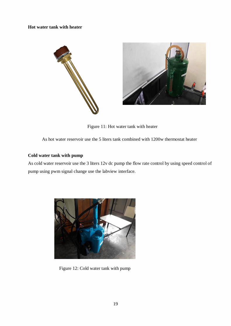
Hot water tank with heater
As hot water reservoir use the 5 liters tank combined with 1200w thermostat heater
Cold water tank with pump
As cold water reservoir use the 3 liters 12v dc pump the flow rate control by using speed control of
pump using pwm signal change use the labview interface.
Figure 11: Hot water tank with heater
Figure 12: Cold water tank with pump

20
Wind shield pump
This pump is use to circulate the hot water in heat exchanger the flow rate is controlled by changing
the PWM signals
Temperature sensors (ds1820)
To measure the temperature values of specific points, here was used a DS18B20 three wire
temperature sensor. Some specifications of temperature sensor as stainless steel tube encapsulation
waterproof and moisture proof. For this sensor signal pin and VCC pin should short circuit with
4.7K resistors
Stainless steel tube size: Approximately 6*50mm (Diameter*Length)
Operating temperature range: -55°C - +125°C (-67°F - +257°F)
Accuracy over the range of -10°C to +85°C: ±0.5°C.
Figure 13: wind shield pump
Figure 14: Temperature sensor

21
Motor controller (L298N)
L298N H-bridge IC that can allows you to control the speed and direction of two motors, control
one bipolar steeper motor with ease
Arduino mega
The arduino mega is microcontroller board on the AT mega 1280 it has 54 digital
input/output pins
Analog input pins: 16
DC current for 3.3V pins: 50mA
DC current per I/O pins: 40mA
Digital I/O pins : 54 (of which provided PWM output)
Figure 15: Motor controller
Figure 16: arduino mega

22
5 channel selector switch
This switch can select the position that switch is use to get the different temperature values on the
lab view interface
Electrical layout
Figure 17: 5 channel selector switch
Figure 18: Electrical layout

23
Lifabase Firmware
// Standard includes. These should always be included.
#include <Wire.h>
#include <SPI.h>
#include <Servo.h>
#include "LabVIEWInterface.h"
#include <OneWire.h> //For use with OneWire devices
#include <DallasTemperature.h> //For use with Maxim/Dallas DS18B20 or similiar
Temperature devices
//Defines for OneWire and Dallas Temperature
#define ONE_WIRE_BUS 2
//Setup a oneWire instance to communicate with any OneWire devices
OneWire oneWire(ONE_WIRE_BUS);
//Pass our oneWire reference to Dalls Temperature
DallasTemperature sensors(&oneWire);
/************************************************************************
*********
** setup()
**
** Initialize the Arduino and setup serial communication.
**
** Input: None
** Output: None
******************************************************************************
***/
void setup()
{
// Initialize Serial Port With The Default Baud Rate
syncLV();

24
// Place your custom setup code here
sensors.begin();
sensors.setResolution(9);
}
/************************************************************************
*********
** loop() ** ** The main loop. This loop runs continuously on the Arduino
Labview program
Digital port 8 and 9 port of arduino use for controlling the pumps speed through the L298N motor
controller as the speed controller use the knob button in lab view interface with indicator digital
port 2 that port is defined by (lifabase) use the (ds18b20) temperature sensors that temperature
parameters get the thermometer table and graph in lab view interface
Figure 19: labview program

25
Lab view interface
This interface can read the each temperature values without any delay and also it can get the graph
how to varying temperature with time and also it can control the both hot and cold water flow
rates.
Simulation model
Figure 20: Lab view interface
Figure 21: Simulation model

26
CAD version SOLIDWORKS 2016 SP0.1
CPU speed 2401 MHz
General Info
Model Assem11k.SLDASM
Project name double pipe
Project path D:\final year project\design\2
Units system SI (m-kg-s)
Analysis type Internal
Exclude cavities without flow
conditions
On
Coordinate system Global coordinate system
Reference axis X
INPUT DATA
Global Mesh Settings
Automatic initial mesh: On
Result resolution level: 3
Advanced narrow channel refinement: Off
Refinement in solid region: Off
Geometry Resolution
Evaluation of minimum gap size: Automatic
Evaluation of minimum wall thickness: Automatic
Computational Domain
Size
X min -0.023 m
X max 0.480 m
Y min 0.260 m
Y max 0.363 m

27
Z min 0.364 m
Z max 0.394 m
Boundary Conditions
2D plane flow None
At X min Default
At X max Default
At Y min Default
At Y max Default
At Z min Default
At Z max Default
Physical Features
Heat conduction in solids: On
Heat conduction in solids only: Off
Radiation: Off
Time dependent: Off
Gravitational effects: Off
Rotation: Off
Flow type: Laminar only
Cavitation: Off
High Mach number flow: Off
Default roughness: 0 micrometer
Default outer wall condition: Adiabatic wall
Initial Conditions
Thermodynamic parameters Static Pressure: 101325.00 Pa
Temperature: 293.20 K
Velocity parameters Velocity vector
Velocity in X direction: 0 m/s
Velocity in Y direction: 0 m/s
Velocity in Z direction: 0 m/s

28
Solid parameters Default material: Copper Tungsten
(Cu10/W90)
Initial solid temperature: 293.20 K
Material Settings
Fluids
Water
Solid Materials
Copper Tungsten (Cu10/W90) Solid Material 1
Boundary Conditions
Inlet Volume Flow 2
Type Inlet Volume Flow
Faces Face<1>@Part4-1
Coordinate system Face Coordinate System
Reference axis X
Flow parameters Flow vectors direction: Normal to face
Volume flow rate: 0.0001 m^3/s
Fully developed flow: No
Inlet profile: 0
Thermodynamic parameters Temperature: 323.00 K
Inlet Volume Flow 1
Type Inlet Volume Flow
Faces Face<2>@Part2-1
Coordinate system Face Coordinate System
Reference axis X
Flow parameters Flow vectors direction: Normal to face
Volume flow rate: 0.0002 m^3/s
Fully developed flow: No
Inlet profile: 0
Thermodynamic parameters Temperature: 303.00 K

29
Environment Pressure 1
Type Environment Pressure
Faces Face<3>@Part2-2
Coordinate system Face Coordinate System
Reference axis X
Thermodynamic parameters Environment pressure: 101325.00 Pa
Temperature: 304.00 K
Environment Pressure 2
Type Environment Pressure
Faces Face<4>@Part4-1
Coordinate system Face Coordinate System
Reference axis X
Thermodynamic parameters Environment pressure: 101325.00 Pa
Temperature: 320.00 K
Calculation Control Options
Finish Conditions
Finish Conditions If one is satisfied
Maximum travels 4
Goals convergence Analysis interval: 5.000000e-001
Solver Refinement
Refinement: Disabled
Results Saving
Save before refinement On

30
Advanced Control Options
Flow Freezing
Flow freezing strategy Disabled
RESULTS
General Info
Iterations: 217
CPU time: 117 s
Log
Mesh generation started 01:44:26 , Nov 20
Mesh generation normally finished 01:44:31 , Nov 20
Preparing data for calculation 01:44:32 , Nov 20
Calculation started 0 01:44:34 , Nov 20
Calculation has converged since the
following criteria are satisfied: 216
01:46:30 , Nov 20
Max. travel is reached 216
Calculation finished 217 01:46:31 , Nov 20
Calculation finished 217 01:48:44 , Nov 20
Calculation finished 217 11:12:53 , Nov 20
Calculation finished 217 11:14:55 , Nov 20
Calculation Mesh
Basic Mesh Dimensions
Number of cells in X 61
Number of cells in Y 13
Number of cells in Z 4
Number Of Cells
Cells 35779
Fluid cells 10206
Solid cells 25573
31
Partial cells 8504
Irregular cells 0
Trimmed cells 0
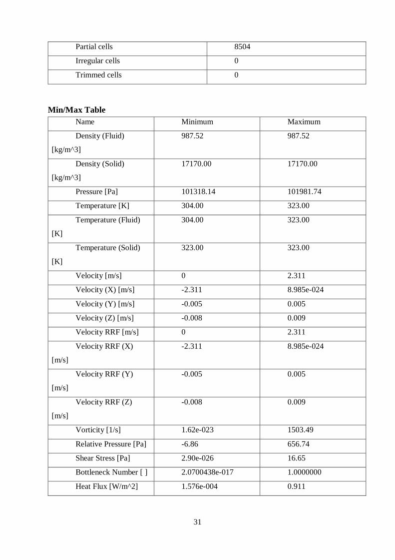
Min/Max Table
Name Minimum Maximum
Density (Fluid)
[kg/m^3]
987.52 987.52
Density (Solid)
[kg/m^3]
17170.00 17170.00
Pressure [Pa] 101318.14 101981.74
Temperature [K] 304.00 323.00
Temperature (Fluid)
[K]
304.00 323.00
Temperature (Solid)
[K]
323.00 323.00
Velocity [m/s] 0 2.311
Velocity (X) [m/s] -2.311 8.985e-024
Velocity (Y) [m/s] -0.005 0.005
Velocity (Z) [m/s] -0.008 0.009
Velocity RRF [m/s] 0 2.311
Velocity RRF (X)
[m/s]
-2.311 8.985e-024
Velocity RRF (Y)
[m/s]
-0.005 0.005
Velocity RRF (Z)
[m/s]
-0.008 0.009
Vorticity [1/s] 1.62e-023 1503.49
Relative Pressure [Pa] -6.86 656.74
Shear Stress [Pa] 2.90e-026 16.65
Bottleneck Number [ ] 2.0700438e-017 1.0000000
Heat Flux [W/m^2] 1.576e-004 0.911
32
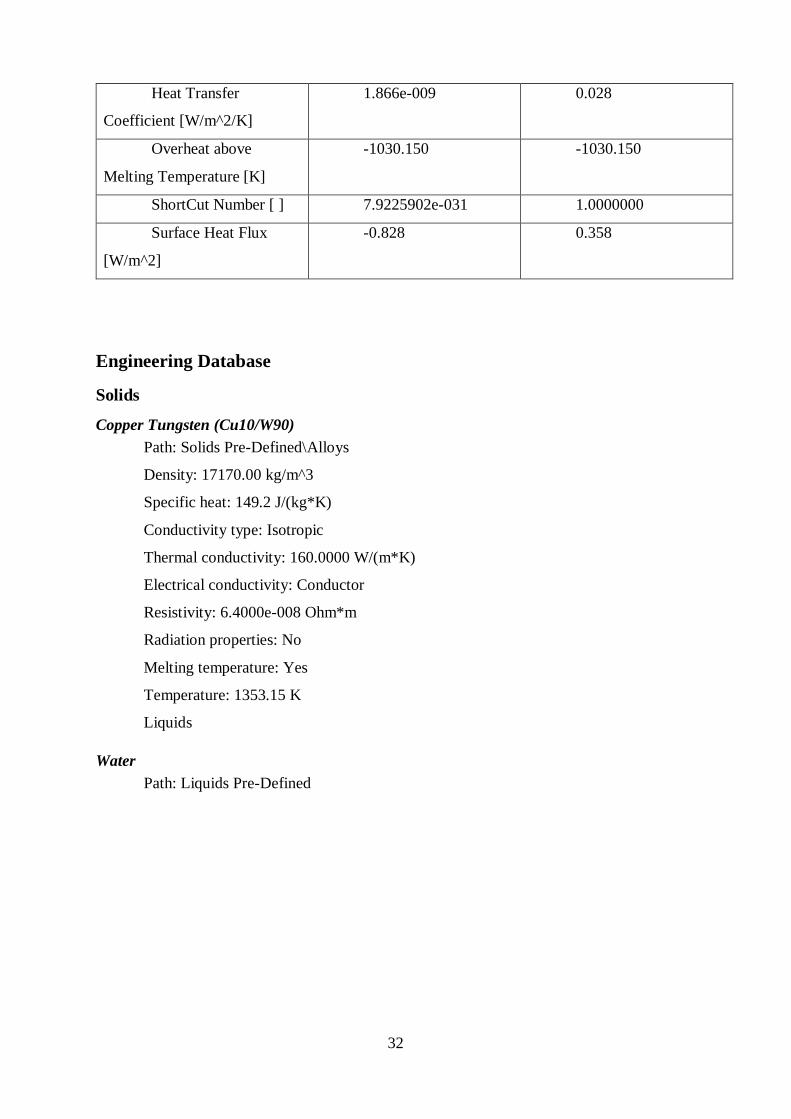
Heat Transfer
Coefficient [W/m^2/K]
1.866e-009 0.028
Overheat above
Melting Temperature [K]
-1030.150 -1030.150
ShortCut Number [ ] 7.9225902e-031 1.0000000
Surface Heat Flux
[W/m^2]
-0.828 0.358
Engineering Database
Solids
Copper Tungsten (Cu10/W90)
Path: Solids Pre-Defined\Alloys
Density: 17170.00 kg/m^3
Specific heat: 149.2 J/(kg*K)
Conductivity type: Isotropic
Thermal conductivity: 160.0000 W/(m*K)
Electrical conductivity: Conductor
Resistivity: 6.4000e-008 Ohm*m
Radiation properties: No
Melting temperature: Yes
Temperature: 1353.15 K
Liquids
Water
Path: Liquids Pre-Defined

33
Density
Dynamic viscosity
Specific heat (Cp)
Thermal conductivity
0
200
400
600
800
1000
1200
0 100 200 300 400 500 600
Den
sity
[kg/
m^3
]
Temperature[K]
0
0.0005
0.001
0.0015
0.002
0 100 200 300 400 500 600
Dyn
amic
vis
cosi
ty[P
a*s
]
Temperature[K]
0
0.1
0.2
0.3
0.4
0.5
0.6
0.7
0.8
0 100 200 300 400 500 600
The
rmal
co
nd
uct
ivit
y[W
/(m
*K)]
Temperature[K]
4100
4200
4300
4400
4500
4600
4700
4800
4900
0 100 200 300 400 500 600
Spe
cifi
c h
eat
(Cp
)[J/
(kg*
K)]
Temperature[K]

34
Cavitation effect: Yes
Temperature: 0 K
Saturation pressure: 0 Pa
Radiation properties: No
3.4 Calculations
𝑇1= Temperature of entering hot fluid
𝑇2= Temperature of leaving hot fluid
𝑇3= Temperature of entering cold fluid
𝑇4= Temperature of leaving hot fluid
For parallel flow,
∆𝑇1=𝑇1-𝑇3
∆𝑇1= 49.6℃-29.3℃
= 20.3℃
∆𝑇2=𝑇2-𝑇4
∆𝑇2=48.5℃-29.9℃
=18.6℃
∆𝑇𝑙𝑚=∆𝑇1−∆𝑇2
𝑙𝑛∆𝑇1∆𝑇2
∆𝑇𝑙𝑚=20.3−18.6
𝑙𝑛20.3
18.6
= 19.43
Figure 22: Parallel flow

35
𝑄𝑒= Heat emitted from hot fluid
𝑄𝑎= Heat absorb from cold fluid
�̇�ℎ=Mass flow rate of hot fluid
�̇�𝑐=Mass flow rate of cold fluid
𝑐ℎ= Specific heat of hot fluid
𝑐𝑐= specific heat of cold fluid
𝑄𝑒= �̇�ℎ𝑐ℎ(𝑇ℎ,1 − 𝑇ℎ,2)
𝑄𝑎= �̇�ℎ(𝑇𝑐,1 − 𝑇𝑐,2)
𝑄𝑒=16.22*10−6*(49.6-48.5) *4134
=73.75W
𝑄𝑒=UA∆𝑇𝑙𝑚
A=outer surface of copper tube
A=2𝜋𝑅𝑜L
U=𝑄𝑒
𝐴∆𝑇𝑙𝑚
A=2*3.14*0.005*0.5𝑚2
=0.0157𝑚2
U=73.75
0.0157∗19.43
=241.76W/𝑚2𝑘
Experiential valve for cupper and water is 241.76W/𝑚2𝑘
Theoretical value range for cupper and water is 240-455 W/𝑚2𝑘
3.5 Future works
We have planned to do some future actives to conduct in near future. These activities will
help us to give a precious output with all functions. Our future plans mention as bellows.
Modify this apparatus to get both parallel & counter flow.
Insulate heat exchanger part to reduce losses.
Suppose to attach shell & tube and plate heat exchanger to this apparatus.

36
Figure 23: time Line
3.6 Time Line

37
BIBLIOGRAPHY
[1] A. Ltd, “Computer Controlled Heat Exchanger Service Module,” Armfield Ltd, 2016.
[Online]. Available: http://discoverarmfield.com/en/products/view/ht30xc/computer-
controlled-heat-exchanger-service-module. (May 2016)
[2] M. S. BIN ALIAS, “DESIGN OF SMALL HEAT EXCHANGER,” 2010.
[3] D. P. F. P. I. A. S. L. DeWitt, willey, 7th ed. wiley, 2011.

38
APPENDIX
DEPARTMENT OF MECHANICAL AND MANUFACTURING ENGINEERING
M3 – THERMODYNAMIC LABORATORY
MEXXXX: HEAT TRANSFER
Lab sheet
DATE :
TITLE : OVERALL HEAT TRANSFER COEFFICIENT
AIM :
NOTATIONS:
Symbol
To evaluate the performance of a Heat Exchanger in
counter flow under variations of flow rates
Description Units
U Overall heat transfer coefficient [kW/𝑚2K]
A Hot water tube surface area [𝑚2]
�̇�ℎ Mass flow rate of hot water [kg/s]
𝐶ℎ Specific heat of hot water [J/kg K]
𝑇1 Cold water inlet Temperature [K]
𝑇2 Cold water outlet Temperature [K]
𝑇3 Hot water inlet Temperature [K]
𝑇4 Hot water outlet Temperature [K]
𝑇5 Hot water reservoir tank Temp. [K]
∆𝑇1 , ∆𝑇2 Temperature difference [K]
𝑄ℎ Heat emitted by cold water [K]
∆𝑇𝑙𝑚 LMTD value [K]
THEORY:
Applying the First Law of Thermodynamics, to the hot water side,
𝑄ℎ = �̇�ℎ (𝑇3 − 𝑇4)

39
According to Logarithmic Mean Temperature Difference (LMTD) method,
𝑄ℎ = 𝑈 𝐴 ∆𝑇𝑙𝑚
𝑈 = 𝑄ℎ
𝐴 ∆𝑇𝑙𝑚
∆𝑇𝑙𝑚 = ∆𝑇1− ∆𝑇2
ln (∆𝑇1∆𝑇2
)
PROCEDURE:
Open drain valve for the heat exchanger apparatus (Cold water outlet).
Closed the drain valve for hot water reservoir.
Make sure the hot water reservoir is primed (full).
Make sure the hot water reservoir is full. And also connect the clear pipe of cold water
reservoir to tap water line.
Turn on the power to heat exchanger apparatus.
Turn on the computer, login and open "Overall Heat Transfer Coefficient" folder. And
also open LabVIEW software interface
Turn on the power to the heater & set the temperature controller to 80 ℃. And check the
T5 value by using interface.
Turn on the hot water supply pump at minimum flow rate.
Once T5 sensor value is 50 ℃, turn on the cooling water supply pump.
Changing following flow rates of hot water supply, take the temperature sensor readings.
OBSERVATIONS:
1 50 4.95 27 27.6 48 47.2 48.2
2 100 7.06 27 27.8 48.3 47.6 48.6
3 150 8.7 27.1 27.9 48.9 47.9 49.1
4 200 11.07 27.3 28.3 49.1 48.2 49.7
5 250 16.22 27 28.5 50.1 48.6 50.5
Test PWM Value MASS FLOW
RATE(kg/s)( )
Temperature (C)
𝑇1 𝑇2 𝑇3 𝑇4 𝑇510−3

40
DATA:
Diameter of copper tube = 0.01m
Length of copper tube = 0.50m
CALCULATIONS:
Find the overall heat transfer coefficient for Copper and Water.
RESULTS:
Write the results you obtained.
DISCUSSION:
Write a discussion describing the following points.
1. Practical importance of the experiment.
2. State the assumptions you made during the practical.
3. Point out the problems associated with the practical.
4. Mention the reasons for the deviation of the values you obtained from the theoretical values.
REFERENCE:
[1] “Experiment Lab Manual.” [Online]. Available:
https://web.njit.edu/~me/ME_406_Exp6_Lab_Manual.pdf. [Accessed: 19-Nov-2016].

41