computer arithmetic
TRANSCRIPT

1
Computer Arithmetic
Arithmetic instructions in digital computers manipulate data to produce results necessary for the solution
of computational problems. These instructions perform arithmetic calculations and are responsible for the
bulk of activity involved in processing data in a computer. The four basic arithmetic operations are addition,
subtraction, multiplication and division. From these four basic operations, it is possible to formulate other
arithmetic functions and solve scientific problems by means of numerical analysis methods. An arithmetic
processor is the part of a processor unit that executes arithmetic operations. An arithmetic instruction may
specify binary or decimal data, and in each case the data may be in fixed-point or floating-point form.
Fixed- point numbers may represent integers or fractions. Negative numbers may be in signed- magnitude
or signed-complement representation. The arithmetic processor is very simple if only a binary fixed-point
odd instruction is included. It would be more complicated if it includes all four arithmetic operations for
binary and decimal data in fixed-point and floating- point representation.
Addition and Subtraction
There are three ways of representing negative fixed-point binary numbers: signed-magnitude, signed-l's
complement, or signed-2's complement. Most computers use the signed-2's complement representation
when performing arithmetic operations with integers. For floating- point operations, most computers use the
signed-magnitude representation for the mantissa. In this section we develop the addition and subtraction
algorithms for data represented in signed- magnitude and again for data represented in signed-2's
complement.
Addition and Subtraction with Signed-Magnitude Data
The representation of numbers in signed-magnitude is familiar because it is used in everyday arithmetic
calculations. The procedure for adding or subtracting two signed binary numbers with paper and pencil is
simple and straight-forward. We designate the magnitude of the two numbers by A and B. When the signed
numbers are added or subtracted, we find that there are eight different conditions to consider, depending on
the sign of the numbers and the operation performed. These conditions are listed in the first column of
Table. The other columns in the table show the actual operation to be performed with the magnitude of the
numbers. The last column is needed to prevent a negative zero. In other words, when two equal numbers are
subtracted, the result should be +0 not –0.
2
The algorithms for addition and subtraction are derived from the table and can be stated as follows (the
words inside parentheses should be used for the subtraction algorithm):
Addition (subtraction) algorithm: when the signs of A and B are identical (different), add the two
magnitudes and attach the sign of A to the result. When the signs of A and B are different (identical),
compare the magnitudes and subtract the smaller number from the larger. Choose the sign of the result to
be the same as A if A > B or the complement of the sign of A if A < B. If the two magnitudes are equal,
subtract B from A and make the sign of the result positive. The two algorithms are similar except for the
sign comparison. The procedure to be followed for identical signs in the addition algorithm is the same as
for different signs in the subtraction algorithm, and vice versa.
Hardware Implementation
To implement the two arithmetic operations with hardware, it is first necessary that the two numbers be
stored in registers. Let A and B be two registers that hold the magnitudes of the numbers, and A s and B s
be two flip-flops that hold the corresponding signs. The result of the operation may be transferred to a third
register: however, a saving is achieved if the result is transferred into A and As. Thus A and As together
form an accumulator register. Consider now the hardware implementation of the algorithms above. First, a
parallel-adder is needed to perform the micro-operation A + B. Second, a comparator circuit is needed to
establish if A > B, A = B, or A < B. Third, two parallel-subtractor circuits are needed to perform the
micro- operations A - B and B - A. The sign relationship can be determined from an exclusive-OR gate with
A s and B s as inputs. This procedure requires a magnitude comparator, an adder, and two subtractors.
However, a different procedure can be found that requires less equipment. First, we know that subtraction
can be accomplished by means of complement and add. Second, the result of a comparison can be
determined from the end carry after the subtraction. Careful investigation of the alternatives reveals that the
use of 2's complement for subtraction and comparison is an efficient procedure that requires only an adder
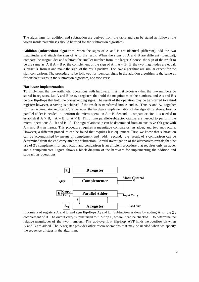
and a complementer. Figure shows a block diagram of the hardware for implementing the addition and
subtraction operations.
It consists of registers A and B and sign flip-flops As and Bs. Subtraction is done by adding A to the 2's
complement of B. The output carry is transferred to flip-flop E, where it can be checked to determine the
relative magnitudes of the two numbers. The add-overflow flip-flop AVF holds the overflow bit when
A and B are added. The A register provides other micro-operations that may be needed when we specify
the sequence of steps in the algorithm.

3
The addition of A plus B is done through the parallel adder. The S(sum) output of the adder is applied to the
input of the A register. The complementer provides an output of B or the complement of B depending on the
state of the mode control M. The complementer consists of exclusive-OR gates and the parallel adder
consists of full-adder circuits. The M signal is also applied to the input carry of the adder. When M = 0, the
output of B is transferred to the adder, the input carry is 0, and the output of the adder is equal to the sum
A+B. When M = 1, the 2’s complement of B is applied to the adder the input carry is 1, and output S = A +
B’ — 1. This is equal to A plus the 2's complement of B, which is equivalent to the subtraction A — B.
Hardware Algorithm
The flowchart for the hardware algorithm is presented in Figure. The two signs A s, and Bs are
compared by an exclusive-OR gale. If the output of the gate is 0, the signs are identical; if it is 1, the
signs are different for an add operation, identical signs dictate that the magnitudes be added.
4
For a subtract operation, different signs dictate that the magnitudes be added. The magnitudes are added
with a micro-operation EA A + B where EA is a register that combines E and A. The carry in E after
the addition constitutes an overflow if it is equal to 1 and it is transferred into the add-overflow flip-flop
AVF. The two magnitudes are subtracted if the signs are different for an add operation or identical for a
subtract operation. The magnitudes are subtracted by adding A to the 2's complement of B. No overflow
can occur if the numbers are subtracted. A 1 in E indicates that A ≥ B and the number in A is the correct
result. If this number is zero, the sign As must be made positive to avoid a –0. A 0 in E indicates that A < B.
For this case it is necessary to take the 2's complement of the value in A. This operation can be done
with one micro-operation A A’ + 1. In other paths of the flowchart, the sign of the result is the same as
the sign of A, so no change in As is required. However, when A < B, the sign of the result is the
complement of the original sign of A. It is then necessary to complement As to obtain the correct sign.
The final result is found in register A and its sign in As. The value in AVF provides an overflow
indication. The final value of E is immaterial.
Addition and Subtraction with Signed-2’s Complement Data
The signed-2's complement representation of numbers together with arithmetic algorithms for addition and
subtraction are summarized here for easy reference. The leftmost bit of a binary number represents the sign
bit: 0 for positive and 1 for negative. If the sign bit is 1, the entire number is represented in 2's complement
form. Thus +33 is represented as 00100001 and -33 as 11011111. Note that 11011111 is the 2's complement
of 00100001, and vice versa.
The addition of two numbers in signed-2's complement form consists of adding the numbers with the sign
bits treated the same as the other bits of the number. A carry-out of the sign-bit position is discarded. The
subtraction consists of first taking the 2's complement of the subtrahend and then adding it to the minuend.
When two numbers of n digits each are added and the sum occupies n + 1 digits, we say that an overflow
occurred. An overflow can be detected by inspecting the last two carries out of the addition. When the
two carries are applied to an exclusive-OR gate, the overflow is detected when the output of the gate is
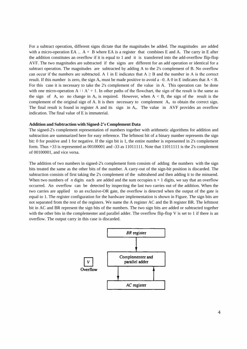
equal to 1. The register configuration for the hardware implementation is shown in Figure. The sign bits are
not separated from the rest of the registers. We name the A register AC and the B register BR. The leftmost
bit in AC and BR represent the sign bits of the numbers. The two sign bits are added or subtracted together
with the other bits in the complementer and parallel adder. The overflow flip-flop V is set to 1 if there is an
overflow. The output carry in this case is discarded.

5
The algorithm for adding and subtracting two binary numbers in signed-2's complement representation is
shown in the flowchart of Figure. The sum is obtained by adding the contents of AC and BR (including
their sign bits). The overflow bit V is set to 1 if the exclusive-OR of the last two carries is 1, and it is
cleared to 0 otherwise. The subtraction operation is accomplished by adding the content of AC to the 2's
complement of BR. Taking the 2's complement of BR has the effect of changing a positive number to
negative, and vice versa. An overflow must be checked during this operation because the two numbers
added could have the same sign. The programmer must realize that if an overflow occurs, there will be an
erroneous result in the AC register.
Comparing this algorithm with its signed-magnitude counterpart, we note that it is much simpler to add
and subtract numbers if negative numbers are maintained in signed-2's complement representation. For this
reason most computers adopt this representation over the more familiar signed-magnitude.
Multiplication Algorithm
Multiplication of two fixed-point binary numbers in signed-magnitude representation is done with
paper and pencil by a process of successive shift and add operations. This process is best illustrated
with a numerical example.

6
The process consists of looking at successive bits of the multiplier, least significant bit first. If the
multiplier bit is a 1, the multiplicand is copied down; otherwise, zeros are copied down. The numbers
copied down in successive lines are shifted one position to the left from the previous number. Finally,
the numbers are added and their sum forms the product. The sign of the product is determined from the
signs of the multiplicand and multiplier. If they are alike, the sign of the product is positive. If they are
unlike, the sign of the product is negative.
Hardware Implementation for Signed-Magnitude Data
When multiplication is implemented in a digital computer, it is convenient to change the process
slightly. First, instead of providing registers to store and add simultaneously as many binary numbers
as there are bits in the multiplier, it is convenient to provide an adder for the summation of only two
binary numbers and successively accumulate the partial products in a register. Second, instead of
shifting the multiplicand to the left, the partial product is shifted to the right, which results in leaving
the partial product and the multiplicand in the required relative positions. Third, when the
corresponding bit of the multiplier is 0, there is no need to add all zeros to the partial product since it
will not alter its value. The hardware for multiplication consists of the equipment shown in Figure. The
multiplier is stored in the Q register and its sign in Qs. The sequence counter SC is initially set to a
number equal to the number of bits in the multiplier. The counter is decremented by 1 after forming
each partial product. When the content of the counter reaches zero, the product is formed and the
process stops.
Initially, the multiplicand is in register B and the multiplier in Q. The sum of A and B forms a partial
product which is transferred to the EA register. Both partial product and multiplier are shifted to the
right. This shift will be denoted by the statement shr EAQ to designate the right shift depicted in
Figure. The least significant bit of A is shifted into the most significant position of Q, the bit from E is
shifted into the most significant position of A, and 0 is shifted into E. After the shift, one bit of the
partial product is shifted into Q, pushing the multiplier bits one position to the right. In this manner, the
rightmost flip-flop in register Q, designated by Q„, will hold the bit of the multiplier, which must be
inspected next.

7
Hardware Algorithm
Figure shows a flowchart of the hardware multiply algorithm. Initially, the multiplicand is in B and the
multiplier in Q. Their corresponding signs are in Bs and Qs, respectively. The signs are compared, and
both A and Q are set to correspond to the sign of the product since a double- length product will be
stored in registers A and Q. Registers A and E are cleared and the sequence counter SC is set to a
number equal to the number of bits of the multiplier. We are assuming here that operands are
transferred to registers from a memory unit that has words of n bits. Since an operand must be stored
with its sign, one bit of the word will be occupied by the sign and the magnitude will consist of n — 1
bits.
After the initialization, the low-order bit of the multiplier in Qn is tested. If it is a 1, the multiplicand in B is
added to the present partial product in A. If it is a 0, nothing is done. Register EAQ is then shifted once to
the right to form the new partial product. The sequence

8
counter is decremented by 1 and its new value checked. If it is not equal to zero, the process is repeated and
a new partial product is formed. The process stops when SC = 0. Note that the partial product formed in A is
shifted into Q one bit at a time and eventually replaces the multiplier. The final product is available in both
A and Q, with A holding the most significant bits and Q holding the least significant bits. The previous
numerical example is repeated in Table is shown to clarify the hardware multiplication process. The
procedure follows the steps outlined in the flowchart.
Booth Multiplication Algorithm
Booth algorithm gives a procedure for multiplying binary integers in signed-2’s complement representation.
It operates on the fact that strings of 0's in the multiplier require no addition but just shifting, and a string of
Ts in the multiplier from bit weight 2* to weight 2 m can be treated as 2 k+1 — 2 m . For example, the
binary number 001110 (+14) has a string of 1’s from 2^k to 2^m (k = 3, m = 1). The number can be
represented as 2k+1 - 2m = 16 - 2 = 14. Therefore, the multiplication M x 14, where M is the multiplicand
and 14 the multiplier, can be done as M x 24
- M x 21. Thus the product can be obtained by shifting the binary multiplicand M four times to the left and
subtracting M shifted left once. As in all multiplication schemes. Booth algorithm requires examination of
the multiplier bits and shifting of the partial product. Prior to the shifting, the multiplicand may be added to
the partial product, subtracted from the partial product, or left unchanged according to the following rules:
1. The multiplicand is subtracted from the partial product upon encountering the first least
significant 1 in a string of 1’s in the multiplier.
2. The multiplicand is added to the partial product upon encountering the first 0 (provided that there
was a previous 1) in a string of 0's in the multiplier.
3. 3. The partial product does not change when the multiplier bit is identical to the previous
multiplier bit.
The algorithm works for positive or negative multipliers in 2's complement representation. This is because
a negative multiplier ends with a string of 1’s and the last operation will be a subtraction of the appropriate
weight. For example, a multiplier equal to -14 is represented in 2's complement as 110010 and is treated
as -2^4 + 2^2 – 2^1 = –14.

9
The hardware implementation of Booth algorithm requires the register configuration shown in Figure. We
rename registers A, B, and Q, as AC, BR, and QR, respectively. Qn designates the least significant bit of
the multiplier in register QR. An extra flip-flop Qn+1 is appended to QR to facilitate a double bit inspection
of the multiplier. The flowchart for Booth algorithm is shown in Figure. AC and the appended bit Qn+1
are initially cleared to 0 and the sequence counter SC is set to a number n equal to the number of bits in the
multiplier. The two bits of the multiplier in Qn and Qn+1 are inspected. If the two bits are equal to 10, it
means that the first 1 in a string of l's has been encountered. This requires a subtraction of the multiplicand
from the partial product in AC. If the two bits are equal to 01, it means that the first 0 in a string of 0's has
been encountered. This requires the addition of the multiplicand to the partial product in AC. When the two
bits are equal, the partial product does not change. An overflow cannot occur because the addition and
subtraction of the multiplicand follow each other. As a consequence, the two numbers that are added always
have opposite signs, a condition that excludes an overflow. The next step is to shift right the partial product
and the multiplier (including bit Qn+1). This is an arithmetic shift right (ashr) operation which shifts AC and
QR to the right and leaves the sign bit in AC unchanged. The sequence counter is decremented and the
computational loop is repeated n times.

10
A numerical example of Booth algorithm is shown in Table for n = 5. It shows the step-by-step
multiplication of (-9) x (-13) = +117. Note that the multiplier in QR is negative and that the multiplicand in
BR is also negative. The 10-bit product appears in AC and QR and is positive. The final value of Qn+1 is
the original sign bit of the multiplier and should not be taken as part of the product.
11
Division Algorithms
Division of two fixed-point binary numbers in signed-magnitude representation is done with paper and
pencil by a process of successive compare, shift, and subtract operations. Binary division is simpler
than decimal division because the quotient digits are either 0 or 1 and there is no need to estimate how
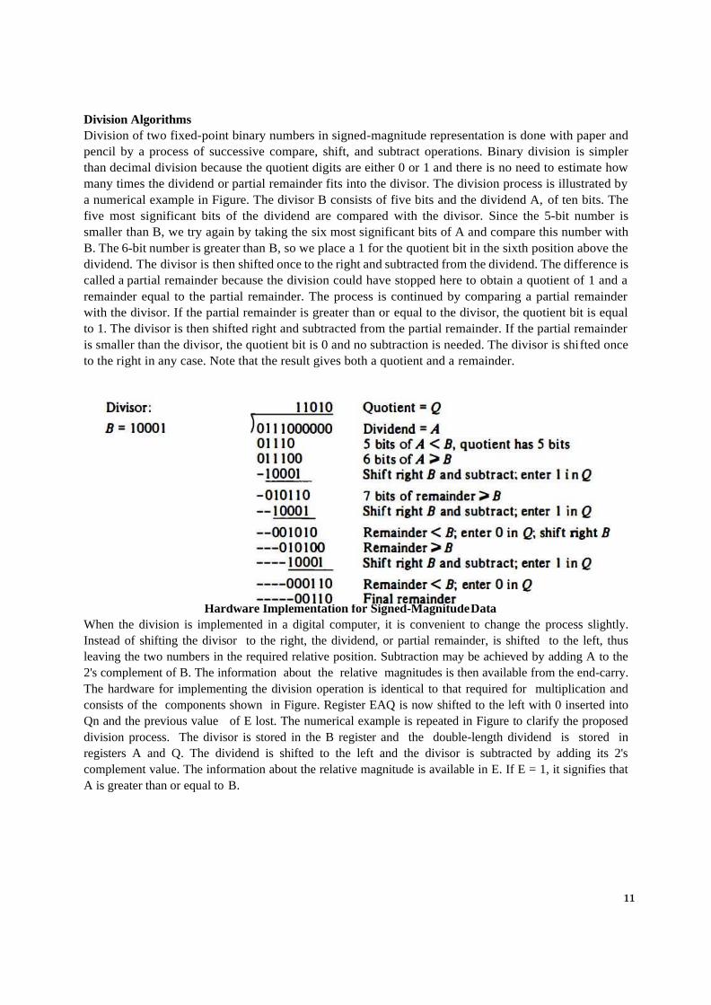
many times the dividend or partial remainder fits into the divisor. The division process is illustrated by
a numerical example in Figure. The divisor B consists of five bits and the dividend A, of ten bits. The
five most significant bits of the dividend are compared with the divisor. Since the 5-bit number is
smaller than B, we try again by taking the six most significant bits of A and compare this number with
B. The 6-bit number is greater than B, so we place a 1 for the quotient bit in the sixth position above the
dividend. The divisor is then shifted once to the right and subtracted from the dividend. The difference is
called a partial remainder because the division could have stopped here to obtain a quotient of 1 and a
remainder equal to the partial remainder. The process is continued by comparing a partial remainder
with the divisor. If the partial remainder is greater than or equal to the divisor, the quotient bit is equal
to 1. The divisor is then shifted right and subtracted from the partial remainder. If the partial remainder
is smaller than the divisor, the quotient bit is 0 and no subtraction is needed. The divisor is shifted once
to the right in any case. Note that the result gives both a quotient and a remainder.
Hardware Implementation for Signed-Magnitude Data
When the division is implemented in a digital computer, it is convenient to change the process slightly.
Instead of shifting the divisor to the right, the dividend, or partial remainder, is shifted to the left, thus
leaving the two numbers in the required relative position. Subtraction may be achieved by adding A to the
2's complement of B. The information about the relative magnitudes is then available from the end-carry.
The hardware for implementing the division operation is identical to that required for multiplication and
consists of the components shown in Figure. Register EAQ is now shifted to the left with 0 inserted into
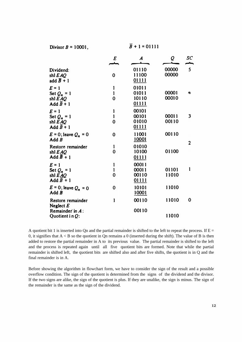
Qn and the previous value of E lost. The numerical example is repeated in Figure to clarify the proposed
division process. The divisor is stored in the B register and the double-length dividend is stored in
registers A and Q. The dividend is shifted to the left and the divisor is subtracted by adding its 2's
complement value. The information about the relative magnitude is available in E. If E = 1, it signifies that
A is greater than or equal to B.
12
A quotient bit 1 is inserted into Qn and the partial remainder is shifted to the left to repeat the process. If E =
0, it signifies that A < B so the quotient in Qn remains a 0 (inserted during the shift). The value of B is then
added to restore the partial remainder in A to its previous value. The partial remainder is shifted to the left
and the process is repeated again until all five quotient bits are formed. Note that while the partial
remainder is shifted left, the quotient bits are shifted also and after five shifts, the quotient is in Q and the
final remainder is in A.
Before showing the algorithm in flowchart form, we have to consider the sign of the result and a possible
overflow condition. The sign of the quotient is determined from the signs of the dividend and the divisor.
If the two signs are alike, the sign of the quotient is plus. If they are unalike, the sign is minus. The sign of
the remainder is the same as the sign of the dividend.

13
Divide Overflow
The division operation may result in a quotient with an overflow. This is not a problem when working
with paper and pencil but is critical when the operation is implemented with hardware. This is because
the length of registers is finite and will not hold a number that exceeds the standard length. To see this,
consider a system that has 5-bit registers. We use one register to hold the divisor and two registers to
hold the dividend. From the example of Figure we note that the quotient will consist of six bits if the
five most significant bits of the dividend constitute a number greater than the divisor. The quotient is to
be stored in a standard 5-bit register, so the overflow bit will require one more flip-flop for storing the
sixth bit. This divide- overflow condition must be avoided in normal computer operations because the
entire quotient will be too long for transfer into a memory unit that has words of standard length, that
is, the same as the length of registers. Provisions to ensure that this condition is detected must be
included in either the hardware or the software of the computer, or in a combination of the two.
When the dividend is twice as long as the divisor, the condition for overflow can be stated as follows:
A divide-overflow condition occurs if the high-order half bits of the dividend constitute a number
greater than or equal to the divisor. Another problem associated with division is the fact that a division
by zero must be avoided. The divide-overflow condition takes care of this condition as well. This
occurs because any dividend will be greater than or equal to a divisor which is equal to zero. Overflow
condition is usually detected when a special flip-flop is set. We will call it a divide-overflow flip-flop
and label it DVF.
Hardware Algorithm
The hardware divide algorithm is shown in the flowchart of Figure. The dividend is in A and Q and the
divisor in B. The sign of the result is transferred into Qs to be part of the quotient. A constant is set into the
sequence counter SC to specify the number of bits in the quotient. As in multiplication, we assume that
operands are transferred to registers from a memory unit that has words of n bits. Since an operand must
be stored with its sign, one bit of the word will be occupied by the sign and the magnitude will consist of n -
1 bits.
A divide-overflow condition is tested by subtracting the divisor in B from half of the bits of the
dividend stored in A. If A is greater than or equal to B, the divide-overflow flip-flop DVF is set and the
operation is terminated prematurely. If A < B, no divide overflow occurs so the value of the dividend is
restored by adding B to A. The division of the magnitudes starts by shifting the dividend in AQ to the
left with the high-order bit shifted into E. If the bit shifted into E is 1, we know that EA > B because
EA consists of a 1 followed by n-l bits while B consists of only n-1 bits. In this case, B must be
subtracted from EA and 1 inserted into Qn for the quotient bit. Since register A is missing the high-order
bit of the dividend (which is in E), its value is EA – 2n-1. Adding to this value the 2's complement of B
results in (EA – 2n-1) + (2n-1 - B) = EA - B The carry from this addition is not transferred to E if we want
E to remain a 1.
If the shift-left operation inserts a 0 into E, the divisor is subtracted by adding its 2's complement value
and the carry is transferred into E. If E = 1, it signifies that A greater than or equal to B; therefore, Qn is set
to 1. If E = 0, it signifies that A < B and the original number is restored by adding B to A. In the latter case
we leave a 0 in Qn (0 was inserted during the shift).

14
This process is repeated again with register A holding the partial remainder. After n-l times, the quotient
magnitude is formed in register Q and the remainder is found in register A. The quotient sign is in Qs and
the sign of the remainder in As is the same as the original sign of the dividend.

15
Floating-Point Arithmetic Operations
Many high-level programming languages have a facility for specifying floating-point numbers. Any
computer that has a compiler for such high-level programming language must have a provision for handling
floating-point arithmetic operations. The operations are quite often included in the internal hardware. If no
hardware is available for the operations, the compiler must be designed with a package of floating-point
software subroutines. Although the hardware method is more expensive, it is so much more efficient than
the software method that floating-point hardware is included in4nost computers and is omitted only in
very small ones.
A floating-point number in computer registers consists of two parts: a mantissa m and an exponent e. The
two parts represent a number obtained from multiplying m times a radix r raised to the value of e ; thus m
x re. The mantissa may be a fraction or an integer. The location of the radix point and the value of the
radix r are assumed and are not included in the registers. For example, assume a fraction representation and
a radix 10. The decimal number 537.25 is represented in a register with m = 53725 and e = 3 and is
interpreted to represent the floating- point number 0.53725 x 10^3. A floating-point number is normalized if
the most significant digit of the mantissa is nonzero. In this way the mantissa contains the maximum
possible number of significant digits. A zero cannot be normalized because it does not have a nonzero digit.
It is represented in floating-point by all 0's in the mantissa and exponent.
Arithmetic operations with floating-point numbers are more complicated than with fixed-point numbers and
their execution takes longer and requires more complex hardware. Adding or subtracting two numbers
requires first an alignment of the radix point since the exponent parts must be made equal before adding or
subtracting the mantissas. The alignment is done by shifting one mantissa while its exponent is adjusted
until it is equal to the other exponent. Consider the sum of the following floating-point numbers:
It is necessary that the two exponents be equal before the mantissas can be added. We can either shift the
first number three positions to the left, or shift the second number three positions to the right. When the
mantissas are stored in registers, shifting to the left causes a loss of most significant digits. Shifting to the
right causes a loss of least significant digits. The second method is preferable because it only reduces the
accuracy, while the first method may cause an error. The usual alignment procedure is to shift the
mantissa that has the smaller exponent to the right by a number of places equal to the difference between the
exponents. After this is done, the mantissas can be added:
When two normalized mantissas are added, the sum may contain an overflow digit. An overflow can be
corrected easily by shifting the sum once to the right and incrementing the exponent. When two numbers are
subtracted, the result may contain most significant zeros as shown in the following example:
16
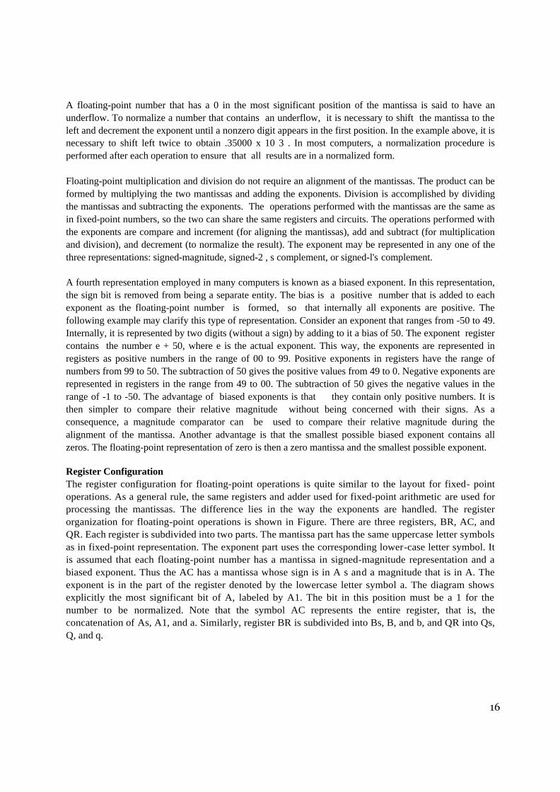
A floating-point number that has a 0 in the most significant position of the mantissa is said to have an
underflow. To normalize a number that contains an underflow, it is necessary to shift the mantissa to the
left and decrement the exponent until a nonzero digit appears in the first position. In the example above, it is
necessary to shift left twice to obtain .35000 x 10 3 . In most computers, a normalization procedure is
performed after each operation to ensure that all results are in a normalized form.
Floating-point multiplication and division do not require an alignment of the mantissas. The product can be
formed by multiplying the two mantissas and adding the exponents. Division is accomplished by dividing
the mantissas and subtracting the exponents. The operations performed with the mantissas are the same as
in fixed-point numbers, so the two can share the same registers and circuits. The operations performed with
the exponents are compare and increment (for aligning the mantissas), add and subtract (for multiplication
and division), and decrement (to normalize the result). The exponent may be represented in any one of the
three representations: signed-magnitude, signed-2 , s complement, or signed-l's complement.
A fourth representation employed in many computers is known as a biased exponent. In this representation,
the sign bit is removed from being a separate entity. The bias is a positive number that is added to each
exponent as the floating-point number is formed, so that internally all exponents are positive. The
following example may clarify this type of representation. Consider an exponent that ranges from -50 to 49.
Internally, it is represented by two digits (without a sign) by adding to it a bias of 50. The exponent register
contains the number e + 50, where e is the actual exponent. This way, the exponents are represented in
registers as positive numbers in the range of 00 to 99. Positive exponents in registers have the range of
numbers from 99 to 50. The subtraction of 50 gives the positive values from 49 to 0. Negative exponents are
represented in registers in the range from 49 to 00. The subtraction of 50 gives the negative values in the
range of -1 to -50. The advantage of biased exponents is that they contain only positive numbers. It is
then simpler to compare their relative magnitude without being concerned with their signs. As a
consequence, a magnitude comparator can be used to compare their relative magnitude during the
alignment of the mantissa. Another advantage is that the smallest possible biased exponent contains all
zeros. The floating-point representation of zero is then a zero mantissa and the smallest possible exponent.
Register Configuration
The register configuration for floating-point operations is quite similar to the layout for fixed- point
operations. As a general rule, the same registers and adder used for fixed-point arithmetic are used for
processing the mantissas. The difference lies in the way the exponents are handled. The register
organization for floating-point operations is shown in Figure. There are three registers, BR, AC, and
QR. Each register is subdivided into two parts. The mantissa part has the same uppercase letter symbols
as in fixed-point representation. The exponent part uses the corresponding lower-case letter symbol. It
is assumed that each floating-point number has a mantissa in signed-magnitude representation and a
biased exponent. Thus the AC has a mantissa whose sign is in A s and a magnitude that is in A. The
exponent is in the part of the register denoted by the lowercase letter symbol a. The diagram shows
explicitly the most significant bit of A, labeled by A1. The bit in this position must be a 1 for the
number to be normalized. Note that the symbol AC represents the entire register, that is, the
concatenation of As, A1, and a. Similarly, register BR is subdivided into Bs, B, and b, and QR into Qs,
Q, and q.

17
A parallel-adder adds the two mantissas and transfers the sum into A and the carry into E. A separate
parallel-adder is used for the exponents. Since the exponents are biased, they do not have a distinct sign bit
but are represented as a biased positive quantity. It is assumed that the floating-point numbers are so large
that the chance of an exponent overflow is very remote, and for this reason the exponent overflow will be
neglected. The exponents are also connected to a magnitude comparator that provides three binary outputs
to indicate their relative magnitude. The number in the mantissa will be taken as a fraction, so the binary
point is assumed to reside to the left of the magnitude part. Integer representation for floating-point causes
certain scaling problems during multiplication and division. To avoid these problems, we adopt a fraction
representation. The numbers in the registers are assumed to be initially normalized. After each arithmetic
operation, the result will be normalized. Thus all floating-point operands coming from and going to the
memory unit are always normalized.
Addition and Subtraction
During addition or subtraction, the two floating-point operands are in AC and BR. The sum or difference is
formed in the AC. The algorithm can be divided into four consecutive parts:
1. Check for zeros.
2. Align the mantissas.
3. Add or subtract the mantissas.
4. Normalize the result.
A floating-point number that is zero cannot be normalized. If this number is used during the computation,
the result may also be zero. Instead of checking for zeros during the normalization process we check for
zeros at the beginning and terminate the process if necessary. The alignment of the mantissas must be
carried out prior to their operation. After the mantissas are added or subtracted, the result may be
unnormalized. The normalization procedure ensures that the result is normalized prior to its transfer to
memory.
The flowchart for adding or subtracting two floating-point binary numbers is shown in Figure. If BR is
equal to zero, the operation is terminated, with the value in the AC being the result. If AC is equal to
zero, we transfer the content of BR into AC and also complement its sign if the numbers are to be
subtracted. If neither number is equal to zero, we proceed to align the mantissas.

18

19
The magnitude comparator attached to exponents a and b provides three outputs that indicate their relative
magnitude. If the two exponents are equal, we go to perform the arithmetic operation. If the exponents are
not equal, the mantissa having the smaller exponent is shifted to the right and its exponent incremented.
This process is repeated until the two exponents are equal.
The addition and subtraction of the two mantissas is identical to the fixed-point addition and subtraction
algorithm. The magnitude part is added or subtracted depending on the operation and the signs of the two
mantissas. If an overflow occurs when the magnitudes are added, it is transferred into flip-flop E. If E is
equal to 1, the bit is transferred into A1 and all other bits of A are shifted right. The exponent must be
incremented to maintain the correct number. No underflow may occur in this case because the original
mantissa that was not shifted during the alignment was already in a normalized position. If the magnitudes
were subtracted, the result may be zero or may have an underflow. If the mantissa is zero, the entire
floating-point number in the AC is made zero. Otherwise, the mantissa must have at least one bit that is
equal to 1. The mantissa has an underflow if the most significant bit in position A1 is 0. In that case, the
mantissa is shifted left and the exponent decremented. The bit in A1 is checked again and the process is
repeated until it is equal to 1. When A1 = 1, the mantissa is normalized and the operation is completed.
Multiplication
The multiplication of two floating-point numbers requires that we multiply the mantissas and add the
exponents. No comparison of exponents or alignment of mantissas is necessary. The multiplication of the
mantissas is performed in the same way as in fixed-point to provide a double-precision product. The double-
precision answer is used in fixed-point numbers to increase the accuracy of the product. In floating-point,
the range of a single-precision mantissa combined with the exponent is usually accurate enough so that only
single-precision numbers are maintained. Thus the half most significant bits of the mantissa product and
the exponent will be taken together to form a single-precision floating-point product.
The multiplication algorithm can be subdivided into four parts:
1. Check for zeros.
2. Add the exponents.
3. Multiply the mantissas.
4. Normalize the product.
Steps 2 and 3 can be done simultaneously if separate adders are available for the mantissas and exponents.
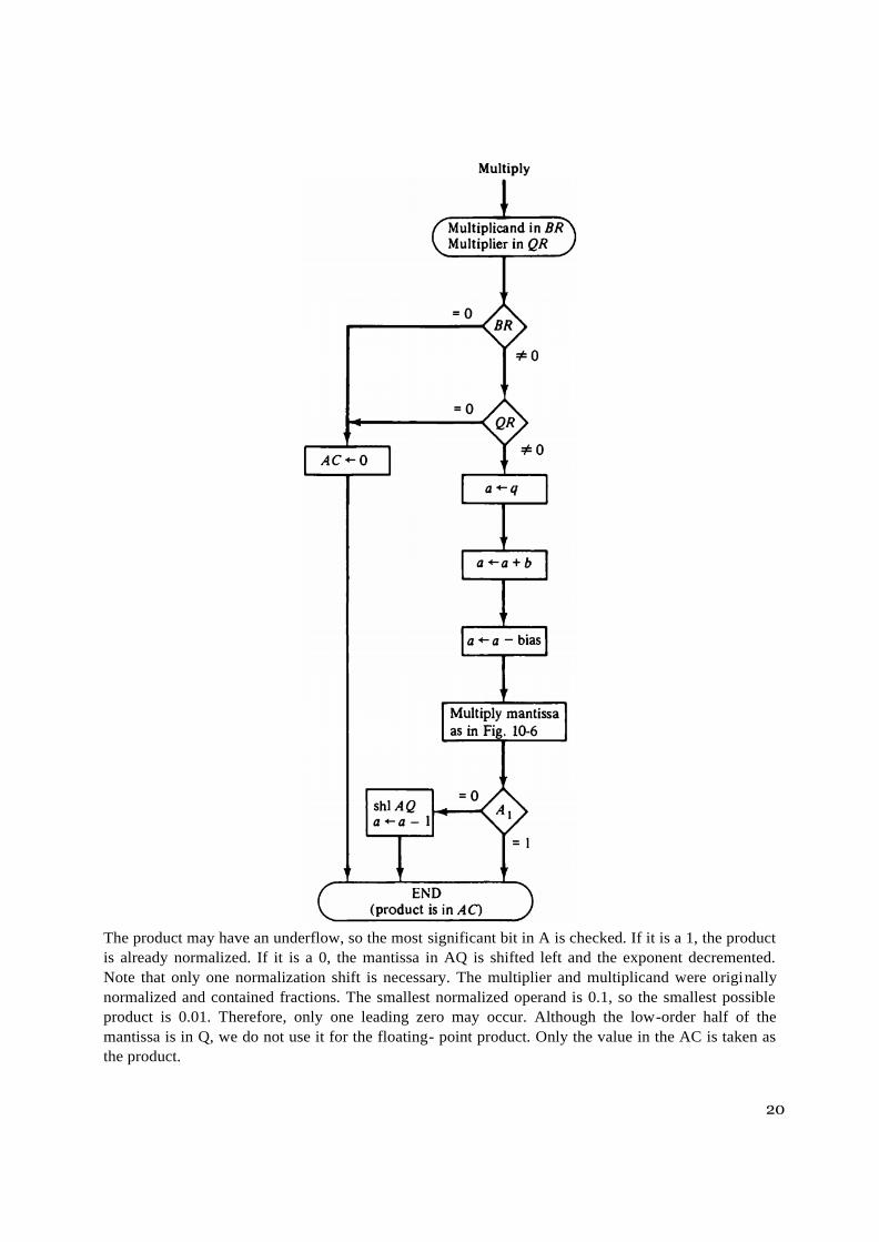
The flowchart for floating-point multiplication is shown in Figure. The two operands are checked to
determine if they contain a zero. If either operand is equal to zero, the product in the AC is set to zero and
the operation is terminated. If neither of the operands is equal to zero, the process continues with the
exponent addition. The exponent of the multiplier is in q and the adder is between exponents a and b. It is
necessary to transfer the exponents from q to a, add the two exponents, and transfer the sum into a. Since
both exponents are biased by the addition of a constant, the exponent sum will have double this bias. The
correct biased exponent for the product is obtained by subtracting the bias number from the sum. The
multiplication of the mantissas is done as in the fixed-point case with the product residing in A and Q.
Overflow cannot occur during multiplication, so there is no need to check for it.
20
The product may have an underflow, so the most significant bit in A is checked. If it is a 1, the product
is already normalized. If it is a 0, the mantissa in AQ is shifted left and the exponent decremented.
Note that only one normalization shift is necessary. The multiplier and multiplicand were originally
normalized and contained fractions. The smallest normalized operand is 0.1, so the smallest possible
product is 0.01. Therefore, only one leading zero may occur. Although the low-order half of the
mantissa is in Q, we do not use it for the floating- point product. Only the value in the AC is taken as
the product.
21
Division
Floating-point division requires that the exponents be subtracted and the mantissas divided. The mantissa
division is done as in fixed-point except that the dividend has a single-precision mantissa that is placed in
the AC. Remember that the mantissa dividend is a fraction and not an integer. For integer representation, a
single-precision dividend must be placed in register Q and register A must be cleared. The zeros in A are to
the left of the binary point and have no significance. In fraction representation, a single-precision dividend
is placed in register A and register Q is cleared. The zeros in Q are to the right of the binary point and have
no significance. The check for divide-overflow is the same as in fixed-point representation. However, with
floating-point numbers the divide-overflow imposes no problems. If the dividend is greater than or equal
to the divisor, the dividend fraction is shifted to the right and its exponent incremented by 1. For normalized
operands this is a sufficient operation to ensure that no mantissa divide-overflow will occur. The operation
above is referred to as a dividend alignment. The division of two normalized floating-point numbers will
always result in a normalized quotient provided that a dividend alignment is carried out before the division.
Therefore, unlike the other operations, the quotient obtained after the division does not require a
normalization.
The division algorithm can be subdivided into five parts:
5. Check for zeros.
6. Initialize registers and evaluate the sign.
7. Align the dividend.
8. Subtract the exponents.
9. Divide the mantissas.
The flowchart for floating-point division is shown in Figure. The two operands are checked for zero. If the
divisor is zero, it indicates an attempt to divide by zero, which is an illegal operation. The operation is
terminated with an error message. An alternative procedure would be to set the quotient in QR to the most
positive number possible (if the dividend is positive) or to the most negative possible (if the dividend is
negative). If the dividend in AC is zero, the quotient in QR is made zero and the operation terminates.
If the operands are not zero, we proceed to determine the sign of the quotient and store it in Qs. The sign
of the dividend in As is left unchanged to be the sign of the remainder. The Q register is cleared and the
sequence counter SC is set to a number equal to the number of bits in the quotient. The dividend
alignment is similar to the divide-overflow check in the fixed-point operation. The proper alignment
requires that the fraction dividend be smaller than the divisor. The two fractions are compared by a
subtraction test. The carry in E determines their relative magnitude. The dividend fraction is restored to
its original value by adding the divisor. If A is greater than or equal to B, it is necessary to shift A once
to the right and increment the dividend exponent. Since both operands are normalized, this alignment
ensures that A < B. Next, the divisor exponent is subtracted from the dividend exponent. Since both
exponents were originally biased, the subtraction operation gives the difference without the bias. The
bias is then added and the result transferred into q because the quotient is formed in QR. The
magnitudes of the mantissas are divided as in the fixed-point case. After the operation, the mantissa
quotient resides in Q and the remainder in A. The floating-point quotient is already normalized and
resides in QR.

22

23
The exponent of the remainder should be the same as the exponent of the dividend. The binary point for the
remainder mantissa lies (n—1) positions to the left of A1. The remainder can be converted to a normalized
fraction by subtracting n - 1 from the dividend exponent and by shift and decrement until the bit in A1 is
equal to 1. This is not shown in the flow chart.
Decimal Arithmetic Operations
The algorithms for arithmetic operations with decimal data are similar to the algorithms for the
corresponding operations with binary data. In fact, except for a slight modification in the multiplication and
division algorithms, the same flowcharts can be used for both types of data provided that we interpret the
micro-operation symbols properly. Decimal numbers in BCD are stored in computer registers in groups of
four bits. Each 4-bit group represents a decimal digit and must be taken as a unit when performing decimal
micro-operations. For convenience, we will use the same symbols for binary and decimal arithmetic
micro-operations but give them a different interpretation. As shown in Table, a bar over the register letter
symbol denotes the 9's complement of the decimal number stored in the register. Adding 1 to the 9's
complement produces the 10's complement.
Thus, for decimal numbers, the symbol A <- A+B’+1 denotes a transfer of the decimal sum formed by
adding the original content A to the 10's complement of B. The use of identical symbols for the 9's
complement and the l's complement may be confusing if both types of data are employed in the same system
Incrementing or decrementing a register is the same for binary and decimal except for the number of states
that the register is allowed to have. A binary counter goes through 16 states, from 0000 to 1111, when
incremented. A decimal counter goes through 10 states from 0000 to 1001 and back to 0000, since 9 is the last
count. Similarly, a binary counter sequences from 1111 to 0000 when decremented. A decimal counter goes
from 1001 to 0000. A decimal shift right or left is preceded by the letter d to indicate a shift over the four bits
that hold the decimal digits. As a numerical illustration consider a register A holding decimal 7860 in BCD.
The bit pattern of the 12 flip-flops is 0111 1000 0110 0000. The micro-operation dshr A shifts the decimal
number one digit to the right to give 0786. This shift is over the four bits and changes the content of the
register into 0000 0111 1000 0110.

24
Addition and Subtraction
The algorithm for addition and subtraction of binary signed-magnitude numbers applies also to decimal
signed-magnitude numbers provided that we interpret the micro-operation symbols in the proper
manner. Similarly, the algorithm for binary signed-2's complement numbers applies to decimal signed-
10's complement numbers. The binary data must employ a binary adder and a complementer. The
decimal data must employ a decimal arithmetic unit capable of adding two BCD numbers and forming
the 9's complement of the subtrahend. Decimal data can be added in three different ways, as shown in
Figure. The parallel method uses a decimal arithmetic unit composed of as many BCD adders as there
are digits in the number. The sum is formed in parallel and requires only one micro-operation.
In the digit-serial bit-parallel method, the digits are applied to a single BCD adder serially, while the bits
of each coded digit are transferred in parallel. The sum is formed by shifting the decimal numbers through
the BCD adder one at a time. For k decimal digits, this configuration requires k micro-operations, one for
each decimal shift. In the all serial adder, the bits are shifted one at a time through a full-adder. The binary
sum formed after four shifts must be corrected into a valid BCD digit. If the binary sum is greater than or
equal to 1010, the binary sum is corrected by adding to it 0110 and generating a carry for the next pair of
digits.

25
The parallel method is fast but requires a large number of adders. The digit-serial bit-parallel method
requires only one BCD adder, which is shared by all the digits. It is slower than the parallel method because
of the time required to shift the digits. The all serial method requires a minimum amount of equipment but
is very slow.
Multiplication
The multiplication of fixed-point decimal numbers is similar to binary except for the way the partial
products are formed. A decimal multiplier has digits that range in value from 0 to 9, whereas a binary
multiplier has only 0 and 1 digits. In the binary case, the multiplicand is added to the partial product if
the multiplier bit is 1. In the decimal case, the multiplicand must be multiplied by the digit multiplier and
the result added to the partial product. This operation can be accomplished by adding the multiplicand to
the partial product a number of times equal to the value of the multiplier digit. The registers organization
for the decimal multiplication is shown in Figure. We are assuming here four-digit numbers, with each digit
occupying four bits, for a total of 16 bits for each number. There are three registers, A, B, and Q, each
having a corresponding sign flip-flop As, Bs, and Qs.

26
27
Registers A and B have four more bits designated by Ae and Be that provide an extension of one more digit
to the registers. The BCD arithmetic unit adds the five digits in parallel and places the sum in the five-
digit A register. The end-carry goes to flip-flop E. The purpose of digit Ae is to accommodate an
overflow while adding the multiplicand to the partial product during multiplication. The purpose of digit Be
is to form the 9's complement of the divisor when subtracted from the partial remainder during the division
operation. The least significant digit in register Q is denoted by QL. This digit can be incremented or
decremented. A decimal operand coming from memory consists of 17 bits. One bit (the sign) is
transferred to Bs and the magnitude of the operand is placed in the lower 16 bits of B. Both Be and Ae are
cleared initially. The result of the operation is also 17 bits long and does not use the Ae part of the A
register. The decimal multiplication algorithm is shown in Figure. Initially, the entire A register and Be are
cleared and the sequence counter SC is set to a number k equal to the number of digits in the multiplier. The
low-order digit of the multiplier in QL is checked. If it is not equal to 0, the multiplicand in B is added to the
partial product in A once and QL is decremented. QL is checked again and the process is repeated until it
is equal to 0. In this way, the multiplicand in B is added to the partial product a number of times equal to
the multiplier digit. Any temporary overflow digit will reside in Ae and can range in value from 0 to 9.
Next, the partial product and the multiplier are shifted once to the right. This places zero in Ae and transfers
the next multiplier quotient into QL. The process is then repeated k times to form a double-length
product in AQ.
Division
Decimal division is similar to binary division except of course that the quotient digits may have any of the
10 values from 0 to 9. In the restoring division method, the divisor is subtracted from the dividend or partial
remainder as many times as necessary until a negative remainder results. The correct remainder is then
restored by adding the divisor. The digit in the quotient reflects the number of subtractions up to but
excluding the one that caused the negative difference. The decimal division algorithm is shown in Figure. It
is similar to the algorithm with binary data except for the way the quotient bits are formed. The dividend
(or partial remainder) is shifted to the left, with its most significant digit placed in Ae. The divisor is then
subtracted by adding its 10's complement value. Since Be is initially cleared, its complement value is 9 as
required. The carry in E determines the relative magnitude of A and B. If E = 0, it signifies that A < B. In
this case the divisor is added to restore the partial remainder and Q l stays at 0 (inserted there during the
shift). If E = 1, it signifies that A greater than or equal to B. The quotient digit in QL is incremented once
and the divisor subtracted again. This process is repeated until the subtraction results in a negative
difference which is recognized by E being 0. When this occurs, the quotient digit is not incremented but the
divisor is added to restore the positive remainder. In this way, the quotient digit is made equal to the number
of times that the partial remainder "goes" into the divisor. The partial remainder and the quotient bits are
shifted once to the left and the process is repeated k times to form k quotient digits. The remainder is then
found in register A and the quotient is in register Q. The value of E is neglected
