computer arithmetic, k-maps prof. sin-min lee department of computer science
TRANSCRIPT
Computer Arithmetic, K-maps
Prof. Sin-Min Lee
Department of Computer Science
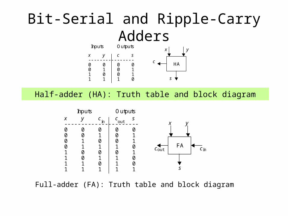
Bit-Serial and Ripple-Carry Adders
x y c s ---------------- 0 0 0 0 0 1 0 1 1 0 0 1 1 1 1 0
Inputs Outputs
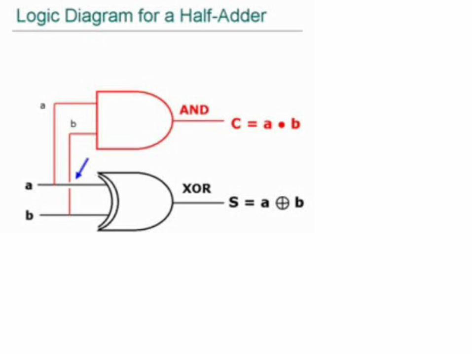
HA
x y
c
s
Half-adder (HA): Truth table and block diagram
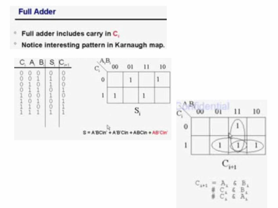
x y c c s ---------------------- 0 0 0 0 0 0 0 1 0 1 0 1 0 0 1 0 1 1 1 0 1 0 0 0 1 1 0 1 1 0 1 1 0 1 0 1 1 1 1 1
Inputs Outputs
c out c in
out in x
y
s
FA
Full-adder (FA): Truth table and block diagram
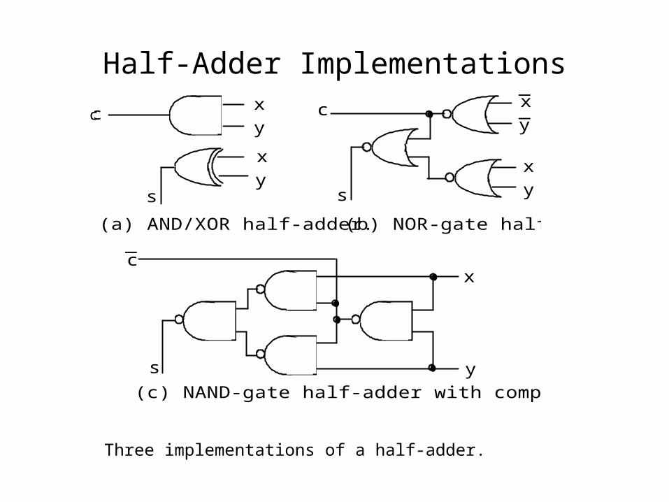
Half-Adder Implementations
c
s
(b) NOR-gate half-adder.
x
y
x
y
(c) NAND-gate half-adder with complemented carry.
x
y
c
s
s
cx
y
x
y
(a) AND/XOR half-adder._
_
_c
Three implementations of a half-adder.
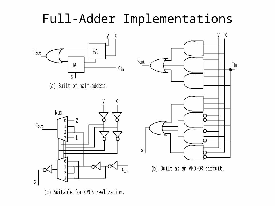
Full-Adder Implementations
HA
HA
xy
cin
cout
(a) Built of half-adders.
s
(b) Built as an AND-OR circuit.
(c) Suitable for CMOS realization.
cout
s
c in
xy
0 1 2 3
0 1 2 3
xy
c in
cout
s
0
1
Mux
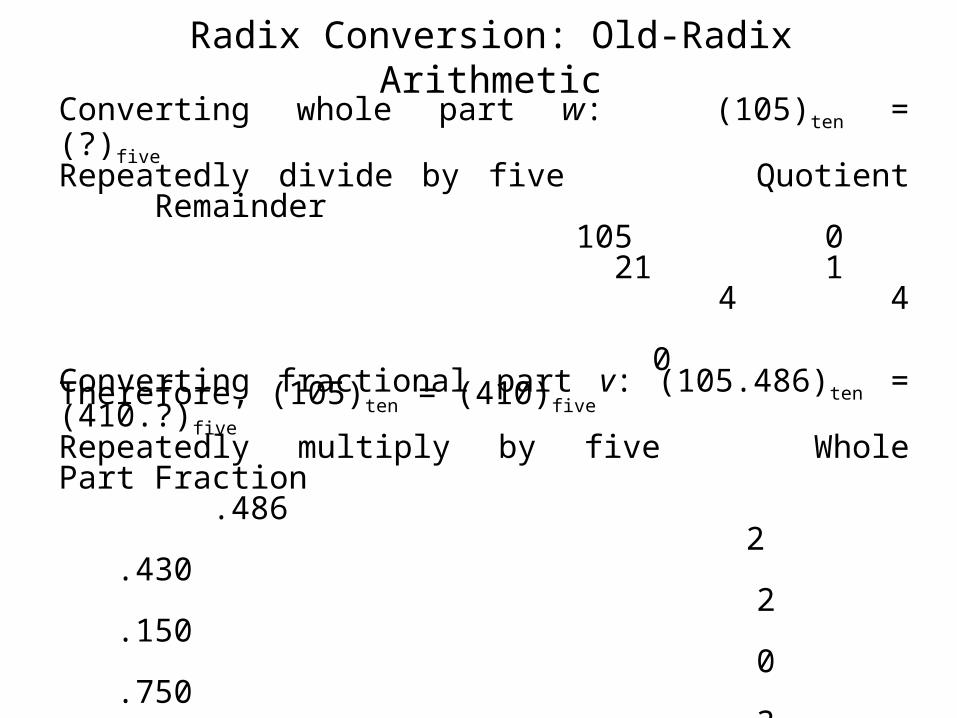
Converting whole part w: (105)ten = (?)fiveRepeatedly divide by five Quotient Remainder
105 0 21 1 4 4 0
Therefore, (105)ten = (410)five
Converting fractional part v: (105.486)ten = (410.?)fiveRepeatedly multiply by five Whole Part Fraction
.486 2 .430 2 .150 0 .750 3 .750 3 .750
Therefore, (105.486)ten (410.22033)five
Radix Conversion: Old-Radix Arithmetic
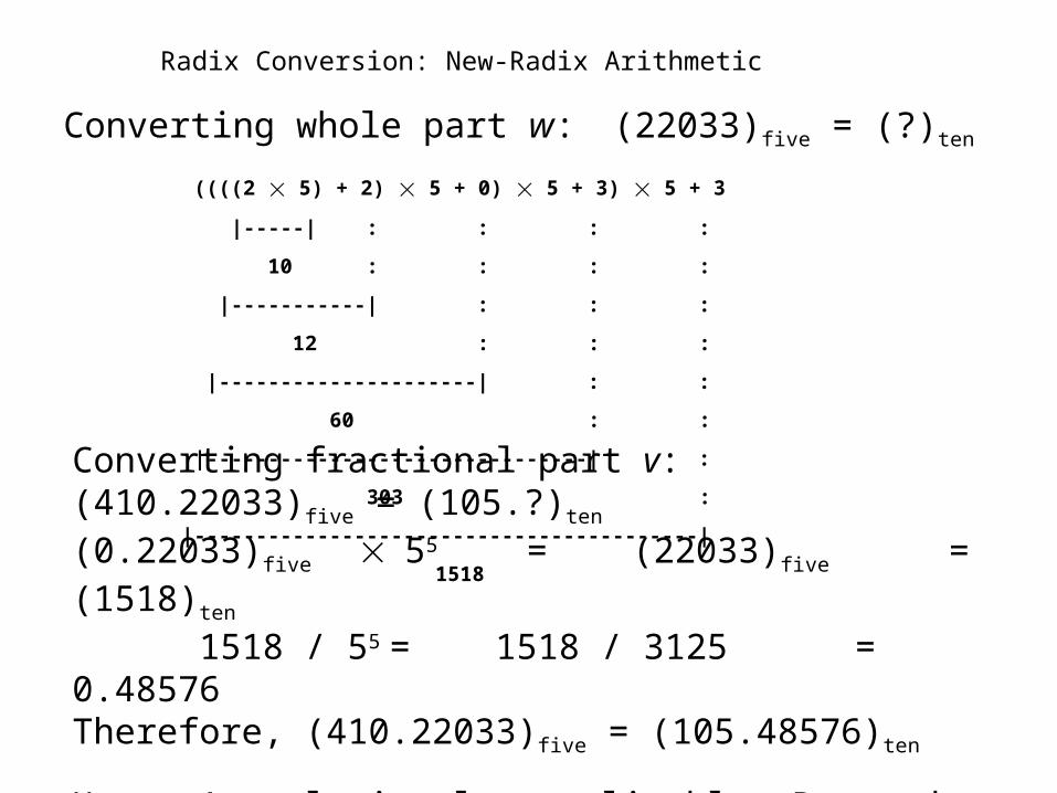
Radix Conversion: New-Radix Arithmetic
Converting whole part w: (22033)five = (?)ten
((((2 5) + 2) 5 + 0) 5 + 3) 5 + 3
|-----| : : : :
10 : : : :
|-----------| : : :
12 : : :
|---------------------| : :
60 : :
|-------------------------------| :
303 :
|-----------------------------------------|
1518
Converting fractional part v: (410.22033)five = (105.?)ten (0.22033)five 55 = (22033)five = (1518)ten
1518 / 55 = 1518 / 3125 = 0.48576Therefore, (410.22033)five = (105.48576)ten
Horner’s rule is also applicable: Proceed from right to left and use division instead of multiplication
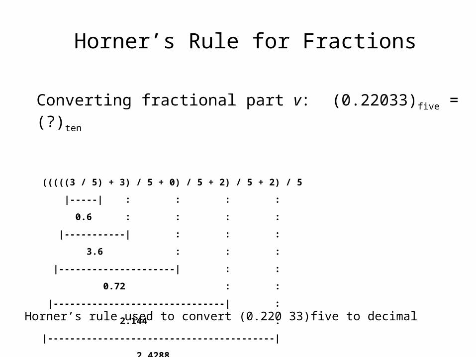
Horner’s Rule for Fractions
Converting fractional part v: (0.22033)five = (?)ten
(((((3 / 5) + 3) / 5 + 0) / 5 + 2) / 5 + 2) / 5
|-----| : : : :
0.6 : : : :
|-----------| : : :
3.6 : : :
|---------------------| : :
0.72 : :
|-------------------------------| :
2.144 :
|-----------------------------------------|
2.4288
|-----------------------------------------------|
0.48576
Horner’s rule used to convert (0.220 33)five to decimal
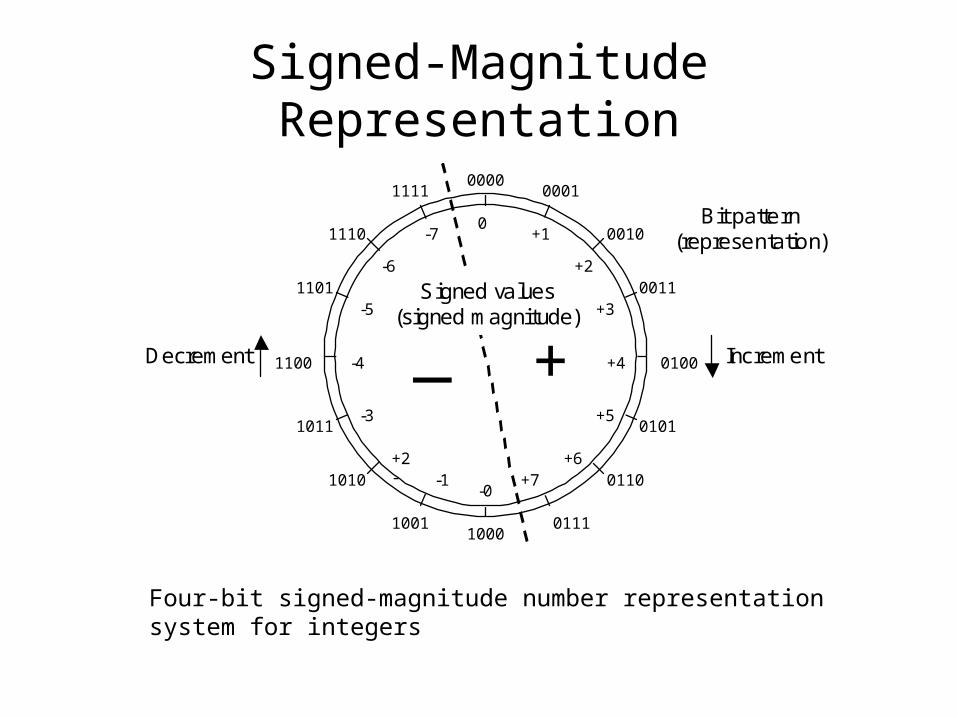
Signed-Magnitude Representation
0000 0001 1111
0010 1110
0011 1101
0100 1100
1000
0101 1011
0110 1010
0111 1001
0 +1
+3
+4
+5
+6 +7
-7
-3
-5
-4
-0 -1
+2-
+ _
Bit pattern (representation)
Signed values (signed magnitude)
+2 -6
Increment Decrement
Four-bit signed-magnitude number representation system for integers
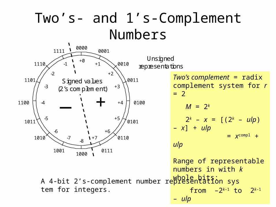
Two’s- and 1’s-Complement Numbers
0000 0001 1111
0010 1110
0011 1101
0100 1100
1000
0101 1011
0110 1010
0111 1001
+0 +1
+3
+4
+5
+6 +7
-1
-5
-3
-4
-8 -7
-6
+ _
Unsigned representations
Signed values (2’s complement)
+2 -2 Two’s complement = radix complement system for r = 2
M = 2k
2k – x = [(2k – ulp) – x] + ulp = xcompl + ulp
Range of representable numbers in with k whole bits:
from –2k–1 to 2k–1 – ulp
A 4-bit 2’s-complement number representation system for integers.
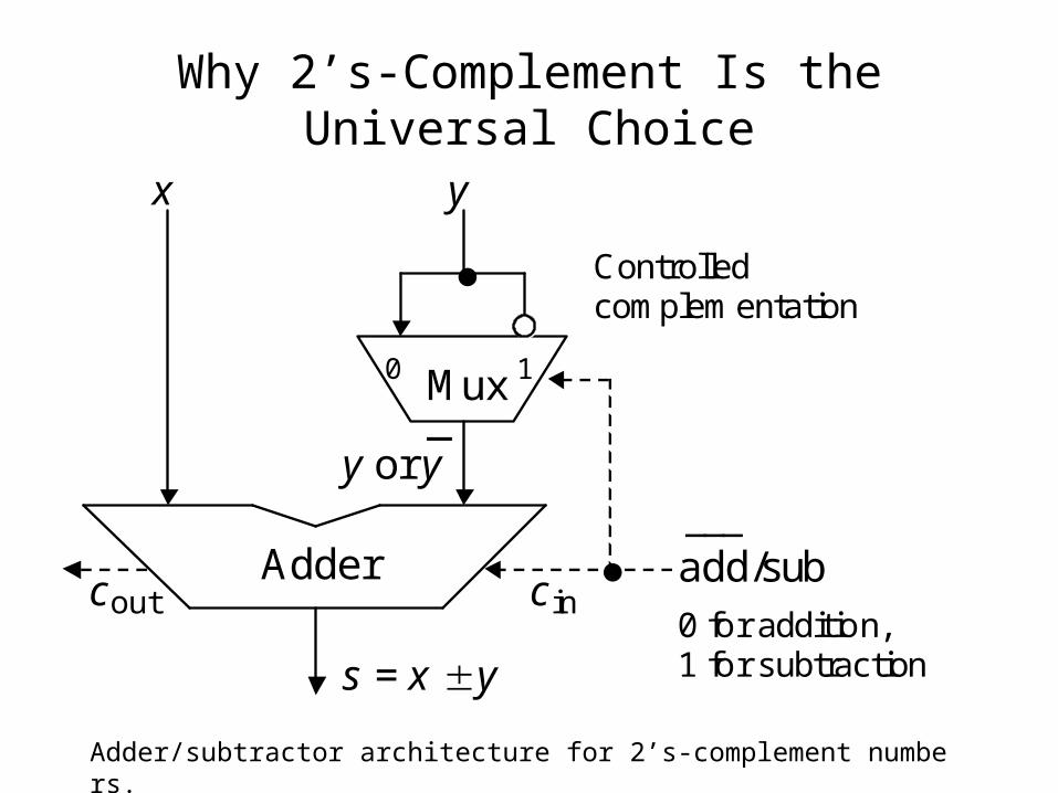
Why 2’s-Complement Is the Universal Choice
Mux
Adder
0 1
x y
y or y _
s = x y
add/sub ___
c in
Controlled complementation
0 for addition, 1 for subtraction
c out
Adder/subtractor architecture for 2’s-complement numbers.

Signed-Magnitude vs 2’s-Complement
Adder cc
s
x ySign x Sign y
Sign
Sign s
Selective Complement
Selective Complement
out in
Comp x
Control
Comp s
Add/Sub
Compl x
___ Add/Sub
Compl s
Selective complement
Selective complement
Two’s-complement adder/subtractor needs very little hardware other than a simple adder
Fig. 2.7
Mux
Adder
0 1
x y
y or y _
s = x y
add/sub ___
c in
Controlled complementation
0 for addition, 1 for subtraction
c out
Signed-magnitude adder/subtractor is significantly more complex than a simple adder
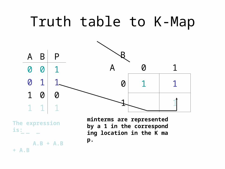
Truth table to K-Map
A B P
0 0 1
0 1 1
1 0 0
1 1 1
B
A 0 1
0 1 1
1 1
minterms are represented by a 1 in the corresponding location in the K map.
The expression is:
A.B + A.B + A.B
K-Maps
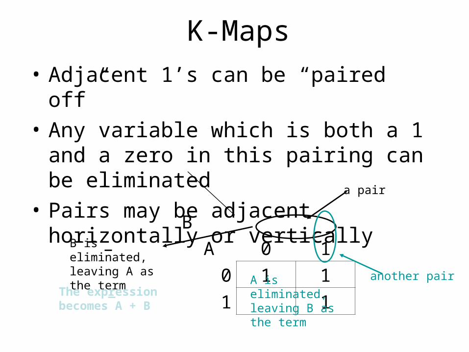
• Adjacent 1’s can be “paired off”
• Any variable which is both a 1 and a zero in this pairing can be eliminated
• Pairs may be adjacent horizontally or vertically
B
A 0 1
0 1 1
1 1
a pair
another pair
B is eliminated, leaving A as the term
A is eliminated, leaving B as the term
The expression becomes A + B
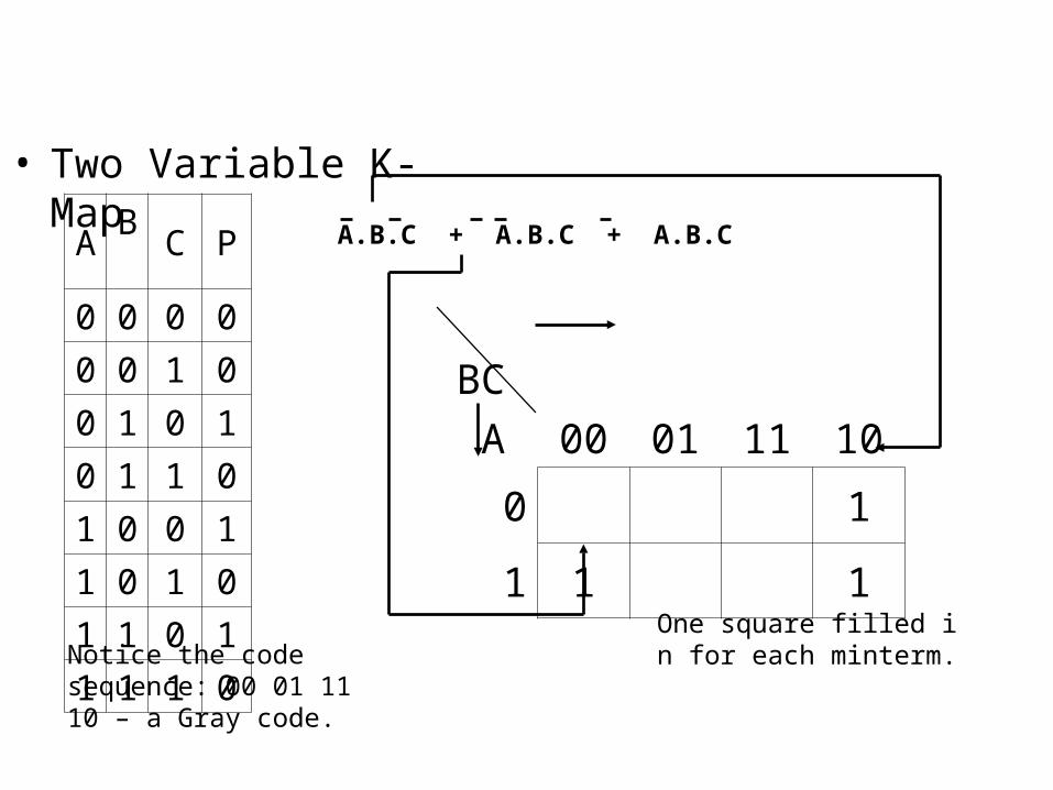
• Two Variable K-Map
AB
C P
0 0 0 0
0 0 1 0
0 1 0 1
0 1 1 0
1 0 0 1
1 0 1 0
1 1 0 1
1 1 1 0
A.B.C + A.B.C + A.B.C
BC
A 00 01 11 10
0 1
1 1 1
One square filled in for each minterm.Notice the code
sequence: 00 01 11 10 – a Gray code.
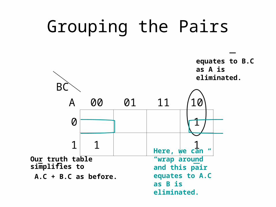
Grouping the Pairs
BC
A 00 01 11 10
0 1
1 1 1
equates to B.C as A is eliminated.
Here, we can “wrap around” and this pair equates to A.C as B is eliminated.
Our truth table simplifies to
A.C + B.C as before.
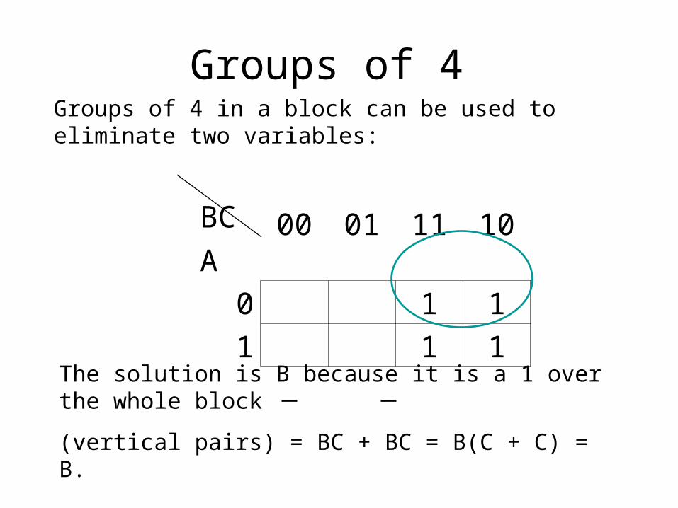
Groups of 4
BC
A00 01 11 10
0 1 1
1 1 1
Groups of 4 in a block can be used to eliminate two variables:
The solution is B because it is a 1 over the whole block
(vertical pairs) = BC + BC = B(C + C) = B.
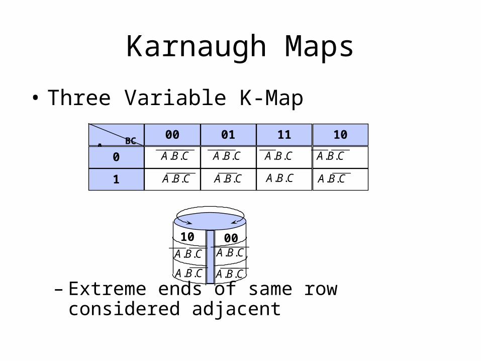
Karnaugh Maps
• Three Variable K-Map
– Extreme ends of same row considered adjacent
A BC
00 01 11 10
0
1
A.B.C A.B.C A.B.C A.B.C
A.B.C A.B.C A.B.C A.B.C
0010A.B.C
A.B.C
A.B.C
A.B.C
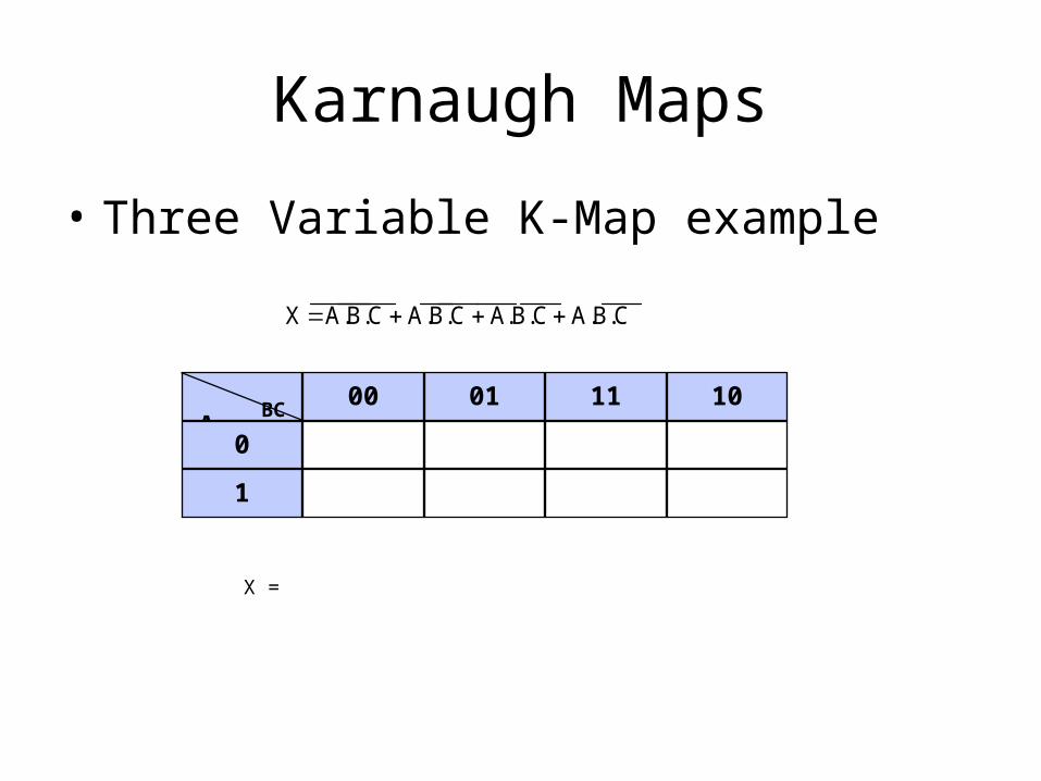
Karnaugh Maps
• Three Variable K-Map example
X A.B.C A.B.C A.B.C A.B.C
A BC
00 01 11 10
0
1
X =
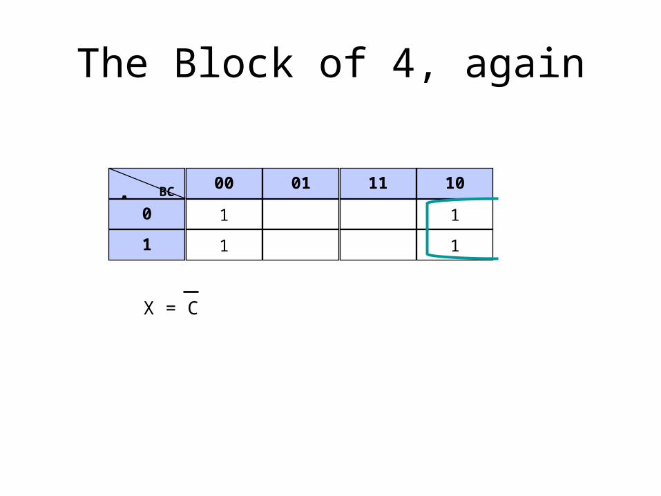
The Block of 4, again
A BC
00 01 11 10
0 1 1
1 1 1
X = C
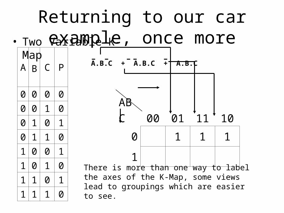
Returning to our car example, once more• Two Variable K-Map
A B
C P
0 0 0 0
0 0 1 0
0 1 0 1
0 1 1 0
1 0 0 1
1 0 1 0
1 1 0 1
1 1 1 0
A.B.C + A.B.C + A.B.C
AB
C 00 01 11 10
0 1 1 1
1
There is more than one way to label the axes of the K-Map, some views lead to groupings which are easier to see.
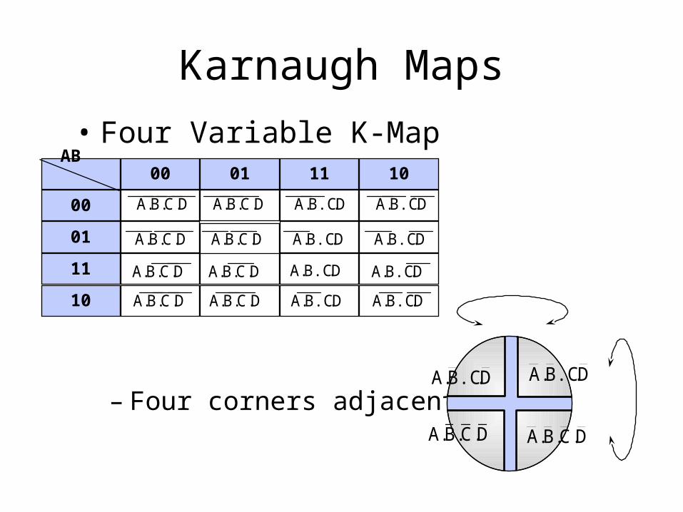
Karnaugh Maps
• Four Variable K-Map
– Four corners adjacent
AB CD
00 01 11 10
00
01
11
10
A.B.C.D A.B.C.D A.B.C.D A.B.C.D
A.B.C.D A.B.C.D A.B.C.D A.B.C.D
A.B.C.D A.B.C.D A.B.C.D A.B.C.D
A.B.C.D A.B.C.D A.B.C.D A.B.C.D
A.B.C.D
A.B.C.D
A.B.C.D
A.B.C.D
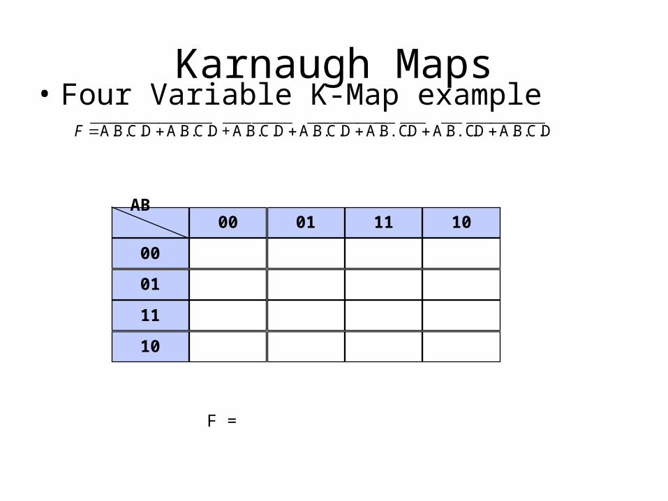
Karnaugh Maps• Four Variable K-Map example
F A.B.C.DA.B.C.D+A.B.C.DA.B.C.DA.B.C.DA.B.C.DA.B.C.D
AB CD
00 01 11 10
00
01
11
10
F =

Product-of-SumsWe have populated the maps with 1’s using sum-of-products extracted from the truth table.
We can equally well work with the 0’s
AB
C00 01 11 10
0 1 1 1
1 1
A B C P
0 0 0 0
0 0 1 0
0 1 0 1
0 1 1 1
1 0 0 1
1 0 1 0
1 1 0 1
1 1 1 0
AB
C00 01 11 10
0 0
1 0 0 0P = (A + B).(A + C)
P = A.B + A.C equivalent
Inverted K Maps
• In some cases a better simplification can be obtained if the inverse of the output is considered– i.e. group the zeros instead of the ones– particularly when the number and patterns of
zeros is simpler than the ones
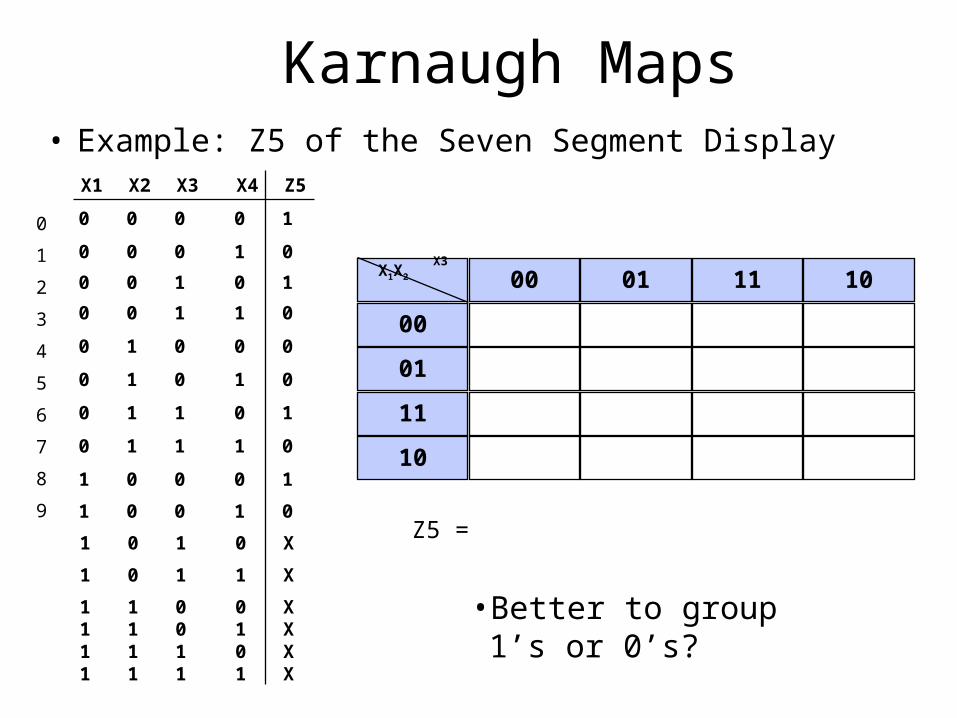
Karnaugh Maps• Example: Z5 of the Seven Segment Display
0 0 0 0 1
0 0 0 1 0
0 0 1 1 0
0 1 0 0 0
0 1 0 1 0
0 1 1 0 1
0 1 1 1 0
1 0 0 0 1
X1 X2 X3 X4 Z5
1 0 0 1 0
1 0 1 0 X
1 0 1 1 X
1 1 0 0 X1 1 0 1 X1 1 1 0 X1 1 1 1 X
0
1
2
3
4
5
6
7
8
9
0 0 1 0 1X1X2
X3 X4 00 01 11 10
00
01
11
10
Z5 =
• Better to group 1’s or 0’s?

Example: Majority Function
• Three inputs: A, B, C• One output: M• Output takes truth value of
majority inputs. I.e.– M is 1 iff two of A,B,C is 1– M is 0 iff two of A, B, C is 0
• Notice writing large truth tables is cumbersome
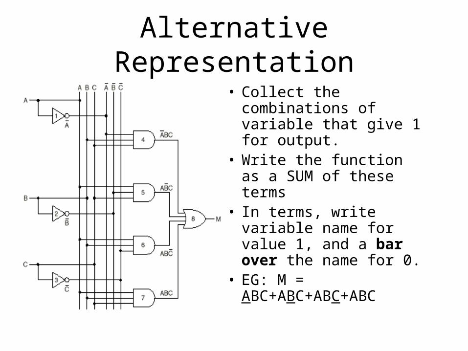
Alternative Representation
• Collect the combinations of variable that give 1 for output.
• Write the function as a SUM of these terms
• In terms, write variable name for value 1, and a bar over the name for 0.
• EG: M = ABC+ABC+ABC+ABC

Rationale for New Notation
• Consider ABC: The product is for AND • Consider ABC+ABC: The sum is for OR• So we are writing the function as a sum of produ
cts• I.e. AND-ing OR-terms – Called conjunctive nor
mal form.• Consider ABC: This is 1 iff A=0, B=1 and C=1• A function of N variables can be given as sum of
2**N n-variable products
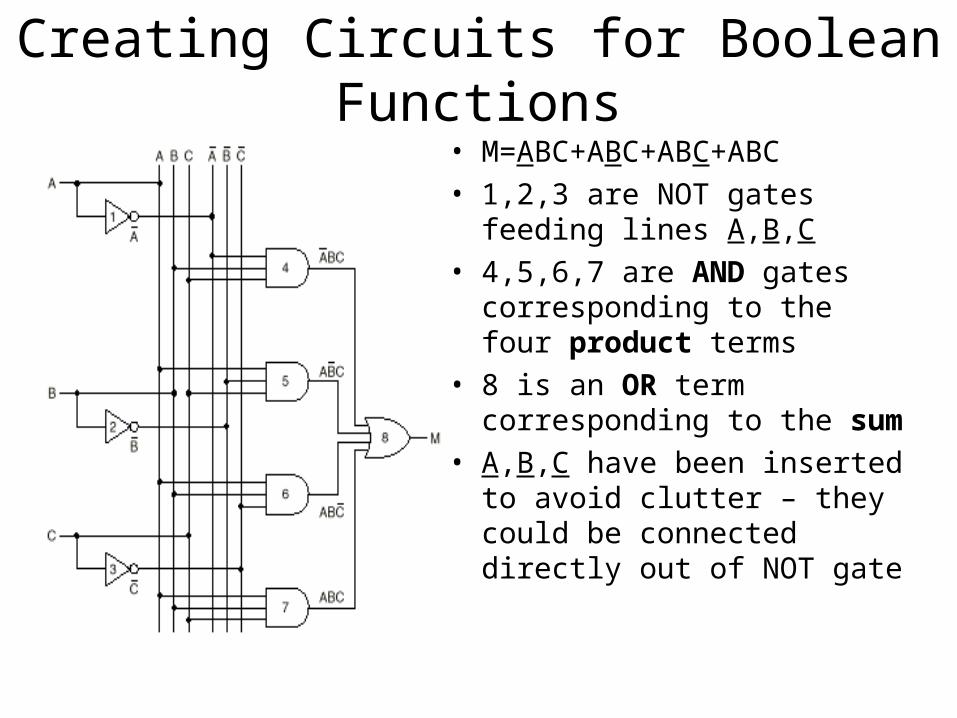
Creating Circuits for Boolean Functions• M=ABC+ABC+ABC+ABC• 1,2,3 are NOT gates feeding
lines A,B,C• 4,5,6,7 are AND gates
corresponding to the four product terms
• 8 is an OR term corresponding to the sum
• A,B,C have been inserted to avoid clutter – they could be connected directly out of NOT gate
Implementing Boolean Functions
• Write the truth table
• Provide inverters for complementing inputs
• Draw an AND gate for each term with 1in output column
• Wire the AND gates to appropriate inputs
• Feed the outputs of all AND gates into an OR gate
Using A Single Gate Type• It is desirable to use only one type of
gate generate the whole circuit.• Can use NAND or NOR gate.• In order to do so, enough to show that
– NOT, AND, OR NAND can be generated by NOR gates
– NOT, AND, OR, NOR ca be generated by NAND gates.
• We say that NAND, NOR are complete for Boolean circuits
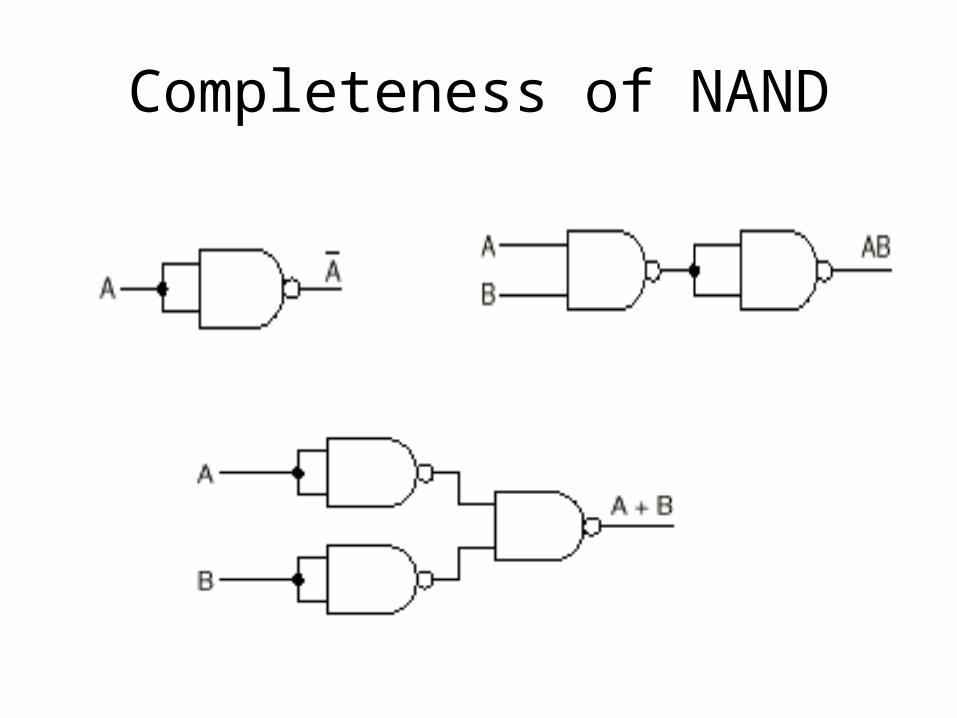
Completeness of NAND
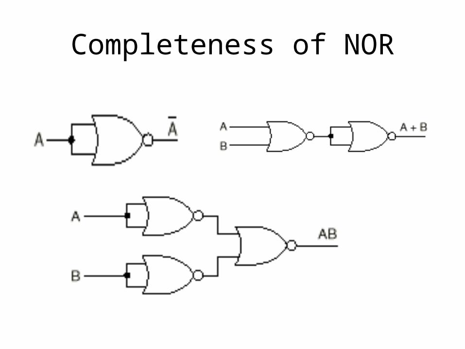
Completeness of NOR
Circuit Equivalence
• Sometimes need to minimize number of elements on a board:– get minimum number of gates– Two input gates instead of four input gates
• Need to find an equivalent circuit for the given circuit
• Equivalent= having same input – output behavior = computing same Boolean function
• Use Boolean Algebra
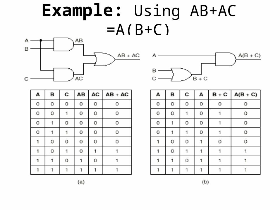
Example: Using AB+AC =A(B+C)
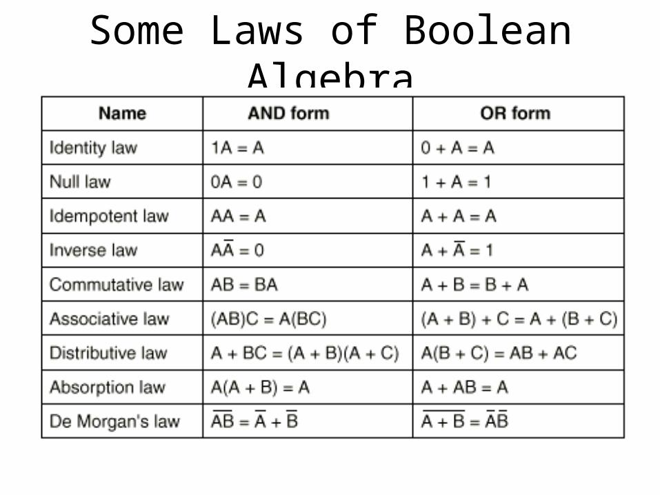
Some Laws of Boolean Algebra
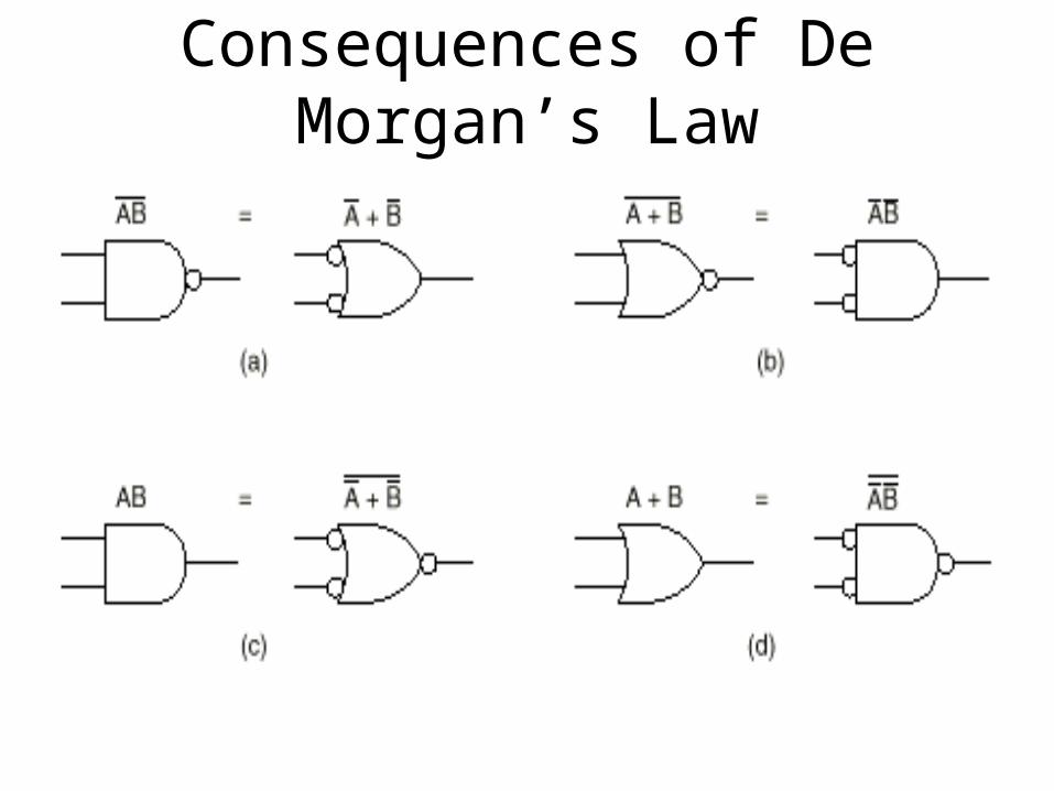
Consequences of De Morgan’s Law
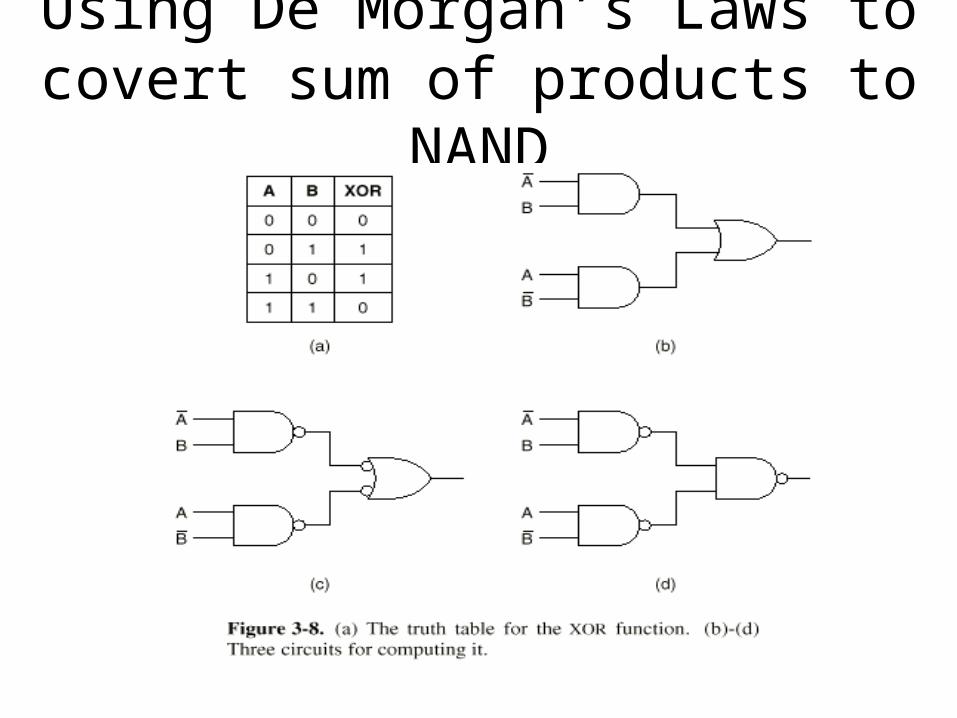
Using De Morgan’s Laws to covert sum of products to NAND
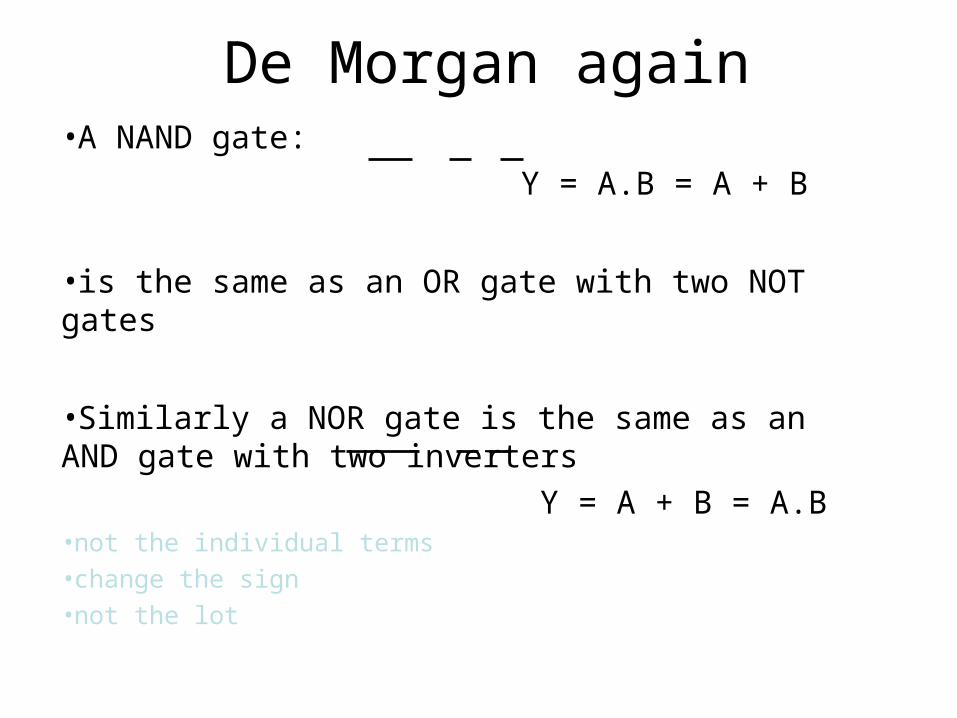
De Morgan again•A NAND gate:
Y = A.B = A + B
•is the same as an OR gate with two NOT gates
•Similarly a NOR gate is the same as an AND gate with two inverters
Y = A + B = A.B•not the individual terms•change the sign•not the lot
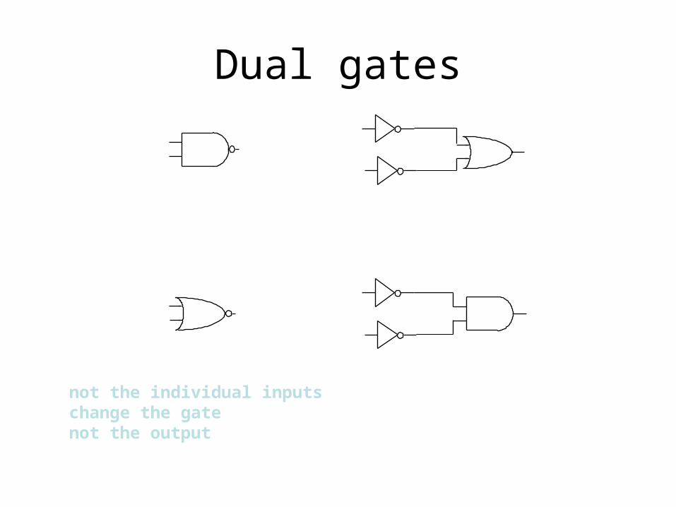
Dual gates
not the individual inputschange the gatenot the output

Truth Tables and Boolean Notation
• NAND Gate Representation– It is possible to i
mplement any boolean expression using only NAND gates
XX
NOT
ANDAB
A.B
A.B
OR
A B A.B
A
A+B
B
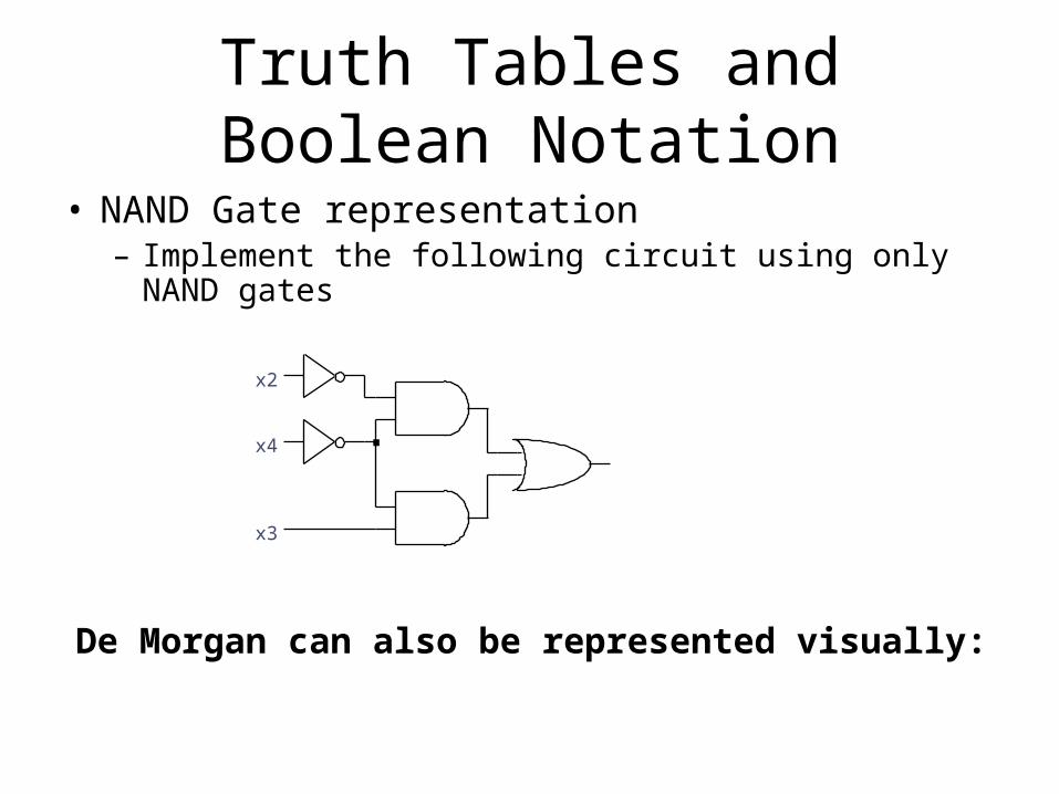
Truth Tables and Boolean Notation
• NAND Gate representation– Implement the following circuit using only NAND gates
x3
x2
x4
De Morgan can also be represented visually:

Exercise• Implement NOT, AND and OR using NOR gates
• Example AND gate dual circuit:
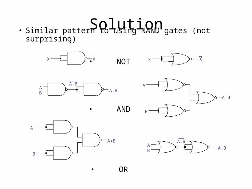
Solution• Similar pattern to using NAND gates (not surprising)
• NOT
• AND
• OR
XX
AB
A.B
A.B
A
A+B
B
XX
AB
A.B
A+B
A
A.B
B
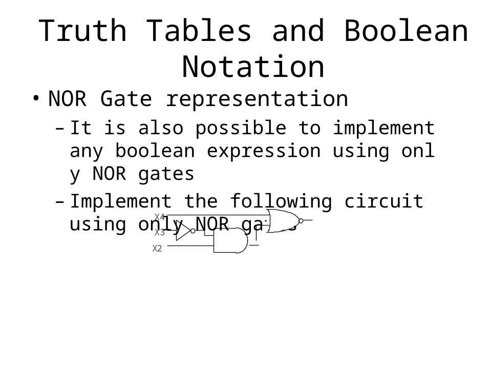
Truth Tables and Boolean Notation
• NOR Gate representation– It is also possible to implement any boolea
n expression using only NOR gates– Implement the following circuit using only N
OR gatesX4
X3
X2
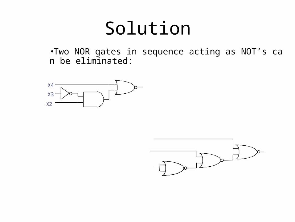
Solution•Two NOR gates in sequence acting as NOT’s can be eliminated:
X4
X3
X2