computational mechanics 25 (2000) 87–98 springer-verlag
TRANSCRIPT

On the accuracy of creep-damage predictionsin thinwalled structures using the finite element method
H. Altenbach, G. Kolarow, O. K. Morachkovsky, K. Naumenko
Abstract The constitutive model with a single damageparameter describing creep-damage behaviour of metalswith respect to the different sensitivity of the damageprocess due to tension and compression is incorporatedinto the ANSYS ®nite element code by modifying the userde®ned creep material subroutine. The procedure is veri-®ed by comparison with solutions for beams and rectan-gular plates in bending based on the Ritz method. Variousnumerical tests show the sensitivity of long-term predic-tions to the mesh sizes and element types available for thecreep analysis of thinwalled structures.
1IntroductionEngineering structures operating at elevated temperaturessuch as fossil power plants, chemical plants, reactors, etc.are designed with respect to increased requirements ofsafety and assurance of long-term reliability. One of themain factors which must be considered in the long-termstructural analysis is time-dependent material behaviourcoupled with damage evolution (Roche et al., 1992). Apowerful tool for the lifetime prediction is the continuumdamage mechanics approach which is based on the for-mulation of constitutive and evolution equations for in-elastic strains and material damage. Incorporating thesematerial models into the ®nite element code predictions oftime-dependent stress, strain and damage ®elds can beperformed by numerical solution of nonlinear initial-boundary value problems (e.g. Hayhurst, 1994). The ®rstproblem arising by creep damage analysis is the formu-lation of a phenomenological material model that is able to
describe the sensitivity of creep strain and damage rate tothe stress level, stress state, temperature level, environ-mental effects, etc. Such a model must be able to extra-polate the experimental creep data usually available fromuniaxial short-term creep tests and realised for narrowstress ranges to the in-service loading conditions in thereal structure. The second problem can be related to thequality of the ®nite element predictions particularly byanalysis of structures with complex shapes.
The structural analysis of thinwalled components(pressure vessels, pipes, pipe bends, etc.) can be per-formed using the mechanical models of plane stress(strain) states or equations of shell theory. In the case ofplane stress (strain) problems numerous ®nite elementsimulations considering creep damage effects has beenmade because of experimental data available for veri®ca-tion. Examples are discussed by Saanouni et al. (1989),Othman et al. (1994), Becker et al. (1994), Murakami andLiu (1995), and Fleig (1996).
Since these examples con®rm the ability of ®nite ele-ment simulations to predict stress redistributions andfailure times with accuracy enough for engineering appli-cations and can be used as benchmark tests by develop-ment of user de®ned material subroutines incorporatingdamage evolution a little effort has been made for theanalysis of transversely loaded thinwalled structures. Nu-merical results for rupture times of rectangular plates inbending are given by Bodnar and Chrzanowski (1994),Bialkiewicz and Mika (1995) based on in-house ®nite el-ement codes and Altenbach and Naumenko (1997) forrectangular plates and Altenbach et al. (1997b) for shells ofrevolution using special numerical methods. The experi-mental study of creep damage of plates and shells is verycomplicated and available experimental data obtained forshort times (e.g. Naumenko, 1996) cannot be used for theveri®cation of long-term predictions. However by somesimpli®cations, e.g. for geometry or loading, it is possibleto formulate the creep problems which can be solved bydirect variational methods using the shape functions de-®ned for the whole domain. Such solutions can be used forthe veri®cation of user de®ned material subroutines and®nite element predictions. If mechanical models of thinshells or plates are used in creep analysis the followingquestions require a special consideration. The ®rst is howsensitive are the long-term predictions of thinwalledstructures with predominating bending stresses to the typeof elements available in ®nite element codes for theiranalysis and to the mesh sizes. The second question isrelated to the ability of the shell theory used in ®nite
Computational Mechanics 25 (2000) 87±98 Ó Springer-Verlag 2000
87
Received 19 September 1999
H. Altenbach (&), K. NaumenkoChair of Engineering Mechanics,Department of Engineering Sciences,Martin-Luther-University Halle-Wittenberg,D-06099 Halle, Germany
G. KolarowDepartment of Strength of Materials, TU So®a,BG-1756 So®a, Bulgaria
O. K. MorachkovskyDepartment of Theoretical Mechanics,Kharkov State Polytechnical University, ul. Frunze, 21,UKR-310 002 Kharkov, Ukraine
Dedicated to our colleague Prof. Dr.-Ing. Yavuz BasËar on theoccasion of the sixty ®fth birthday
brought to you by COREView metadata, citation and similar papers at core.ac.uk
provided by Electronic National Technical University "Kharkiv Polytechnic Institute"...

element codes (usually the Reissner±Mindlin type theory)to represent the time dependent stress redistributionscaused by damage evolution.
This paper presents the results of ®nite element solu-tions using the ANSYS code. Basing on the numericalanalysis only we discuss the following questions. First weconstruct special solutions for beams and plates includingdamage effects based on the Ritz method. These solutionsare used for the veri®cation of the ANSYS user de®nedcreep material subroutine which we modify taking intoaccount the damage evolution. Basing on various numer-ical tests we show the mesh sensitivity of long-term solu-tions in creep bending of beams and plates. Finally wecompare the results for time-dependent de¯ections andstresses based on different plane stress, shell and solidelements available in the ANSYS code for the plasticity andcreep analysis. For the simplicity of numerical studies welimit our discussion to steady state loads and tempera-tures. Further we do not consider the problems of damagelocalization which can cause spurious mesh dependencyand require special regularization techniques (e.g. Saa-nouni et al., 1989; Murakami and Liu, 1995).
2Constitutive modelThe constitutive model for creep behaviour can be for-mulated as a set of ®rst order differential equations for thecreep rate tensor as a function of the stress tensor, thetemperature and possible internal state variables withappropriate evolution equations
_ecr � oF�req;T; H1; . . . ;Hn;x1; . . . ;xm�or
;
_Hi � _Hi�reqH ;T; H1; . . . ;Hn;x1; . . . ;xm�; i � 1; . . . ; n;
_xk � _xk�reqx ;T; H1; . . . ;Hn;x1; . . . ;xm�; k � 1; . . . ;m ;
�1�where _ecr is the creep strain rate tensor, r is the stresstensor, F denotes the creep potential, Hi, xk are hardeningand damage variables. req
H , req and reqx denote the equi-
valent stresses which control the primary, secondary andtertiary creep, respectively. The internal state variables andthe form of the creep potential can be chosen basing onknown mechanisms of creep deformation and damageevolution as well as possibilities of experimental mea-surement and engineering applications (e.g. Chosh andMcLean, 1992). The ®rst step by the conventional creepmodelling is the formulation of an empirical functiondescribing the sensitivity of minimum creep rate to thestress level and temperature. Using the von Mises typepotential the secondary creep constitutive equation can bewritten as follows (e.g. Altenbach, 1999)
_ecr � 3
2
fr�req�req
sfT�T�; req � rvM �������������3
2s � �s
r;
s � rÿ 1
3tr r :
�2�
The mostly used function describing the stress depen-dency fr is the power law function fr�rvM� � A�rvM�n withA and n as material constants determined from uniaxial
creep tests at constant temperature conditions. The tem-perature dependence can be described, for instance, by theArrhenius function (e.g. Nabarro and de Villiers, 1995).
After veri®cation of secondary creep behaviour theminimum creep rate functions can be modi®ed by suitablehardening and damage variables for the description ofprimary and tertiary creep. Following the classical conceptproposed by Kachanov (1986) and Rabotnov (1969) thecreep rate equation (2) can be extended by a scalar damageparameter x and the damage rate is postulated to be afunction of the stress, the temperature and the currentdamage states. The constitutive and evolution equationsfor secondary and tertiary creep behaviour can be writtenas follows
_ecr � 3
2
fr�rvM=1ÿ x�rvM
sfT�T�;_x � gr�req
x �gT�T�gx�x� :�3�
Using the power law functions for fr, gr and gx and as-suming the temperature to be constant during the creepprocess the material model can be formulated as (e.g.Leckie and Hayhurst, 1977; Hyde et al., 1996)
_ecr � 3
2
A�rvM�nÿ1
�1ÿ x�n s; _x � B hreqx i
ÿ �v�1ÿ x�/ ;
reqx � arI � �1ÿ a�rvM;
hreqx i � req
x for reqx > 0;
hreqx i � 0 for req
x � 0; 0 � x � x� :
�4�
Here rI is the maximum principal stress and B, v, /, x�, a,are material constants. This model allows a simple de-scription of creep behaviour and has been veri®ed foruniaxial and multiaxial creep of metals and alloys. Thecoef®cient a controls different damage mechanisms. At thesame time the model re¯ect different sensitivity of thedamage rate to tension and compression loads. However,the models including another kind of functions for stressand damage dependency (e.g. exponential and hyperbolicfunctions) are preferred in last years. The approach pro-posed by Kowalewski et al. (1994) and Perrin and Hayhurst(1994) is based on the introduction of internal variablesand corresponding empirical functions of the stress, thetemperature, etc. based on the mechanisms of deformationand damage evolution known from the material scienceand physics of solids. From the numerical studies of ®nalstage of damage evolution and failure propagation Liu andMurakami (1998) propose to replace the power law damagedependence in the evolution equation (4) by the expo-nential one. The exponential or the hyperbolic functionsprovide stable solutions particularly for the ®nite elementstudies of crack propagation. On the other hand, they canbe motivated by metallographical observations. The studiesof creep in shells discussed by Altenbach et al. (1997b)using the material model (4) and the model presented byKowalewski et al. (1994) con®rm the ability of mechanismbased empirical functions of stress and damage toprovide more adequate life-time predictions. In this paperwe focus our attention to the mesh sensitivity of ®nite el-ement based life-time predictions of thinwalled structures
88

incorporating the material model (4) into ANSYS ®niteelement code and limit our discussion to the numericalstudies of creep behaviour only.
Assuming the elastic properties to be in¯uenced bycreep-damage the elastic constitutive equation coupledwith damage can be represented as follows
rij � Cijkl�x��ekl ÿ ecrkl� �5�
Considering isotropic material the tensor of elastic prop-erties can be written as (Lemaitre and Chaboche, 1990)
Cijkl � E�x�2�1ÿ m2� �1ÿ m��dikdjl � dildjk� � 2mdijdkl
� � �6�The function E�x� is speci®ed as (Liu et al., 1994)
E�x� � E�1ÿ x� (fully coupled approach)
E�x� � E if x < x�0 if x � x�
�(partly coupled approach) ;
�7�E and m denote the Young modulus and the Poisson ratio,respectively. For the numerical convenience we will usehere the following equation
E�x� � E�1ÿ fx�; 0 � f � 1
x�: �8�
The constant f controls the in¯uence of the material de-terioration on the elastic properties. For f � 0 we obtainthe damage uncoupled classical Hooke law, for f � 1=x� ±the fully coupled approach that means the zero stiffness(E � 0) for the critical damage state.
3Creep-damage of beams
3.1Closed estimationsThe Bernoulli beam is one of the simplest mechanicalmodels which allow to construct a special reference solutionand test the ®nite element software incorporating a userspeci®ed material model. First we recall the classical closedsolution for uniaxial steady state creep of a beam (e.g. Boyleand Spence, 1983). Neglecting the elastic strain eel � ecr andthe damage evolution in the material model (4) the consti-tutive equation for the beam can be written as
_e�x; z; t� � _ecr�x; z; t�� ÿ _w�x; t�00z � Ajr�x; z; t�jnÿ1r�x; z; t� ; �9�
where w�x� is the de¯ection function, x is the beam axis(0 � x � l) and z is the normal axis (ÿh=2 � z � h=2).From Eq. (9) follows
r�x; z; t� � ÿ _w�x; t�00A
� �1n
jzj1ÿnn z : �10�
The integration over the beam cross section Ac � hb�z�,which is assumed to be symmetrical, yields
M�x� �Z
Ac
rz dAc � In ÿ _w�x; t�00A
� �1n
�11�
with
In �Z h=2
ÿh=2
jzjn�1n b�z�dz � 2
Z h=2
0
jzjn�1n b�z�dz ;
as the generalised moment of inertia.For a statically determined beam the Eq. (11) yields a
solution for the de¯ection function in steady state creep.As an example we consider a beam simply supported onboth edges and loaded by a uniformly distributed force q.In this case M�x� � qx�lÿ x�=2 and the Eq. (11) can berewritten as
_w�x�00 � ÿ A
Inn
qn
2nxn�lÿ x�n; 0 � x � l : �12�
For integer values of the power n the solution is a poly-nomial of the order 2n� 2
_w�x� � A
Inn
qn
2nx�lÿ x�
Xn
k�0
Xn�k
i�0
akl2nÿixi;
ak � �ÿ1�k
n
k
!1
�n� k� 1��n� k� 2� :
Comparing with the approximation from the elasticsolution
w�x� � q
24EIx�xÿ l��x2 ÿ lxÿ l2� ;
with I as the moment of inertia one can conclude that ifthe creep problem is numerically solved using variationalor energy based methods the shape functions for the de-¯ection or de¯ection rate should contain the polynomialterms of the order 2n� 2. Further even for analysis ofsteady state creep using the power low stress dependencean accurate solution cannot be obtained with approxima-tions justi®ed for the elasticity solution.
In order to estimate the solution including damage wemake two simpli®cations that the damage do not accu-mulate during the transition from the elastic to steadycreep state and the damage rate is the same for positiveand negative stresses. From the constitutive equation (4)follows
r�x; z; t� � �1ÿ x�x; z; t�� ÿ _w�x; t�00A
� �1n
jzj1ÿnn z : �13�
The integration over the cross section yields
M�x� �Z h=2
ÿh=2
rb�z�z dz
� �In ÿ Inx�x; t�� ÿ _w�x; t�00A
� �1n
�14�
with
Inx�x; t� � 2
Z h=2
0
x�x; z; t�jzjn�1n b�z�dz : �15�
For the example considered we can write the followingdifferential equation
89

_w�x; t�00 � ÿAqn
2nxn�lÿ x�n 1
�In ÿ Inx�x; t��n : �16�
With respect to Eq. (13) the damage evolution equation (4)can be written as
_x�x; z; t� � B�1ÿ x�x; z; t��vÿ/ ÿ _w�x; t�00A
jzj� �v
n
z :
�17�Averaging over the cross section yields
_Inx�x; t� � 2
Z h=2
0
_x�x; z; t�jzjn�1n b�z�dz
� 2B ÿ _w�x; t�00A
� �vn
�Z h=2
0
�1ÿ x�x; z; t��vÿ/jzjn�v�1n b�z�dz :
�18�This equation can be simpli®ed for the special case v � /as
_Inx�x; t� � B ÿ _w�x; t�00A
� �vn
Inv �19�
with
Inv � 2
Z h=2
0
jzjn�v�1n b�z�dz :
Using the Eq. (16) we obtain
_Inx�x; t� � BInvqv
2vxv�lÿ x�v 1
�In ÿ Inx�x; t��v : �20�
After the integration with respect to time we get
In ÿ Inx�x; t�
� In
�1ÿ �v� 1�BInv
qv
2vIv�1n
xv�lÿ x�vt
� 1v�1
: �21�
Substitution into Eq. (16) yields
_w�x; t�00 � ÿAqn
2nInn
xn�lÿ x�nf �x; t� �22�
with
f �x; t� � 1ÿ �v� 1�BInvqv
2vIv�1n
xv�lÿ x�vt
� �ÿ nv�1
:
�23�From Eq. (15) follows that the condition Inx�xf; tf � � In ispossible in the case of completely damaged cross sectionxf only. In this case the left part of Eq. (21) vanishes andthe function f �xf ; tf � in Eq. (23) tends to in®nity for thecross section xf . If the numerical study performed until thedamage parameter x�x; z; t� attains the critical value in apoint P�xf ; zf � for t � t�, Inx�x; t� < In holds true andEq. (23) can be represented as a convergent polynomial
series of x for each 0 � t � t�. Consequently there exista convergent solution _w�x; t� which can be representedas a polynomial series of x containing at least the order2n� 2. In the following we con®rm these estimationssolving the problem by the Ritz method and constructsome convergent test solutions.
3.2Solutions based on the Ritz methodStarting from Hooke's law (5) applied to the beam bendingproblem (Pilkey and Wunderlich, 1994)
r � E�1ÿ fx��eÿ ecr�� ÿE�1ÿ fx��ÿu00 ÿ w00z� ecr� ; �24�
with u0 as the axial displacement of the beam centreline,the principle of virtual displacements yieldsZ
V
rde dV � E
Zx
�I ÿ xzzz�w00dw00 dx
� E
Zx
�Ac ÿ xz�u00du00 dx
� E
Zx
xzzd�u00w00�dx� E
Zx
Mcrdw00 dx
ÿ E
Zx
Ncrdu00 dx
�Z
xqdw dx
with
Mcr �Z
Ac
�1ÿ fx�ecrz dAc; Ncr �Z
Ac
�1ÿ fx�ecr dAc;
xz �Z
Ac
x dAc; xzz �Z
Ac
xz dAc; xzzz �Z
Ac
xz2 dAc :
Assuming the creep strain and the damage parameter to beknown functions of the coordinates x and z for the ®xedtime t we can formulate the following functional
Pt�w; u0� � 1
2E
Zx�I ÿ xzzz�w002 dx
� 1
2E
Zx
�Ac ÿ xz�u020 dx� E
Zx
xzzu00w00 dx
� E
Zx
Mcrw00 dxÿ E
Zx
Ncru00 dx
ÿZ
x
qw dx :
This leads to the problem to ®nd such functions w and u0
that yield an extremal value of the functional. The solu-tions for ®xed time t can be represented as
w�x� � aw0 uw
0 �x� �XN
i�1
awi uw
i �x�; u0�x� �XM
i�0
aui u
ui �x� :
�25�
90

For the simply supported beam discussed above the shapefunctions can be formulated as follows:
uw0 �x� � x �xÿ l��x2 ÿ lxÿ l2�
is the ®rst approximation following from the elastic solu-tion. For uw
i �x� we use functions satisfying the boundaryconditions w � 0 and M � 0 for x � 0 and x � l:� polynomials
uwi �x� � xi�2�lÿ x�i�2 �26�
� eigenfunctions of a transverse vibrating beam
uwi �x� � sin
�2iÿ 1�px
l: �27�
Assuming u0 � 0 for the edge x � 0 the functionsuu
i �x� � xi�1 can be used. Summarising the unknownconstant coef®cients into the vector aT � �awT
; auT � withawT � �aw
0 ; awi �, i � 1; . . . ;N and auT � �au
i �, i � 1; . . . ;M,the Ritz method yields a set of linear algebraic equations
oPtoak� 0;
Rww Rwu
Ruw Ruu
� �aw
au
� �� fw
fu
� ��28�
with
Rwwkj � E
Z l
0
�I ÿ xzzz�uwk00uw
j00 dx;
k � 1; . . . ;N; j � 1; . . . ;M
Rwukj � E
Z l
0
xzzuwk00uu
j0 dx; k � 1; . . . ;N; j � 1; . . . ;M
Ruukj � E
Z l
0
�Ac ÿ xz�uuk0uu
j0 dx;
k � 1; . . . ;M; j � 1; . . . ;M
Ruwkj � E
Z l
0
xzzuuk0uw
j00 dx; k � 1; . . . ;M; j � 1; . . . ;N
f wk � q
Z l
0
uwk dxÿ E
Z l
0
Mcruwk00 dx; k � 1; . . . ;N
f uk � E
Z l
0
Ncruuk0 dx; k � 1; . . . ;M :
After the solution of the system (28), the stress r�x; z; t�can be calculated from the Eq. (24). For the known valuesof the stress and the damage parameter the constitutivemodel (4) yields the rates of creep strain and damage forthe time t. From these the new values for time t � Dt arecalculated using the implicite time integration procedure
ecr�x; z; t � Dt� � ecr�x; z; t� � Dt��1ÿ h� _ecr�x; z; t�� h _ecr�x; z; t � Dt��;
x�x; z; t � Dt� � x�x; z; t� � Dt��1ÿ h� _d�x; z; t�� h _x�x; z; t � Dt��;
ecr�x; z; 0� � 0; x�x; z; 0� � 0; x�x; z; t� < x� :
For the calculation of the creep force Ncr, the creepmoment Mcr as well as damage averages xz, xzz and xzzz
in Eq. (24) the Gauss method with 9 integration points inthe thickness direction is used. For the calculation of thematrices Rmn and the right parts of the equation set (28)
the Simpson quadrature rule with Ns integration points inthe beam axis x is used. The values of creep strain anddamage for a current time step t are stored in all inte-gration points along the beam axis and over the thicknessdirection for calculations in the next time step. The ac-curacy of the numerical solution depends on the numberof shape functions in Eq. (25), on the number of integra-tion points and on the time step size. The sensitivity ofcreep solutions to time step sizes has been previouslystudied by Altenbach and Naumenko (1997) on the platebending problems. In the following numerical exampleswe will put our attention to the convergence study of thetime dependent solution using different number of shapefunctions in Eq. (24).
As a ®rst example we consider the above discussedsimply supported beam with a rectangular cross sectionb�z� � const. For the calculation we set q � 60 N/mm,l � 1000 mm, h � 80 mm, b � 30 mm and use the creep-damage material model (4) modi®ed with time-hardeningfunction which allows the description of the primary creep
_ecr � 3
2
A�rvM�nÿ1
�1ÿ x�n stm; _x � B�hreqx i�v
�1ÿ x�/ tm : �29�
In the following we will use the material constants iden-ti®ed by Kowalewski et al. (1994) for an aluminium alloy:A � 3:511� 10ÿ31 MPaÿn=hm�1, B � 1:960� 10ÿ23
MPaÿv =hm�1, v � 8:220, n � 11:034, / � 12:107,m � ÿ0:3099 and E � 7:1� 104 MPa, m � 0:3. Eq. (29) canbe transformed into Equation (4) introducing the timevariable s � tm�1=�m� 1�. For the ®rst example we ne-glect the in¯uence of creep damage on elasticity settingf � 0 in Eq. (8). Further we assume the damage rate to bethe same for tensile and compressive loading setting a � 0in Eq. (4). Both the assumptions lead to a signi®cantsimpli®cation of the numerical procedures. Using the ®rstone we can set Ruw � Rwu � 0 in Eq. (28) and keep thematrices Rww, Ruu constant during the time step calcula-tion. The second results to symmetric stress redistribu-tions across the z direction for the arbitrary time stepwhich leads to Ncr � 0 and fu � 0. Consequently thenumber of functions in the approximation for the dis-placement u0 has no in¯uence on the numerical solutions.
Figure 1 shows time dependent solutions for maximumde¯ection and maximum stress obtained by differentnumber of polynomial terms (26) in Eq. (25). The timestep solutions are performed until the critical damage isachieved in one of the integration points. The conditionof termination of the time step solution isx�xf ; zf ; t�� > 0:9, where the integration point P�xf ; zf �can be speci®ed as a point of failure initiation and thetime step t� as the time to failure initiation.
Since all approximations of the de¯ection functionused for the Ritz method yield the exact elasticity solution,the life-time predictions are strongly sensitive to thenumber of shape functions, Fig. 1. Even for the case of astatically determined beam one can conclude that theapproximation adjusted for the elastic solution cannot beused for the creep-damage predictions. The differencebetween the life-time predictions based on an approxi-mation following from the elastic solution (fourth order
91

polynomial), curves 1, and approximation which followsfrom above discussed steady state creep solution (poly-nomial of the order 24, curve 4) is approximately six times.From the Fig. 2 can be seen that the creep-damage solutionconverges with the increasing number of shape functions.The approximations with N � 5, N � 7 and N � 8 yieldthe same solutions for the transition and steady state creepstate but differ in the last stage. This is in agreement withthe above conclusion that the consideration of damageneeds an increased order of approximation in comparisonwith the steady state creep solution. Since the differencebetween the cases 4 and 6 (approximately 17%) is notacceptable comparing with the accuracy of the availablematerial description one can conclude that the order ofapproximation adjusted for the steady state creep solutioncan be enough for the numerical life-time predictionsusing continuum damage mechanics approach. Compar-ing with the polynomial approximation (26) the eigen-functions of transverse beam vibration (27) provide abetter convergence, Fig. 3. These functions we will use inthe analysis of plates in bending below.
In addition to convergence studies, we show thein¯uence of the constant f in Eq. (8) which allows totake into account the drop of elastic stiffness with creep
damage accumulation. For the beam considered wecompare two convergent solutions obtained by settingf � 0 and f � 1 in Eq. (28). The results for the timedependent maximum de¯ection, maximum stress, as wellas creep strain and damage parameter for the integration
Fig. 1a, b. Solutions for a Bernoulli beam based on the Ritz method using the approximation (25) and polynomial functions (26):a time variation of maximum de¯ection; b time variation of maximum stress, 1±approximation using elastic de¯ection function,2 ± N � 1; 3 ± N � 2; 4 ± N � 8
Fig. 2a, b. Convergence of time-dependent solution for a Bernoulli beam using polynomial functions (26): a time variation ofmaximum de¯ection; b time variation of maximum stress, 1 ± N � 1; 2 ± N � 2; 3 ± N � 3; 4 ± N � 5; 5 ± N � 7; 6ÿ N � 8
Fig. 3. Convergence of time-dependent solution for a Bernoullibeam using the approximation (25) and eigenfunctions oftransverse vibration (27): 1 ± N � 2; 2 ± N � 3; 3 ± N � 4
92

point corresponding to x � l=2; z � h=2 are plotted in Fig.4. The results for the both cases differ on the last stagebefore the failure initiation. The fully coupled approachf � 1 yields the complete stress relaxation and a larger rateof de¯ection growth for the last stage. The consideration ofsuch effects can be necessary for numerical studies offailure propagation within the framework of continuumdamage mechanics (e.g. Saanouni et al., 1989; Murakamiand Liu, 1995). But if only the life-time to the failure ini-tiation have to be analysed the uncoupled approach f � 0 isenough for the numerical predictions. The difference be-tween failure times for both cases is not signi®cant. Inaddition, it should be noted that by using the coupled ap-proach f > 0 the computational effort suf®ciently increasesbecause the matrices R in Eq. (28) have to be modi®ed oneach time or iteration step with the damage ®eld functionsobtained in the discretization points. Since the damagelocalizes at the last stage of calculation it needs a veryprecise integration (great number of integration points)and a very accurate time step method. This has been pre-viously observed in different ®nite element calculations(e.g. Saanouni et al., 1989; Murakami and Liu, 1995).
3.3Finite element solutionUsing the ANSYS User Programmable Features we haveincorporated the material model (4) into the ANSYS ®niteelement code by modi®ying the user creep material sub-routine. For details of time integration and equilibrium
iteration methods used in ANSYS for creep calculations werefer to ANSYS User's Manual Volume I±IV (1994) andZienkiewicz and Taylor (1991).
For testing of the implemented material law we intro-duce the beam considered below as the ®rst example. Forthe meshing we use the 4 node shell element SHELL 43available for creep computations. This element is based onthe Reissner±Mindlin type shell theory and contains 2� 2Gauss points in the plane and ®ve integration pointsthrough the thickness. The automatical time steppingfeature with a minimum time step 0:1 h has been used.Figure 5 shows the solutions with respect to differentmeshes. The convergent solution (case 6) has been ob-tained with 200 elements and after 96 time steps. Thissolution has a very good agreement with the solution ob-tained using the Ritz method, Fig. 2. Similarly to thesensitivity of the solution to the degree of the polynomialdiscussed below the mesh sensitivity of the ®nite elementsolution can be observed. The mesh justi®ed for the elasticsolution (case 1) is not ®ne enough. The solutions in thecases 3±6 are approximately the same in the steady stateand slightly differ in the last stage. Since for the largestructures including stress singularities is dif®cult to testthe mesh sensitivity performing the whole creep damagecalculations one can conclude that convergent solution forthe steady state creep which does not require many timesteps, can provide an adequate (at least qualitatively cor-rect) solution within the framework of continuum damagemechanics.
Fig. 4a±d. In¯uence of the parameter f in Eq. (8) on time variations for: a maximum de¯ection; b maximum stress; c creep strain;d damage parameter, 1 ± f � 0 uncoupled approach, 2 ± f � 1 fully coupled approach
93

In the previous examples we assumed the damageevolution to be the same by tensile or compressive loading.The next example illustrate the time dependent solutionsof a beam setting damage rate to zero in the Gauss points
with negative maximum principal stress. In order tocompare the in¯uence of the element type on the creepdamage solutions we performed the calculations using theelement SHELL 43 with 80 elements and the 4-node planestress element PLANE 42 meshing the beam with 80 ele-ments along the beam axis and 4 elements along thenormal axis. Figure 6 shows the time dependent solutionsfor maximum de¯ection obtained with shell elements,plane stress elements and using the Ritz method. It can beseen that if the sensitivity of material damage to the kindof stress state is taken into account results obtained byshell and plane elements substantively differ. The differ-ence in the life-time prediction is approximately 30%. Forthe comparison two convergent solutions based on theRitz method applied for a beam with the Bernoulli as-sumptions are plotted. The ®rst solution is obtained with 5Gauss points for the thickness integration (curves 3), andthe second with 9 Gauss points (curves 4). Both thesolutions are obtained with the same number of the shapefunctions, N � 8, M � 8 in Eqs. (25). The solution with 9Gauss points is in better agreement with the plane stresssolution which is seen particularly on the time variation ofmaximum negative stress, Fig. 7b. The solution with 5Gauss points agree better with the solution with the shellelement. Since the element SHELL 43 contains 5 Gauss
Fig. 5a, b. Solutions for a Bernoulli beam using the ANSYS code with plastic shell elements SHELL 43: a time variation of maximumde¯ection; b time variation of maximum stress, 1 ± 8 elements, 2 ± 10 elements, 3 ± 20 elements, 4 ± 40 elements, 5 ± 80 elements,6 ± 200 elements
Fig. 6. Time dependent de¯ection of a beam: 1 ± SHELL 43, 2 ±PLANE 42, 3 ± Ritz method with 5 Gauss points for thicknessintegration, 4 ± Ritz method with 9 Gauss points for thicknessintegration
Fig. 7a, b. Time dependent stresses for a beam: a positive stress on the bottom side; b negative stress on the top side, curve symbolssee Fig. 6
94

points for the thickness integration (see ANSYS User'sManual Volume I±IV, 1994), one can conclude that moreaccurate thickness integration should be performed usingshell elements in creep damage computations with mate-rial models re¯ecting different sensitivity of damage evo-lution to tensile and compressive loading.
4Creep-damage of plates in bendingAs the second mechanical model for the veri®cation ofuser material subroutine let us introduce the thin plateproblem. Analogously to the Bernoulli beams we formulatethe variational problem for the thin plate using theKirchhoff assumptions. Further we include geometricalnonlinear terms for consideration ®nite de¯ection in thesense of the von KaÂrmaÂn plate theory. In Altenbach andNaumenko (1997) and Altenbach et al. (1997a) we dis-cussed the governing equations of the plate theory in-cluding creep strains and damage. The variationalfunctional in the mixed form can be written as follows�i; j; k; l � 1; 2�
P�U;w� � 1
2
ZA
�ÿ�gIijkl�ÿ1Nij�U�Nkl�U�
� gIIijkllij�w�lkl�w��dA
�Z
A
1
2Nij�U�lij�w�w dA
ÿZ
A
�qw� �gIijkl�ÿ1Ncr
ij Nkl�U�
�Mcrij lij�w��dA ; �30�
where w is the de¯ection function, lij denote the curvaturechanges and twist of the midsurface, Nij are membraneforces, A is the plate area and h is the plate thickness. Nij
can be expressed with the Airy stress function U and lijwith the de¯ection function as follows
N11�U� � U;22; N22�U� � U;11; N12�U� � ÿU;12;
lij�w� � ÿw;ij :
The de¯ection function and the Airy stress function de-pend on the cartesian coordinates x; y � �. . .�; 1; �. . .�; 2denote the derivatives with respect to x and y. For the ®xedtime variable we can introduce the thickness averages ofcreep strains, assuming for the simplicity f � 0 in Eq. (8)
Ncrij �
Zh
Cijklecrkl dz; Mcr
ij �Z
h
Cijklecrklz dz ;
with
gIijkl � Cijklh; gII
ijkl � Cijklh3=12; i; j; k; l � 1; 2
�gIijkl�ÿ1 � 1
2Eh��dikdjl � dildjk��1� m� ÿ 2mdijdkl� :
This simpli®cation can be made due to the small in¯uenceof f on the failure times (as was shown by beam calcula-tions) and the signi®cant increasing of the computationalefforts. Limiting our discussion to rectangular plates�l1 � l2� we can solve the variational problem with fol-lowing approximations �n � x=l1; g � y=l2)
w�n; g� � a0Xwn0�n�Xw
g0�g� �XN
i�1
XN
j�1
awij X
wni�n�Xw
gj�g�;
U�n; g� �XM
i�1
XM
j�1
aUij XU
ni�n�XUgj�g� ; �31�
with the shape functions de®ned for the whole plate do-main. The product function Xw
n0�n�Xwg0�g� is formulated as
the elastic de¯ection function by given applied load. Theprocedure for the construction of such a function basingon the Vlasov-Kantorovich method and variational itera-tions is discussed in Altenbach et al. (1998a), Altenbachet al. (1998b). The functions Xw
ni�n� and XUni�n� are chosen
as eigenfunctions of transversely vibrating beam
Xwni�n� � sin lnÿ sinh ln
ÿ sin lÿ sinh lcos lÿ cosh l
�cos lnÿ cosh ln�;
XUni�n� � sin ipn; i � 1; 3; 5; . . .
�32�
with
l � 2i� 1
2p; i � 1; 3; 5; . . . :
These functions satisfy exactly the essential boundaryconditions for the edges x � const
w � 0; w;1 � 0; n11 � U;22 � 0
and y � const
w � 0; w;2 � 0; n22 � U;11 � 0
The solution method for the creep problem of a platewhich is similar to the above discussed procedure for abeam is discussed in detail in Altenbach and Naumenko(1997) and Altenbach et al. (1997a).
On Fig. 8 the time-dependent maximum de¯ection for aclamped square plate transversely loaded by q � 10 MPauniformly distributed on a square area is presented. The
Fig. 8. Time-dependent maximum de¯ection of a clampedsquare plate: 1 ± SHELL 43, 2 ± SOLID 95, 3 ± solution basing onthe Ritz method (Kirchhoff's theory)
95

plate length is l � 800 mm and the thickness ± h � 27 mm.The material constants are the same as in examples forbeams. In the ®rst example we set a � 0 in Eqs. (4) as-suming the damage evolution to be dependent on the vonMises stress only. This dependency assume the samedamage rate for the tensile and compressive loading. The®rst solution (Fig. 8, curve 1) has been obtained using therectangular shell elements and a 20� 20-element mesh fora quarter of the plate. The second solution (Fig. 8, curve 2)is based on 20-nodes solid element (3D) and 20� 20-elements for a quarter of the plate and 3 elements in thethickness direction. The third solution is obtained usingthe Ritz solution technique. All solutions are in a goodagreement. In addition, the good agreement of these threesolutions can be seen on Fig. 9 for time variation of thevon Mises stress plotted in two Gauss points (in the middleof the plate, bottom side and in the middle of the clampededge, top side). In the second example we set a � 1 in thematerial model (4) assuming the rI-dependency of thedamage evolution.
Figure 10 shows three convergent solutions for thetime-dependent maximum de¯ection obtained using shellelements, solid elements and the Ritz method. The dif-ferences between the cases 1 (SHELL 43, Reissner±Mindlintype element) and 3 (Ritz method, Kirchhoff theory) canbe explained as the in¯uence of the shear correction. Thisin¯uence is possible due to the differences of damageevolution by tensile and compressive loading which inducea nonsymmetric deformation in the thickness direction.Since the elastic solutions are the same for the startingtime, the time dependent de¯ection obtained using theReissner±Mindlin theory is greater during the creep pro-cess. The failure times predicted using ®nite elementconcept with shell elements agree with that basing on theKirchhoff plate theory and the Ritz method. In contrast,the result obtained with solid elements signi®cantly differsfrom both the previous cases (curve 2). The explanationof this is presented in Fig. 11, where the maximum prin-cipal stress is plotted as a function of time in two Gausspoints of the plate domain. Since both the plate theoriesyield approximately the same values of the maximumprincipal stress during the whole creep process, the 3Dtheory yields the principal stress in the midpoint of the
plate edge which is too high comparing with those forplate theories.
For the further explanation we refer to Okumura andOguma (1998) where a closed series solution of 3D equa-tions of elasticity for a clamped rectangular plate is dis-cussed. The authors have shown that at the upper (lower)corners of the plate edge the 3D elasticity equations yield asingular solution for the normal stresses (the shear stressesare ®nite). The ®nite element result con®rms the closedsolution yielding to high values of normal stresses and thecorresponding value of the maximum principal stress leadto a short failure time. Further as shown by Okumura andOguma (1998) ry � rz in the middle point of the plate. Incontrast, the plate theories yield either zero or small valuesof the normal stress rz compared with rx and ry. Sincerx; ry and rz are much greater than the shear stresses, theprincipal stresses are approximately equal to the normalstresses rI � rx; rII � ry and rIII � rz. Because rII � rIII
in the midpoint of the clamped edge Okumura and Oguma(1998) we can estimate the von Misses stress arvM � rI ÿ rIII. Since the ®nite element solution yieldlarge but nonsingular values of rI and rIII (rI > rIII) thevon Mises stress rvM � rI. This gives the explanation that
Fig. 9a, b. Time variations of the von Mises stress in two points: a midpoint of the bottom side; b midpoint of the clamped edge(top side), curve symbols see Fig. 8
Fig. 10. Time-dependent de¯ection of a clamped square plate,with rI damage criterion: 1 ± SHELL 43, 2 ± SOLID 95, 3 ±solution based on the Ritz method (Kirchhoff theory)
96
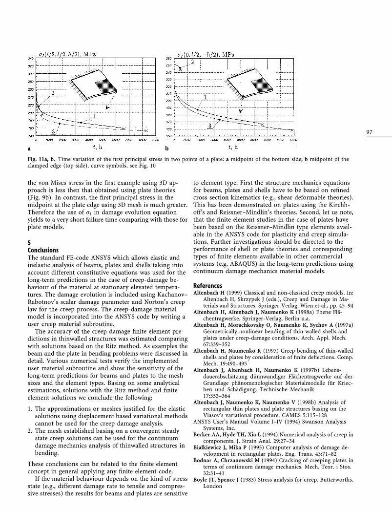
the von Mises stress in the ®rst example using 3D ap-proach is less then that obtained using plate theories(Fig. 9b). In contrast, the ®rst principal stress in themidpoint at the plate edge using 3D mesh is much greater.Therefore the use of rI in damage evolution equationyields to a very short failure time comparing with those forplate models.
5ConclusionsThe standard FE-code ANSYS which allows elastic andinelastic analysis of beams, plates and shells taking intoaccount different constitutive equations was used for thelong-term predictions in the case of creep-damage be-haviour of the material at stationary elevated tempera-tures. The damage evolution is included using Kachanov±Rabotnov's scalar damage parameter and Norton's creeplaw for the creep process. The creep-damage materialmodel is incorporated into the ANSYS code by writing auser creep material subroutine.
The accuracy of the creep-damage ®nite element pre-dictions in thinwalled structures was estimated comparingwith solutions based on the Ritz method. As examples thebeam and the plate in bending problems were discussed indetail. Various numerical tests verify the implementeduser material subroutine and show the sensitivity of thelong-term predictions for beams and plates to the meshsizes and the element types. Basing on some analyticalestimations, solutions with the Ritz method and ®niteelement solutions we conclude the following:
1. The approximations or meshes justi®ed for the elasticsolutions using displacement based variational methodscannot be used for the creep damage analysis.
2. The mesh established basing on a convergent steadystate creep solutions can be used for the continuumdamage mechanics analysis of thinwalled structures inbending.
These conclusions can be related to the ®nite elementconcept in general applying any ®nite element code.
If the material behaviour depends on the kind of stressstate (e.g., different damage rate to tensile and compres-sive stresses) the results for beams and plates are sensitive
to element type. First the structure mechanics equationsfor beams, plates and shells have to be based on re®nedcross section kinematics (e.g., shear deformable theories).This has been demonstrated on plates using the Kirchh-off's and Reissner±Mindlin's theories. Second, let us note,that the ®nite element studies in the case of plates havebeen based on the Reissner±Mindlin type elements avail-able in the ANSYS code for plasticity and creep simula-tions. Further investigations should be directed to theperformance of shell or plate theories and correspondingtypes of ®nite elements available in other commercialsystems (e.g. ABAQUS) in the long-term predictions usingcontinuum damage mechanics material models.
ReferencesAltenbach H (1999) Classical and non-classical creep models. In:
Altenbach H, Skrzypek J (eds.), Creep and Damage in Ma-terials and Structures. Springer-Verlag, Wien et al., pp. 45±94
Altenbach H, Altenbach J, Naumenko K (1998a) Ebene FlaÈ-chentragwerke. Springer-Verlag, Berlin u.a.
Altenbach H, Morachkovsky O, Naumenko K, Sychov A (1997a)Geometrically nonlinear bending of thin-walled shells andplates under creep-damage conditions. Arch. Appl. Mech.67:339±352
Altenbach H, Naumenko K (1997) Creep bending of thin-walledshells and plates by consideration of ®nite de¯ections. Comp.Mech. 19:490±495
Altenbach J, Altenbach H, Naumenko K (1997b) Lebens-dauerabschaÈtzung duÈnnwandiger FlaÈchentragwerke auf derGrundlage phaÈnomenologischer Materialmodelle fuÈr Kriec-hen und SchaÈdigung. Technische Mechanik17:353±364
Altenbach J, Naumenko K, Naumenko V (1998b) Analysis ofrectangular thin plates and plate structures basing on theVlasov's variational procedure. CAMES 5:115±128
ANSYS User's Manual Volume I±IV (1994) Swanson AnalysisSystems, Inc.
Becker AA, Hyde TH, Xia L (1994) Numerical analysis of creep incomponents. J. Strain Anal. 29:27±34
Bialkiewicz J, Mika P (1995) Computer analysis of damage de-velopment in rectangular plates. Eng. Trans. 43:71±82
Bodnar A, Chrzanowski M (1994) Cracking of creeping plates interms of continuum damage mechanics. Mech. Teor. i Stos.32:31±41
Boyle JT, Spence J (1983) Stress analysis for creep. Butterworths,London
Fig. 11a, b. Time variation of the ®rst principal stress in two points of a plate: a midpoint of the bottom side; b midpoint of theclamped edge (top side), curve symbols, see Fig. 10
97

Chosh RN, McLean M (1992) High temperature deformation inengineering alloys-modelling for strain of load control. ActaMetall. Mater. 40:3075±3083
Fleig T (1996) Lebensdaueranalyse unter BeruÈcksichtigungviskoplastischer Verformung und SchaÈdigung mit derMethode der Finite Elemente. Dissertation, UniversitaÈtKarlsruhe
Hayhurst DR (1994) The use of continuum damage mechanics increep analysis for design. J. Strain Anal. 25:233±241
Hyde TH, Xia L, Becker AA (1996) Prediction of creep failure inaeroengine materials under multi-axial stress states. Int. J.Mech. Sci. 38:385±403
Kachanov L (1986) Introduction to Continuum Damage Me-chanics. Martinus Nijhoff Publishers, Dordrecht
Kowalewski ZL, Hayhurst DR, Dyson BF (1994) Mechanism-based creep constitutive equations for an aluminium alloy.J. Strain Anal. 29:309±316
Leckie F, Hayhurst D (1977) Constitutive equations for creeprupture. Acta Metall. 25:1059±1070
Lemaitre J, Chaboche JL (1990) Mechanics of Solid Materials.Cambridge University Press, Cambridge.
Liu Y, Murakami S (1998) Damage localization of conventionalcreep damage models and proposition of new model for creepdamage analysis. JSME 41:57±65
Liu Y, Murakami S, Kanagawa (1994) Mesh-dependence andstress singularity in ®nite element analysis of creep crackgrowth by continuum damage mechanics approach. Eur. J.Mech. A Solids 13:395±417
Murakami S, Liu Y (1995) Mesh-dependence in local approach tocreep fracture. Int. J. Damage Mech. 4:230±250
Nabarro FRN, de Villiers HL (1995) The Physics of Creep. Creepand Creep-resistant Alloys. Taylor & Francis, London
Naumenko K (1996) Modellierung und Berechnung der Lan-gzeitfestigkeit duÈnnwandiger FlaÈchentragwerke unterBeruÈcksichtigung von Werkstoffkriechen und SchaÈdigung.Dissertation, Otto-von-Guericke UniversitaÈt Magdeburg
Okumura IA, Oguma Y (1998) Series solutions for a transverselyloaded and completely clamped thick rectangular plate basedon the three-dimendional theory of elasticity. Arch. Appl.Mech. 68:103±121
Othman AM, Dyson BF, Hayhurst DR, Lin J (1994) Continuumdamage mechanics modelling of circumferentially notchedtension bars undergoing tertiary creep with physically-basedconstitutive equations. Acta. Metall. Mater. 42:597±611
Perrin IJ, Hayhurst DR (1994) Creep constitutive equations for a0.5Cr-0.5Mo-0.25V ferritic steel in the temperature range600±675�C. J. Strain Anal. 31:299±314
Pilkey W, Wunderlich W (1994) Mechanics of Structures ± Vari-ational and Computational Methods. CRC Press, Boca Raton
Rabotnov YN (1969) Creep Problems in Structural Members.North Holland, Amsterdam
Roche RL, Townley CHA, Regis V, HuÈbel H (1992) StructuralAnalysis and Available Knowledge. In: Larson LH (ed.), HighTemperature Structural Design. Mechanical EngineeringPublications, London, pp. 161±180
Saanouni K, Chaboche JL, Lense PM (1989) On the creep crack-growth prediction by a non-local damage formulation. Eur. J.Mech. A Solids 8:437±459
Zienkiewicz OC, Taylor RL (1991) The Finite Element Method.McGraw-Hill, London
98
All in-text references underlined in blue are linked to publications on ResearchGate, letting you access and read them immediately.