composites part b - fernando fraternali research€¦ · · 2016-12-18surface finish and...
TRANSCRIPT

lable at ScienceDirect
Composites Part B 111 (2017) 228e234
Contents lists avai
Composites Part B
journal homepage: www.elsevier .com/locate/compositesb
Investigation for surface finish improvement of FDM parts by vaporsmoothing process
Rupinder Singh a, *, Sunpreet Singh a, Iqwinder Preet Singh a, Francesco Fabbrocino b,Fernando Fraternali c
a Production Engineering Department, GNDEC, Ludhiana, 141006, Indiab Department of Engineering, Pegaso University, Piazza Trieste e Trento, 48, Naples, 80132, Italyc Department of Civil Engineering, University of Salerno, Via Giovanni Paolo II, 132, Fisciano, SA, 84084, Italy
a r t i c l e i n f o
Article history:Received 31 October 2016Accepted 30 November 2016Available online 30 November 2016
Keywords:Fused deposition modellingSurface finishDimensional accuracyVapor smoothingAcetoneDesign of experiment
* Corresponding author.E-mail addresses: [email protected]
(S. Singh), [email protected] (I.P. Singh), franc(F. Fabbrocino), [email protected] (F. Fraternali).
http://dx.doi.org/10.1016/j.compositesb.2016.11.0621359-8368/© 2016 Elsevier Ltd. All rights reserved.
a b s t r a c t
Fused deposition modelling (FDM) is one of the most widely used cost-effective additive manufacturing(AM) technique for modelling and prototyping of functional/non-functional parts subjected to differentindustrial applications. However, this technique still possesses substantial problems in-terms of poorsurface finish and dimensional accuracy of the prototypes. In the present research work, an effort hasbeen made to improve the surface finish of FDM based benchmarks through chemical (acetone) exposureby using vapor smoothing station (VSS). Experimental analysis has been carried out by using design ofexperiments (DOE) technique in-order to find out the effect of input factors on surface finish of thebenchmarks. The results of the present study highlights the capability of the VSS for improving thesurface finish of the FDM based parts to nano-level with negligible dimensional deviations.
© 2016 Elsevier Ltd. All rights reserved.
1. Introduction
There are number of “Additive Manufacturing” (AM) techniquesthat are used for fabricating 3-D solid models using virtual data byeliminating geometric restrictions [1]. These technologies are nolonger expensive and their users are increasing day-by-day. Theapplications of AM technologies are not limited as industries arewilling to use them at different stages such as: conceptual design,market evaluation, final verification and manufacturing analysis[2]. In recent past, AM technologies have progressed as a fabricationmethod for rapid tooling/finished products in low and mediumbatch production runs [3]. With the invention of two-axis high-speed motion control systems the building speed in significantlyimproved by 500% [4].
Fused deposition modelling (FDM) is one of the most widelyused AM techniques which is being used to assist various produc-tion processes [5]. FDM system fabricates parts, layer-by-layer, bydepositing semi-molten thermoplastic material in the form of thinslices on a fixtureless platform [6]. In the basic mechanism of FDM,
(R. Singh), [email protected]@unipegaso.it
a virtual model is converted into. STL (Standard TriangulationLanguage) format and opportunely oriented [7]. The deposition ofthe thermoplastic is carried out by the extrusion through a tem-perature controlled extrusion head. The chamber of the system ismaintained at constant temperature (72 �C in case of acrylonitrile-butadiene-styrene) above the glass transition temperature in orderto relax the thermal stresses and to solidify the deposited material.The base material is also used along with the model material whichsupports the overhanging geometries. After the completion of thepart the traces of the base material is removed from the partmanually (in case of simple geometries) or chemically (for deepcavities). FDM system offers numerous benefits like: ease ofimplementation, minimum product material, ease of supportremoval, ability to fabricate functional part, etc make this techniquesuitable for numerous applications in aerospace, automotive,biomedical and tooling [8,9]. The various applications of FDM partsare illustrated in Fig. 1.
The use of FDM parts in different applications is still question-able as the final part suffers from rough geometrical textures (dueto staircase effect) and less geometrical tolerances in comparison ofother AM technologies. However, various researchers have pre-formed several experimental/theoretical investigations to evaluate/predict the surface roughness and dimensional features of FDMparts [10e13]. It has been found that the layer thickness and part

R. Singh et al. / Composites Part B 111 (2017) 228e234 229
orientation affect the surface finish of the FDMparts [14]. Accordingto a reported literature, it has been found that layer thickness ismost influencing process parameter for the surface finish in com-parison of road width and deposition speed [15]. In an anotherresearch work, a model was proposed for analyzing the affect ofcross-sectional shape, surface angle, layer thickness and overlapbetween adjacent layers on surface quality [16]. Empirical values ofsurface roughness having non-uniform distribution of roughnessover partial regions of the test model can be used to present actualsurface roughness [17]. Hot cutter machining was found as a usefulmethod for improving the surface finish of the FDM parts [13],however the improvements were not up to the marks as requiredfor biomedical applications.
FDM parts were found to have dimensional variations atdifferent geometrical section. It has been found that the shrinkagewas dominant along length and width direction of built partwhereas positive deviation (from the required value) was observedin the thickness direction [18].
New techniques, for testing dimensional accuracy and surfacefinish of prototypes, were developed by various researchers [19].The optimum orientation was used through the application of ge-netic algorithm in order to enhance the surface finish with reducedbuild time [20]. Apart from the significant research efforts made byvarious researchers, knowledge of the optimum prototyping pa-rameters of FDM system is still vital. A group of researchers haveinvestigated the dimensional accuracy of FDM parts (having sixfeatures) and found part size, location in the work envelope andenvelope temperature as significant parameters for dimensionalaccuracy [21]. One other group has used dimethyl-ketone-waterbased solution for improving the surface finish of FDM parts. Theresults of the study indicated significant improvements in thesurface finishing [13]. According of literature review, the basicmethod/approaches for improving the surface finish (withoutaffecting dimensional features) can by: by parametric optimization,empirical and analytical modelling, micro machining of FDM parts,coating & painting and chemical treatment.
Recently, Stratasys Inc. has introduced vapor smoothing station(VSS) for improving the surface finishing of the FDM parts. Thissystem works on a standard procedure recommended by themanufacturer. In principle steps of VSS [22], the process starts withthe cooling of the FDM parts in the refrigeration unit of VSS for
Fig. 1. Applications
10e15min. The parts after cooling are hanged inside a closechamber (heating unit) wherein the parts are exposed to a standardchemical environment for 10e15sec and then cooled again for10e15min. The process can be repeated until the required level ofsurface finish is not achieved.
The present research work is focused to improve the surfacefinish of FDM parts by using an alternative, cost-effective volatilefluid (acetone). Taguchi L9 OA has been used to study the effect offactors (namely; shape of the geometry (A), density of the parts (B)and chemical exposure time (C)) on surface finish and dimensionalaccuracy of the selected benchmarks parts.
2. Materials and methods
In the present research work, Stratasys Inc. VSS (specificationsgiven in Table 1) was used for improving the surface finish. VSSprocess is known for improving the surface finish to about 15 timesbut the high cost of standard volatile fluid is the only obstaclepresented till date. The VSS used in the present research work doesnot allow the users to alter cooling temperature and heating tem-perature however an alternative fluid can be used in order to makethe process economical. The standard material of VSS is highlyvolatile which starts to evaporate above 17e20 �C. It has beenobserved that acetone ((CH3)2CO) possessed similar volatility. So, inthe present research work acetone was selected as the alternativeVSS fluid from the available categories of volatile material.
A typical chemical specifications of acetone used in presentstudy is illustrated in Table 2. Initially, three different benchmarkgeometries including: cube, cylinder and hemi-sphere (all of samevolume i.e. 16579.2 mm3) were selected. Stratasys Inc. uPrint-SE-FDM system (with ABS-P400 material) was used for the prototyp-ing of the benchmark components at three different availabledensities (low, solid and high) with 0.254 mm layer thickness at0� build orientation (best in-terms of surface finish). The surfaceroughness and dimensional accuracy of the fabricated benchmarkswas tested before their chemical treatment. Table 3 shows theinitial surface roughness and dimensional values of the bench-marks. In chemical treatment, benchmarks were cooled for 10minin the refrigerator unit of VSS prior to their exposure to volatileacetone vapor environment (AVE). After cooling, the benchmarkspatterns were hanged inside the heating chamber wherein the
of FDM parts.
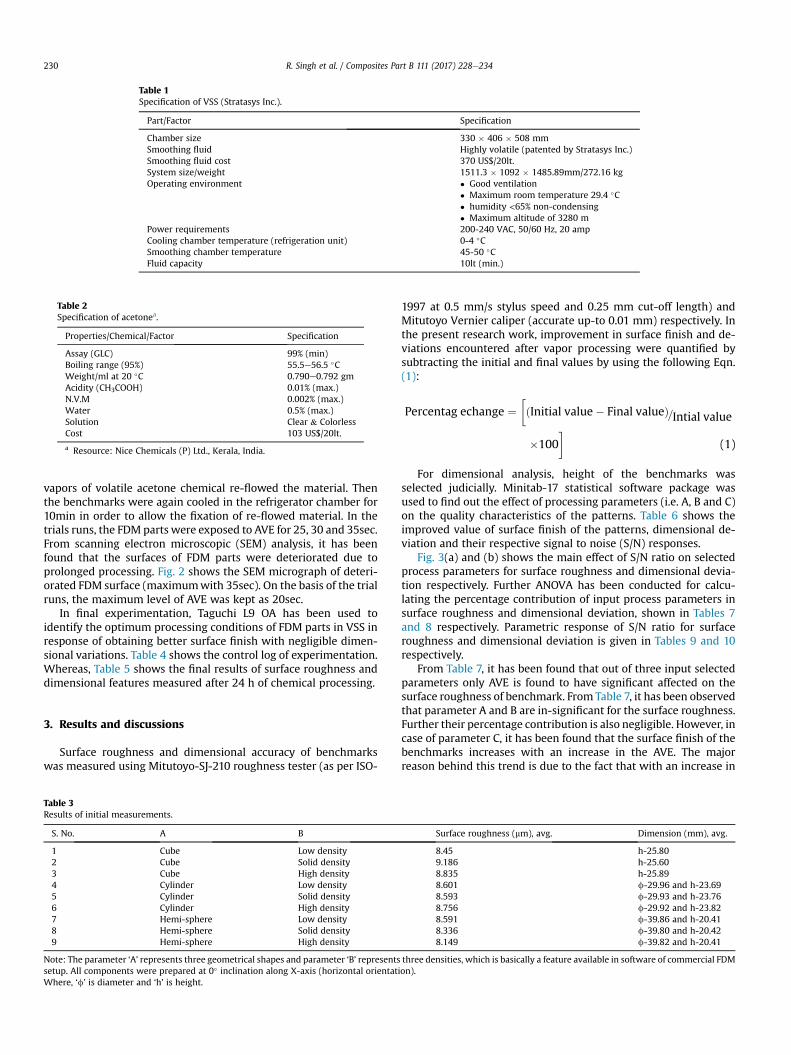
Table 1Specification of VSS (Stratasys Inc.).
Part/Factor Specification
Chamber size 330 � 406 � 508 mmSmoothing fluid Highly volatile (patented by Stratasys Inc.)Smoothing fluid cost 370 US$/20lt.System size/weight 1511.3 � 1092 � 1485.89mm/272.16 kgOperating environment � Good ventilation
� Maximum room temperature 29.4 �C� humidity <65% non-condensing� Maximum altitude of 3280 m
Power requirements 200-240 VAC, 50/60 Hz, 20 ampCooling chamber temperature (refrigeration unit) 0-4 �CSmoothing chamber temperature 45-50 �CFluid capacity 10lt (min.)
Table 2Specification of acetonea.
Properties/Chemical/Factor Specification
Assay (GLC) 99% (min)Boiling range (95%) 55.5e56.5 �CWeight/ml at 20 �C 0.790e0.792 gmAcidity (CH3COOH) 0.01% (max.)N.V.M 0.002% (max.)Water 0.5% (max.)Solution Clear & ColorlessCost 103 US$/20lt.
a Resource: Nice Chemicals (P) Ltd., Kerala, India.
R. Singh et al. / Composites Part B 111 (2017) 228e234230
vapors of volatile acetone chemical re-flowed the material. Thenthe benchmarks were again cooled in the refrigerator chamber for10min in order to allow the fixation of re-flowed material. In thetrials runs, the FDM parts were exposed to AVE for 25, 30 and 35sec.From scanning electron microscopic (SEM) analysis, it has beenfound that the surfaces of FDM parts were deteriorated due toprolonged processing. Fig. 2 shows the SEM micrograph of deteri-orated FDM surface (maximumwith 35sec). On the basis of the trialruns, the maximum level of AVE was kept as 20sec.
In final experimentation, Taguchi L9 OA has been used toidentify the optimum processing conditions of FDM parts in VSS inresponse of obtaining better surface finish with negligible dimen-sional variations. Table 4 shows the control log of experimentation.Whereas, Table 5 shows the final results of surface roughness anddimensional features measured after 24 h of chemical processing.
3. Results and discussions
Surface roughness and dimensional accuracy of benchmarkswas measured using Mitutoyo-SJ-210 roughness tester (as per ISO-
Table 3Results of initial measurements.
S. No. A B
1 Cube Low density2 Cube Solid density3 Cube High density4 Cylinder Low density5 Cylinder Solid density6 Cylinder High density7 Hemi-sphere Low density8 Hemi-sphere Solid density9 Hemi-sphere High density
Note: The parameter ‘A’ represents three geometrical shapes and parameter ‘B’ representssetup. All components were prepared at 0� inclination along X-axis (horizontal orientatWhere, ‘f’ is diameter and ‘h’ is height.
1997 at 0.5 mm/s stylus speed and 0.25 mm cut-off length) andMitutoyo Vernier caliper (accurate up-to 0.01 mm) respectively. Inthe present research work, improvement in surface finish and de-viations encountered after vapor processing were quantified bysubtracting the initial and final values by using the following Eqn.(1):
Percentag echange ¼�ðInitial value� Final valueÞ=Intial value
�100�
(1)
For dimensional analysis, height of the benchmarks wasselected judicially. Minitab-17 statistical software package wasused to find out the effect of processing parameters (i.e. A, B and C)on the quality characteristics of the patterns. Table 6 shows theimproved value of surface finish of the patterns, dimensional de-viation and their respective signal to noise (S/N) responses.
Fig. 3(a) and (b) shows the main effect of S/N ratio on selectedprocess parameters for surface roughness and dimensional devia-tion respectively. Further ANOVA has been conducted for calcu-lating the percentage contribution of input process parameters insurface roughness and dimensional deviation, shown in Tables 7and 8 respectively. Parametric response of S/N ratio for surfaceroughness and dimensional deviation is given in Tables 9 and 10respectively.
From Table 7, it has been found that out of three input selectedparameters only AVE is found to have significant affected on thesurface roughness of benchmark. From Table 7, it has been observedthat parameter A and B are in-significant for the surface roughness.Further their percentage contribution is also negligible. However, incase of parameter C, it has been found that the surface finish of thebenchmarks increases with an increase in the AVE. The majorreason behind this trend is due to the fact that with an increase in
Surface roughness (mm), avg. Dimension (mm), avg.
8.45 h-25.809.186 h-25.608.835 h-25.898.601 f-29.96 and h-23.698.593 f-29.93 and h-23.768.756 f-29.92 and h-23.828.591 f-39.86 and h-20.418.336 f-39.80 and h-20.428.149 f-39.82 and h-20.41
three densities, which is basically a feature available in software of commercial FDMion).

Fig. 2. (a) SEM micrograph of FDM part exposed to 25 (b) 30 and (c) 35sec.
Table 4Control log of experimentation.
S. No. A B Chemical exposure time (C),sec.
1 Cube Low density 102 Cube Solid density 153 Cube High density 204 Cylinder Low density 155 Cylinder Solid density 206 Cylinder High density 107 Hemi-sphere Low density 208 Hemi-sphere Solid density 109 Hemi-sphere High density 15
R. Singh et al. / Composites Part B 111 (2017) 228e234 231
the AVE cycle time sufficient time was available for the re-flowmechanism. The SEM analysis (with transverse view) of thefinished FDM benchmark component (as shown in Fig. 4) showsthat exposing of FDM parts to AVE in VSS have re-flowed the
Table 5Results of final measurements.
S. No. A B C
1 Cube Low density 102 Cube Solid density 153 Cube High density 204 Cylinder Low density 155 Cylinder Solid density 206 Cylinder High density 107 Hemi-sphere Low density 208 Hemi-sphere Solid density 109 Hemi-sphere High density 15
Where, ‘f’ is diameter and ‘h’ is height.
Table 6Improved value of surface roughness, dimensional deviation and their respective S/N res
S. No. Improvement in surface roughness (%) S/N ra
1 95.38 39.582 97.93 39.813 99.20 39.934 97.90 39.815 99.19 39.926 97.25 39.757 99.06 39.918 96.28 39.679 97.91 39.81Overall mean of S/N ratio for surface roughness is 39.8050
material and resulted into the formation of a fine layer of on thesurface of FDM parts.
It can be seen from Fig. 4 that the thickness of re-flow layerincreases with AVE exposure time.With an increase in the AVE timethe depth of penetration also increased due to which more numberof layers started to reflow hence the thickness of re-flow layerincreased (as shown in Fig. 4). However, the prolonged exposuretime may have some affect the mechanical properties (like:dimensional accuracy, tensile strength, compressive strength,elongation, hardness, etc.) which are yet to explore.
The optimized settings for surface roughness of vapor smooth-ened FDM benchmark parts are: A > cylinder, B > high density andC > 20sec. However, in case of dimensional deviation, none ofparameter was found to have significant affect (as given in Table 8)on the geometrical features of the benchmark components. Theoptimized settings for dimensional deviation are: A > hemi-sphere,B > solid density and C > 10sec.
Hence, the optimum condition of input process parameters for
Surface roughness (mm), avg. Dimension (mm), avg.
0.39 h-25.750.19 h-25.530.07 h-25.450.18 f-29.82 and h-23.630.069 f-29.82 and h-23.710.24 f-29.83 and h-23.760.08 f-39.77 and h-20.300.31 f-39.76 and h-20.310.17 f-39.77 and h-20.25
ponse.
tio, db Dimensional deviation (%) S/N ratio, db
0.19 14.420.27 11.371.69 �4.550.46 6.740.36 8.870.30 10.450.22 13.150.10 20.000.12 18.41Overall mean of S/N ratio for dimensional deviation is10.98

Fig. 3. (a) Main effect of S/N ratio on input process parameters for surface roughness (b) for dimensional deviation.
Table 7ANOVA for surface roughness.
Source Degree of freedom Sum of square Variance F-value P-value Percentage contribution (%) Significance (Yes/No)
A 2 0.004594 0.002297 1.09 0.479 4.13 NoB 2 0.005514 0.002757 1.31 0.433 4.95 NoC 2 0.096863 0.048431 22.98 0.042 87.11 YesError 2 0.004216 0.002108 3.79Total 8 0.111186
Table 8ANOVA for dimensional deviation.
Source Degree of freedom Sum of square Variance F-value P-value Percentage contribution (%) Significance (Yes/No)
A 2 177.00 88.50 2.70 0.27 42.39 NoB 2 43.22 21.61 0.66 0.61 10.35 NoC 2 131.64 65.82 2.01 0.34 31.49 NoError 2 65.60 32.80 15.71Total 8 417.46
Table 9Response table of S/N ratio for surface roughness.
Level A B C
1 39.78 39.77 39.672 39.83a 39.81 39.823 39.80 39.83a 39.93a
Delta 0.06 0.06 0.25Rank 3 2 1
a Indicating the optimum response.
Table 10Response table of S/N ratio for dimensional deviation.
Level A B C
1 7.08 11.44 14.962 8.69 13.42a 12.178a
3 17.189a 8..11 5.83Delta 10.11 5.31 9.14Rank 1 3 2
a Indicating the optimum response.
R. Singh et al. / Composites Part B 111 (2017) 228e234232
surface roughness is A2B3C3. The theoretical value of ‘h’ under theoptimum conditions, denoted by ‘hopt’ could be calculated fromfollowing Eqn. (2):
hopt ¼ mþ ðmA2 �mÞ þ ðmB3 �mÞ þ ðmC3 �mÞ ¼ 39:98db
(2)
Where m is the overall mean of S/N data (refer Table 6), mA2 isthe mean of S/N data for factor A at level 2 andmB3 is the mean of S/N data for factor B at level 3, etc (refer Table 9).
The corresponding value of surface roughness is given byfollowing Eqn. (3):
y2opt ¼ 1.10�hopt
=
10 (3)
And, yopt ¼ 0.010 m (predicted value).A confirmatory experiment was performed at the optimized
setting which resulted into surface roughness as 0.01 mm. Fig. 5shows roughness profile along with the SEM micrograph takenfor confirmatory experiment prior and after vapor smoothening. InFig. 5, the stair-case gap between two adjacent layers has beenfilled upon its chemical exposure due to the re-flow mechanism.This ensured the sensitivity of the ABS-P400 material towardsacetone fluid. Presently, the processing parameter of VSS was

Fig. 4. (a) SEM micrographs of FDM part processed for 10 (b) 15 and (c) 20sec.
Fig. 5. Roughness profile before vapor processing (a) after vapor processing (b).
R. Singh et al. / Composites Part B 111 (2017) 228e234 233
selected so that the re-flow of the material is just limited to thesurface of the benchmarks.
4. Conclusions
From the present research work following conclusions may bedrawn:
In this paper a chemical treatment of FDM patterns has been
carried out for improving their surface finish. The results of presentstudy highlighted that VSS and FDM patterns has been successfullycoupled and quality characteristics concerned to surface finish hasbeen improved to nano-level without affecting the dimensionalfeatures. The experimental study was conducted for finding theoptimum processing condition in-terms of shape of geometry, FDMsystem density and chemical exposure cycle. ANOVA highlightedthat only chemical exposure cycle has significantly affected the

R. Singh et al. / Composites Part B 111 (2017) 228e234234
surface finish of the patterns. Profilometer measurements made in-case of confirmatory experimentation showed the decrease inroughness profile of the patterns after their chemical treatment.The SEM micrographs highlighted the re-flow of the ABS materialresulted into formation of thin layer on the surface which improvedthe aesthetic look of the benchmarks. Further, the S/N responsehighlighted the negligible change in the dimensional features of thepatterns exposed to AVE.
Results of the present study explored the benefits of VSS forFDM parts to be used as either sacrificial pattern in investmentcasting process, and rapid manufacturing of innovative materialsand structures [23�36]. Further, the use of an alternative volatilefluid like acetone has effectively reduced the processing cost of VSS.Confirmatory experimentation showed a very good agreementbetween the predicted and experimental value.
Acknowledgements
The authors are thankful to All India Council for Technical Ed-ucation (NCP grant) for financial support.
References
[1] Boschetto A, Giordano V, Veniali F. Int J Adv Manuf Technol 2012;61:945e56.[2] Gebhardt A. Rapid prototyping. Hanser, Munich. 2003.[3] Hopkinson N, Hague R, Dickens P. Rapid manufacturing an industrial revo-
lution for the digital age. Chichester, West Sussex: John Wiley & Sons; 2005.[4] Wholers T. Wohlers report 2006: rapid prototyping & manufacturing state of
the industry annual worldwide progress report. Wohlers Associates, Inc. FortCollins, CO; 2006.
[5] Wohlers T. Wohlers report 2012: executive summary. Fort Collins, CO:Wohlers Associates, Inc; 2012.
[6] Boschetto A, Giordano V, Veniali F. Rapid Prototyp J 2013;19(4):240e52.[7] Chua CK, Leong KF, Lim CS. Rapid prototyping: principles and applications.
third ed. Singapore: World Scientific; 2010.[8] Ingole DS, Kuthe AM, Thakare SB, Talankar AS. Rapid Prototyp J 2009;15(4):
280e90.[9] Ivanova O, Williams C, Campbell T. Rapid Prototyp J 2013;19(5):353e64.
[10] Lee BH, Abdullah J, Khan ZA. J Material Process Technol 2005;169:54e61.[11] Huang X, Ye C, Wu S, Guo K, Mo J. Int J Adv Manuf Technol 2009;42:1074e81.[12] Pandey PM, Reddy NV, Dhande SG. Int J Mach Tools Manuf 2003;43(1):61e71.[13] Galantucci LM, Lavecchia F, Percoco G. CIRP Annals-Manufacturing Technol
2000;59(1):247e50.[14] Vasudevarao B, Natarajan DP, Henderson M. Sensitivity of RP surface finish to
process parameter variation. Austin, USA. In: Proceedings of solid free formfabrication; 2000. p. 252e8.
[15] Anitha R, Arunachalam S, Radhakrishnan P. J Material Process Technol2001;118:385e8.
[16] Ahn DK, Kim H, Lee S. J Mater Process Technol 2009;209:664e71.[17] Campbell RI, Martorelli M, Lee HS. Computer-Aided Des 2002;34:717e25.[18] Anoop KS, Ohdar RK, Mahapatra SS. Mater Des 2009;30(10):4243e52.[19] Ippolito R, Iuliano L, Gatto A. CIRP Annals-Manufacturing Technol 1995;44(1):
157e60.[20] Pennington RC, Hoekstra NL, Newcomer JL. Proceedings of the institution of
mechanical engineers, Part E. J Process Mech Eng 2005;219(1):89e92.[21] Thrimurthulu K, Pandey PM, Reddy NV. Int J Mach Tools Manuf 2004;44(6):
585e94.[22] Zinniel RL. Vapor smoothing surface finishing system. U.S. Patent No. 8075300
B2. 2011.[23] Singh R, Singh S, Fraternali F-. Development of in-house composite wire based
feed stock filaments of fused deposition modelling for wear-resistant mate-rials and structures. Composites. Part B. Engineering 2016;98:244e9.
[24] Singh R, Kumar R, Feo L, Fraternali F. Friction welding of dissimilar plastic/polymer materials with metal powder reinforcement. Compos Part B, Eng2016;101:77e86.
[25] Fraternali F, Farina I, Polzone C, Pagliuca E, Feo L. On the use of R-PET strips forthe reinforcement of cement mortars Composites. Part B. Engineering2013;46:207e10.
[26] Farina I, Fabbrocino F, Carpentieri G, Modano M, Amendola A, Goodall R, et al.On the reinforcement of cement mortars through 3D printed polymeric andmetallic fibers. Compos Part B, Eng 2016;90:76e85.
[27] Farina I, Fabbrocino F, Colangelo F, Feo L, Fraternali F. Surface roughness ef-fects on the reinforcement of cement mortars through 3D printed metallicfibers. Compos Part B, Eng 2016;99:305e11.
[28] Fabbrocino F, Farina I, Amendola A, Feo L, Fraternali F. Optimal design andadditive manufacturing of novel reinforcing elements for composite materials,ECCOMAS Congress 2016 e European Congress on Computational Methods inApplied Sciences and Engineering, 5e10 JUNE 2016 Crete Island, Greece, No.4544 (16 pages).
[29] Schmidt B, Fraternali F. Universal formulae for the limiting elastic energy ofmembrane networks. J Mech Phys Solids 2012;60:172e80.
[30] Fraternali F. Free discontinuity finite element models in two-dimensions forin-plane crack problems. Theor Appl Fract Mech 2007;47:274e82. 2007.
[31] Fraternali F, Reddy JN. A penalty model for the analysis of laminated com-posite shells. Int J Solids Struct 1993;30:3337e55.
[32] Amendola A, Nava EH, Goodall R, Todd I, Skelton RE, Fraternali F. On theadditive manufacturing and testing of tensegrity structures. Compos Struct2015;131:66e71.
[33] Amendola A, Smith CJ, Goodall R, Auricchio F, Feo L, Benzoni G, et al. Exper-imental response of additively manufactured metallic pentamode materialsconfined between stiffening plates. Compos Struct 2016;142:254e62.
[34] Amendola A, Fabbrocino F, Feo L, Fraternali F. Dependence of the mechanicalproperties of pentamode materials on the lattice microstructure, ECCOMASCongress 2016 e European Congress on Computational Methods in AppliedSciences and Engineering, 5e10 JUNE 2016 Crete Island, Greece, No. 6004 (17pages).
[35] Amendola A, Carpentieri G, Feo L, Fraternali F. Bending dominated response oflayered mechanical metamaterials alternating pentamode lattices andconfinement plates. Online first Compos Struct 2016;157:71e7.
[36] Fabbrocino F, Amendola A, Benzoni G, Fraternali F. Seismic application ofpentamode lattices. Ingegneria Sismica/International J Earthq Eng 2016;1e2:62e71. ISSN: 0393-1420.