composite slabs stephen hicks - eurocodeseurocodes.jrc.ec.europa.eu/doc/ws2008/en1994_5_hic… ·...
TRANSCRIPT
Brussels, 18-20 February 2008 – Dissemination of information workshop 1
Background and ApplicationsEUROCODES
EN 1994 - Eurocode 4: Design of composite steel and concrete structures
Composite Slabs
Stephen Hicks

Brussels, 18-20 February 2008 – Dissemination of information workshop 2
EUROCODESBackground and Applications Composite slabs
Concrete cast in situWelded mesh reinforcement for crack control, transverse load distribution and fire resistance
Headed stud connectors for shear connection to the composite beam and, when required, end anchorage to the slab

Brussels, 18-20 February 2008 – Dissemination of information workshop 3
EUROCODESBackground and Applications
Through-deck welding of headed stud shear connectors

Brussels, 18-20 February 2008 – Dissemination of information workshop 4
EUROCODESBackground and Applications
Conventional composite construction

Brussels, 18-20 February 2008 – Dissemination of information workshop 5
EUROCODESBackground and Applications Benefits of composite beams
• Bending resistance increased by a factor of 1.5 to 2.5
• Stiffness increased by a factor of 3 to 4.5
• Steel weight reduced by typically 30 to 50%
• Reduction in beam depth (span:depth ≈ 25)
• Lightweight construction
Brussels, 18-20 February 2008 – Dissemination of information workshop 6
EUROCODESBackground and Applications Benefits of composite slabs
• Profiled steel sheeting acts as a safe working platform and permanent formwork.
• Unpropped construction may be achieved.
• Sheeting can stabilise beams during construction.
• Sheeting can provide all, or part, of the main tension reinforcement to the slab.
Brussels, 18-20 February 2008 – Dissemination of information workshop 7
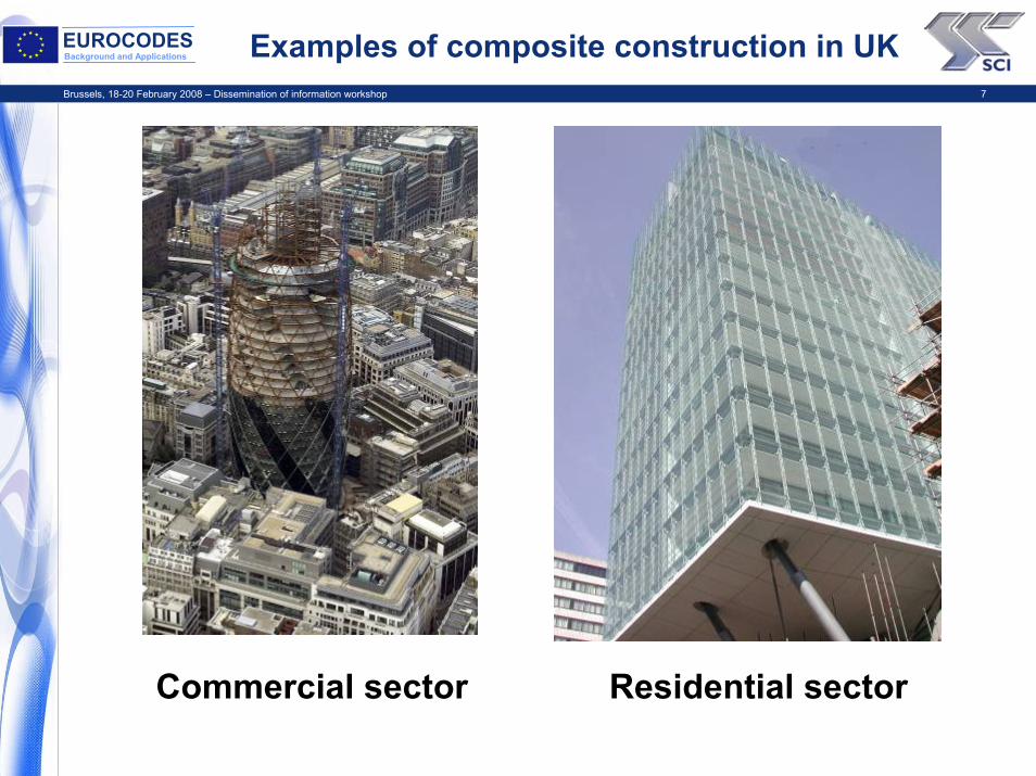
EUROCODESBackground and Applications Examples of composite construction in UK
Commercial sector Residential sector
Brussels, 18-20 February 2008 – Dissemination of information workshop 8
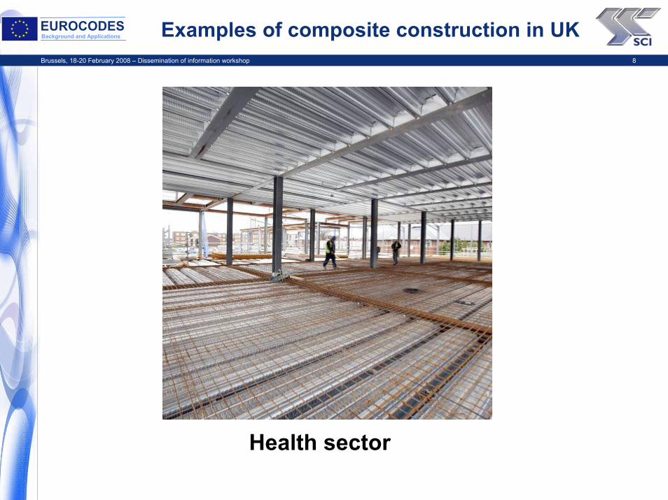
EUROCODESBackground and Applications Examples of composite construction in UK
Health sector
Brussels, 18-20 February 2008 – Dissemination of information workshop 9
EUROCODESBackground and Applications
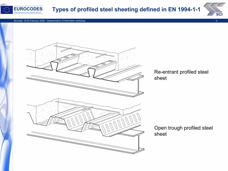
Types of profiled steel sheeting defined in EN 1994-1-1
Re-entrant profiled steel sheet
Open trough profiled steel sheet

Brussels, 18-20 February 2008 – Dissemination of information workshop 10
EUROCODESBackground and Applications
Practical examples of open trough and re-entrant profiled steel sheets used for composite slabs
Cover width: 1000
Multideck 60
323 mm
9 mm
60 mm
15 mm
Cover width: 600300 mm
60 mm ComFlor 60
207 mm
58 mm Confraplus 60
Cover width: 1035
183 mm
73 mm Cofrastra 70
Cover width: 732
Cover width: 900
Multideck 80
300 mm
9 mm
80.5 mm
15 mm
80 mm
180 mm 120 mm
145 mm
70 mm ComFlor 80
Cover width: 600
Cover width: 750
Cofrastra 40
150 mm
40 mm
152.5 mm
51 mm
Cover width : 610
Super Holorib 51
Brussels, 18-20 February 2008 – Dissemination of information workshop 11
EUROCODESBackground and Applications
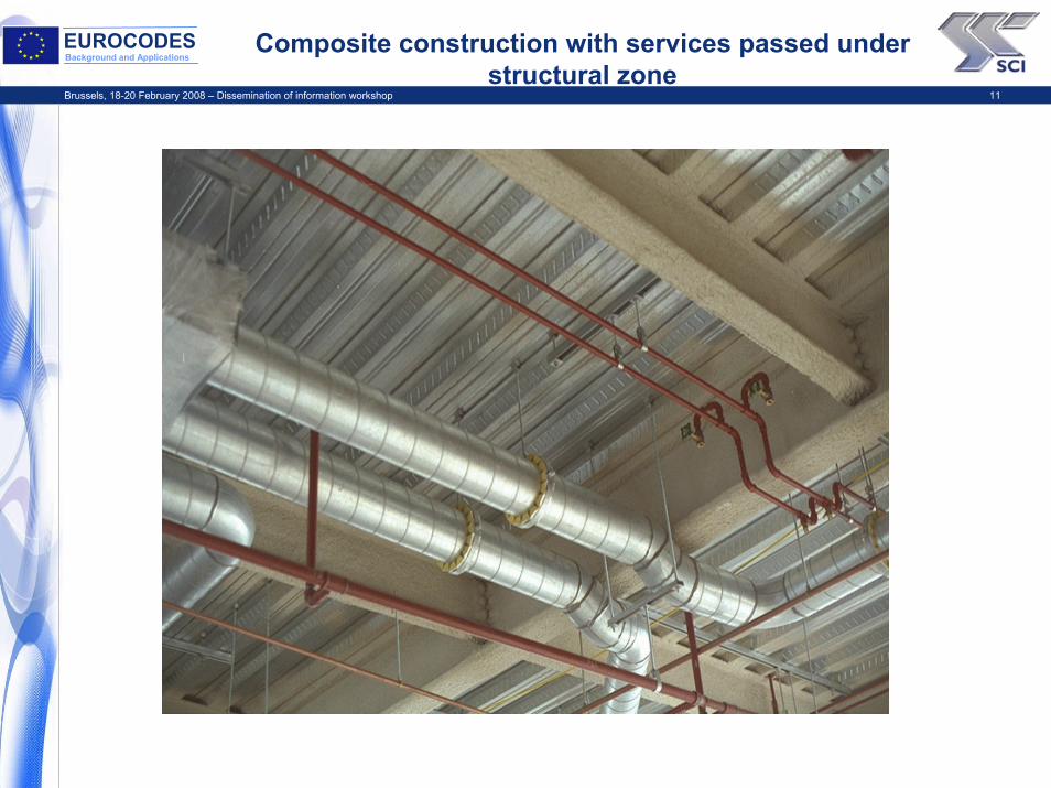
Composite construction with services passed under structural zone

Brussels, 18-20 February 2008 – Dissemination of information workshop 12
EUROCODESBackground and Applications Examples of fixings for ceilings and services
Wedge attachment Clip attachment
Alternative wedge attachment

Brussels, 18-20 February 2008 – Dissemination of information workshop 13
EUROCODESBackground and Applications EN 1994-1-1 detailing requirements
Scope limited to sheets with narrowly spaced ribs : br / bs ≤ 0,6
Slab thicknessWhen slab is acting compositely with beam or is used as a diaphragm:h ≥ 90 mm & hc ≥ 90 mm
When slab is not acting compositely with beam or has no stabilizing function:h ≥ 80 mm & hc ≥ 40 mm
Reinforcement ≥ 80 mm²/m in both directions
Spacing of reinforcement barss ≤ 2h & 350 mm
Maximum aggregate sizedg ≤ 0,4 hc, b0 / 3 and 31,5 mm
o
o
b b r
r
b
b
s
s
Re-entrant trough profile
b b
b b
b b
p
p
p
h
h
h
h
h
h
c
c
h1/2
Open trough profile
Brussels, 18-20 February 2008 – Dissemination of information workshop 14
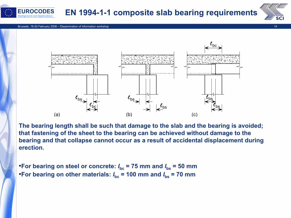
EUROCODESBackground and Applications EN 1994-1-1 composite slab bearing requirements
The bearing length shall be such that damage to the slab and the bearing is avoided; that fastening of the sheet to the bearing can be achieved without damage to the bearing and that collapse cannot occur as a result of accidental displacement during erection.
•For bearing on steel or concrete: lbc = 75 mm and lbs = 50 mm•For bearing on other materials: lbc = 100 mm and lbs = 70 mm
bs bs bs
bc
bc
(a) (b)bs bs
(c)
Brussels, 18-20 February 2008 – Dissemination of information workshop 15
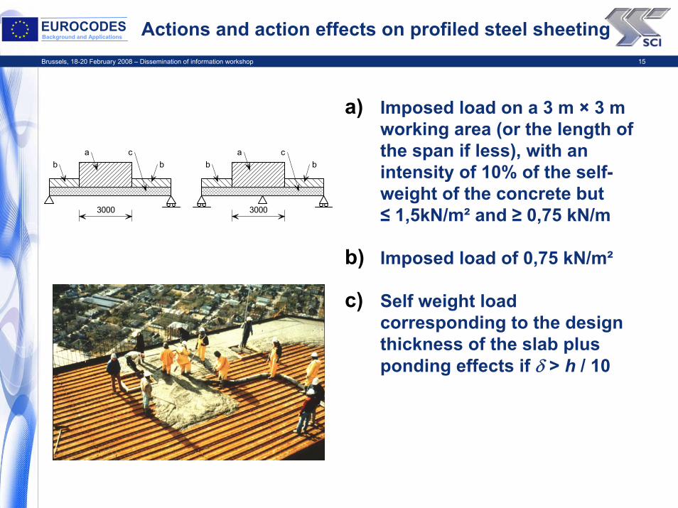
EUROCODESBackground and Applications Actions and action effects on profiled steel sheeting
a) Imposed load on a 3 m × 3 m working area (or the length of the span if less), with an intensity of 10% of the self-weight of the concrete but ≤ 1,5kN/m² and ≥ 0,75 kN/m
b) Imposed load of 0,75 kN/m²
c) Self weight load corresponding to the design thickness of the slab plus ponding effects if δ > h / 10
b b b b
3000 3000
a ac c
Brussels, 18-20 February 2008 – Dissemination of information workshop 16
EUROCODESBackground and Applications
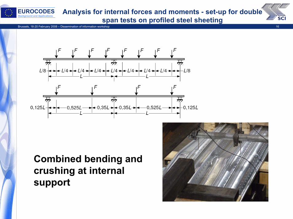
Analysis for internal forces and moments - set-up for double span tests on profiled steel sheeting
Combined bending and crushing at internal support
Brussels, 18-20 February 2008 – Dissemination of information workshop 17
EUROCODESBackground and Applications
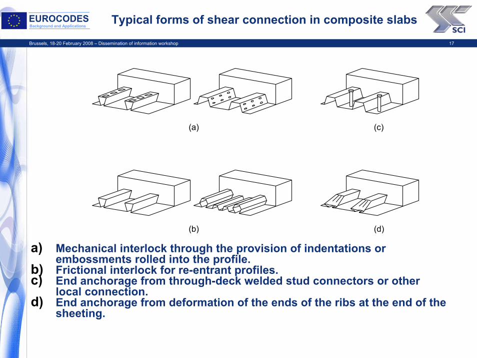
Typical forms of shear connection in composite slabs
(a) (c)
(b) (d)
a) Mechanical interlock through the provision of indentations or embossments rolled into the profile.
b) Frictional interlock for re-entrant profiles. c) End anchorage from through-deck welded stud connectors or other
local connection.d) End anchorage from deformation of the ends of the ribs at the end of the
sheeting.
Brussels, 18-20 February 2008 – Dissemination of information workshop 18
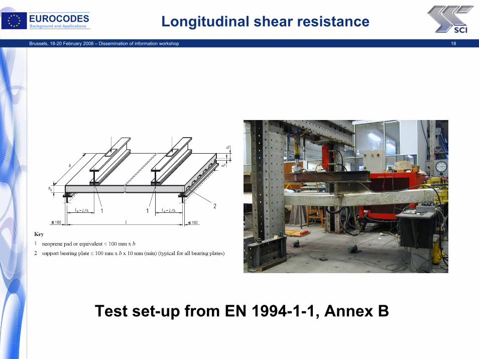
EUROCODESBackground and Applications Longitudinal shear resistance
Test set-up from EN 1994-1-1, Annex B

Brussels, 18-20 February 2008 – Dissemination of information workshop 19
EUROCODESBackground and Applications Classification of ductile or brittle behaviour
1. Brittle behaviouro m-k method
2. Ductile behaviour - failure load exceeds the load causing a recorded end slip of 0,1 mm by more than 10%o Partial connection methodo m-k method
LoadP(kN)
50
40
30
20
10
Slip atfirst end
Slip at second end
10 20 30 40 50
P/2 P/2
Deflection (mm)
δ
δ
1
2Load
F(kN)
F/2 F/2
Brussels, 18-20 February 2008 – Dissemination of information workshop 20
EUROCODESBackground and Applications
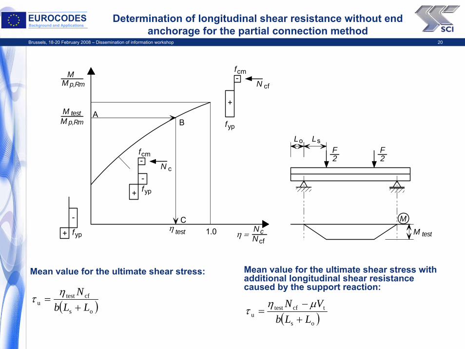
Mean value for the ultimate shear stress with additional longitudinal shear resistance caused by the support reaction:
Determination of longitudinal shear resistance without end anchorage for the partial connection method
-
-
-
-
+
+
+
f
f
f
f
f
yp
yp
yp
cm
cm
N
N
cf
cf
c
AB
C1.0
p,Rm
p,Rm
MM
test
test test
MM
ηη = cN
N
F2
F2
L L o s
MM
Mean value for the ultimate shear stress:
( )os
cftestu LLb
N+
=η
τ ( )os
tcftestu LLb
VN+
−=
μητ
Brussels, 18-20 February 2008 – Dissemination of information workshop 21
EUROCODESBackground and Applications Determination of design value for τu,Rd from tests
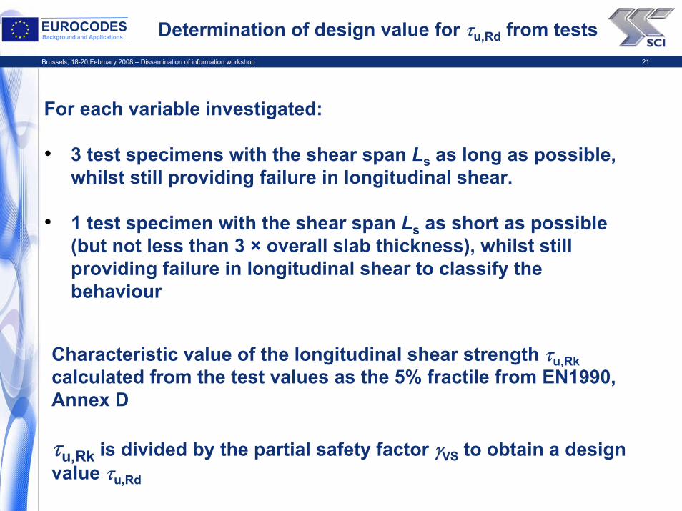
For each variable investigated:
• 3 test specimens with the shear span Ls as long as possible, whilst still providing failure in longitudinal shear.
• 1 test specimen with the shear span Ls as short as possible (but not less than 3 × overall slab thickness), whilst still providing failure in longitudinal shear to classify the behaviour
Characteristic value of the longitudinal shear strength τu,Rkcalculated from the test values as the 5% fractile from EN1990, Annex D
τu,Rk is divided by the partial safety factor γVS to obtain a design value τu,Rd
Brussels, 18-20 February 2008 – Dissemination of information workshop 22
EUROCODESBackground and Applications
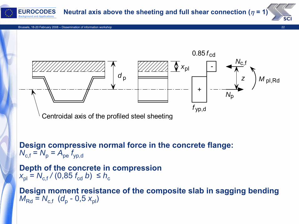
Neutral axis above the sheeting and full shear connection (η = 1)
Design compressive normal force in the concrete flange:Nc,f = Np = Ape fyp,d
Depth of the concrete in compression xpl = Nc,f / (0,85 fcd b) ≤ hc
Design moment resistance of the composite slab in sagging bending MRd = Nc,f (dp - 0,5 xpl)
d p
xpl
z
c,f
p
N
N
M pl,Rd
f
f
yp,d
cd0.85
+
-
Centroidal axis of the profiled steel sheeting

Brussels, 18-20 February 2008 – Dissemination of information workshop 23
EUROCODESBackground and Applications
Neutral axis within the sheeting and full shear connection (η = 1)
Design compressive normal force in the concrete flange: Nc,f = 0,85 fcd b hc
Reduced plastic moment resistance of the sheeting:
Lever arm:
Design moment resistance of the composite slab in sagging bending
MRd = Nc,f z + Mpr
p
c,fN
M
f
f
f
yp,d
yp,d
cd0.85
+
+
+
- - -
e e
Centroidal axis of the profiled steel sheetingPlastic neutral axis of the profiled steel sheeting
hcprz
+=
⎟⎟⎠
⎞⎜⎜⎝
⎛−=
dyp,pe
cfpapr 125,1
fANMM
( )dyp,pe
cfppc5,0
fANeeehhz −+−−=
Brussels, 18-20 February 2008 – Dissemination of information workshop 24
EUROCODESBackground and Applications
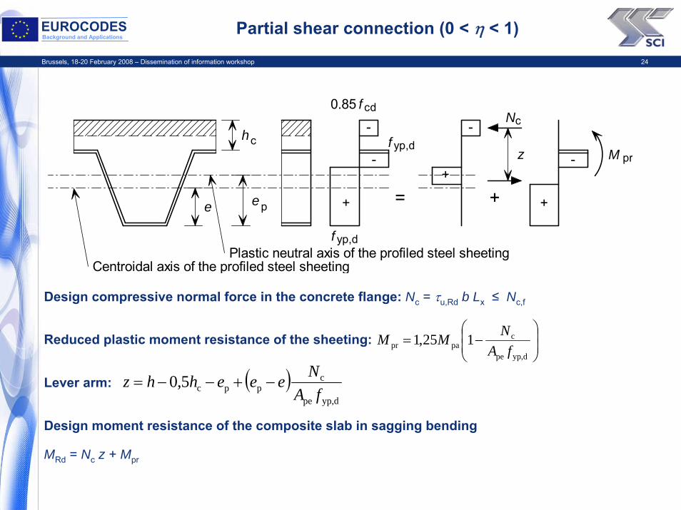
Partial shear connection (0 < η < 1)
Design compressive normal force in the concrete flange: Nc = τu,Rd b Lx ≤ Nc,f
Reduced plastic moment resistance of the sheeting:
Lever arm:
Design moment resistance of the composite slab in sagging bending
MRd = Nc z + Mpr
⎟⎟⎠
⎞⎜⎜⎝
⎛−=
dyp,pe
cpapr 125,1
fANMM
( )dyp,pe
cppc5,0
fANeeehhz −+−−=
p
N
M
f
f
f
yp,d
yp,d
cd0.85
+
+
+
- -
--
e e
Centroidal axis of the profiled steel sheetingPlastic neutral axis of the profiled steel sheeting
hcpr
+=
c
z

Brussels, 18-20 February 2008 – Dissemination of information workshop 25
EUROCODESBackground and Applications End anchorage
According to EN 1994-1-1, design resistance of a headed stud welded through the steel sheet used for end anchorage should be taken as the lesser of:
PRd kt
or
Ppb,Rd = kφ ddo t fyp,d
where PRd is the design resistance of a headed stud embedded in concrete, kt is a reduction factor for deck shape, ddo is the diameter of the weld collar (which may be taken as 1,1 times the shank diameter), t is the sheet thickness and kφ = 1 + a / ddo ≤ 6,0
d
f
f
yp
yp
/2
/2
d0
≥ 1.5 d0a d
Stud

Brussels, 18-20 February 2008 – Dissemination of information workshop 26
EUROCODESBackground and Applications
Variation of bending resistance along a span: uniform distributed load
M
M
pl,Rd
pl,p,RdM
Ve,Rdb u,Rdτ
L LLsf x
M Ed
L
q
L x
MRd with end anchorage
MRd without end anchorage
MRd
Mpa
MEd
Rdu,
Rdpb,
bPτ b
kP
Rdu,
tRd
τor whichever is the lesser

Brussels, 18-20 February 2008 – Dissemination of information workshop 27
EUROCODESBackground and Applications
Variation of bending resistance along a span: Point load
M
M
pl,Rd
pl,p,Rd
L LLsf x
M Ed
L
L x
M
FMRd without end anchorage
MEd
Mpa
MRd
Brussels, 18-20 February 2008 – Dissemination of information workshop 28
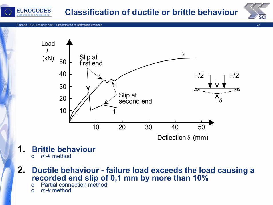
EUROCODESBackground and Applications Classification of ductile or brittle behaviour
1. Brittle behaviouro m-k method
2. Ductile behaviour - failure load exceeds the load causing a recorded end slip of 0,1 mm by more than 10%o Partial connection methodo m-k method
LoadP(kN)
50
40
30
20
10
Slip atfirst end
Slip at second end
10 20 30 40 50
P/2 P/2
Deflection (mm)
δ
δ
1
2Load
F(kN)
F/2 F/2
Brussels, 18-20 February 2008 – Dissemination of information workshop 29
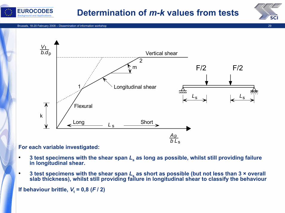
EUROCODESBackground and Applications Determination of m-k values from tests
For each variable investigated:
• 3 test specimens with the shear span Ls as long as possible, whilst still providing failure in longitudinal shear.
• 3 test specimens with the shear span Ls as short as possible (but not less than 3 × overall slab thickness), whilst still providing failure in longitudinal shear to classify the behaviour
If behaviour brittle, Vt = 0,8 (F / 2)
m
Vertical shear
Longitudinal shear1
2
Vb.d
tp
k
Flexural
A b L
L
ps
s s
sLong Short
L L
F/2 F/2
Brussels, 18-20 February 2008 – Dissemination of information workshop 30
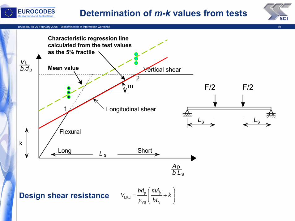
EUROCODESBackground and Applications
Characteristic regression line calculated from the test values as the 5% fractile
Determination of m-k values from tests
Design shear resistance
m
Vertical shear
Longitudinal shear1
2
Vb.d
tp
k
Flexural
A b L
L
ps
s s
sLong Short
L L
Mean value
⎟⎟⎠
⎞⎜⎜⎝
⎛+= k
bLmAbd
Vs
p
VS
pRdl, γ
F/2 F/2
Brussels, 18-20 February 2008 – Dissemination of information workshop 31
EUROCODESBackground and Applications Disadvantages of m-k method
• The results contain all the influencing parameters, but are impossible to separate from one another.
• Methodology is not based on a mechanical model and is therefore less flexible than the partial connection approach (contribution from end anchorage and reinforcement need to be evaluated from additional tests).
• Other loading arrangements that differ from the test loading can be problematical.
Brussels, 18-20 February 2008 – Dissemination of information workshop 32
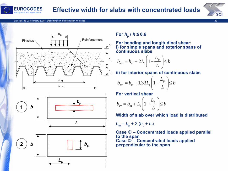
EUROCODESBackground and Applications Effective width for slabs with concentrated loads
For hp / h ≤ 0,6
For bending and longitudinal shear:i) for simple spans and exterior spans of continuous slabs
ii) for interior spans of continuous slabs
For vertical shear
Width of slab over which load is distributed
bm = bp + 2 (hc + hf)
Case – Concentrated loads applied parallel to the spanCase – Concentrated loads applied perpendicular to the span
b p
Finishes Reinforcement
b
b
hc
m
cm
h
h f
p
L
bbp
Lp
b bp
1
2
bLL
Lbb p ≤⎟⎟⎠
⎞⎜⎜⎝
⎛−+= 12 pmem
bLL
Lbb p ≤⎟⎟⎠
⎞⎜⎜⎝
⎛−+= 133,1 pmem
bLL
Lbb p ≤⎟⎟⎠
⎞⎜⎜⎝
⎛−+= 1pmev
Brussels, 18-20 February 2008 – Dissemination of information workshop 33
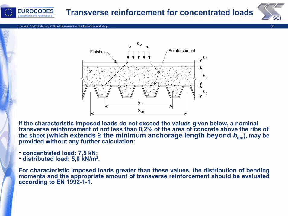
EUROCODESBackground and Applications Transverse reinforcement for concentrated loads
If the characteristic imposed loads do not exceed the values given below, a nominal transverse reinforcement of not less than 0,2% of the area of concrete above the ribs of the sheet (which extends ≥ the minimum anchorage length beyond bem), may be provided without any further calculation:
• concentrated load: 7,5 kN;• distributed load: 5,0 kN/m².
For characteristic imposed loads greater than these values, the distribution of bending moments and the appropriate amount of transverse reinforcement should be evaluated according to EN 1992-1-1.
b p
Finishes Reinforcement
b
b
hc
m
cm
h
h f
p
Brussels, 18-20 February 2008 – Dissemination of information workshop 34
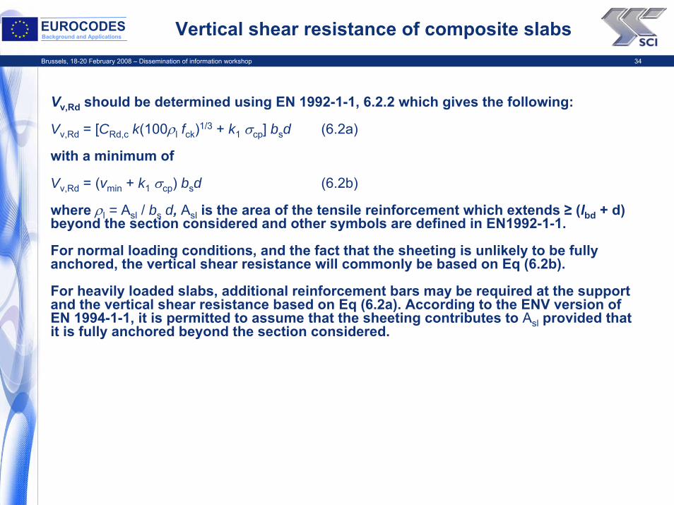
EUROCODESBackground and Applications Vertical shear resistance of composite slabs
Vv,Rd should be determined using EN 1992-1-1, 6.2.2 which gives the following:
Vv,Rd = [CRd,c k(100ρl fck)1/3 + k1 σcp] bsd (6.2a)
with a minimum of
Vv,Rd = (vmin + k1 σcp) bsd (6.2b)
where ρl = Asl / bs d, Asl is the area of the tensile reinforcement which extends ≥ (lbd + d) beyond the section considered and other symbols are defined in EN1992-1-1.
For normal loading conditions, and the fact that the sheeting is unlikely to be fully anchored, the vertical shear resistance will commonly be based on Eq (6.2b).
For heavily loaded slabs, additional reinforcement bars may be required at the support and the vertical shear resistance based on Eq (6.2a). According to the ENV version of EN 1994-1-1, it is permitted to assume that the sheeting contributes to Asl provided that it is fully anchored beyond the section considered.
Brussels, 18-20 February 2008 – Dissemination of information workshop 35
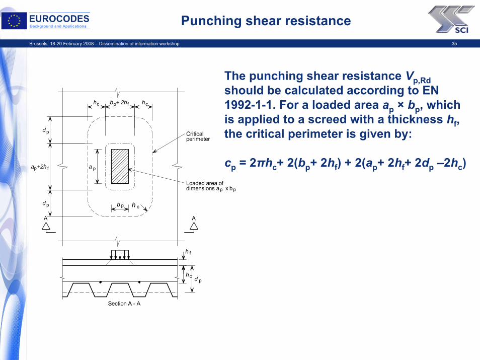
EUROCODESBackground and Applications Punching shear resistance
c
c
c c
p
p
p
p p
Section A - A
d
d
AA
p
p
p
d
Loaded area ofdimensions a x b
h f
h
hh
h
Criticalperimeter
b + 2h p f
f
b
a +2h a
The punching shear resistance Vp,Rdshould be calculated according to EN 1992-1-1. For a loaded area ap × bp, which is applied to a screed with a thickness hf, the critical perimeter is given by:
cp = 2πhc+ 2(bp+ 2hf) + 2(ap+ 2hf+ 2dp –2hc)
Brussels, 18-20 February 2008 – Dissemination of information workshop 36
EUROCODESBackground and Applications Serviceability limit states for composite slabs
Crack widthsFor continuous slabs that are designed as simply-supported, the minimum cross-sectional area of the anti-crack reinforcement within the depth hc should be:
• 0,2% of the cross-sectional area of the concrete above the ribs for unpropped construction• 0,4% of the cross-sectional area of the concrete above the ribs for propped construction.
The above amounts do not automatically ensure that wmax ≤ 0,3 mm as given in EN1992-1-1 for certain exposure classes.
If cracking needs to be controlled, the slab should be designed as continuous, and the crack widths in hogging moment regions evaluated according to EN 1992-1-1, 7.3.
Deflection
Deflections due to loading applied to the composite member should be calculated using elastic analysis, neglecting the effects of shrinkage.
For an internal span of a continuous slab, the deflection may be estimated using the following approximation:• the average value of the cracked and uncracked second moment of area may be taken.• for the concrete, an average value of the modular ratio for long-term and short-term effects may
be used.
For external, or simply supported spans, calculations of the deflection of the composite slab may be omitted if:
• the span/depth ratio of the slab does not exceed 20 for a simply-supported span and 26 for an external span of a continuous slab (corresponding to the lightly stressed concrete limits given in EN 1992-1-1; and
• the load causing an end slip of 0,5 mm in the tests on composite slabs exceeds 1,2 times the design service load.

Brussels, 18-20 February 2008 – Dissemination of information workshop 37
EUROCODESBackground and Applications Standard push test
150
250
250
150 150260
Cover 15P
PRk
Load
per
stu
d P
(kN)
Slip (mm)δδu
6 mm
Brussels, 18-20 February 2008 – Dissemination of information workshop 38
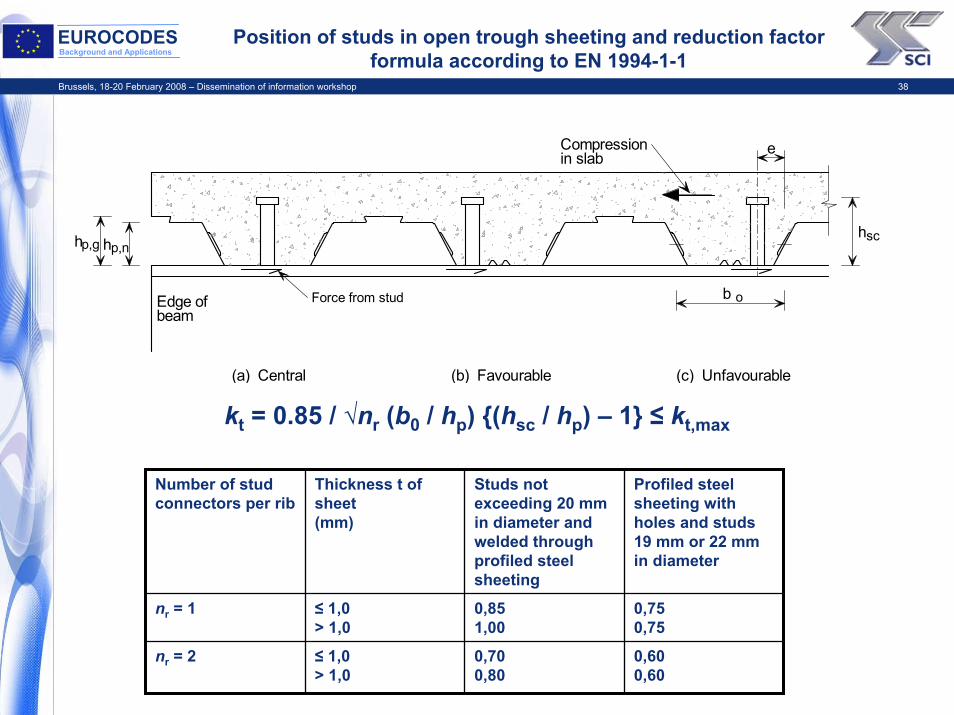
EUROCODESBackground and Applications
Position of studs in open trough sheeting and reduction factor formula according to EN 1994-1-1
b Edge ofbeam
p,g p,nh h h
e
sc
o
Compressionin slab
Force from stud
(a) Central (b) Favourable (c) Unfavourable
kt = 0.85 / √nr (b0 / hp) {(hsc / hp) – 1} ≤ kt,max
Number of stud connectors per rib
Thickness t of sheet(mm)
Studs not exceeding 20 mm in diameter and welded through profiled steel sheeting
Profiled steel sheeting with holes and studs 19 mm or 22 mm in diameter
nr = 1 ≤ 1,0> 1,0
0,851,00
0,750,75
nr = 2 ≤ 1,0> 1,0
0,700,80
0,600,60
Brussels, 18-20 February 2008 – Dissemination of information workshop 39
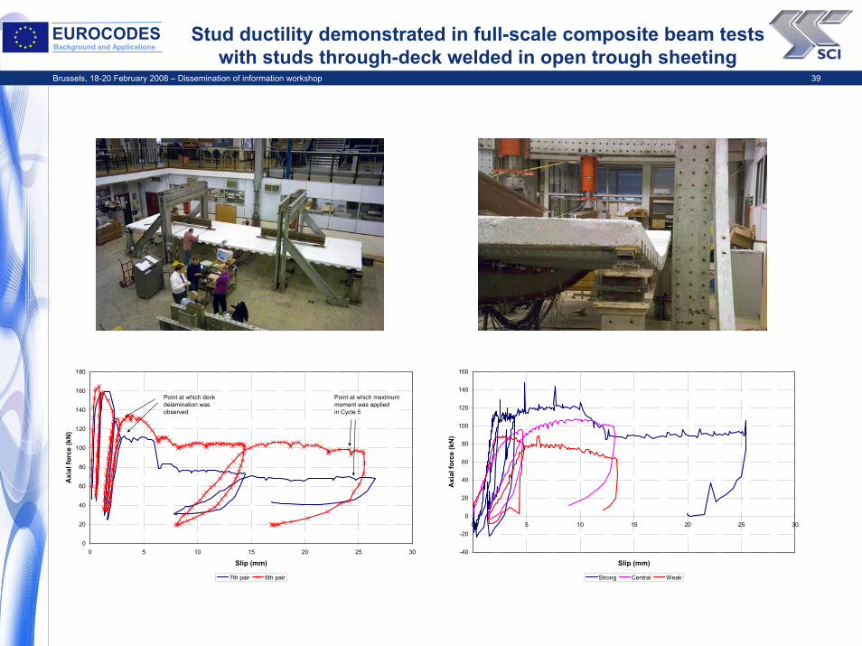
EUROCODESBackground and Applications
Stud ductility demonstrated in full-scale composite beam tests with studs through-deck welded in open trough sheeting
0
20
40
60
80
100
120
140
160
180
0 5 10 15 20 25 30
Slip (mm)
Axi
al fo
rce
(kN
)
7th pair 6th pair
Point at which maximummoment was appliedin Cycle 5
Point at which deck delamination wasobserved
-40
-20
0
20
40
60
80
100
120
140
160
0 5 10 15 20 25 30
Slip (mm)
Axi
al fo
rce
(kN
)
Strong Central Weak
Brussels, 18-20 February 2008 – Dissemination of information workshop 40
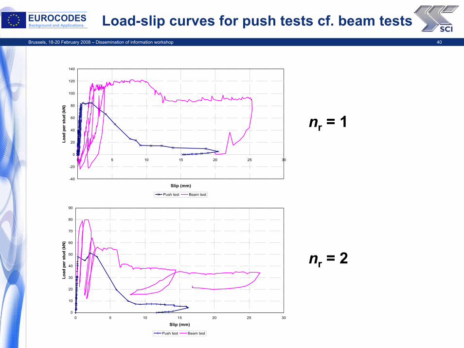
EUROCODESBackground and Applications Load-slip curves for push tests cf. beam tests
0
10
20
30
40
50
60
70
80
90
0 5 10 15 20 25 30
Slip (mm)
Load
per
stu
d (k
N)
Push test Beam test
-40
-20
0
20
40
60
80
100
120
140
0 5 10 15 20 25 30
Slip (mm)
Load
per
stu
d (k
N)
Push test Beam test
nr = 1
nr = 2
Brussels, 18-20 February 2008 – Dissemination of information workshop 41
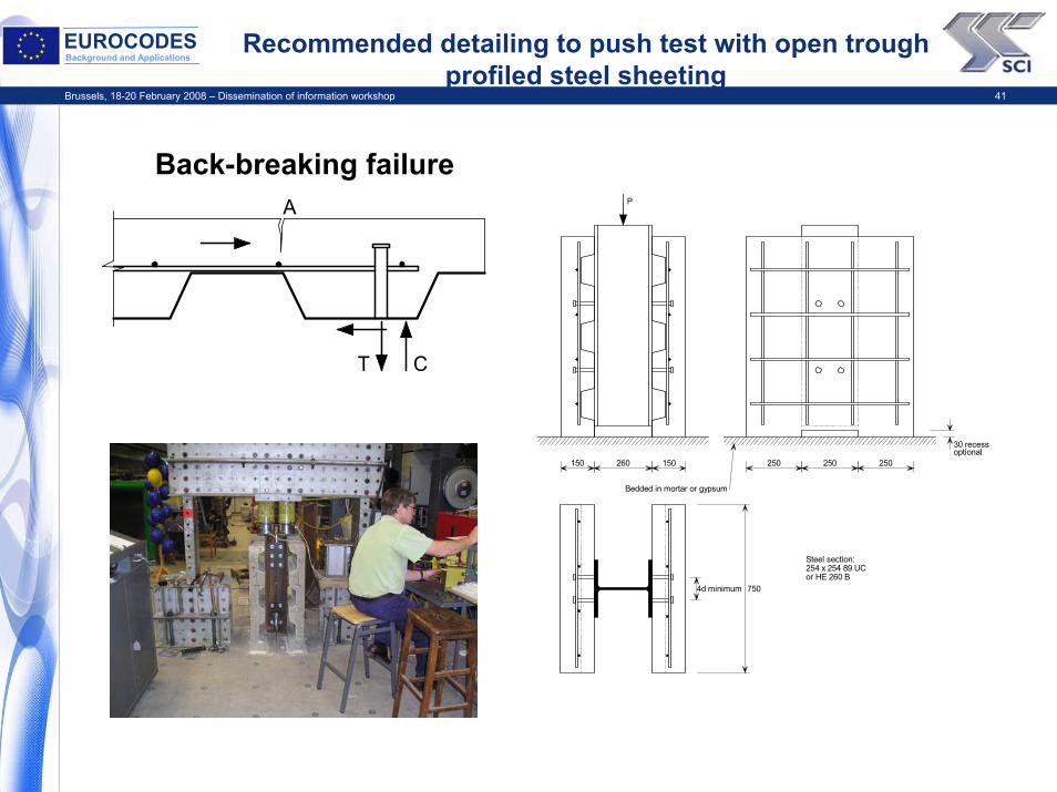
EUROCODESBackground and Applications
Recommended detailing to push test with open trough profiled steel sheeting
Back-breaking failure
150 150260
Bedded in mortar or gypsum
4d minimum 750
250250250
P
Steel section:254 x 254 89 UC or HE 260 B
30 recessoptional
A
T C

Brussels, 18-20 February 2008 – Dissemination of information workshop 42
EUROCODESBackground and Applications Where can I get further information?
http://www.access-steel.com/