complete esp systems/water injection systems/production
TRANSCRIPT
# 1 (03), January 2013
Complete ESP systems/Water injection systems/Production optimization/Field service facilities/Software tools
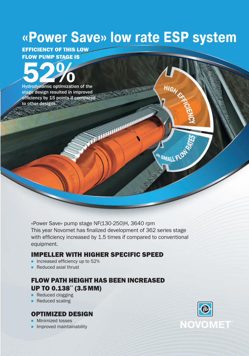
EFFICIENCY OF THIS LOW FLOW PUMP STAGE IS
52%Hydrodynamic optimization of the stage design resulted in improved effi ciency by 15 points if compared to other designs.
IMPELLER WITH HIGHER SPECIFIC SPEED ■ Increased effi ciency up to 52% ■ Reduced axial thrust
FLOW PATH HEIGHT HAS BEEN INCREASED UP TO 0.138'' (3.5 MM)
■ Reduced clogging ■ Reduced scaling
OPTIMIZED DESIGN ■ Minimized losses ■ Improved maintainability
«Power Save» pump stage NF(130-250)H, 3640 rpmThis year Novomet has fi nalized development of 362 series stage with effi ciency increased by 1.5 times if compared to conventional equipment.
«Power Save» low rate ESP system
3Novomet solutions ARSENAL #1(03) | January 2013
NOVOMET SOLUTIONS
ARSENALNovomet Solutions Arsenal
Novomet magazine # 1 (03),January 2013
Editor-in-Chief
Oleg Perelman
Commissioning Editor
Aleksey Maltsev
Design and prepress
Svetlana Starkova
Eduard Shidrikov
Authors:
Aleksandr Elizarov
Aleksandr Mokshaev
Aleksandr Rabinovich
Anatoly Santalov
Andrey Fedorov
Dmitriy Letunov
Evgenii Poshvin
Farkhat Khafizov
Ivan Khotsyanov
Maxim Perelman
Mansur Gabnasyrov
Mikhail Politov
Nadezhda Bezmaternykh
Oleg Perelman
Sergey Koshelev
Sergey Pescherenko
Samir Abakhri
Sharifzhan Ageev
Valeriy Minlikaev
Walid Reda
English version is prepared by International
Business Department:
Polina Plotnikova
Yana Batueva
Elena Grebennikova
Ekaterina Nalimova
Editorial office
Shosse Kosmonavtov, 395, Perm, 614065,
Russia
Tel: (342) 296 27 56, Fax: (342) 296 23 02
E-mail: [email protected]
www.novomet.ru
All rights reserved. No part of this
publication may be reproduced without the
prior written permission of the publisher.
JSC Novomet-Perm, 2013
CONTENTS
4 Innovations and Power Saving in Oil Production
6 Multi-Zone Production
8ESP Operation Experiencein the Conditions of Oil-gas Condensate Field with High Content of Sulphide Hydrogen
11 Slim-Line ESP systems
14 Influence of Viscosityon Operating Characteristics of Centrifugal Pumps
19Increase of motor temperature application range by means of motor cooling unit
22 Submersible Permanent Magnet Motors Background, design characteristics, capabilities
28 Permanent Magnet Motor application for ESP Artificial Lift
PLEASE KINDLY REFER TO PRODUCT SPECIFICATIONS
30 CONVENTIONAL PUMP SUMMARY (338 – 740 SERIES)
30 «POWER SAVE» PUMP SUMMARY (272 – 677 SERIES)
30 ASYNCHRONOUS MOTOR SUMMARY (378 - 744 SERIES)
31 PM MOTOR SUMMARY (319 - 512 SERIES)
31 GAS SEPARATOR, MULTIPHASE PUMP
31 PROTECTOR
32 SLOTTED SCREEN PUMP INTAKE
4Complete ESP systems/Water injection systems/Production optimization/Field service facilities/Software tools
INNOVATIONSAND POWER SAVINGIN OIL PRODUCTION
In modern oil machine building production of reliable equipment for various severe operating conditions is not enough. Today a winner is a company which pays proper attention to innovations, which equipment is ultimately the most power saving and allows to produce more oil and which local service centers ensure the best ESP operating conditions.
Novomet Group is one of such companies. Its activities are based on broad field experience and scientific investigations of employees.
sumed current to save electric power. These data were obtained from test well in strictly controlled conditions in Mos-cow R&D Center Konnas and indicated in presentations for representatives of Rus-sian and foreign oil operators.
In natural conditions commissioning of new ESP systems with maximum ef-ficiency ensured by proper sizing and selection allows to increase savings up to 30-40%. Active power was reduced by 21.7%, power intensity for 1 m3 of pro-duced fluid was reduced by 41.2%.
We have already supplied 800 ESP systems of this type. More than 300 ESP systems have already been started up.
Average measured reduction of power consumption is approximately 25%.
Slim-line ESP Systems
ESP system of 319 series is designed for operation in wells with casing of 4" (or wells after workover with primary casing of bigger diameter). Diameter of ESP system including cable is 3,74". Novomet has pioneered ESP industry with slim line ESP systems. Currently we are the only company in the whole world which manu-factures such ESP systems.
These ESP systems are also applicable in side-track wells due to small cross-
Recently the company has worked on increasing of design reliability. Reliable pumps designed for highly aggressive conditions like senoman or sulphide hy-drogen have been developed. Series range of pumps has been expanded regarding slim-line, high and low flow-rates. Also we can mention replacement of asynchronous motors by permanent magnet motors and increasing of heat and corrosion resistance. We have de-veloped new types of protectors, down-hole sensor systems and gas handling devices; also we started applying smart variable speed drives designed to ensure ESP operation at BEP.
Herewith, we would like to cover some recent developments.
«Power Save» ESP Systems
Novomet has been producing equip-ment allowing to save up to 20% of elec-tric power (it is called «power save») since 2010. Application of more efficient permanent magnet motor which efficien-cy is 92-94% (versus 84-86% of asyn-chronous motor), pump with new design stages which efficiency is by 5-6% higher than that of current design and also re-duction of heat losses in a cable, VSD and transformer due to decrease of con-
Oleg PerelmanGeneral Director
of ZAO Novomet-Perm
Mansur GabnasyrovDirector
of Novomet-Kazakhstan
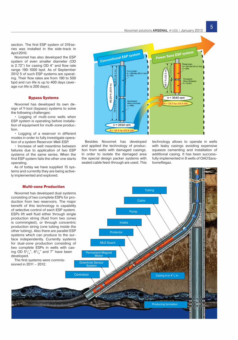
5Novomet solutions ARSENAL #1(03) | January 2013
Centralizer
Downhole Sensor System
Permanent Magnet Motor
MLE Guard
Protector
Intake
Pump
Cable
Tubing
technology allows to operate in wells with leaky casings avoiding expensive squeeze cementing and installation of additional casing. It has been success-fully implemented in 8 wells of OAO Sara-tovneftegaz.
Producing formation
Casing 4 or 41/
2 in
section. The first ESP system of 319 se-ries was installed in the side-track in April 2010.
Novomet has also developed the ESP system of even smaller diameter (OD is 2.72") for casing OD 4" and flow rate range 190-1000 bpd. As of September 2012 5 of such ESP systems are operat-ing. Their flow rates are from 190 to 500 bpd and run life is up to 400 days (aver-age run life is 200 days).
Bypass Systems
Novomet has developed its own de-sign of Y-tool (bypass) systems to solve the following challenges:
• Logging of multi-zone wells when ESP system is operating before installa-tion of equipment for multi-zone produc-tion.
• Logging of a reservoir in different modes in order to fully investigate opera-tion of a system Reservoir-Well-ESP.
• Increase of well meantime between failures due to application of two ESP systems of the same series. When the first ESP system fails the other one starts operating.
As of today we have supplied 15 sys-tems and currently they are being active-ly implemented and explored.
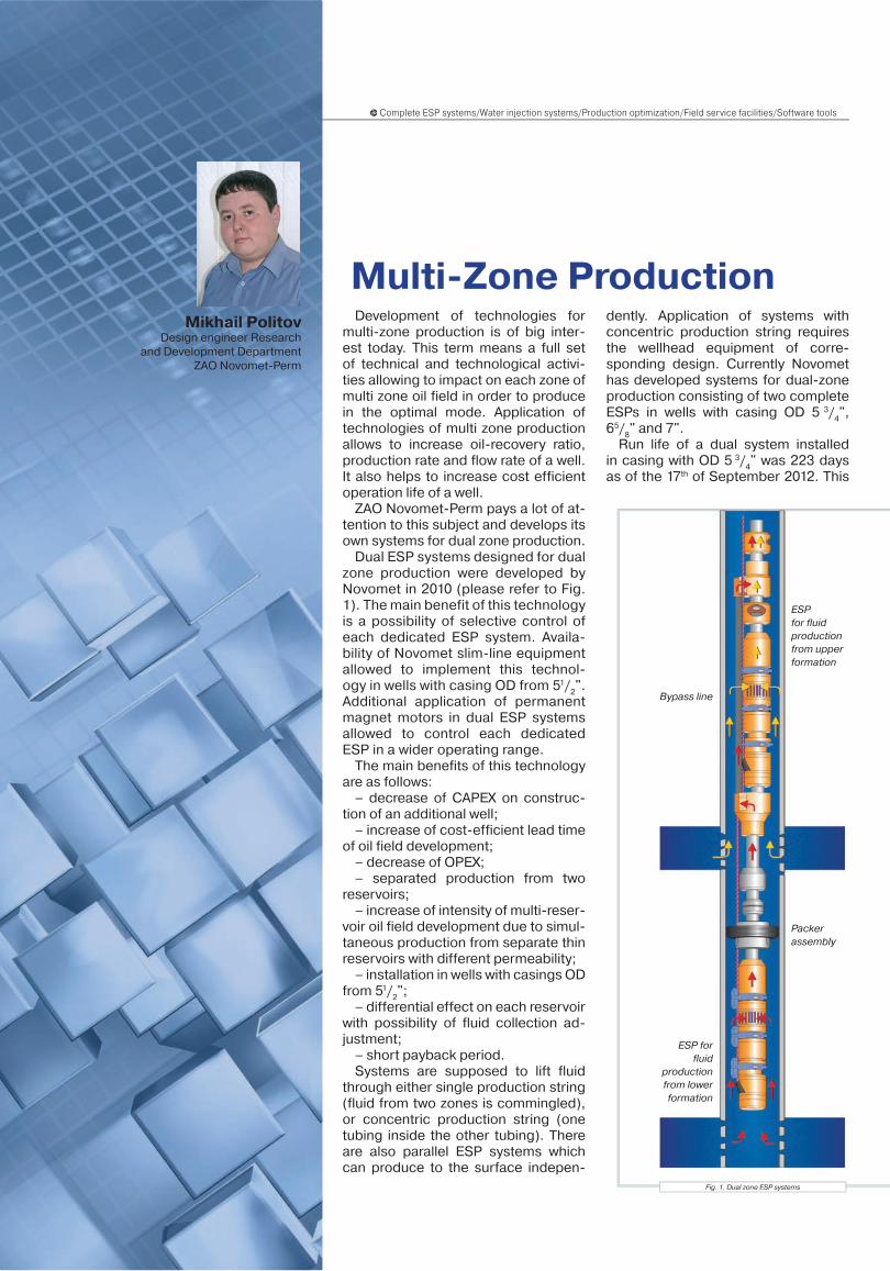
Multi-zone Production
Novomet has developed dual systems consisting of two complete ESPs for pro-duction from two reservoirs. The major benefit of this technology is capability of selective control of each ESP system. ESPs lift well fluid either through single production string (fluid from two zones is commingled), or through concentric production string (one tubing inside the other tubing). Also there are parallel ESP systems which can produce to the sur-face independently. Currently systems for dual-zone production consisting of two complete ESPs in wells with cas-ing OD 53/
4", 65/
8" and 7" have been
developed.The first systems were commis-
sioned in 2011 – 2012.
Besides Novomet has developed and applied the technology of produc-tion from wells with damaged casings. In order to isolate the damaged area the special design packer systems with sealed cable feed-through are used. This
6Complete ESP systems/Water injection systems/Production optimization/Field service facilities/Software tools
Multi-Zone ProductionDevelopment of technologies for
multi-zone production is of big inter-est today. This term means a full set of technical and technological activi-ties allowing to impact on each zone of multi zone oil field in order to produce in the optimal mode. Application of technologies of multi zone production allows to increase oil-recovery ratio, production rate and flow rate of a well. It also helps to increase cost efficient operation life of a well.
ZAO Novomet-Perm pays a lot of at-tention to this subject and develops its own systems for dual zone production.
Dual ESP systems designed for dual zone production were developed by Novomet in 2010 (please refer to Fig. 1). The main benefit of this technology is a possibility of selective control of each dedicated ESP system. Availa-bility of Novomet slim-line equipment allowed to implement this technol-ogy in wells with casing OD from 51/
2".
Additional application of permanent magnet motors in dual ESP systems allowed to control each dedicated ESP in a wider operating range.
The main benefits of this technology are as follows:
– decrease of CAPEX on construc-tion of an additional well;
– increase of cost-efficient lead time of oil field development;
– decrease of OPEX;– separated production from two
reservoirs;– increase of intensity of multi-reser-
voir oil field development due to simul-taneous production from separate thin reservoirs with different permeability;
– installation in wells with casings OD from 51/
2";
– differential effect on each reservoir with possibility of fluid collection ad-justment;
– short payback period.Systems are supposed to lift fluid
through either single production string (fluid from two zones is commingled), or concentric production string (one tubing inside the other tubing). There are also parallel ESP systems which can produce to the surface indepen-
Fig. 1. Dual zone ESP systems
dently. Application of systems with concentric production string requires the wellhead equipment of corre-sponding design. Currently Novomet has developed systems for dual-zone production consisting of two complete ESPs in wells with casing OD 5 3/
4",
65/8" and 7".
Run life of a dual system installed in casing with OD 5 3/
4" was 223 days
as of the 17th of September 2012. This
Mikhail PolitovDesign engineer Research
and Development DepartmentZAO Novomet-Perm
ESP for fluid production from upper formation
Packerassembly
Bypass line
ESP for fluid
production from lower formation
7Novomet solutions ARSENAL #1(03) | January 2013
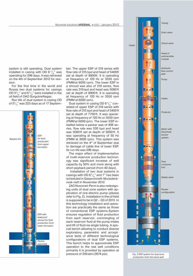
Fig. 2 ESP system for dual zone production from the same well
system is still operating. Dual system installed in casing with OD 6 5/
8" was
operating for 296 days. It was retrieved on the 4th of September 2012 for revi-sion.
For the first time in the world and Russia two dual systems for casings OD 53/
4" and 6 5/
8" were installed in the
oil field of OAO Surgutneftegas.Run life of dual system in casing OD
of 53/4" was 223 days as of 17 Septem-
ber. The upper ESP of 319 series with flow rate of 315 bpd and head of 5400ft set at depth of 8800ft. It is operating at frequency of 120 Hz or 3550 rpm (PMM at 6000 rpm). The lower ESP in a shroud was also of 319 series, flow rate was 315 bpd and head was 5080 ft set at depth of 8900 ft. It is operating at frequency of 120 Hz or 3550 rpm (PMM at 6000 rpm).
Dual system in casing OD 6 5/8" con-
sisted of upper ESP of 319 series with flow rate of 315 bpd and head of 5400 ft set at depth of 7700 ft. It was operat-ing at frequency of 120 Hz or 3550 rpm (PMM at 6000 rpm). The lower ESP in-stalled below a packer was of 406 se-ries, flow rate was 530 bpd and head was 5080 ft set at depth of 9200 ft. It was operating at frequency of 50 Hz (PMM at 3000 rpm). This system was retrieved on the 4th of September due to damage of cable line of lower ESP. Its run life was 296 days.
The major effect of implementation of multi-reservoir production technol-ogy was significant increase of well capacity by 50% and more along with short payback period (from 40 days).
Installation of two dual systems in casings with OD 6 5/
8" and 7" has been
scheduled in Gaspromneft-Muravlenk-ovsk-neft in November 2012.
ZAO Novomet-Perm is also redesign-ing units of dual zone system with ap-plication of one electric pump (please refer to Fig. 2). Installation in the oil field is supposed to be in Q2 – Q3 of 2013. In this technology installation and opera-tion are practically the same as those of conventional ESP systems.System ensures regulation of fluid production from each reservoir, commingling of each reservoir fluid at the pump intake and lift of fluid via single tubing. A spe-cial bench allowing to conduct diverse exploratory, parametric and accept-ance tests of different technological configurations of dual ESP systems. This bench helps to approximate ESP operation to the real well conditions primarily it is provided by operation at pressure of 250 atm (3674 psi).
ESP withleakproof shroud for fluid production from lower formation
ESP for fluid production from upper formation
Tubing
Drain valve
Check valveCable
Head of submersible module
Hydraulic flow control pipe
Pump
Intake
Protector
Motor with Downhole sensor system
Flow crossover tool
Packer configuration
Safety valve
Packer assembly
Bypass line
8Complete ESP systems/Water injection systems/Production optimization/Field service facilities/Software tools
ESP Operation Experiencein the Conditions of Oil-gas Condensate Field
with High Content of Sulphide Hydrogen
In this article we are considering experience of installation of artificial lift equipment in Orenburg oil-gas condensate field of OOO Gazprom Dobycha Orenburg. Operating conditions of this oil field are characterized by high content of Sulphide Hydrogen in the produced fluid. It leads to sulphide stress cracking of equipment. We have developed highly reliable ESP systems of ultra corrosion resistant design combining efforts of oil operator and manufacturer of oil producing equipment.
In 1966 the unique oil-gas condensate field was discovered 30 km from Oren-burg on the border between Europe and Asia. It had uncommon reserves and gas content. The special Office for De-velopment and Operation of Gas Field and Construction of Gas Pipelines was established in 1968. This company was called OOO Gazprom Dobycha Oren-burg in 2008. Gas production was start-ed in 1974. Gas processing and helium plants were constructed for recovery of products containing hydrocarbon com-ponents, hydrogen sulphide, sour sulfur and helium. The major challenge was high content of hydrogen sulphide in produced gas (up to 6%).
Oil production has been also the ur-gent problem for the company since the middle of 2000s. Nowadays oil wells are produced by gas-lift only. However amount of gas was limited and special-ists of OOO Gazprom Dobycha Orenburg sized and selected equipment for artifi-cial lift production.
In accordance with project solutions on development of Orenburg oil-gas condensate field the Central Committee planned to install artificial lift pumping equipment.
Initial attempts of implementation of ar-tificial lift equipment in this oil field were made in 2006-2007. At this stage jet and progressive cavity pumps were selected for tests. At that time sucker rod pumps and ESP systems needed improvement for operation in the conditions of high sul-phide hydrogen and were not considered.
Trial operation of jet and progressive cavity pumps showed that these types of artificial lift production could be recom-mended for a wide or selective imple-mentation.
But given the recent work on improve-ment of pumping systems for oil produc-tion specialists of OOO Gazprom Doby-cha Orenburg decided to conduct trial operation of ESP systems.
They analyzed the information about ESP manufacturers and also conducted preliminary negotiations with them. Fi-nally OOO Gazprom Dobycha Orenburg selected ESP systems produced by ZAO Novomet-Perm (hereinafter referred to as – Novomet).
This decision was caused by:• Novomet successful operating expe-
rience in the oil fields characterized by high gas-to-oil ratio and presence of aggressive components in the res-ervoir fluid;
Valeriy MinlikaevHead of Gas and Gas Condensate (Oil)
Production Office OAO Gazprom
Aleksandr MokshaevSenior Engineer
OOO Gazprom dobycha Orenburg
Farkhat KhafizovGeneral Director
OOO Novomet-Service
Aleksandr ElizarovDirector of branch Novomet-South
Aleksandr RabinovichAdvisor of General Director
ZAO Novomet-Perm on innovative equipment
Nadezhda BezmaternykhHead of Materials Science Lab
ZAO Novomet-Perm
9Novomet solutions ARSENAL #1(03) | January 2013
• beneficial conditions of provision of equipment during the trial operation (provision of equipment on leasing conditions);
• full service maintenance of supplied equipment by Novomet-Service. It includes sizing and selection of the equipment, delivery, installation/dis-mantling, start-up, commissioning, supervising (permanent technical control and maintenance during the contract validity period) and RIH and POOH operations if required;
• convenient location of service center Novomet-South (Sorochinsk, Oren-burg region close to this oil field).
Trial operation was conducted in the oil well # 558n of the Fallow Asselskaya oil field.
Sizing and selection of the equipment was based on provided initial reservoir and well data and properties of reser-voir fluids. This well was produced by gas-lift before. Capacity of this well was 12 m3/ day (75 bpd). After replacement according to the calculations it was sup-posed to produce 21 m3/day (130 bpd).
In terms of the data provided by tech-nological service of OOO Gazprom Do-bycha Orenburg the vortex ESP system with capacity of 25 m3/day (157 bpd) and head of 850 m (2788 f) was offered for the optimal operating mode. Consider-ing high content of sulphide hydrogen all ESP system components (pump, mo-tor, protector, gas separator, check and drain valves, downhole sensor system, cable line) were not only of corrosion re-sistant design but were produced from materials in accordance with require-ments of standard NACE MRO 175-01 and tested in highly sulphide environ-ment in the laboratory Nadezhnost of
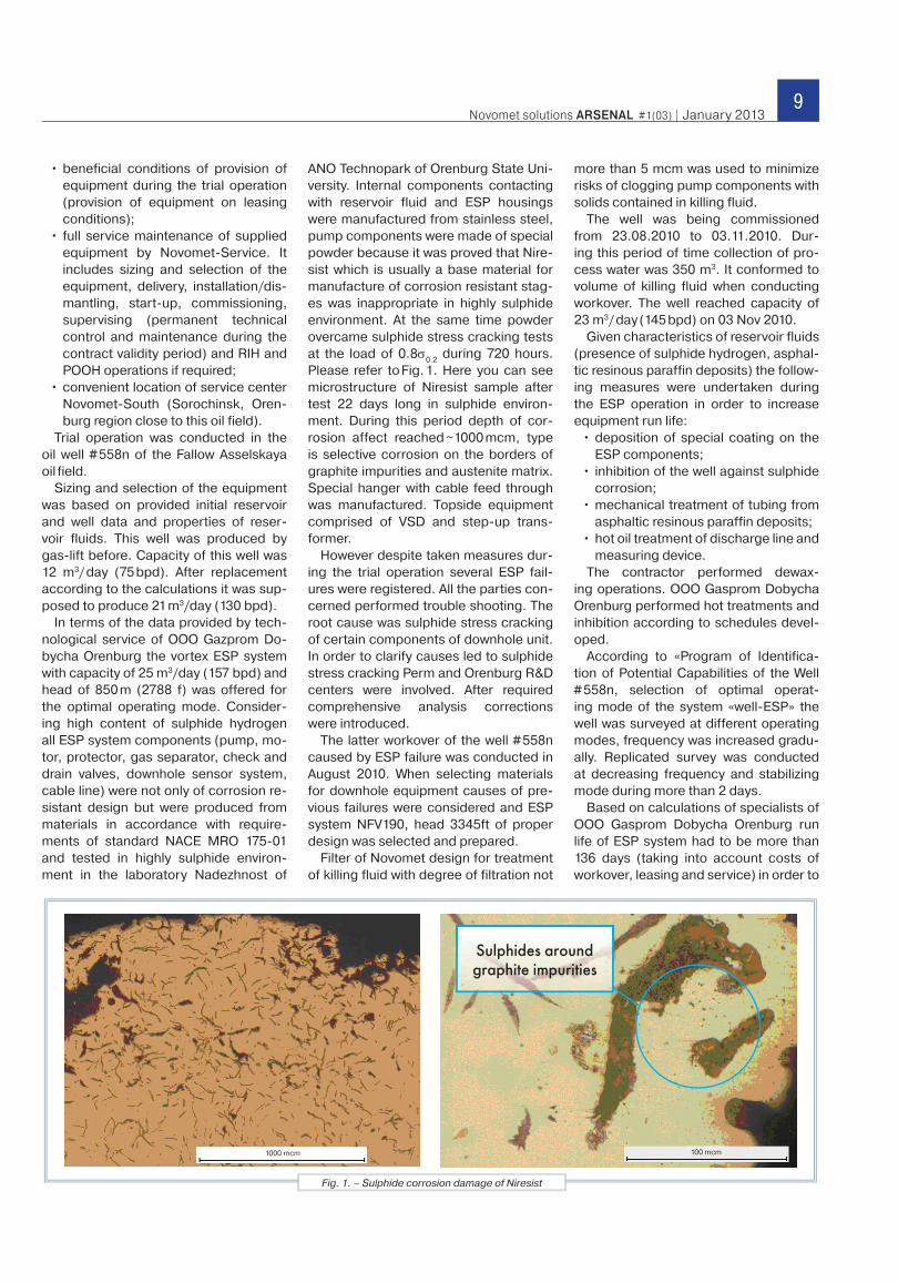
ANO Technopark of Orenburg State Uni-versity. Internal components contacting with reservoir fluid and ESP housings were manufactured from stainless steel, pump components were made of special powder because it was proved that Nire-sist which is usually a base material for manufacture of corrosion resistant stag-es was inappropriate in highly sulphide environment. At the same time powder overcame sulphide stress cracking tests at the load of 0.8σ0.2
during 720 hours. Please refer to Fig. 1. Here you can see microstructure of Niresist sample after test 22 days long in sulphide environ-ment. During this period depth of cor-rosion affect reached ~1000 mcm, type is selective corrosion on the borders of graphite impurities and austenite matrix. Special hanger with cable feed through was manufactured. Topside equipment comprised of VSD and step-up trans-former.
However despite taken measures dur-ing the trial operation several ESP fail-ures were registered. All the parties con-cerned performed trouble shooting. The root cause was sulphide stress cracking of certain components of downhole unit. In order to clarify causes led to sulphide stress cracking Perm and Orenburg R&D centers were involved. After required comprehensive analysis corrections were introduced.
The latter workover of the well # 558n caused by ESP failure was conducted in August 2010. When selecting materials for downhole equipment causes of pre-vious failures were considered and ESP system NFV190, head 3345ft of proper design was selected and prepared.
Filter of Novomet design for treatment of killing fluid with degree of filtration not
more than 5 mcm was used to minimize risks of clogging pump components with solids contained in killing fluid.
The well was being commissioned from 23.08.2010 to 03.11.2010. Dur-ing this period of time collection of pro-cess water was 350 m3. It conformed to volume of killing fluid when conducting workover. The well reached capacity of 23 m3/ day (145 bpd) on 03 Nov 2010.
Given characteristics of reservoir fluids (presence of sulphide hydrogen, asphal-tic resinous paraffin deposits) the follow-ing measures were undertaken during the ESP operation in order to increase equipment run life:
• deposition of special coating on the ESP components;
• inhibition of the well against sulphide corrosion;
• mechanical treatment of tubing from asphaltic resinous paraffin deposits;
• hot oil treatment of discharge line and measuring device.
The contractor performed dewax-ing operations. OOO Gasprom Dobycha Orenburg performed hot treatments and inhibition according to schedules devel-oped.
According to «Program of Identifica-tion of Potential Capabilities of the Well # 558n, selection of optimal operat-ing mode of the system «well-ESP» the well was surveyed at different operating modes, frequency was increased gradu-ally. Replicated survey was conducted at decreasing frequency and stabilizing mode during more than 2 days.
Based on calculations of specialists of OOO Gasprom Dobycha Orenburg run life of ESP system had to be more than 136 days (taking into account costs of workover, leasing and service) in order to
Fig. 1. – Sulphide corrosion damage of Niresist
Sulphides around graphite impurities
1000 mcm 100 mcm
10Complete ESP systems/Water injection systems/Production optimization/Field service facilities/Software tools
1 Sept 2011. Total run life was 377 days. Visual corrosion traces were not discov-ered. Then the ESP system was delivered to the manufacturer for revision and lab-oratory analysis.
Presence of asphaltic resinous paraf-fin deposits in pump and gas separator internal cavities were revealed. Also spe-cialists found insignificant traces of wear of pump operating components. Motor and protector were not damaged.
The following results were obtained during laboratory tests of ESP compo-nents:
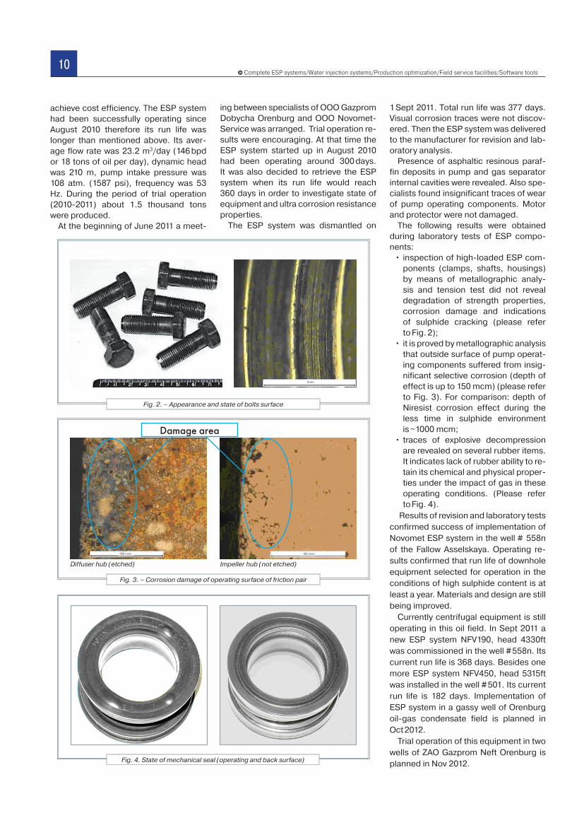
• inspection of high-loaded ESP com-ponents (clamps, shafts, housings) by means of metallographic analy-sis and tension test did not reveal degradation of strength properties, corrosion damage and indications of sulphide cracking (please refer to Fig. 2);
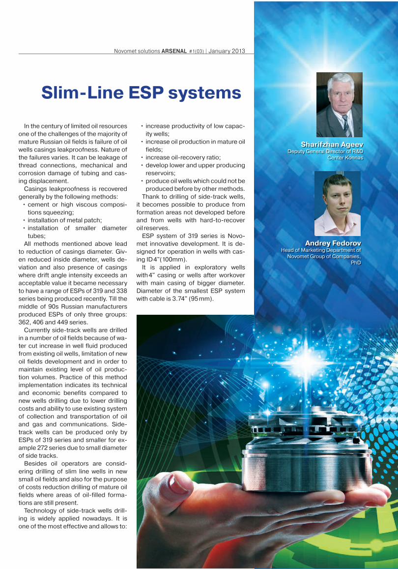
• it is proved by metallographic analysis that outside surface of pump operat-ing components suffered from insig-nificant selective corrosion (depth of effect is up to 150 mcm) (please refer to Fig. 3). For comparison: depth of Niresist corrosion effect during the less time in sulphide environment is ~1000 mcm;
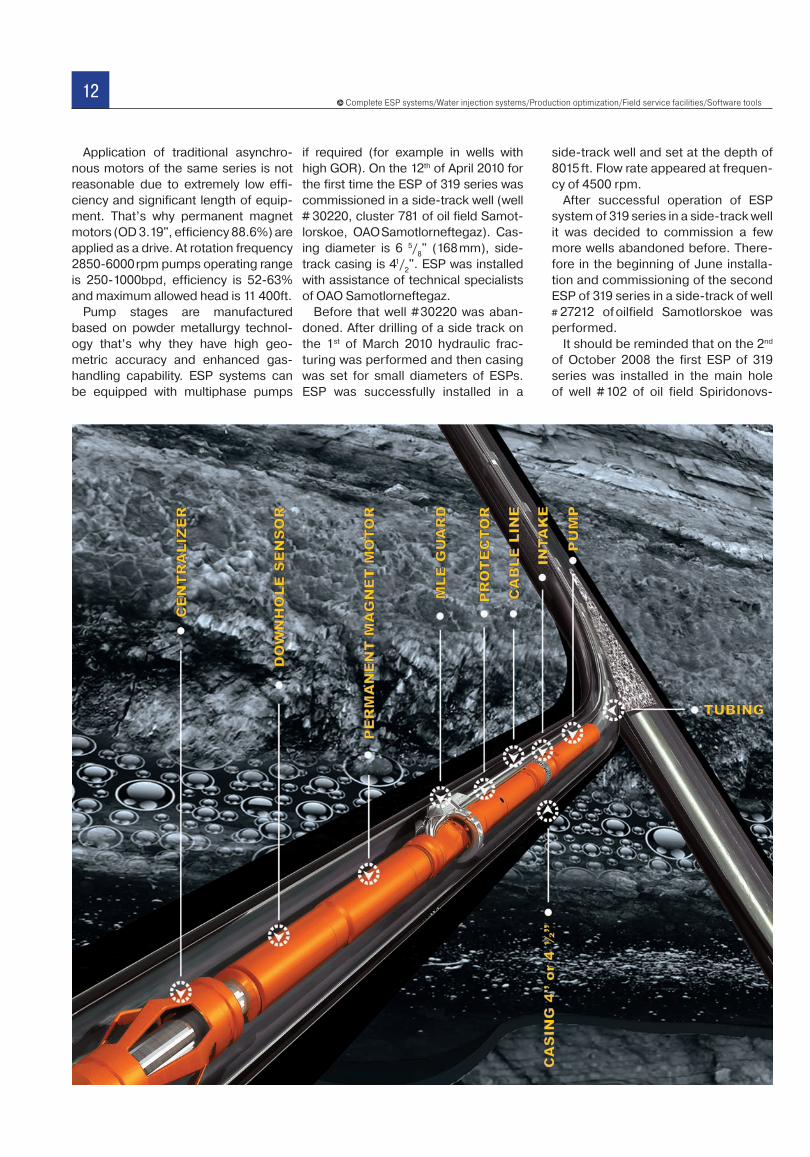
• traces of explosive decompression are revealed on several rubber items. It indicates lack of rubber ability to re-tain its chemical and physical proper-ties under the impact of gas in these operating conditions. (Please refer to Fig. 4).
Results of revision and laboratory tests confirmed success of implementation of Novomet ESP system in the well # 558n of the Fallow Asselskaya. Operating re-sults confirmed that run life of downhole equipment selected for operation in the conditions of high sulphide content is at least a year. Materials and design are still being improved.
Currently centrifugal equipment is still operating in this oil field. In Sept 2011 a new ESP system NFV190, head 4330ft was commissioned in the well # 558n. Its current run life is 368 days. Besides one more ESP system NFV450, head 5315ft was installed in the well # 501. Its current run life is 182 days. Implementation of ESP system in a gassy well of Orenburg oil-gas condensate field is planned in Oct 2012.
Trial operation of this equipment in two wells of ZAO Gazprom Neft Orenburg is planned in Nov 2012.
achieve cost efficiency. The ESP system had been successfully operating since August 2010 therefore its run life was longer than mentioned above. Its aver-age flow rate was 23.2 m3/day (146 bpd or 18 tons of oil per day), dynamic head was 210 m, pump intake pressure was 108 atm. (1587 psi), frequency was 53 Hz. During the period of trial operation (2010-2011) about 1.5 thousand tons were produced.
At the beginning of June 2011 a meet-
ing between specialists of OOO Gazprom Dobycha Orenburg and OOO Novomet-Service was arranged. Trial operation re-sults were encouraging. At that time the ESP system started up in August 2010 had been operating around 300 days. It was also decided to retrieve the ESP system when its run life would reach 360 days in order to investigate state of equipment and ultra corrosion resistance properties.
The ESP system was dismantled on
Fig. 3. – Corrosion damage of operating surface of friction pair
Fig. 4. State of mechanical seal (operating and back surface)
Fig. 2. – Appearance and state of bolts surface
Damage area
Diffuser hub (etched) Impeller hub (not etched)
2 mm
100 mcm300 mcm
11Novomet solutions ARSENAL #1(03) | January 2013
Slim-Line ESP systems
In the century of limited oil resources one of the challenges of the majority of mature Russian oil fields is failure of oil wells casings leakproofness. Nature of the failures varies. It can be leakage of thread connections, mechanical and corrosion damage of tubing and cas-ing displacement.
Casings leakproofness is recovered generally by the following methods:
• cement or high viscous composi-tions squeezing;
• installation of metal patch;• installation of smaller diameter
tubes;All methods mentioned above lead
to reduction of casings diameter. Giv-en reduced inside diameter, wells de-viation and also presence of casings where drift angle intensity exceeds an acceptable value it became necessary to have a range of ESPs of 319 and 338 series being produced recently. Till the middle of 90s Russian manufacturers produced ESPs of only three groups: 362, 406 and 449 series.
Currently side-track wells are drilled in a number of oil fields because of wa-ter cut increase in well fluid produced from existing oil wells, limitation of new oil fields development and in order to maintain existing level of oil produc-tion volumes. Practice of this method implementation indicates its technical and economic benefits compared to new wells drilling due to lower drilling costs and ability to use existing system of collection and transportation of oil and gas and communications. Side-track wells can be produced only by ESPs of 319 series and smaller for ex-ample 272 series due to small diameter of side tracks.
Besides oil operators are consid-ering drilling of slim line wells in new small oil fields and also for the purpose of costs reduction drilling of mature oil fields where areas of oil-filled forma-tions are still present.
Technology of side-track wells drill-ing is widely applied nowadays. It is one of the most effective and allows to:
• increase productivity of low capac-ity wells;
• increase oil production in mature oil fields;
• increase oil-recovery ratio;• develop lower and upper producing
reservoirs;• produce oil wells which could not be
produced before by other methods. Thank to drilling of side-track wells,
it becomes possible to produce from formation areas not developed before and from wells with hard-to-recover oil reserves.
ESP system of 319 series is Novo-met innovative development. It is de-signed for operation in wells with cas-ing ID 4"(100mm).
It is applied in exploratory wells with 4" casing or wells after workover with main casing of bigger diameter. Diameter of the smallest ESP system with cable is 3.74" (95 mm).
Sharifzhan AgeevDeputy General Director of R&D
Center Konnas
Andrey FedorovHead of Marketing Department of
Novomet Group of Companies,PhD
12Complete ESP systems/Water injection systems/Production optimization/Field service facilities/Software tools
Application of traditional asynchro-nous motors of the same series is not reasonable due to extremely low effi-ciency and significant length of equip-ment. That’s why permanent magnet motors (OD 3.19", efficiency 88.6%) are applied as a drive. At rotation frequency 2850-6000 rpm pumps operating range is 250-1000bpd, efficiency is 52-63% and maximum allowed head is 11 400ft.
Pump stages are manufactured based on powder metallurgy technol-ogy that’s why they have high geo-metric accuracy and enhanced gas-handling capability. ESP systems can be equipped with multiphase pumps
if required (for example in wells with high GOR). On the 12th of April 2010 for the first time the ESP of 319 series was commissioned in a side-track well (well # 30220, cluster 781 of oil field Samot-lorskoe, OAO Samotlorneftegaz). Cas-ing diameter is 6 5/
8" (168 mm), side-
track casing is 41/2". ESP was installed
with assistance of technical specialists of OAO Samotlorneftegaz.
Before that well # 30220 was aban-doned. After drilling of a side track on the 1st of March 2010 hydraulic frac-turing was performed and then casing was set for small diameters of ESPs. ESP was successfully installed in a
side-track well and set at the depth of 8015 ft. Flow rate appeared at frequen-cy of 4500 rpm.
After successful operation of ESP system of 319 series in a side-track well it was decided to commission a few more wells abandoned before. There-fore in the beginning of June installa-tion and commissioning of the second ESP of 319 series in a side-track of well # 27212 of oilfield Samotlorskoe was performed.
It should be reminded that on the 2nd
of October 2008 the first ESP of 319 series was installed in the main hole of well # 102 of oil field Spiridonovs-
13Novomet solutions ARSENAL #1(03) | January 2013
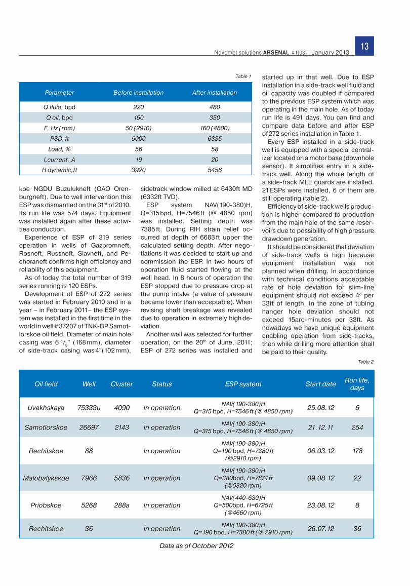
Parameter Before installation After installation
Q fluid, bpd 220 480
Q oil, bpd 160 350
F, Hz (rpm) 50 (2910) 160 (4800)
PSD, ft 5000 6335
Load, % 56 58
I,current.,А 19 20
H dynamic,ft 3920 5456
koe NGDU Buzulukneft (OAO Oren-burgneft). Due to well intervention this ESP was dismantled on the 31st of 2010. Its run life was 574 days. Equipment was installed again after these activi-ties conduction.
Experience of ESP of 319 series operation in wells of Gazpromneft, Rosneft, Russneft, Slavneft, and Pe-choraneft confirms high efficiency and reliability of this equipment.
As of today the total number of 319 series running is 120 ESPs.
Development of ESP of 272 series was started in February 2010 and in a year – in February 2011– the ESP sys-tem was installed in the first time in the world in well # 37207 of TNK-BP Samot-lorskoe oil field. Diameter of main hole casing was 6 5/
8" (168 mm), diameter
of side-track casing was 4"(102 mm),
sidetrack window milled at 6430ft MD (6332ft TVD).
ESP system NAV(190-380)H, Q=315 bpd, H=7546 ft (@ 4850 rpm) was installed. Setting depth was 7385 ft. During RIH strain relief oc-curred at depth of 6683 ft upper the calculated setting depth. After nego-tiations it was decided to start up and commission the ESP. In two hours of operation fluid started flowing at the well head. In 8 hours of operation the ESP stopped due to pressure drop at the pump intake (a value of pressure became lower than acceptable). When revising shaft breakage was revealed due to operation in extremely high de-viation.
Another well was selected for further operation, on the 20th of June, 2011; ESP of 272 series was installed and
started up in that well. Due to ESP installation in a side-track well fluid and oil capacity was doubled if compared to the previous ESP system which was operating in the main hole. As of today run life is 491 days. You can find and compare data before and after ESP of 272 series installation in Table 1.
Every ESP installed in a side-track well is equipped with a special central-izer located on a motor base (downhole sensor). It simplifies entry in a side-track well. Along the whole length of a side-track MLE guards are installed. 21 ESPs were installed, 6 of them are still operating (table 2).
Efficiency of side-track wells produc-tion is higher compared to production from the main hole of the same reser-voirs due to possibility of high pressure drawdown generation.
It should be considered that deviation of side-track wells is high because equipment installation was not planned when drilling. In accordance with technical conditions acceptable rate of hole deviation for slim-line equipment should not exceed 4o per 33ft of length. In the zone of tubing hanger hole deviation should not exceed 15arc-minutes per 33ft. As nowadays we have unique equipment enabling operation from side-tracks, then while drilling more attention shall be paid to their quality.
Oil field Well Cluster Status ESP system Start date Run life, days
Uvakhskaya 75333u 4090 In operationNAV(190-380)H
Q=315 bpd, H=7546 ft (@ 4850 rpm)25.08.12 6
Samotlorskoe 26697 2143 In operationNAV(190-380)H
Q=315 bpd, H=7546 ft (@ 4850 rpm)21.12.11 254
Rechitskoe 88 In operationNAV(190-380)H
Q=190 bpd, H=7380 ft(@2910 rpm)
06.03.12 178
Malobalykskoe 7966 583б In operationNAV(190-380)H
Q=380bpd, H=7874 ft(@5820 rpm)
09.08.12 22
Priobskoe 5268 288а In operationNAV(440-630)H
Q=500bpd, H=6725 ft(@4660 rpm)
23.08.12 8
Rechitskoe 36 In operationNAV(190-380)H
Q=190 bpd, H=7380 ft (@ 2910 rpm)26.07.12 36
Table 1
Table 2
Data as of October 2012
14Complete ESP systems/Water injection systems/Production optimization/Field service facilities/Software tools
Influence of Viscosityon Operating Characteristics of Centrifugal Pumps
Usually operating characteristics of submersible pumps in highly viscous fluid are calculated on the base of operating characteristics in water using empirical dependences established more than 50 years ago. Error of this calculation is 10-25% and it is due to the change of pump construction within this period of time. We conducted direct measurements of operating characteristics of serial pump stages of 319, 338, 362 and 406 series with rated flow rate of up to 1890 bpd in viscosity range 10 – 400 cSt. Error of measurement of head, flow rate and power was 5%. We suggested a method of pump selection and sizing for highly viscous oil wells.
Influence of fluid viscosity on operat-ing characteristics of centrifugal pump was the issue of high interest for many decades. Every year reserves of easily producing lowly viscous oil reduce and production of highly viscous oil becomes more and more actual. Very often it can be produced by centrifugal pumps how-ever we should consider viscosity influ-ence on operating characteristics when selecting and sizing.
Currently two groups of models are ap-plied for forecasting of operating char-acteristics of pumps producing viscous fluids. They are empiric and calculating.
Empiric methods allow to obtain char-acteristics of pump producing viscous fluid on the base of recalculation of char-acteristics in water by unitless param-eters and equalizing factors obtained from experiments in highly viscous fluid. Often such methods give acceptable re-sults only when a pump operates at best efficiency point. It is sufficient constraint if a centrifugal pump is applied for lift of fluid from an oil well. It is caused by the fact that equalizing factors were calcu-lated only for model pumps and not for pumps applied nowadays. Benefit of this method is that it allows to determine characteristics if testing data in water are available.
One of empiric methods was sug-gested by Mr. Stepanov [1] for submers-ible pumps. The other method was sug-gested by the USA hydraulic Institute [2], where pumps of various OD were tested in a wide range of flow rates and heads in fluid of various viscosity from 1 cSt to 3600 cSt.
Procedure of Mr. Gulich [3] is based on assessment of viscous losses inside a pump.
According to data of Mr. Gulich and Mr. Lee [4] Hydraulic Institute carried out tests within narrow limits of pump specific speed which were not common to oil pumps. Mr. Lee collected data on operation of conventional pump API in water and oil with viscosity form 1 to 200 cSt. Its equalizing factors differed from factors of Hydraulic Institute by 10% re-garding head, 5% regarding flow rate and 9.7% regarding efficiency.
In the report [5], presented on the an-nual SPE Workshop, USA, 2007 it was in-dicated that such methods of calculation of equalizing factors might be incorrect in case of pumps different from models.
Soviet scientist Mr. Lyapkov [6] sug-gested his own method based on ex-perimental data of tests of submersible pumps in viscous fluid. It showed factors for recalculation of head and efficiency
1. L. Stepanov Centrifugal and Axial Pumps – theory, design and application, the second edition, State Scientific and Technical Publishing House of Machine Building Literature, 1960.2. Hydraulic Institute, Standard for Effects of Liquid Viscosity on Rotodynamic (Centrifugal and Vertical) Pump Performance, 1983, USA.3. Gulich J.F., Centrifugal pumps. Second Edition, Springer, 2010.4. Li V.G. Experimental Research of Technical Characteristic centrifugal pumps. World Pumps, 2002, №26.5. Gilmar Amaral, Valdir Estevam, Petroleo Brasileiro and Fernando A. Franco, SPE, State University of Campinas, Influence of Viscosity on ESP Performance, 2007 SPE Annual Technical Conference and Exhibition, Anaheim, California, 11 – 14 November.
Samir AbakhriResearch engineer of Engineering
Technical Center of R&D Department,ZAO Novomet-Perm
Maxim PerelmanVP International
ZAO Novomet-Perm
Aleksandr RabinovichAdvisor of General Director
on New EquipmentZAO Novomet-Perm
Sergey PescherenkoHead of Engineering Technical Center
of R&D Department, ZAO Novomet-Perm
PhD
15Novomet solutions ARSENAL #1(03) | January 2013
for different flow rates depending on fluid viscosity. Many Russian companies use recalculation methods based on method of Mr. Lyapkov.
Computation models use computa-tional fluid dynamics, CFD for calculation of flow in pump flow channels and esti-mation of viscosity influence on the final characteristics. Their main disadvan-tages are as follows: high work content, sufficient duration, usage of turbulence empirical models tested for conditions different from researched and that’s why very often results do not ensure correct forecast of characteristics.
It is obvious that empirical model is preferable because its accuracy and ap-plicability is higher than those of compu-tation model. As it is shown above results of empirical meth-ods depend on pump construction and testing conditions and they can differ from each other significantly. Construction of oil pumps is constantly being enhanced. New technologies of stages manufacturing, for example, powder technology [7], or new centrifugal vortex and Power Save pump stages [8] ap-pear. That is why it is not correct to apply generic methods de-veloped many years ago to contemporary centrifugal pumps. It is necessary to determine dependence of operating charac-teristics change on fluid viscosity experimentally for accurate recalculation of submersible pump characteristics. Develop-ment of computerized benches with accurate electronic sen-sors allows to read out actual parameters of stages quicker and more accurate that by CFD calculation.
Experimental ESP system and Tests
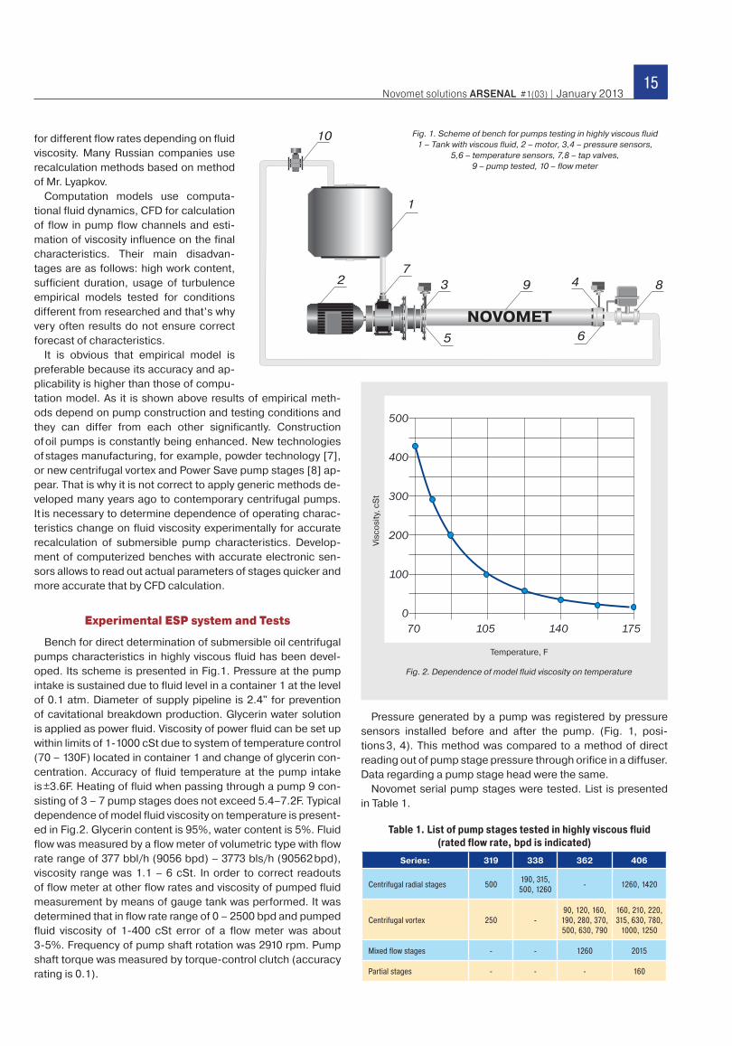
Bench for direct determination of submersible oil centrifugal pumps characteristics in highly viscous fluid has been devel-oped. Its scheme is presented in Fig.1. Pressure at the pump intake is sustained due to fluid level in a container 1 at the level of 0.1 atm. Diameter of supply pipeline is 2.4" for prevention of cavitational breakdown production. Glycerin water solution is applied as power fluid. Viscosity of power fluid can be set up within limits of 1-1000 cSt due to system of temperature control (70 – 130F) located in container 1 and change of glycerin con-centration. Accuracy of fluid temperature at the pump intake is ±3.6F. Heating of fluid when passing through a pump 9 con-sisting of 3 – 7 pump stages does not exceed 5.4–7.2F. Typical dependence of model fluid viscosity on temperature is present-ed in Fig.2. Glycerin content is 95%, water content is 5%. Fluid flow was measured by a flow meter of volumetric type with flow rate range of 377 bbl/h (9056 bpd) – 3773 bls/h (90562 bpd), viscosity range was 1.1 – 6 cSt. In order to correct readouts of flow meter at other flow rates and viscosity of pumped fluid measurement by means of gauge tank was performed. It was determined that in flow rate range of 0 – 2500 bpd and pumped fluid viscosity of 1-400 cSt error of a flow meter was about 3-5%. Frequency of pump shaft rotation was 2910 rpm. Pump shaft torque was measured by torque-control clutch (accuracy rating is 0.1).
Pressure generated by a pump was registered by pressure sensors installed before and after the pump. (Fig. 1, posi-tions 3, 4). This method was compared to a method of direct reading out of pump stage pressure through orifice in a diffuser. Data regarding a pump stage head were the same.
Novomet serial pump stages were tested. List is presented in Table 1.
Table 1. List of pump stages tested in highly viscous fluid (rated flow rate, bpd is indicated)
Series: 319 338 362 406
Centrifugal radial stages 500190, 315, 500, 1260
- 1260, 1420
Centrifugal vortex 250 -90, 120, 160,
190, 280, 370, 500, 630, 790
160, 210, 220, 315, 630, 780,
1000, 1250
Mixed flow stages - - 1260 2015
Partial stages - - - 160
Fig. 1. Scheme of bench for pumps testing in highly viscous fluid 1 – Tank with viscous fluid, 2 – motor, 3,4 – pressure sensors,
5,6 – temperature sensors, 7,8 – tap valves, 9 – pump tested, 10 – flow meter
Fig. 2. Dependence of model fluid viscosity on temperature
Vis
cosi
ty, c
St
Temperature, F
16Complete ESP systems/Water injection systems/Production optimization/Field service facilities/Software tools
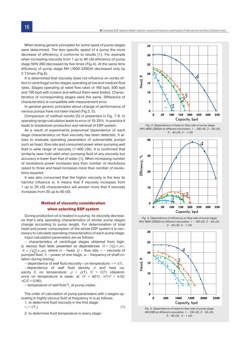
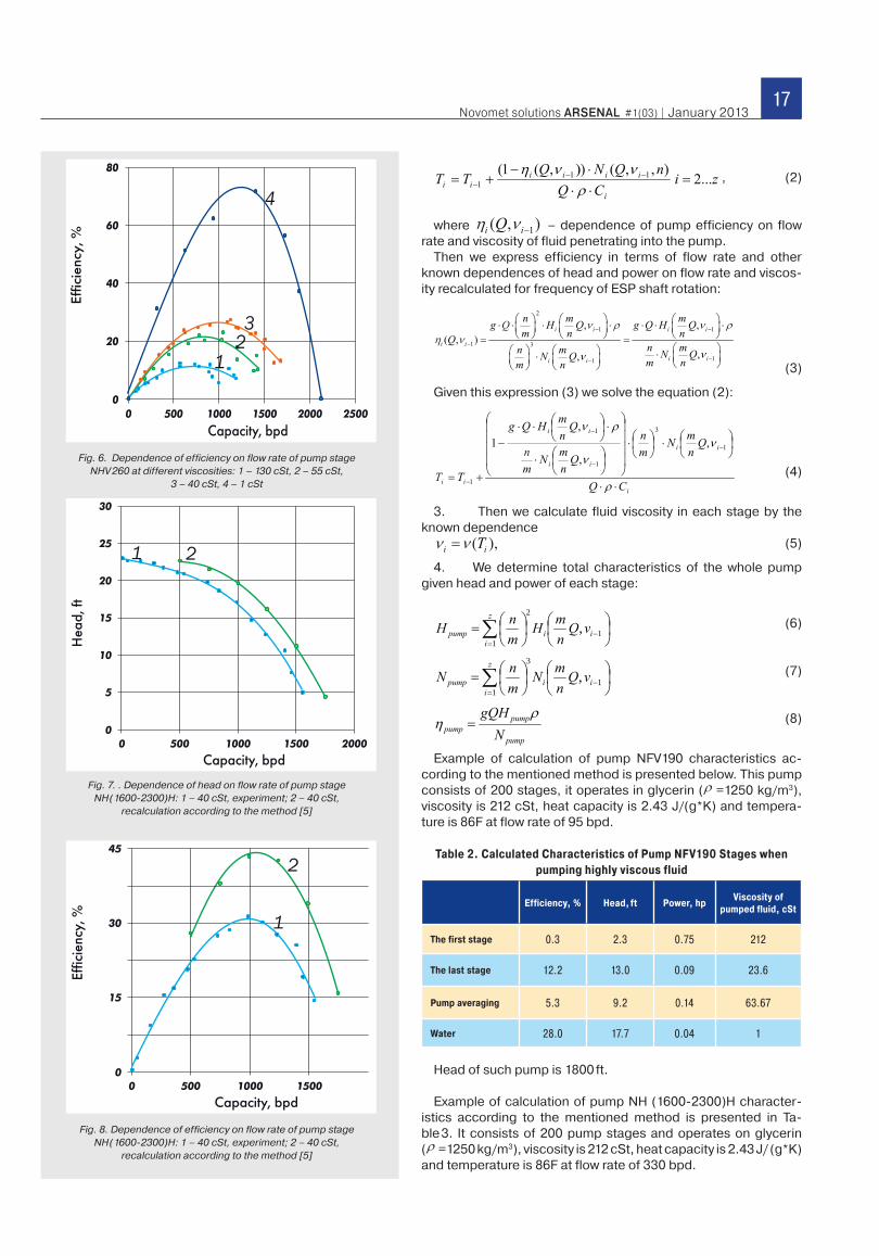
When testing generic principles for some types of pump stages were determined. The less specific speed of a pump the more decrease of efficiency, it conforms to results [1]. For example when increasing viscosity from 1 up to 40 cSt efficiency of pump stage NHV 260 decreased by five times (Fig.4). At the same time efficiency of pump stage NH (1600-2300)H decreased only by 2.7 times (Fig.6).
It is determined that viscosity does not influence on vortex ef-fect in centrifugal vortex stages operating at low and medium flow rates. Stages operating at rated flow rates of 160 bpd, 500 bpd and 790 bpd with crowns and without them were tested. Charac-teristics of corresponding stages were the same. Difference of characteristics is compatible with measurement error.
In general generic principles about change of performance of various pumps have not been traced (Fig 3, 5).
Comparison of method results [5] is presented in Fig. 7-8. In operating range calculation leads to error of 10-25%. In practice it leads to breakdown production and retrieval of ESP system.
As a result of experiments polynomial dependence of each stage characteristics on fluid viscosity has been detected. It al-lows to evaluate operating parameters of submersible pumps such as head, flow rate and consumed power when pumping well fluid in wide range of viscosity (1-400 cSt). It is confirmed that similarity laws hold valid when pumping fluid of any viscosity but accuracy is lower than that of water [1]. When increasing number of revolutions power increases less than number of revolutions raised to three and head increases more than number of revolu-tions squared.
It was also consumed that the higher viscosity is the less its harmful influence is. It means that if viscosity increases from 1 up to 20 cSt characteristics will worsen more that if viscosity increases from 20 up to 40 cSt.
Method of viscosity consideration
when selecting ESP system
During production oil is heated in a pump, its viscosity decreas-es that’s why operating characteristics of similar pump stages change according to pump length. For determination of total head and power consumption of the whole ESP system it is nec-essary to calculate operating characteristics of each pump stage.
Input calculation parameters are as follows:– characteristics of centrifugal stages obtained from high-
ly viscous fluid tests presented as dependences , , where H – head, Q – flow rate, v – viscosity of
pumped fluid, N – power of one stage, m – frequency of shaft ro-tation during testing;
– dependence of well fluid viscosity v on temperature: v = v(T).– dependence of well fluid density and heat ca-
pacity C on temperature: = (T), С = С(T) (depend-ence on temperature is weak: at Т = 40°С: / = 0.02,
С/С = 0.06);– temperature of well fluid T
1 at pump intake.
The order of calculation of pump parameters with z stages op-erating in highly viscous fluid at frequency m is as follows:
1. to determine fluid viscosity in the first stage:v
1 = v(T
1), (1)
2. to determine fluid temperature in every stage:
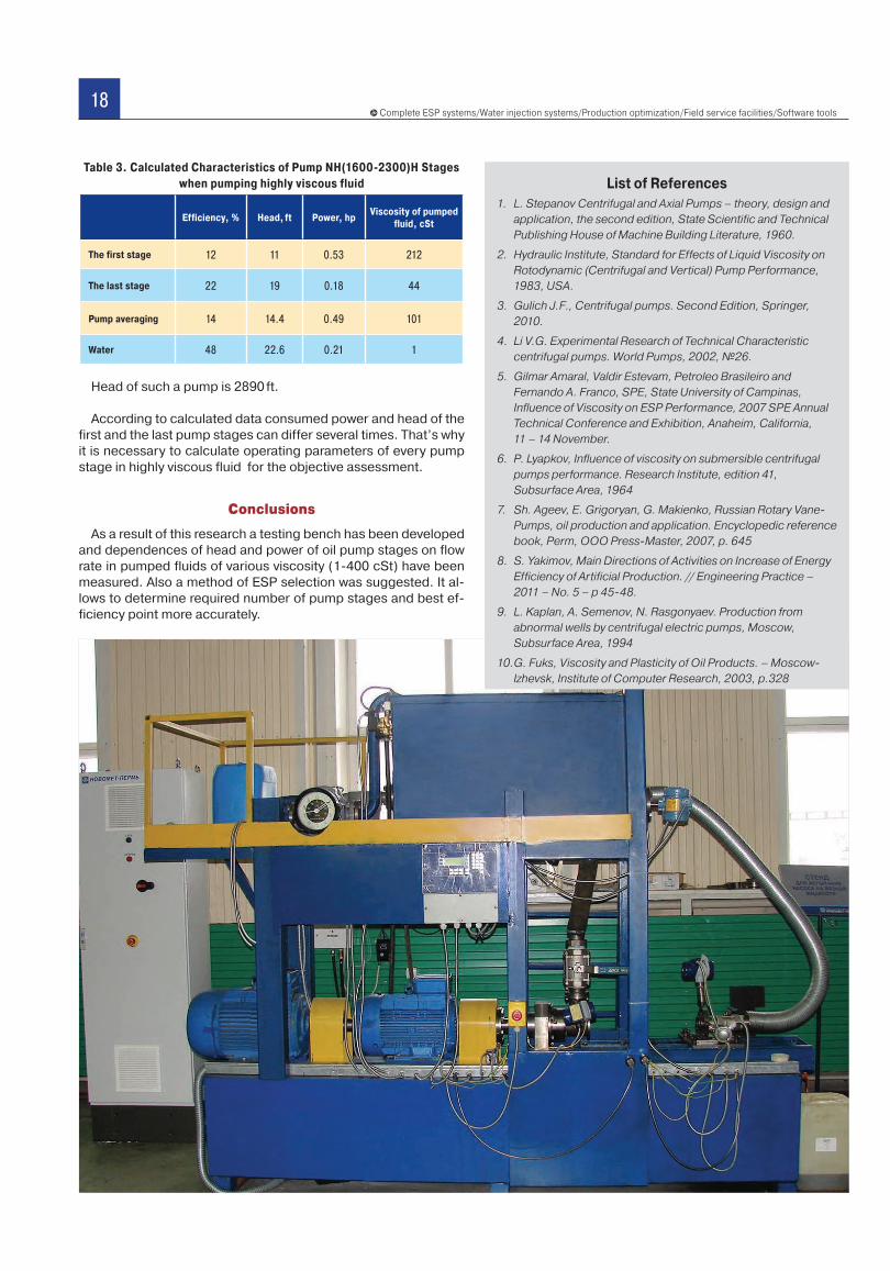
Fig. 3. Dependence of head on flow rate of pump stage NH (1600-2300)H at different viscosities: 1 – 130 cSt, 2 – 55 cSt,
3 – 40 cSt, 4 – 1 cSt
Fig. 4. Dependence of efficiency on flow rate of pump stage NH (1600-2300)H at different viscosities: 1 – 130 cSt, 2 – 55 cSt,
3 – 40 cSt, 4 – 1 cSt
Fig. 5. Dependence of head on flow rate of pump stageNHV 260 at different viscosities: 1 – 130 cSt, 2 – 55 cSt,
3 – 40 cSt, 4 – 1 cSt
17Novomet solutions ARSENAL #1(03) | January 2013
, (2)
where – dependence of pump efficiency on flow rate and viscosity of fluid penetrating into the pump.
Then we express efficiency in terms of flow rate and other known dependences of head and power on flow rate and viscos-ity recalculated for frequency of ESP shaft rotation:
(3)
Given this expression (3) we solve the equation (2):
(4)
3. Then we calculate fluid viscosity in each stage by the known dependence
(5)
4. We determine total characteristics of the whole pump given head and power of each stage:
(6)
(7)
(8)
Example of calculation of pump NFV190 characteristics ac-cording to the mentioned method is presented below. This pump consists of 200 stages, it operates in glycerin ( =1250 kg/m3), viscosity is 212 cSt, heat capacity is 2.43 J/(g*K) and tempera-ture is 86F at flow rate of 95 bpd.
Table 2. Calculated Characteristics of Pump NFV190 Stages when pumping highly viscous fluid
Efficiency, % Head, ft Power, hpViscosity of
pumped fluid, cSt
The first stage 0.3 2.3 0.75 212
The last stage 12.2 13.0 0.09 23.6
Pump averaging 5.3 9.2 0.14 63.67
Water 28.0 17.7 0.04 1
Head of such pump is 1800 ft.
Example of calculation of pump NH (1600-2300)H character-istics according to the mentioned method is presented in Ta-ble 3. It consists of 200 pump stages and operates on glycerin( =1250 kg/m3), viscosity is 212 cSt, heat capacity is 2.43 J/ (g*K) and temperature is 86F at flow rate of 330 bpd.
Fig. 6. Dependence of efficiency on flow rate of pump stage NHV 260 at different viscosities: 1 – 130 cSt, 2 – 55 cSt,
3 – 40 cSt, 4 – 1 cSt
Fig. 7. . Dependence of head on flow rate of pump stage NH (1600-2300)H: 1 – 40 cSt, experiment; 2 – 40 cSt,
recalculation according to the method [5]
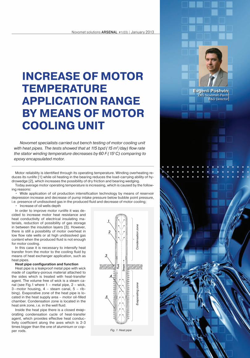
Fig. 8. Dependence of efficiency on flow rate of pump stage NH (1600-2300)H: 1 – 40 cSt, experiment; 2 – 40 cSt,
recalculation according to the method [5]
z
iiipump vQ
nmH
mnH
11
2
,
z
iiipump vQ
nmN
mnN
11
3
,
pump
pumppump N
gQH
18Complete ESP systems/Water injection systems/Production optimization/Field service facilities/Software tools
1. L. Stepanov Centrifugal and Axial Pumps – theory, design and
application, the second edition, State Scientific and Technical
Publishing House of Machine Building Literature, 1960.
2. Hydraulic Institute, Standard for Effects of Liquid Viscosity on
Rotodynamic (Centrifugal and Vertical) Pump Performance,
1983, USA.
3. Gulich J.F., Centrifugal pumps. Second Edition, Springer,
2010.
4. Li V.G. Experimental Research of Technical Characteristic
centrifugal pumps. World Pumps, 2002, №26.
5. Gilmar Amaral, Valdir Estevam, Petroleo Brasileiro and
Fernando A. Franco, SPE, State University of Campinas,
Influence of Viscosity on ESP Performance, 2007 SPE Annual
Technical Conference and Exhibition, Anaheim, California,
11 – 14 November.
6. P. Lyapkov, Influence of viscosity on submersible centrifugal
pumps performance. Research Institute, edition 41,
Subsurface Area, 1964
7. Sh. Ageev, E. Grigoryan, G. Makienko, Russian Rotary Vane-
Pumps, oil production and application. Encyclopedic reference
book, Perm, OOO Press-Master, 2007, p. 645
8. S. Yakimov, Main Directions of Activities on Increase of Energy
Efficiency of Artificial Production. // Engineering Practice –
2011 – No. 5 – p 45-48.
9. L. Kaplan, A. Semenov, N. Rasgonyaev. Production from
abnormal wells by centrifugal electric pumps, Moscow,
Subsurface Area, 1994
10. G. Fuks, Viscosity and Plasticity of Oil Products. – Moscow-
Izhevsk, Institute of Computer Research, 2003, p.328
List of ReferencesTable 3. Calculated Characteristics of Pump NH(1600-2300)H Stages
when pumping highly viscous fluid
Efficiency, % Head, ft Power, hpViscosity of pumped
fluid, cSt
The first stage 12 11 0.53 212
The last stage 22 19 0.18 44
Pump averaging 14 14.4 0.49 101
Water 48 22.6 0.21 1
Head of such a pump is 2890 ft.
According to calculated data consumed power and head of the first and the last pump stages can differ several times. That’s why it is necessary to calculate operating parameters of every pump stage in highly viscous fluid for the objective assessment.
Conclusions
As a result of this research a testing bench has been developed and dependences of head and power of oil pump stages on flow rate in pumped fluids of various viscosity (1-400 cSt) have been measured. Also a method of ESP selection was suggested. It al-lows to determine required number of pump stages and best ef-ficiency point more accurately.
19Novomet solutions ARSENAL #1(03) | January 2013
Motor reliability is identified through its operating temperature. Winding overheating re-duces its runlife [1] while oil heating in the bearing reduces the load-carrying ability of hy-drowedge [2], which increases the possibility of dry friction and bearing wedging.
Today average motor operating temperature is increasing, which is caused by the follow-ing reasons:
• Wide application of oil production intensification technology by means of reservoir depression increase and decrease of pump intake pressure below bubble point pressure, i.e. presence of undissolved gas in the produced fluid and decrease of motor cooling;
• Increase of oil wells depth
INCREASE OF MOTOR TEMPERATURE APPLICATION RANGE BY MEANS OF MOTOR COOLING UNIT
Novomet specialists carried out bench testing of motor cooling unit with heat pipes. The tests showed that at 115 bpd (15 m3/day) flow rate the stator winding temperature decreases by 60 F (15°C) comparing to epoxy encapsulated motor.
Evgenii PoshvinZAO Novomet-Perm
R&D Director
Fig. 1 Heat pipe
Co
nd
en
satio
n z
on
eE
vap
ora
ting
zo
ne
In order to improve motor runlife it was de-cided to increase motor heat resistance and heat conductivity of electrical insulating ma-terials, reduction of possibility of gas storage in between the insulation layers [3]. However, there is still a possibility of motor overheat in low flow rate wells or at high undissolved gas content when the produced fluid is not enough for motor cooling.
In this case it is necessary to intensify heat transfer from the motor to the cooling fluid by means of heat exchanger application, such as heat pipes.
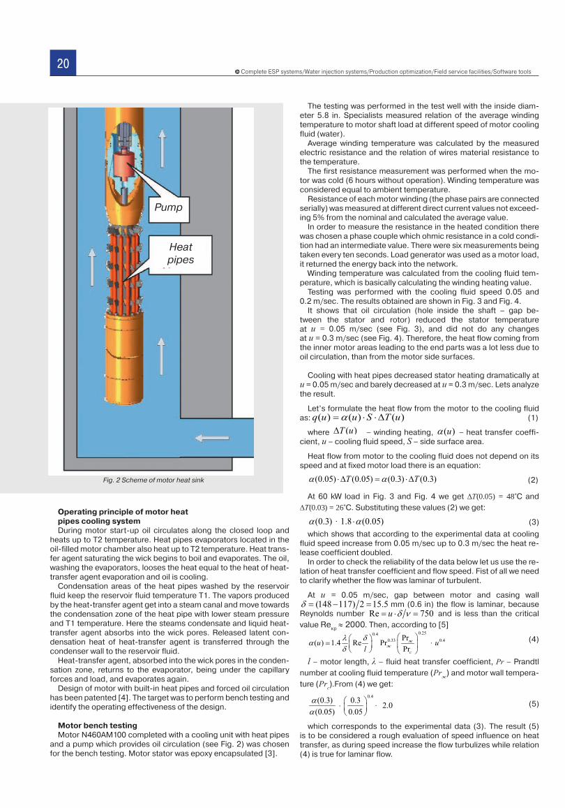
Heat pipe configuration and functionHeat pipe is a leakproof metal pipe with wick
made of capillary-porous material attached to the sides which is treated with heat-transfer agent. The volume free of wick is a steam ca-nal (see Fig.1 where 1 – metal pipe, 2 – wick, 3 – motor housing, 4 – steam canal, 5 – rib-bing). Evaporative zone of the heat pipe is lo-cated in the heat supply area – motor oil-filled chamber. Condensation zone is located in the heat sink zone, i.e. in the well fluid.
Inside the heat pipe there is a closed evap-orating condensation cycle of heat-transfer agent, which provides effective heat conduc-tivity coefficient along the axes which is 2-3 times bigger than the one of aluminium or cop-per rods.
20Complete ESP systems/Water injection systems/Production optimization/Field service facilities/Software tools
Operating principle of motor heat pipes cooling systemDuring motor start-up oil circulates along the closed loop and
heats up to T2 temperature. Heat pipes evaporators located in the oil-filled motor chamber also heat up to T2 temperature. Heat trans-fer agent saturating the wick begins to boil and evaporates. The oil, washing the evaporators, looses the heat equal to the heat of heat-transfer agent evaporation and oil is cooling.
Condensation areas of the heat pipes washed by the reservoir fluid keep the reservoir fluid temperature T1. The vapors produced by the heat-transfer agent get into a steam canal and move towards the condensation zone of the heat pipe with lower steam pressure and Т1 temperature. Here the steams condensate and liquid heat-transfer agent absorbs into the wick pores. Released latent con-densation heat of heat-transfer agent is transferred through the condenser wall to the reservoir fluid.
Heat-transfer agent, absorbed into the wick pores in the conden-sation zone, returns to the evaporator, being under the capillary forces and load, and evaporates again.
Design of motor with built-in heat pipes and forced oil circulation has been patented [4]. The target was to perform bench testing and identify the operating effectiveness of the design.
Motor bench testingMotor N460AM100 completed with a cooling unit with heat pipes
and a pump which provides oil circulation (see Fig. 2) was chosen for the bench testing. Motor stator was epoxy encapsulated [3].
The testing was performed in the test well with the inside diam-eter 5.8 in. Specialists measured relation of the average winding temperature to motor shaft load at different speed of motor cooling fluid (water).
Average winding temperature was calculated by the measured electric resistance and the relation of wires material resistance to the temperature.
The first resistance measurement was performed when the mo-tor was cold (6 hours without operation). Winding temperature was considered equal to ambient temperature.
Resistance of each motor winding (the phase pairs are connected serially) was measured at different direct current values not exceed-ing 5% from the nominal and calculated the average value.
In order to measure the resistance in the heated condition there was chosen a phase couple which ohmic resistance in a cold condi-tion had an intermediate value. There were six measurements being taken every ten seconds. Load generator was used as a motor load, it returned the energy back into the network.
Winding temperature was calculated from the cooling fluid tem-perature, which is basically calculating the winding heating value.
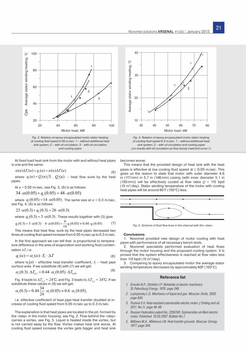
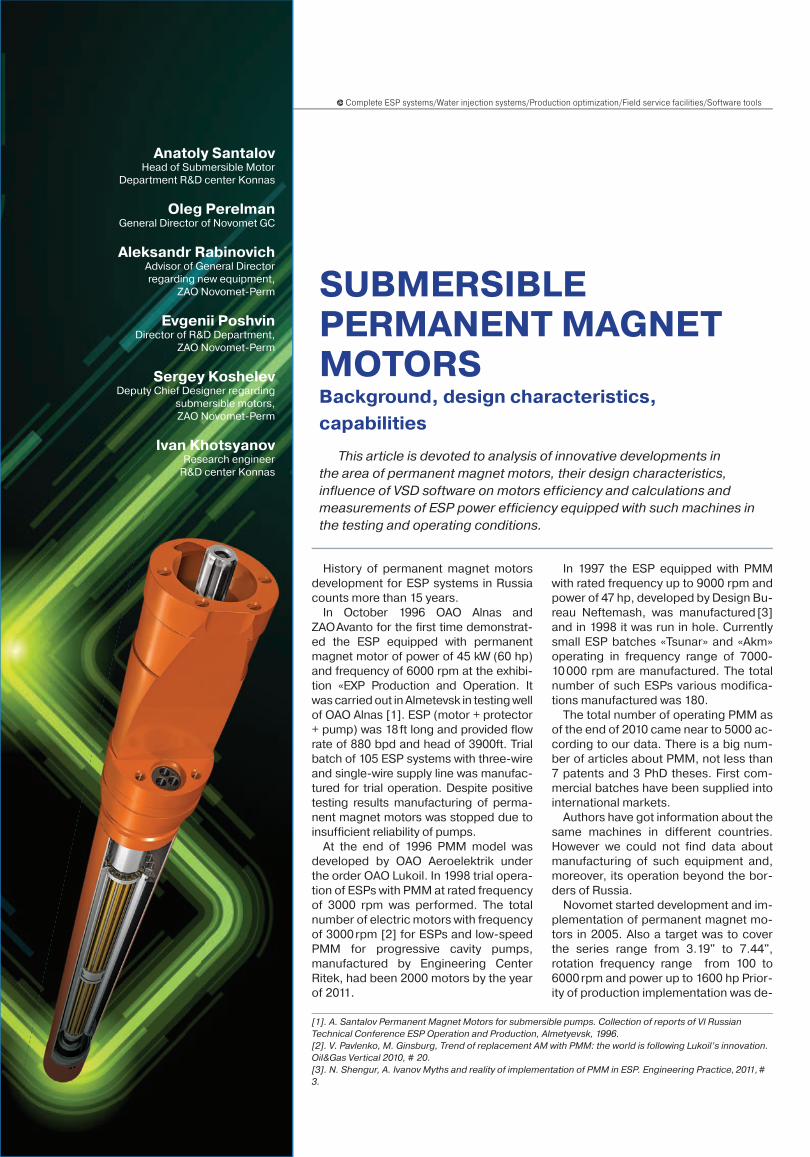
Testing was performed with the cooling fluid speed 0.05 and 0.2 m/sec. The results obtained are shown in Fig. 3 and Fig. 4.
It shows that oil circulation (hole inside the shaft – gap be-tween the stator and rotor) reduced the stator temperature at u = 0.05 m/sec (see Fig. 3), and did not do any changes at u = 0.3 m/sec (see Fig. 4). Therefore, the heat flow coming from the inner motor areas leading to the end parts was a lot less due to oil circulation, than from the motor side surfaces.
Cooling with heat pipes decreased stator heating dramatically at u = 0.05 m/sec and barely decreased at u = 0.3 m/sec. Lets analyze the result.
Let’s formulate the heat flow from the motor to the cooling fluid as: (1)
where – winding heating, – heat transfer coeffi-cient, u – cooling fluid speed, S – side surface area.
Heat flow from motor to the cooling fluid does not depend on its speed and at fixed motor load there is an equation:
(2)
At 60 kW load in Fig. 3 and Fig. 4 we get ∆T(0.05) = 48°С and
∆T(0.03) = 26°С. Substituting these values (2) we get:
(3)
which shows that according to the experimental data at cooling fluid speed increase from 0.05 m/sec up to 0.3 m/sec the heat re-lease coefficient doubled.
In order to check the reliability of the data below let us use the re-lation of heat transfer coefficient and flow speed. Fist of all we need to clarify whether the flow was laminar of turbulent.
At u = 0.05 m/sec, gap between motor and casing wall mm (0.6 in) the flow is laminar, because
Reynolds number and is less than the critical
value Reкр
≈ 2000. Then, according to [5]
(4)
l – motor length, λ – fluid heat transfer coefficient, Pr – Prandtl
number at cooling fluid temperature (Prж) and motor wall tempera-
ture (Prc).From (4) we get:
(5)
which corresponds to the experimental data (3). The result (5) is to be considered a rough evaluation of speed influence on heat transfer, as during speed increase the flow turbulizes while relation (4) is true for laminar flow.
Fig. 2 Scheme of motor heat sink
Pump
Heat pipes
21Novomet solutions ARSENAL #1(03) | January 2013
At fixed load heat sink from the motor with and without heat pipes is one and the same:
(6)
where , – heat flow sunk by the heat pipes.
At u = 0.05 m/sec, see Fig. 3, (6) is as follows:
where . The same was at u = 0.3 m/sec, see Fig. 4, (6) is as follows:
where . These results together with (3) give:
(7)
This means that heat flow, sunk by the heat pipes decreased two times at cooling fluid speed increase from 0.05 m/sec up to 0.3 m/sec.
In the first approach we can tell that is proportional to tempera-ture difference in the area of evaporation and working fluid conden-
sation ∆T, i.e.
(8)
where αt(u) – effective heat transfer coefficient, St – heat pipe surface area. If we substitute (8) with (7) we will get:
(9)
Fig. 4 leads to ∆T0.3 = 24°С, and Fig. 3 leads to ∆T0.3 = 34°С. If we substitute these values in (9) we will get:
,
i.e. effective coefficient of heat pipe heat transfer doubled at in-crease of cooling fluid speed from 0.05 m/sec up to 0.3 m/sec.
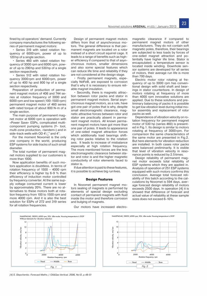
The explanation is that heat pipes are located in the pit, formed by the «step» in the motor housing, see Fig. 2. Flow behind the «step» carries a vortex, see Fig. 5. Liquid is heated inside the vortex, but is not carried away by the flow. Vortex makes heat sink worse. At cooling fluid speed increase the vortex gets bigger and heat sink
becomes worse.This means that the provided design of heat sink with the heat
pipes is effective at low cooling fluid speed ≤ 0.05 m/sec. This gives us the reason to state that motor with outer diameter 4.6 in (117 mm) in 5.7 in (146 mm) casing (with inner diameter 5.1 in (130 mm)) will be effectively cooled at flow rates Q < 115 bpd (15 m3/day). Stator winding temperature of the motor with cooling heat pipes will be around 60 F (150°C) less.
Conclusions1. Novomet provided new design of motor cooling with heat
pipes with performance of all necessary bench tests.2. Novomet specialists performed evaluation of heat flows
through the motor housing and the proposed cooling system. It is proved that the system effectiveness is reached at flow rates less than 115 bpd (15 m3/day).
3. Comparing to epoxy encapsulated motor the average stator winding temperature decreases by approximately 60F (150°C).
1. Ermolin N.P., Zhirikhin I.P. Reliability of electric machinery. St. Petersburg: Energy. 1976. page 248.
2. Loytsyansky L.G. Mechanics of liquid and gas. Moscow: Drofa. 2003. page 840.
3. Poshvin E.V. Heat-resistant submersible electric motor // Drilling and oil. 2011. No.11. page 46-49.
4. Russian Federation patent No. 2295190. Submersible oil-filled electric motor. Published: 10.03.2007. Bulletin No.7.
5. Mikheev M.A., Mikheeva I.M. Heat transfer grounds. Moscow: Energy. 1977. page 344.
Reference list
Fig. 3. Relation of epoxy encapsulated motor stator heating at cooling fluid speed 0.05 m/sec: 1 – without additional heat
sink system; 2 – with oil circulation; 3 – with oil circulation and cooling pipes
Fig. 4. Relation of epoxy encapsulated motor stator heating at cooling fluid speed 0.3 m/sec: 1 – without additional heat
sink system; 2 – with oil circulation and cooling pipes (no results with oil circulation as they barely matched curve 1)
Ave
rag
e s
tato
r w
ind
ing
he
atin
g, °
C
Motor load, kWA
vera
ge
sta
tor
win
din
g h
eat
ing
, °C
Motor load, kW
Fig. 5. Scheme of fluid flow lines in the channel with the «step»
22Complete ESP systems/Water injection systems/Production optimization/Field service facilities/Software tools
History of permanent magnet motors development for ESP systems in Russia counts more than 15 years.
In October 1996 OAO Alnas and ZAO Avanto for the first time demonstrat-ed the ESP equipped with permanent magnet motor of power of 45 kW (60 hp) and frequency of 6000 rpm at the exhibi-tion «EXP Production and Operation. It was carried out in Almetevsk in testing well of OAO Alnas [1]. ESP (motor + protector + pump) was 18 ft long and provided flow rate of 880 bpd and head of 3900ft. Trial batch of 105 ESP systems with three-wire and single-wire supply line was manufac-tured for trial operation. Despite positive testing results manufacturing of perma-nent magnet motors was stopped due to insufficient reliability of pumps.
At the end of 1996 PMM model was developed by OAO Aeroelektrik under the order OAO Lukoil. In 1998 trial opera-tion of ESPs with PMM at rated frequency of 3000 rpm was performed. The total number of electric motors with frequency of 3000 rpm [2] for ESPs and low-speed PMM for progressive cavity pumps, manufactured by Engineering Center Ritek, had been 2000 motors by the year of 2011.
SUBMERSIBLE PERMANENT MAGNET MOTORSBackground, design characteristics,
capabilities
This article is devoted to analysis of innovative developments in the area of permanent magnet motors, their design characteristics, influence of VSD software on motors efficiency and calculations and measurements of ESP power efficiency equipped with such machines in the testing and operating conditions.
In 1997 the ESP equipped with PMM with rated frequency up to 9000 rpm and power of 47 hp, developed by Design Bu-reau Neftemash, was manufactured [3] and in 1998 it was run in hole. Currently small ESP batches «Tsunar» and «Akm» operating in frequency range of 7000-10 000 rpm are manufactured. The total number of such ESPs various modifica-tions manufactured was 180.
The total number of operating PMM as of the end of 2010 came near to 5000 ac-cording to our data. There is a big num-ber of articles about PMM, not less than 7 patents and 3 PhD theses. First com-mercial batches have been supplied into international markets.
Authors have got information about the same machines in different countries. However we could not find data about manufacturing of such equipment and, moreover, its operation beyond the bor-ders of Russia.
Novomet started development and im-plementation of permanent magnet mo-tors in 2005. Also a target was to cover the series range from 3.19" to 7.44", rotation frequency range from 100 to 6000 rpm and power up to 1600 hp Prior-ity of production implementation was de-
[1]. A. Santalov Permanent Magnet Motors for submersible pumps. Collection of reports of VI Russian Technical Conference ESP Operation and Production, Almetyevsk, 1996.[2]. V. Pavlenko, M. Ginsburg, Trend of replacement AM with PMM: the world is following Lukoil’s innovation. Oil&Gas Vertical 2010, # 20.[3]. N. Shengur, A. Ivanov Myths and reality of implementation of PMM in ESP. Engineering Practice, 2011, # 3.
Anatoly SantalovHead of Submersible Motor
Department R&D center Konnas
Oleg PerelmanGeneral Director of Novomet GC
Aleksandr RabinovichAdvisor of General Director regarding new equipment,
ZAO Novomet-Perm
Evgenii PoshvinDirector of R&D Department,
ZAO Novomet-Perm
Sergey KoshelevDeputy Chief Designer regarding
submersible motors, ZAO Novomet-Perm
Ivan KhotsyanovResearch engineer
R&D center Konnas
23Novomet solutions ARSENAL #1(03) | January 2013
fined by oil operators’ demand. Currently company manufactures the following se-ries of permanent magnet motors:
• Series 319 with rated rotation fre-quency of 6000 rpm, power of up to 120 hp of a single section.
• Series 460 with rated rotation fre-quency of 3000 rpm and 6000 rpm, pow-er of up to 290 hp and 530 hp of a single section respectively.
• Series 512 with rated rotation fre-quency 3000 rpm and 6000 rpm, power of up to 400 hp and 800 hp of a single section respectively.
Preparation of production of perma-nent magnet motors of 406 and 744 se-ries at rotation frequency of 3000 and 6000 rpm and low speed (100-1500 rpm) permanent magnet motor of 460 series with rated torque of about 800 N-m of a single section.
The main purpose of permanent mag-net motor at 6000 rpm is operation with «Power Save» ESPs, complicated multi-component pumping systems (Y– tool, multi-zone production, «tandem») and in side-track wells with OD 41/
2" and 4".
For the moment Novomet is the only one company in the world, producing ESP systems for side tracks of such small diameter.
The total number of permanent mag-net motors supplied to our customers is more than 1000.
Now application benefits of such mo-tors application is doubtless. In terms of rotation frequency of 1500 – 4000 rpm their efficiency is higher by 6-9 % than efficiency of induction motor controlled by frequency converter. At the same sup-ply voltage consumed current is lower by approximately 20%. There are no al-ternatives to these motors both at rota-tion frequency from 100 to 1500 rpm and more 4000 rpm. And it is also the best solution for ESPs of 272 and 319 series for all rotation frequencies.
Design of permanent magnet motors differs from that of asynchronous mo-tors. The general difference is that per-manent magnets are located on a rotor instead of a short circuit squirrel cage. It leads to a range of benefits such as high-er efficiency if compared to that of asyn-chronous motors, smaller dimensions and also some special features which can reduce life time and reliability if they are not considered at the design stage.
• Firstly permanent magnets, espe-cially NdFeB, are exposed to corrosion that’s why it is necessary to ensure reli-able magnet insulation.
• Secondly, there is magnetic attrac-tion between rotor packs and stator in permanent magnet motors. Serial asyn-chronous magnet motors, as a rule, have got one pair of poles that is why, despite small electromagnetic clearance, mag-netic attractive forces between rotor and stator are practically absent in perma-nent magnet motors. All known perma-nent magnet motors have got more than one pair of poles. It leads to appearance of one-sided magnet attraction forces which additionally load bearings shift-ing rotor packs relative to the rotation axis. It leads to increase of misbalance especially at high rotation frequency. The more mentioned forces are the less electromagnetic clearance between sta-tor and rotor is and the higher magnetic conductivity of rotor elements faced to stator is.
If due attention is paid to these features, it is possible to achieve big run lives.
Design Features
In Novomet permanent magnet mo-tors sealing of magnets is performed by elements of special design excluding contact of permanent magnets with fluid inside the motor and therefore corrosion and bulging of magnets.
Our motors have increased electro-
magnetic clearance if compared to permanent magnet motors of other manufacturers. They do not contain soft magnetic poles, therefore, their bearings are subjected to less loads by forces of one-sided magnet attraction and po-tentially have higher life time. Stator is encapsulated; a temperature sensor is located inside winding. Downhole sen-sor systems are developed for all series of motors, their average run life is more than 700 days.
Electric motor rotor rotating at fre-quency of up to 3000 rpm has conven-tional design with solid shaft and bear-ings in stator counterbore. In design of motors rotating at frequency of more than 4000 rpm innovative solutions are applied. Due to these solutions and pre-liminary balancing of packs it is possible to get low vibration level during initial mo-tor assembly and replacement of rotor packs as well.
Dependence of vibration velocity on ro-tation frequency for permanent magnet motor of 530 hp (series 460) is present-ed in Fig.1. Its design is similar to motors rotating at frequency of 3000 rpm. For comparison the same characteristics of the same motor are presented in Fig.2. But here elements for vibration reduction are installed. In both cases rotor packs were balanced preliminarily. It is visible that level of vibration velocity in reso-nance points is reduced by 2.5 times.
Design reliability of permanent mag-net motor exceeds total reliability of ESP systems which they are applied in. Analysis of operation of 251 ESP systems equipped with such motors confirms this conclusion. Average total forecast reli-ability of this batch according to the cal-culations by Novomet is 594 days, aver-age forecast design reliability of motors exceeds 2500 days. In operation [4] it is showed that difference of forecast and actual value of reliability at these sample sizes does not exceed 6-10%.
Fig. 1 Fig. 2
[4] S. Slepchenko. Forecast Maths // Oil&Gas Vertical. 2006, No12, p.48-51
24Complete ESP systems/Water injection systems/Production optimization/Field service facilities/Software tools
Testing and Repair
Developers of permanent magnet mo-tors together with service departments of the company conducted technological analysis of special features of accept-ance tests and repair of these units, im-proved tooling and test benches. Since 2009 it allowed to test successfully and conduct current and capital repair of permanent magnet motors of full series range not only at the factory but at all service bases as well.
Here it should be mentioned that poor service can «shut down» any innovative idea. At the same time interest of ser-
vice company in successful implemen-tation allows to fully realize potential of new equipment. If we are talking about permanent magnet motors we can take results of implementation of Novomet ESP systems (319 series) as an example. ESP systems installed as of today are be-ing leased (service Novomet projects) and have average run life of 368 days. If we are talking about similar ESPs imple-mented in other projects (where service is not provided by Novomet) then aver-age run life is 91 days. Design reliability is the same, probably, interest of service companies is different.
In terms of mentioned above Novomet new equipment is planning to implement its new equipment only with its own service.
Characteristics
Operating characteristics of perma-nent magnet motors with rated frequen-cy of 3000 rpm and 6000 rpm. They are presented in Fig.4. Rated power, voltage and rotation frequency are considered as base parameters. Efficiency has an ab-solute value. Characteristics are present-ed for the most typical operating case when rotation frequency is stabilized by Novomet VSD.
Both motors have similar geometry of stator and rotor active part. So from the point of view of mechanical conversion of energy they differ only by winding pa-rameters.
Comparison of characteristics shows that motor efficiency maximum (rated rotation frequency 3000 rpm) is shifted to the left, to the area of lower loads, dif-ferently from a motor with rated rotation frequency of 6000 rpm. It allows perma-nent magnet motors with frequency of 3000 rpm to operate in a mode closest to the maximum efficiency, in a wider range of rotation frequencies than permanent magnet motors with rated rotation fre-quency of 6000 rpm.
Currently power supply to electric mo-tor is conducted according to so called 6-pulse scheme. Current switching is performed 6 times during a period in this scheme. When switching peak over-voltages occur, their amplitude exceeds double voltage of motor power supply and frequency is 6 times higher than power supply frequency. Due to over-voltage life time of transformer and ca-ble decreases and due to nonsinusoidal current additional losses occur in a mo-tor. That’s why efficiency of permanent magnet motors of well-known Russian manufacturers is 91.5%-93% according to their catalogs.
When producing latest permanent magnet motors series measures to increase efficiency were undertaken. We used electric steel of different brands, increased ratio of filling of slots with copper and also we launched Novomet VSD in August 2010. Vector control mode allowed to supply sine-wave voltage to a motor. It led to elimination of over-voltage and dramatically reduced additional losses in a motor. Besides VSD became universal, enabling to control both permanent magnet and asynchronous motors.
Fig. 3
Fig. 4
Characteristics of permanent magnet motor with rated frequency 3000 and 6000 rpm
25Novomet solutions ARSENAL #1(03) | January 2013
Measurements showed that at rotation velocity of 3000 rpm and low rated power of permanent magnet motor its efficiency increased from 93.4% and reached 94% at power of 80kVa. Efficiency of motors with frequency of 6000rpm is in the range of 92-93%. So Vector type of control al-lowed to increase efficiency by 1.7-2.5%.
When discussing at workshop it was said that increase of rotation frequency led to overheat of stator winding. That is why application of additional heat exchangers is required. In Novomet motors overheat of anchor winding does not exceed its overheat in asynchronous motors due to reasonable selection of active part geometry.
Here we are publishing data on effi-ciency and overheat of permanent mag-net motor with power of 530 hp in a single section (460 series, length is 28ft, rated rotation frequency is 6000 rpm).
Currently test bench for such power at 6000 rpm does not exist and devel-opment of this bench would require ex-tremely high costs. That’s why the mo-tor was tested on the testing well in R&D Center Konnas as a part of ESP system. During tests the load was up to 600 hp in rated mode (flow rate is 9120 bpd, head is 4920 ft, pump efficiency is 61.5%), the maximum overheat of anchor winding at lubricoolant velocity of 0.4 m/sec is 111F, average is 100F. Motor efficiency was ex-perimentally calculated. Idle mode loss-es Рim in rotation frequency function and motor temperature were measured with high accuracy when operating a motor without a protector in the air. When oper-ating motor as a part of ESP system ap-plied power Р
1, current I and motor tem-
perature were measured. Efficiency was calculated by the fol-
lowing well-known formula:
η=(Р1-Р
im-Р
c-Р
a)/Р1, (1)
where Рc = 3×I
2×R
ph – losses in copper
of anchor winding,R
ph – active resistance of phase at giv-
en temperature,Р
a – additional losses from reaction of
anchor in steel of stator, housing and ro-tor. Only this relatively small percentage (about 10%) of total losses was calcu-lated. Motor temperature was estimat-ed and checked by resistance method according to data of downhole sensor system which downhole part included a special sensor to measure winding tem-perature. Efficiency calculated by this method was 92%.
Power Saving
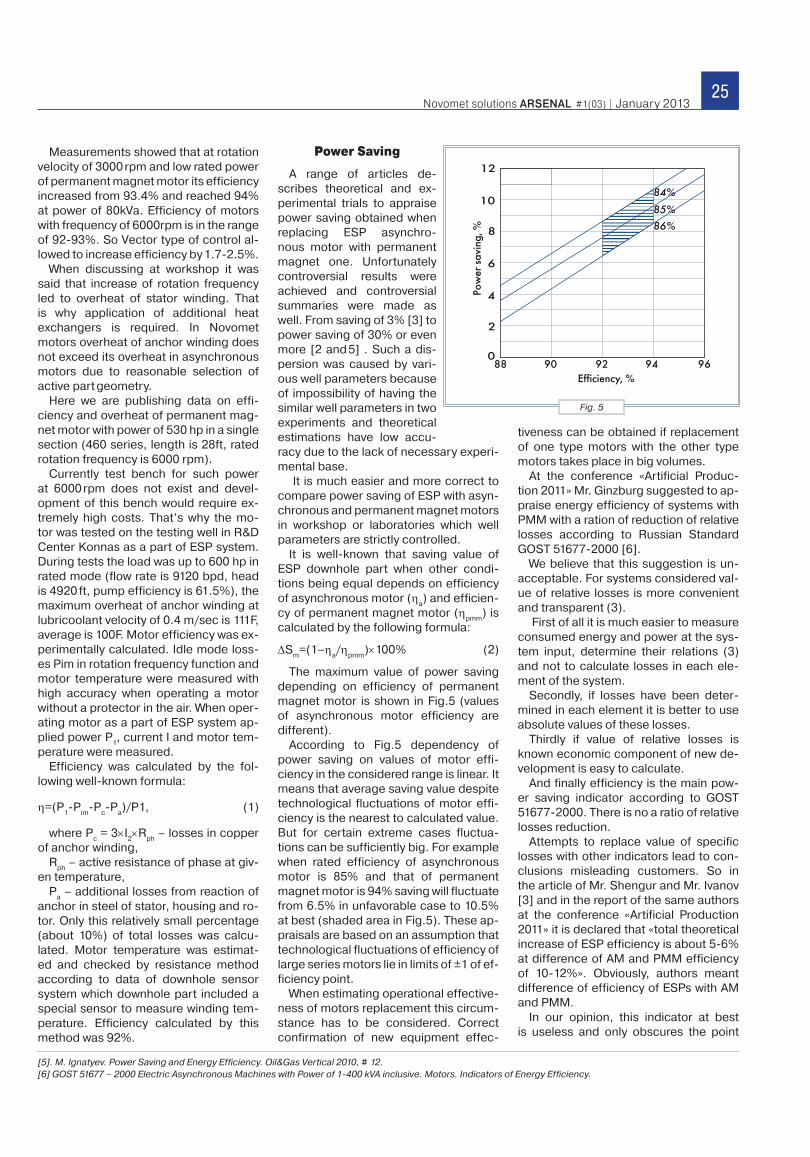
A range of articles de-scribes theoretical and ex-perimental trials to appraise power saving obtained when replacing ESP asynchro-nous motor with permanent magnet one. Unfortunately controversial results were achieved and controversial summaries were made as well. From saving of 3% [3] to power saving of 30% or even more [2 and 5] . Such a dis-persion was caused by vari-ous well parameters because of impossibility of having the similar well parameters in two experiments and theoretical estimations have low accu-racy due to the lack of necessary experi-mental base.
It is much easier and more correct to compare power saving of ESP with asyn-chronous and permanent magnet motors in workshop or laboratories which well parameters are strictly controlled.
It is well-known that saving value of ESP downhole part when other condi-tions being equal depends on efficiency of asynchronous motor (η
a) and efficien-
cy of permanent magnet motor (ηpmm
) is calculated by the following formula:
ΔSm
=(1–ηa/η
pmm)×100% (2)
The maximum value of power saving depending on efficiency of permanent magnet motor is shown in Fig.5 (values of asynchronous motor efficiency are different).
According to Fig.5 dependency of power saving on values of motor effi-ciency in the considered range is linear. It means that average saving value despite technological fluctuations of motor effi-ciency is the nearest to calculated value. But for certain extreme cases fluctua-tions can be sufficiently big. For example when rated efficiency of asynchronous motor is 85% and that of permanent magnet motor is 94% saving will fluctuate from 6.5% in unfavorable case to 10.5% at best (shaded area in Fig.5). These ap-praisals are based on an assumption that technological fluctuations of efficiency of large series motors lie in limits of ±1 of ef-ficiency point.
When estimating operational effective-ness of motors replacement this circum-stance has to be considered. Correct confirmation of new equipment effec-
tiveness can be obtained if replacement of one type motors with the other type motors takes place in big volumes.
At the conference «Artificial Produc-tion 2011» Mr. Ginzburg suggested to ap-praise energy efficiency of systems with PMM with a ration of reduction of relative losses according to Russian Standard GOST 51677-2000 [6].
We believe that this suggestion is un-acceptable. For systems considered val-ue of relative losses is more convenient and transparent (3).
First of all it is much easier to measure consumed energy and power at the sys-tem input, determine their relations (3) and not to calculate losses in each ele-ment of the system.
Secondly, if losses have been deter-mined in each element it is better to use absolute values of these losses.
Thirdly if value of relative losses is known economic component of new de-velopment is easy to calculate.
And finally efficiency is the main pow-er saving indicator according to GOST 51677-2000. There is no a ratio of relative losses reduction.
Attempts to replace value of specific losses with other indicators lead to con-clusions misleading customers. So in the article of Mr. Shengur and Mr. Ivanov [3] and in the report of the same authors at the conference «Artificial Production 2011» it is declared that «total theoretical increase of ESP efficiency is about 5-6% at difference of AM and PMM efficiency of 10-12%». Obviously, authors meant difference of efficiency of ESPs with AM and PMM.
In our opinion, this indicator at best is useless and only obscures the point
[5]. M. Ignatyev. Power Saving and Energy Efficiency. Oil&Gas Vertical 2010, # 12.[6] GOST 51677 – 2000 Electric Asynchronous Machines with Power of 1-400 kVA inclusive. Motors. Indicators of Energy Efficiency.
Fig. 5
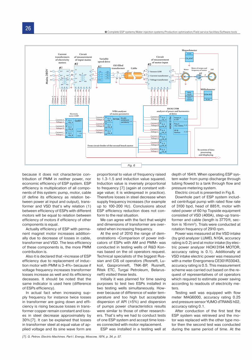
26Complete ESP systems/Water injection systems/Production optimization/Field service facilities/Software tools
because it does not characterize con-tribution of PMM in neither power, nor economic efficiency of ESP system. ESP efficiency is multiplication of all compo-nents of this system: pump, motor, cable (if define its efficiency as relation be-tween power at input and output), trans-former and VSD that’s why relation (1) between efficiency of ESPs with different motors will be equal to relation between efficiency of motors if efficiency of other components is equal.
Actually efficiency of ESP with perma-nent magnet motor increases addition-ally due to decrease of losses in cable, transformer and VSD. The less efficiency of these components is, the more PMM contribution is.
Also it is declared that «increase of ESP efficiency due to replacement of induc-tion motor with PMM is 3-4%» because if voltage frequency increases transformer losses increase as well and its efficiency deceases. It should be noted that the same indicator is used here (difference of ESPs efficiency).
In actual fact when increasing sup-ply frequency for instance twice losses in transformer are going down and effi-ciency is rising because losses in trans-former copper remain constant and loss-es in steel decrease approximately by 30% [7]. It can be explained that losses in transformer steel at equal value of ap-plied voltage and its sine wave form are
proportional to value of frequency raised to 1.3-1.5 and induction value squared. Induction value is inversely proportional to frequency [7] (again at constant volt-age value; it is widespread in practice). Therefore losses in steel decrease when supply frequency increases (for example up to 100-200 Hz). Conclusions about ESP efficiency reduction does not con-form to the real situation.
We can agree with the fact that weight and dimensions of transformer are over-rated when increasing frequency.
At the end of 2010 the range of dem-onstrations «Comparison of power indi-cators of ESPs with AM and PMM» was conducted in testing wells of R&D Kon-nas based on the oil operators request. Technical specialists of the biggest Rus-sian and CIS oil operators (Rosneft, Lu-koil, Gaspromneft, TNK-BP, Rusneft, Ritek ETC, Turgai Petroleum, Belarus-neft) visited these tests.
Initially it was planned for time saving purposes to test two ESPs installed in two testing wells simultaneously. How-ever because of difference of water tem-perature and too high but acceptable dispersion of API (±5%) and dispersion of pumps power characteristics results were similar to those of other research-ers. That’s why we had to conduct tests of one ESP system and accept time loss-es connected with motor replacement.
ESP was installed in a testing well at
depth of 164 ft. When operating ESP sys-tem water from pump discharge through tubing flowed to a tank through flow and pressure metering system.
Electric circuit is presented in Fig.6.Downhole part of ESP system includ-
ed centrifugal pump with rated flow rate of 3100 bpd, head of 885 ft, motor with rated power of 60 hp Topside equipment consisted of VSD (400A), step-up trans-former and cable (length is 3770 ft, sec-tion is 16 mm2). Trials were conducted at rotation frequency of 2910 rpm.
Power was measured at the VSD intake (by grid analyzer LUMEL N10A, accuracy rating is 0.2) and at motor intake (by elec-tric power analyzer HiOKI 3194 MOTOR, accuracy rating is 0.1). Additionally at VSD intake electric power was measured with a meter Energomera CE301R33043, accuracy rating is 0.5. This measurement scheme was carried out based on the re-quest of representatives of oil operators which required to estimate power saving according to readouts of electricity me-ters.
Testing well was equipped with flow meter MAG6000, accuracy rating 0.25 and pressure sensor YUMO dTRANS h02, accuracy rating 0.1.
After conduction of the first test the ESP system was retrieved and the mo-tor was replaced with the other type mo-tor then the second test was conducted during the same period of time. At the
Fig. 6
[7]. G. Petrov. Electric Machines. Part I. Energy, Moscow, 1974, p. 34, p. 57.
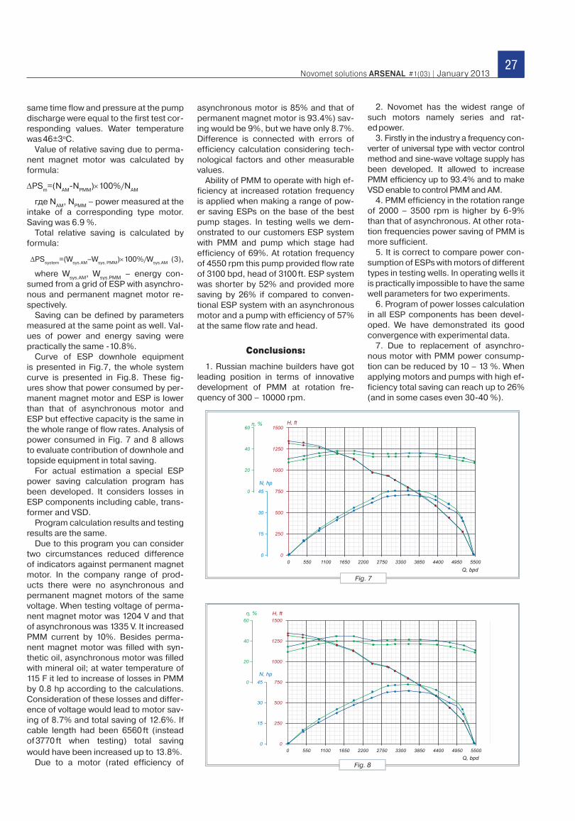
27Novomet solutions ARSENAL #1(03) | January 2013
same time flow and pressure at the pump discharge were equal to the first test cor-responding values. Water temperature was 46±3оС.
Value of relative saving due to perma-nent magnet motor was calculated by formula:
ΔPSm
=(NAM
-NPMM
)×100%/NAM
где NAM
, NPMM
– power measured at the intake of a corresponding type motor. Saving was 6.9 %.
Total relative saving is calculated by formula:
ΔPSsystem
=(Wsys.AM
–Wsys. PMM
)×100%/Wsys.AM
(3),
where Wsys.AM
, Wsys.PMM
– energy con-sumed from a grid of ESP with asynchro-nous and permanent magnet motor re-spectively.
Saving can be defined by parameters measured at the same point as well. Val-ues of power and energy saving were practically the same -10.8%.
Curve of ESP downhole equipment is presented in Fig.7, the whole system curve is presented in Fig.8. These fig-ures show that power consumed by per-manent magnet motor and ESP is lower than that of asynchronous motor and ESP but effective capacity is the same in the whole range of flow rates. Analysis of power consumed in Fig. 7 and 8 allows to evaluate contribution of downhole and topside equipment in total saving.
For actual estimation a special ESP power saving calculation program has been developed. It considers losses in ESP components including cable, trans-former and VSD.
Program calculation results and testing results are the same.
Due to this program you can consider two circumstances reduced difference of indicators against permanent magnet motor. In the company range of prod-ucts there were no asynchronous and permanent magnet motors of the same voltage. When testing voltage of perma-nent magnet motor was 1204 V and that of asynchronous was 1335 V. It increased PMM current by 10%. Besides perma-nent magnet motor was filled with syn-thetic oil, asynchronous motor was filled with mineral oil; at water temperature of 115 F it led to increase of losses in PMM by 0.8 hp according to the calculations. Consideration of these losses and differ-ence of voltage would lead to motor sav-ing of 8.7% and total saving of 12.6%. If cable length had been 6560 ft (instead of 3770 ft when testing) total saving would have been increased up to 13.8%.
Due to a motor (rated efficiency of
asynchronous motor is 85% and that of permanent magnet motor is 93.4%) sav-ing would be 9%, but we have only 8.7%. Difference is connected with errors of efficiency calculation considering tech-nological factors and other measurable values.
Ability of PMM to operate with high ef-ficiency at increased rotation frequency is applied when making a range of pow-er saving ESPs on the base of the best pump stages. In testing wells we dem-onstrated to our customers ESP system with PMM and pump which stage had efficiency of 69%. At rotation frequency of 4550 rpm this pump provided flow rate of 3100 bpd, head of 3100 ft. ESP system was shorter by 52% and provided more saving by 26% if compared to conven-tional ESP system with an asynchronous motor and a pump with efficiency of 57% at the same flow rate and head.
Conclusions:
1. Russian machine builders have got leading position in terms of innovative development of PMM at rotation fre-quency of 300 – 10000 rpm.
2. Novomet has the widest range of such motors namely series and rat-ed power.
3. Firstly in the industry a frequency con-verter of universal type with vector control method and sine-wave voltage supply has been developed. It allowed to increase PMM efficiency up to 93.4% and to make VSD enable to control PMM and AM.
4. PMM efficiency in the rotation range of 2000 – 3500 rpm is higher by 6-9% than that of asynchronous. At other rota-tion frequencies power saving of PMM is more sufficient.
5. It is correct to compare power con-sumption of ESPs with motors of different types in testing wells. In operating wells it is practically impossible to have the same well parameters for two experiments.
6. Program of power losses calculation in all ESP components has been devel-oped. We have demonstrated its good convergence with experimental data.
7. Due to replacement of asynchro-nous motor with PMM power consump-tion can be reduced by 10 – 13 %. When applying motors and pumps with high ef-ficiency total saving can reach up to 26% (and in some cases even 30-40 %).
Fig. 7
Fig. 8
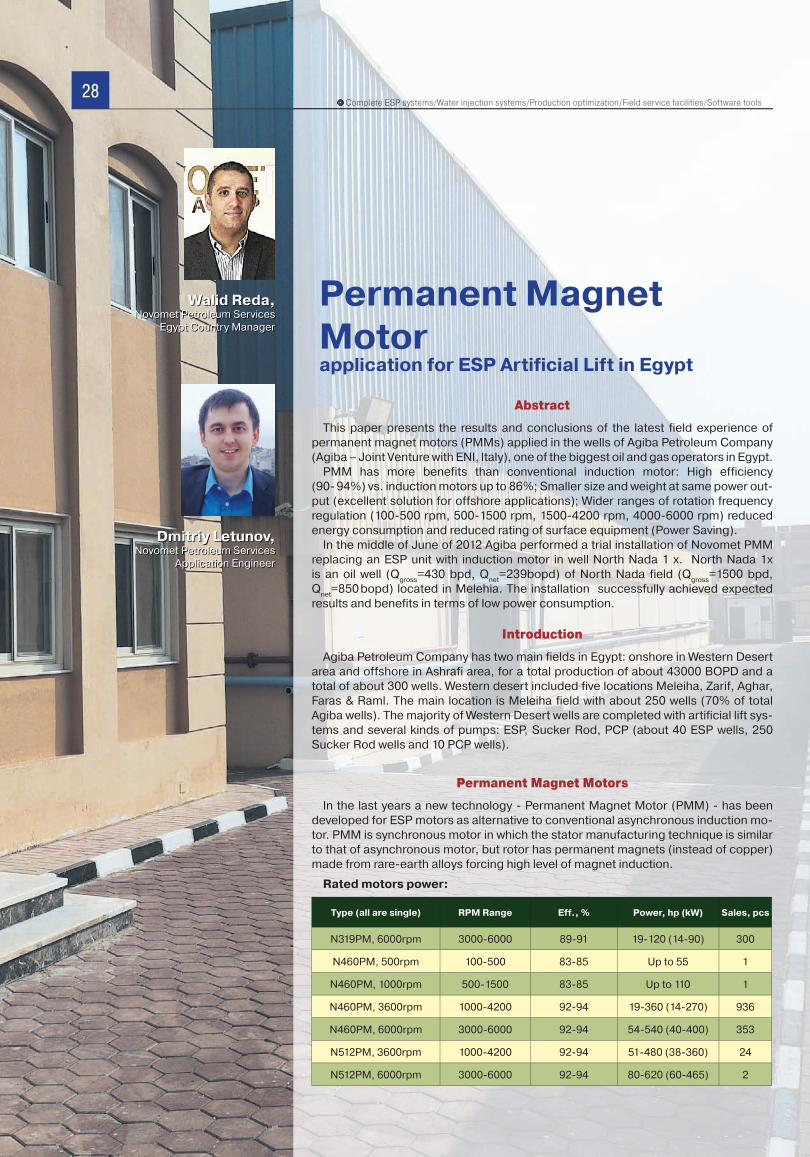
28Complete ESP systems/Water injection systems/Production optimization/Field service facilities/Software toolsComComComComComComomoComComommCo pleplepleplepleplellelepleplelpleette teteetete tteetettt ESPESPESPESPESESPESPESPESPESPESPEESPESP sysysysysysyss stes ms/Water injection systems/Production optimization/Field service facilities/Software tools
Abstract
This paper presents the results and conclusions of the latest field experience of permanent magnet motors (PMMs) applied in the wells of Agiba Petroleum Company (Agiba – Joint Venture with ENI, Italy), one of the biggest oil and gas operators in Egypt.
PMM has more benefits than conventional induction motor: High efficiency (90- 94%) vs. induction motors up to 86%; Smaller size and weight at same power out-put (excellent solution for offshore applications); Wider ranges of rotation frequency regulation (100-500 rpm, 500-1500 rpm, 1500-4200 rpm, 4000-6000 rpm) reduced energy consumption and reduced rating of surface equipment (Power Saving).
In the middle of June of 2012 Agiba performed a trial installation of Novomet PMM replacing an ESP unit with induction motor in well North Nada 1 x. North Nada 1x is an oil well (Q
gross=430 bpd, Q
net=239bopd) of North Nada field (Q
gross=1500 bpd,
Qnet
=850 bopd) located in Melehia. The installation successfully achieved expected results and benefits in terms of low power consumption.
Introduction
Agiba Petroleum Company has two main fields in Egypt: onshore in Western Desert area and offshore in Ashrafi area, for a total production of about 43000 BOPD and a total of about 300 wells. Western desert included five locations Meleiha, Zarif, Aghar, Faras & Raml. The main location is Meleiha field with about 250 wells (70% of total Agiba wells). The majority of Western Desert wells are completed with artificial lift sys-tems and several kinds of pumps: ESP, Sucker Rod, PCP (about 40 ESP wells, 250 Sucker Rod wells and 10 PCP wells).
Permanent Magnet Motors
In the last years a new technology - Permanent Magnet Motor (PMM) - has been developed for ESP motors as alternative to conventional asynchronous induction mo-tor. PMM is synchronous motor in which the stator manufacturing technique is similar to that of asynchronous motor, but rotor has permanent magnets (instead of copper) made from rare-earth alloys forcing high level of magnet induction.
Rated motors power:
Permanent Magnet Motorapplication for ESP Artificial Lift in Egypt
Walid Reda,Novomet Petroleum Services
Egypt Country Manager
Dmitriy Letunov,
Novomet Petroleum Services Application Engineer
Type (all are single) RPM Range Eff., % Power, hp (kW) Sales, pcs
N319PM, 6000rpm 3000-6000 89-91 19-120 (14-90) 300
N460PM, 500rpm 100-500 83-85 Up to 55 1
N460PM, 1000rpm 500-1500 83-85 Up to 110 1
N460PM, 3600rpm 1000-4200 92-94 19-360 (14-270) 936
N460PM, 6000rpm 3000-6000 92-94 54-540 (40-400) 353
N512PM, 3600rpm 1000-4200 92-94 51-480 (38-360) 24
N512PM, 6000rpm 3000-6000 92-94 80-620 (60-465) 2
28
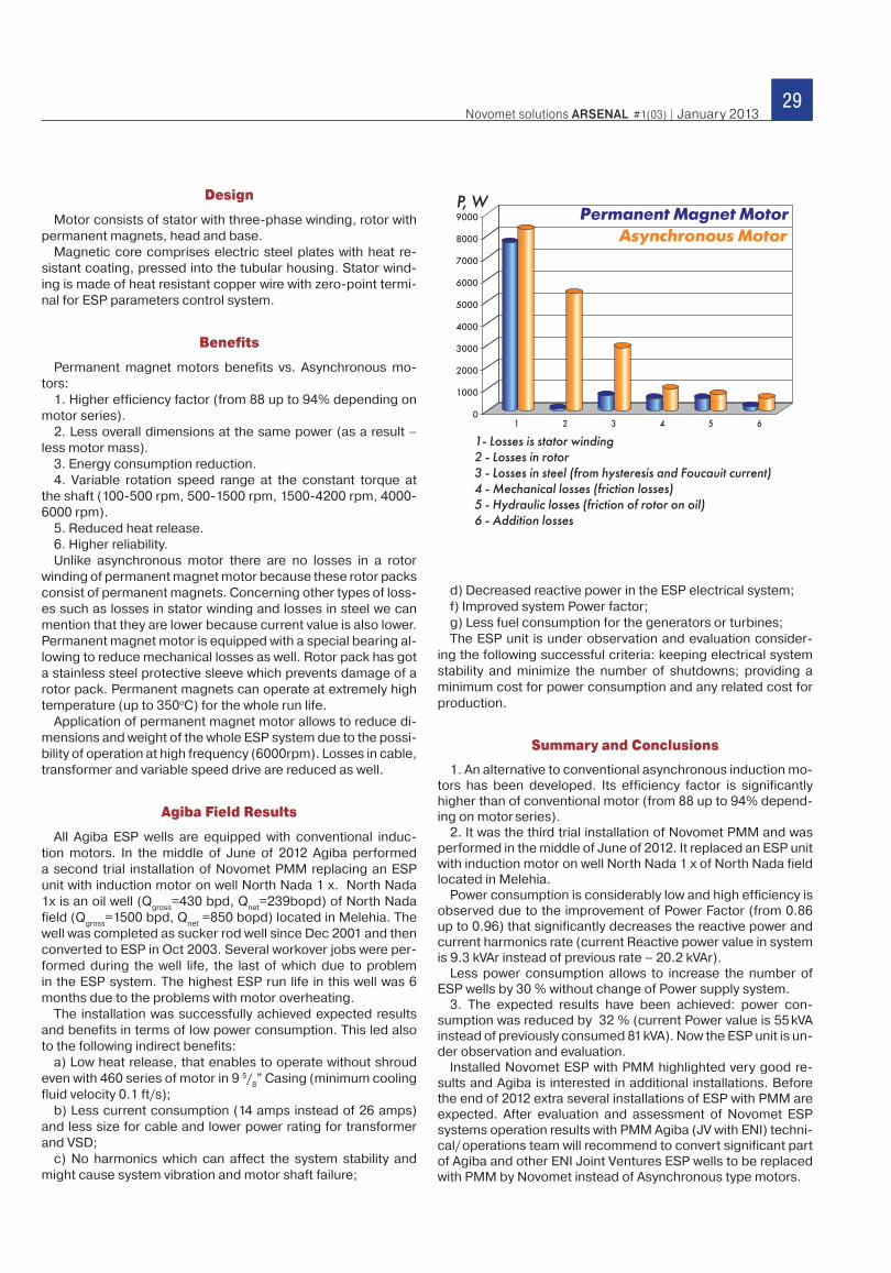
29Novomet solutions ARSENAL #1(03) | January 2013
Design
Motor consists of stator with three-phase winding, rotor with permanent magnets, head and base.
Magnetic core comprises electric steel plates with heat re-sistant coating, pressed into the tubular housing. Stator wind-ing is made of heat resistant copper wire with zero-point termi-nal for ESP parameters control system.
Benefits
Permanent magnet motors benefits vs. Asynchronous mo-tors:
1. Higher efficiency factor (from 88 up to 94% depending on motor series).
2. Less overall dimensions at the same power (as a result – less motor mass).
3. Energy consumption reduction.4. Variable rotation speed range at the constant torque at
the shaft (100-500 rpm, 500-1500 rpm, 1500-4200 rpm, 4000-6000 rpm).
5. Reduced heat release.6. Higher reliability.Unlike asynchronous motor there are no losses in a rotor
winding of permanent magnet motor because these rotor packs consist of permanent magnets. Concerning other types of loss-es such as losses in stator winding and losses in steel we can mention that they are lower because current value is also lower. Permanent magnet motor is equipped with a special bearing al-lowing to reduce mechanical losses as well. Rotor pack has got a stainless steel protective sleeve which prevents damage of a rotor pack. Permanent magnets can operate at extremely high temperature (up to 350oC) for the whole run life.
Application of permanent magnet motor allows to reduce di-mensions and weight of the whole ESP system due to the possi-bility of operation at high frequency (6000rpm). Losses in cable, transformer and variable speed drive are reduced as well.
Agiba Field Results
All Agiba ESP wells are equipped with conventional induc-tion motors. In the middle of June of 2012 Agiba performed a second trial installation of Novomet PMM replacing an ESP unit with induction motor on well North Nada 1 x. North Nada 1x is an oil well (Q
gross=430 bpd, Q
net=239bopd) of North Nada
field (Qgross
=1500 bpd, Qnet
=850 bopd) located in Melehia. The well was completed as sucker rod well since Dec 2001 and then converted to ESP in Oct 2003. Several workover jobs were per-formed during the well life, the last of which due to problem in the ESP system. The highest ESP run life in this well was 6 months due to the problems with motor overheating.
The installation was successfully achieved expected results and benefits in terms of low power consumption. This led also to the following indirect benefits:
a) Low heat release, that enables to operate without shroud even with 460 series of motor in 9 5/
8” Casing (minimum cooling
fluid velocity 0.1 ft/s); b) Less current consumption (14 amps instead of 26 amps)
and less size for cable and lower power rating for transformer and VSD;
c) No harmonics which can affect the system stability and might cause system vibration and motor shaft failure;
d) Decreased reactive power in the ESP electrical system; f) Improved system Power factor; g) Less fuel consumption for the generators or turbines; The ESP unit is under observation and evaluation consider-
ing the following successful criteria: keeping electrical system stability and minimize the number of shutdowns; providing a minimum cost for power consumption and any related cost for production.
Summary and Conclusions
1. An alternative to conventional asynchronous induction mo-tors has been developed. Its efficiency factor is significantly higher than of conventional motor (from 88 up to 94% depend-ing on motor series).
2. It was the third trial installation of Novomet PMM and was performed in the middle of June of 2012. It replaced an ESP unit with induction motor on well North Nada 1 x of North Nada field located in Melehia.
Power consumption is considerably low and high efficiency is observed due to the improvement of Power Factor (from 0.86 up to 0.96) that significantly decreases the reactive power and current harmonics rate (current Reactive power value in system is 9.3 kVAr instead of previous rate – 20.2 kVAr).
Less power consumption allows to increase the number of ESP wells by 30 % without change of Power supply system.
3. The expected results have been achieved: power con-sumption was reduced by 32 % (current Power value is 55 kVA instead of previously consumed 81 kVA). Now the ESP unit is un-der observation and evaluation.
Installed Novomet ESP with PMM highlighted very good re-sults and Agiba is interested in additional installations. Before the end of 2012 extra several installations of ESP with PMM are expected. After evaluation and assessment of Novomet ESP systems operation results with PMM Agiba (JV with ENI) techni-cal/ operations team will recommend to convert significant part of Agiba and other ENI Joint Ventures ESP wells to be replaced with PMM by Novomet instead of Asynchronous type motors.
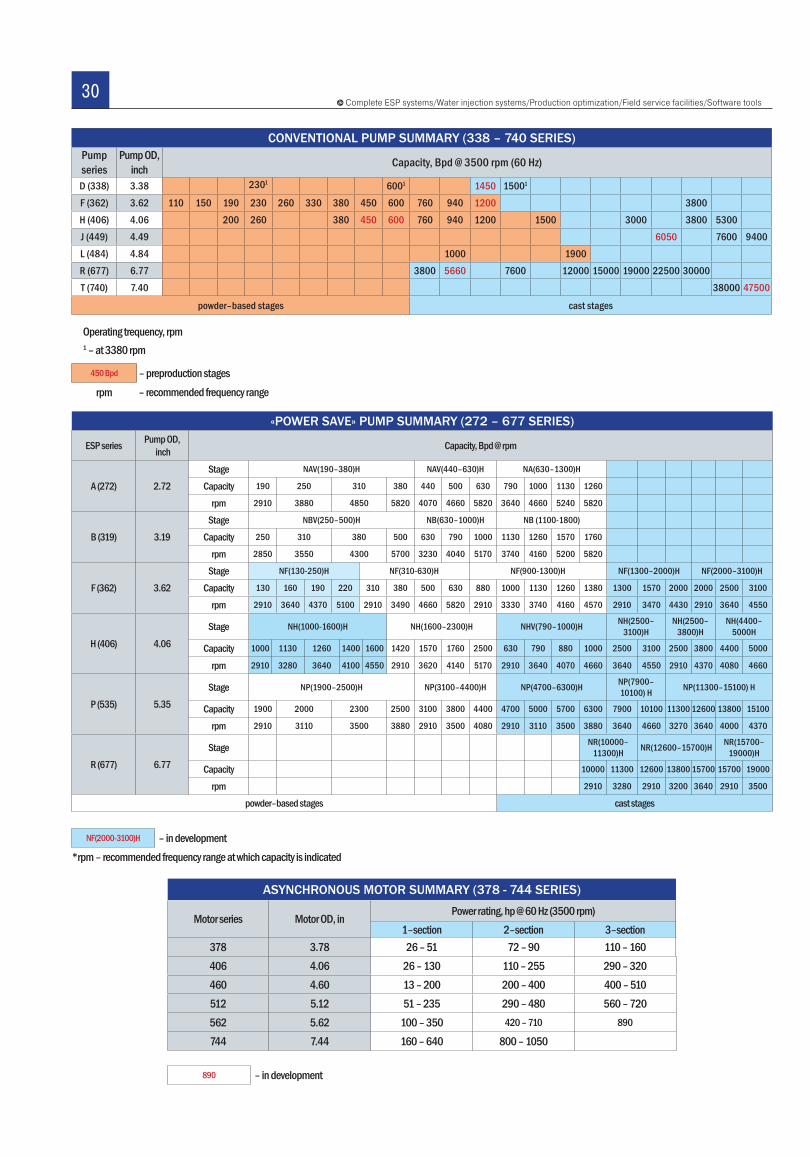
30Complete ESP systems/Water injection systems/Production optimization/Field service facilities/Software tools
ASYNCHRONOUS MOTOR SUMMARY (378 - 744 SERIES)
Motor series Motor OD, inPower rating, hp @ 60 Hz (3500 rpm)
1–section 2–section 3–section378 3.78 26 – 51 72 – 90 110 – 160406 4.06 26 – 130 110 – 255 290 – 320460 4.60 13 – 200 200 – 400 400 – 510512 5.12 51 – 235 290 – 480 560 – 720562 5.62 100 – 350 420 – 710 890
744 7.44 160 – 640 800 – 1050
890 – in development
«POWER SAVE» PUMP SUMMARY (272 – 677 SERIES)
ESP series Pump OD, inch Capacity, Bpd @ rpm
А (272) 2.72Stage NAV(190–380)H NAV(440–630)H NA(630–1300)H
Capacity 190 250 310 380 440 500 630 790 1000 1130 1260
rpm 2910 3880 4850 5820 4070 4660 5820 3640 4660 5240 5820
B (319) 3.19Stage NBV(250–500)H NB(630–1000)H NB (1100-1800)
Capacity 250 310 380 500 630 790 1000 1130 1260 1570 1760
rpm 2850 3550 4300 5700 3230 4040 5170 3740 4160 5200 5820
F (362) 3.62Stage NF(130-250)Н NF(310-630)Н NF(900-1300)Н NF(1300–2000)H NF(2000–3100)H
Capacity 130 160 190 220 310 380 500 630 880 1000 1130 1260 1380 1300 1570 2000 2000 2500 3100
rpm 2910 3640 4370 5100 2910 3490 4660 5820 2910 3330 3740 4160 4570 2910 3470 4430 2910 3640 4550
H (406) 4.06Stage NH(1000-1600)Н NH(1600–2300)Н NHV(790–1000)Н NH(2500–
3100)НNH(2500–
3800)НNH(4400–
5000H
Capacity 1000 1130 1260 1400 1600 1420 1570 1760 2500 630 790 880 1000 2500 3100 2500 3800 4400 5000
rpm 2910 3280 3640 4100 4550 2910 3620 4140 5170 2910 3640 4070 4660 3640 4550 2910 4370 4080 4660
P (535) 5.35Stage NP(1900–2500)H NP(3100–4400)H NP(4700–6300)Н NP(7900–
10100) Н NP(11300–15100) Н
Capacity 1900 2000 2300 2500 3100 3800 4400 4700 5000 5700 6300 7900 10100 11300 12600 13800 15100
rpm 2910 3110 3500 3880 2910 3500 4080 2910 3110 3500 3880 3640 4660 3270 3640 4000 4370
R (677) 6.77Stage NR(10000–
11300)Н NR(12600–15700)Н NR(15700–19000)Н
Capacity 10000 11300 12600 13800 15700 15700 19000
rpm 2910 3280 2910 3200 3640 2910 3500
powder–based stages cast stages
NF(2000-3100)H – in development*rpm – recommended frequency range at which capacity is indicated
CONVENTIONAL PUMP SUMMARY (338 – 740 SERIES)Pump series
Pump OD, inch Capacity, Bpd @ 3500 rpm (60 Hz)
D (338) 3.38 2301 6001 1450 15001
F (362) 3.62 110 150 190 230 260 330 380 450 600 760 940 1200 3800H (406) 4.06 200 260 380 450 600 760 940 1200 1500 3000 3800 5300J (449) 4.49 6050 7600 9400L (484) 4.84 1000 1900R (677) 6.77 3800 5660 7600 12000 15000 19000 22500 30000T (740) 7.40 38000 47500
powder–based stages cast stages
Operating trequency, rpm1 – at 3380 rpm
450 Bpd – preproduction stagesrpm – recommended frequency range
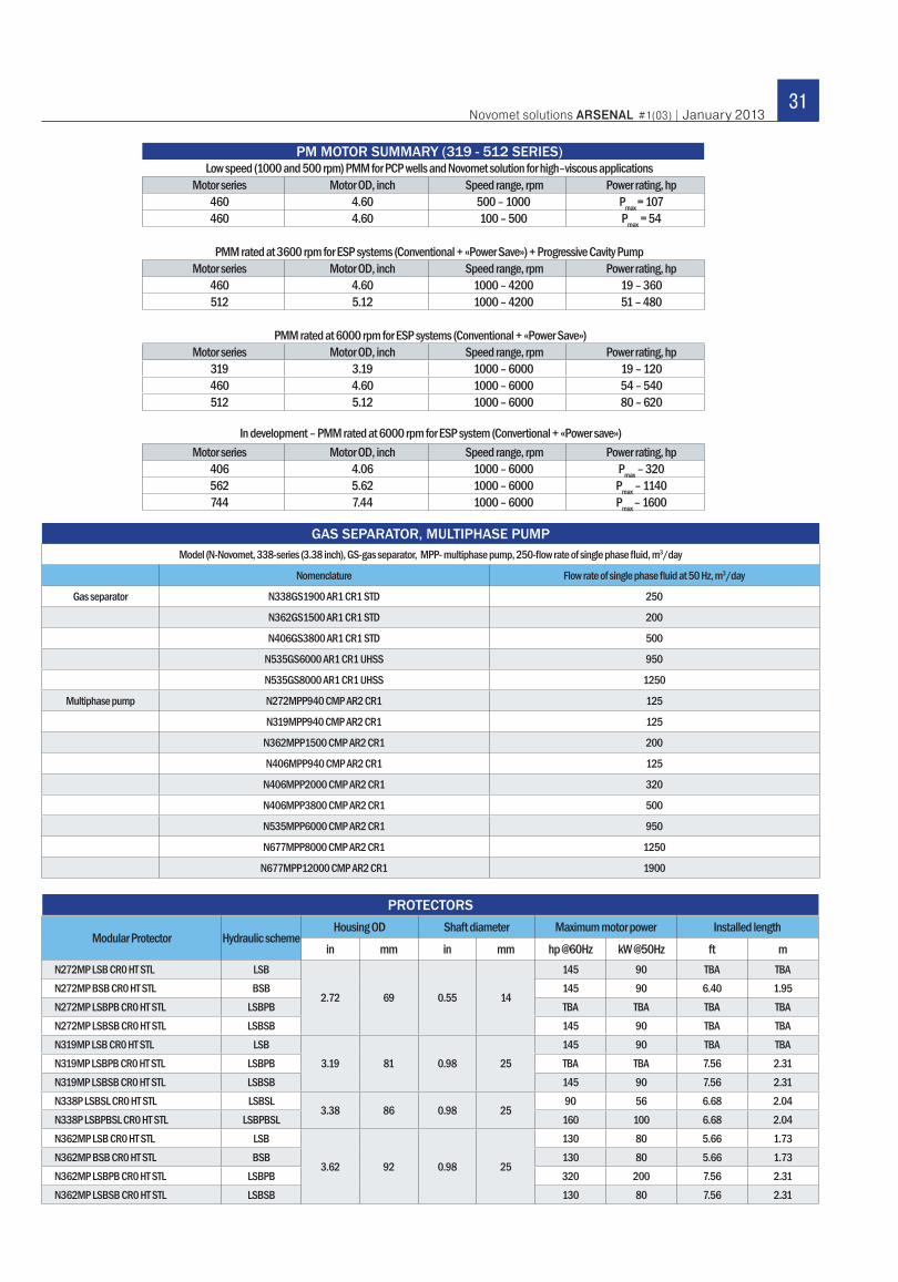
31Novomet solutions ARSENAL #1(03) | January 2013
PM MOTOR SUMMARY (319 - 512 SERIES)Low speed (1000 and 500 rpm) PMM for PCP wells and Novomet solution for high–viscous applications
Motor series Motor OD, inch Speed range, rpm Power rating, hp460 4.60 500 – 1000 Pmax = 107460 4.60 100 – 500 Pmax = 54
PMM rated at 3600 rpm for ESP systems (Conventional + «Power Save») + Progressive Cavity PumpMotor series Motor OD, inch Speed range, rpm Power rating, hp
460 4.60 1000 – 4200 19 – 360512 5.12 1000 – 4200 51 – 480
PMM rated at 6000 rpm for ESP systems (Conventional + «Power Save»)Motor series Motor OD, inch Speed range, rpm Power rating, hp
319 3.19 1000 – 6000 19 – 120460 4.60 1000 – 6000 54 – 540512 5.12 1000 – 6000 80 – 620
In development – PMM rated at 6000 rpm for ESP system (Convertional + «Power save»)Motor series Motor OD, inch Speed range, rpm Power rating, hp
406 4.06 1000 – 6000 Pmax – 320562 5.62 1000 – 6000 Pmax – 1140744 7.44 1000 – 6000 Pmax – 1600
GAS SEPARATOR, MULTIPHASE PUMPModel (N-Novomet, 338-series (3.38 inch), GS-gas separator, MPP- multiphase pump, 250-fl ow rate of single phase fl uid, m3/day
Nomenclature Flow rate of single phase fl uid at 50 Hz, m3/day
Gas separator N338GS1900 AR1 CR1 STD 250
N362GS1500 AR1 CR1 STD 200
N406GS3800 AR1 CR1 STD 500
N535GS6000 AR1 CR1 UHSS 950
N535GS8000 AR1 CR1 UHSS 1250
Multiphase pump N272MPP940 CMP AR2 CR1 125
N319MPP940 CMP AR2 CR1 125
N362MPP1500 CMP AR2 CR1 200
N406MPP940 CMP AR2 CR1 125
N406MPP2000 CMP AR2 CR1 320
N406MPP3800 CMP AR2 CR1 500
N535MPP6000 CMP AR2 CR1 950
N677MPP8000 CMP AR2 CR1 1250
N677MPP12000 CMP AR2 CR1 1900
Modular Protector Hydraulic schemeHousing OD Shaft diameter Maximum motor power Installed length
in mm in mm hp @60Hz kW @50Hz ft mN272MP LSB CR0 HT STL LSB
2.72 69 0.55 14
145 90 TBA TBAN272MP BSB CR0 HT STL BSB 145 90 6.40 1.95N272MP LSBPB CR0 HT STL LSBPB TBA TBA TBA TBAN272MP LSBSB CR0 HT STL LSBSB 145 90 TBA TBAN319MP LSB CR0 HT STL LSB
3.19 81 0.98 25145 90 TBA TBA
N319MP LSBPB CR0 HT STL LSBPB TBA TBA 7.56 2.31N319MP LSBSB CR0 HT STL LSBSB 145 90 7.56 2.31N338P LSBSL CR0 HT STL LSBSL
3.38 86 0.98 2590 56 6.68 2.04
N338P LSBPBSL CR0 HT STL LSBPBSL 160 100 6.68 2.04N362MP LSB CR0 HT STL LSB
3.62 92 0.98 25
130 80 5.66 1.73N362MP BSB CR0 HT STL BSB 130 80 5.66 1.73N362MP LSBPB CR0 HT STL LSBPB 320 200 7.56 2.31N362MP LSBSB CR0 HT STL LSBSB 130 80 7.56 2.31
PROTECTORS
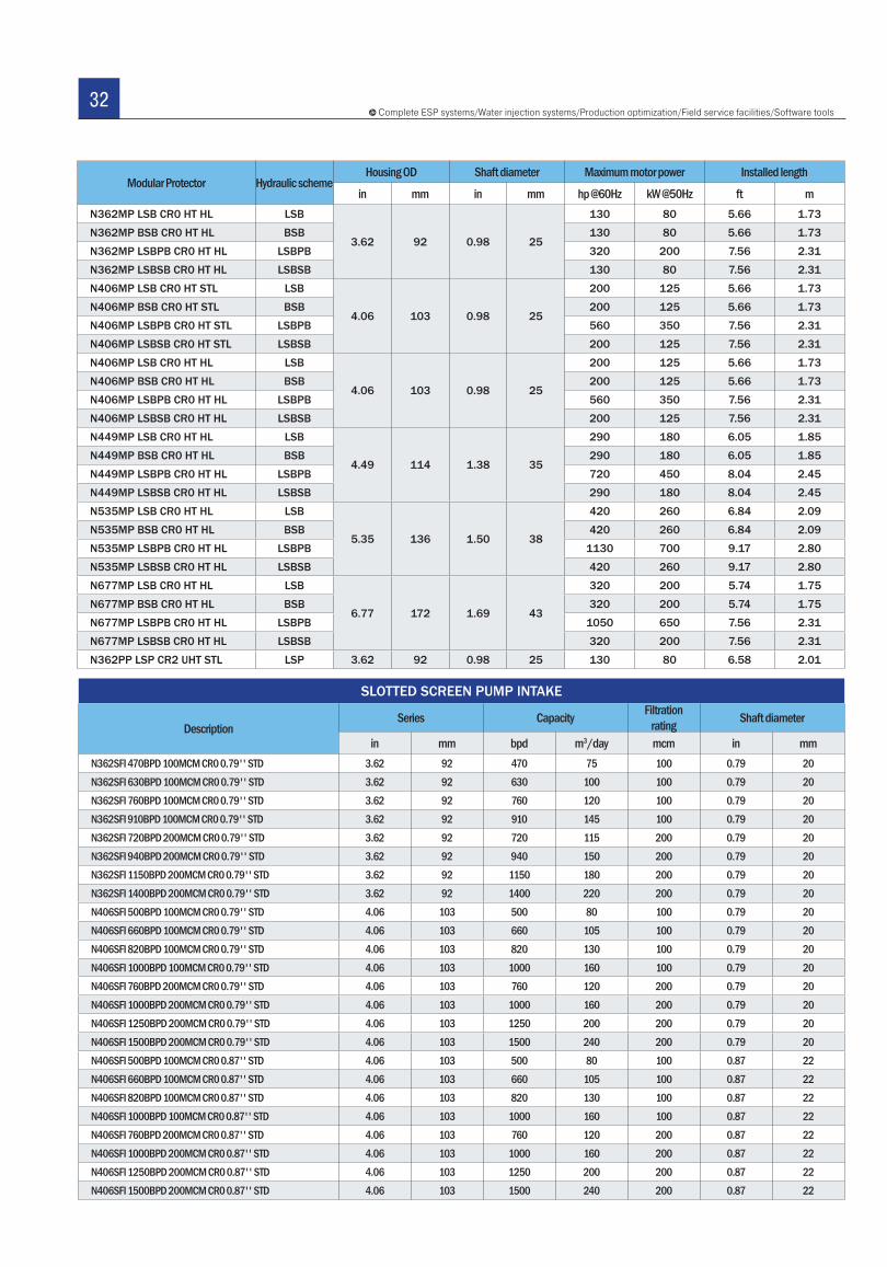
32Complete ESP systems/Water injection systems/Production optimization/Field service facilities/Software tools
SLOTTED SCREEN PUMP INTAKE
Description Series Capacity Filtration
rating Shaft diameter
in mm bpd m3/day mcm in mmN362SFI 470BPD 100MCM CR0 0.79'' STD 3.62 92 470 75 100 0.79 20N362SFI 630BPD 100MCM CR0 0.79'' STD 3.62 92 630 100 100 0.79 20N362SFI 760BPD 100MCM CR0 0.79'' STD 3.62 92 760 120 100 0.79 20N362SFI 910BPD 100MCM CR0 0.79'' STD 3.62 92 910 145 100 0.79 20N362SFI 720BPD 200MCM CR0 0.79'' STD 3.62 92 720 115 200 0.79 20N362SFI 940BPD 200MCM CR0 0.79'' STD 3.62 92 940 150 200 0.79 20N362SFI 1150BPD 200MCM CR0 0.79'' STD 3.62 92 1150 180 200 0.79 20N362SFI 1400BPD 200MCM CR0 0.79'' STD 3.62 92 1400 220 200 0.79 20N406SFI 500BPD 100MCM CR0 0.79'' STD 4.06 103 500 80 100 0.79 20N406SFI 660BPD 100MCM CR0 0.79'' STD 4.06 103 660 105 100 0.79 20N406SFI 820BPD 100MCM CR0 0.79'' STD 4.06 103 820 130 100 0.79 20N406SFI 1000BPD 100MCM CR0 0.79'' STD 4.06 103 1000 160 100 0.79 20N406SFI 760BPD 200MCM CR0 0.79'' STD 4.06 103 760 120 200 0.79 20N406SFI 1000BPD 200MCM CR0 0.79'' STD 4.06 103 1000 160 200 0.79 20N406SFI 1250BPD 200MCM CR0 0.79'' STD 4.06 103 1250 200 200 0.79 20N406SFI 1500BPD 200MCM CR0 0.79'' STD 4.06 103 1500 240 200 0.79 20N406SFI 500BPD 100MCM CR0 0.87'' STD 4.06 103 500 80 100 0.87 22N406SFI 660BPD 100MCM CR0 0.87'' STD 4.06 103 660 105 100 0.87 22N406SFI 820BPD 100MCM CR0 0.87'' STD 4.06 103 820 130 100 0.87 22N406SFI 1000BPD 100MCM CR0 0.87'' STD 4.06 103 1000 160 100 0.87 22N406SFI 760BPD 200MCM CR0 0.87'' STD 4.06 103 760 120 200 0.87 22N406SFI 1000BPD 200MCM CR0 0.87'' STD 4.06 103 1000 160 200 0.87 22N406SFI 1250BPD 200MCM CR0 0.87'' STD 4.06 103 1250 200 200 0.87 22N406SFI 1500BPD 200MCM CR0 0.87'' STD 4.06 103 1500 240 200 0.87 22
Modular Protector Hydraulic schemeHousing OD Shaft diameter Maximum motor power Installed length
in mm in mm hp @60Hz kW @50Hz ft mN362MP LSB CR0 HT HL LSB
3.62 92 0.98 25
130 80 5.66 1.73
N362MP BSB CR0 HT HL BSB 130 80 5.66 1.73
N362MP LSBPB CR0 HT HL LSBPB 320 200 7.56 2.31
N362MP LSBSB CR0 HT HL LSBSB 130 80 7.56 2.31
N406MP LSB CR0 HT STL LSB
4.06 103 0.98 25
200 125 5.66 1.73
N406MP BSB CR0 HT STL BSB 200 125 5.66 1.73
N406MP LSBPB CR0 HT STL LSBPB 560 350 7.56 2.31
N406MP LSBSB CR0 HT STL LSBSB 200 125 7.56 2.31
N406MP LSB CR0 HT HL LSB
4.06 103 0.98 25
200 125 5.66 1.73
N406MP BSB CR0 HT HL BSB 200 125 5.66 1.73
N406MP LSBPB CR0 HT HL LSBPB 560 350 7.56 2.31
N406MP LSBSB CR0 HT HL LSBSB 200 125 7.56 2.31
N449MP LSB CR0 HT HL LSB
4.49 114 1.38 35
290 180 6.05 1.85
N449MP BSB CR0 HT HL BSB 290 180 6.05 1.85
N449MP LSBPB CR0 HT HL LSBPB 720 450 8.04 2.45
N449MP LSBSB CR0 HT HL LSBSB 290 180 8.04 2.45
N535MP LSB CR0 HT HL LSB
5.35 136 1.50 38
420 260 6.84 2.09
N535MP BSB CR0 HT HL BSB 420 260 6.84 2.09
N535MP LSBPB CR0 HT HL LSBPB 1130 700 9.17 2.80
N535MP LSBSB CR0 HT HL LSBSB 420 260 9.17 2.80
N677MP LSB CR0 HT HL LSB
6.77 172 1.69 43
320 200 5.74 1.75
N677MP BSB CR0 HT HL BSB 320 200 5.74 1.75
N677MP LSBPB CR0 HT HL LSBPB 1050 650 7.56 2.31
N677MP LSBSB CR0 HT HL LSBSB 320 200 7.56 2.31
N362РP LSP CR2 UHT STL LSP 3.62 92 0.98 25 130 80 6.58 2.01
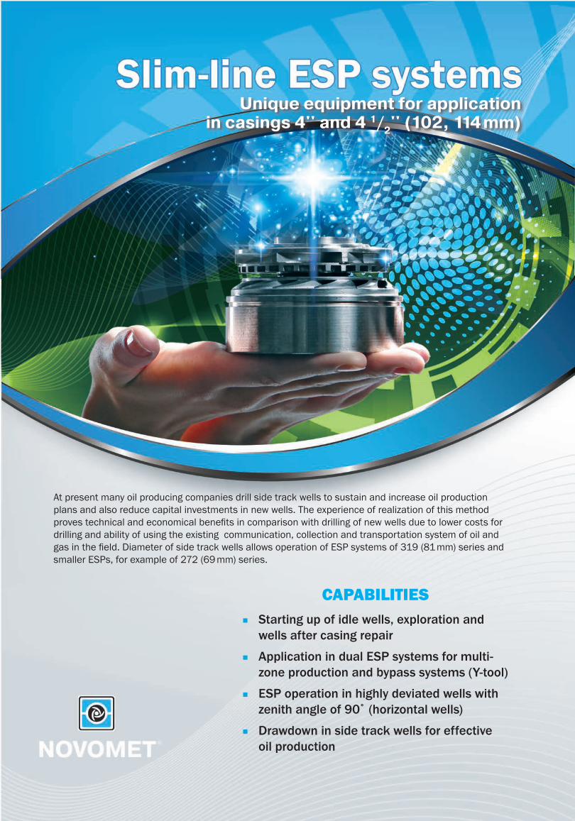
At present many oil producing companies drill side track wells to sustain and increase oil production plans and also reduce capital investments in new wells. The experience of realization of this method proves technical and economical benefi ts in comparison with drilling of new wells due to lower costs for drilling and ability of using the existing communication, collection and transportation system of oil and gas in the fi eld. Diameter of side track wells allows operation of ESP systems of 319 (81 mm) series and smaller ESPs, for example of 272 (69 mm) series.
Unique equipment for applicationin casings 4'' and 4 1/
2'' (102, 114 mm)
CAPABILITIES ■ Starting up of idle wells, exploration and
wells after casing repair ■ Application in dual ESP systems for multi-
zone production and bypass systems (Y-tool) ■ ESP operation in highly deviated wells with
zenith angle of 90˚ (horizontal wells) ■ Drawdown in side track wells for effective
oil production
Headquarters:
395, Shosse Kosmonavtov,Perm, RussiaInternational DepartmentTelephone: +7 342 299 73 44/45Fax: +7 342 296 23 02E-mail: [email protected]/eng
Novomet-Ecuador S.A.
Av. Republica de El Salvador 880 y SueciaEdificio Almirante Colon,Piso 1, Ofc. 21Telephone: 593-2-2252069/70;593-2-2465383Quito, EcuadorE-mail: [email protected]
New Lift Solutions BV Sucursal
Bogota DC, ColombiaTeleport Business ParkCalle 113 # 7 - 21, Torre A Office 501.Telefax: +57 (1) 637 72 58E-mail: [email protected]
Novomet FZE
In charge of MENA region PO Box 72685Office 1004, Executive Heights(DAMAC Bldg.)Tecom Area, DubaiUnited Arab EmiratesTelephone: +971 4 4541469Fax: +971 4 4541468E-mail: [email protected]
Novomet NAP Oilfield Service(Egypt)
Free Zone S.A.ECairo, 39 Road 83 Maadi,Telephone: +202 235 82587Fax: +202 237 87616Mobile: +201 009 602300E-mail: [email protected] facility:Badr City - Industrial Zone,District 3, Block 8
S.C. Novomet Artificial Lift S.R.L.
Bucharest, at district 5,Dr. Herescu Petre street,no. 15, floor 2Telephone:+40 725 388 252E-mail: [email protected]
Novomet-Argentina S.A
the City of Buenos Aireswith domicile at Maipu 1300,13th FloorTelephone: +54 9 297 5923041E-mail: [email protected]
New Lift Solution MexicoS.A. de C.V.
Avenida Concordia No. 23, Piso # 4,Colonia Camaroneros II,Ciudad del Carmen,Estado Campeche, Zip Code 24169Telephone: +52 938 286 0990E-mail: [email protected]
GLOBAL FOOTPRINT
INNOVATE YOUR PRODUCTION WITH NOVOMET!INNOVATE YOUR PRODUCTION WITH NOVOMET!
| 2013