comparative experimental analysis of the e ect caused by
TRANSCRIPT
Comparative experimental analysis of the effect caused by artificial and real induceddamage in composite laminates
Marco A. Péreza,b,∗, Lluís Gila,b, Montserrat Sancheza,b, Sergio Ollerb,c
aLaboratory for the Technological Innovation of Structures and Materials (LITEM), Colon 11, TR45, Terrassa, 08222 Barcelona, SpainbDepartament de Resistència de Materials i Estructures a l’Enginyeria, Universitat Politècnica de Catalunya - BarcelonaTech, Spain
cInternational Center for Numerical Methods in Engineering (CIMNE), Gran Capità s/n, Edifici C1, 08034 Barcelona, Spain
Abstract
This paper presents the results of an extensive experimental campaign aimed to examine the effect upon the vibration response andon the residual load-bearing capacity caused by both: isolated artificially induced interlaminar damage and low-velocity impactinduced damage in composite laminates. The experimental programme included modal testing, drop-weight impact testing, ultra-sonic inspection, transverse quasi-static loading testing and compression testing conducted on a set of 72 carbon fibre-reinforcedcomposite laminated coupons. Both types of damage caused measurable changes in laminate performance, however marked di-vergent trends were observed. The results allowed for conclusions to be drawn regarding the adequacy of the artificial damageapproach and highlighted the importance and role of other forms of degradation upon damage tolerance of laminated compositescontaining damage.
Keywords: Composite laminates, Low-velocity impact, Ultrasonic testing, Experimental modal analysis, Quasi-static loading,Compression after impact
1. Introduction
With the increasing use of composite materials in industrycomes an increasing need of a better understanding of their be-haviour and improving their performance. Over the years, atremendous amount of activity has been devoted to developingaccurate and fast non-destructive evaluation techniques as wellas numerical methodologies, which can quantitatively predictthe performance and durability of composite structures. This isdue to the fact that composite materials represent a departurefrom the way that conventional materials are used, and, con-sequently, they require unconventional approaches to dealingwith them.
During the last decades, a significant research effort has beenparticularly devoted to the study of impact and post-impact be-haviour of laminate composite structures, since this is a phe-nomenon which has greatly hindered their widespread appli-cation. Experimental studies consistently indicate that impactinduced damage is a mixture of three main failure modes: ma-trix cracking, delamination and fibre breakage, among whichdelamination the most severe because it may severely degradethe stiffness and strength of composite structures Reid and Zho(2000); Hodgkinson (2000). Consequently, several studies as-sessed and quantified composite damage resistance and damagetolerance in terms of delaminated area.
Numerous contributions have been made to numericallymodel the damage in composite materials Orifici et al. (2008).
∗Corresponding author.Email address: [email protected] (Marco A. Pérez)
Continuum damage mechanics approaches, which are basedon material degradation models, have proved to be successfulto predict different composite failure modes, including matrixcracking, delamination and fibre breakage Hinton et al. (2004).However, major efforts have been focused on the treatmentof delamination Pagano and Schoeppner (2000): two com-mon approaches are the virtual crack closure technique (VCCT)Krueger (2004) and the cohesive zone models (CZMs) Ca-manho et al. (2003); Lopes et al. (2009). In parallel, numerousexperimental studies dealing with composite damage detectionhave also been published. It is notable that a large number of ex-perimental works were based on the analysis of the influence ofan isolated artificially induced damage Ooijevaar et al. (2010);Wei et al. (2004); Kessler et al. (2002); Yam (2004). It is com-mon practice to induce delamination by inserting a polyimidefilm before consolidating a composite specimen in an autoclave.
As shown, the importance of delamination is well recog-nized. However, for the particular case of an impact, delamina-tion does not occur in isolation. While numerous studies on therelationship between delamination and damage tolerance havebeen reported, little has been found in the literature concern-ing the role of other forms of damage, such as fibre breakageor indentation, in the residual load-bearing capacity. This is-sue could be addressed through numerical modelling. On theother hand, problems can arise when using an experimental ap-proach since different damages are not always accounted forseparately. One approach that may be worthy of considerationis the use an artificially embedded delamination, which allowsthe delamination-type of failure to be decoupled from the otherones.
Preprint submitted to Composite Structures March 15, 2014
Bearing this in mind, the purpose of the present study wasto deeply examine in-depth the effect upon the vibration re-sponse and on the residual load-bearing capacity caused byboth: isolated artificially induced interlaminar damage and low-velocity impact induced damage in composite laminates. Ac-cording to the authors’ knowledge, this topic has not been fullystudied hitherto. This work enters in the continuity of thework conducted by the authors Pérez et al. (2014). This papermainly presents the results of an extensive experimental cam-paign carried out on a set of 72 carbon fibre-reinforced compos-ite laminated coupons. The experimental programme includedmodal testing, drop-weight impact testing, ultrasonic inspec-tion, transverse quasi-static loading testing and compressiontesting. The results showed that both types of damage causedmeasurable changes in composite laminate performance. How-ever, markedly divergent trends between experimental resultsof two types of damage were observed. The results allowed forconclusions to be drawn regarding the adequacy of the artifi-cial approach and highlighted the importance and role of otherforms of damage induced during the impact event.
In the following section, the methodology is described anddetails and requirements of the experimental test procedures aregiven. Subsequently, test results are presented, compared anddiscussed in section three. Finally, the conclusions of the studyare presented.
2. Experimental procedure
The experimental programme involved five main stages:modal testing performed before and after damaging the com-posite laminates, drop-weight impact testing in which dam-age was induced in a controlled manner, ultrasonic inspec-tion which allowed determining the interlaminar damage onsetand the extent of induced delaminations, and finally transversequasi-static loading (QSL) tests and compression after impact(CAI) tests to assess the transverse and compressive residualbearing capacity of composite specimens, respectively.
2.1. Test specimens
The experimental programme was executed for a total of 72monolithic composite plate specimens measuring 150×100×5.2mm3. In the manufacturing process, commercially availableunidirectional prepreg laminae composed of carbon fibres1
(volume-fraction of 55.2 %) embedded in a resin epoxy matrix2
were used. The quasi-isotropic laminated plates were com-posed of 40 unidirectional laminae with a balanced and sym-metric stacking sequence [45◦/0◦/ − 45◦/90◦]5S , resulting in anominal thickness of approximately 5.2 mm with an uniformcross-section over the entire surface. The laminated plate layupwas defined such that the 0◦ fibre orientation was aligned withthe lengthwise dimension. Laminate curing was performed fol-lowing a standard autoclave procedure.
1Grafil TR30S 3K.2Resin epoxy HSC Epikote 4652.
Among the samples manufactured, 48 of them were pristinespecimens while 24 specimens were manufactured by insertingan artificially induced delamination -a circular geometry poly-imide film- before consolidating the coupons in an autoclave.Diameters of 10, 20, 30, 40, 50 or 70 mm were embedded onthe layers 5, 10, 15 or 20 (see Table 1). After the curing pro-cess, pristine coupons were examined using non-destructive ul-trasonic inspection to assess the grade of compaction and todiscard the presence of defects, porosities or delaminations.
2.2. Modal testing
In order to obtain the modal parameters (frequencies andmode shapes) to examine the effect of the induced damage uponthe vibration response, modal testing of the pristine and dam-aged composite laminates was performed. Tests were carriedout under free boundary conditions by suspending the couponsvertically. The real-time sampled signals (excitation and re-sponse) were measured and recorded in form of time seriesand processed into inertance frequency response function (FRF)data. Vibration measurements were performed using a single-reference roving hammer test. A mono-axial accelerometer3
was attached to a single degree of freedom (DoF) referencepoint on the top surface of the laminate, whereas the minia-ture transducer hammer4 roved around, exciting the specimenat 25 measuring DoFs, 5 evenly distributed in the direction ofthe width and 5 evenly distributed in the direction of the length.Because the delamination mode can introduce non-linearitiesAymerich and Staszewski (2010), an effort was made to min-imise them by using mini hammer transducer to create a low-level input excitation. In addition to the transverse modes ofvibration, in-plane modes were also estimated by exciting thespecimen at 5 evenly distributed locations on each lateral side.Both the applied excitation and the measured response5 wereperpendicular to the coupon. Signals were averaged 3 times foreach measurement point, and the test frequency band was up to20 kHz with a resolution of 3.125 Hz.
2.3. Drop-weight impact testing
An ASTM6 D7136 standard test ASTM-D7136 (2007) wasfollowed to determine the damage resistance of the laminatedcomposite specimens subjected to a drop-weight impact event.The test procedure consisted in releasing a weight from a cer-tain height, which determined the incident kinetic energy. Adetailed description of the test conducted can be found in refer-ence Pérez et al. (2013).
A total of 44 coupons were impacted with incident energylevels (EI) ranging from 6.6 to 70 J, in intervals of 5 J, with aminimum of 2 and maximum of 4 specimens tested for each im-pact energy. The lower limit was determined by the minimumheight condition imposed by the standard test method. The up-per limit was defined by considering a hypothetical energy level
3Accelerometer Bruel & Kjaer 4518-003.4Hammer Bruel & Kjaer 8204.5Data acquisition system Bruel & Kjaer 3050-B-6/0.6American Society for Testing and Materials.
2
below both the penetration and perforation thresholds. The 4 re-maining specimens were reserved to ensure the repeatability ofmodal testing and to determine the transverse and compressivebearing capacity of the pristine laminates.
2.4. Ultrasonic testing
The term state of damage implies knowledge of the type, ex-tent and location of induced damage, and it is three-dimensionalin nature. Ultrasonic phased array testing provides a precisethrough thickness damage information useful for determiningthe depth, size and distribution of internal delaminations. Af-ter the drop-weight impact test, the interlaminar damage onsetwas estimated and the extent of induced damage in impactedlaminates coupons was measured by using non-destructive ul-trasonic inspection equipment7. Using data from B and C-scan,depth and extent of the induced delaminations were determinedin terms of projected area. Coupons with artificially embeddeddelamination were also examined to assess the accuracy of theequipment calibration.
2.5. Quasi-static loading testing
The transverse quasi-static loading testing (QSL) may beconsidered as a particular case of low-velocity impact. QSLtest allows determining the transverse stiffness of pristine anddamaged coupons Feraboli and Kedward (2006). The specificstandard test method ASTM D6264 ASTM-D6264 (2007) de-scribes the procedure to carry on measurements of the dam-age resistance of laminated composites to a concentrated quasi-static indentation force, the support fixture. However, the im-pactor as well as the test specimen size were different fromthose outlined in ASTM D7136 ASTM-D7136 (2007) andD7137 ASTM-D7137 (2007). Accordingly, the same supportfixture and procedure ASTM D7136 was followed. The test de-vice consisted of a plate-like fixing support with a rectangularand centered hole cut-out, upon which the sample was placed.The specimen was fixed by four horizontal toggle clamps8.The coupons were perpendicularly loaded9 up to failure witha cross-head displacement rate of 1.25 mm/min. Indentationforce and plate central deflection data were recorded10 at a sam-pling rate of 500 Hz.
QSL tests were performed first on 2 pristine coupons, thenon a series of 12 damaged specimens at various impact energylevels ranging from 6.6 to 70 J, and finally on 12 specimenswith the artificially embedded delamination over the layers 5 or15 (see Table 1).
2.6. Compression after impact testing
The compression after impact (CAI) test determines the com-pressive residual strength of flat rectangular composite platespreviously subjected to an impact event. In the present study,
7OmniScan MX with standard phased array probe 5 MHz linear array 64elements.
8AMF model 6830-3.9250 kN capacity MTS actuator model 244.31.
10Data acquisition system HBM MGCplus.
the same test was employed to determine the residual load-bearing capacity of the specimens manufactured with the ar-tificially embedded delamination. CAI tests were performedusing the support fixture which meets the requirements of thestandard test method ASTM D7137 outlined in ASTM-D7137(2007).
The support fixture was carefully aligned to minimise load-ing eccentricities and specimen induced bending. The couponwas aligned with the lengthwise dimension and loaded with across-head displacement rate of 1.25 mm/min until the maxi-mum load was reached; the load was then reduced to a magni-tude approximately 25% below the maximum. To ensure thatthe applied compressive load did not generate any bending mo-ment on the plates, the strain distribution was monitored duringthe test. Three strain gauge11 pairs were bonded back-to-backon each side of the impacted coupons and one gauge was in-stalled on one side of the coupons with artificially embeddeddelamination. Force, cross-head displacement and strain datawas recorded. A detailed description of the test conducted canbe found in references Pérez et al. (2014, 2012).
CAI tests were performed first on 2 pristine coupons, thenon a series of 32 damaged specimens at various impact energylevels as described above, and finally on 12 specimens with theartificially embedded delamination over the layers 10 or 20 (seeTable 1).
3. Results and discussion
In this section, the results obtained by means of ultrasonicinspection, modal testing, quasi-static loading testing and com-pression after impact testing, of both, impacted and artificiallydamaged laminates, are presented, compared and discussed.
3.1. Ultrasonic inspection
Table 1 collects the characteristics of the manufacturedlaminated specimens with artificially embedded delamination(columns 2 to 4) as well as a summary of the experimental re-sults of ultrasonic inspection (columns 5 to 7). As the extentand depth of the artificial damage were known, this procedureserved to verify the experimental procedure and quantify theerror. In most of the cases, the delaminated area identified pre-sented good agreement with the prediction. Major differencesarose in smaller size defects due to the resolution of the test. Itshould be noticed that some defects were not measured. Thiswas because the length of the probe limited the inspection todefects below 60 mm. On the other hand, the grade of com-paction of the specimens 64/04L6 and 68/08L6 impeded properinspection of these particular laminates. Errors for depth defectestimation were found to be ± 1 layer.
The extent of the internal damage induced by a low-velocityimpact, was determined according to the requirements of thestandard test method ASTM D7136 ASTM-D7136 (2007).
11Strain gauge HBM 1-LY41-6/350.
3
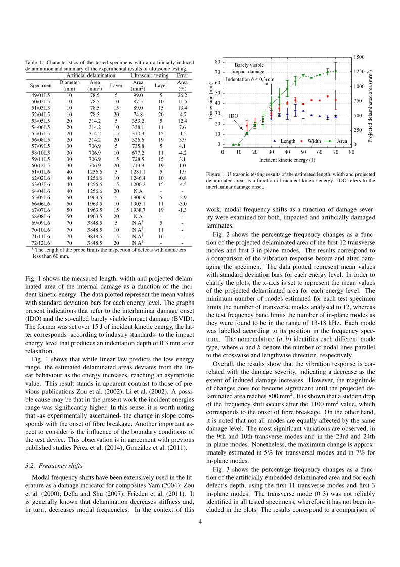
Table 1: Characteristics of the tested specimens with an artificially induceddelamination and summary of the experimental results of ultrasonic testing.
Artificial delamination Ultrasonic testing Error
Specimen Diameter Area Layer Area Layer Area(mm) (mm2) (mm2) (%)
49/01L5 10 78.5 5 99.0 5 26.250/02L5 10 78.5 10 87.5 10 11.551/03L5 10 78.5 15 89.0 15 13.452/04L5 10 78.5 20 74.8 20 -4.753/05L5 20 314.2 5 353.2 5 12.454/06L5 20 314.2 10 338.1 11 7.655/07L5 20 314.2 15 310.3 15 -1.256/08L5 20 314.2 20 326.6 19 3.957/09L5 30 706.9 5 735.8 5 4.158/10L5 30 706.9 10 677.2 11 -4.259/11L5 30 706.9 15 728.5 15 3.160/12L5 30 706.9 20 713.9 19 1.061/01L6 40 1256.6 5 1281.1 5 1.962/02L6 40 1256.6 10 1246.4 10 -0.863/03L6 40 1256.6 15 1200.2 15 -4.564/04L6 40 1256.6 20 N.A - -65/05L6 50 1963.5 5 1906.9 5 -2.966/06L6 50 1963.5 10 1905.1 11 -3.067/07L6 50 1963.5 15 1938.7 19 -1.368/08L6 50 1963.5 20 N.A - -69/09L6 70 3848.5 5 N.A† 5 -70/10L6 70 3848.5 10 N.A† 11 -71/11L6 70 3848.5 15 N.A† 16 -72/12L6 70 3848.5 20 N.A† - -† The length of the probe limits the inspection of defects with diametersless than 60 mm.
Fig. 1 shows the measured length, width and projected delam-inated area of the internal damage as a function of the inci-dent kinetic energy. The data plotted represent the mean valueswith standard deviation bars for each energy level. The graphspresent indications that refer to the interlaminar damage onset(IDO) and the so-called barely visible impact damage (BVID).The former was set over 15 J of incident kinetic energy, the lat-ter corresponds -according to industry standards- to the impactenergy level that produces an indentation depth of 0.3 mm afterrelaxation.
Fig. 1 shows that while linear law predicts the low energyrange, the estimated delaminated areas deviates from the lin-ear behaviour as the energy increases, reaching an asymptoticvalue. This result stands in apparent contrast to those of pre-vious publications Zou et al. (2002); Li et al. (2002). A possi-ble cause may be that in the present work the incident energiesrange was significantly higher. In this sense, it is worth notingthat -as experimentally ascertained- the change in slope corre-sponds with the onset of fibre breakage. Another important as-pect to consider is the influence of the boundary conditions ofthe test device. This observation is in agreement with previouspublished studies Pérez et al. (2014); Gonzàlez et al. (2011).
3.2. Frequency shifts
Modal frequency shifts have been extensively used in the lit-erature as a damage indicator for composites Yam (2004); Zouet al. (2000); Della and Shu (2007); Frieden et al. (2011). Itis generally known that delamination decreases stiffness and,in turn, decreases modal frequencies. In the context of this
Figure 1: Ultrasonic testing results of the estimated length, width and projecteddelaminated area, as a function of incident kinetic energy. IDO refers to theinterlaminar damage onset.
work, modal frequency shifts as a function of damage sever-ity were examined for both, impacted and artificially damagedlaminates.
Fig. 2 shows the percentage frequency changes as a func-tion of the projected delaminated area of the first 12 transversemodes and first 3 in-plane modes. The results correspond toa comparison of the vibration response before and after dam-aging the specimen. The data plotted represent mean valueswith standard deviation bars for each energy level. In order toclarify the plots, the x-axis is set to represent the mean valuesof the projected delaminated area for each energy level. Theminimum number of modes estimated for each test specimenlimits the number of transverse modes analysed to 12, whereasthe test frequency band limits the number of in-plane modes asthey were found to be in the range of 13-18 kHz. Each modewas labelled according to its position in the frequency spec-trum. The nomenclature (a, b) identifies each different modetype, where a and b denote the number of nodal lines parallelto the crosswise and lengthwise direction, respectively.
Overall, the results show that the vibration response is cor-related with the damage severity, indicating a decrease as theextent of induced damage increases. However, the magnitudeof changes does not become significant until the projected de-laminated area reaches 800 mm2. It is shown that a sudden dropof the frequency shift occurs after the 1100 mm2 value, whichcorresponds to the onset of fibre breakage. On the other hand,it is noted that not all modes are equally affected by the samedamage level. The most significant variations are observed, inthe 9th and 10th transverse modes and in the 23rd and 24thin-plane modes. Nonetheless, the maximum change is approx-imately estimated in 5% for transversal modes and in 7% forin-plane modes.
Fig. 3 shows the percentage frequency changes as a func-tion of the artificially embedded delaminated area and for eachdefect’s depth, using the first 11 transverse modes and first 3in-plane modes. The transverse mode (0 3) was not reliablyidentified in all tested specimens, wherefore it has not been in-cluded in the plots. The results correspond to a comparison of
4

Figure 2: Percentage frequency changes as a function of the projected delaminated area of the first 12 transverse modes and first 3 in-plane modes. BVID refers tothe so-called barely visible impact damage.
5

the vibration response of the artificially damaged laminates anda pristine coupon. In general, the frequency shifts show a trendto decrease as the artificial damage size increases. As in theprevious case, it can be observed that the differences are largerfor higher transverse modes. In contrast, the frequencies of thein-plane modes remained almost unchanged within the range ofthe experimental error assumed. These differences can be at-tributed to the effect of fibre breakage, as it will be discussedafterwards.
In order to independently address the study of the influenceof the defect size and the embedded layer, in Fig. 4 the per-centage frequency shifts are represented in a different form, asa function of the artificially embedded delamination depth foreach diameter’s defect. The minimum changes in the in-planemodes and its independence from the damage’s size are againobserved. The most significant variations (with exception of the70 mm delamination) are observed when artificial defects wereembedded over the layers 5 and 20. The former is supposedto be due to resonance cavity created near the surface and thelatter due to the decrease of the transverse stiffness.
In short, while the trend of the results derived from the ar-tificially embedded delaminations proves an influence on thevibration response, hinders the recognition of a conclusive be-haviour pattern.
3.3. Mode shape changesAs has been proved in previous studies, induced delamina-
tions cause irregularities in mode shapes Pérez et al. (2014);Zou et al. (2000); Della and Shu (2007). Thus, by comparingthe similarity between the mode shapes form the damaged andpristine states damage severity can be quantified. In the presentwork, this was addressed firstly by using the Modal AssuranceCriterion (MAC) Allemang (2003), which provides a measureof consistency between two sets of modal vectors, and secondlyby using the PrMAC criterion Pérez et al. (2014), which trans-forms the MAC information into a scalar value. It is defined asfollows:
PrMAC(
dΦ,Φ)
=
m∏i=1
∣∣∣dφti · φi
∣∣∣2dφt
i ·dφiφ
ti · φi
(1)
where dΦ and Φ are the two sets of m modal vectors and dφand φ are estimated from the damaged and pristine states, re-spectively.
The computation of MAC results in a square m−by−m diag-onal matrix, being m the number of modal vectors estimated.Its diagonal values are bounded between zero and one, where avalue of one signifies perfect consistency and a low value indi-cates discordance between the sets of modal vectors. Fig. 5 col-lects the results of the diagonal MAC matrix mean values cor-responding to the transverse modes correlation, as a function ofthe incident kinetic energy (left) and for each coupon with em-bedded delamination (right), respectively. Overall, a decreaseof the correlation coefficients is observed as both damage sizes(real and artificial) increases. It is noted that changes are ofa greater magnitude for the artificially induced damage speci-mens, being more significant on higher modes (as these modes
are associated with local responses), even for the samples withsmaller embedded defects.
Fig. 6 shows the comparison of the results of PrMAC co-efficients corresponding to the first four transverse modes cor-relation, of both, impacted and artificially damaged laminates.Comparison is done in terms of the projected delaminated area.Regarding the impact induced damage results and despite thedispersion, a clear decreasing trend with an increasing amountof damaged area is shown. It is remarkable that in the initialregion -corresponding to the pristine and nearly pristine states-the PrMAC values differ from unity. This result is due to the in-herent experimental error. On the other hand, although curvesfrom artificially damaged laminates exhibit similar trends, de-viations from the former are evident.
Figure 6: Average PrMAC coefficients corresponding to the transverse modescorrelation, as a function of the projected delaminated area of both, impactedand artificially damaged laminates.
As stated in section 3.2 and according to the results exposed,both types of damage have an influence on the vibration re-sponse. Nonetheless, the behaviour clearly diverges, being theartificially embedded delaminations those which cause greaterchanges.
3.4. Transverse load-bearing capacity
The quasi-static loading testing (QSL) allowed the evalua-tion of the transverse stiffness of both, impacted and artificiallydamaged laminates. Following impact tests, 2 pristine and 12impact-damaged coupons were QSL tested to failure. The con-tact force versus midspan deflection curves obtained in QSLtest are shown at Fig. 7. Comparison of the pristine and dam-aged specimens load-displacement curves show that the pristinecoupons suffer two load drops, while impact-damaged couponssuffers only one. The first drop indicates the onset of delamina-tion beyond which the material reloads, while the second cor-responds to the maximum load encountered during QSL test-ing. The initial non-linear stiffness behaviour can be attributedto the contact stresses between the impactor and the specimenand to the indentation created in the specimen surface. Thedecreased gradient of the slope with increasing the amount ofinduced damage is apparent. This is attributed to the induced
6
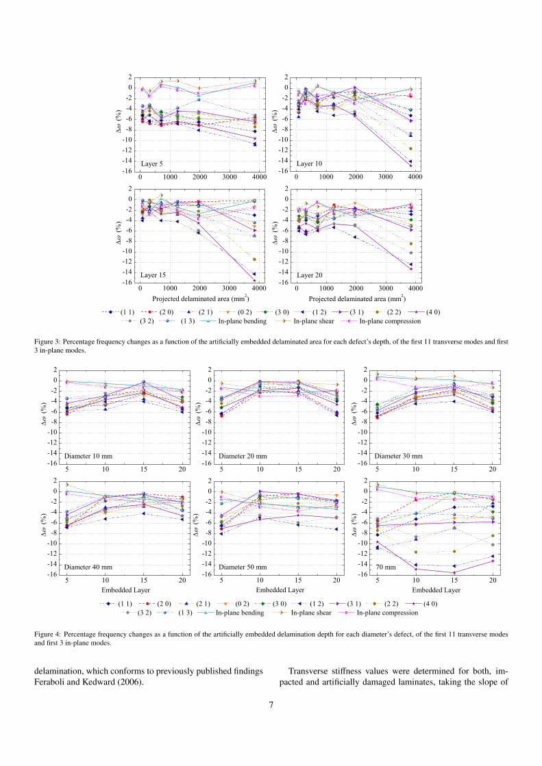
Figure 3: Percentage frequency changes as a function of the artificially embedded delaminated area for each defect’s depth, of the first 11 transverse modes and first3 in-plane modes.
Figure 4: Percentage frequency changes as a function of the artificially embedded delamination depth for each diameter’s defect, of the first 11 transverse modesand first 3 in-plane modes.
delamination, which conforms to previously published findingsFeraboli and Kedward (2006).
Transverse stiffness values were determined for both, im-pacted and artificially damaged laminates, taking the slope of
7
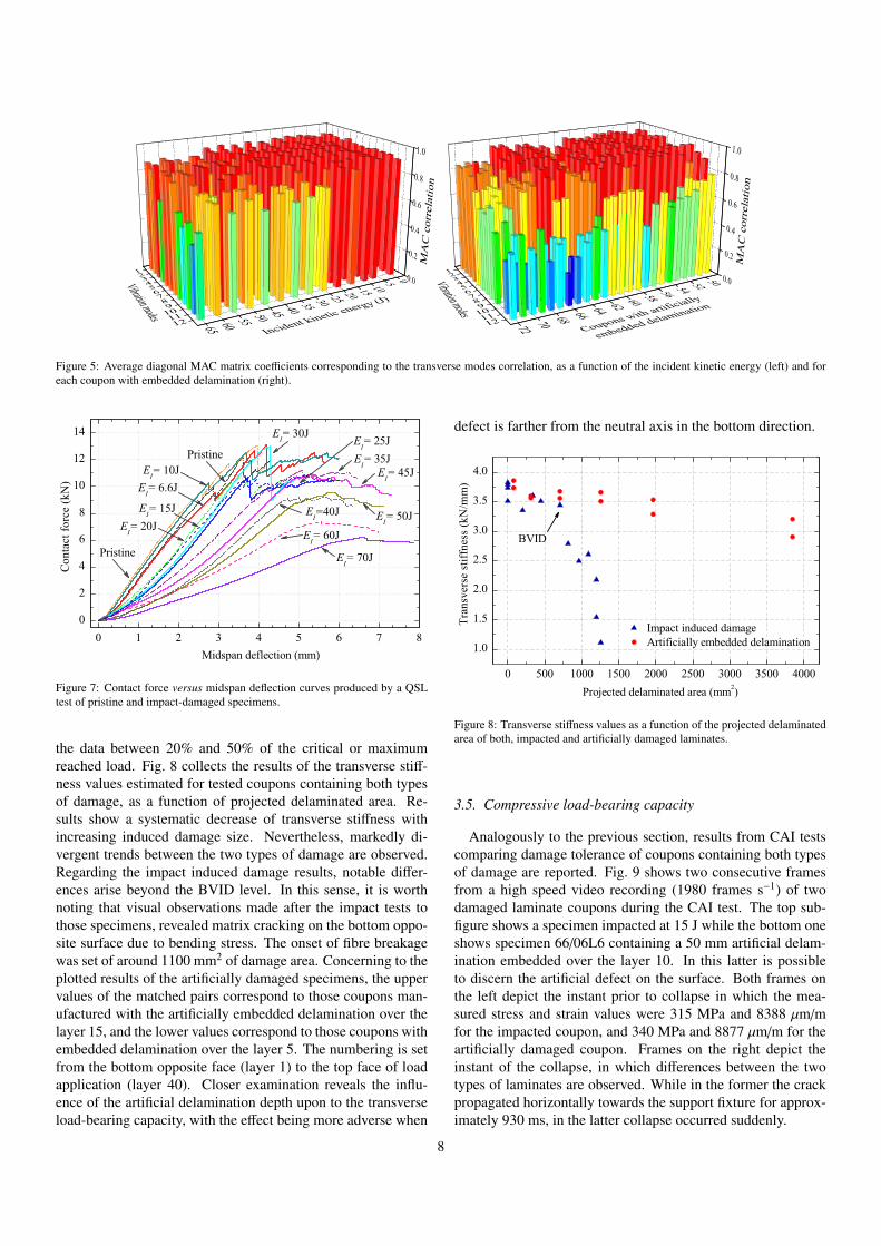
Figure 5: Average diagonal MAC matrix coefficients corresponding to the transverse modes correlation, as a function of the incident kinetic energy (left) and foreach coupon with embedded delamination (right).
Figure 7: Contact force versus midspan deflection curves produced by a QSLtest of pristine and impact-damaged specimens.
the data between 20% and 50% of the critical or maximumreached load. Fig. 8 collects the results of the transverse stiff-ness values estimated for tested coupons containing both typesof damage, as a function of projected delaminated area. Re-sults show a systematic decrease of transverse stiffness withincreasing induced damage size. Nevertheless, markedly di-vergent trends between the two types of damage are observed.Regarding the impact induced damage results, notable differ-ences arise beyond the BVID level. In this sense, it is worthnoting that visual observations made after the impact tests tothose specimens, revealed matrix cracking on the bottom oppo-site surface due to bending stress. The onset of fibre breakagewas set of around 1100 mm2 of damage area. Concerning to theplotted results of the artificially damaged specimens, the uppervalues of the matched pairs correspond to those coupons man-ufactured with the artificially embedded delamination over thelayer 15, and the lower values correspond to those coupons withembedded delamination over the layer 5. The numbering is setfrom the bottom opposite face (layer 1) to the top face of loadapplication (layer 40). Closer examination reveals the influ-ence of the artificial delamination depth upon to the transverseload-bearing capacity, with the effect being more adverse when
defect is farther from the neutral axis in the bottom direction.
Figure 8: Transverse stiffness values as a function of the projected delaminatedarea of both, impacted and artificially damaged laminates.
3.5. Compressive load-bearing capacity
Analogously to the previous section, results from CAI testscomparing damage tolerance of coupons containing both typesof damage are reported. Fig. 9 shows two consecutive framesfrom a high speed video recording (1980 frames s−1) of twodamaged laminate coupons during the CAI test. The top sub-figure shows a specimen impacted at 15 J while the bottom oneshows specimen 66/06L6 containing a 50 mm artificial delam-ination embedded over the layer 10. In this latter is possibleto discern the artificial defect on the surface. Both frames onthe left depict the instant prior to collapse in which the mea-sured stress and strain values were 315 MPa and 8388 µm/mfor the impacted coupon, and 340 MPa and 8877 µm/m for theartificially damaged coupon. Frames on the right depict theinstant of the collapse, in which differences between the twotypes of laminates are observed. While in the former the crackpropagated horizontally towards the support fixture for approx-imately 930 ms, in the latter collapse occurred suddenly.
8
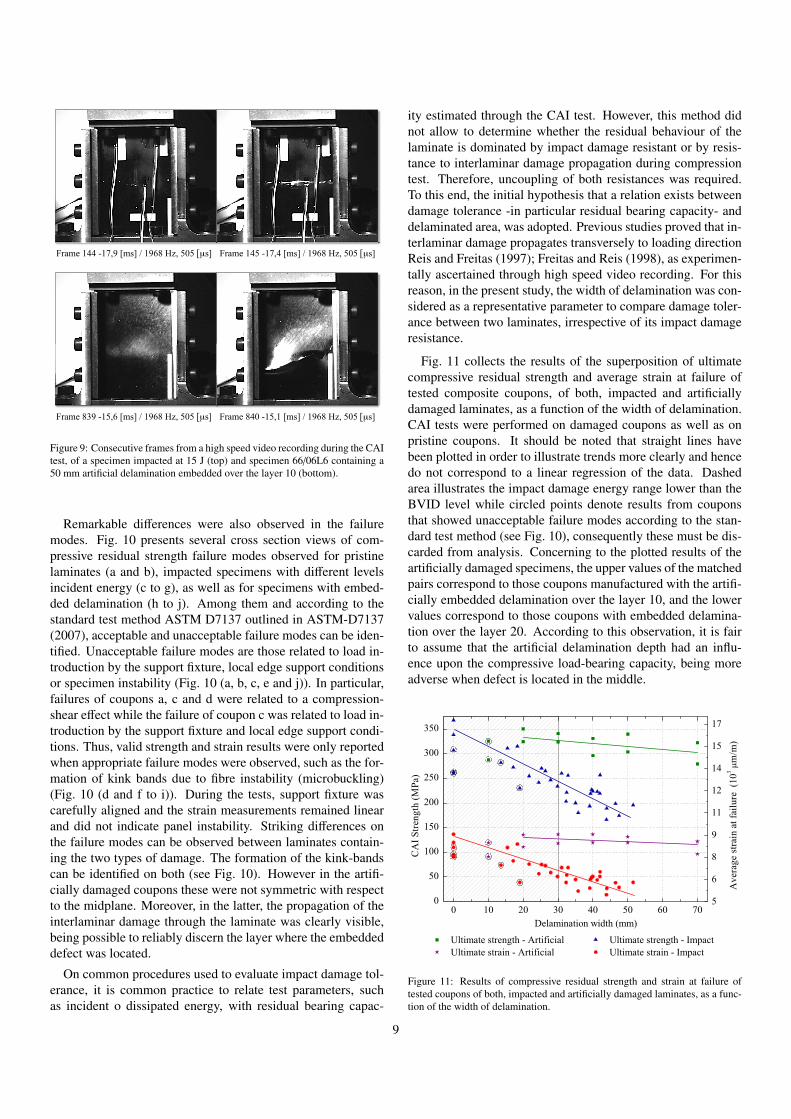
Frame 144 -17,9 [ms] / 1968 Hz, 505 [µs] Frame 145 -17,4 [ms] / 1968 Hz, 505 [µs]
Frame 839 -15,6 [ms] / 1968 Hz, 505 [µs] Frame 840 -15,1 [ms] / 1968 Hz, 505 [µs]
Figure 9: Consecutive frames from a high speed video recording during the CAItest, of a specimen impacted at 15 J (top) and specimen 66/06L6 containing a50 mm artificial delamination embedded over the layer 10 (bottom).
Remarkable differences were also observed in the failuremodes. Fig. 10 presents several cross section views of com-pressive residual strength failure modes observed for pristinelaminates (a and b), impacted specimens with different levelsincident energy (c to g), as well as for specimens with embed-ded delamination (h to j). Among them and according to thestandard test method ASTM D7137 outlined in ASTM-D7137(2007), acceptable and unacceptable failure modes can be iden-tified. Unacceptable failure modes are those related to load in-troduction by the support fixture, local edge support conditionsor specimen instability (Fig. 10 (a, b, c, e and j)). In particular,failures of coupons a, c and d were related to a compression-shear effect while the failure of coupon c was related to load in-troduction by the support fixture and local edge support condi-tions. Thus, valid strength and strain results were only reportedwhen appropriate failure modes were observed, such as the for-mation of kink bands due to fibre instability (microbuckling)(Fig. 10 (d and f to i)). During the tests, support fixture wascarefully aligned and the strain measurements remained linearand did not indicate panel instability. Striking differences onthe failure modes can be observed between laminates contain-ing the two types of damage. The formation of the kink-bandscan be identified on both (see Fig. 10). However in the artifi-cially damaged coupons these were not symmetric with respectto the midplane. Moreover, in the latter, the propagation of theinterlaminar damage through the laminate was clearly visible,being possible to reliably discern the layer where the embeddeddefect was located.
On common procedures used to evaluate impact damage tol-erance, it is common practice to relate test parameters, suchas incident o dissipated energy, with residual bearing capac-
ity estimated through the CAI test. However, this method didnot allow to determine whether the residual behaviour of thelaminate is dominated by impact damage resistant or by resis-tance to interlaminar damage propagation during compressiontest. Therefore, uncoupling of both resistances was required.To this end, the initial hypothesis that a relation exists betweendamage tolerance -in particular residual bearing capacity- anddelaminated area, was adopted. Previous studies proved that in-terlaminar damage propagates transversely to loading directionReis and Freitas (1997); Freitas and Reis (1998), as experimen-tally ascertained through high speed video recording. For thisreason, in the present study, the width of delamination was con-sidered as a representative parameter to compare damage toler-ance between two laminates, irrespective of its impact damageresistance.
Fig. 11 collects the results of the superposition of ultimatecompressive residual strength and average strain at failure oftested composite coupons, of both, impacted and artificiallydamaged laminates, as a function of the width of delamination.CAI tests were performed on damaged coupons as well as onpristine coupons. It should be noted that straight lines havebeen plotted in order to illustrate trends more clearly and hencedo not correspond to a linear regression of the data. Dashedarea illustrates the impact damage energy range lower than theBVID level while circled points denote results from couponsthat showed unacceptable failure modes according to the stan-dard test method (see Fig. 10), consequently these must be dis-carded from analysis. Concerning to the plotted results of theartificially damaged specimens, the upper values of the matchedpairs correspond to those coupons manufactured with the artifi-cially embedded delamination over the layer 10, and the lowervalues correspond to those coupons with embedded delamina-tion over the layer 20. According to this observation, it is fairto assume that the artificial delamination depth had an influ-ence upon the compressive load-bearing capacity, being moreadverse when defect is located in the middle.
Figure 11: Results of compressive residual strength and strain at failure oftested coupons of both, impacted and artificially damaged laminates, as a func-tion of the width of delamination.
9

EI = 15 J
(d)
EI = 25 J
(f)
EI = 65 J
(g)
EI = 20 J
(e)
Pristine
(a)
Pristine
(b)
EI = 6.6 J
(c)
66/06L6/D50E10
(h)
(a) (b) (c) (a) (b) (c) 68/08L6/D50E20
(i)
(a) (b) (c) 72/12L6/D70E20
(j)
Figure 10: Cross section view of compressive residual strength failure modes observed for pristine specimens (a and b), impacted specimens with different levelsincident (EI ) energy (c to g), as well as for specimens with embedded delamination (h to j). a, b, c, e and j coupons showed unacceptable failure modes.
Overall data plotted show a decreasing trend as width of de-lamination increases. Nevertheless, markedly divergent trendsbetween two types of damage are observed, being the impactedcoupons which exhibit a major decrease of its residual com-pressive strength. The present findings suggest that these dif-ferences may be attributed to the fact that only one artificial de-lamination was embedded. Moreover, induced fibre curvatureat the indentation on the impacted face, which proved to havean effect on the initiation of local instability, and fibre breakageare not present on artificially damaged coupons.
4. Conclusions
The results of an extensive experimental campaign conductedon a set of composite laminates coupons containing artificiallyinduced interlaminar damage and low-velocity impact induceddamage were presented and discussed. In order to determinethe effect caused by the presence of both types of damage uponthe vibration response and on the residual load-bearing capac-ity, modal testing, drop-weight impact testing, ultrasonic in-spection, transverse quasi-static loading testing and compres-sion testing have been conducted.
While the availability of a single specimen with unique ar-tificial damage conditions bounds the study, some general andrelative conclusions can be drawn regarding the effect of artifi-cially induced damage. Overall, the results showed that both,the vibration response as well as the residual load-bearing ca-pacity were correlated with the damage severity. Nevertheless,markedly divergent trends between two types of induced dam-age were observed.
From the analysis of the influence of single embedded de-lamination, experimental evidences indicate that delaminationdepth has an influence upon transverse and compressive load-bearing capacity, showing a trend to decrease as the artificialdamage size increases. The effect was more adverse when de-fect was located farther from the neutral axis in the former case(QSL), and when defect was located in the middle in the latter
case (CAI). Regarding the influence on the vibration response,experimental results hinder the recognition of a conclusive be-haviour pattern. When comparing the influence of both typesof damages, experimental results revealed that artificial dam-age caused major changes on the vibration response than thoseinduced by impact damage. In contrast, its influence upon dam-age tolerance proved not be as significant as real impact dam-age.
Finally, fibre breakage showed to have a significant effect onthe vibration response as well as on the transverse stiffness. Onthe other hand, induced fibre curvature at the indentation onthe impacted face, proved to have an effect on the initiation oflocal instability prior to laminate collapse during CAI testing.These findings underline the importance in considering otherforms of damage apart from delamination failure when studyinglaminate structural degradation.
Acknowledgements
This work has been supported by the Spanish Ministry of Sci-ence and Innovation through RECOMP project ref. BIA2005-06952 and DELCOM Project ref. MAT2008-02232/MAT, bythe Spanish Ministry of Public Works (project "Retrofitting andreinforcement of reinforced concrete structures with compositematerials. Numerical and experimental developments appliedto joint of bars and composites anchorage proposal"), by AIR-BUS (Spain) through the Contract No. PBSO-13-06 FEMCOMand ACCIONA Infraestructuras (Spain) through the projectSPHERA. All these support are gratefully acknowledged. Spe-cial thanks also to Roger Serra for useful discussions.
References
S. R. Reid, G. Zho, Impact behaviour of fibre-reinforced composite materialsand structures, CRC Press, 2000.
J. M. Hodgkinson, Mechanical testing of advanced fibre composites, CRCPress, 2000.
10

A. Orifici, I. Herszberg, R. Thomson, Review of methodologies for com-posite material modelling incorporating failure, Compos Struct 86 (2008)194–210. Fourteenth International Conference on Composite Structures(ICCS/14).
M. Hinton, A. Kaddour, P. Soden, Failure criteria in fibre-reinforced-polymercomposites, Elsevier, 2004.
N. Pagano, G. Schoeppner, Delamination of polymer matrix composites: Prob-lems and assessment, in: A. Kelly, C. Zweben (Eds.), Comprehensive Com-posite Materials, Pergamon, Oxford, 2000, pp. 433–528.
R. Krueger, Virtual crack closure technique: history, approach and applications,Appl. Mech. Rev. 57 (2004) 109–143.
P. Camanho, C. Dàvila, M. De Moura, Numerical simulation of mixed-modeprogressive delamination in composite materials, J. Compos. Mater. 37(2003) 1415–1438.
C. Lopes, P. Camanho, Z. Gürdal, P. Maimí, E. Gonzàlez, Low-velocity im-pact damage on dispersed stacking sequence laminates. Part II: Numericalsimulations, Compos Sci Technol 69 (2009) 937–947.
T. Ooijevaar, R. Loendersloot, L. Warnet, A. de Boer, R. Akkerman, Vibrationbased Structural Health Monitoring of a composite T-beam, Compos Struct92 (2010) 2007–2015.
Z. Wei, L. H. Yam, L. Cheng, Detection of internal delamination in multi-layercomposites using wavelet packets combined with modal parameter analysis,Compos Struct 64 (2004) 377–387.
S. S. Kessler, S. M. Spearing, M. J. Atalla, C. E. Cesnik, C. Soutis, Damage de-tection in composite materials using frequency response methods, ComposB Eng 33 (2002) 87–95.
L. H. Yam, Nondestructive Detection of Internal Delamination by Vibration-based Method for Composite Plates, J Compos Mater 38 (2004) 2183–2198.
F. Aymerich, W. J. Staszewski, Impact damage detection in composite lami-nates using nonlinear acoustics, Compos Part A Appl Sci Manuf 41 (2010)1084–1092.
ASTM-D7136, Standard test method for measuring the damage resistance ofa fibre-reinforced polymer matrix composite to a drop-weight impact event,Tech. rep. West Conshohocken (PA, USA): American Society for Testingand Materials (ASTM), 2007.
M. A. Pérez, X. Martínez, S. Oller, L. Gil, F. Rastellini, F. Flores, Impactdamage prediction in carbon fiber-reinforced laminated composite using thematrix-reinforced mixing theory, Compos Struct 104 (2013) 239 – 248.
P. Feraboli, K. T. Kedward, A new composite structure impact performanceassessment program, Compos Sci Technol 66 (2006) 1336–1347.
ASTM-D6264, Standard Test Method for Measuring the Damage Resistanceof a Fiber-Reinforced Polymer-Matrix Composite to a Concentrated Quasi-Static Indentation Force, Tech. rep. West Conshohocken (PA, USA): Amer-ican Society for Testing and Materials (ASTM), 2007.
ASTM-D7137, Standard Test Method for Compressive Residual Strength Prop-erties of Damaged Polymer Matrix Composite Plates, Tech. rep. WestConshohocken (PA, USA): American Society for Testing and Materials(ASTM), 2007.
M. A. Pérez, L. Gil, S. Oller, Impact damage identification in composite lami-nates using vibration testing, Compos Struct 108 (2014) 267 – 276.
M. A. Pérez, L. Gil, S. Oller, Evaluación del daño por impacto en laminados dematerial compuesto mediante la respuesta dinámica (in Spanish), CIMNE,2012.
Z. Zou, S. Reid, S. Li, P. Soden, Application of a delamination model to lami-nated composite structures, Compos Struct 56 (2002) 375–389.
C. Li, N. Hu, J. Cheng, H. Fukunaga, H. Sekine, Low-velocity impact-induceddamage of continuous fiber-reinforced composite laminates. Part II. Veri-fication and numerical investigation, Compos Part A Appl Sci Manuf 33(2002) 1063–1072.
E. Gonzàlez, P. Maimí, P. Camanho, C. Lopes, N. Blanco, Effects of ply cluster-ing in laminated composite plates under low-velocity impact loading, Com-pos Sci Technol 71 (2011) 805–817.
Y. Zou, L. Tong, G. P. Steven, Vibration-Based Model-Dependent Damage (De-lamination) Identification and Health Monitoring for Composite Structures:a Review, J Sound Vib 230 (2000) 357–378.
C. N. Della, D. Shu, Vibration of Delaminated Composite Laminates: A Re-view, Appl Mech Rev 60 (2007) 1–20.
J. Frieden, J. Cugnoni, J. Botsis, T. Gmür, Vibration-based characterizationof impact induced delamination in composite plates using embedded FBGsensors and numerical modelling, Compos B Eng 42 (2011) 607–613.
R. J. Allemang, The modal assurance criterion: twenty years of use and abuse,
Sound and Vibration 37 (2003) 14–23.L. Reis, M. D. Freitas, Damage growth analysis of low velocity impacted com-
posite panels, Composite Structures 38 (1997) 509–515.M. D. Freitas, L. Reis, Failure mechanisms on composite specimens subjected
to compression after impact, Composite Structures 42 (1998) 365–373.
11