compact control unit installation, operation and
TRANSCRIPT

MAN-GPD0009-01 Rev 11 Page 1 of 42
PCS2™
Compact control unit
Installation, Operation and
Maintenance manual
Document Number: MAN-GPD0009-01 Date: 08/11/2016 Revision: 11
Pyroban Ltd,
Endeavour Works
Dolphin Rd, Shoreham-by-Sea
West Sussex
BN43 6QG
United Kingdom
Tel: +44(0) 1273 456800
Copyright Pyroban Ltd; 2016
All rights reserved.

MAN-GPD0009-01 Rev 11 Page 2 of 42
ISSUE DATE NATURE OF CHANGE
01 30/07/12 INITIAL DRAFT FOR COMMENT
02 21/11/12 CORRECT CERT INFO p7
03 21/11/12 CORRECT CERT INFO p6
04 07/03/13 ADD INFO REQUIRED FOR CERTIFICATION
Location of Relay board fuse (lid interior view added)
Current consumption spec updated (60A peak)
Cert numbers for Enclosure with boards added
05 02/04/13 Maintenance check schedule
- Cross reference to lid torque setting added
- Speed sensor output checks aligned to new sensor
Fault finding
- SYSTEM ON/OFF lamp now called SYTEM STATUS
- Power supply checks added
- Cross references updated.
- Note added to reflect system behaviour when System ON/OFF switched to off and engine continues to run
06 10/06/13 Certification marking updated p7.
DIN rail terminals now referenced for Ex i parameters
07 16/12/13 INTIAL RELEASE
08 05/12/14 1. General updates throughout. Page numbering & revision reference in footer changed
2. Page 2 – Full revision history added 3. Section 1. Supply and Specification updated, part numbers
added 4. Section 1.1 Enclosure marking – CE marking added 5. Section 1.2 Function of PCS2 Control unit table expanded 6. Page 11 – Block diagram updated 7. Section 2.1.1 – Lid stops added to the PCS2 figure 8. Section 2.2 – Cable entries details and enclosure variant G
added 9. Section 2.2.1 - Terminals 61/62 description updated and
maximum packing density for LED lamps added 10. Section 2.2.2 – Cable entries details added. PCS2
enclosure internals updated 11. Section 4.1 – Part numbers and lamp picture added 12. Section 6.3.3 – Fuse description and rating updated 13. Section 6.3.4 – Text update 14. Section 8. – PCS2 commissioning procedure updated 15. Section 8.5 – Ambient air temperature updated 16. Section 9. – Terminal schedule updated 17. Section 10. – Telephone number updated 18. Section 11. – References to other manuals updated
09 21/04/15 Section 9. Terminal schedule – terminal 31 to 34 field connection description changed. Reference to V=BAT+/- removed.

MAN-GPD0009-01 Rev 11 Page 3 of 42
10 16/11/15 1. Page 1 - SIRA logo removed 2. Section 2.2 – Reference to enclosure variant G cable
entries removed. Cable glands note updated. 3. Section 2.2.2 – Enclosure variant G removed 4. Section 2.3 – Capacitor value reference updated 5. Section 7 – DIP switch settings table updated 6. Section 9 – Terminals 35 to 38 comments updated 7. Section 9.1 – Terminals 35 to 38 comments updated 8. Section 10 – Pyroban France contact details removed
11 08/11/16 Confidential material statement added in Foreword.
Foreword
The information contained in this manual is confidential and proprietary to Caterpillar. It is intended for circulation only to Caterpillar and Cat dealer employees, or to employees of OEMs intending to purchase and install PCS2 in their equipment.
Distribution of this material must be limited to personnel whose duties require knowledge of such material and is intended exclusively for their information and training. Distribution of this material for other purposes is strictly prohibited without written permission.
Materials and specifications are subject to change without notice. The International System of Units (SI) is used in this publication.
MAN-GPD0009-01 Rev 11 Page 4 of 42
PERSON IN AUTHORITY
Person taking full responsibility for safety procedures and supervision of safety for employees under their control.
SAFETY POINTS
All personnel are expected to use safe practices and to observe all safety requirements and regulations, relevant to the country or locality in which the equipment is being used.
The following safety precautions must be observed, where applicable:
• Do not operate the equipment until you have read and understood the instructions in the “Operating Instructions” sections of this manual.
• Ensure that all operators are adequately trained, have the relevant experience or are under supervision of someone qualified for the job. Pyroban offer servicing and operator training.
• Protection devices must be periodically tested to determine that they are in good operating condition. See maintenance schedule.
OPERATING
Do not attempt to restart equipment if the engine safety systems trips whilst in a hazardous area. Advice from the Person in Authority must be obtained and the cause of the shutdown identified and corrected before re-starting the equipment.

MAN-GPD0009-01 Rev 11 Page 5 of 42
Contents
1. Supply and Specification ............................................................................................... 7
1.1. Enclosure marking ................................................................................................... 8
1.2. Function of PCS2 Control unit .................................................................................. 8
1.3. Shutdown system components ............................................................................... 10
1.4. PCS2 Control unit enclosure description ............................................................... 12 2. Installation .................................................................................................................. 12
2.1. Mechanical installation ........................................................................................... 13 2.1.1. Enclosure dimensions ................................................................................. 13
2.1.2. Mounting enclosure ..................................................................................... 13
2.1.3. Speed sensor installation ............................................................................ 13
2.2. Electrical installation ............................................................................................... 14 2.2.1. Intrinsic safety parameters .......................................................................... 15
2.2.2. Wiring to enclosure ...................................................................................... 18
2.2.3. Closure of enclosure ................................................................................... 19
2.3. Remote indicator LED EMC capacitor .................................................................... 19 3. Operation .................................................................................................................... 20
3.1. Control switches ..................................................................................................... 20 3.1.1. System ON/OFF .......................................................................................... 20
3.1.2. Start ............................................................................................................ 20
3.1.3. Stop ............................................................................................................. 20
4. Test mode ................................................................................................................... 21
4.1. Indicator LEDs ....................................................................................................... 21 4.1.1. Shutdown red LED indicators ...................................................................... 21
4.1.2. System status amber LED indicator ............................................................. 22
4.1.3. Engine running green LED indicator ............................................................ 22
4.2. Recovery from shutdown ........................................................................................ 22
4.3. Recovery from fault ................................................................................................ 22
4.4. Emergency Stop .................................................................................................... 23
4.5. Checking of over speed shutdown function ............................................................ 23
4.6. Shutdown Override facility ...................................................................................... 23
4.7. Calibration of over speed shutdown point ............................................................... 24 5. Maintenance Check Schedule .................................................................................... 25
6. Fault finding ................................................................................................................ 26
6.1. Normal operation.................................................................................................... 26
6.2. Basic checks (enclosure closed) ............................................................................ 26

MAN-GPD0009-01 Rev 11 Page 6 of 42
6.2.1. If remote LED lamps do not illuminate ......................................................... 26
6.2.2. If emergency stop trip indicator is illuminated .............................................. 27
6.2.3. If over temperature trip indicator lamp is illuminated .................................... 27
6.2.4. If Low Oil Pressure trip indicator lamp is flashing ......................................... 27
6.2.5. If SYSTEM ON/OFF indicator is flashing ..................................................... 27
6.3. Further checks (enclosure opened) ........................................................................ 28 6.3.1. Main enclosure view .................................................................................... 28
6.3.2. Lid interior view ........................................................................................... 29
6.3.3. Replaceable fuse ratings ............................................................................. 30
6.3.4. Control board diagnostic indicators .............................................................. 31
6.3.5. Power supply checks ................................................................................... 35
7. DIP SW2 switch settings ............................................................................................. 36
8. PCS2 commissioning procedure ................................................................................. 37
8.1. Insulation resistance test of intrinsically safe system .............................................. 37
8.2. Power up tests with engine not running .................................................................. 37
8.3. Tests with engine running ...................................................................................... 38
8.4. Engine over speed calibration and shutdown check ............................................... 38
8.5. Maximum temperature checks ............................................................................... 39 9. Terminal schedule ...................................................................................................... 40
9.1. Wiring for air start volt free relay output .................................................................. 42 10. Service and support ................................................................................................ 42
11. Reference Manuals ................................................................................................. 42

MAN-GPD0009-01 Rev 11 Page 7 of 42
1. Supply and Specification
PCS2 Standard Component Kit
Pyroban kit P/N 300827722 contains following components:
PCS2 Controller Enclosure P/N 300817034
Speed Sensor P/N 3010007786
Speed Sensor Adaptor P/N 300805386
Speed Sensor Cable (7.5m) P/N 300826609
PCS2 Customer Engine Interface Diagram
Pyroban drawing number 300817036
PCS2 Main control board assembly
Pyroban P/N 300817251/V3.1 firmware version 3.1
Electrical supply
• 12/24V DC nominal
• Absolute rating – Minimum 9V DC Maximum 30V DC
Power consumption (excluding external loads) 20W
Current consumption
• 60A Peak (During solenoid valve actuation)
• 2A Continuous
Ambient temperature range -20 to +60°C
Ingress protection rating IP66 according to IEC 60529
Pressure range 0.8 to 1.1 bar
Weight
70 kg
Speed sensing
Variable reluctance speed sensor with diode clamped output mounted on engine ring
gear. Maximum speed pickup frequency during normal operation to be between 2kHz
and 7kHz. The maximum speed pick up frequency can be calculated as follows -
Maximum speed pick up frequency = (Maximum engine speed in RPM x Teeth on ring
gear) / 60
Over speed electronic response time 250ms max

MAN-GPD0009-01 Rev 11 Page 8 of 42
Switch inputs
Control switch and shutdown switch inputs – volt free, wetting current 6mA
LED outputs
LED drive for Beka Associates type BA390S only
Relay ratings
Board Relay Maximum load
Relay board P/N 300817254 1 to 8 4A at 30VDC
Control board
P/N 300817251/V3.1
Air start 4A at 30VDC
Alternator excitation 4A at 30VDC
Fuel shutdown 2A at 30VDC
Air shutdown 2A at 30VDC
1.1. Enclosure marking
CE marking
IEC/CENELEC marking
Ex d [ib] mb IIB T4
ATEX marking II 2 (2) G
Ambient temperature
-20 to +60 o C Ingress protection IP66
Certification Enclosure Circuit boards Enclosure with circuit boards combined
IECEx IECEx ITS 12.0015U IECEx SIR 12.0037X IECEx ITS 13.0008X
ATEX ITS12ATEX17614U SIRA 12ATEX2099X ITS13ATEX17741X
1.2. Function of PCS2 Control unit
The PCS2 Control unit forms part of a safety shutdown system which is added to a diesel engine to render it safe for use in potentially flammable atmospheres according to BS EN 1834-1-2000 Reciprocating internal combustion engines -Safety requirements for design and construction of engines for use in potentially explosives atmospheres-Part 1: Group II engines for use in flammable gas and vapour atmospheres

MAN-GPD0009-01 Rev 11 Page 9 of 42
The diesel engine is rendered safe by negating the following potential ignition hazards
• Flammable material may be ignited by hot surfaces. The process temperatures (namely exhaust gas temperature after the exhaust gas cooler and coolant temperature) of the engine are limited so that a flammable atmosphere (of gas group IIA or IIB, temperature class T4) will not be ignited. If the engine temperature approaches the limit temperature, the engine is disabled by shutting off the fuel supply. The trip temperature is determined by the choice of over temperature shutdown switch, which is selected in accordance with the required T rating of the equipment. The engine coolant water temperature and the exhaust gas temperature are monitored.
• If the oil supply to the engine fails, mechanical damage or over heating may result, creating a potential ignition hazard. If the oil pressure falls below the oil pressure switch trip level, while the engine is running, the engine is disabled by shutting off the fuel supply.
• Diesel engines may over-speed if flammable material is ingested into the air intake system. This can result in mechanical damage which may ignite a surrounding flammable atmosphere. The maximum engine speed is limited to just above the normal maximum speed of the engine to prevent over speeding. If an over-speed condition is detected, the engine is disabled by shutting off the fuel supply and also the air supply.
• Up to two emergency stops may be provided so that the engine may be brought to a stop by an operator in the event of an emergency. In this event the engine is disabled by shutting off the fuel supply and air supply.
Hazard Fuel supply removed Air supply removed
Exhaust hot surface due to process temperature
✓ Delayed
Hot surface due to coolant process temperature
✓ Delayed
Low oil pressure ✓ Delayed
Over speed ✓ ✓
Emergency stop activated ✓ ✓

MAN-GPD0009-01 Rev 11 Page 10 of 42
1.3. Shutdown system components
A typical system is comprised of the following main components (See diagram below).
• PCS2 Control unit (flameproof Ex d)
• LED indicator panel (intrinsically safe Ex i)
• Control switches (intrinsically safe Ex i)
• Emergency stop switches (flameproof Ex d )
• Water temperature sensor (intrinsically safe Ex i)
• Exhaust temperature sensor (intrinsically safe Ex i)
• Oil pressure sensor (intrinsically safe Ex i)
• Speed sensor (intrinsically safe Ex i)
• Air shutdown valve (refer to H-Valve manual )
• Fuel shutdown valve (application specific )

MAN-GPD0009-01 Rev 11 Page 11 of 42
TEST
MODE
LED
FUEL VALVE OR ENGINE ECU
AIR SHUT OFF VALVE
ENGINE
OIL PRESSURE
PCS2 CONTROL UNIT
CAL OK
LED
CONTROL SWITCHES
STOP
START
SYSTEM ON/OFF
TEST
MODE
SWITCH
CAL
SWITCH
CAL
LED
EMERGENCY STOP (2)
CONTROL SWITCHES
OVERRIDE
SWITCH
INDICATOR LEDS
EXHAUST TEMP
WATER TEMP
ENGINE SPEED

MAN-GPD0009-01 Rev 11 Page 12 of 42
1.4. PCS2 Control unit enclosure description
The PCS2 Control unit comprises of flameproof enclosure housing and electrical and electronic equipment including intrinsically safe associated apparatus.
Control switches and indicator LEDs are mounted on the front of the enclosure.
The enclosure is robust and corrosion resistant. It is manufactured
from Aluminium 6082 T6 which is painted with red polyester paint
to enhance its stain, abrasion and chemical resistance in an
offshore environment. The enclosure has an ingress protection rating of IP66.
2. Installation
Installation must be performed in accordance with EN 60079-14 Electrical installations design, selection and erection. Parts of the PCS2 system employing intrinsic safety protection concepts must be installed in accordance with EN 60079-25 intrinsically safe electrical systems.
Recommended installation practice
• Use crimped ferrules on all wire core terminations
• Mark all wire core terminations with identification corresponding with terminal number in enclosures.
• Use cable trays to support cable runs.
• Earth bond enclosures to chassis as per drawing.
• Electrical installation to be carried out by Compex trained personnel.

MAN-GPD0009-01 Rev 11 Page 13 of 42
2.1. Mechanical installation
2.1.1. Enclosure dimensions
All dimensions are in mm unless otherwise stated. Overall Dimensions
2.1.2. Mounting enclosure
The enclosure must be mounted to a secure base or bracket via the four mounting lugs provided using M10 anti-vibration fixings. The enclosure must be mounted upright with the hinge on the left side. Care should be taken in choosing a mounting location that avoids mechanical damage to the front panel controls and indicators both in normal operation and when the door is opened.
2.1.3. Speed sensor installation
The engine must be disabled during speed sensor installation or adjustment.
The speed sensor must be securely mounted radially to the ring gear so that the teeth of the ring gear run past in close proximity.
Locate a suitable tapped hole in the bell housing. Do not use a drain hole on the bottom of the bell housing. If necessary drill and tap a 5/8” UNF hole in the bell housing in line with the flywheel teeth ensuring that no foreign objects enter the engine. If an adapter is used screw this into the housing.
Apply lubricant to the speed sensor thread to aid future maintenance.

MAN-GPD0009-01 Rev 11 Page 14 of 42
Adjustment procedure:
1. Rotate the flywheel until a tooth tip is visible in the centre of the speed sensor hole. Gently screw in the speed sensor until it just touches the surface.
2. Back out the speed sensor 1 turn.
3. Tighten the locking nut to secure the sensor ensuring that speed sensor position does not change.
4. Connect the speed sensor lead to the speed sensor ready for wiring to the PCS2 Controller.
2.2. Electrical installation
The enclosure must be electrically bonded to the surrounding metalwork on which it is mounted using wire with a minimum cross-sectional area of 6 mm2. Connection into the enclosure is to be made through suitable cable glands. The enclosure contains 12 x M20 cable gland entries and 6 x M25 cable gland entries. See page 18 for cable gland entry arrangement. Glands shall maintain the IP66 rating of the enclosure when installed. Use only suitably certified cable glands. Ensure that cable glands are suitably certified and rated to maintain the IP rating of the enclosure. Certified stopping plugs are to be fitted to unused gland entries.
Only use glands suitable for cable size. Cables leading to the enclosure should be clamped to prevent twisting or pulling. Unused cable entries must be blanked using suitably certified stopping plugs. The enclosure is always supplied with contents fitted. The layouts of these parts are defined under certification documents. The components and their layout must not be modified. The enclosure must be de-energised before opening unless the area is known to be non-hazardous. The flameproof enclosure external earth connection must be connected to earth using a minimum 6mm2 equipotential bonding conductor.
Unused cable cores should be terminated to earth by connection to spare earth DIN terminals or the internal ground stud.

MAN-GPD0009-01 Rev 11 Page 15 of 42
2.2.1. Intrinsic safety parameters
MAXIMUM INPUT VOLTAGE
Um the maximum input voltage for the system is defined as 250V for intrinsic safety purposes to take account of alternator failure. In normal operation the supply is 12/24V dc.
SWITCH INPUTS
Controller DIN rail terminal number pairs Intrinsic safety parameters (each pair)
• 61/62 (Exhaust over temperature switch)
• 63/64 (Water over temperature switch)
• 65/66 (Oil pressure switch)
• 67/68 (Fuel stop)
• 71/72 (Engine start)
• 73/74 (Air valve position switch)
• 75/76 (ON/OFF)
Uo (V) = 5.9
Io (mA) = 18.9
Po (mW) = 28
Co (µF) = 1000
Lo (mH) = 399.1

MAN-GPD0009-01 Rev 11 Page 16 of 42
LED OUTPUTS
Controller DIN rail terminal number pairs Intrinsic safety parameters (each pair)
• 80/81 (Water over temerpature shutdown)
• 82/83 (Exhaust over temperature shutdown)
• 84/85 (Engine over speed shutdown)
• 86/87 (Low oil pressure shutdown)
• 88/89 (Emergency stop 1)
• 90/91 (Emergency stop 2)
• 92/93 (System status)
• 94/95 (Engine running)
• 96/97 (Override active)
Uo (V) = 15.75
Io (mA) = 53.1
Po (mW) = 209
Co (µF) = 2.88
Lo (mH) = 48.5
MAXIMUM PACKING DENSITY FOR LED LAMP PANEL INSTALLATION

MAN-GPD0009-01 Rev 11 Page 17 of 42
SPEED SENSOR INPUT
Controller DIN rail terminal number pair Intrinsic safety parameters
• 77/78 (Engine speed sensor)
Uo (V) = 15.42
Io (mA) = 1.63
Po (mW) = 3.13
Co (µF) = 0.05
Lo (mH) = 53500
Ui(V) = 100
Ii (mA) = 5.06

MAN-GPD0009-01 Rev 11 Page 18 of 42
2.2.2. Wiring to enclosure
Non-intrinsically safe wiring is segregated from intrinsically safe wiring by a terminal separator which must not be removed. When wiring to the enclosure ensure segregation between intrinsically safe and non-intrinsically safe wiring on either side of the terminal separator. Secure conductors so that if they become disconnected from their terminals they will not impinge on other circuits.
Terminal separator between intrinsically safe and non-intrinsically safe
terminals
Intrinsically safe terminals
Non – intrinsically safe terminals
Enclosure cable entries
Bottom view

MAN-GPD0009-01 Rev 11 Page 19 of 42
2.2.3. Closure of enclosure
The enclosure lid must be closed and all lid fixings fitted and tightened to a torque of 28 Nm before operation in a hazardous area. Only use lid fixing screws to the original specification.
M8 x 30mm cap head screws (A4 STAINLESS BS EN ISO 4762)
Ensure that the lid o-ring is not damaged and is correctly fitted in its groove to maintain the IP rating. The unpainted surfaces of the enclosure flange may be coated with grease or Vaseline to prevent corrosion. Ensure that the flanges do not become contaminated with debris.
2.3. Remote indicator LED EMC capacitor
The remote LED indicators must be fitted with a 10nF 10% X7R ceramic capacitor as shown below to prevent spurious partial illumination of the LEDs under some conditions.
MAN-GPD0009-01 Rev 11 Page 20 of 42
3. Operation
3.1. Control switches
Routine operation of the system is performed via the Control switches.
3.1.1. System ON/OFF
When switched to ON the following sequence occurs
• All indicator lamps are illuminated momentarily to allow a check to be made that they are functioning correctly.
• The system runs through self-checking routines and also checks that there are no engine shutdown inputs active. If all checks are passed the PCS2 system then enables the engine by opening the fuel and air shutdown valves.
In normal running (not in Override) if a fault or trip condition occurs the engine will be brought to a stop. In Override running if a fault or trip occurs the engine will continue to run. In either case the fault or trip will be indicated on the remote LEDs.
The fault or trip condition is latched but may be cleared by switching the System ON/OFF switch to the OFF position. The fault or trip will only be cleared once the engine has stopped so if running in Override wait for the engine to come to a stop and for the fault or trip to clear before switching the System ON/OFF switch back to the ON position.
If the fault or trip is still present when switching back to the ON position the system will immediately show the fault or trip condition again. In the case of an over temperature condition it may be necessary to wait until the over temperature condition has been cleared to restart the system. In the case of a fault condition refer to Fault finding Section 6.
3.1.2. Start
The Start button energises a solenoid, (application specific), installed in the starting system circuit which in turn engages with an hydraulic / pneumatic starter motor to crank the engine to bring it into operation.
The system can also be configured to provide a volt free contact to interface with an electric starting system.
3.1.3. Stop
If the engine is running the stop switch removes the fuel supply from the engine to bring it to a stop. Fuel is removed either via an ECU input or via an external solenoid valve.
It is not necessary to hold the Stop button on, once operated it can be released.

MAN-GPD0009-01 Rev 11 Page 21 of 42
The stop switch toggles the fuel supply to the engine off to bring it to a stop. Once stopped the fuel supply is reinstated so that the engine may be started again. Note that if the engine fails to stop within 10 seconds a fault is generated and the air valve is also closed.
4. Test mode
Test mode is used to test the over speed shutdown function. The Test mode LED is illuminated when in Test mode. For normal operation the Test mode switch should be off.
4.1. Indicator LEDs
PCS2 Control unit is designed to operate with Beka red, amber and green BA390S intrinsically safe LED lamps. Each LED lamp requires 10nF capacitor to be fitted. Pyroban can provide LED lamp kit P/N 3010008063 or PCS2 panel with LED kit P/N 300825923.
4.1.1. Shutdown red LED indicators
Illumination of the following LEDs indicates that the corresponding shutdown has occurred
• Water temperature
• Exhaust temperature
• Over speed
• Low oil pressure
• Emergency stop 1
• Emergency stop 2

MAN-GPD0009-01 Rev 11 Page 22 of 42
4.1.2. System status amber LED indicator
The System status indicator is on solid if there are no faults present and flashes if there is a system fault present. If a fault is present then further diagnostics are available from LED indicators within the PCS2 Control unit.
System status indicator System status
On System OK
Flashing Fault present
4.1.3. Engine running green LED indicator
The engine running indicator is illuminated as below
Engine running indicator Engine status
Off Engine stopped
Flashing Engine running
On Engine speed close to calibrated over speed trip point
If the engine is run at maximum speed the Engine running indicator should be on solid. This indicates that the engine is close to the over speed trip point and gives confidence that the engine over speed trip point is calibrated correctly. If the Engine running LED is not on solid when the engine is run at maximum speed the engine over speed trip point should be recalibrated.
4.2. Recovery from shutdown
If the PCS2 system has shut the engine down the cause of the shutdown will be indicated on the indicator LEDs. Note the cause of shutdown and refer to the Fault finding section for remedial action.
The PCS2 shutdown status may be cleared by returning the System ON/OFF switch to OFF. This may take up to 10 seconds. When remedial action has been completed the system may then be operated as normal.
4.3. Recovery from fault
If the System status indicator shows a system fault (flashing) then the fault status indication may be cleared by returning the System ON/OFF switch to the OFF position.

MAN-GPD0009-01 Rev 11 Page 23 of 42
A further attempt should be made to operate the system by switching the System ON/OFF switch to the ON position.
If the System status indicator again shows that there is a system fault then remedial action should be taken. Refer to the Fault finding section for remedial action.
4.4. Emergency Stop
The engine may be brought to a rapid stop by operation of either of the two emergency stops. Operation of the emergency stop removes both fuel and air supplies. The emergency stop function should not be used for routine stopping of the engine as this may put unnecessary stress on the engine or its load.
4.5. Checking of over speed shutdown function
The over speed shutdown trip point may be temporarily reduced to facilitate checking of the over speed shutdown function by adopting the following procedure. (This assumes that the over speed shutdown point has been calibrated see 4.7 ).
• Switch the System ON/OFF switch to ON
• Switch the Test mode switch on.
• Check that the Test mode LED on the PCS2 Control unit is illuminated following the lamp test.
• Start the engine and run it up to normal maximum speed.
• Check that over speed shutdown occurs
• Switch the Test mode switch to OFF.
Note. The engine will be brought to an abrupt stop. Consideration should be given to disconnecting any driven load from the engine.
4.6. Shutdown Override facility
The system may be put into an Override condition. In Override the air and fuel valves are opened to allow the engine to be run regardless of any self-checking fault or shutdown status. The override condition is set via a switch inside of the PCS2 Control unit and is not accessible to the Operator. System ON/OFF Switch requires to be cycled for the override function to become active.
The override status is indicated via an LED indicator on the remote LED panel.
When in override mode PCS2 will not shut the engine down in the event of over temperature, loss of oil pressure, engine over speed or a fault condition. The Emergency stop inputs are still active in Override mode.
The engine must only be operated in override mode when the area is known to be non-hazardous or appropriate hot work permits are in place.
The controls and indicators otherwise behave as normal.

MAN-GPD0009-01 Rev 11 Page 24 of 42
4.7. Calibration of over speed shutdown point
The over speed shutdown calibration may only be performed when the system is in override. (Refer to 4.6)
Calibration is normally only required when the system is commissioned. It will also be necessary to recalibrate the over speed function in the following circumstances
• Failure of a routine over speed shutdown function test
• If the engine running LED does not illuminate on solid when running at maximum engine speed
• The PCS2 Control unit or the Control board within it are replaced
• The engine, the engine ring gear or its maximum speed are changed
(Changing of the speed sensor does not necessitate recalibration of the over speed trip point.)
The over speed shutdown point is calibrated by running the engine up to normal maximum speed then pressing the CAL button on the PCS2 Control unit to initiate the calibration process.
The CAL button must be pressed for four seconds to arm the calibration function. The CAL LED changes from solid to flashing once the calibration function is armed. The calibration process will occur when the CAL button is released. After a short time (up to 10 seconds) the CAL OK LED will illuminate for 2 seconds if the calibration process has been successful.
If the over speed calibration is not successful check that the frequency of the speed signal is within the specified range from 2kHz to 7kHz on normal maximum speed. If necessary use an oscilloscope to check that there is no noise superimposed on the speed signal.
MAN-GPD0009-01 Rev 11 Page 25 of 42
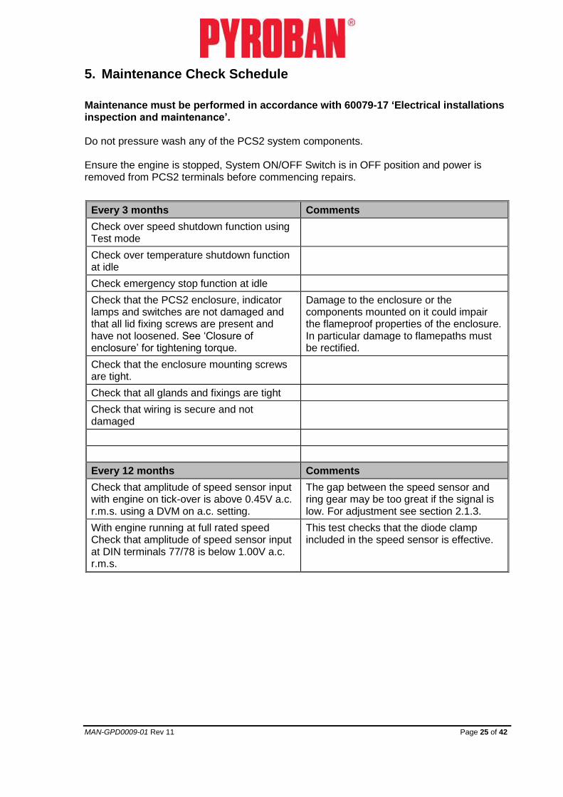
5. Maintenance Check Schedule
Maintenance must be performed in accordance with 60079-17 ‘Electrical installations inspection and maintenance’. Do not pressure wash any of the PCS2 system components. Ensure the engine is stopped, System ON/OFF Switch is in OFF position and power is removed from PCS2 terminals before commencing repairs.
Every 3 months Comments
Check over speed shutdown function using Test mode
Check over temperature shutdown function at idle
Check emergency stop function at idle
Check that the PCS2 enclosure, indicator lamps and switches are not damaged and that all lid fixing screws are present and have not loosened. See ‘Closure of enclosure’ for tightening torque.
Damage to the enclosure or the components mounted on it could impair the flameproof properties of the enclosure. In particular damage to flamepaths must be rectified.
Check that the enclosure mounting screws are tight.
Check that all glands and fixings are tight
Check that wiring is secure and not damaged
Every 12 months Comments
Check that amplitude of speed sensor input with engine on tick-over is above 0.45V a.c. r.m.s. using a DVM on a.c. setting.
The gap between the speed sensor and ring gear may be too great if the signal is low. For adjustment see section 2.1.3.
With engine running at full rated speed Check that amplitude of speed sensor input at DIN terminals 77/78 is below 1.00V a.c. r.m.s.
This test checks that the diode clamp included in the speed sensor is effective.

MAN-GPD0009-01 Rev 11 Page 26 of 42
6. Fault finding
Basic checks should be carried out with the PCS2 Control unit enclosure closed. If the cause of failure cannot be determined with the basic checks then further checks will be needed with the PCS2 Control unit enclosure opened to allow access to the diagnostics lamps. The PCS2 Control unit enclosure may only be opened while the area is known to be non-hazardous.
6.1. Normal operation
Normal operation is as follows when the System ON/OFF Switch is switched from OFF to ON
• Remote LED lamps illuminate momentarily
• All trip indicator remote LEDs are extinguished
o EMERGENCY STOP 1
o EMERGENCY STOP 2
o WATER TEMPERTURE
o EXHAUST TEMPERATURE
• SYSTEM STATUS lamp remains illuminated solid (to indicate normal operation)
• The Air and fuel shutdown valves open to allow the engine to be started
If the system does not behave in this manner then perform the following basic checks.
6.2. Basic checks (enclosure closed)
6.2.1. If remote LED lamps do not illuminate
Upon switching the System ON/OFF Switch to ON, all of the remote LED lamps should illuminate momentarily. If not, then the following potential faults should be investigated
• power to the system could have failed
o Check that the isolator is switched on
o Perform power supply checks (See ‘Power Supply Checks’ section).
• wiring fault on Remote LED indicators
o Check wiring for short circuit and open circuit faults
• wiring fault on the System ON/OFF switch
o Check wiring for short circuit and open circuit faults

MAN-GPD0009-01 Rev 11 Page 27 of 42
If the fault cannot be located perform further checks as section 6.3.
6.2.2. If emergency stop trip indicator is illuminated
• An emergency stop switch may be activated
o Reset emergency stop switches
• wiring fault on emergency stop wiring
o Check wiring for open circuit
6.2.3. If over temperature trip indicator lamp is illuminated
• An over temperature condition may exist
o Allow system to cool and investigate reason for over temperature condition
• wiring fault on temperature switch circuit
o Check wiring for open circuit faults
• Open circuit temperature switch
o When the switch is cool check for continuity through the switch. It should be normally closed.
6.2.4. If Low Oil Pressure trip indicator lamp is flashing
• Open circuit on oil pressure sensor
o Check oil pressure switch continuity
o Check for continuity on oil pressure switch wiring
6.2.5. If SYSTEM ON/OFF indicator is flashing
• The system diagnostics have identified a fault
o Perform further checks as section 6.3

MAN-GPD0009-01 Rev 11 Page 28 of 42
6.3. Further checks (enclosure opened)
6.3.1. Main enclosure view
Control board assembly 300817251 with diagnostic indicators
Remote LED drive board assembly
300817252
Control board input fuses
FUSE 1 and FUSE 4
Non – intrinsically safe terminals
Intrinsically safe terminals
Enclosure fuses
Trunking for intrinsically safe wiring
Trunking for non-intrinsically safe wiring
Control board relay output fuses
FUSE 2 and FUSE 3
FUSE 5 and FUSE 6
(Under Cover Board)
Terminal separator between intrinsically safe and non-intrinsically safe terminals
Control board power supply terminals PL1 1 wrt 2
Override pushbutton
MAN-GPD0009-01 Rev 11 Page 29 of 42
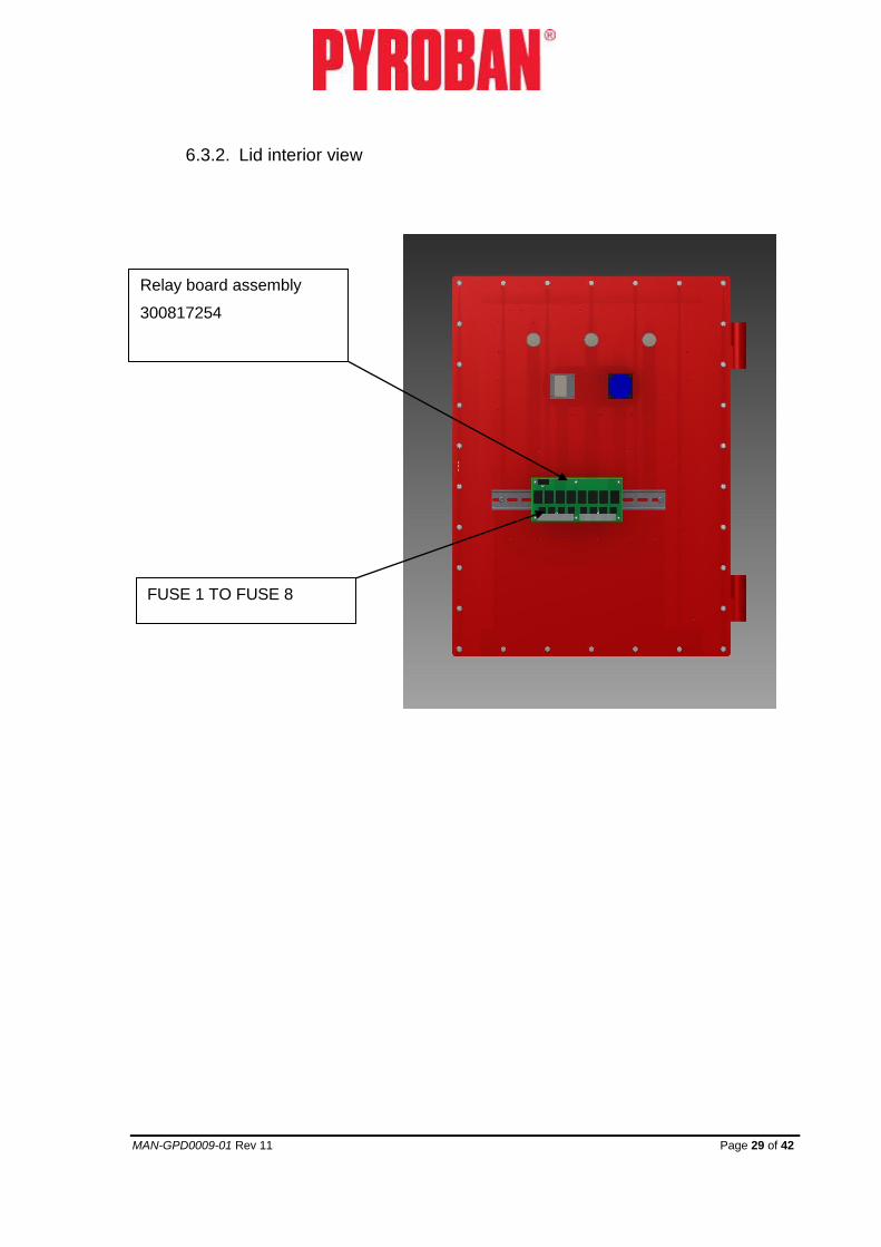
6.3.2. Lid interior view
FUSE 1 TO FUSE 8
Relay board assembly
300817254
MAN-GPD0009-01 Rev 11 Page 30 of 42
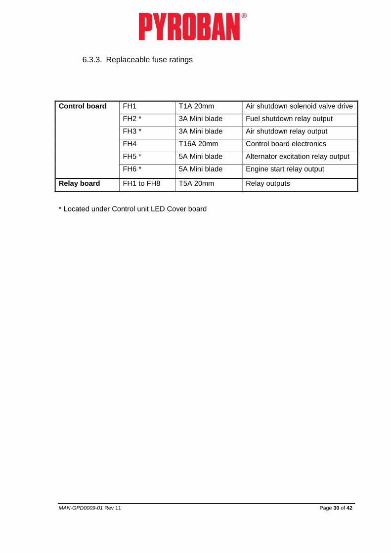
6.3.3. Replaceable fuse ratings
Control board FH1 T1A 20mm Air shutdown solenoid valve drive
FH2 * 3A Mini blade Fuel shutdown relay output
FH3 * 3A Mini blade Air shutdown relay output
FH4 T16A 20mm Control board electronics
FH5 * 5A Mini blade Alternator excitation relay output
FH6 * 5A Mini blade Engine start relay output
Relay board FH1 to FH8 T5A 20mm Relay outputs
* Located under Control unit LED Cover board

MAN-GPD0009-01 Rev 11 Page 31 of 42
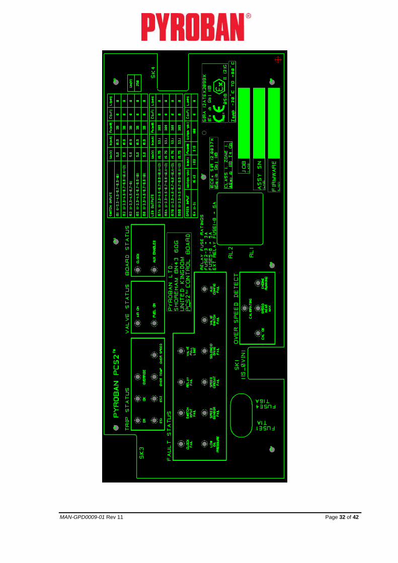
6.3.4. Control board diagnostic indicators
The Control board diagnostic indicators give an indication of current system status. If none of the LEDs is illuminated or flashing, perform power supply checks (See ‘Power Supply Checks’ section 6.3.5). In the event of a diagnostic indicator being illuminated see description below.
In order to clear any present fault, cycle the System ON/OFF switch. After cycling System ON/OFF switch, system will perform start-up diagnostics. Take corrective actions if the fault persists.
Note that returning the System ON/OFF switch to the off position does not become effective until the engine speed signal is no longer present (system requires to be restarted from a known engine condition).
Check sped sensor circuit if engine running signal remains present after the engine has stopped. The engine running signal fault must be rectified before any further diagnostics checks.
MAN-GPD0009-01 Rev 11 Page 32 of 42
MAN-GPD0009-01 Rev 11 Page 33 of 42
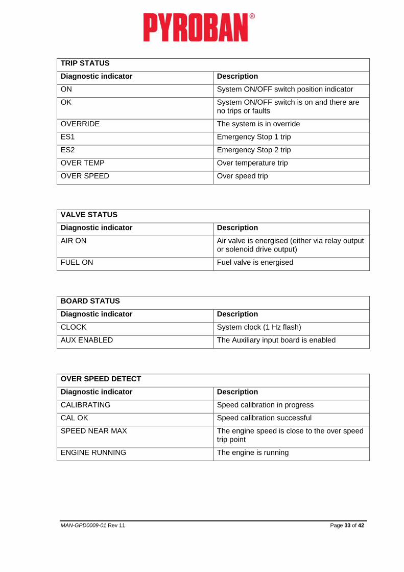
TRIP STATUS
Diagnostic indicator Description
ON System ON/OFF switch position indicator
OK System ON/OFF switch is on and there are no trips or faults
OVERRIDE The system is in override
ES1 Emergency Stop 1 trip
ES2 Emergency Stop 2 trip
OVER TEMP Over temperature trip
OVER SPEED Over speed trip
VALVE STATUS
Diagnostic indicator Description
AIR ON Air valve is energised (either via relay output or solenoid drive output)
FUEL ON Fuel valve is energised
BOARD STATUS
Diagnostic indicator Description
CLOCK System clock (1 Hz flash)
AUX ENABLED The Auxiliary input board is enabled
OVER SPEED DETECT
Diagnostic indicator Description
CALIBRATING Speed calibration in progress
CAL OK Speed calibration successful
SPEED NEAR MAX The engine speed is close to the over speed trip point
ENGINE RUNNING The engine is running

MAN-GPD0009-01 Rev 11 Page 34 of 42
FAULT STATUS
Diagnostic indicator
Description
OK All start up and ongoing diagnostic checks have passed.
CLOCK FAIL System clock failed
Cycle power supply, if fault still exists replace Control board
SWITCH INPUT FAIL
Switch input
Cycle System ON/OFF switch, if fault persists replace Control board
RELAY FAIL Fuel or Air shutdown safety relay failed.
Cycle System ON/OFF switch, if fault persists replace Control board
VALVE PULL LIMIT
The drive to the pull coil of the air valve (if solenoid driven) has exceeded the time limit allowable to prevent overheating.
Cycle System ON/OFF switch, if fault persists replace Control board
LOW OIL PRESSURE
Engine oil pressure has not been detected
Check that oil pressure switch is closed when the engine is running
Check wiring for open circuit faults
SPEED SENSOR FAIL
The engine is running (as determined by presence of oil pressure) but the engine speed signal is not present.
Put system in override mode so that the engine may be run. Check that the signal level from the speed sensor is correct, if not correct check that adjustment of speed sensor is correct. See section 2.1.3.
Check for open circuit or short circuit wiring faults
SPEED CIRCUIT FAIL
The circuit used to receive the engine speed signal has failed
Cycle System ON/OFF switch, if fault persists replace Control board
SOLENOID DRIVE FAIL
The drive circuit for the solenoid operated air valve has failed.
Check that Control board DIP switch settings are correct according to valve type fitted. See section 7
Check connections to air valve.
Check resistance of hold and pull coils is correct.
Cycle System ON/OFF switch, if fault persists replace Control board
VALVE SWITCH FAIL
The air valve switch is indicating that the air valve is stuck open when not energised
Check air valve position. Check wiring for open circuit faults. Check switch operation.

MAN-GPD0009-01 Rev 11 Page 35 of 42
AUX CONFIG FAIL
The diagnostics can detect the presence of the Aux input board and checks that this is consistent with the configuration DIP switch. See section 7.
Check that Aux input board ribbon cable is securely engaged.
VALVE FUSE FAIL
The diagnostics can detect whether Fuse F1 to supply to the valve solenoid drive has failed.
Check Fuse F1 on the Control board
6.3.5. Power supply checks
Check that the voltage at the input terminals to the Control Board PL1 terminals 1 to 2 is between 10.0V and 28V.
If voltage is correct then check F1 on the Control board.
If voltage is not correct then check supply into enclosure on DIN rail terminal 2 and 3. If this is correct check enclosure Fuse F1.

MAN-GPD0009-01 Rev 11 Page 36 of 42
7. DIP SW2 switch settings
The DIP switches SW1 and SW2 on the Control board are used to configure system behaviour as shown in the table below.
The DIP switches can be accessed by temporarily removing the Cover board from the Control board.
DIP SWITCH POSITIONS
U =UP D=DOWN
SW2 SW1
System Configuration
1 2 3 4 1 2
D D D D D D Relay Air Valve without position switch.
U D D D D D Relay Air Valve with position switch.
D U D D D D Solenoid Air Valve without position switch.
U U D D D D Solenoid Air Valve with position switch.
DIP SWITCH SW2 DIP SWITCH SW1

MAN-GPD0009-01 Rev 11 Page 37 of 42
8. PCS2 commissioning procedure
These tests ensure
• Intrinsically safe system is earthed only at one point
• Correct operation of the safety shut-down functions and LED indicators.
• Correct operation of remote LED indicators.
Compliance of the inlet and exhaust system with regard to flameproof enclosures, flame arresters and spark arresters shall be verified. Testing shall be performed only when the area is known to be non-hazardous.
8.1. Insulation resistance test of intrinsically safe system
• Check that PCS2 Controller external earth bonding point is connected to engine chassis via a bonding wire of at least 6mm2
• Disconnect power supply to PCS2 Controller.
• Remove power input connections (Terminals 2 and 3). Fit a temporary link between the power input terminals.
• Perform an insulation resistance check at 500V between the power input terminals and chassis. Check that there is no insulation resistance breakdown for 10 seconds.
• Remove the temporary link between the power input connections and refit the power supply connection observing correct polarity.
8.2. Power up tests with engine not running
Check that the PCS2 Controller is not in override. This can be confirmed by observing the Remote LED indicator marked OVERRIDE. If the PCS2 system is in override the override status can be changed by operating the override pushbutton switch mounted inside of the PCS2 flameproof enclosure. Check that the ENGINE RUNNING LED is not illuminated. With the System ON/OFF switch in the OFF position, switch on power to the PCS2 Controller.
Switch System ON/OFF switch to the ON position and check that all lamps are momentarily illuminated (approximately 1 second) and then all lamps are extinguished apart from the SYSTEM STATUS which should be illuminated solid. If the SYSTEM STATUS lamp is flashing see the fault finding section 6
Check that ECM or Fuel stop solenoid is enabled and air valve enabled.
Open the Water coolant temperature switch circuit and check that ECM or Fuel stop solenoid and air valve are disabled immediately. Check that the Remote LED ‘WATER TEMPERATURE’ is illuminated. Remake the circuit. Reset the system by momentarily returning the System ON/OFF switch to the OFF position. Check that ECM or Fuel stop solenoid is enabled and air valve enabled.
MAN-GPD0009-01 Rev 11 Page 38 of 42
Open the Exhaust temperature switch circuit and check that ECM or Fuel stop solenoid and air valve are disabled immediately. Remake the circuit. Reset the system by momentarily returning the System ON/OFF switch to the OFF position. Check that ECM or Fuel stop solenoid is enabled and air valve enabled.
Activate Emergency Stop 1 and check that ECM or Fuel stop solenoid and air valve are disabled immediately. Reset the Emergency stop switch. Reset the system by momentarily returning the System ON/OFF switch to the OFF position. Check that ECM or Fuel stop solenoid is enabled and air valve enabled.
Activate Emergency Stop 2 and check that ECM or Fuel stop solenoid and air valve are disabled immediately. Reset the Emergency stop switch. Reset the system by momentarily returning the System ON/OFF switch to the OFF position. Check that ECM or Fuel stop solenoid is enabled and air valve enabled.
8.3. Tests with engine running
Run the engine in idle speed. Check that the ENGINE RUNNING LED is flashing. Open the Water coolant temperature switch circuit and check that the engine is immediately brought to a stop. Remake the circuit. Reset the system by momentarily returning the
System ON/OFF switch to the OFF position.
Restart the engine. Open the Exhaust temperature switch circuit and check that the engine is immediately brought to a stop. Remake the circuit. Reset the system by momentarily returning the
System ON/OFF switch to the OFF position.
Restart the engine. Activate Emergency Stop 1 and check that the engine is immediately brought to a stop. Reset the Emergency stop switch. Reset the system by momentarily returning the System ON/OFF switch to the OFF position.
Restart the engine. Activate Emergency Stop 2 and check that the engine is immediately brought to a stop. Reset the Emergency stop switch. Reset the system by momentarily returning the System ON/OFF switch to the OFF position.
8.4. Engine over speed calibration and shutdown check
Put the system into Override via the pushbutton switch mounted inside of the PCS2 flameproof enclosure. With the System ON/OFF switch in the OFF position, switch on power to the PCS2 Controller.
Run the engine at maximum normal speed. Follow section 4.7 for engine speed calibration. Follow the procedure for checking over speed shut-down.

MAN-GPD0009-01 Rev 11 Page 39 of 42
8.5. Maximum temperature checks
With engine running in normal operating conditions determine and record the following data:
• Ambient air temperature (-20ºC to 60ºC)
• Maximum surface temperature reached in operation and after shutdown.
• Maximum engine coolant temperature.
• Maximum exhaust gas temperature measured immediately downstream of the heat exchanger.

MAN-GPD0009-01 Rev 11 Page 40 of 42
9. Terminal schedule
DIN terminal
Field connection Comments
1 MAIN EARTH
2 BATTERY +VE
3 BATTERY -VE
4 ALTERNATOR EXCITATION
5 POWER OUTPUT OPTION
6 POWER OUTPUT OPTION
7 POWER OUTPUT OPTION
8 POWER OUTPUT OPTION
9 EARTH
10 EARTH
11 NO CONNECTION IS GROUND
12 NO CONNECTION IS GROUND
13 NO CONNECTION BATTERY -VE
14 NO CONNECTION BATTERY -VE
15 NO CONNECTION BATTERY -VE
16 NO CONNECTION BATTERY -VE
17/18 EMERGENCY STOP 1 – POLE 1 SENSE
19/20 EMERGENCY STOP 1 – POLE 2 BREAK
21/22 EMERGENCY STOP 2 – POLE 1 SENSE
23/24 EMERGENCY STOP 2 – POLE 2 BREAK
25/26 EARTH
27 AIR SHUTDOWN VALVE (COMMON) +VE V = BAT +VE
28 NO CONNECTION
29 AIR SHUTDOWN VALVE (HOLD COIL) LOW SIDE DRIVE
30 AIR SHUTDOWN VALVE (PULL COIL) LOW SIDE DRIVE
31 AIR SHUTDOWN RELAY +VE
32 AIR SHUTDOWN RELAY –VE
33 FUEL SHUTDOWN RELAY -VE
34 FUEL SHUTDOWN RELAY +VE
35 AIR START RELAY +VE (V=BAT +) JUMPERS
FIT TO 101/102
FIT TO 36/38
36 AIR START RELAY –VE (V=BAT -)
37 DO NOT CONNECT

MAN-GPD0009-01 Rev 11 Page 41 of 42
38 DO NOT CONNECT
39/40 EARTH
41/42 OVERRIDE ON RELAY OUTPUT N/O
43/44 ENGINE RUNNING RELAY OUTPUT N/O
45/46 SYSTEM OK RELAY OUTPUT N/O
47/48 EMERGENCY STOP RELAY OUTPUT N/O
49/50 LOW OIL PRESSURE RELAY OUTPUT N/O
51/52 OVER SPEED TRIP RELAY OUTPUT N/O
53/54 EXHAUST TEMPERATURE TRIP RELAY OUTPUT
N/O
55/56 WATER TEMPERATURE TRIP RELAY OUTPUT
N/O
57/58 EARTH
INTRINSIC SAFETY TERMINAL SEPARATOR
59/60 EARTH
61/62 EXHAUST TEMPERATURE SWITCH INPUT
63/64 WATER TEMPERATURE SWITCH INPUT
65/66 OIL PRESSURE SWITCH INPUT
67/68 FUEL STOP SWITCH INPUT
69/70 EARTH
71/72 ENGINE START SWITCH INPUT
73/74 AIR VALVE POSITION SWITCH INPUT
75/76 ENGINE ON/OFF SWITCH INPUT
77/78 SPEED SENSOR INPUT
79 SPEED SENSOR SCREEN
80 WATER TEMPERATURE LED - OUTPUT
81 WATER TEMPERATURE LED + OUTPUT
82 EXHAUST TEMPERATURE LED - OUTPUT
83 EXHAUST TEMPERATURE LED + OUTPUT
84 OVER SPEED LED - OUTPUT
85 OVER SPEED LED + OUTPUT
86 LOW OIL PRESSURE LED - OUTPUT
87 LOW OIL PRESSURE LED + OUTPUT
88 EMERGENCY STOP 1 LED - OUTPUT
89 EMERGENCY STOP 1 LED + OUTPUT

MAN-GPD0009-01 Rev 11 Page 42 of 42
90 EMERGENCY STOP 2 LED - OUTPUT
91 EMERGENCY STOP 2 LED + OUTPUT
92 SYSTEM STATUS LED - OUTPUT
93 SYSTEM STATUS LED + OUTPUT
94 ENGINE RUNNING / MAXIMUM LED - OUTPUT
95 ENGINE RUNNING / MAXIMUM LED + OUTPUT
96 OVERRIDE LED - OUTPUT
97 OVERRIDE LED + OUTPUT
98/99 EARTH
9.1. Wiring for air start volt free relay output
35 AIR START RELAY VOLT FREE OUTPUT N/O
JUMPERS
FIT TO 102/103
36 AIR START RELAY VOLT FREE OUTPUT COM
37 DO NOT CONNECT
38 DO NOT CONNECT
10. Service and support
Pyroban Limited
Endeavour Works Dolphin Road
Shoreham-by-Sea
Sussex BN43 6QG
United Kingdom
Pyroban Benelux BV
Grotenoord 24-26 - 3341 LT
P.O. Box 229 - 3340 AE
Hendrik Ido Ambacht
Nederland
Telephone: +44 (0) 1273 456800
Email: [email protected]
www.pyroban.com
Telephone: +31 (0) 78 6819377
Fax: +31 (0) 78 6818213
Email: [email protected]
www.pyroban.com
11. Reference Manuals
• Offshore Kits Manual OG003
• SVH Valve Manual