installation, operation and maintenance manual for … · 2016-05-10 · installation, operation...
TRANSCRIPT
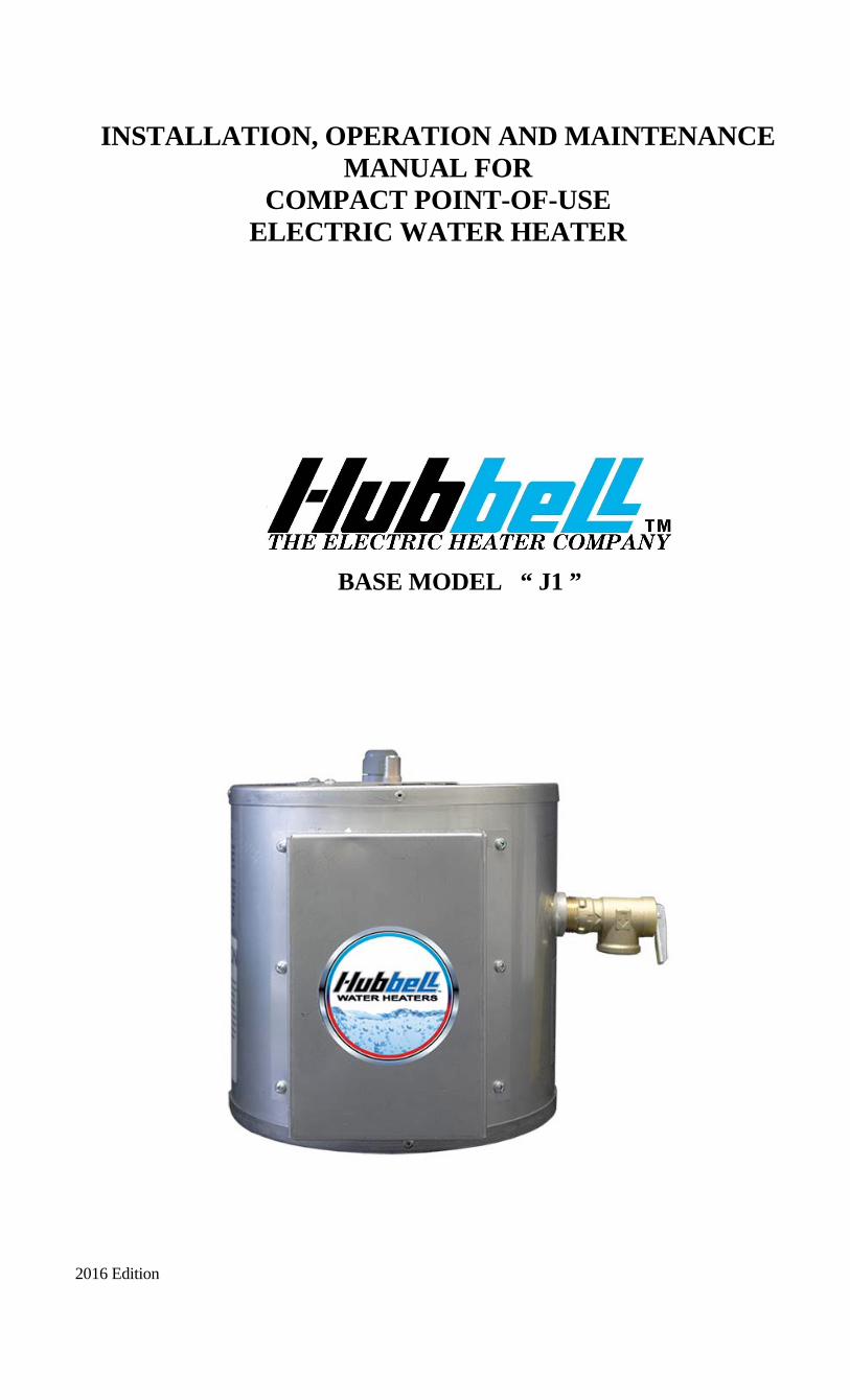
INSTALLATION, OPERATION AND MAINTENANCE MANUAL FOR
COMPACT POINT-OF-USE ELECTRIC WATER HEATER
BASE MODEL “ J1 ”
2016 Edition

2
HUBBELL ELECTRIC HEATER COMPANY
P.O.BOX 288 STRATFORD, CT 06615
PHONE: (203) 378-2659 FAX: (203) 378-3593
INTERNET: http://www.hubbellheaters.com/
-- IMPORTANT -- Always reference the full model number and serial number when calling the factory.
The following information should be noted at time of installation and retained for future reference. Serial No.: Date Installed: Dealer's Name: Address: City and State:
3
WARNING / CAUTION
1. Please read all instructions prior to installing water heater.
2. Tank is to be completely filled with water and all air is to be vented before energizing.
3. Due to the rigors of transportation, all connections should be checked for tightness before heater is placed in operation.
4. Safety relief valve must be installed in tapping provided.
5. The refractory material used in heating elements may absorb some moisture during transit, periods of storage, or when subjected to a humid environment. This moisture absorption results in a cold insulation resistance of less than twenty (20) megohms. If this heater has been subjected to the above condition, each heating element must be checked for insulation resistance before energizing. A low megohm condition can be corrected by removing the terminal hardware and baking the element in an oven at 350°F -700°F for several hours or until the proper megohm reading is obtained.
6. KEEP AWAY FROM LIVE ELECTRICAL CIRCUITS. Do not perform any maintenance, make any adjustments, or replace any components inside the control panel with the high voltage power supply turned on. Under certain circumstances, dangerous potentials may exist even when the power supply is off. To avoid casualties, always turn the power supply safety switch to off, turn the charge or ground the circuit before performing any maintenance or adjustment procedure.
7. This appliance is designed to store water heated only by the electrical elements provided, at temperature of not more than 125°F and pressures of not more than 150 psi. Heat input from any external or additional source will void the warranty.
8. The design anticipates the proper installation and care in use of the product. There is a risk of property damage and personal injury inherent in these of any hot water system. The Company cannot supervise the installation and therefore make it a specific condition of the warranty that the customer will supervise the installation and use of this product to be sure they are performed in accordance with safe guidelines and proper local or national codes. Generalized instructions and procedures cannot anticipate all situations. For this reason, only qualified installers should perform the installations. A qualified installer is a person who has licensed training and a working knowledge of the applicable codes regulation, tools, equipment, and methods necessary for safe installation of an electric resistance water heater. If questions regarding installation arise, check your local plumbing and electrical inspectors for proper procedures and codes. If you cannot obtain the required information, contact the company.
4
TABLE OF CONTENTS
SECTION TITLE PAGE #
I GENERAL INFORMATION 6
II INSTALLATION GUIDELINES 7
III SCHEDULED MAINTENANCE AND OPERATION 12
IV TROUBLESHOOTING 13
V SERVICING AND REPLACEMENT OF PARTS 14
VI WARRANTY 17
5
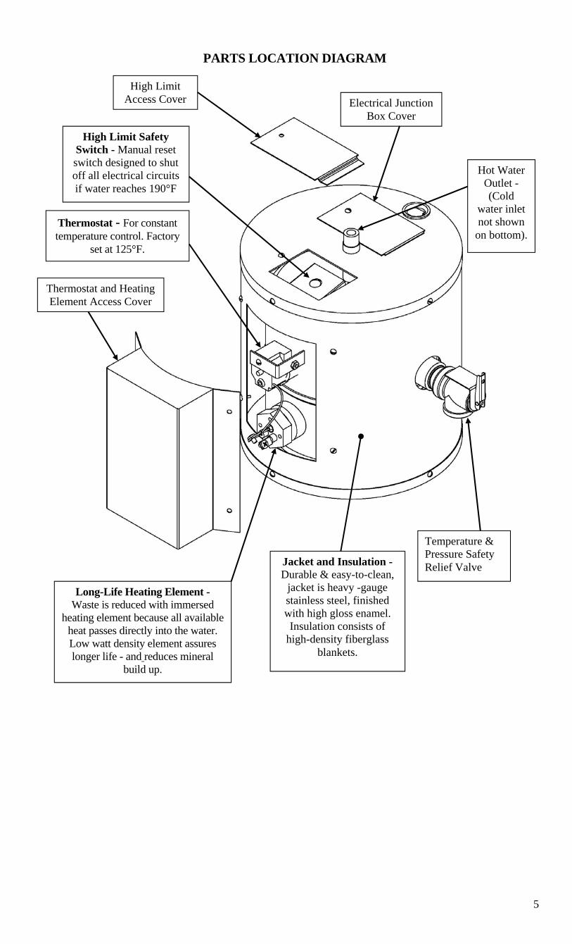
PARTS LOCATION DIAGRAM
High Limit Access Cover Electrical Junction
Box Cover
Hot Water Outlet - (Cold
water inlet not shown
on bottom).
High Limit Safety Switch - Manual reset switch designed to shut off all electrical circuits if water reaches 190°F
Thermostat - For constant temperature control. Factory
set at 125°F.
Thermostat and Heating Element Access Cover
Long-Life Heating Element - Waste is reduced with immersed
heating element because all available heat passes directly into the water. Low watt density element assures longer life - and reduces mineral
build up.
Jacket and Insulation - Durable & easy-to-clean,
jacket is heavy -gauge stainless steel, finished with high gloss enamel. Insulation consists of
high-density fiberglass blankets.
Temperature & Pressure Safety Relief Valve

6
SECTION I - GENERAL INFORMATION
GENERAL DESCRIPTION This book describes a packaged electric water heater that is a stationary, self-contained unit. The complete assembly consists of the storage tank, immersion electric heating element(s), thermostat, safety relief valve, safety high temperature cut out, and any other required electrical operating control. Optional equipment may be supplied with your unit. Please consult the product drawing for details specific to your assembly. The unit is factory assembled, insulated, jacketed, wired, tested, and ready for electrical and plumbing service connections. CONSTRUCTION TANK The one-gallon storage tank is constructed of stainless steel and is designed for a maximum allowable working pressure of 150 psi (300 psi TP). TANK CONNECTIONS The heater is supplied with separate ¼” MNPT cold water and hot water connections. A ¾-inch FNPT connection is located on the side of the heater for mounting a combination safety temperature and pressure relief valve. An overflow line should be utilized from the relief valve outlet to a floor drain. See drawing for locations and sizes. HEATING ELEMENT The water heater is supplied with either a 1000 watt or a 450-watt electric immersion heating element assembly, rated for 120 volts, and composed of a copper sheathed element that is brazed into a 1” NPT brass plug.
TEMPERATURE HIGH LIMIT SWITCH As a safety device, a surface mounted high temperature cut-off switch with manual reset, factory set at 190° F, is provided. In the event of an over-temperature condition, the thermostat will disengage the power from the system. If this switch operates, do not attempt to reset. A dangerous situation is indicated and a qualified service person should be called to find the source before the unit is operated again. Manual Reset CONTROL THERMOSTAT The temperature of the water in the heater is regulated by the adjustable, automatic, immersion thermostat located behind the jacket front cover. This automatic control is set at the factory to maintain a water temperature of 125°F to reduce the risk of scald injury. The thermostat dial is graduated with markings form 1 to 10 with 10 being the hottest.
Capillary Tube and Bulb

7
OUTER SHELL AND INSULATION The tank is encapsulated in 1-inch thick fiberglass insulation. The tank and insulation is protected by a stainless steel protective jacket. THERMOSTATIC MIXING VALVE (Optional) An optional thermostatic mixing valve listed in accordance with ASSE 1017, ASSE 1069, and ASSE 1070 may be supplied to increase the amount of available hot water and limit the hot water temperature to the fixture(s). The ½” NPT valve is adjustable from 80° - 120° F and is typically used when supplying hot water to multiple lavatories from a single unit. WALL BRACKET (Optional) An optional wall bracket is available for easy mounting of the heater.
SECTION II – INSTALLATION GUIDELINES
WARNING / CAUTION DO NOT TURN ON THE ELECTRIC POWER SUPPLY to this equipment until heater is completely filled with water and all air has been released. If the heater is NOT filled with water when the power is turned on, the heating elements will burn out. For protection against excessive pressures and temperatures, local codes require the installation of a temperature-and-pressure (T&P) relief valve certified by a nationally recognized laboratory that maintains periodic inspection of production of listed equipment of materials, as meeting the requirements for Relief Valves and Automatic Gas Shutoff for Hot Water Supply Systems. ANSI Z21.22-1971. A relief valve is designed to discharge excessively hot water. THE CUSTOMER IS RESPONSIBLE TO PROTECT PROPERTY AND PERSONNEL FROM HARM WHEN THE VALVE FUNCTIONS. All water heaters have a risk of leakage at some unpredictable time. IT IS THE CUSTOMER'S RESPONSIBILITY TO PROVIDE A CATCH PAN OR OTHER ADEQUATE MEANS, SO THAT THE RESULTANT FLOW OF WATER WILL NOT DAMAGE FURNISHINGS OR PROPERTY.
The warranty provided assures replacement within its terms, but specifically does not warrant against consequential damage caused by failure to follow these instructions. UNPACKING AND INSPECTING THE HEATER
1. Remove the unit from the shipping carton and visually inspect for any sign of damage. A damaged unit should not be installed, but returned to the factory for replacement.
WATER HEATER PLACEMENT • Locate the heater in a clean, dry location nearest to the point of most frequent hot
water use. • Secure the water heater. Optional wall mounting brackets may be utilized, if supplied. • The water heater should be protected from freezing and waterlines insulated to reduce
energy and water waste. • Leave sufficient room to service the heater. • Do not install in an area where flammable liquids or combustible vapors are present.
8
PIPING INSTALLATION NOTE: The most effective means for preventing deterioration from accelerated corrosion due to galvanic and stray current is the installation of dielectric fittings/unions. The installation of these fittings is the responsibility of the installing contractor.
1. Connect the cold water inlet and hot water outlet to the appropriate connections as shown; refer to installation diagram.
2. Provide a shut off valve in the cold water line. Mark for future emergency use. 3. If pressure reducers or any other restrictions are put in the cold water line, special
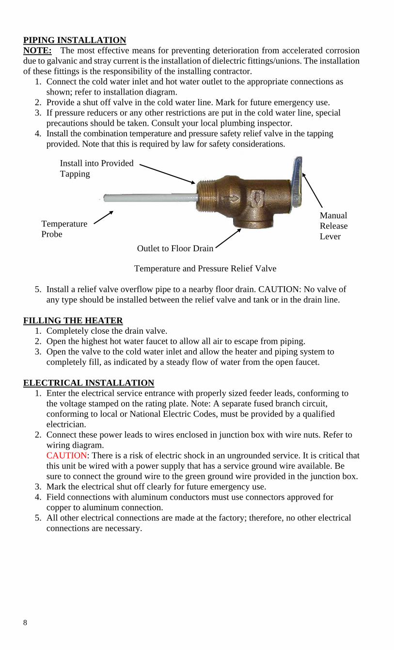
precautions should be taken. Consult your local plumbing inspector. 4. Install the combination temperature and pressure safety relief valve in the tapping
provided. Note that this is required by law for safety considerations.
Temperature and Pressure Relief Valve
5. Install a relief valve overflow pipe to a nearby floor drain. CAUTION: No valve of any type should be installed between the relief valve and tank or in the drain line.
FILLING THE HEATER
1. Completely close the drain valve. 2. Open the highest hot water faucet to allow all air to escape from piping. 3. Open the valve to the cold water inlet and allow the heater and piping system to
completely fill, as indicated by a steady flow of water from the open faucet.
ELECTRICAL INSTALLATION 1. Enter the electrical service entrance with properly sized feeder leads, conforming to
the voltage stamped on the rating plate. Note: A separate fused branch circuit, conforming to local or National Electric Codes, must be provided by a qualified electrician.
2. Connect these power leads to wires enclosed in junction box with wire nuts. Refer to wiring diagram. CAUTION: There is a risk of electric shock in an ungrounded service. It is critical that this unit be wired with a power supply that has a service ground wire available. Be sure to connect the ground wire to the green ground wire provided in the junction box.
3. Mark the electrical shut off clearly for future emergency use. 4. Field connections with aluminum conductors must use connectors approved for
copper to aluminum connection. 5. All other electrical connections are made at the factory; therefore, no other electrical
connections are necessary.
Temperature Probe
Outlet to Floor Drain
Manual Release Lever
Install into Provided Tapping
9
FINAL CHECKS 1. Check all connections for tightness. 2. Complete following checklist to ensure that all the above steps are completed:
a. Unit unpacked and checked for damage. b. Heater properly located. c. Heater properly secured to wall. d. Cold water line connected to cold water inlet on tank. e. Shut-off valve installed on cold water line. f. Hot water line connected to hot water outlet on tank. g. Temperature and pressure relief valve installed. h. Relief valve overflow line installed. i. Water heater filled with water. j. Power leads connected inside electrical enclosure from separate fused
circuit. k. Ground wire connected.
3. After the water is heated for the first time, monitor the water temperature as described in Section III, Quarterly Inspection.
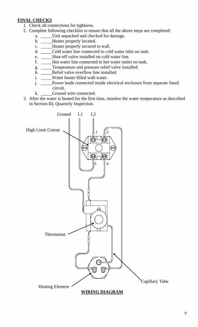
Ground L1 L2
High Limit Cutout
Thermostat
Capillary Tube
Heating Element WIRING DIAGRAM
1
3 4
2
10
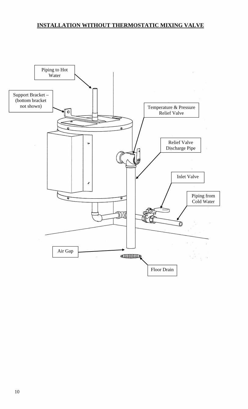
INSTALLATION WITHOUT THERMOSTATIC MIXING VALVE
Piping to Hot Water
Support Bracket – (bottom bracket
not shown)
Piping from Cold Water
Floor Drain
Air Gap
Inlet Valve
Relief Valve Discharge Pipe
Temperature & Pressure Relief Valve
11
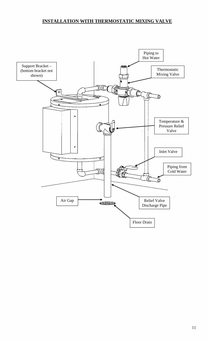
INSTALLATION WITH THERMOSTATIC MIXING VALVE
Thermostatic Mixing Valve
Piping to Hot Water
Support Bracket – (bottom bracket not
shown)
Air Gap
Floor Drain
Relief Valve Discharge Pipe
Temperature & Pressure Relief
Valve
Piping from Cold Water
Inlet Valve

12
SECTION III - SCHEDULED MAINTENANCE AND OPERATION
WARNING / CAUTION
Before performing any maintenance procedure, make certain power supply is OFF and cannot accidentally be turned on. Exposure to 125°F or hotter water can cause scalding injuries. Appropriate caution must be taken when using hot water. Special supervision must be given to those who cannot react quickly such as children, invalids, or elderly persons. MAINTENANCE AND OPERATION The water heater is automatic in its operation. It will maintain a full tank of water at the temperature setting of the thermostat. The water heater should not be turned on without first making sure that the tank is full of water and that all air has been released. FREEZING The tank should be fully drained in the event the electricity has been turned off and if there is danger of freezing. QUARTERLY INSPECTION 1. Water temperature regulation.
a. Let water heater completely heat to a designated thermostat setting. b. After thermostat satisfies (i.e., when the thermostat actually clicks off), draw water from
heater. c. Measure the maximum temperature with an accurate thermometer. d. If the temperature is above the safe limits for your circumstances call a service man to
adjust or replace the control. 2. Lift test lever on relief valve and let water run through valve for a period of
approximately 10 seconds. This will help flush away any sediment that might build up in water passageways.
3. Inspect element flange for leakage as follows: a. Shut off Power Supply. b. Remove element housing cover. c. Visually inspect heating element for evidence of leaks. d. Rub finger around heating element and check for any evidence of moisture. If
moisture is present or a water drip is observed, follow procedure outlined in Section V.
4. Check for loose electrical connections. Tighten as necessary. ANNUAL INSPECTION 1. Flush tank as follows
a. Shut off power supply. b. Attach a hose to the drain valve installed in the cold water piping. c. Close valve on the cold water line to the heater. d. Open the drain valve and direct the water to a drain. e. Open hot water faucet to admit air into the tank. f. Close drain valve and hot water faucet. g. Open valve on the cold water line to the heater. h. Turn power supply ON.
13
LONG TERM SHUT DOWN 1. If the water heater is to remain idle for an extended period of time, the power and
water to the heater should be turned off to conserve energy. 2. The water heater and piping should be drained, if they might be subjected to freezing
temperatures. 3. After a long shutdown period, the heater's operations and controls should be checked
by qualified service personnel. 4. Make certain the water heater is filled before placing it in operation.
EMERGENCY
1. Should the heater be subject to flood, fire, or other damaging conditions, turn off the power and water to the heater.
2. DO NOT place water heater in operation again until it has been thoroughly checked by qualified service personnel.
SECTION IV – TROUBLESHOOTING
Symptom Probable Cause Corrective Action / Remedy No hot water Circuit breaker tripped at
source. Reset circuit breaker.
High limit switch tripped. Reset high limit switch. Loose wires. Tighten wires. Torque screws per
torque chart included in Section VI. Heating element inoperable. Check heating element operation by
clamping an ammeter around each wire to the element. The ampere reading should agree with the nameplate ‘AMP’ figure.
Low line voltage. Have source electrical system checked by an electrician.
Faulty thermostat. Move thermostat dial through full range. A definite ‘click’ should be heard. If not, replace thermostat.
Water temperature below settings at all times
Faulty thermostat. Check thermostat adjustment. Monitor thermostat as described in Section III, Quarterly Inspection. Replace if necessary.
Relief valve discharges continuously
Excessive temperature or pressure in tank
Temperature and pressure relief valves are made to operate if the water temperature exceeds 210°F or water pressure exceeds the pressure rating of the safety relief valve. If trouble is excessive temperature, then thermostat is not shutting off at the right setting and thermostat must be replaced.
14
SECTION V - SERVICING & REPLACEMENT OF PARTS
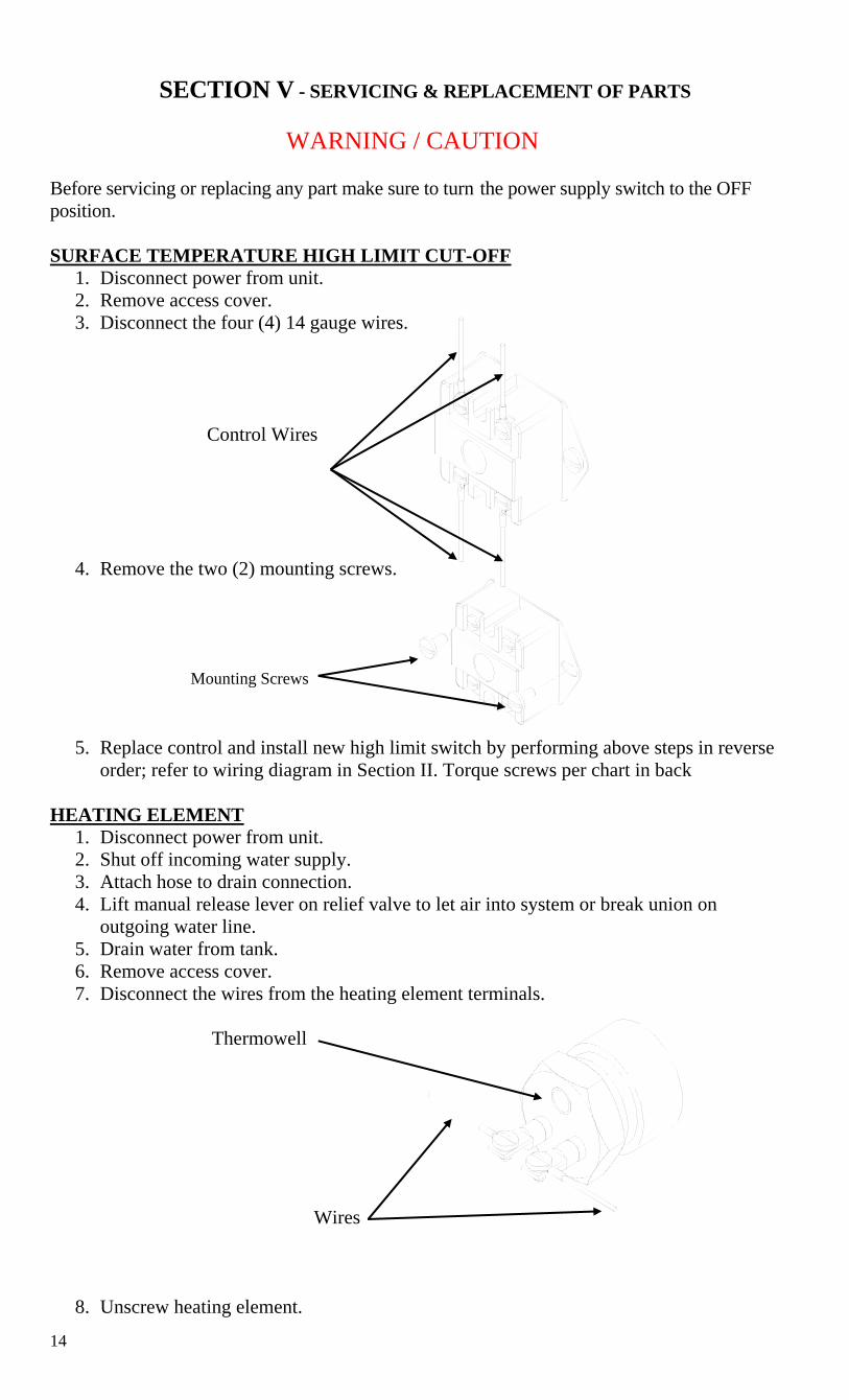
WARNING / CAUTION Before servicing or replacing any part make sure to turn the power supply switch to the OFF position. SURFACE TEMPERATURE HIGH LIMIT CUT-OFF
1. Disconnect power from unit. 2. Remove access cover. 3. Disconnect the four (4) 14 gauge wires.
Control Wires
4. Remove the two (2) mounting screws.
5. Replace control and install new high limit switch by performing above steps in reverse order; refer to wiring diagram in Section II. Torque screws per chart in back
HEATING ELEMENT
1. Disconnect power from unit. 2. Shut off incoming water supply. 3. Attach hose to drain connection. 4. Lift manual release lever on relief valve to let air into system or break union on
outgoing water line. 5. Drain water from tank. 6. Remove access cover. 7. Disconnect the wires from the heating element terminals.
Thermowell Wires
8. Unscrew heating element.
Mounting Screws

15
9. Withdraw element assembly. Tank Coupling Element Assembly
10. Install Teflon tape and insert new heating element. Thermowell must be above the heating element, in the 12 o’clock position.
11. Rewire element; refer to wiring diagram in Section II. Torque screws per chart in back.
12. Reinstall access cover. 13. Fill tank and check around element for any leaks.
THERMOSTAT
1. Disconnect power from unit. 2. Remove access cover and locate thermostat. 3. Disconnect the two (2) control wires.
Wires Capillary Tube
4. Remove capillary tube and bulb from thermowell in element. See previous page. 5. Remove mounting screw and knob. 6. Remove thermostat by sliding out from behind mounting bracket. 7. Replace thermostat using the reverse procedure; refer to wiring diagram in Section II.
Mounting Bracket
Mounting Screw

16
RELIEF VALVE 1. Disconnect power from unit. 2. Shut off incoming water supply. 3. Lift test lever on relief valve to relieve pressure in tank. 4. Disconnect overflow piping. 5. Unscrew relief valve, remove assembly and replace with new one. 6. Connect overflow piping. 7. Turn on incoming water supply and check for leaks. 8. Turn safety switch to ON position.
Test Lever Overflow Piping Outlet Tank Connection Temperature Probe

17
SECTION VI – WARRANTY
LIMITED WARRANTY 1. PRODUCT WARRANTY. Hubbell warrants the water heater it manufactures and its components (the "Product") to be free from defects in materials and workmanship, under normal use and service for the period of time identified below beginning from the date of installation, provided that the product is installed within three (3) months of date of shipment from Hubbell and when the Product is installed and maintained in accordance with Hubbell's written instructions (see operators manual for details). Owner must establish the Product's purchase date by means satisfactory to Hubbell in its sole discretion. TANK and COMPONENTS: One (1) year parts and labor TANK ONLY: Five (5) years Non Pro-Rated REPLACEMENT PARTS: Thirty (30) days parts only, no labor, from date of purchase SUCH WARRANTIES DO NOT COVER:
• Product failure (including but not limited to the tank and/or heating elements) caused by liming, sediment buildup, chemical corrosion, chlorine corrosion, or freezing.
• Product misuse, tampering or misapplication, accidental damage, improper installation or the application of improper voltage.
• Costs incurred for shipping, delivery, handling, and/or administrative charges. • For the tank warranty after the first year, all labor, shipping, installation costs, and
components (other than the tank) are the responsibility of the owner. • With respect to labor warranty within the first year, overtime, holiday, weekend or any
other non-standard labor rate. • Excessive and unreasonable labor rates and/or travel expenses as determined by
Hubbell in its sole discretion. THE FOREGOING WARRANTIES ARE EXCLUSIVE AND IN LIEU OF ANY OTHER WARRANTY, EXPRESSED OR IMPLIED, INCLUDING BUT NOT LIMITED TO ANY IMPLIED WARRANTY OR MERCHANTABILITY OR FITNESS FOR A PARTICULAR PURPOSE OR PATENT OR OTHER INTELLECTUAL PROPERTY RIGHT INFRINGEMENT. 2. LIMITATION OF REMEDIES AND DAMAGES. Hubbell's liability and Buyer's exclusive remedy hereunder will be limited solely, at Hubbell's option, to repair or replacement by a Hubbell authorized service agency (other than where Buyer is located outside of the United States or Canada, in which case Hubbell's liability and Buyer's exclusive remedy hereunder will be limited solely to replacement of part under warranty) with respect to any claim made within the applicable warranty period referred to above. Without limiting the generality of the foregoing, all warranty items shall be returned by Buyer, at its sole expense, to the Hubbell factory (45 Seymour Street Stratford, CT 06615) for replacement or repair. Hubbell reserves the right to accept or reject any such claim in whole or in part. Hubbell will not accept the return of any product without prior written approval from Hubbell, and all such approved returns shall be made at Buyer's sole expense. HUBBELL WILL NOT BE LIABLE, UNDER ANY CIRCUMSTANCES, FOR CONSEQUENTIAL OR INCIDENTAL DAMAGES, INCLUDING BUT NOT LIMITED TO LABOR COSTS OR LOST PROFITS RESULTING FROM THE USE OR INABILITY TO USE THE PRODUCTS OR FROM THE USE OF OR INABILITY TO USE THE PRODUCTS OR FROM THE PRODUCTS BEING INCORPORATED IN OR BECOMING A COMPONENT OF ANY OTHER PRODUCT OR GOODS.

18
NOTES

19
NOTES

20
P.O. BOX 288 STRATFORD, CT 06615-0288
PHONE: (203) 378-2659 FAX: (203) 378-3593
INTERNET: http://www.hubbellheaters.com/