commercial in confidence - esaemits.sso.esa.int/emits-doc/astriumlim/sentinel_1_ses_tgu/s1-li... ·...
TRANSCRIPT

COMMERCIAL IN CONFIDENCE
Sentinel-1
S1-LI-ASU-PL-0011Issue 1
Page 2 of 76
EADS Astrium Ltd owns the copyright of this document which is supplied in confidence and which shall not be used for any purpose other than that for which it is supplied and shall
not in whole or in part be reproduced, copied, or communicated to any person without written permission from the owner.
COMMERCIAL IN CONFIDENCE
Intentionally blank

COMMERCIAL IN CONFIDENCE
Sentinel-1
S1-LI-ASU-PL-0011Issue 1
Page 3 of 76
EADS Astrium Ltd owns the copyright of this document which is supplied in confidence and which shall not be used for any purpose other than that for which it is supplied and shall
not in whole or in part be reproduced, copied, or communicated to any person without written permission from the owner.
COMMERCIAL IN CONFIDENCE
Contents
1. INTRODUCTION ...........................................................................................................................................5 1.1 Scope .....................................................................................................................................................5
2. APPLICABLE DOCUMENTS ........................................................................................................................5 2.1 Normative Documents............................................................................................................................5 2.2 Informative Documents ..........................................................................................................................5
3. ACRONYMS AND ABBREVIATIONS ...........................................................................................................6
4. DEFINITIONS..............................................................................................................................................34 4.1 System..................................................................................................................................................34 4.2 C-SAR Instrument ................................................................................................................................36 4.3 Spacecraft and Platform.......................................................................................................................42 4.4 Ground Segment ..................................................................................................................................45 4.5 Lifetime .................................................................................................................................................52
5. BACKSCATTERING MODEL......................................................................................................................54 5.1 Terrain ..................................................................................................................................................54 5.2 Ocean ...................................................................................................................................................54
6. REFERENCE FRAMES ..............................................................................................................................56
7. SPACECRAFT NOMINAL MODES & POINTING DEFINITIONS...............................................................60
8. PHASE AND AMPLITUDE ERRORS..........................................................................................................62 8.1 Absolute Within Pulse Errors................................................................................................................63 8.2 Relative Within Pulse Errors.................................................................................................................63 8.3 Pulse to Pulse Errors over Coherent Subaperture...............................................................................63 8.4 Stability over time intervals...................................................................................................................65
9. OTHER DEFINITIONS ................................................................................................................................66
10. ECSS TERMS ...........................................................................................................................................69 10.1 ECSS-E-10-02A .................................................................................................................................69 10.2 ECSS-E-10-03A .................................................................................................................................70 10.3 ECSS-E-20A.......................................................................................................................................74
11. COMMERCIAL ..........................................................................................................................................75

COMMERCIAL IN CONFIDENCE
Sentinel-1
S1-LI-ASU-PL-0011Issue 1
Page 4 of 76
EADS Astrium Ltd owns the copyright of this document which is supplied in confidence and which shall not be used for any purpose other than that for which it is supplied and shall
not in whole or in part be reproduced, copied, or communicated to any person without written permission from the owner.
COMMERCIAL IN CONFIDENCE
Intentionally blank

COMMERCIAL IN CONFIDENCE
Sentinel-1
S1-LI-ASU-PL-0011Issue 1
Page 5 of 76
EADS Astrium Ltd owns the copyright of this document which is supplied in confidence and which shall not be used for any purpose other than that for which it is supplied and shall
not in whole or in part be reproduced, copied, or communicated to any person without written permission from the owner.
COMMERCIAL IN CONFIDENCE
1. INTRODUCTION
1.1 Scope This document lists acronyms, abbreviations and definitions relevant to the Sentinel-1 SES programme context. Acronyms and abbreviations appear as a single list in alphabetical order in section 3. Specific Sentinel definitions appear in section 3. Also included are the definitions of the Backscattering Model, Reference Frames and spacecraft Modes and Pointing taken from IRD01. In addition, definitions from certain ECSS standards are given. The document concludes with some commercial definitions.
2. APPLICABLE DOCUMENTS
2.1 Normative Documents None
2.2 Informative Documents IRD01 ES-RS-ESA-SY-0001 issue 1.1 System Requirements Document IRD02 H. Fiedler, E. Boerner, J. Mittermayer, G. Krieger. “Total Zero Doppler Steering”. Paper
submitted for patent. German Aerospace Center (DLR)

COMMERCIAL IN CONFIDENCE
Sentinel-1
S1-LI-ASU-PL-0011Issue 1
Page 6 of 76
EADS Astrium Ltd owns the copyright of this document which is supplied in confidence and which shall not be used for any purpose other than that for which it is supplied and shall
not in whole or in part be reproduced, copied, or communicated to any person without written permission from the owner.
COMMERCIAL IN CONFIDENCE
3. ACRONYMS AND ABBREVIATIONS
A A/D Analogue to Digital AAA Active Array Antenna AB Arbitration Board ABCL As Built Configuration List ABD Airborne Demonstrator AC Alternating Current ACCD Accumulation Charged Coupled Device ACF Archive and Catalogue Facility ACG Analyse, Change, Generate ACK Acknowledgement ACQ Spacecraft Acquisition Mode AD Analogue to Digital AD Applicable Document ADC Analogue to Digital Converter ADD Architectural Design Document ADP Acceptance Data Package AF Acquisition Facility AFT Abbreviated Function Test AGC Automatic Gain Control AHA Actuator Hinge Assembly AHT Accurate Housekeeping Temperature AIT Assembly Integration and Test AIV Assembly, Integration and Verification AIVT Assembly, Integration, Verification and Test AL Acceptance Levels ALOS Advanced Land Observing Satellite AM Amplitude Modulated AME Attitude Measurement Error AMI Active Microwave Instrument AN ANalog acquisition interface ANC Analogue conditioned AND Alphanumeric Displays ANSI American National Standards Institute Ant Antenna AO Announcement of Opportunity AOCS Attitude and Orbit Control System AOS Acquisition of Signal AOS Advanced Orbiting Systems AOS Availability Of Signal APE Absolute Pointing Error APG Antenna Pattern Generator API Application Program(ming) Interface APID Application Process Identifier APM Antenna Pattern Modelling APO Antenna Pattern Optimisation Software APSYS Antenna Pattern Synthesis Software AR Acceptance Review

COMMERCIAL IN CONFIDENCE
Sentinel-1
S1-LI-ASU-PL-0011Issue 1
Page 7 of 76
EADS Astrium Ltd owns the copyright of this document which is supplied in confidence and which shall not be used for any purpose other than that for which it is supplied and shall
not in whole or in part be reproduced, copied, or communicated to any person without written permission from the owner.
COMMERCIAL IN CONFIDENCE
ARB Anomaly Review Board ARE Absolute Rate Error AS Antenna Subsystem ASAR Advanced Synthetic Aperture Radar (sensor onboard ENVISAT) ASCII American Standard Code for Information Interchange ASH Acquisition and Safe Hold ASIC Application Specific Integrated Circuit ASM Assembly Manager ASM Attitude Steering Mode ASR Array Switching Regulator AST Autonomous Star Tracker ASW Application Software ASY Assembly AT Acceptance Level Test ATM Atmospheric ATOX Atomic Oxygen ATP Automatic Test Procedure ATS Acquisition and Transcription System ATT Attitude AU Astronomical Unit AWG American Wire Gauge
B b bit B Byte (eight bits) B/U Backup BA Baffle and Thermal Hardware BAQ Block Adaptive Quantisation BATT Battery BB Baseband BB Breadboard BBE Base Band Equipment BBIC BBE Interconnect BC Bus Controller BCT Beam Control Table BD Block Diagram BER Bit Error Rate BEX Beam Expander BGA Ball Grid Array BIT Built In Test BLD Bilevel Digital BM Balance Mass BNR Bus Non Regulated BOL Beginning Of Life BP Basic Product BPS/bps Bits per Second BPSK B-Phase Shift Keying (modulation method) BR Bus Regulated BRC Basic Repeat Cycle BRP Back Relief Pressure BST Beam Steering Table

COMMERCIAL IN CONFIDENCE
Sentinel-1
S1-LI-ASU-PL-0011Issue 1
Page 8 of 76
EADS Astrium Ltd owns the copyright of this document which is supplied in confidence and which shall not be used for any purpose other than that for which it is supplied and shall
not in whole or in part be reproduced, copied, or communicated to any person without written permission from the owner.
COMMERCIAL IN CONFIDENCE
BSW Basic Software BUSW Boot-up S/W BW Bandwidth
C C&C Command and Control CAB Change Appeal Board CAD Computer Aided Design CADM Configuration And Data Management CADU Channel Access Data Unit CAE Computer Aided Engineering CAF Cluster Angewandte Fernerkundung Cal Calibration CAN Controller Area Network CAPS C-SAR Antenna Power Supply CAT Category CBCP Current Baseline Cost Plan CBH Cat Bed Heater CBS Cost Breakdown Structure CBS Standard OBDH Bus Coupler (French version) CCB Configuration Control Board CCD Configuration Control Document CCE Control Circuit Encoding CCGA Ceramic Column Grid Array CCN Contract Change Notice CCS Command & Control Subsystem CCSDS Consultative Committee for Space Data Systems CD Coefficient of Drag CD Collision Detection CD, CD-R Compact Disk – Recordable CDAS Command and Data Acquisition Station CDKP Critical Design Key Point CDMU Control and Data Management Unit CDR Critical Design Review CD-ROM Compact Disc Read Only Memory CDS Correlated Double Sampling CE Central Electronics CE Chip Enable CE Conducted Emissions CEOS Committee on Earth Observation Satellites CESS Coarse Earth and Sun Sensor CESS Central Electronics Subsystem CETeF Central European Test Facilities CF Catalogue Facility CFE Customer Furnished Equipment CFI Customer Furnished Item CFRP Carbon Fibre Reinforced Plastic CGE Calibration Ground Equipment CHAMP CHAllenging Mini-satellite Payload CHKA Short-tem History Housekeeping Archive CHT Coarse Housekeeping Temperature

COMMERCIAL IN CONFIDENCE
Sentinel-1
S1-LI-ASU-PL-0011Issue 1
Page 9 of 76
EADS Astrium Ltd owns the copyright of this document which is supplied in confidence and which shall not be used for any purpose other than that for which it is supplied and shall
not in whole or in part be reproduced, copied, or communicated to any person without written permission from the owner.
COMMERCIAL IN CONFIDENCE
CI Cloud Imager CI Configuration Item CI Critical Items CI-DDR Critical Items Detailed Design Review CIDL Configuration Item Data List CIL Critical Item List CIP Catalogue Interoperability Protocol CIR Consolidation Phase Intermediate Review CI-TRR Critical Items Test Results/Readiness Review CL Current Limiter CLCW Command Link Control Word CLS Clear to Send CLTU Command Link Transmission Unit CM Centre of Mass CM Common Mode CM Configuration Management CMCF Central Monitoring and Control Facility CMD Command CME Coefficient of Moisture Expansion CMOS Complementary Metal Oxide Semiconductor CMP Configuration Management Plan CMS Coordination and Management System CNC Computer Numerical Control CoC Certificate of Conformance/Conformity CoG Centre of Gravity CoM Centre of Mass COMMS Communications COMP Complement COP Command Operation Procedure CORE Common Radar Elements COS Checkout System COTS Commercial Off-The-Shelf CP Central (or Control) Processor CP Change Proposal CP Cold Plate CP Commissioning Phase CPDU Command Pulse Distribution Unit CPS Combined Propulsion Sub-system CPT Comprehensive Performance Test CPU Central Processing Unit CQFP Ceramic Quad Flat Pack CR Change Request CR Corner Reflector CRB Change Review Board CRC Cyclic Redundancy Code CRC Cyclic Redundancy Check CRD Customer Requirements Document CRESS CORE Radar Electronics Subsystem CRP Contingency Recovery Procedure CS Chip Select

COMMERCIAL IN CONFIDENCE
Sentinel-1
S1-LI-ASU-PL-0011Issue 1
Page 10 of 76
EADS Astrium Ltd owns the copyright of this document which is supplied in confidence and which shall not be used for any purpose other than that for which it is supplied and shall
not in whole or in part be reproduced, copied, or communicated to any person without written permission from the owner.
COMMERCIAL IN CONFIDENCE
CS Conducted Susceptibilities CSA Contact Surface Area C-SAR C-Band SAR CSG Clock Signal Generator CSI Customer Source Inspection CSL Configuration Status List CSN Calibration Switching Network CSSRD Customer Services Support Requirements Document CT Calibration Target CTC Calibration Target Control CTC Cost to Completion CTE Coefficient of Thermal Expansion CTRL ConTRoL CTS Coax Transfer Switch CVCM Collected Volatile Condensable Material CVD Chemical Vapour Deposition CVM Converter Module CW Continuous Wave CWL Calibration Window Length
D DA Direct Access DAC Digital to Analogue Converter DAC Direct Access Customer DAM Deployed Acquisition Mode DAP Direct Access Partner DAS Direct Access Station DAS Direct Archive System DA-SP Direct Access Service Providers DAT Digital Audio Tape DataNet DLR/GSOC protocol layer DB Database dB decibel DBMS Database Management System DC Direct Current DCE Data and Control Electronics DCG Document Contents Guidelines DCL Declared Components List DCM Deployment Control Module DCN Document Change Notice DCP Deployed/Deployment Contact Point DCR Document Change Request DCU Deplyment Control Unit DD Design and Development DD&AIV Design, Development & Assembly, Integration and Verification DDF Dependability Data File DDF Design Definition File DDVP Design, Development and Verification Plan DE Distributing Entity DEC Digital Equipment Corporation DEM Deployment Mechanism

COMMERCIAL IN CONFIDENCE
Sentinel-1
S1-LI-ASU-PL-0011Issue 1
Page 11 of 76
EADS Astrium Ltd owns the copyright of this document which is supplied in confidence and which shall not be used for any purpose other than that for which it is supplied and shall
not in whole or in part be reproduced, copied, or communicated to any person without written permission from the owner.
COMMERCIAL IN CONFIDENCE
DEM Digital Elevation Model DEP Spacecraft Deployment Mode DES Data Exchange Server DES Data Encryption Standard DESA X-Band SAR Demonstrator DEU Detection Electronic Units DF Dissemination Facility DFR Detection Front-end Radiator DFU Detection Front end Unit DHS Data Handling System DID Design and Interface Document DIL Deliverable Item List DIL Dual In-Line DIMS Data and Information Management System DIP DIPlexer DJF Design Justification File DL Downlink DLC Data Length Code DLR Deutsches Zentrum für Luft- und Raumfahrt e.V. DM Development Model DM Differential Mode DMA Defence Mapping Agency DML Declared Materials List DMM Digital Multimeter DMP Dump (attribute that identifies data originating from mass memory) DMPL Declared Mechanical Parts List DMSS Data Management Subsystem DMU Digital Mock-Up DMZ De-militarised Zone (Network Security Term) DOF Degree of Freedom DPA Destructive Physical Analysis DPL Declared Processes List DRA Dual Receive Antenna DRB Delivery Review Board DRB Distribution and Regulation Board DRD Detection Raw Data DRD Document Requirements Definition DRDL Detection Raw data Link DRL Document Requirements List DS Digital Serial acquisition DSID Data Structure ID DSL Document Status List DSPG Distributed Star-Point Grounding DT Data Take DTAR Distributed Target Ambiguity Ratio DTC Direct TeleCommand DTED-1/2 Digital Terrain Elevation Data (in accuracy levels 1 and 2) DTM Digital Terrain Model DTS Data Transfer System (GSOC) DTS Deployment Test System

COMMERCIAL IN CONFIDENCE
Sentinel-1
S1-LI-ASU-PL-0011Issue 1
Page 12 of 76
EADS Astrium Ltd owns the copyright of this document which is supplied in confidence and which shall not be used for any purpose other than that for which it is supplied and shall
not in whole or in part be reproduced, copied, or communicated to any person without written permission from the owner.
COMMERCIAL IN CONFIDENCE
DU Detection Units DUT Design Under Test DUT Device Under Test DV Delta Velocity DVB Digital Video Broadcast DVD-R Digital Video Disk - Recordable DWP Data Window Position
E E/V EnVironmental (Design and Test) E2E End To End EAC Estimate at Completion EAD Electrostatic Arch Discharge EADS European Aeronautic Defence and Space Company EAF Event Detection and Action Execution Function EAP Existing Acquisition Product EBB Elegant Bread-Board EC External Calibration EC-BAQ Entropy-Constrained Block Adaptive Quantisation ECC Event Control Code ECC Error Correction Code ECEF Earth Centred Earth Fixed ECI Earth Centred Inertial ECL Emitter Coupled Logic ECO Engineering Change Order ECP Engineering Change Proposal ECR Engineering Change Request ECSS European Co-operation for Space Standardisation ED External Data Interface EDAC Error Detection and Correction EEC Enhanced Ellipsoid Corrected EEE Electrical and Electronics Engineering EEE Electrical, Electronic and Electromechanical EEPROM Electrically Erasable and Programmable Read Only Memory (E2PROM) EES End to End Simulator EfM Electrical functional Model EFM Encryptor Formatter Module EFN Elevation Feed Network EGRP Electrical Ground Reference Plane EGRS Electrical Ground Reference Structure EGSE Electrical Ground Support Equipment EHAR Electrical Harness EHB Error Handbook EIA Electronics Industries Association EICD Electrical Interface Control Document EIDP End Item Data Pack EIRP Earth Integrated Receive Power EIRP Effective Isotropic Radiated Power EM Engineering Model EMC Electro-Magnetic Compatibility EMCS EGSE & Mission Control System

COMMERCIAL IN CONFIDENCE
Sentinel-1
S1-LI-ASU-PL-0011Issue 1
Page 13 of 76
EADS Astrium Ltd owns the copyright of this document which is supplied in confidence and which shall not be used for any purpose other than that for which it is supplied and shall
not in whole or in part be reproduced, copied, or communicated to any person without written permission from the owner.
COMMERCIAL IN CONFIDENCE
EMI Electro-Magnetic Interference EN System & Engineering ENL Equivalent Number of Looks EO Earth Observation EOC End of Charge EOL End Of Life EOM Electro-Optic Modulator EOS Earth Observing System EOWEB Earth Observation on the WEB (Web Gateway of ISIS and MUIS) EPP Electrical Preparatory Programme EPPL European Preferred Parts List EPROM Electrically Programmable ROM EPS Electrical Power System EQM Engineering Qualification Model EQSOL Equipment Switch Off Line ERS European Remote Sensing Satellite ERT Earth Received Time ES Electrical Systems ESA European Space Agency ESA MM ESA Multi-Mission ESA/ESRIN European Space Agency in Italy ESATAN ESA Thermal Analysis…. ESD Electrostatic Discharge ESE DLR/GSOC Enhanced System Environment ESOC European Space Operations Centre ESP Electrical Support Programme ESRIN European Space Research INstitute ESTEC European Space Technology Centre ETRS European Terrestrial Reference System EU Electrical Units EUT Equipment under Test EV EnVironmental (Design and Test) EVT Environmental and Test
F FA Functional Analysis FAAD Flight Attitude Anomaly Detector FAR Flight Acceptance Review FAR Frame Acceptance and Reporting FAR Frame Analysis Report FCL Foldback Current Limiter FCP Flight Control Procedure FCT Flight Control Team FCT Full Characterisation Test FCV Flow Control Valve FD Flight Dynamics FDIR Failure Detection, Isolation and Recovery FDL Flight Design Load FDLL Flight Design Limit Load FDLU Flight Design Load Ultimate FDLY Flight Design Load Yield

COMMERCIAL IN CONFIDENCE
Sentinel-1
S1-LI-ASU-PL-0011Issue 1
Page 14 of 76
EADS Astrium Ltd owns the copyright of this document which is supplied in confidence and which shall not be used for any purpose other than that for which it is supplied and shall
not in whole or in part be reproduced, copied, or communicated to any person without written permission from the owner.
COMMERCIAL IN CONFIDENCE
FDS Flight Dynamics System FDV Fill/Drain Valve FDVV Fill & Drain/Vent Valve FE Finite Element FEC Forward Error Correction FECW Frame Error Control Word FEM Finite Element Model FESS Front End Subsystem FET Field Effect Transistor FFM Flip Flop Mechanism FFT Fast Fourier Transform FFT-
ECBAQ Fast Fourier Transform-Entropy Constrained Block Adaptive Quantisation
FGSE Fuelling Ground Support Equipment FHP First Header Pointer FIFO First In, First Out FLE Fuel Loading Equipment FLL Flight Limit Load FM Flight Model FMECA Failure Modes Effects and Criticality Analysis FOF Flight Operations Facility FOP Flight Operations Plan or Procedures FOS Flight Operations Segment FOT Flight Operations Team FOV Field of View FPGA Field Programmable Gate Array FPM Fine Pointing Mode FPO Focal Plane Optics FPT Full Functional and Performance Test FR Final Review FRD Functional Requirements Document FRED Framed Raw Expanded Data FRO FRont Optics FRR Flight Readiness Review FRU Front end Repeater Unit FS Flight Spare FSR Free Spectral Range FTA Fault Tree Analysis FTP File Transfer Protocol FVV Fill and Vent Valve FW Firmware FWHM Full Width at Half Maximum
G GA General assembly Ga As Gallium Arsenide Gbyte Gigabyte GCC Ground Control Centre GCN Ground Communications Network GCN-P Ground Communication Network PGS GCOS Global Climate Observing System

COMMERCIAL IN CONFIDENCE
Sentinel-1
S1-LI-ASU-PL-0011Issue 1
Page 15 of 76
EADS Astrium Ltd owns the copyright of this document which is supplied in confidence and which shall not be used for any purpose other than that for which it is supplied and shall
not in whole or in part be reproduced, copied, or communicated to any person without written permission from the owner.
COMMERCIAL IN CONFIDENCE
GCS Ground Communications Subnet GDI Grounding and Isolation GDIR General Design and Interface Requirement GDP Global Data Pool GDS DLR/GSOC Ground Data System GEC Geocoded Ellipsoid Corrected GFRP Glass Fibre Reinforced Plastic Ghe Helium Gas GHz Gigahertz GIP Gateway Interoperable Protocol GLOBE Global Land One-KM Base Elevation Data GLONASS GLObal'naya Navigatsionnay Sputnikovaya Sistema (Russian GPS) GMES Global Monitoring for Environment and Security GMFE Generic Modular Front End GMM Geometric Mathematical Model GMT Greenwich Mean Time GNC Guidance, Navigation & Control GND Ground GNSS Global Navigation Satellite System GOP Ground Operations Plan GOS Global Observing System GPIO General Purpose Input Output GPS Global Positioning System GPWG Grid Point Weight Generator GRACE Gravity Recovery and Climate Experiment GRC Greenwich Rotating non-inertial co-ordinates (earth centred) GRD Graphic Display (line plot) GRP Glass Reinforced Plastic GS Ground Station GS, G/S Ground Segment GSBD Ground Segment Baseline Definition (Document) GSCDR Ground Segment Critical Design Review GSE Ground Support Equipment GSICD Ground to Spacecraft Interface Control Document GSN Ground Station Network GSOC German Space Operations Centre GSOM Ground Segment and Operations Manager GSOPR Ground System and Operation Principles and Requirements GSOV Ground Segment Operational Validation GSPDR Ground Segment Preliminary Design Review GSRR Ground Segment Requirements Review GSRS Ground Segment Requirements Specification GSS Ground Segment Supplier GSTL Ground System Test Leader GSTS Ground Station System GSTS-M&C Ground Station System - Monitoring and Control GSTS-ME Ground Station System - Mission Exploitation GSTS-SSC Ground Station System - Space Segment Control GSTS-SSC Space Segment Control Station GSTVVR Ground Segment Technical Verification and Validation Review

COMMERCIAL IN CONFIDENCE
Sentinel-1
S1-LI-ASU-PL-0011Issue 1
Page 16 of 76
EADS Astrium Ltd owns the copyright of this document which is supplied in confidence and which shall not be used for any purpose other than that for which it is supplied and shall
not in whole or in part be reproduced, copied, or communicated to any person without written permission from the owner.
COMMERCIAL IN CONFIDENCE
GSTVVRR Ground Segment Technical Verification and Validation Readiness Review GT Green Tag GT Ground Target GTC Geocoded Terrain Corrected GTP Generic TM processor GUI Graphical User Interface
H H Horizontal Polarisation
H/K or HK Housekeeping Data H/W or HW Hardware HA Hazard Analysis HAR Harness HCI Human-Computer Interaction HDBK Hand Book HDDT High Density Data Tape HDF Hierarchical Data Format HFA History File Archive HH Linear Polarisation, horizontal at transmit, horizontal at receive HiSEEN High Speed ESA EO Network HK Housekeeping HKOBS Housekeeping and observation HKTM HouseKeeping TeleMetry HLOS Horizontal Line of Sight HMI Human-Machine Interface HP Heat Pipe HPC High Priority Command HPC High Power Command HPR Hardware Problem Report HPT High Power Transistor HR Harness HR Institut für Hochfrequenztechnik und Radarsysteme HRDS High Rate Data Stream HRM Hold-down and Release Mechanism HRX High Rate Data Extracted Parameters HS Heat Sink HSIA Hardware/Software Interaction Analysis HTTP Hyper Text Transfer Protocol HV Linear Polarisation, horizontal at transmit, vertical at receive HW or H/W Hardware Hz Hertz
I I In-phase I Input I/F InterFace I/O Input/Output IABG Industrieanlagen Betriebs-Gesellschaft IAM Initial Acquisition Mode IBR Instrument Baseline Review IC Instrument Core IC/ICAL Internal Calibration

COMMERCIAL IN CONFIDENCE
Sentinel-1
S1-LI-ASU-PL-0011Issue 1
Page 17 of 76
EADS Astrium Ltd owns the copyright of this document which is supplied in confidence and which shall not be used for any purpose other than that for which it is supplied and shall
not in whole or in part be reproduced, copied, or communicated to any person without written permission from the owner.
COMMERCIAL IN CONFIDENCE
ICB Internal Control Bus ICD Interface Control Document/Drawing ICDR Instrument Critical Design Review ICE Integrated Central Electronics ICF Instrument Calibration Facility ICF InterChangeable Format ICG Instrument Command Generator ICH Instrument Command History ICM Instrument Control Module ICM Instrument Command and Monitoring bus ICM Instrument Control and Monitoring ICS Instrument Calibration Segment ICS Instrument Operations and Calibration Segment ICU Instrument Control Unit ICV Inter Centre Vector ID Identification, Identity IDD Integration, Design and Development IDE Identifier Extension IDRB Instrument Delivery Review Board IEB Instrument External Baffle IEC International Electrotechnical Commission IEEE Institute of Electrical and Electronics Engineers I/F Interface IF Intermediate Frequency IFE Intermediate Frequency Equipment IFESS Integrated Front End Subsystem IFM Interferometer IFOV Instantaneous Field-Of-View IFU Interface-to-Units Module IGP ICS (2) Guide Protocol IGRF International Geomagnetic Reference Frame IGS International GPS Service ILZPF Ingestion and Level 0 Processing Facility IM Isostatic Mount IMD Isostatic Mounting Device IMF Remote Sensing Technology Institute IMO Inverted Mode Operation IMR Instrument Master Reference IMRC Instrument Master Reference Cube IMU Inertia Measurement Unit (Gyro) INS Institute of Navigation, University Stuttgart InSAR Interferometric Synthetic Aperture Radar INT Interrupt Int Internal IO or I/O Input/Output IOCS Interoperable Catalogue System IOD In-orbit Delivery IOF Instrument Operations Facility IOGT I/O for General functions Sentinel-1 IOOR In-Orbit Operations Review

COMMERCIAL IN CONFIDENCE
Sentinel-1
S1-LI-ASU-PL-0011Issue 1
Page 18 of 76
EADS Astrium Ltd owns the copyright of this document which is supplied in confidence and which shall not be used for any purpose other than that for which it is supplied and shall
not in whole or in part be reproduced, copied, or communicated to any person without written permission from the owner.
COMMERCIAL IN CONFIDENCE
IOPS/IOS Instrument Operations Segment IOPT I/O for Propulsion chain Sentinel-1 IOST I/O for Servicing equipment Sentinel-1 IOT In Orbit Testing IP Intellectual Property IP Internet Protocol IPDU Instrument Power Distribution Unit IPFD Input Flux Density IPSU Instrument Power Supply Unit IPU Instrument Processing Unit IR Infra-Red IRD Informative Reference Document IRD Interface Requirement Document IRF Impulse Response Function IRQ Interrupt Request ISA Industry Standard Architecture ISDN Integrated Services Digital Network ISLR Integrated Sidelobe Ratio ISO International Organisation for Standardisation ISP Instrument Source Packet IST Integrated System Test ISV Independent Software Validation ISVF Instrument Software Validation Facility ISVV Independent Software Verification and Validation ITRF International Terrestrial Reference Frame ITT Invitation To Tender ITU International Telecommunications Union IU Integer Unit IUT Item Under Test IVR Instrument Verification IVV/IV&V Integration, Verification and Validation
J JEDEC Joint Electron Device Engineering Council JTAG Joint Test Action Group
K k 1024 multiplier prefix K Kelvin K1 Control Room 1 kbps Kilo bit per second kHz Kilo Hertz KIP Key Inspection Point KIP Key Inspection Point KMF Key Management Facility KO Kick-Off
L L0 Processing Level 0 according to CEOS definition L1b Processing Level 1b according to CEOS definition LA Launcher LAF Long Term Archiving Facility LAN Local Area Network

COMMERCIAL IN CONFIDENCE
Sentinel-1
S1-LI-ASU-PL-0011Issue 1
Page 19 of 76
EADS Astrium Ltd owns the copyright of this document which is supplied in confidence and which shall not be used for any purpose other than that for which it is supplied and shall
not in whole or in part be reproduced, copied, or communicated to any person without written permission from the owner.
COMMERCIAL IN CONFIDENCE
LAR Launch Acceptance Review LAT Lot Acceptance Testing LAU Spacecraft Launch Mode LB Local Bus LCC Library Configuration Control LCDA Launcher Coupled Dynamic Analysis LCE Leak Check Equipment LCL Latching Current Limiter LCLK Low (rate) CLocK LDO Low DropOut LDTS Large Data Transfer Service LED Light Emitting Diode LEO Low Earth Orbit LEOP Launch and Early Operations/ Launch and Early Orbit Phase LET Linear Energy Transfer LHCP Left Hand Circular Polarisation LIDAR Light Detection And Ranging LISN Line Impedance Simulation Network LLI Long Lead Items LMCF Local Monitoring and Control Facility LN2 Liquid Nitrogen LNA Low Noise Amplifier LO Local Oscillator LOS Line Of Sight LOS Loss Of Signal LOV Local Orbit Vector LRR Launch Readiness Review L-SAR L-band Synthetic Aperture Radar LSB Least Significant Bit LT Long Term (Requirement) LTAN Local Time Ascending Node LTDB Long-term Database LTP Long-term Planning = Strategic Planning LTSM Long-term System Monitoring LV Latch Valve LV Launch Vehicle LVA Launch Vehicle Adapter LVAU Launch Vehicle Authority LVDS Low Voltage Differential Signalling LVLH Local Vertical Local Horizontal LVS Launch Vehicle System
M M Mega 1024k multiplier prefix M&C Monitoring and Control MAG Magnetometer MAIT Manufacturing, Assembly, Integration and Test MAP Multiplexed Access Point Mbps Mega bit per second MByte MegaByte MC Marginally Compliant

COMMERCIAL IN CONFIDENCE
Sentinel-1
S1-LI-ASU-PL-0011Issue 1
Page 20 of 76
EADS Astrium Ltd owns the copyright of this document which is supplied in confidence and which shall not be used for any purpose other than that for which it is supplied and shall
not in whole or in part be reproduced, copied, or communicated to any person without written permission from the owner.
COMMERCIAL IN CONFIDENCE
MCM Multi Chip Module MCMD Macrocommand MCPC Master Channel Frame Count Mcps Mega Complex Samples Per Second MCS Mission Control System MD Mass Dummy MDFE Mission Dependant Filter Equipment MDVE Model Development and Verification Environment MEC Mission Exploitation Centre MEIP Maximum Expected Inlet Pressure MEOP Maximum Expected Operating Pressure MES Mission Exploitation System MF Maintenance File MGD Multi Look Ground Range Detected MGSE Mechanical Ground Support Equipment MGT Management File MHz Megahertz MIB Minimum Impulse Bit MIB Mission Information Base (TM/TC display database) MICD Mechanical Interface Control Document MIMO Multivariate Input Multivariate Output MIN Minimum MIP Mandatory Inspection Point ML Master Library ML Memory Load MLC Memory Load Command MLI Multi-Layer Insulation MM Mass Memory module MM Mass Memory board MM&C Mission Management and Control MMA Memory Metal Alloy MMC Mission Master Catalogue MMFU Memory & Formatting Unit MMI Man-Machine Interface MMIC Monolithic Microwave Integrated Circuit MMU Mass Memory Unit MOC Mission Operations Centre MOCD Mission Operations Concept Document MOD Mission Operations Director MODIS Moderate Resolution Imaging Spectroradiometer MoI Moment of Inertia MOIS Mission Operations Information System MoS Margin of Safety MOS Mission Operations Segment MOSFET Metal Oxide Silicon Field Effect Transistor MOT Mission Operations Team MOTL Mission Operations Team Lead MOU Memorandum of Understanding MPCB Materials & Processes Control Board MPF Mission Planning Facility

COMMERCIAL IN CONFIDENCE
Sentinel-1
S1-LI-ASU-PL-0011Issue 1
Page 21 of 76
EADS Astrium Ltd owns the copyright of this document which is supplied in confidence and which shall not be used for any purpose other than that for which it is supplied and shall
not in whole or in part be reproduced, copied, or communicated to any person without written permission from the owner.
COMMERCIAL IN CONFIDENCE
MPS Mission Planning System MPS Mission Planning and Scheduling System MRB Material Review Board MRR Manufacturing Readiness Review MRT Mission Readiness Test MS Main Structure MS Material Specification MS Mechanical Systems MS Microsoft MSC Message Sequence Chart MSAR Multi-frequency SAR MSB Most Significant Bit MST Mission Simulation Test MSU Main Supply Unit MT Mid/Medium Term (Requirement) MTF Modulation Transfer Function MTL Mission Timeline MTM Magnetometer MTP Main Test Processor MTQ MagneTorQuer MTR Mid-term Review MTTR Mean Time to Repair MUIS Multi-Mission User Information Services
N N&R Nominal and Redundant N/A Not Applicable NAP New Acquisition Product NAPEOS Navigation Package for Earth Observation Satellites NASA National Aeronautics and Space Administration NB Narrow Band nBAQ Number of BAQ bits NC Not Compliant / Non Conformance NC Not Connected NCH Noise Characterisation NCI Non Critical Items NCR Non-Conformance Report NCTRS Network Controller Transport and Routing System NDA Non-Disclosure Agreement NDIU Network Data Interface Unit NEs0/NEσ0 Noise Equivalent Sigma Nought NESZ Noise Equivalent Sigma Zero NIR Near Infra-Red NM Normal Mode NOCC Network Operations Control Centre NOP Non-Operating NRB Non-Conformance Review Board NRD Normative Reference Document NRE Non-Recurring Expenditure NRT Near-Real Time NRZ Non Return to Zero
COMMERCIAL IN CONFIDENCE
Sentinel-1
S1-LI-ASU-PL-0011Issue 1
Page 22 of 76
EADS Astrium Ltd owns the copyright of this document which is supplied in confidence and which shall not be used for any purpose other than that for which it is supplied and shall
not in whole or in part be reproduced, copied, or communicated to any person without written permission from the owner.
COMMERCIAL IN CONFIDENCE
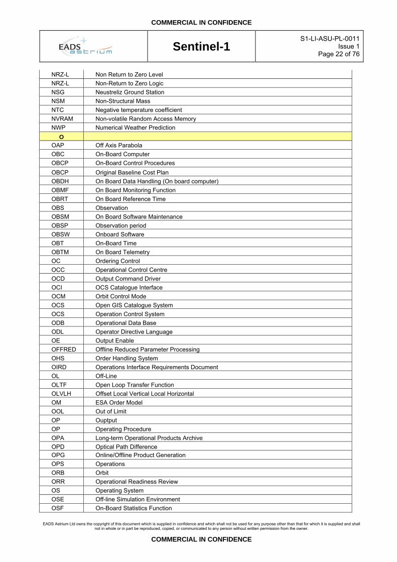
NRZ-L Non Return to Zero Level NRZ-L Non-Return to Zero Logic NSG Neustreliz Ground Station NSM Non-Structural Mass NTC Negative temperature coefficient NVRAM Non-volatile Random Access Memory NWP Numerical Weather Prediction
O OAP Off Axis Parabola OBC On-Board Computer OBCP On-Board Control Procedures OBCP Original Baseline Cost Plan OBDH On Board Data Handling (On board computer) OBMF On Board Monitoring Function OBRT On Board Reference Time OBS Observation OBSM On Board Software Maintenance OBSP Observation period OBSW Onboard Software OBT On-Board Time OBTM On Board Telemetry OC Ordering Control OCC Operational Control Centre OCD Output Command Driver OCI OCS Catalogue Interface OCM Orbit Control Mode OCS Open GIS Catalogue System OCS Operation Control System ODB Operational Data Base ODL Operator Directive Language OE Output Enable OFFRED Offline Reduced Parameter Processing OHS Order Handling System OIRD Operations Interface Requirements Document OL Off-Line OLTF Open Loop Transfer Function OLVLH Offset Local Vertical Local Horizontal OM ESA Order Model OOL Out of Limit OP Ouptput OP Operating Procedure OPA Long-term Operational Products Archive OPD Optical Path Difference OPG Online/Offline Product Generation OPS Operations ORB Orbit ORR Operational Readiness Review OS Operating System OSE Off-line Simulation Environment OSF On-Board Statistics Function
COMMERCIAL IN CONFIDENCE
Sentinel-1
S1-LI-ASU-PL-0011Issue 1
Page 23 of 76
EADS Astrium Ltd owns the copyright of this document which is supplied in confidence and which shall not be used for any purpose other than that for which it is supplied and shall
not in whole or in part be reproduced, copied, or communicated to any person without written permission from the owner.
COMMERCIAL IN CONFIDENCE
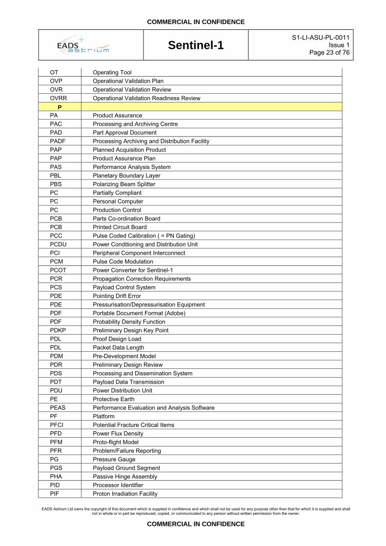
OT Operating Tool OVP Operational Validation Plan OVR Operational Validation Review OVRR Operational Validation Readiness Review
P PA Product Assurance PAC Processing and Archiving Centre PAD Part Approval Document PADF Processing Archiving and Distribution Facility PAP Planned Acquisition Product PAP Product Assurance Plan PAS Performance Analysis System PBL Planetary Boundary Layer PBS Polarizing Beam Splitter PC Partially Compliant PC Personal Computer PC Production Control PCB Parts Co-ordination Board PCB Printed Circuit Board PCC Pulse Coded Calibration ( = PN Gating) PCDU Power Conditioning and Distribution Unit PCI Peripheral Component Interconnect PCM Pulse Code Modulation PCOT Power Converter for Sentinel-1 PCR Propagation Correction Requirements PCS Payload Control System PDE Pointing Drift Error PDE Pressurisation/Depressurisation Equipment PDF Portable Document Format (Adobe) PDF Probability Density Function PDKP Preliminary Design Key Point PDL Proof Design Load PDL Packet Data Length PDM Pre-Development Model PDR Preliminary Design Review PDS Processing and Dissemination System PDT Payload Data Transmission PDU Power Distribution Unit PE Protective Earth PEAS Performance Evaluation and Analysis Software PF Platform PFCI Potential Fracture Critical Items PFD Power Flux Density PFM Proto-flight Model PFR Problem/Failure Reporting PG Pressure Gauge PGS Payload Ground Segment PHA Passive Hinge Assembly PID Processor Identifier PIF Proton Irradiation Facility
COMMERCIAL IN CONFIDENCE
Sentinel-1
S1-LI-ASU-PL-0011Issue 1
Page 24 of 76
EADS Astrium Ltd owns the copyright of this document which is supplied in confidence and which shall not be used for any purpose other than that for which it is supplied and shall
not in whole or in part be reproduced, copied, or communicated to any person without written permission from the owner.
COMMERCIAL IN CONFIDENCE
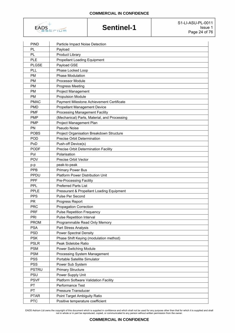
PIND Particle Impact Noise Detection PL Payload PL Product Library PLE Propellant Loading Equipment PLGSE Payload GSE PLL Phase Locked Loop PM Phase Modulation PM Processor Module PM Progress Meeting PM Project Management PM Propulsion Module PMAC Payment Milestone Achievement Certificate PMD Propellant Management Device PMF Processing Management Facility PMP (Mechanical) Parts, Material, and Processing PMP Project Management Plan PN Pseudo Noise POBS Project Organisation Breakdown Structure POD Precise Orbit Determination PoD Push-off Device(s) PODF Precise Orbit Determination Facility Pol Polarisation POV Precise Orbit Vector p-p peak-to-peak PPB Primary Power Bus PPDU Platform Power Distribution Unit PPF Pre-Processing Facility PPL Preferred Parts List PPLE Pressurant & Propellant Loading Equipment PPS Pulse Per Second PR Progress Report PRC Propagation Correction PRF Pulse Repetition Frequency PRI Pulse Repetition Interval PROM Programmable Read Only Memory PSA Part Stress Analysis PSD Power Spectral Density PSK Phase Shift Keying (modulation method) PSLR Peak Sidelobe Ratio PSM Power Switching Module PSM Processing System Management PSS Portable Satellite Simulator PSS Power Sub System PSTRU Primary Structure PSU Power Supply Unit PSVF Platform Software Validation Facility PT Performance Test PT Pressure Transducer PTAR Point Target Ambiguity Ratio PTC Positive temperature coefficient

COMMERCIAL IN CONFIDENCE
Sentinel-1
S1-LI-ASU-PL-0011Issue 1
Page 25 of 76
EADS Astrium Ltd owns the copyright of this document which is supplied in confidence and which shall not be used for any purpose other than that for which it is supplied and shall
not in whole or in part be reproduced, copied, or communicated to any person without written permission from the owner.
COMMERCIAL IN CONFIDENCE
PTR Post Test Review PTV Position Time & Velocity PTX Pressure Transducer PUP Parameter Update Process PUS Packet Utilisation Standard PVR Product Verification PVT Position, Velocity, Time PW Packet Wire PWK Pipework & Fasteners PWM Pulse Width Modulator PWR Power
Q Q Quadrature phase Q/L Quick-Look QA Quality Assurance QC Quality Control QCW Quasi-Continuous Wave QE Quantum Efficiency QL Qualification Load QM Qualification Model QML Qualified Materials List QOS Quality of Service QPL Qualified Parts List QPSK Quadrature Phase Shift Keying QR Qualification Review QRB Qualification Review Board QRR Qualification Readiness Review QSL Qualification Status List QSL Quasi-static Load QT Qualification Level Test
R R/T Real-time (data) RAD Rate Anomaly Detector RAM Random Access Memory RAMS Reliability Availability Maintainability Safety RB Requirements Baseline RBE Rigid Body Element RCM Radiometric Correction Module RCS Radar Cross Section RCS Reaction Control System RCS Reference Coordinate System RCT Reaction Control Thruster RD Reference Document RDA Long-term Raw Data Archive RDM Radiation Design Margin RE Radiated Emissions REC Receive Error Count REF Reference Rep Repetition(s) RF Radio Frequency

COMMERCIAL IN CONFIDENCE
Sentinel-1
S1-LI-ASU-PL-0011Issue 1
Page 26 of 76
EADS Astrium Ltd owns the copyright of this document which is supplied in confidence and which shall not be used for any purpose other than that for which it is supplied and shall
not in whole or in part be reproduced, copied, or communicated to any person without written permission from the owner.
COMMERCIAL IN CONFIDENCE
RFA Request for Approval RFC Radiofrequency Compatibility RFCS RF Cable Set RFCT RF Compatibility Tester RFD Request for Deviation RFDU Radio Frequency Distribution Unit RFE Radio Frequency Electronics RFEA Radio Frequency Equipment Assembly RFG Routing Flow Guide RFHS RF Hybrid Splitter RFI Request For Information RFP Reduced Functional and Performance Test RFP Request For Proposal RFQ Request For Quotation RFW Request for Waiver RH Relative Humidity RH Right Hand RHCP Right Hand Circular Polarisation RIBV Random Impulse Bit Variation RID Review Item Discrepancy RIMR Reference Instrument Master Reference RK Replay Key RM Reconfiguration Module RMA Rate Monotonic Analysis RMS Root Mean Square RMU Rate Measurement Unit ROD Review of Design ROI Region of Interest ROM Read-Only Memory ROM Rough Order of Magnitude RP Retarder Plate RPE Relative Pointing Error RPG Radar Parameter Generator RPT Reduced Functional and Performance Test RRA Required Reference Architecture RRA Risk Reduction Actions RRE Residual Rate Error RS Radiated Susceptibilities RS Receiving Station RS Requirement Specification R-S Reed Solomon RSA Relay Status Acquisition RSD Requirements Specification Document RSS Root Sum Squared RT Red Tag RT Room Temperature RT Remote Terminal RTL Register Transfer Level RTN Return RTR Remote Transmission Request

COMMERCIAL IN CONFIDENCE
Sentinel-1
S1-LI-ASU-PL-0011Issue 1
Page 27 of 76
EADS Astrium Ltd owns the copyright of this document which is supplied in confidence and which shall not be used for any purpose other than that for which it is supplied and shall
not in whole or in part be reproduced, copied, or communicated to any person without written permission from the owner.
COMMERCIAL IN CONFIDENCE
RTS Request to Send RU Reconfiguration Unit RVT Radiation Verification Test RW Reaction Wheel RW Read and Write RWA Reaction Wheel Assembly RWU Reaction Wheel Unit Rx Receive® RXD Receive Data Rx-H Receive mode for horizontal polarisation RX-SR Receiver Selection Review Rx-V Receive mode for vertical polarisation
S S/C or SC Spacecraft S/W or SW Software SA Solar Array SA Structured Analysis SAAD Sun Attitude Anomaly Detector SAD Solar Array Deployment Mechanism SADM Solar Array Drive Mechanism SAF Spacecraft Safe Mode SAM Stowed Acquisition Mode SAR Synthetic Aperture Radar SARCON SAR Product Control Software SARM Solar Array Rotation Mechanism SARP SAR Processor SARS Solar Array Release Subsystem SAS SAR Antenna Subsystem SAT Satellite Team SATL Satellite Team Lead SATP Software Acceptance Test Plan SATR Software Acceptance Test Reports SBDL Standard Balanced Digital Link SBRT Start of Burst Reference Time SBY Spacecraft Standby Mode ScanSAR Synthetic Aperture Radar in Wide Swath Mode SCAR Software Criticality Analysis Report SCC Space Components Coordination. SCD Scrolling Display SCDB Spacecraft Database SCET Spacecraft Event Time SCI Science (Payload) SCIDL Software Configured Item Data List SCL Subcarrier Lock SCMP Software Configuration Management Plan SCOE Satellite Check-Out Equipment SCOE Spacecraft On-Board Electronics SCOE System or Special Check-Out Equipment SCOS Software Coding Standard SCOS Spacecraft Operations System

COMMERCIAL IN CONFIDENCE
Sentinel-1
S1-LI-ASU-PL-0011Issue 1
Page 28 of 76
EADS Astrium Ltd owns the copyright of this document which is supplied in confidence and which shall not be used for any purpose other than that for which it is supplied and shall
not in whole or in part be reproduced, copied, or communicated to any person without written permission from the owner.
COMMERCIAL IN CONFIDENCE
SCOT Special Terms of Tender SD Serial Data SD Structured Design SDD Software Design Document SDE Science Data Electronics SDE Software Development Environment SDES Software Design Standard SDID System Design and Interface Document SDL Specification and Description Language SDLC Serial Data Link Communication SDP Software Development Plan SDS Satellite Design Specification SDVE Software Development and Validation Environment SE System Engineering SEB Single Event Burn-Out SEE Single Event Effect SEGR Single-Event Gate Rupture SEL Single Event Latch-Up SEP Single Event Phenomena SES Sensor Electronics Subsystem SET Single Event Transient (Analogue) SEU Single Event Upset SFTP Secure File Transfer Protocol SGM Safe Guard Memory SI Système International SiC Silicon Carbide SID Structure ID SIK Structure Integration Kit SIM Satellite Interface Mounts SiO2 Silicon Oxide (Silica) SIS Satellite Interface Structure SISO Scalar Input Scalar Output SITP Software Integration Test Plan SITR Software Integration Test Reports SK Spare Kit SK Session Key SLC Single Look Complex SLE Space Link Extension SLK Structure Lifting Kit SM Safe Mode SM Structure Model SMA Sub-Miniature Assembly SMD Standard Microcircuit Drawing SMD Surface Mounted Device SMDT Space Mission Design Tool SME Small or Medium sized Enterprise SMF Software Maintenance Facility SMF System Management Facility SMK Structure Mating Kit SMP SW Management Plan
COMMERCIAL IN CONFIDENCE
Sentinel-1
S1-LI-ASU-PL-0011Issue 1
Page 29 of 76
EADS Astrium Ltd owns the copyright of this document which is supplied in confidence and which shall not be used for any purpose other than that for which it is supplied and shall
not in whole or in part be reproduced, copied, or communicated to any person without written permission from the owner.
COMMERCIAL IN CONFIDENCE
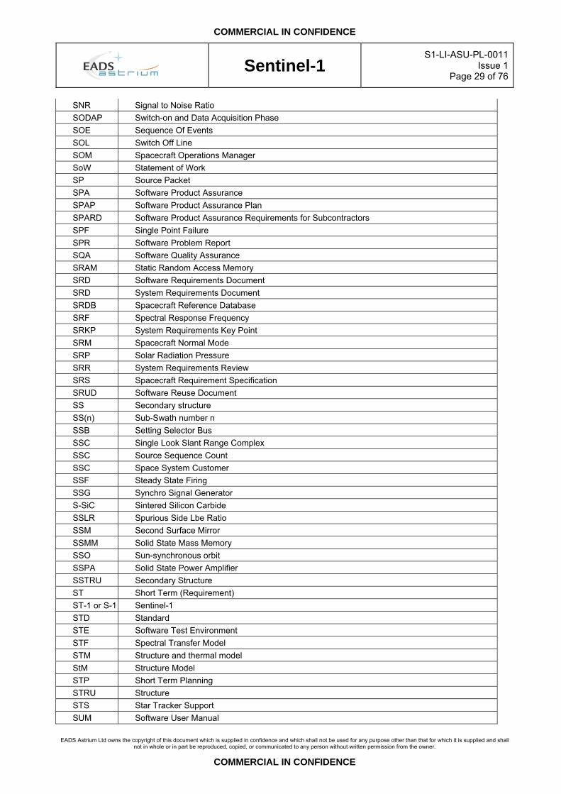
SNR Signal to Noise Ratio SODAP Switch-on and Data Acquisition Phase SOE Sequence Of Events SOL Switch Off Line SOM Spacecraft Operations Manager SoW Statement of Work SP Source Packet SPA Software Product Assurance SPAP Software Product Assurance Plan SPARD Software Product Assurance Requirements for Subcontractors SPF Single Point Failure SPR Software Problem Report SQA Software Quality Assurance SRAM Static Random Access Memory SRD Software Requirements Document SRD System Requirements Document SRDB Spacecraft Reference Database SRF Spectral Response Frequency SRKP System Requirements Key Point SRM Spacecraft Normal Mode SRP Solar Radiation Pressure SRR System Requirements Review SRS Spacecraft Requirement Specification SRUD Software Reuse Document SS Secondary structure SS(n) Sub-Swath number n SSB Setting Selector Bus SSC Single Look Slant Range Complex SSC Source Sequence Count SSC Space System Customer SSF Steady State Firing SSG Synchro Signal Generator S-SiC Sintered Silicon Carbide SSLR Spurious Side Lbe Ratio SSM Second Surface Mirror SSMM Solid State Mass Memory SSO Sun-synchronous orbit SSPA Solid State Power Amplifier SSTRU Secondary Structure ST Short Term (Requirement) ST-1 or S-1 Sentinel-1 STD Standard STE Software Test Environment STF Spectral Transfer Model STM Structure and thermal model StM Structure Model STP Short Term Planning STRU Structure STS Star Tracker Support SUM Software User Manual

COMMERCIAL IN CONFIDENCE
Sentinel-1
S1-LI-ASU-PL-0011Issue 1
Page 30 of 76
EADS Astrium Ltd owns the copyright of this document which is supplied in confidence and which shall not be used for any purpose other than that for which it is supplied and shall
not in whole or in part be reproduced, copied, or communicated to any person without written permission from the owner.
COMMERCIAL IN CONFIDENCE
SUTP Software Unit Test Plan SUTR Software Unit Test Reports SVC Service Call SVF SAR Verification Facility SVF Software Verification Facility SVT System Validation Test SVVP Software Verification and Validation Plan SW or S/W Software SWL Sampling Window Length SWST Sampling Window Start Time Sync Synchronisation
T T Test T/R Transmit/Receive TAP Telemetry Acquisition Processor TAP Test Access Port TAR Tape Archiver – Unix file format TAT Trans Atlantic Terrestrial Cable TB Thermal Balance TB/TV Thermal Balance/Thermal Vacuum TBA To Be Agreed TBC To Be Confirmed TBD To Be Defined TBI To Be Issued or To Be Included TBS To Be Specified TByte Terabyte TC Telecommand TC Terminal Count TC/TF Telecommand Transfer Frame TCA Test Connector Active TCA Thrust Chamber Assembly TCC Telecommand Clock TCM Timing Control Module TCP Transfer Control Protocol TCS Telecommand Stream TCS Thermal Control Subsystem TCSEH Thermal Electrical Hardware Set TCU Tile Control Unit TDM Time Division Multiplexed TDS Telemetry Data Stream TE Test Equipment TEC Thermo-Electrical Cooler (Peltier cooler) TEC Total Electron Count TEC Transmit Error Count TEL TELescope Temp
Comp Temperature Compensation
TF Transfer Frame according to CCSDS TFD Total Fixed Delay TFG Transfer Frame Generator

COMMERCIAL IN CONFIDENCE
Sentinel-1
S1-LI-ASU-PL-0011Issue 1
Page 31 of 76
EADS Astrium Ltd owns the copyright of this document which is supplied in confidence and which shall not be used for any purpose other than that for which it is supplied and shall
not in whole or in part be reproduced, copied, or communicated to any person without written permission from the owner.
COMMERCIAL IN CONFIDENCE
TFOV Total Field-Of-View TFT Thin Film Transistor TG Trajectory Generator TGU Transmit Gain Unit TH THermistor TICD Thermal Interface Control Document TID Total Ionising Dose TIF Transponder Interface TLE Two Line Elements TLM Telemetry TM Telemetry TMC Period of Master Clock TMDD Telemetry Deformatter and Decryptor TMFE Telemetry Formatter and Encryptor TML Total Mass Loss TMM Thermal Mathematical Model TMTC Telemetry-TeleCommand TMTF Telemetry Transfer Frame TN Technical Note TOPAS Technology Development for On-Board SAR-Processor and Storage Demonstrator TOPS Terrain Observation Progressive Scanning TPL Transmit Pulse Length TQD Telemetry Query Display TR Transmit/Receive TRB Test Review Board TREF Reference Temperature TRF Spacecraft Transfer Mode TRK Tracking TRM Transmit-Receive Module TRP Temperature Reference Point TRP Temperature Reference Point TRR Test Readiness Review TS Technical Specification TSP Twisted Shielded Pair TSR TerraSAR TSX TerraSAR-X TT&C Telemetry, Tracking & Control (/Command) TTAG Time Tag (command) TTL Transistor Transistor Logic TTR Telemetry Telecommand and Reconfiguration TV Thermal Vacuum TVD Total Variable Delay TWTA Travelling Wave Tube Amplifier Tx Transmit(ter) TxA Transmitter Assembly TXD Transmit Data Tx-H Transmit mode for horizontal polarisation TxM Transmit module Tx-V Transmit mode for vertical polarisation
U
COMMERCIAL IN CONFIDENCE
Sentinel-1
S1-LI-ASU-PL-0011Issue 1
Page 32 of 76
EADS Astrium Ltd owns the copyright of this document which is supplied in confidence and which shall not be used for any purpose other than that for which it is supplied and shall
not in whole or in part be reproduced, copied, or communicated to any person without written permission from the owner.
COMMERCIAL IN CONFIDENCE
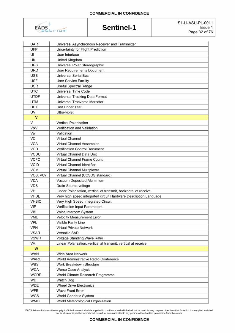
UART Universal Asynchronous Receiver and Transmitter UFP Uncertainty for Flight Prediction UI User Interface UK United Kingdom UPS Universal Polar Stereographic URD User Requirements Document USB Universal Serial Bus USF User Service Facility USR Useful Spectral Range UTC Universal Time Code UTDF Universal Tracking Data Format UTM Universal Tranverse Mercator UUT Unit Under Test UV Ultra-violet
V V Vertical Polarization V&V Verification and Validation Val Validation VC Virtual Channel VCA Virtual Channel Assembler VCD Verification Control Document VCDU Virtual Channel Data Unit VCFC Virtual Channel Frame Count VCID Virtual Channel Identifier VCM Virtual Channel Multiplexer VCS, VC7 Virtual Channel (CCSDS standard) VDA Vacuum Deposited Aluminium VDS Drain-Source voltage VH Linear Polarisation, vertical at transmit, horizontal at receive VHDL Very high speed integrated circuit Hardware Description Language VHSIC Very High Speed Integrated Circuit VIP Verification Input Parameters VIS Voice Intercom System VME Velocity Measurement Error VPL Visible Panty Line VPN Virtual Private Network VSAR Versatile SAR VSWR Voltage Standing Wave Ratio VV Linear Polarisation, vertical at transmit, vertical at receive
W WAN Wide Area Network WARC World Administrative Radio Conference WBS Work Breakdown Structure WCA Worse Case Analysis WCRP World Climate Research Programme WD Watch Dog WDE Wheel Drive Electronics WFE Wave Front Error WGS World Geodetic System WMO World Meteorological Organisation

COMMERCIAL IN CONFIDENCE
Sentinel-1
S1-LI-ASU-PL-0011Issue 1
Page 33 of 76
EADS Astrium Ltd owns the copyright of this document which is supplied in confidence and which shall not be used for any purpose other than that for which it is supplied and shall
not in whole or in part be reproduced, copied, or communicated to any person without written permission from the owner.
COMMERCIAL IN CONFIDENCE
WP Work Package WPD Work Package Description WRS World Reference System WS Workstation WWW Word Wide Web
X XCAL External Calibration XDA X-Band Downlink Assembly XFE X-Band Front End XML eXtensible Markup Language XO Crystal Oscillator
Y YPM Yaw Pointing Mode

COMMERCIAL IN CONFIDENCE
Sentinel-1
S1-LI-ASU-PL-0011Issue 1
Page 34 of 76
EADS Astrium Ltd owns the copyright of this document which is supplied in confidence and which shall not be used for any purpose other than that for which it is supplied and shall
not in whole or in part be reproduced, copied, or communicated to any person without written permission from the owner.
COMMERCIAL IN CONFIDENCE
4. DEFINITIONS
4.1 System
Constants and Units
Measurement units are defined in the SI system.
Sentinel-1 System
The end-to-end space and ground segment infrastructure that acquires, generates and delivers both single (C-band) space-borne SAR basic products (Level 1B).
Sentinel-1 Spacecraft
The C-band spacecraft component of the Sentinel-1 System, comprising the Sentinel-1 Payload supported by the Sentinel-1 Platform, together with the spacecraft-level functions structure, thermal, propulsion, and spacecraft mechanisms.
Sentinel-1 Platform
The platform component of the Spacecraft, providing the typical electrical platform functions only, i.e. attitude determination and control, navigation (GNSS), power generation distribution and storage, spacecraft-level FDIR and software, telemetry tracking & control (TT&C) and measurement data link functions provided by the bus.
Sentinel-1 Payload
The payload component of the Spacecraft, providing the C-band SAR instrument.
Sentinel-1 Launcher
The launch vehicle required for delivery of the Sentinel-1 Spacecraft to its nominal orbit.
Sentinel-1 Ground Segment
The ground segment infrastructure component of the Sentinel-1 System, comprising control, reception and processing facilities capable of generating basic products (Level 1B).
Order to Acquisition Time
Time, from placing an order, to create a data product centred at an arbitrary location to the next possible acquisition of the raw radar signal data by the satellite. As an order can be placed at any time in the orbit cycle the appropriate values for 5% probability of compliance and for 95% probability of compliance are specified when the product location is arbitrarily selected within the requested access area. In all cases where two access or processing times are identified, the less demanding one is associated with 95% of required data-sets and the more demanding one with 5%.
Revisit Time
The Revisit Time is the time between two consecutive possible observations of the same target in the full performance incidence angle range at a particular latitude. 95% revisit time is the 95 percentile of the revisit time of all points at the specified latitude (or at equator if not explicitly specified).

COMMERCIAL IN CONFIDENCE
Sentinel-1
S1-LI-ASU-PL-0011Issue 1
Page 35 of 76
EADS Astrium Ltd owns the copyright of this document which is supplied in confidence and which shall not be used for any purpose other than that for which it is supplied and shall
not in whole or in part be reproduced, copied, or communicated to any person without written permission from the owner.
COMMERCIAL IN CONFIDENCE
Quality of Service
A mechanism to provide to the user a statement of the expected performance of the system in terms of accuracy, timeliness and completeness.

COMMERCIAL IN CONFIDENCE
Sentinel-1
S1-LI-ASU-PL-0011Issue 1
Page 36 of 76
EADS Astrium Ltd owns the copyright of this document which is supplied in confidence and which shall not be used for any purpose other than that for which it is supplied and shall
not in whole or in part be reproduced, copied, or communicated to any person without written permission from the owner.
COMMERCIAL IN CONFIDENCE
4.2 C-SAR Instrument This section lists instrument definitions and SAR terms, many of which are taken from IRD01 - System Requirements Document.
Across track direction
The across track direction is defined as normal to the along track direction in the tangent plane at the geodetic sub-satellite position.
Along track direction
The along track direction is parallel to the projection of the Spacecraft velocity on the tangent plane to the Earth at the geodetic sub-satellite position.
Ambiguity Ratio
The unambiguous zone is defined in the across-track direction by the nominal swath width and in the along-track direction by the total processed Doppler bandwidth. The ambiguous zone is outside this area. Calibration Calibration is the procedure for converting the instrument measurement output data into the required physical units. After calibration, the output data must be within a known tolerance, consistent with all performance requirements, everywhere across the swath, around the orbit, over the dynamic range and over the lifetime of the instrument. Calibration is based on characterisation measurements performed on-ground before launch and in-flight. Characterisation Characterisation is the direct measurement, or analytical derivation from measurement, of a set of technical and functional parameters, over a range of conditions (e.g. temperature) to provide data necessary for calibration, ground processor initialisation and verification. Characterisation can be performed either before launch on-ground or in-flight. In-flight, at least all those parameters have to be determined that may have varied since on-ground characterisation or which have not been measurable on-ground. In-flight characterisation may be based either on data derived from facilities built into the instrument (internal calibration) and/or on external sources (external calibration).
Chirp Slope
This defines the Chirp frequency versus time response which must be achieved over the Resolution Bandwidth (see later entry).
Cross-polar Isolation
• Vertical polarisation is defined as that electric field having the peak component Ev of the electric field vector in a plane containing the satellite local vertical and the direction of propagation.
• Horizontal polarisation is defined as that electric field having the peak component Eh of the electric field vector in a plane orthogonal to this one and also containing the direction of propagation
If the system operates in vertical polarisation and assuming no polarisation rotation due to atmospheric or scattering effects, the cross polar isolation in transmission is defined as
⎟⎟⎠
⎞⎜⎜⎝
⎛= Tx
h
Txv
EEX 10log20

COMMERCIAL IN CONFIDENCE
Sentinel-1
S1-LI-ASU-PL-0011Issue 1
Page 37 of 76
EADS Astrium Ltd owns the copyright of this document which is supplied in confidence and which shall not be used for any purpose other than that for which it is supplied and shall
not in whole or in part be reproduced, copied, or communicated to any person without written permission from the owner.
COMMERCIAL IN CONFIDENCE
where: TxvE is the vertical peak component of the electric field vector at transmit and TxhE is the corresponding horizontal peak component of the electric field vector
Similarly the power ratio of vertical to horizontal channel which results from receiving an ideal plane wave polarised in horizontal direction (in target coordinate system) is denoted cross polar isolation in receive. When only a single value is specified it shall apply to receive and to transmit separately.
C-SAR Electronics Subsystem (SES)
The back end electronics component of the C-SAR Instrument, providing the radar control, IF/RF signal generation and receive data handling functions.
C-SAR Data Link
The on-board data handling and down-linking component of the Platform, providing measurement data
C-SAR Antenna Subsystem (SAS)
The active and passive antenna components of the C-SAR Instrument, providing the high power generation, signal detection, and beam-forming, radiating and calibration functions.
C-SAR Instrument
The C-band SAR Instrument component of the Sentinel-1 Payload, providing the SES and SAS radar front end and control electronics functions, and interface to mass storage and X-band down-linking functions.
C-SAR Tile
The repeatable, modular assemblies of the SAS that together constitute the active antenna components of the SAS. The C-SAR Tiles also provide partial structural support to the antenna (the rest being provided by the Payload Panel, the other structural component of the C-SAR Front End).
Data Collection Angle Range
Range of incidence angles for which basic products may be acquired albeit with relaxed performance.
Distributed Target Ambiguity Ratio (DTAR)
The distributed target ambiguity ratio is the ratio of energy contribution from a distributed target in the ambiguous zones to the energy contribution from a distributed target located in the unambiguous zone. The ratio is to be calculated using the Distributed Target Radar Cross Section Reference Model and it is specified as the ratio P’T/ΣPA, where:
• P’T is the intensity of the radar response to a distributed target located within the unambiguous zone
• ΣPA is the summed intensity of the radar responses to the respective distributed targets within the various ambiguous zones
Distributed Target Radar Cross-section Reference Model The value represents a mean level, and allows clear separation of dynamic range and the contributions of point-target ambiguities in subsequent interpretation. The best-estimate radar cross-section model shall be agreed and then become part of this document. Dynamic Range Distributed Target The dynamic range for distributed targets is defined as the range of 0σ values (extending from min,0σ to
max,0σ ) of a uniform distributed target within each full performance swath over which the performance requirements are met.

COMMERCIAL IN CONFIDENCE
Sentinel-1
S1-LI-ASU-PL-0011Issue 1
Page 38 of 76
EADS Astrium Ltd owns the copyright of this document which is supplied in confidence and which shall not be used for any purpose other than that for which it is supplied and shall
not in whole or in part be reproduced, copied, or communicated to any person without written permission from the owner.
COMMERCIAL IN CONFIDENCE
Dynamic Range Point Targets The dynamic range of a for point target is defined as the dB ratio between the greatest power to be recorded in a basic image product and the lowest local mean noise power in that image (noise levels may be variable and hence the lowest is identified).
Equivalent Number of Looks (ENL)
The equivalent number of looks over a uniform region of imagery is calculated as:
2r
2
2
q
1ENL =σ
µ=
Full Performance Angle Range
Range of incidence angles over which basic products are required to meet all data quality parameters.
Impulse Response Function (IRF)
The impulse response function (IRF) is defined as the two dimensional response in the detected image to a point target located in the product coverage area, neglecting effects of background clutter and thermal noise.
Integrated Side-lobe Ratio (ISLR)
The ratio of energy within the main lobe of the IRF (defined as lying within a rectangle of size 2x and 2y centred on the peak, where x and y are the 3dB widths in range and azimuth) and the energy outside of this area integrated over a region bounded by sides 10 times longer. Inter-channel Phase Accuracy Inter-channel phase accuracy is defined as the 3σ phase error between any pair of elements of the Scattering matrix of a polarimetric product. Inter-channel Radiometric Accuracy Inter-channel radiometric accuracy is defined as the maximum rms error of the power of any element of the Scattering matrix of a polarimetric product normalised to the mean power of the largest element in the Scattering matrix.
Looks (Range, Azimuth)
Number of statistically independent looks accumulated in the respective direction during product generation.
Minimum Swath Overlap
For strip map products the image area is selectable from pre-defined swathes. Swath flexibility defines the overlap of adjacent selectable swathes in terms of percentage of swath width. The swath width is at least as large as the product coverage in across track direction.
Natural Azimuth Looks
In ScanSAR operation the azimuth integration time is split and the different beams are scanned in a pre-defined cycle. The number of natural looks corresponds to the number of scan cycles within a complete synthetic aperture. With increasing number of natural looks the burst duration and bandwidth decreases.
Noise Equivalent Sigma Nought (NESZ)
The NESZ is defined as the back-scatter coefficient σ0 (back-scattering cross section of a distributed target per unit area) of a distributed target within the product coverage for which the signal power level in the final image is equal to the noise power level (thermal noise plus quantisation noise), i.e., an image SNR of 0 dB.

COMMERCIAL IN CONFIDENCE
Sentinel-1
S1-LI-ASU-PL-0011Issue 1
Page 39 of 76
EADS Astrium Ltd owns the copyright of this document which is supplied in confidence and which shall not be used for any purpose other than that for which it is supplied and shall
not in whole or in part be reproduced, copied, or communicated to any person without written permission from the owner.
COMMERCIAL IN CONFIDENCE
Peak Side-Lobe Ratio (PSLR)
The peak side-lobe ratio is defined as the ratio of the peak intensity of the main lobe of the impulse response function (IRF) to the peak intensity of the most intense side-lobe inside a rectangular image area of 10x in the along-track and 10y in the across-track direction. x and y are the along-track and across-track resolutions in meters, respectively. In the event that the first side-lobe of the error free response is masked by the main lobe of the error included response (i.e. there is no minimum between the peak of the IRF and the first side-lobe position), then the intensity at the position corresponding to the first side-lobe in the error free case shall be used for peak side-lobe ratio determination.
Pixel Localisation Accuracy
The pixel localisation accuracy is specified as the standard deviation in the estimate of the position of a point target of sufficiently large cross-section, the estimate being the point equidistant between the –3 dB points of its detected impulse response measured in along-track and across-track directions. If the localisation error depends on location within the image (product coverage), the worst-case location is applicable. The pixel localisation accuracy refers to the system dependent accuracy therefore perfect knowledge and arbitrary dense sampling of target altitude and perfect knowledge of needed tie points need to be assumed.
Point Target Ambiguity Ratio (PTAR)
The point target ambiguity ratio is specified as the ratio PT/PA, where: • PT is the peak intensity of the radar response to a point target located within the unambiguous
zone • PA is the peak intensity of the radar response to a point target of the same radar cross section
as defined for PT but located within the worst ambiguous zone
Polarisation Modes
• Quad-pol: Quad-polarisation mode, operated with fully-interleaved pulse transmission and dual-channel reception (HH+HV+VH+VV)
• Dual-pol: Dual-polarisation mode, operated with selectable single-pol transmission and dual-channel reception (i.e. generating HH+HV or VV+VH)
• Single Polarisation: Transmission and reception in a) a single linear polarisation (HH or VV) or b) cross-polar polarisation (HV or VH)
Product coverage
Size of a Basic Product in terms of along-track * across-track extension. Swath width is the across track ground range which is imaged and over which the
performance requirements have to be predicted and verified. Swath length is the along track distance which is imaged and over which the
performance requirements have to be predicted and verified.
Product Location Accuracy
Product coverage location accuracy is defined as the maximum difference between the locations of the area specified in an acquisition order and that of the SAR image actually acquired. In other words, the product coverage location accuracy defines the maximum allowable deviation of the location of a recorded scene from the specified one.

COMMERCIAL IN CONFIDENCE
Sentinel-1
S1-LI-ASU-PL-0011Issue 1
Page 40 of 76
EADS Astrium Ltd owns the copyright of this document which is supplied in confidence and which shall not be used for any purpose other than that for which it is supplied and shall
not in whole or in part be reproduced, copied, or communicated to any person without written permission from the owner.
COMMERCIAL IN CONFIDENCE
Radiometric Accuracy
For a distributed target, the radiometric accuracy is defined as the worst-case uncertainty resulting from measurement of 0σ of an uniform invariant distributed target situated anywhere in the operating dynamic range of the system, anywhere in the swath and anywhere in the orbit assuming that the standard deviation of the estimate of 0σ associated with each measurement is zero (ignoring speckle). For a point target, the radiometric accuracy is defined as the worst-case 3 uncertainty resulting from measurement of the radar cross section, pσ , of a point target which lies in the range:
2min0 75 mdByx p ⋅<<⋅⋅ σσ
where:
• min0σ is the value of NESZ at the bottom end of the specific dynamic range • yx ⋅ are the measured spatial resolutions in the along track and across track directions
respectively
The point target may be located anywhere within the swath at any point within the orbit. The determination of absolute back-scattering values will in general involve calibration measurements over characterised reference targets to be referred to as external calibration. Two parameters are used in defining the radiometric accuracy:
The worst-case errors due to all causes which produce errors that are invariant or vary slowly with respect to the orbit,
The worst-case errors due to all causes, both those in a) and those that are independent from measurement to measurement of the target (e.g. due to different position within the swath).
Changing propagation path characteristics shall be accounted for by assuming uncertainty concerning the presence or absence of rain. The required parameter for radiometric accuracy shall relate to parameter b) above. Parameter a) shall however be supplied for information.
Radiometric Resolution
The radiometric resolution of a Level 1 product is a measure of the ability to distinguish between uniform distributed targets with different backscattering coefficient. It is defined as the width of the probability distribution function of the signal power received from uniform distributed targets. It is measured on a uniform distributed target, large enough to ensure statistical accuracy, as:
Where: µ , σ and qr are respectively the mean, the standard deviation and the normalised standard
deviation (or coefficient of variation) of signal power over the selected distributed target.
Radiometric Stability
Radiometric stability is defined as the standard deviation of a data set that results from measuring the radar cross section of an invariant target, at different times, being of such magnitude that receiver noise is insignificant, with the system operating within its dynamic range. Perturbations due to the propagation path shall be neglected. There shall be no limitation on the position of the target inside the swath and along the orbit. The time scale applicable for this specification is the duration planned between external calibrations. Relative Phase Error The interferometric phase is defined as the phase difference resulting from the geometric path difference when observing the same target from different positions. The relative interferometric phase error is defined as the contribution to the phase difference between two measurements of the same target from different positions that is not resulting from the geometrical path difference.
µσ
=rq)1(log10Re 10 rqsRad +=

COMMERCIAL IN CONFIDENCE
Sentinel-1
S1-LI-ASU-PL-0011Issue 1
Page 41 of 76
EADS Astrium Ltd owns the copyright of this document which is supplied in confidence and which shall not be used for any purpose other than that for which it is supplied and shall
not in whole or in part be reproduced, copied, or communicated to any person without written permission from the owner.
COMMERCIAL IN CONFIDENCE
Relative Radiometric Accuracy
Relative radiometric accuracy is defined as the standard deviation of a data set that results from measuring the radar cross section of equivalent targets at the same time at different locations within the product coverage. This includes stability effects within the time needed for the acquisition of the basic product.
Resolution Bandwidth (RBW)
This is the bandwidth over which the chirp must meet the phase and amplitude error specifications.
RF Pulsewidth
This corresponds to the 3dB bandwidth of the RF pulse. It is specified in the time domain but is related to the frequency domain due to the Chirp Slope (see entry ealier).
ScanSAR
Lower resolution, large area SAR imaging mode with several simultaneous beams and principally unlimited azimuth extent of acquisition.
Spatial resolution
The spatial resolution is specified as the width of the IRF where the intensity is 50% of the peak value. The spatial resolution is given in metres and divided into along-track and across-track resolution.
Spurious Side-lobe Ratio (SSLR)
The spurious sidelobe ratio is specified as the ratio of the peak intensity of the main lobe of IRF to the peak intensity of the most intense side-lobe outside a rectangular image area of 10x in the along-track and 10y in the across-track direction. x and y are the along-track and across-track resolutions in meters, respectively.

COMMERCIAL IN CONFIDENCE
Sentinel-1
S1-LI-ASU-PL-0011Issue 1
Page 42 of 76
EADS Astrium Ltd owns the copyright of this document which is supplied in confidence and which shall not be used for any purpose other than that for which it is supplied and shall
not in whole or in part be reproduced, copied, or communicated to any person without written permission from the owner.
COMMERCIAL IN CONFIDENCE
4.3 Spacecraft and Platform
Right-Looking
Attitude, in which the front end co-ordinate system +Zas axis is tilted 28 degrees away from nadir in anti-Sun direction (+28degrees elevation angle). See Figure 5.2-1.
Left-Looking
Attitude, in which the front end co-ordinate system +Zas axis is tilted 28 degrees away from nadir in the Sun direction (-28degrees elevation angle). See Figure 5.2-1.
Pointing Accuracy
Pointing accuracy is the deviation of the actual pointing vector from the ideal pointing vector at any instant
Instrument Line of Sight
In case of a phased array, the instrument Line of Sight is normal to the plane determined by a best-fit of the actual surface defined by the instrument antenna phase centres. In stable conditions, i.e. during ground characterisation tests, it is related to the instrument optical reference cube axes through a customer furnished transformation matrix, defined during those ground characterisation and alignment tests. Electronic internal instrument pointing knowledge and electrical stability are excluded from this definition.
Antenna Boresight
Antenna Boresight is the direction of the maximum radiation of the antenna when the aperture illumination is set to uniform gain and phase for no beam-steering (i.e. in case of a phased array all sub-arrays would be set uniformly at nominal maximum amplitude and uniform phase distribution). If mechanical distortions induced by environmental loads are negligible, the difference between Line of Sight and Antenna Boresight for a phased-array is caused solely by drift or deviation of the sub-array settings.
Instrument Mounting Interface
Instrument Mounting Interface is the interface provided by the Spacecraft to the relevant instrument and associated mounting insert patterns.
Antenna Elevation Angle
The Antenna Elevation Angle (θel) is defined as the sum of the Mechanical Boresight Elevation Angle (θΜΒel) and the Electrical Elevation Angle (θΕel), which are defined as follows:
• The Mechanical Boresight Elevation Angle θΜΒel (± 90º) is defined in the Yas * Zas plane as the angle between the negative direction of the L1 axis of the Local Relative Orbital Reference Frame (local nadir) and the +Zas axis of the Antenna Reference Frame, where positive angle is measured from the negative direction of L' (local nadir) towards the +Yas direction.
• The Electrical Elevation Angle θΕel (± 90º) is defined in the Yas * Zas plane relative to the +Zas-axis with positive values towards the +Yas-axis.

COMMERCIAL IN CONFIDENCE
Sentinel-1
S1-LI-ASU-PL-0011Issue 1
Page 43 of 76
EADS Astrium Ltd owns the copyright of this document which is supplied in confidence and which shall not be used for any purpose other than that for which it is supplied and shall
not in whole or in part be reproduced, copied, or communicated to any person without written permission from the owner.
COMMERCIAL IN CONFIDENCE
Antenna Azimuth Angle
The Antenna Azimuth Angle, Φaz (± 90º) is defined in the Xas * Zas plane as the angle between the negative direction of the L' axis of the Local Relative Orbital Reference Frame (local nadir) and the +Zas axis of the Antenna Reference Frame, where positive angle is measured from the negative direction of L1 (local nadir) towards the +Xas direction.
Total User Capacity
The total user capacity is defined as the memory space available for storage and retrieval of user data excluding the memory space used for DMSS internal error detection and error correction (EDAC based on Reed-Solomon Code).
Files
Files are a set of one ore more memory segments which are allocated to store Instrument or ancillary date sets. Each file is identified by a unique file identifier.
Instrument Data Set
The Instrument Data Set are those instrument data which are obtained from an uninterrupted operation of the SAR instrument in a single measurement mode (generally, the data for one SAR Product). An Instrument Data Set is composed of a number of ESA PSS-04 source packets. The number and length of the source packets can be different for each Instrument Data Set. The length of the source packets is variable within one Instrument Data Set. The size of an Instrument Data Set can vary between 1 and the maximum number of free Memory Segments. Free in this context means: the Memory Segments are not allocated to files.
Channel Data Access Unit (CADU)
A CADU is the protocol data unit in which Telemetry Packets are embedded for transmission through the downlink data channel.
Data Sizing Definitions
For use in memory sizing only (not RF link)
• 1kbit = 2^10 bits = 1024 bits • 1Mbit = 2^20 bits = 1024 kbits = 1048576 bits • 1Gbit = 2^30 bits = 1024 Mbits = 1048576 kbits = 1073741824 bits
Reference Orbit Repeat Cycle
The Reference Orbit Repeat Cycle is the predicted repeat cycle expected at the beginning of life of the spacecraft, used for comparison with subsequent repeat cycles in order to determine the orbital tube radius error of those cycles. It shall be agreed between the Prime Contractor and the Agency.
Orbit State Vector
The orbit state vector of the spacecraft is defined as the PVT data outputted by the GNSS receiver subsystem on-board when in its measurement mode.
During outages of the GNSS receiver e.g. when not in its measurement mode, the orbit state vector of the spacecraft is defined as the PVT data outputted by the orbit propagation function of the Navigation Estimator in the AOCS.
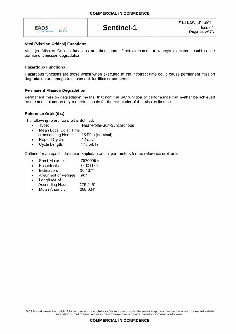
COMMERCIAL IN CONFIDENCE
Sentinel-1
S1-LI-ASU-PL-0011Issue 1
Page 44 of 76
EADS Astrium Ltd owns the copyright of this document which is supplied in confidence and which shall not be used for any purpose other than that for which it is supplied and shall
not in whole or in part be reproduced, copied, or communicated to any person without written permission from the owner.
COMMERCIAL IN CONFIDENCE
Vital (Mission Critical) Functions
Vital (or Mission Critical) functions are those that, if not executed, or wrongly executed, could cause permanent mission degradation.
Hazardous Functions
Hazardous functions are those which when executed at the incorrect time could cause permanent mission degradation or damage to equipment, facilities or personnel.
Permanent Mission Degradation
Permanent mission degradation means, that nominal S/C function or performance can neither be achieved on the nominal nor on any redundant chain for the remainder of the mission lifetime.
Reference Orbit (tbc)
The following reference orbit is defined: • Type: Near-Polar-Sun-Synchronous • Mean Local Solar Time at ascending Node: 18:00 h (nominal) • Repeat Cycle: 12 days • Cycle Length: 175 orbits
Defined for an epoch, the mean-keplerian orbital parameters for the reference orbit are:
• Semi-Major axis: 7070995 m • Eccentricity: 0.001184 • Inclination: 98.137° • Argument of Perigee: 90° • Longitude of Ascending Node: 279.248° • Mean Anomaly: 269.924°

COMMERCIAL IN CONFIDENCE
Sentinel-1
S1-LI-ASU-PL-0011Issue 1
Page 45 of 76
EADS Astrium Ltd owns the copyright of this document which is supplied in confidence and which shall not be used for any purpose other than that for which it is supplied and shall
not in whole or in part be reproduced, copied, or communicated to any person without written permission from the owner.
COMMERCIAL IN CONFIDENCE
4.4 Ground Segment
Acquisition Station
A facility for acquiring satellite data and in some cases for archiving and performing production and shipment on demand. Data can be acquired only when the satellite (or the Data Relay Satellite) is seen by the station.
Archive (near line)
Part of the archive that needs automated manipulation of media to access archived data. Near line archive is generally implemented using high-density data tape robots.
Archive (off-line)
Part of the archive that needs human manipulation of data. Off-line archive is generally implemented on high density data tapes held on shelves.
Archive (on-line)
Part of the archive that can be accessed without any human or mechanised manipulation of archive media. On-line archive is generally implemented on high capacity computer disks
Auxiliary Data
Auxiliary data are data required to perform the processing of the SAR data that are not obtained from the SAR instrument itself. Auxiliary data encompass:
• Data obtained from other parts of the platform, generally referred to as spacecraft “engineering”, “core housekeeping” or “subsystem” data: they include parameters such as on-board time, PVT vector, pressures, temperatures, etc…
• Other data not available from on-board sources
Background Mission
A set of systematically implemented payload data acquisition rules. Examples of background missions are areas to be covered during specific periods of the year, like fields during the growing season, poles during ice formation, iceberg source areas during melting periods, etc. A background mission can also be linked to the acquisition campaign of a station, particularly for mobile stations
Browse Products
• Subsets of data set other than the directory and metadata that facilitate user’s selection of specific data having the required characteristics. For example, for image data, browse data could be a single channel or multi-channel and is generally unique for each type of data. It depends on the nature of the data and on the criteria used for data selection within the related science discipline.
• Data produced primarily to provide other investigators with an understanding of the type and quality of available data. Typically, browse data sets are limited in size or resolution. The specific form of browse data depends on the type of instrument or discipline with which the browse data is related.
Calibration
Calibration is the activity of deriving correction factors to be used in ground processing to compensate for biases in the measured data. Calibration activities encompass:
• Internal Calibration • External Calibration • Geophysical Calibration

COMMERCIAL IN CONFIDENCE
Sentinel-1
S1-LI-ASU-PL-0011Issue 1
Page 46 of 76
EADS Astrium Ltd owns the copyright of this document which is supplied in confidence and which shall not be used for any purpose other than that for which it is supplied and shall
not in whole or in part be reproduced, copied, or communicated to any person without written permission from the owner.
COMMERCIAL IN CONFIDENCE
Calibration (External Calibration)
External Calibration is the derivation of correction factors through comparison with independent scales for compensation of overall system errors (within both the space and ground segments). Calibration sites on the ground are typically used for this, with either natural or man-made targets which have known parameters (e.g. location, back scatter).
Calibration (Geophysical Calibration)
Geophysical calibration involves the use of data to tune models which derive geophysical parameters e.g. wind speed, wind direction, wave height, soil moisture and atmospheric information. The extraction of these parameters from independent ground truth data and atmospheric information involves comparison with the product data and the generation of biases and scaling factors. Any detected systematic deviations are analysed and used to tune the geophysical models.
Calibration (Internal Calibration)
Internal calibration is the monitoring of functions and parameters within the instrument and the derivation of correction factors to compensate for errors of the internal equipment. The correction factors are applied as part of the ground processing.
Catalogue
A Catalogue system provides a service enabling the user to obtain detailed information about whole data sets, typically specific to a discipline, data centre or project. A catalogue also allows a user to identify and retrieve individual granules of the data set by specifying independent variable range(s). Having identified a set of granules, which may be of value, a user should be able to review a content of the granule (browse) and place an order for one or more granules. A catalogue is assumed to provide three primary services: Directory Service, Guide Service and Inventory service (see corresponding definitions)., supplemented by secondary application specific services, typically including browse and ordering.
Catalogue – Local Catalogue
A local catalogue is associated to a data set archived at a given site or centre. It reflects exactly the content of the archive to which it is associated.
Catalogue – Master Catalogue
The master catalogue is made of the sum of the catalogues held at distributed locations. It mirrors then the overall contents of the products archives within the whole ground segment. It includes in addition the catalogue of planned products, according to the actual data take schedule. The master catalogue is not directly accessible to users.
Catalogue – User Catalogue
The user catalogue is a copy of the master catalogue, from which records can be hidden to users.
Data Product
The result of the processing of remote sensing data. Products are specific to each mission and sensor combinations. A data product can be an entire acquisition strip (the data segment continuously acquired by a ground station) or a single frame (a subset of the acquisition strip of standard length as defined by the WRS).
Data Take
A data take is a continuous set of data acquired by the instrument operating in a given mode. Any change of instrument mode or e.g. incidence angle is triggering the start of a new data take.

COMMERCIAL IN CONFIDENCE
Sentinel-1
S1-LI-ASU-PL-0011Issue 1
Page 47 of 76
EADS Astrium Ltd owns the copyright of this document which is supplied in confidence and which shall not be used for any purpose other than that for which it is supplied and shall
not in whole or in part be reproduced, copied, or communicated to any person without written permission from the owner.
COMMERCIAL IN CONFIDENCE
Data Take Segment
A data take Segment (DT Segment) is a subset of a data take. A data take needs to be segmented if it cannot be dumped in a single pass over a given acquisition station.
Dissemination
Dissemination is the process allowing to distribute products and data to users. Dissemination can be made via electronic link (terrestrial or satellite based) or on physical media (CD-ROM, DVD, HDDT).
Dissemination Plan For each facility in charge of disseminating products towards end users, the dissemination plan specifies the timely organisation of dissemination operations.
Entity
Combination of facility plus respective personnel or operations organisation
Facility
Combination of ground segment elements required to perform an operational task.
Flight Operations
All activities related to the planning, execution and evaluation of the control of the space segment when in orbit.
Formatting
The conversion of the format of the products held in the PGS archives (internal format) into a format readable on the user’s computer platform (external format).
FOS
Flight Operations Segment, the facilities responsible for the spacecraft monitoring and control activities.
GMES
Global Monitoring for Environment and Security. A joint European Commission and European Space Agency initiative.
Granule
A granule is the smallest subdivision of a L1B product that can be independently ordered, processed and distributed to a user.
Ground Operations
All activities related to the planning, execution and evaluation of the control of the ground segment facility.
Ground Segment
All ground segment facilities and personnel involved in the preparation or execution of mission operations.
Ground Systems
All ground infrastructure elements that are used to support the preparation activities leading up to mission operations, the conduct of mission operations and all post-operational activities.
Instrument (data take) schedule The instrument (data take) schedule defines the timely utilisation of the on-board instrument over a given period of time, including time of sensing start and termination and specifying the sensing mode.

COMMERCIAL IN CONFIDENCE
Sentinel-1
S1-LI-ASU-PL-0011Issue 1
Page 48 of 76
EADS Astrium Ltd owns the copyright of this document which is supplied in confidence and which shall not be used for any purpose other than that for which it is supplied and shall
not in whole or in part be reproduced, copied, or communicated to any person without written permission from the owner.
COMMERCIAL IN CONFIDENCE
Inventory
Collection of items identically structured and providing values of attributes pertinent to that collection. EO inventories contain attributes like orbit/frame number, frame corner co-ordinates, acquisition time, quality, etc.
Metadata
Data about data contained in data sets, and which provide an understanding of the content and utility of the data set. Metadata may be used to select data for a particular application.
Mission
The specific function to be accomplished by a system as characterised by its expected products in terms of quantity, quality and availability.
Mission exploitation
Activity comprising the planning, utilisation and evaluation of the products of the space mission.
Mission operation
All activities related to the planning, execution and evaluation of the control of the space and ground segments during phases E and F of a space system, i.e. combination of flight and ground operations.
Mission operations data
Subset of mission information used to execute the in-orbit operations.
Mission Planning
Mission planning encompasses the whole set of activities / operations that are required to schedule the utilisation of the on-board instrument and to organise, monitor and control on the ground operations for data downlink, generation of products and their dissemination to the users.
Mission products
Products and services delivered by the space segment as the result of its in-orbit exploitation, e.g. science data.
MPS
Mission Planning and Scheduling. Includes all activities relating to the processing of planning input and planning requests, the resolution of planning conflicts and the planning of on-board and ground resources utilisation. It also includes the preparation of plans, schedules or timelines of operations as a result of the planning exercise.
NRT Processing
Near Real Time (NRT) Processing infers that processing of the mission products and their delivery to the requesting users occurs within a short time from sensing. In the Sentinel-1 case, the requirement is to acquire, process and deliver within 3 hours from sensing.
Off-line processing
Off-line processing refers to the non systematic (on-demand) processing of archived products to serve specific users requests

COMMERCIAL IN CONFIDENCE
Sentinel-1
S1-LI-ASU-PL-0011Issue 1
Page 49 of 76
EADS Astrium Ltd owns the copyright of this document which is supplied in confidence and which shall not be used for any purpose other than that for which it is supplied and shall
not in whole or in part be reproduced, copied, or communicated to any person without written permission from the owner.
COMMERCIAL IN CONFIDENCE
Orbit Data (Precise)
Precise orbit data are highly accurate orbit data derived from GNSS raw data acquired on board (pseudo range data). They are used for accurate geo-referencing of products.
Orbit Data (Predicted)
The predicted orbit data provides the forecast of the spacecraft orbit vector (position and velocity) as a function of time, over a given period (ephemeris file)
Orbit Data (Restituted)
The restituted orbit provides the actual spacecraft orbit vector (position and velocity) as a function of time, as derived from the GNSS measurements performed on-board, or from specific orbit determination sessions (using for instance range Doppler measurements)
Order
Direction issued by a user to the PGS for the provision of one or several products or services, for which the customer will accept the charge if appropriate.
Order – Complex Order
Highest level of the orders placed by users that can eventually trigger the delivery of a large number of products over an extended period of time.
Order – Coverage Order
A coverage order is made of a set of basic products sensed at a time as close as possible to a user specified date that covers the whole area selected by the user (so that a mosaic product over the whole region of interest can be created). For a coverage order the user does not need to select the individual products that populate the order, instead the system will do the job for him.
Order – Emergency Order
An emergency order is an order which requires to generate and uplink a data take request in short notice, outside the nominal mission planning cycle.
Order – Joint Order
A joint order is made of a Sentinel-1 product and a product from one of the companion missions, covering the same geographical area and for which the time of sensing difference does not exceed a user specified time span.
Order – Mission Order
Mission-Orders are generally long-term, systematic orders for new acquisitions directly introduced in the system by the Mission Operator. The objective of mission orders is to ensure that key areas of interest are adequately covered based on the needs of selected driving applications.
Order – Order Line
The order line results from the decomposition of a complex order into single orders, each of them triggering the delivery of one single product.

COMMERCIAL IN CONFIDENCE
Sentinel-1
S1-LI-ASU-PL-0011Issue 1
Page 50 of 76
EADS Astrium Ltd owns the copyright of this document which is supplied in confidence and which shall not be used for any purpose other than that for which it is supplied and shall
not in whole or in part be reproduced, copied, or communicated to any person without written permission from the owner.
COMMERCIAL IN CONFIDENCE
Order – Near Real Time (NRT) Order
An order entailing downlink, processing and product delivery to the requesting users within less than 3 hours (TBC) from sensing.
Order – Single Order
A single order is an order that triggers the delivery of one single basic product to the user requesting that order. The product can either be generated from the archive or require a new acquisition.
Order – Standing Order
A standing order (or time series order) is made of a temporal (time series) set of basic products covering a user specified region of interest over a given period of time at a user specified frequency (e.g. regular acquisition – processing – delivery of data for a period of 6 months each week). In the case of a standing order, the user may specify his/her ROI, the time span of the order and the minimum/maximum frequency of acquisition / delivery..
Order – Subscription (from archive) Order
A subscription orders is a mechanism allowing a user to request the systematic delivery of products from the archive over a given ROI and a given time period, whenever these products become available.
Order – Time Series Order
Same as “Standing Order”
Order to Acquisition Time
Time, from placing an order, to create a data product centred at an arbitrary location to the next possible acquisition of the raw radar signal data by the satellite. As an order can be placed at any time in the orbit cycle the appropriate values for 5% probability of compliance and for 95% probability of compliance are specified when the product location is arbitrarily selected within the requested access area. In all cases where two access or processing times are identified, the less demanding one is associated with 95% of required data-sets and the more demanding one with 5%.
Payload Ground Segment
The facilities responsible for the acquisition, archiving, processing and dissemination of the instrument data and basic products.
Pointing Data
Pointing data encompass the whole set of data required by a receiving station to point its antenna towards the anticipated location of the satellite above the horizon. They consist generally in AOS/LOS times and Two Line Elements (TLE) files providing azimuth and elevation data as a function of time.
Priority
Different priority levels are attached to users orders and to the requests resulting from their decomposition. These priority levels are used to establish the instrument data take schedule and to schedule the downlink, processing and dissemination operations on ground according to the available resources.

COMMERCIAL IN CONFIDENCE
Sentinel-1
S1-LI-ASU-PL-0011Issue 1
Page 51 of 76
EADS Astrium Ltd owns the copyright of this document which is supplied in confidence and which shall not be used for any purpose other than that for which it is supplied and shall
not in whole or in part be reproduced, copied, or communicated to any person without written permission from the owner.
COMMERCIAL IN CONFIDENCE
Production Plan
For each facility in charge of products generation, the production plan specifies the timely organisation of products generation activities.
Raw Data
The data received on ground from the satellite prior to the application of any processing algorithm
Region Of Interest (ROI)
Geographic area relevant for the process. In its more general form it can be defined for example as one or more (or a combination of):
• rectangle (usually with sides aligned with the latitude / longitude grid) • circle • polygon • name (of a site, a region, a country, a town, a river, etc., or of multiple sites together, like volcanoes)
Replay
A Replay is a unit of data comprising one or several Data Takes or a Data Take Segment downlinked to a Ground Station during one ground contact period. (TBC).
Replay Key
A Replay Key (RK) is a decryption key linked to a given replay.
Request
A request is the lowest level of decomposition of an order. Four types of requests are defined within the system:
• Data take requests, which relate to the continuous sensing of a given area by the on-board sensor operating in a given mode
• Downlink requests which relate to the downlink of a data take segment towards a given receiving station
• Processing requests which relate to the generation of a Level 1B product from newly acquired or archived Level 0 data
• Dissemination requests which relate to the delivery to a user of a product after it has been processed
Requests Data Base
The Requests Data Base contains all users’ orders and their lower level decomposition into order lines and requests. It is the reference for the PGS operators to establish the instrument data take schedule and mission plan, and for the users to be kept informed about the status of their orders.
Routine processing
Routine processing refers to the daily systematic processing of all data received within a given time frame.

COMMERCIAL IN CONFIDENCE
Sentinel-1
S1-LI-ASU-PL-0011Issue 1
Page 52 of 76
EADS Astrium Ltd owns the copyright of this document which is supplied in confidence and which shall not be used for any purpose other than that for which it is supplied and shall
not in whole or in part be reproduced, copied, or communicated to any person without written permission from the owner.
COMMERCIAL IN CONFIDENCE
4.5 Lifetime Spacecraft Beginning-of-Life
The point at which spacecraft in-orbit commissioning activity ceases and the spacecraft useful lifetime (payload imaging operations) begins.
Spacecraft End-of-Life
The time at which the Spacecraft-specific (i.e. not System-level) operational performance (imaging) ceases to be compliant with Customer End-of-Life (EOL) requirements, or the time at which the specified duration for which the spacecraft operational performance (imaging) requirements are valid elapses, whichever is sooner.
Spacecraft Useful Lifetime
The Spacecraft Useful Lifetime is defined as the duration from the end of the Spacecraft Commissioning Phase, i.e. Spacecraft BOL, to the end of the useful payload operations, i.e. Spacecraft EOL.
In-Orbit Payload Design Lifetime
Total in-orbit duration of Spacecraft from Launch to Spacecraft End-of-Life.
In-Orbit Platform Design Lifetime
Total in-orbit duration of Spacecraft from Launch to the end of the controlled decommissioning orbital manoeuvre activities
System End-of-Life
The time at which the System-level (i.e. not Spacecraft-level) operational performance (imaging) ceases to be compliant with Customer End-of-Life (EOL) requirements, or the time at which the specified duration for which the system operational performance (imaging) requirements are valid elapses, whichever is sooner. System Lifetime (Mission Lifetime) The System Lifetime is defined as the duration from the end of the System Commissioning Phase to System EOL. The relationship between the above lifetime definitions is shown figuratively in Figure 4.5-1 below.

COMMERCIAL IN CONFIDENCE
Sentinel-1
S1-LI-ASU-PL-0011Issue 1
Page 53 of 76
EADS Astrium Ltd owns the copyright of this document which is supplied in confidence and which shall not be used for any purpose other than that for which it is supplied and shall
not in whole or in part be reproduced, copied, or communicated to any person without written permission from the owner.
COMMERCIAL IN CONFIDENCE
TerraSAR-L S/C Development and Integration Phase
TerraSAR-L S/C Launch and Early
Orbit Phase
Commissioning Phase
System Operational
Phase
Disposal Phase
System Lifetime
TerraSAR-L S/C
Launch
De-orbit manoeuvres Re-entry
S/C Useful Lifetime
G/S available
S/C
Com
mis
sion
ing
Pha
se
Sys
tem
C
omm
issi
onin
g P
hase
S/C End of Life
In-Orbit Payload Design Lifetime
S/C Beginning of Life
In-Orbit Platform Design Lifetime
Figure 4.5-1: Relationship of Lifetime Definitions to Mission Phases

COMMERCIAL IN CONFIDENCE
Sentinel-1
S1-LI-ASU-PL-0011Issue 1
Page 54 of 76
EADS Astrium Ltd owns the copyright of this document which is supplied in confidence and which shall not be used for any purpose other than that for which it is supplied and shall
not in whole or in part be reproduced, copied, or communicated to any person without written permission from the owner.
COMMERCIAL IN CONFIDENCE
5. BACKSCATTERING MODEL
5.1 Terrain The backscattering model to be used for terrain is the Short Vegetation Model based in F. T. Ulaby and M. C. Dobson. It is shown in dB in Table 4.1-1 and Figure 4.1-1, for the three polarisations (HH, HV and VV) and the incidence angles from 20° to 45°.
Inc angle 20 25 30 35 40 45HH -7.61 -9.07 -10.31 -11.32 -12.17 -12.86HV -15.59 -16.33 -16.95 -17.47 -17.90 -18.29VV -7.64 -8.98 -10.05 -10.92 -11.61 -12.19
Table 5.1-1 Backscattering coefficient of terrain
C-band sigma0 for terrain
-20.00
-15.00
-10.00
-5.00
0.0020 25 30 35 40
Incidence Angle
Sigm
a0 (d
B)
HHHVVV
Figure 5.1-1 Backscatering coefficient of terrain
5.2 Ocean For Ocean, the backscattering model to be used is shown in the following Table 5.2-1 and in Figure 5.2-1 and Figure 5.2-2.
HH 2 m/s 4 m/s 6 m/s 8 m/s 10 m/s 12 m/s 14 m/s20 deg -2.49 -0.41 0.75 1.54 2.13 2.60 2.9930 deg -15.53 -11.79 -9.68 -8.21 -7.09 -6.19 -5.4445 deg -27.77 -23.54 -21.06 -19.29 -17.92 -16.79 -15.84VV20 deg -1.44 0.38 1.40 2.10 2.64 3.09 3.4830 deg -13.46 -9.42 -7.11 -5.51 -4.29 -3.31 -2.4945 deg -22.99 -18.29 -15.59 -13.70 -12.26 -11.08 -10.09
Table 5.2-1 Ocean Backscattering Model for C Band (5.3 GHz)

COMMERCIAL IN CONFIDENCE
Sentinel-1
S1-LI-ASU-PL-0011Issue 1
Page 55 of 76
EADS Astrium Ltd owns the copyright of this document which is supplied in confidence and which shall not be used for any purpose other than that for which it is supplied and shall
not in whole or in part be reproduced, copied, or communicated to any person without written permission from the owner.
COMMERCIAL IN CONFIDENCE
Ocean Backscattering (HH)
-30.00
-25.00
-20.00
-15.00
-10.00
-5.00
0.00
5.00
20 25 30 35 40 45
Incidence Angle (deg)
Ave
rage
NR
CS
(deg
) 2 m/s4 m/s6 m/s8 m/s10 m/s12 m/s14 m/s
Figure 5.2-1 Ocean Backscattering for C band (5.3 GHz) in HH polarisation
Ocean Backscattering (VV)
-25.00
-20.00
-15.00
-10.00
-5.00
0.00
5.00
20 25 30 35 40 45
Incidence Angle (deg)
Ave
rage
NR
CS
(dB
) 2 m/s4 m/s6 m/s8 m/s10 m/s12 m/s14 m/s
Figure 5.2-2 Ocean Backscattering for C band (5.3 GHz) in VV polarisation]

COMMERCIAL IN CONFIDENCE
Sentinel-1
S1-LI-ASU-PL-0011Issue 1
Page 56 of 76
EADS Astrium Ltd owns the copyright of this document which is supplied in confidence and which shall not be used for any purpose other than that for which it is supplied and shall
not in whole or in part be reproduced, copied, or communicated to any person without written permission from the owner.
COMMERCIAL IN CONFIDENCE
6. REFERENCE FRAMES These have been developed from ESA SRD Annex B. Further definition may be found in the AOCS Reference Frames Technical Note (to be issued).
INERTIAL FRAME, GRAVITY MODEL AND REFERENCE ELLIPSOID
An Earth Centred Inertial (ECI) reference frame will be used for orbit propagation, defined by the J2000 equatorial coordinate system as follows: the origin OJ2000 is at the centre of the earth, the XJ2000 axis is at the intersection of the mean ecliptic plane with the mean equatorial plane at the date of 01/01/2000 and pointing positively towards the vernal equinox, the ZJ2000 axis is orthogonal to the mean equatorial plane at the date of 01/01/2000 and pointing positively towards the north, the YJ2000 axis completes the right handed reference frame. The coefficients J0, J2, J3, J4 and J22 of the gravity model GEM-T1 (see RD2) will be used for the Sentinel-1 satellite orbit propagation. An Earth Centred Earth Fixed (ECEF) reference frame defined by the reference ellipsoid WGS84 (see RD3) will be used for calculations of position, altitude and attitude.
REFERENCE FRAMES
Local Orbital Reference Frame (T, R, L)
L
R
V
T
GeocentreS/C CoG
The origin of the Local Orbital Reference Frame is the Spacecraft in-flight centre of mass G. The unit vector L is in the direction opposite to the Earth's centre, the geocentre. The unit vector R is perpendicular to L and in the vertical plane containing V such that:
cos(V,R)>0, where V is the inertial velocity vector.
The unit vector T completes the right-handed frame: T = R x L T, R, L being the pitch (Tangage), roll (Roulis) and yaw (Lacet) axes respectively. NOTE: Being P the inertial position and V the inertial velocity, the formulation can be written as:
• L = P / |P|, • T = V x L / |V x L|, • R = L x T

COMMERCIAL IN CONFIDENCE
Sentinel-1
S1-LI-ASU-PL-0011Issue 1
Page 57 of 76
EADS Astrium Ltd owns the copyright of this document which is supplied in confidence and which shall not be used for any purpose other than that for which it is supplied and shall
not in whole or in part be reproduced, copied, or communicated to any person without written permission from the owner.
COMMERCIAL IN CONFIDENCE
Local Relative Orbital Reference Frame (T’, R’, L’)
L’
R’
V
T’
Earth reference ellipsoid (WGS84)
S/C CoG
The Local Relative Orbital Reference Frame (T', R', L') has the same definition as the Local Orbital Reference Frame except for the local normal pointing as follows: The unit vector L' (local normal pointing) is parallel to the local normal of the earth's reference ellipsoid which is the WGS84 model as defined in (RD3) directed upward and crossing the Spacecraft centre of mass G
(T', R', L') defines the absolute pointing of the Spacecraft for the Fine Pointing Mode (FPM) and Attitude Steering Mode (ASM) with T', R', L', being the pitch, roll and yaw axes respectively. Spacecraft Reference Frame (XSC, YSC, ZSC) The Spacecraft Reference Frame coordinate system is a right-handed Cartesian system designated by the standard subscript “SC” (e.g. Xsc). See Figure 6.1. This coordinate system is fixed to the Spacecraft and invariant for both stowed and deployed configurations:
• The origin of the Spacecraft Reference Frame Coordinate System is within the Spacecraft to Launch vehicle separation plane, with the Zsc axis running through the geometric centre of the –Z spacecraft panel.
• The Xsc axis is parallel to the long axis of the SAR antenna, and positive in the direction of the Spacecraft velocity vector when the spacecraft is in its nominal attitude
• The Zsc axis is perpendicular to the P/L Instrument (Antenna, …) radiating/observing face and positive in the direction of P/L radiation/observation.
• The Ysc axis is oriented in order to complete the right-handed orthogonal coordinate system. All mechanical and geometric parameters will ultimately be referenced to this axis system including unit positions and mass properties. Spacecraft panel coordinate systems will also be referenced to the “SC” axes and identified in the relevant Interface Control Documents/Drawings

COMMERCIAL IN CONFIDENCE
Sentinel-1
S1-LI-ASU-PL-0011Issue 1
Page 58 of 76
EADS Astrium Ltd owns the copyright of this document which is supplied in confidence and which shall not be used for any purpose other than that for which it is supplied and shall
not in whole or in part be reproduced, copied, or communicated to any person without written permission from the owner.
COMMERCIAL IN CONFIDENCE
Launch Vehicle
L/V-S/C Separation Plane
Zsc
Xsc
Figure 6.1 - Spacecraft Reference Frame Coordinate System

COMMERCIAL IN CONFIDENCE
Sentinel-1
S1-LI-ASU-PL-0011Issue 1
Page 59 of 76
EADS Astrium Ltd owns the copyright of this document which is supplied in confidence and which shall not be used for any purpose other than that for which it is supplied and shall
not in whole or in part be reproduced, copied, or communicated to any person without written permission from the owner.
COMMERCIAL IN CONFIDENCE
Front-End Co-ordinate System
The coordinate system of the Antenna Front End is defined by the axes Xas; Yas; Zas; shown below. The origin of this coordinate system is located on the geometrical centre of the radiator plane, at a distance from the spacecraft origin chosen by the Payload Prime.
• +Xas-axis: length direction of the radiator (corresponds approximately to azimuth direction or flight direction)
• +Zas-axis: normal to the radiator plane and positive in the direction of the radiator boresight
• +Yas-axis: completes the right-handed set (thus positive corresponds approximately to elevation or across-flight direction away from the Sun)
Xas
Zas
Yas
Nadir
+θEel
-θEel
θ MBel
•Yas
Zas
Xas
+φaz-φaz
Yas
Xas
Zas
Flight Direction
Xas
Zas
Yas
Nadir
+θEel
-θEel
θ MBel
•Yas
Zas
Xas
+φaz-φaz
Yas
Xas
Zas
Flight Direction
Figure 5.2-1 Front-End Co-ordinate System

COMMERCIAL IN CONFIDENCE
Sentinel-1
S1-LI-ASU-PL-0011Issue 1
Page 60 of 76
EADS Astrium Ltd owns the copyright of this document which is supplied in confidence and which shall not be used for any purpose other than that for which it is supplied and shall
not in whole or in part be reproduced, copied, or communicated to any person without written permission from the owner.
COMMERCIAL IN CONFIDENCE
7. SPACECRAFT NOMINAL MODES & POINTING DEFINITIONS
Fine Pointing Mode
The commanded reference frame when in Fine Pointing Mode is defined as follows:
• Xsg is in the orbit plane perpendicular to the local normal (outward direction) of the Earth reference ellipsoid, WGS84, closely aligned to the velocity vector direction.
• Zsg is perpendicular to Xsg, rotated with respect to the local normal to the Earth reference ellipsoid,
the angle corresponding to the antenna boresight, as specified in the nominal right-looking or the left-looking AOCS configurations.
• Ysg completes the right-handed orthogonal co-ordinate system Xsg = Ysg x Zsg
where Xsg, Ysg, Zsg is the Spacecraft Reference Frame (Xsc, Ysc and Zsc) translated to the actual Spacecraft centre of mass. The control law in Fine Pointing Mode is defined in the Local Relative Reference Frame (defined in section 5 above).
Attitude Steering Mode
The Attitude Steering Mode is defined for the radar echo signal to have zero Doppler shift over the whole access range.The commanded reference frame when in Attitude Steering Mode is derived from the Fine Pointing Mode commanded reference frame with the following changes:
• The compensation of Earth rotation effects is achieved by steering the Spacecraft (Xsg, Ysg and Zsg) so that the projections of the Xsg axis across the SAR antenna access swath on the tangential plane on the earth model surface, coincide with the projected relative velocity vectors (relative ground trace velocity vector) between such sub-satellite point and the earth model surface.
• The corresponding Zero-Doppler Attitude Steering Law is defined in IRD 02.
The control law in Attitude Steering Mode is defined in the Local Relative Orbital Reference Frame (defined in section 5 above). As in Fine Pointing Mode, the absolute pointing of the Spacecraft for the Attitude Steering Mode is defined in the Local Relative Orbital Reference Frame, in T', R' and L' being the pitch, roll and yaw axes respectively, with respect to the defined Zero-Doppler Attitude Steering Law.
Pointing Accuracy
Pointing accuracy is the deviation of the actual pointing vector from the ideal pointing vector at any instant
Instrument Line of Sight
In case of a phased array, the instrument Line of Sight is normal to the plane determined by a best-fit of the actual surface defined by the instrument antenna phase centres. In stable conditions, i.e. during ground characterisation tests, it is related to the instrument optical reference cube axes through a customer furnished transformation matrix, defined during those ground characterisation and alignment tests. Electronic internal instrument pointing knowledge and electrical stability are excluded from this definition.

COMMERCIAL IN CONFIDENCE
Sentinel-1
S1-LI-ASU-PL-0011Issue 1
Page 61 of 76
EADS Astrium Ltd owns the copyright of this document which is supplied in confidence and which shall not be used for any purpose other than that for which it is supplied and shall
not in whole or in part be reproduced, copied, or communicated to any person without written permission from the owner.
COMMERCIAL IN CONFIDENCE
Antenna Boresight
Antenna Boresight is the direction of the maximum radiation of the antenna when the aperture illumination is set to uniform gain and phase for no beam-steering (i.e. in case of a phased array all sub-arrays would be set uniformly at nominal maximum amplitude and uniform phase distribution). If mechanical distortions induced by environmental loads are negligible, the difference between Line of Sight and Antenna Boresight for a phased-array is caused solely by drift or deviation of the sub-array settings.
Instrument Mounting Interface
Instrument Mounting Interface is the interface provided by the Spacecraft to the relevant instrument and associated mounting insert patterns.

COMMERCIAL IN CONFIDENCE
Sentinel-1
S1-LI-ASU-PL-0011Issue 1
Page 62 of 76
EADS Astrium Ltd owns the copyright of this document which is supplied in confidence and which shall not be used for any purpose other than that for which it is supplied and shall
not in whole or in part be reproduced, copied, or communicated to any person without written permission from the owner.
COMMERCIAL IN CONFIDENCE
8. PHASE AND AMPLITUDE ERRORS The following provides a definition of the pulse and pulse-to-pulse phase and amplitude error types in the time domain.
Let a series of N input chirps Si(t), be passed through a DUT at the appropriate PRF, giving the output chirps Yi(t) such that:
( ) ( ) ( ) NiTtrectetAtS tj
iii ....,2,.1=⎟
⎠⎞
⎜⎝⎛⋅⋅= ⋅φ
( ) ( ) ( ) NiTtrectetBtY tj
iii ....,2,.1=⎟
⎠⎞
⎜⎝⎛⋅⋅= ⋅θ
where
( )( )( )( )
⎩⎨⎧ ≤≤−
=⎟⎠⎞
⎜⎝⎛
======
elsewhereTtT
Ttrect
lengthpulseTfunctionphasewaveformoutputt
functionamplitudewaveformoutputtBfunctionphasewaveforminputt
functionamplitudewaveforminputtApulsesofNumberN
i
i
i
i
02/2/1
θ
φ
Define the function :
( ) ( )( ) ( ) ( ) ⎟
⎠⎞
⎜⎝⎛⋅⋅== ⋅
TtrectetC
tStYtX tj
ii
ii
iδ
Amplitude deviation within pulse:
( ) ( )tNtCtCCtC iiiii +⋅+⋅+= 2,2,1,0
Phase deviation within pulse
( ) ( )tnttt phaseiiiii +⋅+⋅+= 2
,2,1,0 δδδδ
Define normalised error terms:
i
ii c
cb
,0
,1,1 =
i
ii c
cb
,0
,2,2 =

COMMERCIAL IN CONFIDENCE
Sentinel-1
S1-LI-ASU-PL-0011Issue 1
Page 63 of 76
EADS Astrium Ltd owns the copyright of this document which is supplied in confidence and which shall not be used for any purpose other than that for which it is supplied and shall
not in whole or in part be reproduced, copied, or communicated to any person without written permission from the owner.
COMMERCIAL IN CONFIDENCE
8.1 Absolute Within Pulse Errors Amplitude linear error (peak to peak):
( )Tb ipplinamp
i ⋅+⋅= ,110,, 1log20ε
Amplitude quadratic error: (peak to peak)
⎟⎟⎠
⎞⎜⎜⎝
⎛ ⋅+⋅=
41log20
2,2
10,, Tb ippquadamp
iε
Amplitude error due to ripple and noise (one sigma):
( )( )( )tNSD inoiseamp
i +⋅= 1log20 101,, σε
Phase linear error, in units of degrees (peak to peak):
Tipplinphase
i ⋅⋅⎟⎠⎞
⎜⎝⎛= ,1
,, 180 δπ
ε
Phase quadratic error, in units of degrees (peak to peak):
4180 2
,2,, T
ippquadphase
i ⋅⋅⎟⎠⎞
⎜⎝⎛= δ
πε
Phase error due to ripples and noise , in units of degrees (one sigma):
( )( )tnSD phasei
ripplenoisephasei ⋅⎟
⎠⎞
⎜⎝⎛=+
πε σ 1801,,
8.2 Relative Within Pulse Errors For relative within pulse errors, the function Xi(t) is defined as:
( ) ( )
( ) ( )tZtStYtX
ii
ii ⋅
=
where Zi(t) is the function against which the relative errors are defined. The error components are then defined as for the absolute errors.
8.3 Pulse to Pulse Errors over Coherent Subaperture For i = 1, …. , N define:
Average amplitude of pulse i (at time ti)
( ) ( )∫−
⋅⋅=2/
2/
1 T
Tii dttC
TtA
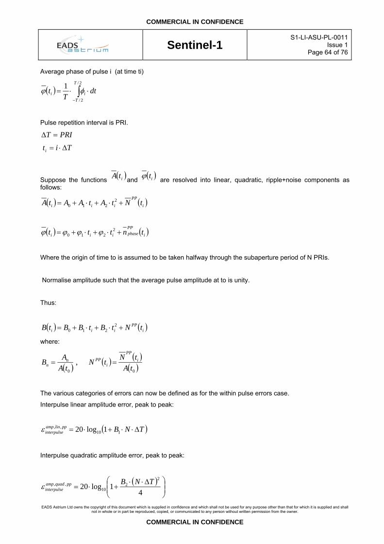
COMMERCIAL IN CONFIDENCE
Sentinel-1
S1-LI-ASU-PL-0011Issue 1
Page 64 of 76
EADS Astrium Ltd owns the copyright of this document which is supplied in confidence and which shall not be used for any purpose other than that for which it is supplied and shall
not in whole or in part be reproduced, copied, or communicated to any person without written permission from the owner.
COMMERCIAL IN CONFIDENCE
Average phase of pulse i (at time ti)
( ) ∫−
⋅⋅=2/
2/
1 T
Tii dt
Tt φϕ
Pulse repetition interval is PRI.
PRIT =∆
Titi ∆⋅=
Suppose the functions ( )itA and ( )itϕ are resolved into linear, quadratic, ripple+noise components as follows:
( ) ( )i
PP
iii tNtAtAAtA +⋅+⋅+= 2210
( ) ( )i
PPphaseiii tnttt +⋅+⋅+= 2
210 ϕϕϕϕ
Where the origin of time to is assumed to be taken halfway through the subaperture period of N PRIs.
Normalise amplitude such that the average pulse amplitude at to is unity.
Thus:
( ) ( )iPP
iii tNtBtBBtB +⋅+⋅+= 2210
where:
( ) ( ) ( )( )00
,tA
tNtNtA
AB iPP
iPPn
n ==
The various categories of errors can now be defined as for the within pulse errors case.
Interpulse linear amplitude error, peak to peak:
( )TNBpplinampinterpulse ∆⋅⋅+⋅= 110
,, 1log20ε
Interpulse quadratic amplitude error, peak to peak:
( )⎟⎟⎠
⎞⎜⎜⎝
⎛ ∆⋅⋅+⋅=
41log20
22
10,, TNBppquadamp
interpulseε

COMMERCIAL IN CONFIDENCE
Sentinel-1
S1-LI-ASU-PL-0011Issue 1
Page 65 of 76
EADS Astrium Ltd owns the copyright of this document which is supplied in confidence and which shall not be used for any purpose other than that for which it is supplied and shall
not in whole or in part be reproduced, copied, or communicated to any person without written permission from the owner.
COMMERCIAL IN CONFIDENCE
Interpulse amplitude error due to noise and ripple , one sigma:
( )( )( )iPPnoiseamp
interpulse tNSD+⋅= 1log20 101,, σε
Interpulse linear phase error, peak to peak and in units of degrees:
TNpplinphaseinterpulse ∆⋅⋅⋅⎟
⎠⎞
⎜⎝⎛= 1
,, 180 ϕπ
ε
Interpulse quadratic phase error, peak to peak and in units of degrees:
( )4
180 2
2,, TNppquadphase
interpulse∆⋅
⋅⋅⎟⎠⎞
⎜⎝⎛= ϕ
πε
Interpulse phase error due to noise and ripples , peak to peak and in units of degrees:
( )( )i
PPphase
ripplenoisephaseinterpulse tnSD⋅⎟
⎠⎞
⎜⎝⎛=+
πε σ 1801,,
8.4 Stability over time intervals Stability of parameters is defined over given time spans (e.g. in several cases over 10 minutes). It is to be considered that the satellite imposes temperature changes at TBD rate on the SES.

COMMERCIAL IN CONFIDENCE
Sentinel-1
S1-LI-ASU-PL-0011Issue 1
Page 66 of 76
EADS Astrium Ltd owns the copyright of this document which is supplied in confidence and which shall not be used for any purpose other than that for which it is supplied and shall
not in whole or in part be reproduced, copied, or communicated to any person without written permission from the owner.
COMMERCIAL IN CONFIDENCE
9. OTHER DEFINITIONS Term Explanation
Acquisition Acquisition is used in different meanings: atomic item generated by mission planning (a piece of information about an acquisition) raw data acquired by the satellite for a single product order item Note that for single product order items the relation between order items and acquisitions is n:1 where usually n is 1.
Acquisition (Datatake) The process of imaging by the Synthetic Aperture Radar. Acquisition Info Acquisition info contains in principle the acquisition IDs for a downlink and the decryption
keys. Acquisition of Signal Begin of a ground-station pass when the satellite comes with active transmitter over the
horizon as valid for the ground-station antenna or after the transmitter was turned on. Acquisition Planning feasibility The state of feasibility of an order taking into account the capabilities of the instrument and
the temporal and geometrical constraints. (see Feasibility Failure) Acquisition Planning inquiry A user's order for a radar acquisition of which the feasibility is not yet validated. Acquisition Planning Request An order for a radar acquisition, identified by a unique denominator
agreed between PGS and MOS including all planning relevant information.
Acquisition Planning Request The acquisition planning order defines the requested acquisition as an input for Mission Planning.
Auxiliary Data Provision Via the auxiliary data provision (MOS) the PGS can get auxiliary data needed for the TMSP SAR processing. The orbit information is provided in different time frames and corresponding precisions: preliminary, NRT, precise, high precise.
Auxiliary Product Ingestion The auxiliary product ingestion processing system gets all orbits provided by the auxiliary product provision of the MOS and transfers them to the Product Library for cataloguing and archiving. The TMSP SAR processing searches and retrieves corresponding auxiliary products for level 1 processing.
Auxiliary Products Auxiliary products are needed for the processing of primary instrument data. In the context of Sentinel-1 orbit files, attitude files, calibration data and instrument characteristics are needed for L0 and L1b processing. Each of these data classes may correspond to an auxiliary product type.
Availability Profile (Slot File) Information of a downlink station's availability or foreseeable outages. Background Order A background order is a kind of order (item) that specifies acquisitions for archiving of L0
products, but without immediate delivery. Basic Product Basic Products are the processed Sentinel-1 SAR images to be delivered to the user. Central Checkout System (CCS)
User Interface to the spacecraft and subsystems via the manufacturer-supplied EGSE during the AIT-phase. The CCS provides the two-way interface (Telemetry and telecommand) to the spacecraft and is provided and operated by GSOC.
Coverage Order A coverage order is a kind of order (item) that specifies a region of interest to be covered by acquisitions.
Coverage Pre-check The coverage pre-check checks the theoretical feasibility of a possible order with respect to the specified satellite/instrument parameters, the specified region of interest and the specified acquisition time window.
Data Quality Check Product The collection of parameters and quicklooks that are required to monitor the health of the SAR sensor and the quality of the acquired data.
Data Transfer System Automatic or semi-automatic controlled processes at GSOC for transfer (copying or moving) data-files from one location to one or several other destinations either regularly (configurable schedule) or on request
Delivery Package A delivery package corresponds to a user order. It contains products for order items. Delivery Product A delivery product is the result of a post-processing step in order to meet the users needs
(e.g. specified format). It may temporarily be stored in the Product Library for delivery by Online/Offline Product Generation&Delivery
Direct Access Customer A special Customer, e.g. in the reconnaissance field. The received data are solely used to produce geo-information products for its own and private applications
Direct Access Partner A partner acts as regional affiliate of Infoterra. In his Region of Interest (ROI) he has all commercial rights for acquisition of data and marketing of the corresponding products. Compatible Geo-information products are produced and sold to the market

COMMERCIAL IN CONFIDENCE
Sentinel-1
S1-LI-ASU-PL-0011Issue 1
Page 67 of 76
EADS Astrium Ltd owns the copyright of this document which is supplied in confidence and which shall not be used for any purpose other than that for which it is supplied and shall
not in whole or in part be reproduced, copied, or communicated to any person without written permission from the owner.
COMMERCIAL IN CONFIDENCE
Term Explanation Downlink A downlink (dump) is the data received by a receiving station at a single pass of the satellite,
contains acquisitions (or fragments of acquisitions in some cases). Downlink (Datadump) The process of transmitting SAR data to the ground station. Downlink Info Downlink info in principle contains the start and stop time for reception. It is identified by
orbit (or time) and receiving station. It is used for reception planning. Dual Polarization Mode Transmit and receive polarization switch using interleaved pulse strategy resulting in two
image layers. Dump Synonym for the process of reading out stored data from onboard memory and transmitting
it to the ground-station at a high data-rate Execution Planning The process of establishing a timeline of spacecraft and ground activities closest to the time
of execution taking into consideration the latest acceptable acquisition planning request. The goal is to establish automated rule based execution planning in accordance with the guidelines given by the strategic planning.
Footprint A footprint is an area on the earth surface which is described by a polygon. an area on the earth surface covered by an earth observation product => product footprint an area on the earth surface illuminated by a radar antenna => antenna footprint
Footprint Beam Database A Data Base holding information about the accessibility of geographical locations by the available radar beams assuming an orbit which is steered at high precision.
Future Product A future product is an order item that specifies a product which needs an acquisition and subsequent processing.
Instrument Command Generator
A facility which translates the settings of the SAR instrument, which are produced by the Radar Parameter Generator, into instrument specific commands for up-link.
Key Encryption key used to establish a secure, non-interferable downlink of SAR data. Launch and Early Orbit Phase Sum and sequence of all activities from the moment the launcher-countdown is initiated until
the spacecraft is in a stable and secure configuration in orbit. This phase is typically characterised by around the clock shift-work, special safety requirements and additional ground-network resources needed to perform all necessary activities within the time-frame available.
Loss of Signal End of a ground-station pass as the satellite disappears with active transmitter behind the horizon-mask as valid for the ground-station antenna or after the transmitter was turned off.
Mission Planning System Part of the MOS which consists of all tools and processes necessary to establish a feasible and optimised timeline for spacecraft and ground activities.
Mission programmable Means programmable but fixed for a particular mission i.e. not modifiable via telecommand.
Online/Offline Product Generation
Online/Offline Product Generation produces a delivery package based on (delivery) products.
Operating Tool The operating tool provides unified, interactive monitoring and control of DIMS services and processing systems.
Orbit Info Orbit info contains two line elements with orbit parameters used by receiving stations. Orbit Info (TLE) An appropriate format (TLE TBC) to communicate the spacecraft's orbit Order Accounting Order Accounting is implemented by a commercially available software (SAP). The user
order is handed over from Ordering Control for commercial treatment. Order Accounting is responsible for managing quotes, invoices, delivery papers, reports and the customer and prices data base.
Order Management Order Management handles the business process “ordering” throughout DIMS. It is split into two components, Ordering Control and Order Accounting.
Ordering Control Ordering Control handles incoming orders from the User Information Services. It verifies the user order with help of the Product Library information, user and crisis area information. If requested, it initiates an acquisition. If necessary, it initiates the processing of the ordered product. Finally, it requests a post-processing (e.g. formatting) and the delivery product generation to satisfy the user order.
Performance Estimator Software tool which is used to analyse the interdependence of SAR system parameters on each other and on the image quality.
Processing System A processing system is the operational unit responsible for the processing of products of one
COMMERCIAL IN CONFIDENCE
Sentinel-1
S1-LI-ASU-PL-0011Issue 1
Page 68 of 76
EADS Astrium Ltd owns the copyright of this document which is supplied in confidence and which shall not be used for any purpose other than that for which it is supplied and shall
not in whole or in part be reproduced, copied, or communicated to any person without written permission from the owner.
COMMERCIAL IN CONFIDENCE
Term Explanation or more product types. The actual processing is done by one or more processors. Administrative tasks like cache management and scheduling are performed by the processing system management (PSM).
Processor A standard processor is a complex processing algorithm able to convert lower level products to higher level products. Auxiliary processors are used for example to handle metadata or manage files.
Producible Product A producible product is an order item that specifies a product that can be generated from products existing in the Product Library.
Product A product is a defined earth observation data set which is composed of metadata and data files. It is build up by one or more components like primary data or quicklook which are assigned to a specific processing level. A product is either a reference product which is subject for long-term archiving or a delivery product which is temporarily available for customer delivery. A product can be managed as an item in the Product Library.
Product Type A product type is a collection of products with the same characteristics, e.g. with the same mission, sensor and processing level.
Production Control Production control is instructed by Ordering Control for the acquisition/production of a product which is not available in the Product Library. Therefore, it organizes processing chain to produce the ordered product. Production Control identifies the relevant processing systems and reports status back to production control.
Radar Parameter Generator A facility which determines the optimal settings of the SAR instrument on the basis of relevant SAR system parameters and order parameters.
Receiving Station The receiving station is a system, which is able to receive TX-data at X-band and S-band frequencies with the desired quality and in the desired elevation range and which enables all steps up to the generation of SAR acquisition files and its decryption.
SAR Signal Data File RS-decoded and decrypted instrument source packets extracted from transfer frames. Sequence of Events Chronological listing of all major activities (on system and subsystem level) during the
Launch and Early Orbit Phase (see above) or other phases to achieve the mission goal for this specific phase. The SoE lists and calls relevant procedures, where all detailed activities are defined.
SpotLight High resolution SAR imaging mode with one beam, azimuth antenna steering and therefore limited azimuth extent of acquisition.
Strategic Planning The purpose of strategic planning is to express the intention of the project management in agreement with all user groups how to make use of the Sentinel-1 space and ground egment. This may comprises the establishment of protected time-slots, apportionment of available acquisition and reception time, assignment of priorities and acquisition time-windows and definition of decision rules for more detailed planning stages. The strategic planning is supported by the Mission Planning System by indicating predictable conflicts, by determining gradually evolving shortages and by proposing alternative options.
StripMap Standard SAR imaging mode with one beam and unlimited acquisition length. Swath Preview The swath preview shows the maximum possible field of view of the instrument on the earth
surface within a given time window. Time Tag A time-stamp (relative or absolute) assigned to a telecommand which is planned for
automatic execution on-board at the defined time. User A user is a person that uses EOWEB to browse and order acquisitions or products. User Information Services The user information services offer interactive user services, namely information retrieval,
product guide and directory, product inventory and browse, ordering, order follow-up and delivery (via pickup-point).
User programmable Means settable via telecommand via the C&C bus. User Order A user order is a binding request to acquire or deliver certain products, issued by a user
through EOWEB. It defines the user requested order items (products), user information itself and order, processing and delivery options.
Validation The procedure for ascertaining that an intended use or application (of a product or service) is successful.
Verification The procedure for ascertaining that a requirement/specification is met.

COMMERCIAL IN CONFIDENCE
Sentinel-1
S1-LI-ASU-PL-0011Issue 1
Page 69 of 76
EADS Astrium Ltd owns the copyright of this document which is supplied in confidence and which shall not be used for any purpose other than that for which it is supplied and shall
not in whole or in part be reproduced, copied, or communicated to any person without written permission from the owner.
COMMERCIAL IN CONFIDENCE
10. ECSS TERMS
10.1 ECSS-E-10-02A Acceptance stage
A verification stage with the objective of demonstrating that the product is free of workmanship defects and integration errors and ready for its intended use. Analysis
A verification method which entails performing a theoretical or empirical evaluation by accepted analytical techniques. The selected techniques may typically include systematics, statistics, qualitative design analysis, modelling and computer simulation (see also ECSS-P-001A Rev.1 3.5). Assembly
The process of mechanical mating hardware to obtain a low level configuration after the manufacturing process (see also ECSS-P-001A Rev.1 3.9). In-orbit stage
The verification stage valid for projects whose characteristics (e.g. mission, in-orbit operations) require in-orbit verification. Inspection
A verification method that determines conformance to requirements for constructional features, document and drawing conformance, workmanship and physical conditions without the use of special laboratory equipment, procedures or services (see also ECSS-P-001A Rev.1 3.73). Integration
The process of physically and functionally combining lower level products (hardware and/or software) to obtain a particular functional configuration. Model philosophy
The definition of the optimum number and characteristics of physical models required to achieve a high confidence in the product verification with the shortest planning and a suitable weighing of costs and risks. Post-landing stage
The verification stage valid for projects whose characteristics require post-landing verification (e.g. multimission projects). Pre-launch stage
The verification stage with the objective to verify that the flight article is properly configured for launch and, to the extent practical, it is capable to function as planned for launch. Qualification stage
The verification stage with the objective to demonstrate that the design meets the applicable requirements including proper margins. Review-of-design
A verification method using validation of previous records or evidence of validated design documents, when approved design reports, technical descriptions and engineering drawings unambiguously show that the requirement is met. Test
A verification method wherein requirements are verified by measurement of product performance and functions under various simulated environments (see also ECSS-P-001A Rev.1 3.147). Verification Level
The product architectural level at which the relevant verification is performed.

COMMERCIAL IN CONFIDENCE
Sentinel-1
S1-LI-ASU-PL-0011Issue 1
Page 70 of 76
EADS Astrium Ltd owns the copyright of this document which is supplied in confidence and which shall not be used for any purpose other than that for which it is supplied and shall
not in whole or in part be reproduced, copied, or communicated to any person without written permission from the owner.
COMMERCIAL IN CONFIDENCE
10.2 ECSS-E-10-03A Airborne Support Equipment (ASE) Equipment installed in a recoverable launch vehicle to provide support functions and interfaces for the spacecraft during launch and orbital operations of the recoverable launch vehicle
• NOTE ASE includes the hardware and software that provides the structural, electrical, electronic and mechanical interfaces with the launch vehicle. ASE is recovered with the launch vehicle.
Burst Pressure
Maximum test pressure that pressurized equipment withstands without rupture to demonstrate the adequacy of the design in a qualification test
• NOTE 1 Burst pressure is equal to the product of the maximum expected operating pressure, a burst pressure design factor, and a factor corresponding to the differences in material properties between test and design temperatures.
• NOTE 2 An item subjected to a burst pressure test is not used for other purposes.
Design Environments
Composite of the various environmental loads, to which the hardware is designed • NOTE Each of the design environments is based upon:
• the maximum and minimum predicted environments during the operational life of the item; • the qualification margin that increases the environmental range to provide an acceptable level of
confidence that a failure does not occur during the service life of the item; • uncertainties and tolerances related to the analytical prediction.
Environmental Design Margin
Increase of the environmental extremes for the purpose of design and qualification above the levels expected during the life cycle
• NOTE Environmental design margin includes levels such as mechanical, thermal, radiation as well as the time of exposure of them.
Environmental Test
Simulation of the various constraints (together or separately) to which an item is subjected during its operational life cycle
• NOTE Environmental tests cover natural and induced environments. Fundamental Resonance (for Structural Modes) first major significant resonances as observed during one-axis vibration test for each of the three test axes
fundamental resonance (for structural modes)
first major significant resonances as observed during one-axis vibration test for each of the three test axes • NOTE 1 The term fundamental resonance is used in conjunction with notching of sinusoidal vibration input
spectrum for item qualification. • NOTE 2 Significant resonances are modes that have an effective mass greater than 10 % of the total mass of
the item.
Integrated System Test
Test that has the scope to verify that the performance of the element meets the specification requirements, in terms of correct operation in all operational modes, including back-up modes and all foreseen transients.
• NOTE Integrated system test is also known as system functional test.
Integrated System Check
Sub-set of the integrated system test, able to involve all major functions, at the maximum extent automatically performed and with the scope to provide the criteria for judging successful survival of the element in a given test environment, with a high degree of confidence, in a relatively short time.
• NOTE Integrated system check is also known as abbreviated functional test.

COMMERCIAL IN CONFIDENCE
Sentinel-1
S1-LI-ASU-PL-0011Issue 1
Page 71 of 76
EADS Astrium Ltd owns the copyright of this document which is supplied in confidence and which shall not be used for any purpose other than that for which it is supplied and shall
not in whole or in part be reproduced, copied, or communicated to any person without written permission from the owner.
COMMERCIAL IN CONFIDENCE
Limit Load
Maximum anticipated load, or combination of loads, which a structure is expected to experience during the performance of specified missions in specified environments.
• NOTE Since the actual loads that are experienced in service are in part random in nature, statistical methods for predicting limit loads are generally employed.
Low Level Sinusoidal Vibration
Exposing an item to a frequency sweep of low level sinusoidal vibrations to show possible deficiencies in workmanship, as a consequence of another environment.
• NOTE Low level sinusoidal vibration test is also known as signature test.
Maximum Predicted Acceleration
Acceleration value determined from the combined effects of the quasi steady acceleration and the transient response of the vehicle to engine ignition, engine burn-out and stage separation.
• NOTE Where the natural frequency of the equipment mount or mounting structure can couple with engine initiated transients, the maximum predicted acceleration level accounts for the possible dynamic amplification.
Maximum Predicted Acoustic Environment
Maximum value of the time average r.m.s. SPL (sound pressure level) in each frequency band occurring below payload fairing or within STS orbiter cargo bay, which occurs during lift-off, powered flight or re-entry.
• NOTE The maximum predicted acoustic environment test spectrum is specified in octave or 1/3 octave bands over a frequency range of 31,5 Hz to 10 000 Hz. The duration of the maximum environment is the total period when the overall amplitude is within 6 dB of the maximum overall amplitude.
Maximum Predicted Operating Pressure
Working pressure applied to equipment by the pressurizing system with the pressure regulators and relief valves at their upper operating limit, including the effects of temperature, transient peaks and vehicle acceleration. Maximum Predicted Pyro Shock Environment
Maximum absolute shock response spectrum determined by the response of a number of single degree of freedom systems using an acceleration amplification factor at the resonant frequency of lightly damped system (Q = 10).
• NOTE 1 The shock response spectrum is determined at frequency intervals of one-sixth octave or less over a frequency range of 100 Hz to 4 000 Hz or more.
• NOTE 2 The pyro shock environment imposed on the spacecraft equipment is due to structural response when the space or launch vehicle electro-explosive devices are activated. Resultant structural response accelerations have the form of superimposed complex decaying sinusoids that decay to a few percent of their maximum acceleration in 5ms to 15ms.
Maximum Predicted Random Vibration Environment
Random vibration environment imposed on the spacecraft, subsystems and equipment due to the lift-off acoustic field, aerodynamic excitations, and transmitted structure-borne vibration.
• NOTE 1 A different spectrum can exist for different equipment zones or for different axis. The equipment vibration levels are based on vibration response measurements made at the equipment attachment points during ground acoustic tests or during flight. The duration of the maximum environment is the total period during flight when the overall level is within 6 dB of the maximum overall level.
• NOTE 2 The Power spectral density is based on a frequency resolution of 1/6 octave (or narrower) bandwidth analysis, over a frequency range of 20 Hz to 2 000 Hz

COMMERCIAL IN CONFIDENCE
Sentinel-1
S1-LI-ASU-PL-0011Issue 1
Page 72 of 76
EADS Astrium Ltd owns the copyright of this document which is supplied in confidence and which shall not be used for any purpose other than that for which it is supplied and shall
not in whole or in part be reproduced, copied, or communicated to any person without written permission from the owner.
COMMERCIAL IN CONFIDENCE
Maximum Predicted Sinusoidal Vibration Environment
Predicted environment imposed on the spacecraft, subsystems and equipment due to sinusoidal and narrow band random forcing functions within the launch vehicle or spacecraft during flight or from ground transportation and handling.
• NOTE 1 In flight, sinusoidal excitations are caused by unstable combustion, by coupling of structural resonant frequencies (POGO), or by imbalances in rotating equipment in the launch vehicle or spacecraft. Sinusoidal excitations occur also during ground transportation and handling due to resonant responses of tires and suspension systems of the transporter.
• NOTE 2 The maximum predicted sinusoidal vibration environment is specified over a frequency range of 5 Hz to 100 Hz for flight excitation.
Maximum And Minimum Predicted Equipment Temperatures
Highest and lowest temperatures that are expected to occur in flight on each equipment of the spacecraft during all operational and non-operational modes which include uncertainties. Moving Mechanical Assemblies
Mechanical or electromechanical devices that control the movement of one mechanical part of a spacecraft relative to another part.
• NOTE Moving mechanical assemblies include: deployment mechanisms, pointing mechanisms, drive mechanisms, design mechanisms and the actuators, motors, linkages, latches, clutches, springs, cams, dampers, booms, gimbals, gears, bearings and instrumentation that are an integral part of these mechanical assemblies (e.g. recorders).
Multipacting
Resonant back and forth flow of secondary electrons in a vacuum between two surfaces separated by a distance such that the electron transit time is an odd integral multiple of one half the period of the alternating voltage impressed on the surface.
• NOTE 1 Multipacting does not occur unless an electron impacts one surface to initiate the action, and a secondary emission of one or more electrons at each surface to sustain the action takes place.
• NOTE 2 Multipacting is an unstable self-extinguishing action which occurs at pressures less than 6,65 × 10⁻² hPa, however, it becomes stable at a pressure less than 1,33 × 10⁻³ hPa.
• NOTE 3 The pitting action resulting from the secondary emission of electrons degrades the impacted surfaces. The secondary electron emission can also increase the pressure in the vicinity of the surfaces causing ionisation (corona) breakdown to occur.
• NOTE 4 These effects can cause degradation of performance or permanent failure of the radio frequency cavities, waveguides or other devices involved.
Notching of Sinusoidal Vibration Input Spectrum
Notching of the shaker input spectrum to limit structural responses at resonant frequencies according to qualification or acceptance loads.
• NOTE Notching of sinusoidal vibration input spectrum is a general accepted practise in vibration testing.
Operational Modes
Combination of operational configurations or conditions that can occur during the service life for equipment or spacecraft.
• EXAMPLE Power-on or power-off, command modes, readout modes, attitude control modes, antenna stowed or deployed, and spinning or de-spun.
Proof Pressure
Test pressure for pressurized equipment to sustain without detrimental deformation. • NOTE 1 The proof pressure is used to give evidence of satisfactory workmanship and material quality, or to
establish maximum possible flaw size. • NOTE 2 The proof pressure is equal to the product of maximum expected operating pressure (see 3.1.15),
proof pressure design factor, and a factor accounting for the difference in material properties between test and design temperature.
COMMERCIAL IN CONFIDENCE
Sentinel-1
S1-LI-ASU-PL-0011Issue 1
Page 73 of 76
EADS Astrium Ltd owns the copyright of this document which is supplied in confidence and which shall not be used for any purpose other than that for which it is supplied and shall
not in whole or in part be reproduced, copied, or communicated to any person without written permission from the owner.
COMMERCIAL IN CONFIDENCE
Service Life
Total life expectancy of an item, equipment or space vehicle. • NOTE The service life starts at the completion of assembly of the item and continues through all acceptance
testing, handling, storage, transportation, launch operations, orbital operations, refurbishment, retesting, re-entry or recovery from orbit, and reuse if applicable.
Space Element
Product or set of products intended to be operated in outer space. • NOTE 1 In order to avoid repetition in the level of decomposition of the space product, the term element is
used to define .systems within the system.. The term element is used to identify any system within the space system.
• NOTE 2 Elements that operate entirely in space or on the ground are referred to as Space segment and Ground Segment, respectively.
Space Vehicle
integrated set of subsystems and equipment capable of supporting an operational role in space. • NOTE A space vehicle can be an orbiting vehicle, a major portion of an orbiting vehicle, or a payload that
performs its mission while attached to a launch or upper-stage vehicle. The ground support equipment is considered to be a part of the space vehicle.
Stabilized Test Temperature
Specified temperature for equipment and subsystem tests that has been achieved and has not changed by more than 1ºC during the previous one-hour period.
• NOTE During system level tests, performance verification testing may be started when the rate of change is below 1ºC within a time period equal or near the time constant of the spacecraft.
Temperature Reference, Reference Point
Physical point located on the equipment providing a simplified representation of the equipment thermal status.
• NOTE 1 Depending upon the equipment dimensions, more than one temperature reference may be defined. • NOTE 2 The temperature of the reference point is measured by temperature sensors during test. The
temperature distribution within the equipment and hot spots on the external casing due to point heat sources are not used as reference points.
Ultimate Load
Maximum static load to which a structure is designed. • NOTE It is obtained by multiplying the limit load by the ultimate factor of safety.
COMMERCIAL IN CONFIDENCE
Sentinel-1
S1-LI-ASU-PL-0011Issue 1
Page 74 of 76
EADS Astrium Ltd owns the copyright of this document which is supplied in confidence and which shall not be used for any purpose other than that for which it is supplied and shall
not in whole or in part be reproduced, copied, or communicated to any person without written permission from the owner.
COMMERCIAL IN CONFIDENCE
10.3 ECSS-E-20A Centroid Error Function (CEF)
Difference between the position of the barycentre of the Point Spread Function (PSF), calculated by means of a suitable algorithm, and the theoretical position of the PSF centre, given by the intersection of the corresponding chief ray with the image plane. The centroid algorithm evaluates the position of the PSF energy barycentre and it is based on the energy measurement on a predetermined number of pixels in the image plane. Encircled Energy Function (EEF)
The fraction of the PSF energy which lies within a circle, evaluated as a function of the circle radius. Field Of View (FOV)
Angular extent of the object space which can be detected by an optical system or instrument. (The FOV is not be always symmetrical about the optical axis). Instantaneous Field Of View (IFOV)
Angular extent of the object space which can be detected by an optical system or instrument, during a negligible time interval. (The IFOV is not be always symmetrical about the optical axis). Line Spread Function (LSF)
One-dimensional transverse energy distribution in the image of a narrow slit object. Modulation Transfer Function (MTF)
The modulation transfer function is the modulus of the optical transfer function. Considering a sine wave pattern object, the MTF is found to be the ratio of the modulation in the image to that in the object as a function of the spatial frequency of the sine wave pattern. Noise Equivalent Power (NEP)
The Noise Equivalent Power is the value of the detector input power which produces a detector output equal to the r.m.s. noise output within a stated bandwidth at a stated frequency. Optical Transfer Function (OTF)
It is the normalized Fourier transform of the point spread function Point Spread Function (PSF)
Two dimensional energy distribution in the image of an object point. Wavefront error (WFE)
Distribution of the distance between the wavefront exiting from an optical system and a reference wavefront or surface, measured on the normal to the reference wavefront and expressed in wavelength units.

COMMERCIAL IN CONFIDENCE
Sentinel-1
S1-LI-ASU-PL-0011Issue 1
Page 75 of 76
EADS Astrium Ltd owns the copyright of this document which is supplied in confidence and which shall not be used for any purpose other than that for which it is supplied and shall
not in whole or in part be reproduced, copied, or communicated to any person without written permission from the owner.
COMMERCIAL IN CONFIDENCE
11. COMMERCIAL The definitions below are from the point of view of the SES level :-
The Agency – Mission Prime
The European Space Agency (ESA)
Industrial End Customer – Spacecraft Prime
Thales Alenia Space Italia S.p.A (TAS-I)
Industrial Customer – Payload Prime
Astrium GmbH, Friedrichshafen (ASD)
Customer – SES Prime
Astrium Ltd, Portsmouth (ASU)
Contractor
A company providing goods or services into the SES programme

COMMERCIAL IN CONFIDENCE
Sentinel-1
S1-LI-ASU-PL-0011Issue 1
Page 76 of 76
EADS Astrium Ltd owns the copyright of this document which is supplied in confidence and which shall not be used for any purpose other than that for which it is supplied and shall
not in whole or in part be reproduced, copied, or communicated to any person without written permission from the owner.
COMMERCIAL IN CONFIDENCE
DOCUMENT CHANGE DETAILS
Issue Issue Date Change Authority Class Relevant Information/Instructions
1 First Issue
2 Up Issue
DISTRIBUTION LIST
INTERNAL
EXTERNAL
Configuration Management (FileNet)