commercial in confidence - gas detection for labs ... manual commercial in confidence mec oem user...
TRANSCRIPT
Analox Limited 15 Ellerbeck Court, Stokesley Business Park,
North Yorkshire, TS9 5PT, UK
UK/RoW T: +44 (0)1642 711400 F: +44 (0)1642 713900
US T: (714) 891-4478
W: www.analox.net E: [email protected]
Copyright © 2014 Analox Ltd. All Rights Reserved.
MEC OEM
User Manual
Commercial in Confidence

MEC OEM
User Manual Int. Approved
Document ref: MEC-802-12 August 2018 Page 3 of 30
Copyright © 2014 Analox Ltd. All Rights Reserved.
Commercial in Confidence
List of Contents
List of Contents ............................................................................. 3
1 Safety information .................................................................... 6
2 About the MEC .......................................................................... 8 2.1 MEC variants available ........................................................................................... 9
3 Installation ............................................................................. 10 3.1 Physical mounting ............................................................................................... 10 3.2 Gas connections .................................................................................................. 12 3.3 Electrical connections (External) ............................................................................ 12 3.4 Electrical connections (Internal) ............................................................................ 13 3.5 Power/Comms connections ................................................................................... 13 3.6 4-20mA MEC....................................................................................................... 14 3.7 Sensor connections .............................................................................................. 14 3.8 RS485 communication ......................................................................................... 15 3.9 Operation ........................................................................................................... 15
4 Sensor replacement ................................................................ 16 4.1 Oxygen sensor replacement .................................................................................. 16 4.2 Toxic gas sensors ................................................................................................ 19 4.3 Helium sensor replacement................................................................................... 21
5 Calibration .............................................................................. 22 5.1 Performing a calibration ....................................................................................... 23
6 Spares and Accessories ........................................................... 26
7 Specifications.......................................................................... 27 7.1 MEC-O2 ............................................................................................................. 27 7.2 MEC-CO (20ppm range) ....................................................................................... 27 7.3 MEC-CO (500ppm range) ..................................................................................... 27 7.4 MEC-H2S ............................................................................................................ 28 7.5 MEC-NO2 ........................................................................................................... 28 7.6 MEC-NO ............................................................................................................. 28 7.7 MEC-SO2 ............................................................................................................ 29 7.8 MEC-He .............................................................................................................. 29 7.9 MEC 4-20mA....................................................................................................... 29
8 General care and disposal ....................................................... 30
MEC OEM
User Manual Int. Approved
Document ref: MEC-802-12 August 2018 Page 4 of 30
Copyright © 2014 Analox Ltd. All Rights Reserved.
Commercial in Confidence
List of figures
Figure 1 Mounting Drawing ......................................................................................... 10
Figure 2 Electrical Connections ................................................................................... 13
Figure 3 Calibration Equipment ................................................................................... 23
List of tables
Table 1 MEC Variants ................................................................................................... 9
Table 2 Electrical Connections ................................................................................... 12
Table 3 Internal Wiring Termination ......................................................................... 13
Table 4 Sensor Connections ....................................................................................... 14
Table 5 Toxic Gas Sensors ......................................................................................... 19
Table 6 Accessories ................................................................................................... 26
Table 7 Replacement Cells ......................................................................................... 26
Table 8 Recommended Calibration Gas ...................................................................... 26
MEC OEM
User Manual Int. Approved
Document ref: MEC-802-12 August 2018 Page 5 of 30
Copyright © 2014 Analox Ltd. All Rights Reserved.
Commercial in Confidence
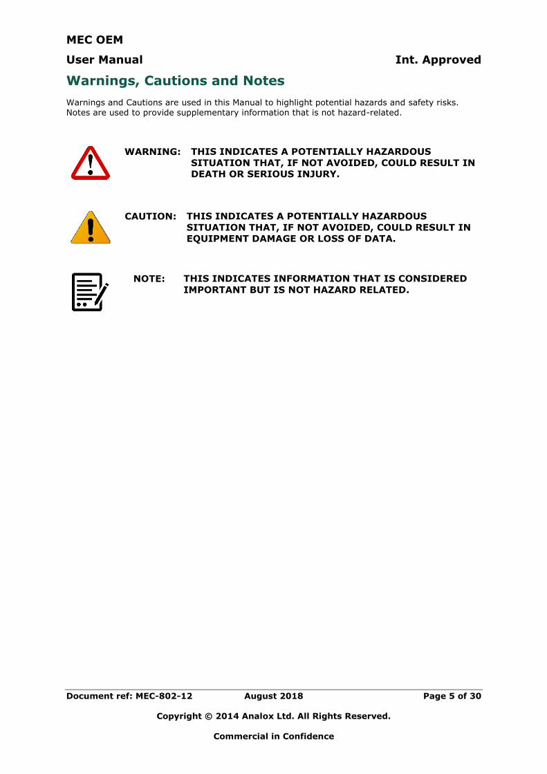
Warnings, Cautions and Notes
Warnings and Cautions are used in this Manual to highlight potential hazards and safety risks. Notes are used to provide supplementary information that is not hazard-related.
WARNING: THIS INDICATES A POTENTIALLY HAZARDOUS
SITUATION THAT, IF NOT AVOIDED, COULD RESULT IN
DEATH OR SERIOUS INJURY.
CAUTION: THIS INDICATES A POTENTIALLY HAZARDOUS
SITUATION THAT, IF NOT AVOIDED, COULD RESULT IN
EQUIPMENT DAMAGE OR LOSS OF DATA.
NOTE: THIS INDICATES INFORMATION THAT IS CONSIDERED
IMPORTANT BUT IS NOT HAZARD RELATED.
MEC OEM
User Manual Int. Approved
Document ref: MEC-802-12 August 2018 Page 6 of 30
Copyright © 2014 Analox Ltd. All Rights Reserved.
Commercial in Confidence
1 Safety information
WARNING: READ THE SAFETY INFORMATION FULLY BEFORE USING THE ANALOX MEC.
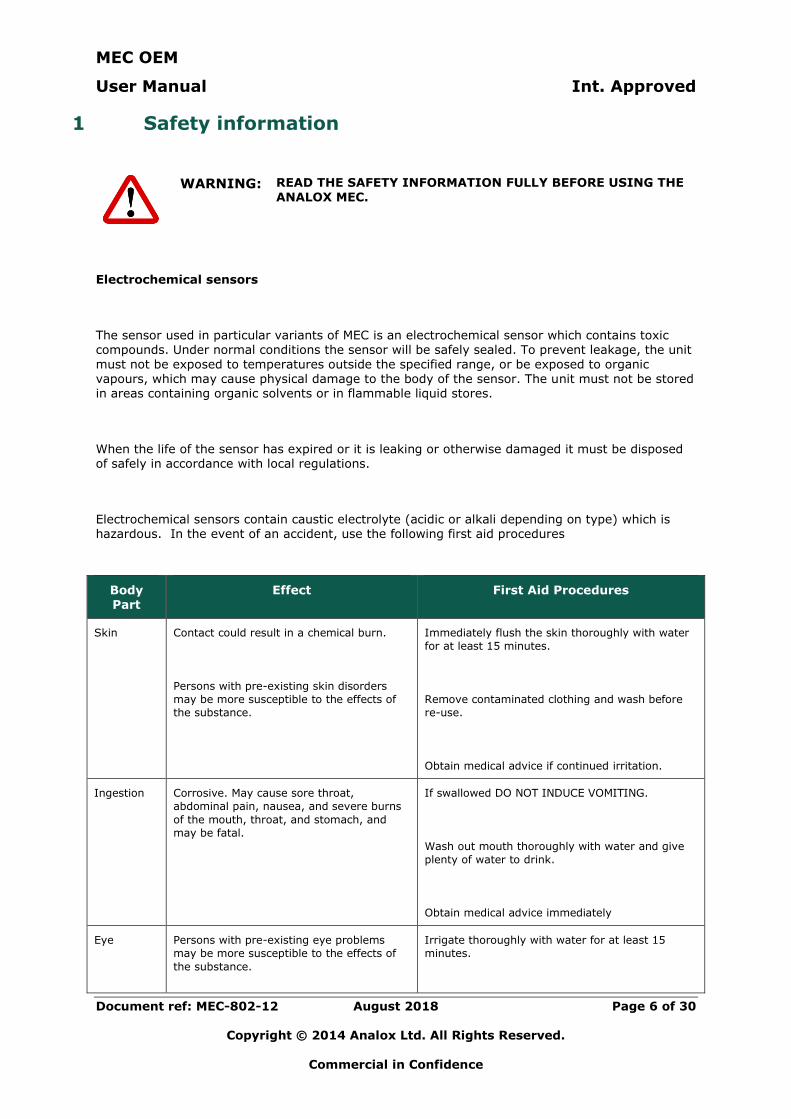
Electrochemical sensors
The sensor used in particular variants of MEC is an electrochemical sensor which contains toxic compounds. Under normal conditions the sensor will be safely sealed. To prevent leakage, the unit
must not be exposed to temperatures outside the specified range, or be exposed to organic vapours, which may cause physical damage to the body of the sensor. The unit must not be stored in areas containing organic solvents or in flammable liquid stores.
When the life of the sensor has expired or it is leaking or otherwise damaged it must be disposed of safely in accordance with local regulations.
Electrochemical sensors contain caustic electrolyte (acidic or alkali depending on type) which is hazardous. In the event of an accident, use the following first aid procedures
Body Part
Effect First Aid Procedures
Skin Contact could result in a chemical burn.
Persons with pre-existing skin disorders
may be more susceptible to the effects of
the substance.
Immediately flush the skin thoroughly with water
for at least 15 minutes.
Remove contaminated clothing and wash before
re-use.
Obtain medical advice if continued irritation.
Ingestion Corrosive. May cause sore throat,
abdominal pain, nausea, and severe burns
of the mouth, throat, and stomach, and
may be fatal.
If swallowed DO NOT INDUCE VOMITING.
Wash out mouth thoroughly with water and give
plenty of water to drink.
Obtain medical advice immediately
Eye Persons with pre-existing eye problems
may be more susceptible to the effects of
the substance.
Irrigate thoroughly with water for at least 15
minutes.
MEC OEM
User Manual Int. Approved
Document ref: MEC-802-12 August 2018 Page 7 of 30
Copyright © 2014 Analox Ltd. All Rights Reserved.
Commercial in Confidence
Body
Part
Effect First Aid Procedures
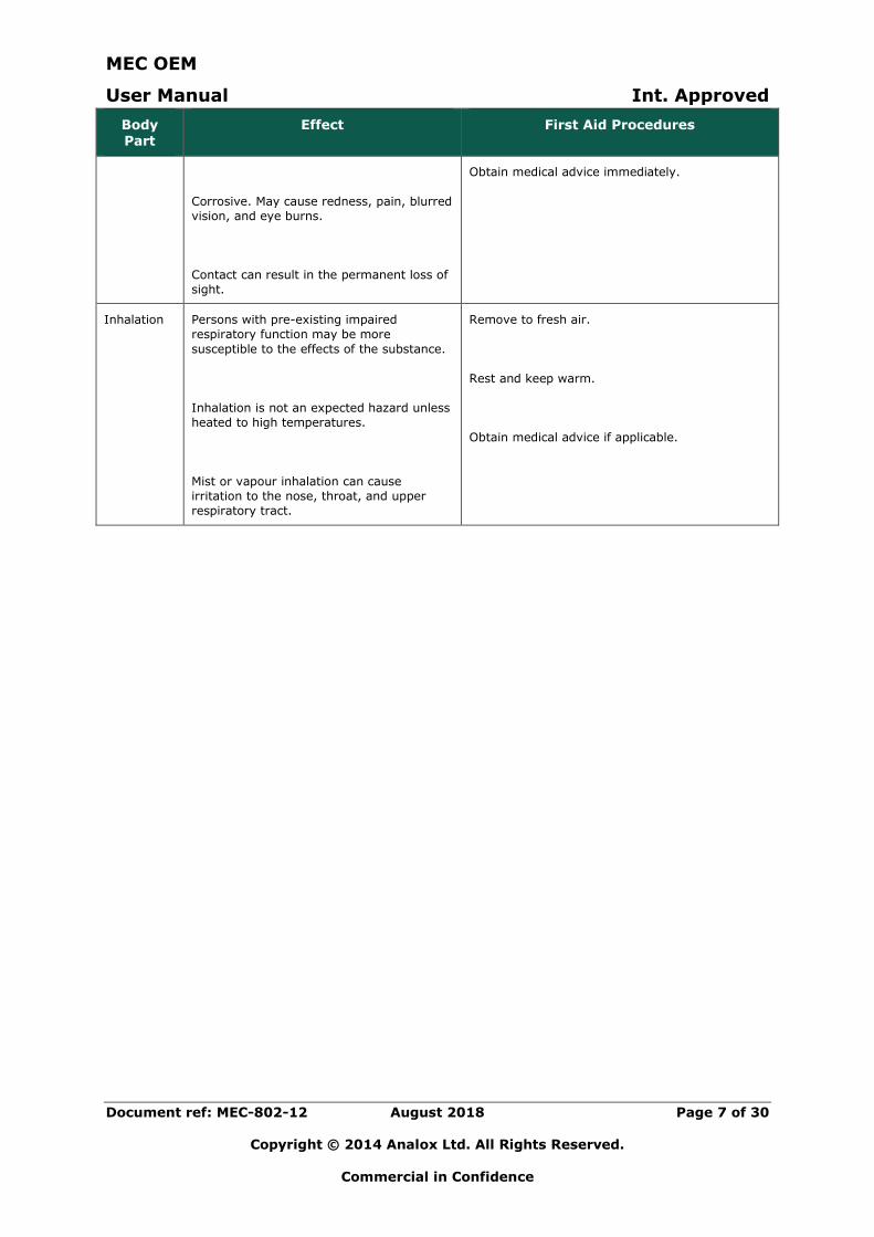
Corrosive. May cause redness, pain, blurred
vision, and eye burns.
Contact can result in the permanent loss of
sight.
Obtain medical advice immediately.
Inhalation Persons with pre-existing impaired
respiratory function may be more
susceptible to the effects of the substance.
Inhalation is not an expected hazard unless
heated to high temperatures.
Mist or vapour inhalation can cause
irritation to the nose, throat, and upper
respiratory tract.
Remove to fresh air.
Rest and keep warm.
Obtain medical advice if applicable.
MEC OEM
User Manual Int. Approved
Document ref: MEC-802-12 August 2018 Page 8 of 30
Copyright © 2014 Analox Ltd. All Rights Reserved.
Commercial in Confidence
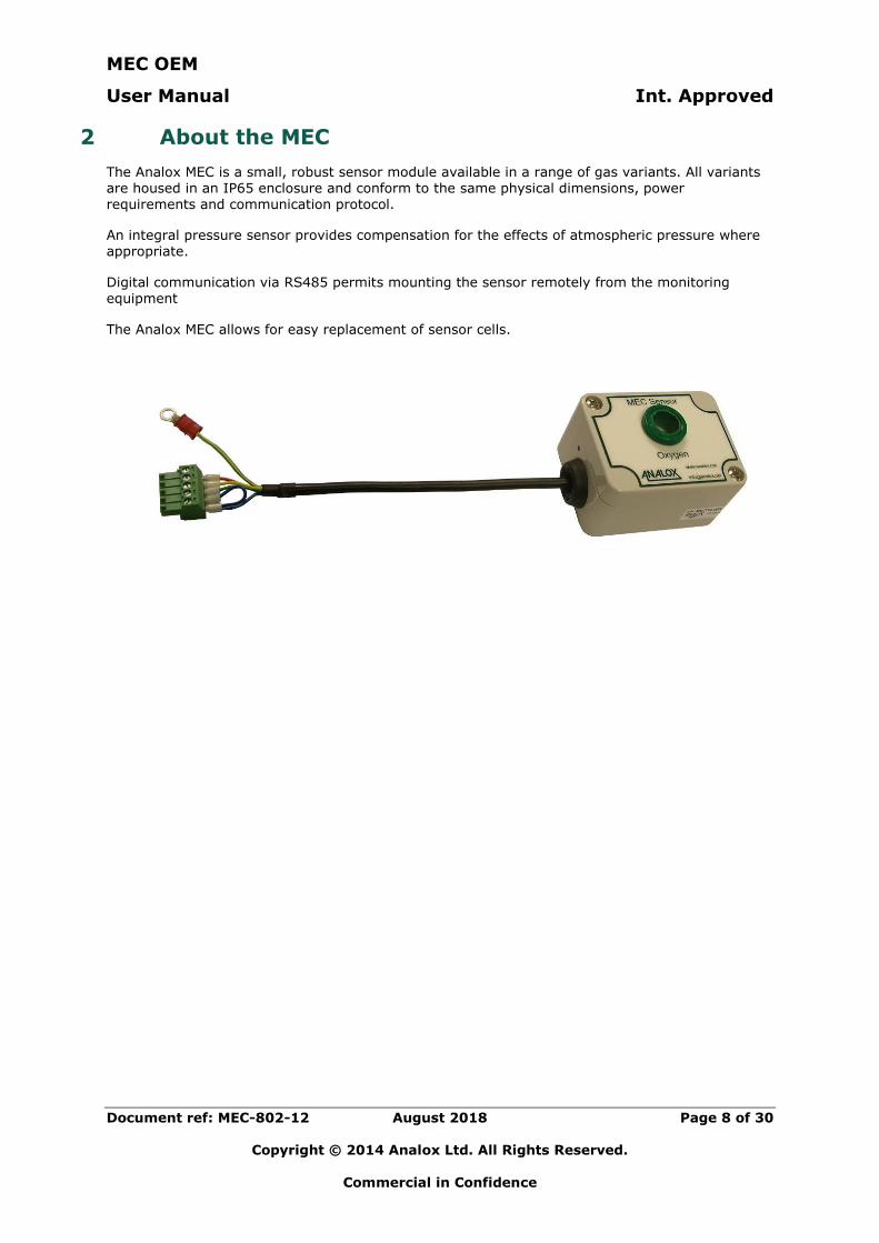
2 About the MEC
The Analox MEC is a small, robust sensor module available in a range of gas variants. All variants are housed in an IP65 enclosure and conform to the same physical dimensions, power requirements and communication protocol.
An integral pressure sensor provides compensation for the effects of atmospheric pressure where appropriate.
Digital communication via RS485 permits mounting the sensor remotely from the monitoring equipment
The Analox MEC allows for easy replacement of sensor cells.
MEC OEM
User Manual Int. Approved
Document ref: MEC-802-12 August 2018 Page 9 of 30
Copyright © 2014 Analox Ltd. All Rights Reserved.
Commercial in Confidence
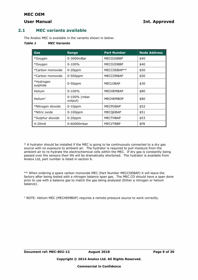
2.1 MEC variants available
The Analox MEC is available in the variants shown in below:
Table 1 MEC Variants
Gas Range Part Number Node Address
*Oxygen 0-3000mBar MECO2ABBP $40
*Oxygen 0-100% MECO2DBBP $40
*Carbon monoxide 0-20ppm MECCOEBAP** $50
*Carbon monoxide 0-500ppm MECCORBAP $50
*Hydrogen
sulphide 0-50ppm MECUJBAP $30
Helium 0-100% MECHEMBAP $80
Helium1 0-100% (mbar output)
MECHEMBDP $80
*Nitrogen dioxide 0-10ppm MECPGBAP $52
*Nitric oxide 0-100ppm MECQKBAP $51
*Sulphur dioxide 0-20ppm MECTHBAP $53
4-20mA 0-60000mbar MECVTBBP $F8
* A hydrator should be installed if the MEC is going to be continuously connected to a dry gas source with no exposure to ambient air. The hydrator is required to pull moisture from the
ambient air to re-hydrate the electrochemical cells within the MEC. If dry gas is constantly being passed over the sensors their life will be dramatically shortened. The hydrator is available from Analox Ltd, part number is listed in section 6.
** When ordering a spare carbon monoxide MEC (Part Number MECCOEBAP) it will leave the factory after being tested with a nitrogen balance span gas. The MEC CO should have a span done prior to use with a balance gas to match the gas being analysed (Either a nitrogen or helium balance).
1 NOTE: Helium MEC (MECHEMBDP) requires a remote pressure source to work correctly.
MEC OEM
User Manual Int. Approved
Document ref: MEC-802-12 August 2018 Page 10 of 30
Copyright © 2014 Analox Ltd. All Rights Reserved.
Commercial in Confidence
3 Installation
3.1 Physical mounting
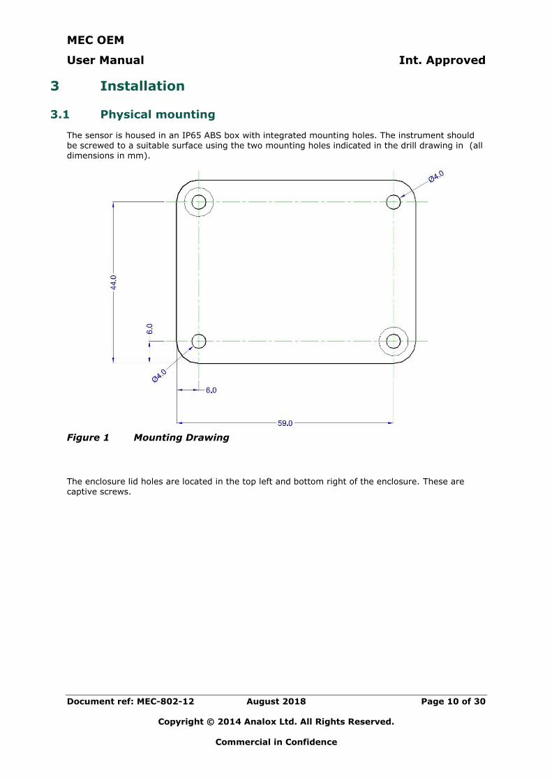
The sensor is housed in an IP65 ABS box with integrated mounting holes. The instrument should be screwed to a suitable surface using the two mounting holes indicated in the drill drawing in (all dimensions in mm).
Figure 1 Mounting Drawing
The enclosure lid holes are located in the top left and bottom right of the enclosure. These are captive screws.
MEC OEM
User Manual Int. Approved
Document ref: MEC-802-12 August 2018 Page 11 of 30
Copyright © 2014 Analox Ltd. All Rights Reserved.
Commercial in Confidence
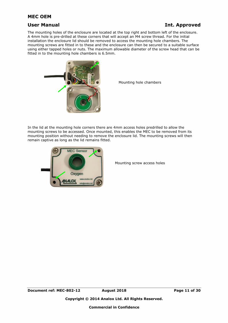
The mounting holes of the enclosure are located at the top right and bottom left of the enclosure.
A 4mm hole is pre-drilled at these corners that will accept an M4 screw thread. For the initial installation the enclosure lid should be removed to access the mounting hole chambers. The mounting screws are fitted in to these and the enclosure can then be secured to a suitable surface using either tapped holes or nuts. The maximum allowable diameter of the screw head that can be fitted in to the mounting hole chambers is 6.5mm.
Mounting hole chambers
In the lid at the mounting hole corners there are 4mm access holes predrilled to allow the mounting screws to be accessed. Once mounted, this enables the MEC to be removed from its mounting position without needing to remove the enclosure lid. The mounting screws will then remain captive as long as the lid remains fitted.
Mounting screw access holes
MEC OEM
User Manual Int. Approved
Document ref: MEC-802-12 August 2018 Page 12 of 30
Copyright © 2014 Analox Ltd. All Rights Reserved.
Commercial in Confidence
3.2 Gas connections
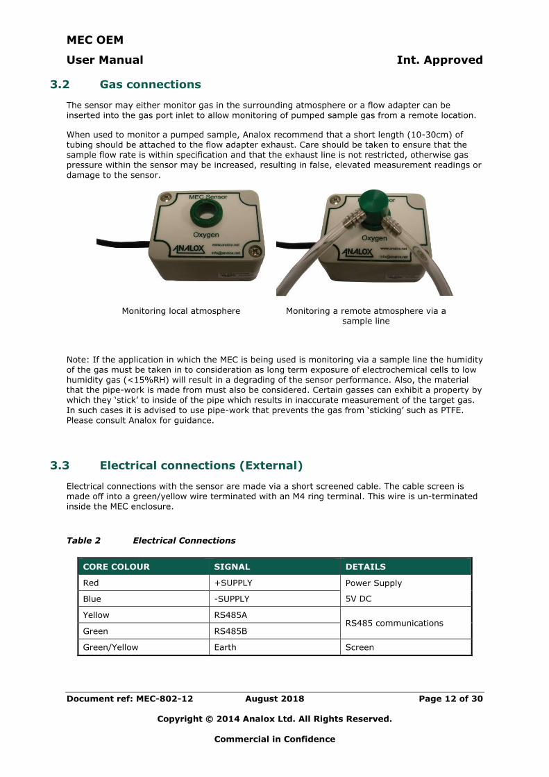
The sensor may either monitor gas in the surrounding atmosphere or a flow adapter can be inserted into the gas port inlet to allow monitoring of pumped sample gas from a remote location.
When used to monitor a pumped sample, Analox recommend that a short length (10-30cm) of tubing should be attached to the flow adapter exhaust. Care should be taken to ensure that the sample flow rate is within specification and that the exhaust line is not restricted, otherwise gas pressure within the sensor may be increased, resulting in false, elevated measurement readings or damage to the sensor.
Monitoring local atmosphere Monitoring a remote atmosphere via a sample line
Note: If the application in which the MEC is being used is monitoring via a sample line the humidity of the gas must be taken in to consideration as long term exposure of electrochemical cells to low humidity gas (<15%RH) will result in a degrading of the sensor performance. Also, the material that the pipe-work is made from must also be considered. Certain gasses can exhibit a property by which they ‘stick’ to inside of the pipe which results in inaccurate measurement of the target gas.
In such cases it is advised to use pipe-work that prevents the gas from ‘sticking’ such as PTFE. Please consult Analox for guidance.
3.3 Electrical connections (External)
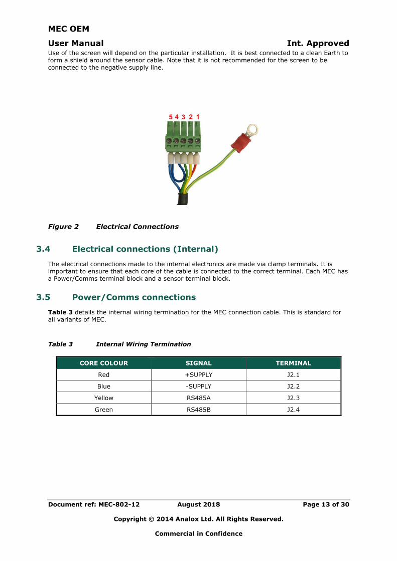
Electrical connections with the sensor are made via a short screened cable. The cable screen is made off into a green/yellow wire terminated with an M4 ring terminal. This wire is un-terminated inside the MEC enclosure.
Table 2 Electrical Connections
CORE COLOUR SIGNAL DETAILS
Red +SUPPLY Power Supply
5V DC Blue -SUPPLY
Yellow RS485A RS485 communications
Green RS485B
Green/Yellow Earth Screen
MEC OEM
User Manual Int. Approved
Document ref: MEC-802-12 August 2018 Page 13 of 30
Copyright © 2014 Analox Ltd. All Rights Reserved.
Commercial in Confidence
Use of the screen will depend on the particular installation. It is best connected to a clean Earth to
form a shield around the sensor cable. Note that it is not recommended for the screen to be connected to the negative supply line.
Figure 2 Electrical Connections
3.4 Electrical connections (Internal)
The electrical connections made to the internal electronics are made via clamp terminals. It is important to ensure that each core of the cable is connected to the correct terminal. Each MEC has a Power/Comms terminal block and a sensor terminal block.
3.5 Power/Comms connections
Table 3 details the internal wiring termination for the MEC connection cable. This is standard for all variants of MEC.
Table 3 Internal Wiring Termination
CORE COLOUR SIGNAL TERMINAL
Red +SUPPLY J2.1
Blue -SUPPLY J2.2
Yellow RS485A J2.3
Green RS485B J2.4

MEC OEM
User Manual Int. Approved
Document ref: MEC-802-12 August 2018 Page 14 of 30
Copyright © 2014 Analox Ltd. All Rights Reserved.
Commercial in Confidence
3.6 4-20mA MEC
The 4-20mA MEC is used to connect a 4-20mA active or passive device to an Analox protocol device (such as an SDA).
For details of how to connect to a 4-20mA MEC, see the quick-start guide supplied with the 4-20mA MEC (MEC-822) or ask Analox for the latest wiring diagram.
3.7 Sensor connections
Table 4 details the internal wiring termination for the MEC sensors. Each MEC variant has a sensor termination that is particular to the type of sensor that is used in that variant.
Table 4 Sensor Connections
MEC VARIANT WIRE COLOUR TERMINAL
Oxygen Red J3.1
Black J3.2
Carbon monoxide Red J3.1
Black J3.2
Yellow J3.3
Hydrogen sulphide
See Carbon monoxide Nitrogen dioxide
Nitric oxide
Sulphur dioxide
Helium Red J3.1
Not connected J3.2
Blue J3.3
Yellow J3.4
4-20mA Red J3.1
Black J3.2
MEC OEM
User Manual Int. Approved
Document ref: MEC-802-12 August 2018 Page 15 of 30
Copyright © 2014 Analox Ltd. All Rights Reserved.
Commercial in Confidence
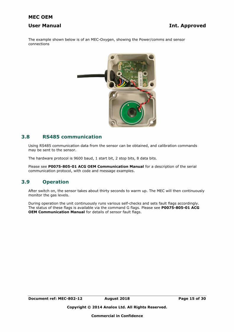
The example shown below is of an MEC-Oxygen, showing the Power/comms and sensor
connections
3.8 RS485 communication
Using RS485 communication data from the sensor can be obtained, and calibration commands may be sent to the sensor.
The hardware protocol is 9600 baud, 1 start bit, 2 stop bits, 8 data bits.
Please see P0075-805-01 ACG OEM Communication Manual for a description of the serial communication protocol, with code and message examples.
3.9 Operation
After switch on, the sensor takes about thirty seconds to warm up. The MEC will then continuously monitor the gas levels.
During operation the unit continuously runs various self-checks and sets fault flags accordingly. The status of these flags is available via the command G flags. Please see P0075-805-01 ACG OEM Communication Manual for details of sensor fault flags.
MEC OEM
User Manual Int. Approved
Document ref: MEC-802-12 August 2018 Page 16 of 30
Copyright © 2014 Analox Ltd. All Rights Reserved.
Commercial in Confidence
4 Sensor replacement
The sensor replacement procedure is specific to the sensor type that is used for that particular variant of MEC. The following sections detail the procedure for replacement of the different sensor types used.
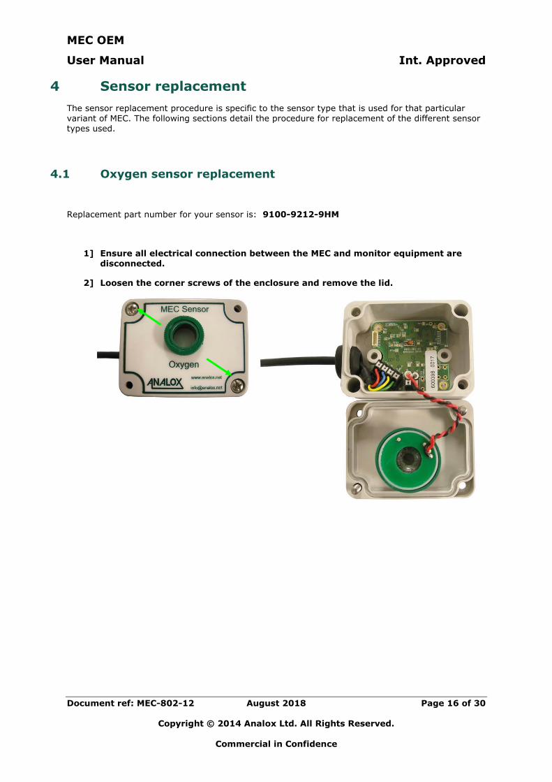
4.1 Oxygen sensor replacement
Replacement part number for your sensor is: 9100-9212-9HM
1] Ensure all electrical connection between the MEC and monitor equipment are disconnected.
2] Loosen the corner screws of the enclosure and remove the lid.
MEC OEM
User Manual Int. Approved
Document ref: MEC-802-12 August 2018 Page 17 of 30
Copyright © 2014 Analox Ltd. All Rights Reserved.
Commercial in Confidence
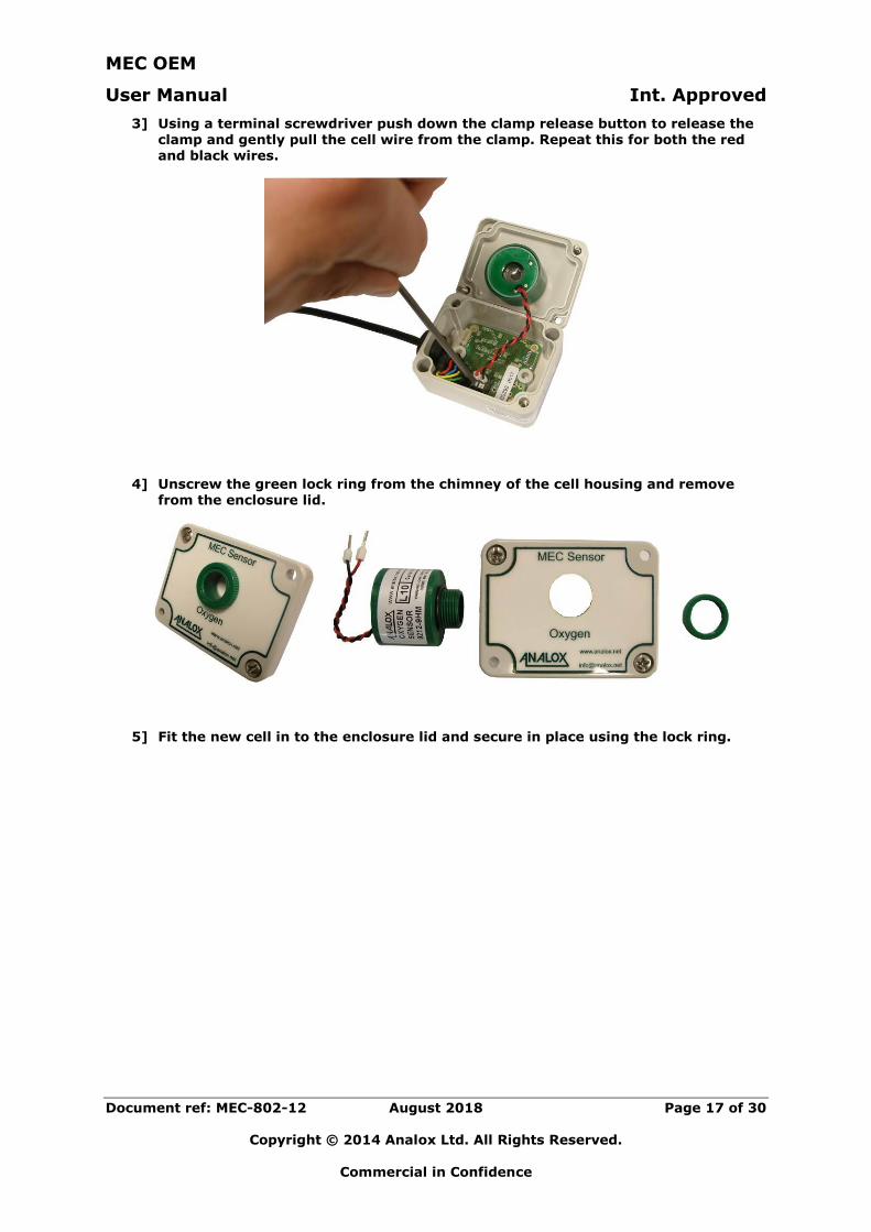
3] Using a terminal screwdriver push down the clamp release button to release the
clamp and gently pull the cell wire from the clamp. Repeat this for both the red and black wires.
4] Unscrew the green lock ring from the chimney of the cell housing and remove from the enclosure lid.
5] Fit the new cell in to the enclosure lid and secure in place using the lock ring.
MEC OEM
User Manual Int. Approved
Document ref: MEC-802-12 August 2018 Page 18 of 30
Copyright © 2014 Analox Ltd. All Rights Reserved.
Commercial in Confidence
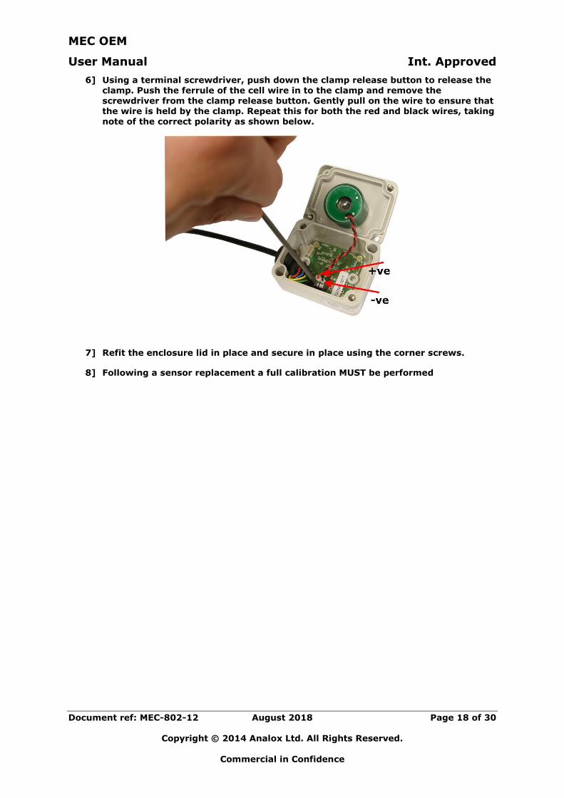
6] Using a terminal screwdriver, push down the clamp release button to release the
clamp. Push the ferrule of the cell wire in to the clamp and remove the screwdriver from the clamp release button. Gently pull on the wire to ensure that the wire is held by the clamp. Repeat this for both the red and black wires, taking note of the correct polarity as shown below.
7] Refit the enclosure lid in place and secure in place using the corner screws.
8] Following a sensor replacement a full calibration MUST be performed
MEC OEM
User Manual Int. Approved
Document ref: MEC-802-12 August 2018 Page 19 of 30
Copyright © 2014 Analox Ltd. All Rights Reserved.
Commercial in Confidence
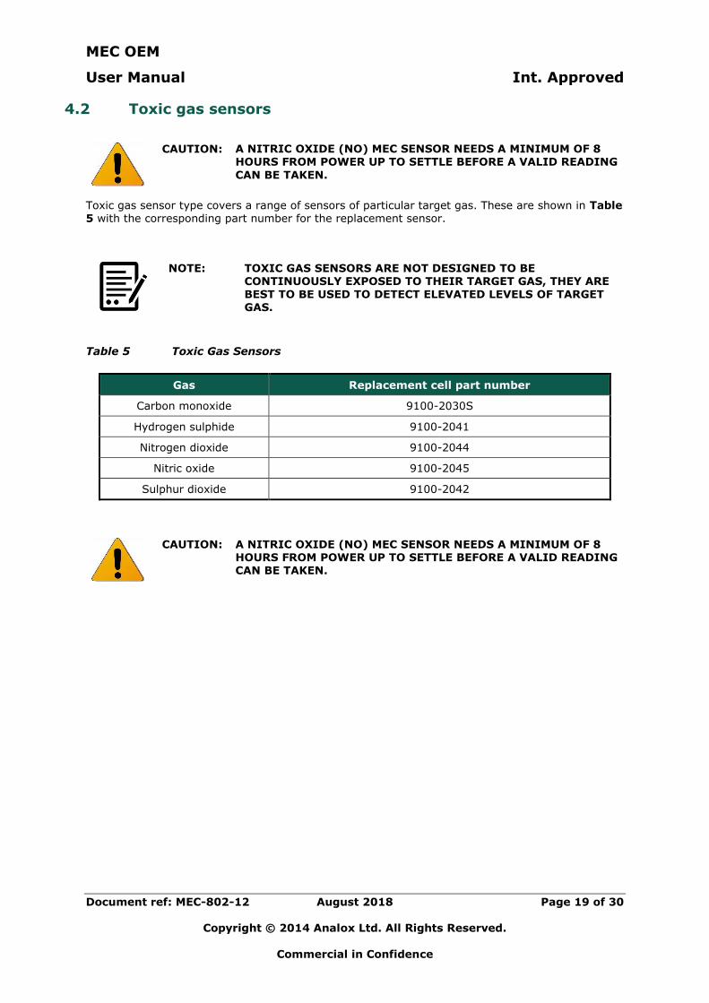
4.2 Toxic gas sensors
CAUTION: A NITRIC OXIDE (NO) MEC SENSOR NEEDS A MINIMUM OF 8 HOURS FROM POWER UP TO SETTLE BEFORE A VALID READING
CAN BE TAKEN.
Toxic gas sensor type covers a range of sensors of particular target gas. These are shown in Table 5 with the corresponding part number for the replacement sensor.
NOTE: TOXIC GAS SENSORS ARE NOT DESIGNED TO BE CONTINUOUSLY EXPOSED TO THEIR TARGET GAS, THEY ARE BEST TO BE USED TO DETECT ELEVATED LEVELS OF TARGET GAS.
Table 5 Toxic Gas Sensors
Gas Replacement cell part number
Carbon monoxide 9100-2030S
Hydrogen sulphide 9100-2041
Nitrogen dioxide 9100-2044
Nitric oxide 9100-2045
Sulphur dioxide 9100-2042
CAUTION: A NITRIC OXIDE (NO) MEC SENSOR NEEDS A MINIMUM OF 8 HOURS FROM POWER UP TO SETTLE BEFORE A VALID READING CAN BE TAKEN.
MEC OEM
User Manual Int. Approved
Document ref: MEC-802-12 August 2018 Page 20 of 30
Copyright © 2014 Analox Ltd. All Rights Reserved.
Commercial in Confidence
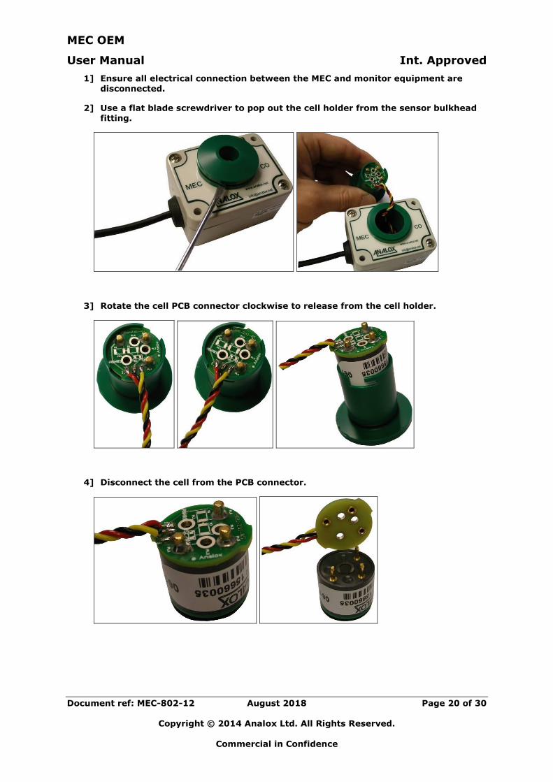
1] Ensure all electrical connection between the MEC and monitor equipment are
disconnected.
2] Use a flat blade screwdriver to pop out the cell holder from the sensor bulkhead fitting.
3] Rotate the cell PCB connector clockwise to release from the cell holder.
4] Disconnect the cell from the PCB connector.
MEC OEM
User Manual Int. Approved
Document ref: MEC-802-12 August 2018 Page 21 of 30
Copyright © 2014 Analox Ltd. All Rights Reserved.
Commercial in Confidence
5] Connect the new cell to the PCB connector (Note that it will only connect in one orientation).
6] Fit the cell in to the housing in the reverse action of step 3]
7] Refit the cell holder in to the sensor bulkhead.
8] Following a sensor replacement a full calibration MUST be performed.
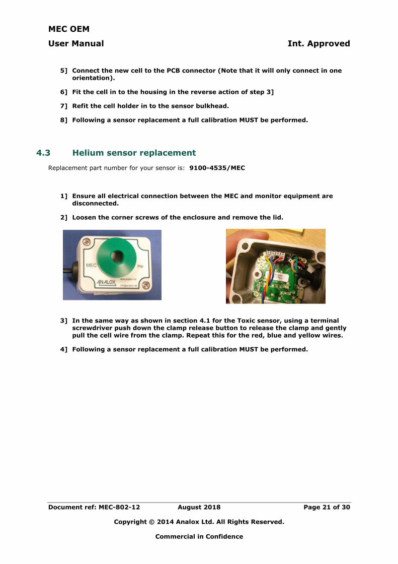
4.3 Helium sensor replacement
Replacement part number for your sensor is: 9100-4535/MEC
1] Ensure all electrical connection between the MEC and monitor equipment are disconnected.
2] Loosen the corner screws of the enclosure and remove the lid.
3] In the same way as shown in section 4.1 for the Toxic sensor, using a terminal screwdriver push down the clamp release button to release the clamp and gently
pull the cell wire from the clamp. Repeat this for the red, blue and yellow wires.
4] Following a sensor replacement a full calibration MUST be performed.
MEC OEM
User Manual Int. Approved
Document ref: MEC-802-12 August 2018 Page 22 of 30
Copyright © 2014 Analox Ltd. All Rights Reserved.
Commercial in Confidence
5 Calibration
Whilst in use, an MEC sensor should be periodically calibrated at intervals deemed necessary for the monitoring application by exposing the sensor to gas of a known concentration. Calibration adjustments of the sensor’s output can be made where necessary as follows.
Each sensor’s output is defined by two calibration points, one low and one high. To perform a successful calibration adjustment, both low and high calibration points should be adjusted.
NOTE: THE HIGH AND LOW CALIBRATIONS PERFORMED ON A SENSOR SHOULD BE SELECTED APPROPRIATELY. AN MEC DOES NOT REQUIRE THAT THE LOW CALIBRATION IS A TRUE ZERO CALIBRATION (I.E. ZERO CONCENTRATION OF THE
TARGET GAS), BUT FOR GREATEST ACCURACY ACROSS THE WHOLE SENSOR RANGE IT IS RECOMMENDED THAT A GAS WITH A KNOWN ZERO CONCENTRATION OF THE TARGET GAS
IS USED.
No additional calibration should be required for the 4-20mA MEC.
See section 6 for list the recommended calibration gasses for all MEC variants.
MEC OEM
User Manual Int. Approved
Document ref: MEC-802-12 August 2018 Page 23 of 30
Copyright © 2014 Analox Ltd. All Rights Reserved.
Commercial in Confidence
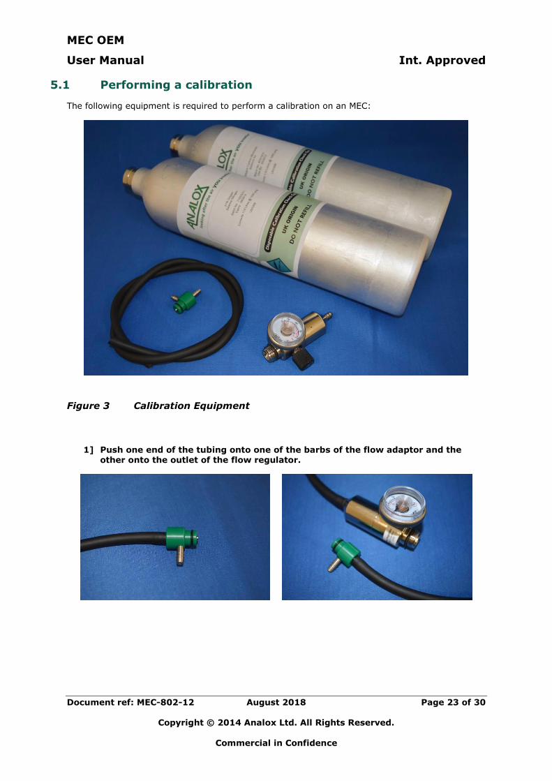
5.1 Performing a calibration
The following equipment is required to perform a calibration on an MEC:
Figure 3 Calibration Equipment
1] Push one end of the tubing onto one of the barbs of the flow adaptor and the other onto the outlet of the flow regulator.
MEC OEM
User Manual Int. Approved
Document ref: MEC-802-12 August 2018 Page 24 of 30
Copyright © 2014 Analox Ltd. All Rights Reserved.
Commercial in Confidence
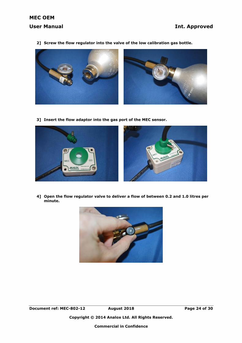
2] Screw the flow regulator into the valve of the low calibration gas bottle.
3] Insert the flow adaptor into the gas port of the MEC sensor.
4] Open the flow regulator valve to deliver a flow of between 0.2 and 1.0 litres per minute.
MEC OEM
User Manual Int. Approved
Document ref: MEC-802-12 August 2018 Page 25 of 30
Copyright © 2014 Analox Ltd. All Rights Reserved.
Commercial in Confidence
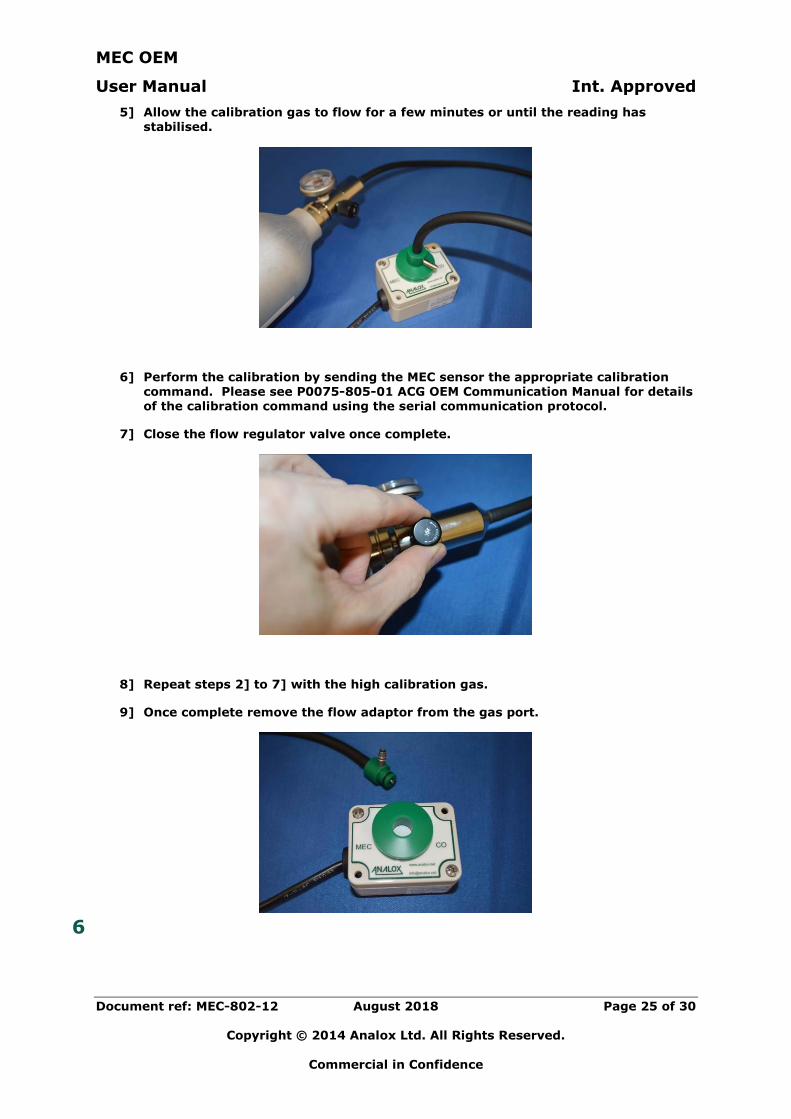
5] Allow the calibration gas to flow for a few minutes or until the reading has
stabilised.
6] Perform the calibration by sending the MEC sensor the appropriate calibration command. Please see P0075-805-01 ACG OEM Communication Manual for details of the calibration command using the serial communication protocol.
7] Close the flow regulator valve once complete.
8] Repeat steps 2] to 7] with the high calibration gas.
9] Once complete remove the flow adaptor from the gas port.
6
MEC OEM
User Manual Int. Approved
Document ref: MEC-802-12 August 2018 Page 26 of 30
Copyright © 2014 Analox Ltd. All Rights Reserved.
Commercial in Confidence
6 Spares and Accessories
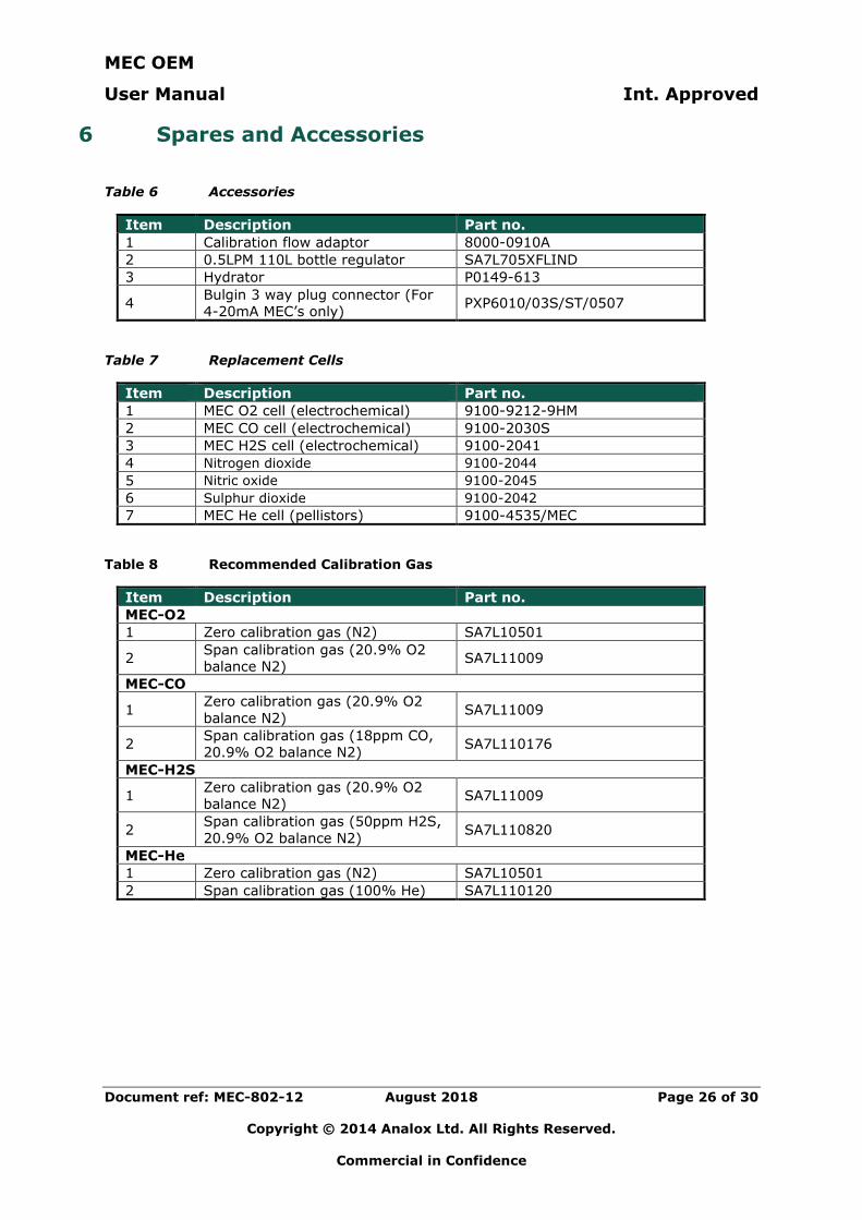
Table 6 Accessories
Item Description Part no.
1 Calibration flow adaptor 8000-0910A
2 0.5LPM 110L bottle regulator SA7L705XFLIND
3 Hydrator P0149-613
4 Bulgin 3 way plug connector (For
4-20mA MEC’s only) PXP6010/03S/ST/0507
Table 7 Replacement Cells
Item Description Part no.
1 MEC O2 cell (electrochemical) 9100-9212-9HM
2 MEC CO cell (electrochemical) 9100-2030S
3 MEC H2S cell (electrochemical) 9100-2041
4 Nitrogen dioxide 9100-2044
5 Nitric oxide 9100-2045
6 Sulphur dioxide 9100-2042
7 MEC He cell (pellistors) 9100-4535/MEC
Table 8 Recommended Calibration Gas
Item Description Part no.
MEC-O2
1 Zero calibration gas (N2) SA7L10501
2 Span calibration gas (20.9% O2
balance N2) SA7L11009
MEC-CO
1 Zero calibration gas (20.9% O2
balance N2) SA7L11009
2 Span calibration gas (18ppm CO,
20.9% O2 balance N2) SA7L110176
MEC-H2S
1 Zero calibration gas (20.9% O2
balance N2) SA7L11009
2 Span calibration gas (50ppm H2S,
20.9% O2 balance N2) SA7L110820
MEC-He
1 Zero calibration gas (N2) SA7L10501
2 Span calibration gas (100% He) SA7L110120
MEC OEM
User Manual Int. Approved
Document ref: MEC-802-12 August 2018 Page 27 of 30
Copyright © 2014 Analox Ltd. All Rights Reserved.
Commercial in Confidence
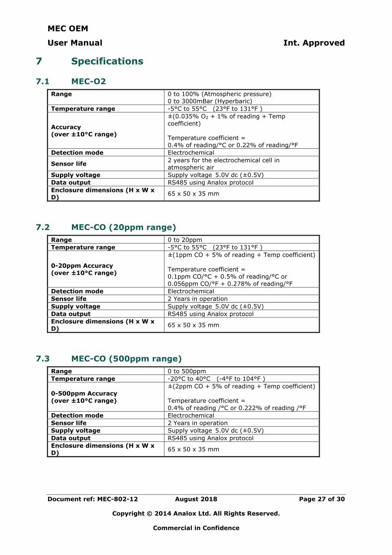
7 Specifications
7.1 MEC-O2
Range
0 to 100% (Atmospheric pressure) 0 to 3000mBar (Hyperbaric)
Temperature range -5°C to 55°C (23°F to 131°F )
Accuracy (over ±10°C range)
±(0.035% O2 + 1% of reading + Temp coefficient) Temperature coefficient = 0.4% of reading/°C or 0.22% of reading/°F
Detection mode Electrochemical
Sensor life 2 years for the electrochemical cell in atmospheric air
Supply voltage Supply voltage 5.0V dc (±0.5V)
Data output RS485 using Analox protocol
Enclosure dimensions (H x W x D)
65 x 50 x 35 mm
7.2 MEC-CO (20ppm range)
Range 0 to 20ppm
Temperature range -5°C to 55°C (23°F to 131°F )
0-20ppm Accuracy (over ±10°C range)
±(1ppm CO + 5% of reading + Temp coefficient)
Temperature coefficient = 0.1ppm CO/°C + 0.5% of reading/°C or 0.056ppm CO/°F + 0.278% of reading/°F
Detection mode Electrochemical
Sensor life 2 Years in operation
Supply voltage Supply voltage 5.0V dc (±0.5V)
Data output RS485 using Analox protocol
Enclosure dimensions (H x W x D)
65 x 50 x 35 mm
7.3 MEC-CO (500ppm range)
Range 0 to 500ppm
Temperature range -20°C to 40°C (-4°F to 104°F )
0-500ppm Accuracy (over ±10°C range)
±(2ppm CO + 5% of reading + Temp coefficient) Temperature coefficient =
0.4% of reading /°C or 0.222% of reading /°F
Detection mode Electrochemical
Sensor life 2 Years in operation
Supply voltage Supply voltage 5.0V dc (±0.5V)
Data output RS485 using Analox protocol
Enclosure dimensions (H x W x D)
65 x 50 x 35 mm
MEC OEM
User Manual Int. Approved
Document ref: MEC-802-12 August 2018 Page 28 of 30
Copyright © 2014 Analox Ltd. All Rights Reserved.
Commercial in Confidence
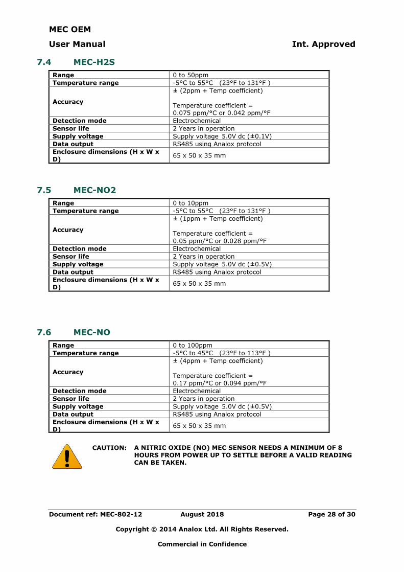
7.4 MEC-H2S
Range 0 to 50ppm
Temperature range -5°C to 55°C (23°F to 131°F )
Accuracy
± (2ppm + Temp coefficient) Temperature coefficient = 0.075 ppm/°C or 0.042 ppm/°F
Detection mode Electrochemical
Sensor life 2 Years in operation
Supply voltage Supply voltage 5.0V dc (±0.1V)
Data output RS485 using Analox protocol
Enclosure dimensions (H x W x
D) 65 x 50 x 35 mm
7.5 MEC-NO2
Range 0 to 10ppm
Temperature range -5°C to 55°C (23°F to 131°F )
Accuracy
± (1ppm + Temp coefficient) Temperature coefficient =
0.05 ppm/°C or 0.028 ppm/°F
Detection mode Electrochemical
Sensor life 2 Years in operation
Supply voltage Supply voltage 5.0V dc (±0.5V)
Data output RS485 using Analox protocol
Enclosure dimensions (H x W x D)
65 x 50 x 35 mm
7.6 MEC-NO
Range 0 to 100ppm
Temperature range -5°C to 45°C (23°F to 113°F )
Accuracy
± (4ppm + Temp coefficient)
Temperature coefficient = 0.17 ppm/°C or 0.094 ppm/°F
Detection mode Electrochemical
Sensor life 2 Years in operation
Supply voltage Supply voltage 5.0V dc (±0.5V)
Data output RS485 using Analox protocol
Enclosure dimensions (H x W x D)
65 x 50 x 35 mm
CAUTION: A NITRIC OXIDE (NO) MEC SENSOR NEEDS A MINIMUM OF 8 HOURS FROM POWER UP TO SETTLE BEFORE A VALID READING CAN BE TAKEN.
MEC OEM
User Manual Int. Approved
Document ref: MEC-802-12 August 2018 Page 29 of 30
Copyright © 2014 Analox Ltd. All Rights Reserved.
Commercial in Confidence
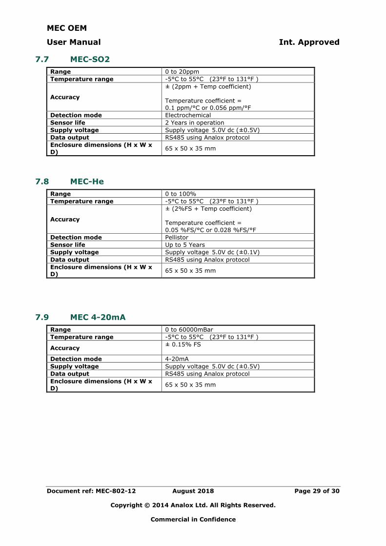
7.7 MEC-SO2
Range 0 to 20ppm
Temperature range -5°C to 55°C (23°F to 131°F )
Accuracy
± (2ppm + Temp coefficient) Temperature coefficient = 0.1 ppm/°C or 0.056 ppm/°F
Detection mode Electrochemical
Sensor life 2 Years in operation
Supply voltage Supply voltage 5.0V dc (±0.5V)
Data output RS485 using Analox protocol
Enclosure dimensions (H x W x
D) 65 x 50 x 35 mm
7.8 MEC-He
Range 0 to 100%
Temperature range -5°C to 55°C (23°F to 131°F )
Accuracy
± (2%FS + Temp coefficient) Temperature coefficient =
0.05 %FS/°C or 0.028 %FS/°F
Detection mode Pellistor
Sensor life Up to 5 Years
Supply voltage Supply voltage 5.0V dc (±0.1V)
Data output RS485 using Analox protocol
Enclosure dimensions (H x W x D)
65 x 50 x 35 mm
7.9 MEC 4-20mA
Range 0 to 60000mBar
Temperature range -5°C to 55°C (23°F to 131°F )
Accuracy ± 0.15% FS
Detection mode 4-20mA
Supply voltage Supply voltage 5.0V dc (±0.5V)
Data output RS485 using Analox protocol
Enclosure dimensions (H x W x D)
65 x 50 x 35 mm
MEC OEM
User Manual Int. Approved
Document ref: MEC-802-12 August 2018 Page 30 of 30
Copyright © 2014 Analox Ltd. All Rights Reserved.
Commercial in Confidence
8 General care and disposal
Although designed to be water resistant the MEC should not be intentionally immersed in liquid or left outside unprotected.
To clean the MEC use a damp soft cloth.
According to WEEE regulation this electronic product cannot be placed in household waste bins. Please check local regulations for information on the disposal of electronic products in your area.