combustion in si and ci engines
TRANSCRIPT

www.iitk.ac.in/erl
IIT Kanpur
Energy Systems-I
Course InstructorDr. Avinash Kumar Agarwal
Professor Department of Mechanical Engineering
Indian Institute of Technology Kanpur, Kanpur
Course: ME301
Combustion in SI and CI Engines
Lecture-13

Lecture-13 Energy Systems-I22
Lecture Objectives
Combustion in SI Engines
Introduction and working of SI Engine
Flammability limits
Ignition System in SI Engines
Stages of Combustion in SI Engines
Effect of Engine Variables on Ignition Lag and Flame speed
Numerical Problem
Combustion in CI Engines
History of Diesel Engine
Diesel Cycle
Types of CI Engines
Flame Formation
Combustion Visualization
Lecture-13 Energy Systems-I3
Introduction to SI Engine
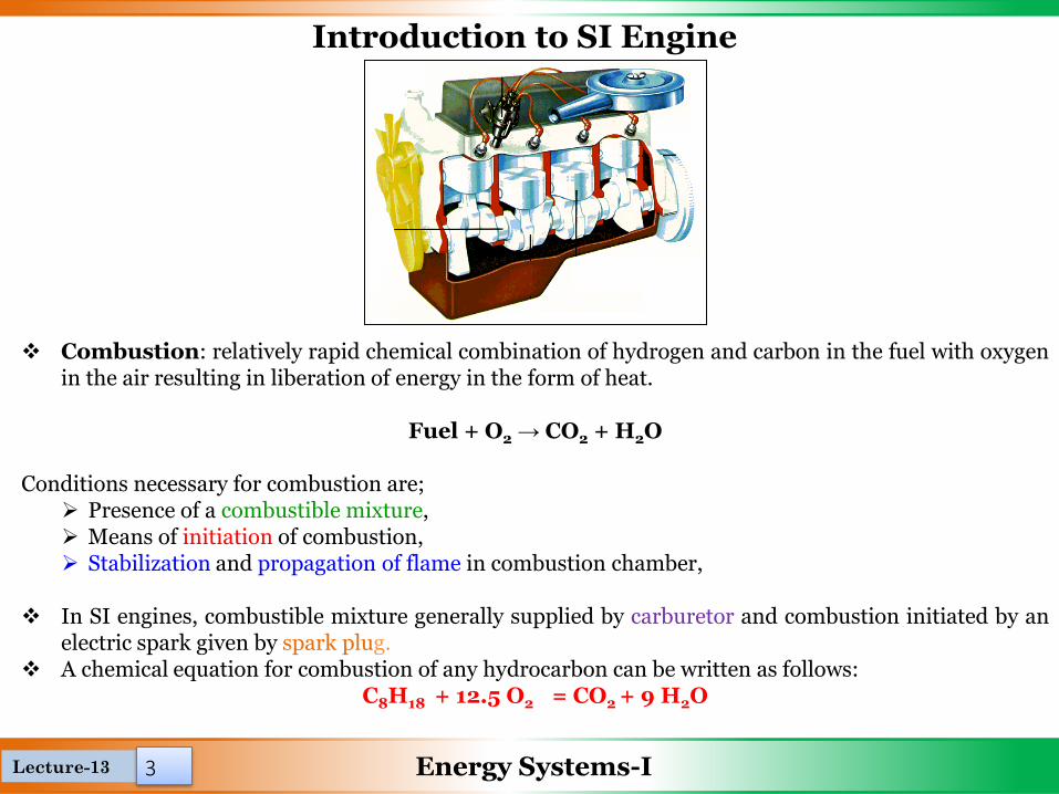
❖ Combustion: relatively rapid chemical combination of hydrogen and carbon in the fuel with oxygenin the air resulting in liberation of energy in the form of heat.
Fuel + O2 → CO2 + H2O
Conditions necessary for combustion are;➢ Presence of a combustible mixture,➢ Means of initiation of combustion,➢ Stabilization and propagation of flame in combustion chamber,
❖ In SI engines, combustible mixture generally supplied by carburetor and combustion initiated by anelectric spark given by spark plug.
❖ A chemical equation for combustion of any hydrocarbon can be written as follows:C8H18 + 12.5 O2 = CO2 + 9 H2O

Lecture-13 Energy Systems-I4
Working of SI Engine
❖ In spark-ignition engine, fuel and air mixed together in intake system outside engine cylinder.
❖ Air-fuel vapors inducted through intake valve into the cylinder.
❖ Where it is mixed with residual gas, and then compression take place.
❖ Under normal operating conditions, combustion is initiated towards the end of the compression
stroke at the spark plug by an electric discharge.
❖ A turbulent flame develops, propagates through this premixed fuel, air, burned gas mixture until
it reaches the combustion chamber walls, and then extinguishes.
❖ In SI engine compression ratio is about 8 to 10.

Lecture-13 Energy Systems-I5
Ignition Limits
❖ Ignition of the charge is only possible within certain limits of air-fuel ratio.
❖ For hydrocarbon fuel the stoichiometric air-fuel ratio is about 15:1.
❖ Ignition limit for hydrocarbon fuel is must lie between 7:1 to 30:1.
❖ The lower and upper ignition limits of the mixture depend upon mixture ratio and temperature.
❖ The ignition limits are wider at increased temperatures because of higher rates of reaction and higher
thermal diffusivity coefficients of the mixture.

Lecture-13 Energy Systems-I6
Spark Plug
• For spark to jump across air gap of 0.6 mm in engine
cylinder (compression ratio= 8:1) approx. 8 kV required.
• Ignition system transforms battery voltage of 12 V to 8-20
kV to deliver voltage to right cylinder at right time.
• About 0.2 mJ of energy required to ignite stoichiometric
mixture at normal engine operating conditions by spark.
Over 3 mJ required for rich or lean mixture.
• In general, ignition systems deliver 30 to 50 mJ of electrical
energy to spark.
• Fundamental requirements of ignition source:
❑ A high ignition voltage to break down in the spark-gap,
❑ A low source impedance or steep voltage rise,
❑ A high energy capacity to create a spark kernel of
sufficient size,
❑ Sufficient duration of the voltage pulse to ensure ignition

Lecture-13 Energy Systems-I7
Ignition System in SI Engines
Improvement of spark ignition effectiveness
1. Energy of spark generated by spark-plug is in range of 50-100 mJ,
enough for ignition of stoichiometric mixture, not enough for lean
mixtures.
2. To improve effectiveness of spark ignition of lean mixtures a few
modifications of SI engines ignition systems have been proposed:
➢ 2- spark-plug systems (twin-spark),
➢ Increase of ignition energy by:
• Increase of spark energy,
• Laser ignition
➢ Increase the distance between electrodes
When the mixture could be ignited?
✓ Spark energy must be higher than minimum energy of ignition of mixture,
✓ Distance between electrodes is larger than extinguishing distance for given mixture,
✓ Local gradient of velocity is smaller than critical for given mixture.

Lecture-13 Energy Systems-I8
Spark and Flame Propagation
▪ Spark discharge at -30˚ & flame visible first at -24˚.
▪ Nearly circular flame propagates outward from spark plug location.
▪ Irregular shape of turbulent flame front

Lecture-13 Energy Systems-I9
Spark and Flame Propagation
▪ Blue light is emitted most strongly from flame front.
▪ At TC, flame diameter ≈2/3 of cylinder bore.
▪ Flame reaches farthest cylinder wall at 15˚ ATC, but combustion continues for another 10˚.
▪ At about 10o ATC, additional radiation - initially white, turning to pinky-orange – centered at spark
plug location evident.
▪ These afterglow comes from gases behind flame as these are compressed to highest temperatures
attained in cylinder (at about 15o ATC) while rest of charge burns.
Lecture-13 Energy Systems-I10
Stages of Combustion in SI Engines
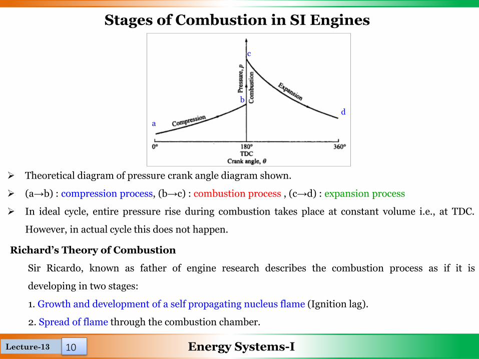
➢ Theoretical diagram of pressure crank angle diagram shown.
➢ (a→b) : compression process, (b→c) : combustion process , (c→d) : expansion process
➢ In ideal cycle, entire pressure rise during combustion takes place at constant volume i.e., at TDC.
However, in actual cycle this does not happen.
Richard’s Theory of Combustion
Sir Ricardo, known as father of engine research describes the combustion process as if it is
developing in two stages:
1. Growth and development of a self propagating nucleus flame (Ignition lag).
2. Spread of flame through the combustion chamber.
a
b
c
d
Lecture-13 Energy Systems-I11
Stages of Combustion in SI Engines
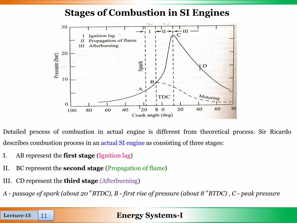
Detailed process of combustion in actual engine is different from theoretical process. Sir Ricardo
describes combustion process in an actual SI engine as consisting of three stages:
I. AB represent the first stage (Ignition lag)
II. BC represent the second stage (Propagation of flame)
III. CD represent the third stage (Afterburning)
A - passage of spark (about 20° BTDC), B - first rise of pressure (about 8° BTDC) , C - peak pressure

Lecture-13 Energy Systems-I12
Stages of Combustion in SI Engines
Ignition Lag
➢ Certain time interval between spark and noticeable rise in pressure due to combustion. This time lag
is called Ignition Lag.
➢ Time interval in which molecules get heated up to self ignition temperature , get ignited and produce
self propagating nucleus of flame.
➢ Ignition lag is very small and lies between 0.00015 to 0.0002 seconds. An ignition lag of 0.002
seconds corresponds to 35 deg crank rotation when engine is running at 3000 RPM.
➢ This is a chemical process depending upon the nature of fuel, temperature and pressure, proportions
of exhaust gas and rate of oxidation or burning.
Propagation of flame
➢ Once flame is formed, it should be self sustained and must be able to propagate through the mixture.
Possible when rate of heat generation by burning is greater than heat lost by flame to surrounding.
Lecture-13 Energy Systems-I13
Stages of Combustion in SI Engines
Starting point of second stage is where first measurable rise of pressure can be seen on indicator
diagram.
This stage is also called main stage as about 87% energy evolved in this stage.
Afterburning
Combustion does not terminate at this point and afterburning continues for long time near walls and
behind turbulent flame front.
The combustion rate in this stage reduces due to surface of the flame front becoming smaller and
reduction in turbulence.
About 10% or more heat is evolved in after-burning stage.
Lecture-13 Energy Systems-I14
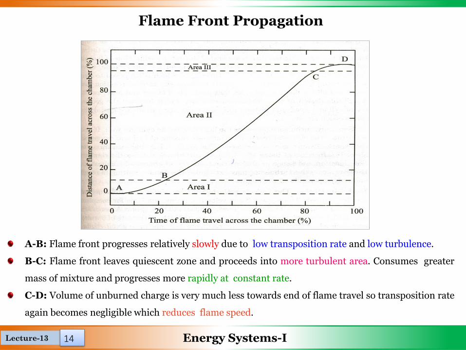
Flame Front Propagation
A-B: Flame front progresses relatively slowly due to low transposition rate and low turbulence.
B-C: Flame front leaves quiescent zone and proceeds into more turbulent area. Consumes greater
mass of mixture and progresses more rapidly at constant rate.
C-D: Volume of unburned charge is very much less towards end of flame travel so transposition rate
again becomes negligible which reduces flame speed.

Lecture-13 Energy Systems-I1515
The factors which affect the flame propagations are:
✓ In-cylinder temperature and pressure
✓ Air fuel ratio
✓ Compression ratio
✓ Engine Load
✓ Turbulence and engine speed
✓ Engine size
Rate of flame propagation affects combustion process in SI engines.
Higher combustion efficiency and fuel economy can be achieved by higher flame propagation
velocities.
Unfortunately flame velocities for most of fuel range between 10 to 30 m/second.
Flame Front Propagation

Lecture-13 Energy Systems-I16
Effect of Engine Variables on Ignition Lag
Mixture ratio
▪ The ignition lag is smallest for mixture ratio which gives
the maximum temperature. This ratio is somewhat richer
than stoichiometric ratio.
Electrode gap
▪ If gap is too small, quenching of flame nucleus may occur
but if it is too large, spark intensity reduced . Lower the
compression ratio higher the electrode gap required.
First phase of combustion is called ignition lag. This time is normally about 0.0015 seconds and
crank angle is 10 to 20 degrees.
Nature of Fuel
▪ The ignition lag depends on the chemical nature of the fuel.
▪ The higher the self-ignition temperature of the fuel, the longer the ignition lag.
Lecture-13 Energy Systems-I17
Effect of Engine Variables on Ignition Lag
Initial temperature and pressure
▪ Increasing the intake temperature and pressure, increasing compression ratio and retarding spark,
these all reduce the ignition lag.
Turbulence
▪ Excessive turbulence of mixture in area of spark plug is harmful. Since it increases heat transfer from
combustion zone and leads to unstable development of nucleus of flame.
▪ Turbulence increases heat flow to cylindrical wall. It also accelerates chemical reaction by intimate
mixing of fuel and oxygen so that spark advance may be reduced.
▪ This helps in burning lean mixture also. Increase of flame speed due to turbulence reduces
combustion duration and hence minimizes tendency of abnormal combustion.
▪ However, excessive turbulence may extinguish flame resulting in rough and noisy operation of the
engine.
Lecture-13 Energy Systems-I18
Factors influencing the Flame Speed
Temperature and Pressure
▪ Flame speed increases with increase in intake temperature and pressure.
▪ A higher initial pressure and temperature may help to form better homogeneous mixture which helps
in increasing flame speed. This is possible because of overall increase in density of charge.
Engine Speed
▪ The flame speed increases almost linearly with engine speed.
▪ Since increase in engine speed increases turbulence inside cylinder.
Fuel-Air Ratio
▪ Fuel-air ratio has very significant influence on flame speed.
▪ Highest flame velocities (minimum time for complete combustion) are obtained with somewhat
richer mixture ( point A) as shown in fig.

Lecture-13 Energy Systems-I19
Factors influencing the Flame Speed
▪ When mixture made leaner or richer, flame speed decreases.
▪ Less thermal energy released in case of lean mixtures resulting in lower flame temperature.
▪ Very rich mixtures lead to incomplete combustion which results in release of less thermal energy.
Engine Output
▪ Cycle pressure increases when engine output increased. With increased throttle opening, cylinder
gets filled to higher density. Flame speed increases.

Lecture-13 Energy Systems-I20
Factors influencing the Flame Speed
Compression Ratio
▪ Higher compression ratio increases pressure and temperature of working mixture which reduces
initial preparation phase of combustion, hence less ignition advance needed.
▪ Thus engines having higher compression ratios have higher flame speeds.
Engine Size
▪ Size of engine does not have much effect on rate of flame propagation.
▪ In large engines, time required for complete combustion is more because flame travels longer
distance.
▪ Requires increased crank angle duration during combustion.
▪ This is one of the reasons why large sized engines are designed to operate at low speeds.

Lecture-13 Energy Systems-I2121
Q-1 Find the stoichiometric A/F ratio for the combustion of ethyl-alcohol (C2H5OH) in a petrol engine.
Solution --
Numerical Problem

Lecture-15 Energy Systems-I 22 22
Combustion in CI Engines

Lecture-14 Energy Systems-I
History of Diesel Engine
➢ Rudolf Diesel developed the idea for the diesel engine and obtained the German patent for it in 1892.
➢ His goal was to create an engine with high efficiency.
➢ Gasoline engines had been invented in 1876 and especially at that time, were not very efficient.
➢ Both the gasoline and diesel engine utilize the process of internal combustion for power.
➢ Diesel engines use the heat of compressed air to ignite the fuel (intakes air, compresses it, then injects
fuel).
23

Lecture-14 Energy Systems-I
Diesel Cycle
24

Lecture-14 Energy Systems-I
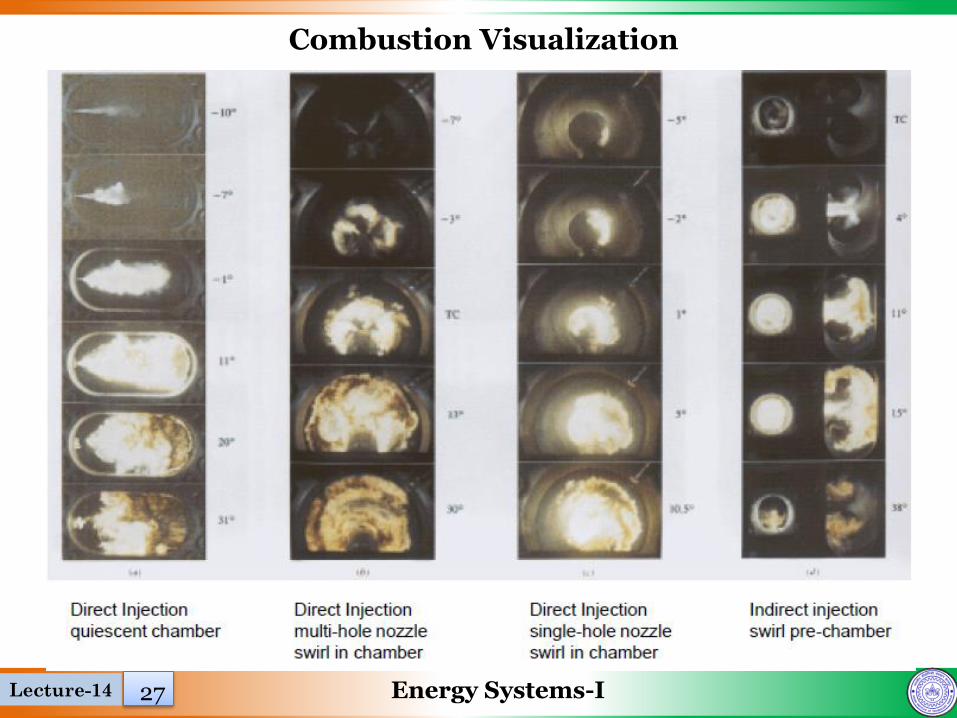
Types of CI Engines
➢ Direct-injection – have a single open combustion chamber into which fuel is injected directly ➢ Indirect-injection – chamber is divided into two regions and the fuel is injected into the “pre-
chamber” which is connected to the main chamber via a nozzle, or one or more orifices.
25

Lecture-14 Energy Systems-I
Spray Formation
Pilot Injection Main Injection
26
Lecture-14 Energy Systems-I
Combustion Visualization
27
Lecture-14 Energy Systems-I28
Lecture Objectives
Combustion in SI Engines
Introduction and working of SI Engine
Flammability limits
Ignition System in SI Engines
Stages of Combustion in SI Engines
Effect of Engine Variables on Ignition Lag and Flame speed
Numerical Problem
Combustion in CI Engines
History of Diesel Engine
Diesel Cycle
Types of CI Engines
Flame Formation
Combustion Visualization

Energy Systems-I