syllabus : ic engines unit-iii : compression ignition (ci) engines (5) fuel supply system, types of...
TRANSCRIPT
Unit III
CI Engines

Syllabus : IC Engines
UNIT-III : COMPRESSION IGNITION (CI) ENGINES (5)Fuel supply system, types of fuel pump, injector and distribution system, combustion in compression ignition engines, stages of combustion, factors affecting combustion, phenomenon of knocking in CI engine, effect of knocking, methods of knock control, types of combustion chambers, rating of fuels in CI engines, dopes & additives, comparison of knocking in SI & CI engines.
Lecture No 17
Learning Objectives: • To understand fuel supply system for CI engine • To learn various types of fuel pumps
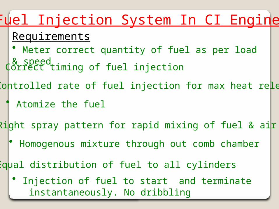
Fuel Injection System In CI EnginesRequirements• Meter correct quantity of fuel as per load & speed
• Correct timing of fuel injection
• Controlled rate of fuel injection for max heat release
• Atomize the fuel
• Right spray pattern for rapid mixing of fuel & air
• Homogenous mixture through out comb chamber
• Equal distribution of fuel to all cylinders
• Injection of fuel to start and terminate instantaneously. No dribbling
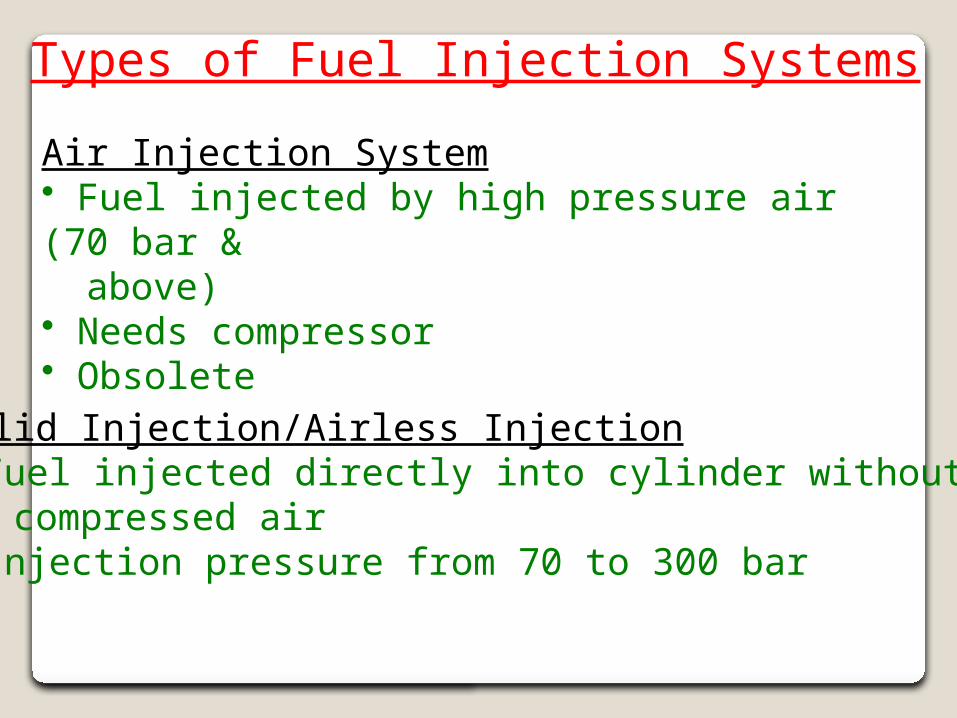
Types of Fuel Injection Systems
Air Injection System• Fuel injected by high pressure air (70 bar & above)• Needs compressor• Obsolete
Solid Injection/Airless Injection• Fuel injected directly into cylinder without compressed air• Injection pressure from 70 to 300 bar
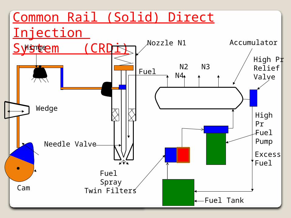
Common Rail (Solid) Direct Injection System (CRDi)
Nozzle N1
N2 N3 N4
Cam
Wedge
Hinge
Needle Valve
Fuel Spray
Fuel
Accumulator
High PrReliefValve
High Pr Fuel Pump
Fuel TankTwin Filters
ExcessFuel

CRDi NEW Photo
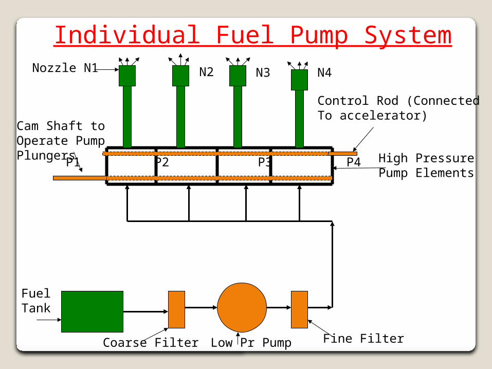
Fuel Tank
Coarse Filter Fine FilterLow Pr Pump
P1 P2 P3 P4 High PressurePump Elements
Nozzle N1 N2 N3 N4
Control Rod (ConnectedTo accelerator)
Cam Shaft toOperate PumpPlungers
Individual Fuel Pump System
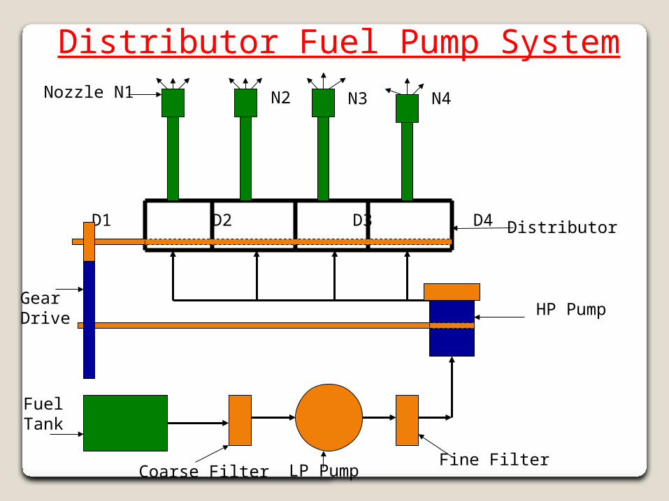
Fuel Tank
Coarse FilterFine Filter
LP Pump
D1 D2 D3 D4
HP Pump
Nozzle N1 N2 N3 N4
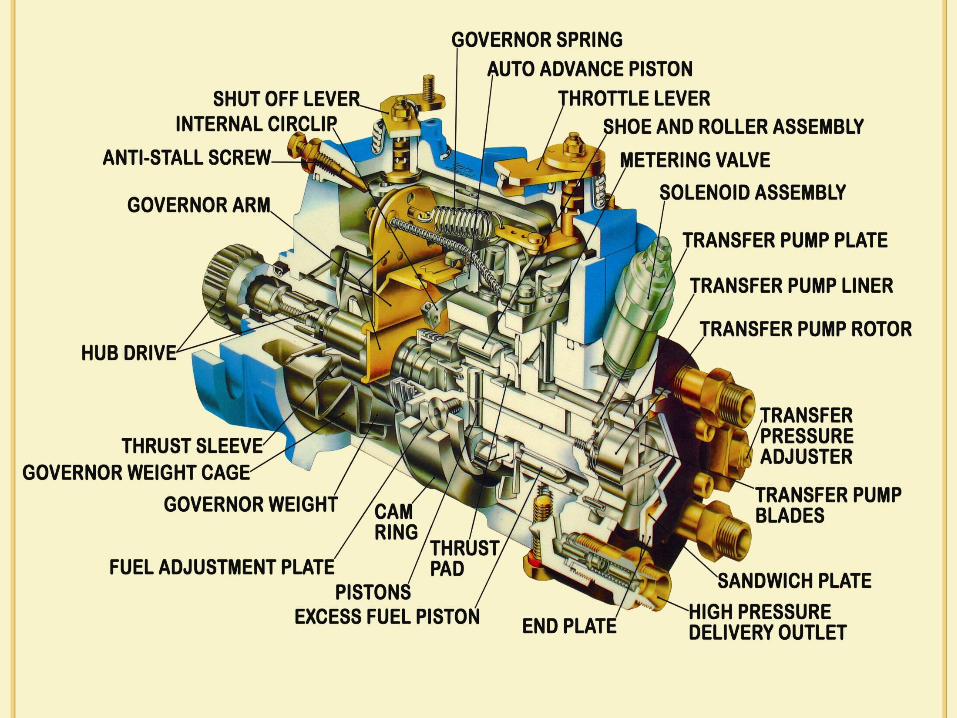
Distributor Fuel Pump System
Distributor
GearDrive
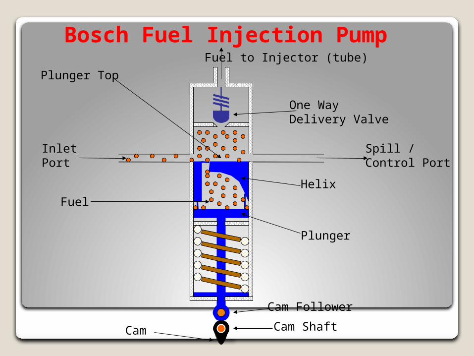
Bosch Fuel Injection Pump
Spill /Control Port
InletPort
Cam Follower
Cam ShaftCam
Plunger
Helix
One WayDelivery Valve
Fuel to Injector (tube)
Plunger Top
Fuel
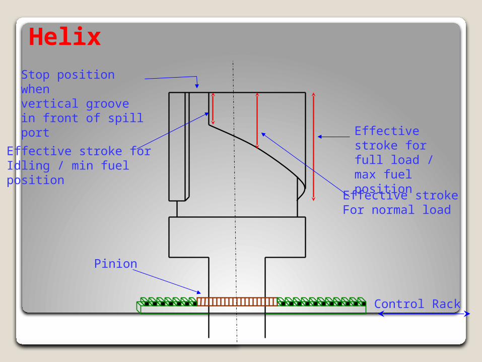
Helix
Pinion
Control Rack
Effective stroke For normal load
Effective stroke for full load / max fuel position
Effective stroke forIdling / min fuelposition
Stop position whenvertical groovein front of spill port
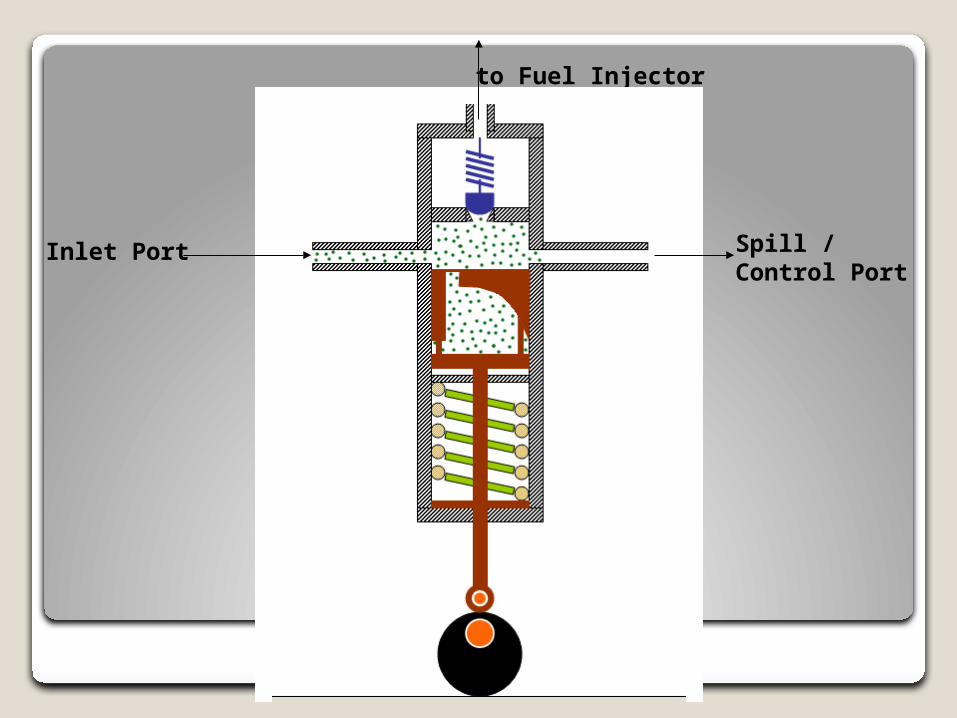
to Fuel Injector
Spill / Control Port
Inlet Port

Lecture No 18
Learning Objectives: • To understand working of distributor type of fuel pump • To learn about various types of injector nozzles
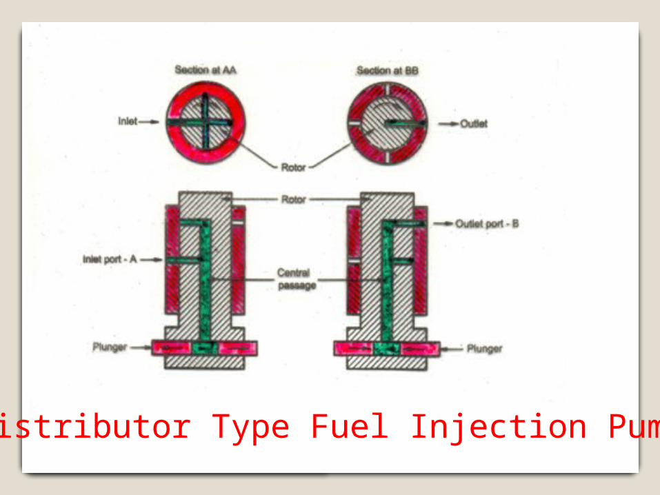
Distributor Type Fuel Injection Pump
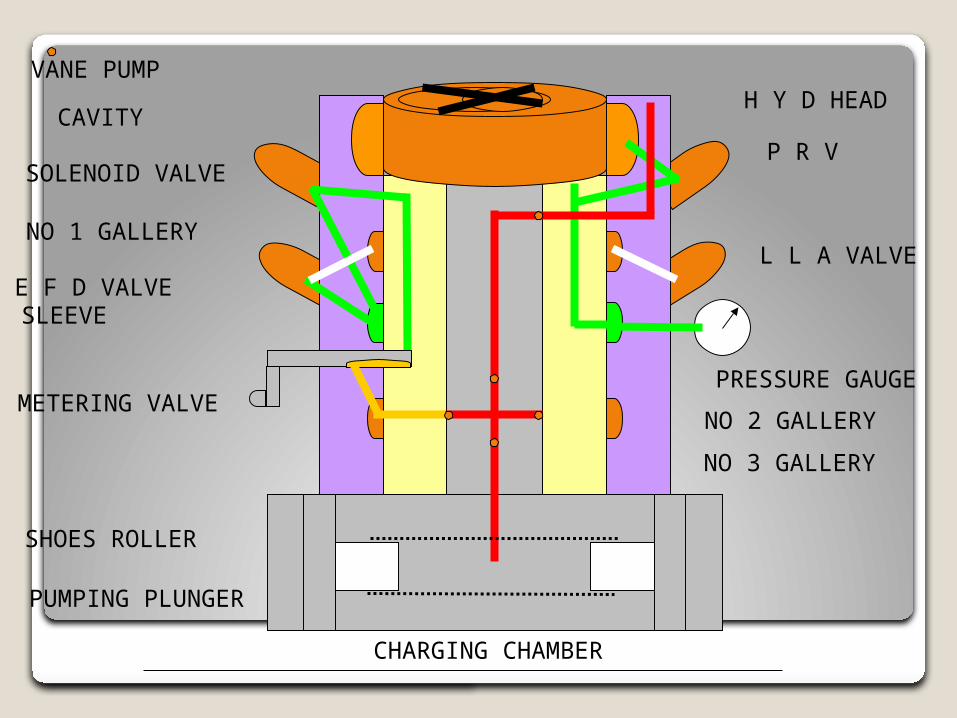
METERING VALVE
SHOES ROLLER
PUMPING PLUNGER
E F D VALVE
SOLENOID VALVEP R V
L L A VALVE
PRESSURE GAUGE
NO 1 GALLERY
NO 2 GALLERY
NO 3 GALLERY
CAVITY
VANE PUMP
CHARGING CHAMBER
H Y D HEAD
SLEEVE
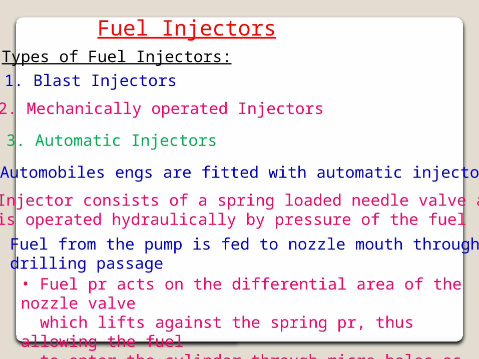
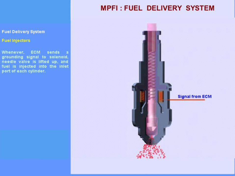
Fuel InjectorsTypes of Fuel Injectors:
1. Blast Injectors
2. Mechanically operated Injectors
3. Automatic Injectors
• Automobiles engs are fitted with automatic injectors
• Injector consists of a spring loaded needle valve and is operated hydraulically by pressure of the fuel
• Fuel from the pump is fed to nozzle mouth through drilling passage• Fuel pr acts on the differential area of the nozzle valve which lifts against the spring pr, thus allowing the fuel to enter the cylinder through micro-holes as spray
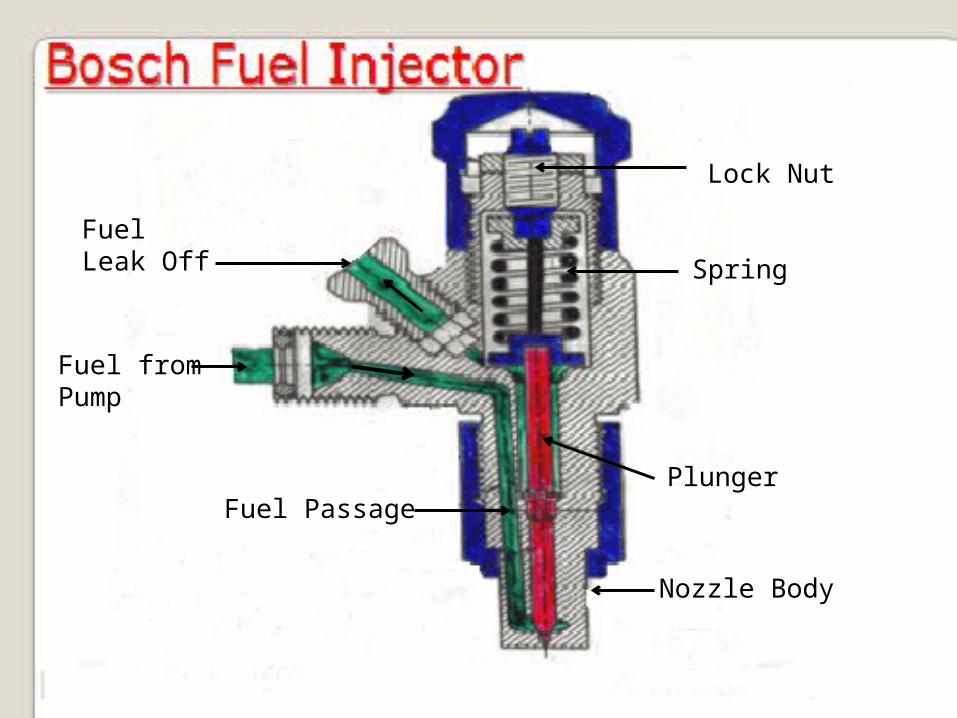
Nozzle Body
Plunger
Spring
Lock Nut
FuelLeak Off
Fuel fromPump
Fuel Passage
Types of NozzlesSingle Hole Nozzle:
• Generally used in Open/DI combustion chambers
• Size of hole around 0.2mm or more
• Hole may be drilled in the centre or at an angle to the centre line of nozzle to meet specific requirement of combustion chamber, in which air has direction
• Due to single hole, high injection pressure is needed
• Has tendency to dribble
• Spray angle is very narrow, about 15˚, this being unfavorable for mixing
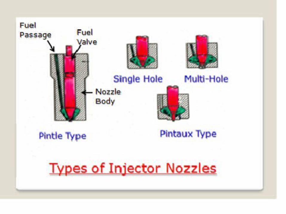
Types of NozzlesMulti-hole Nozzle:• Generally used in Open/DI combustion chambers
• Number of holes vary from 4 to 16 and size from 1.5mm to 0.35mm
• Generally, holes are drilled symmetrically but in some cases it may not be so due to comb chamber design
• High injection pressure (200 to 300 bar) needed
• Good mixing due to high fuel velocity
• Low heat losses due to slow movement of air and DI combustion chamber gives good cold starting performance
Types of NozzlesPintle Nozzle:• In order to avoid weak injection and dribbling, the spindle is provided with a cylindrical or conical projection called pintle, which protrudes through the mouth of nozzle body• When the valve starts lifting, the pintle partially blocks the orifice and thus does not allow the pressure drop to be greater• As the lift of the valve increases, the orifice is uncovered and full area for fuel flow is available, thus avoiding the dribbling• Hollow conical spray is achieved up to 60˚ angle• Gives good atomization at lower fuel pressure
• Used in pre-comb, air-cell or high swirl comb chambers
Types of NozzlesPintaux Nozzle:• This is the development over pintle nozzle and has an auxiliary hole drilled in nozzle body
• Auxiliary hole allows small amount of fuel to be injected in the upstream direction at a time slightly in advance of the main down stream injection
• At low speeds, the needle valve does not lift, resulting in very good cold starting performance
• Pintaux nozzle has the tendency for the auxiliary hole to choke, hence better fuel filtering unit is required
• Velocity of fuel for good atomization around 400 m/s
CombustionIn
CI Engines
Lecture No 19
Learning Objectives: • To understand combustion phenomenon in CI engines & combustion stages • To understand effect of various factors on combustion
70 60 50 40 30 20 10 0 10 20 30 40 50 60 70
C
D
E
AB
p
θ
F
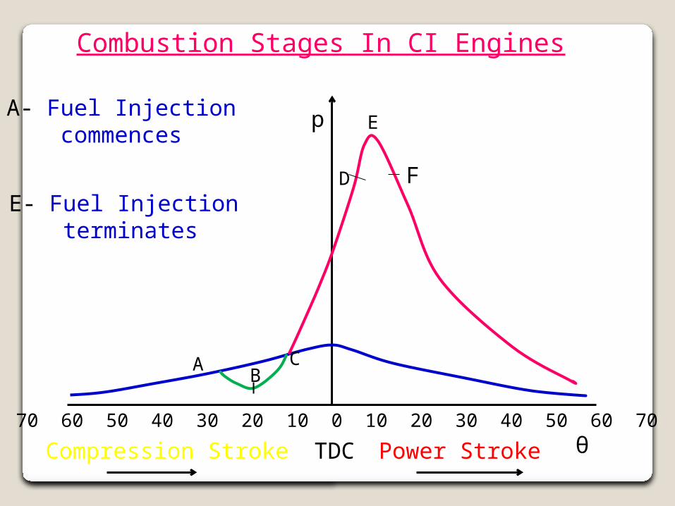
Combustion Stages In CI Engines
Compression Stroke TDC Power Stroke
A- Fuel Injection commences
E- Fuel Injection terminates

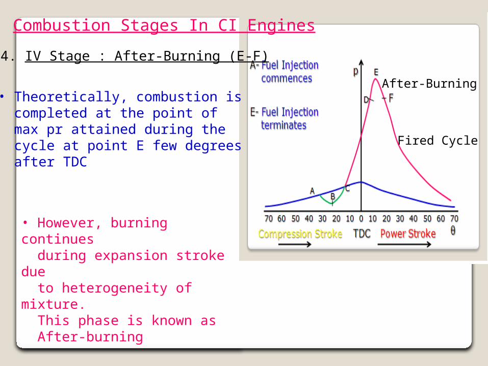
Combustion Stages In CI Engines• Air is compressed during compression stroke and raised to higher pr & temp by using CR from 16 to 20• Temp of air attained (450-550°C) is far above SIT (270-300°C) of diesel• Fuel is injected at very high pr (120-300 bar) at about 20-35° before TDC. Point A represents the time, at which fuel injection starts
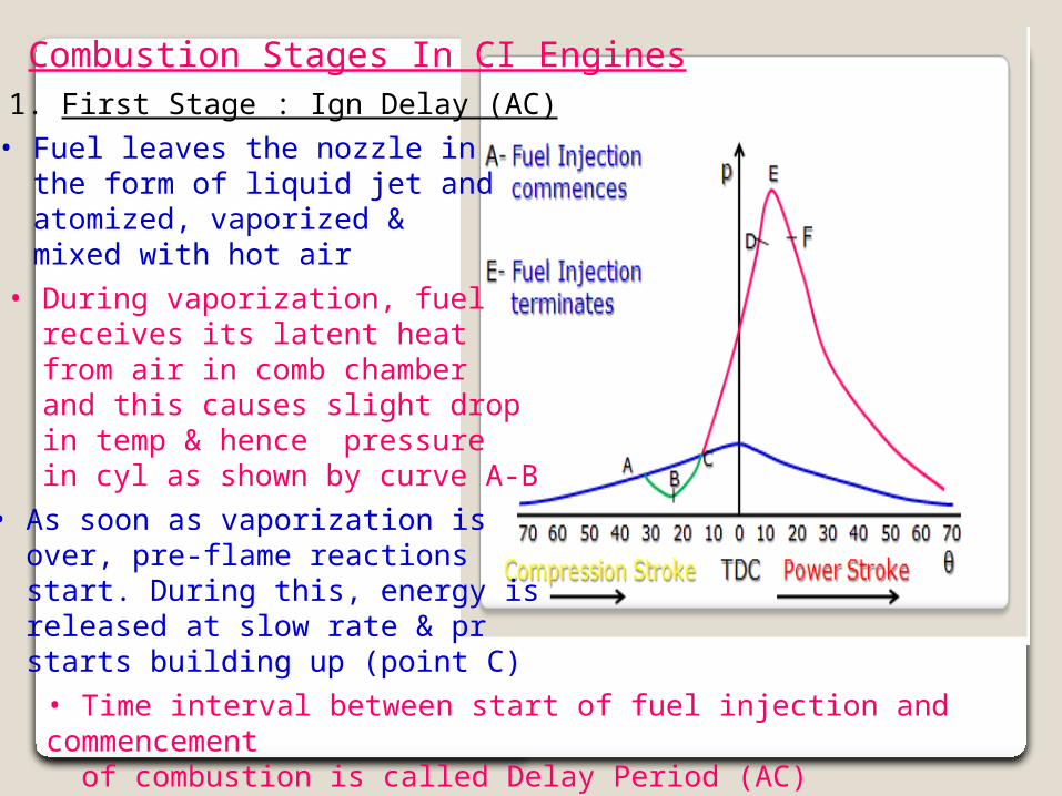
Combustion Stages In CI Engines1. First Stage : Ign Delay (AC)• Fuel leaves the nozzle in the form of liquid jet and atomized, vaporized & mixed with hot air• During vaporization, fuel receives its latent heat from air in comb chamber and this causes slight drop in temp & hence pressure in cyl as shown by curve A-B• As soon as vaporization is over, pre-flame reactions start. During this, energy is released at slow rate & pr starts building up (point C) • Time interval between start of fuel injection and commencement of combustion is called Delay Period (AC)
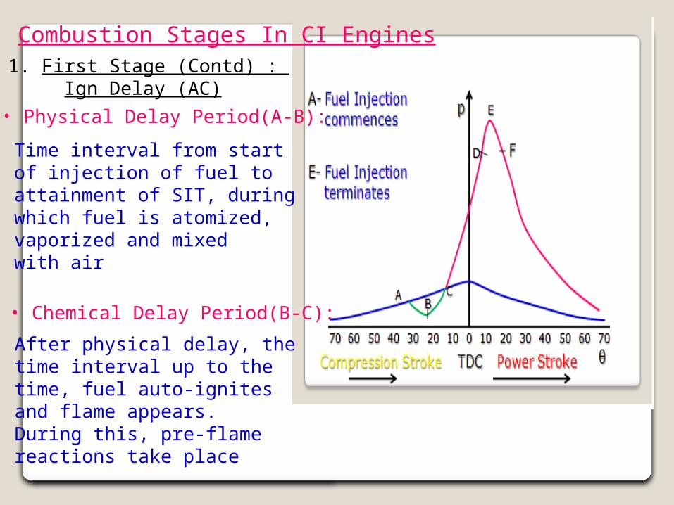
Combustion Stages In CI Engines1. First Stage (Contd) : Ign Delay (AC)• Physical Delay Period(A-B):
• Chemical Delay Period(B-C):
Time interval from start of injection of fuel to attainment of SIT, duringwhich fuel is atomized,vaporized and mixed with air
After physical delay, thetime interval up to thetime, fuel auto-ignites and flame appears. During this, pre-flamereactions take place
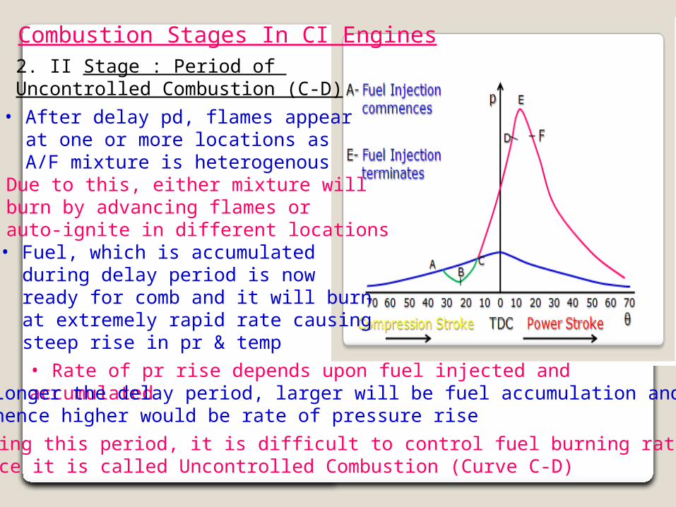
Combustion Stages In CI Engines2. II Stage : Period of Uncontrolled Combustion (C-D)• After delay pd, flames appear at one or more locations as A/F mixture is heterogenous• Due to this, either mixture will burn by advancing flames or auto-ignite in different locations • Fuel, which is accumulated during delay period is now ready for comb and it will burn at extremely rapid rate causing steep rise in pr & temp• Rate of pr rise depends upon fuel injected and accumulated• Longer the delay period, larger will be fuel accumulation and hence higher would be rate of pressure rise• During this period, it is difficult to control fuel burning rate and hence it is called Uncontrolled Combustion (Curve C-D)
Combustion Stages In CI Engines
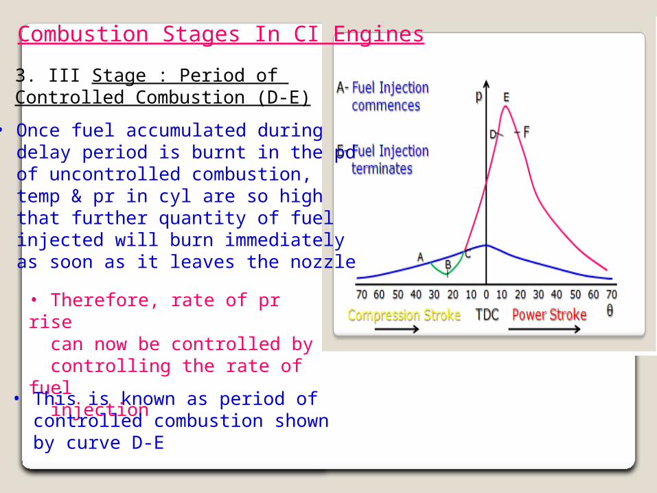
3. III Stage : Period of Controlled Combustion (D-E)
• Once fuel accumulated during delay period is burnt in the pd of uncontrolled combustion, temp & pr in cyl are so high that further quantity of fuel injected will burn immediately as soon as it leaves the nozzle
• Therefore, rate of pr rise can now be controlled by controlling the rate of fuel injection
• This is known as period of controlled combustion shown by curve D-E
Combustion Stages In CI Engines
4. IV Stage : After-Burning (E-F)
• Theoretically, combustion is completed at the point of max pr attained during the cycle at point E few degrees after TDC
• However, burning continues during expansion stroke due to heterogeneity of mixture. This phase is known as After-burning
Fired Cycle
After-Burning
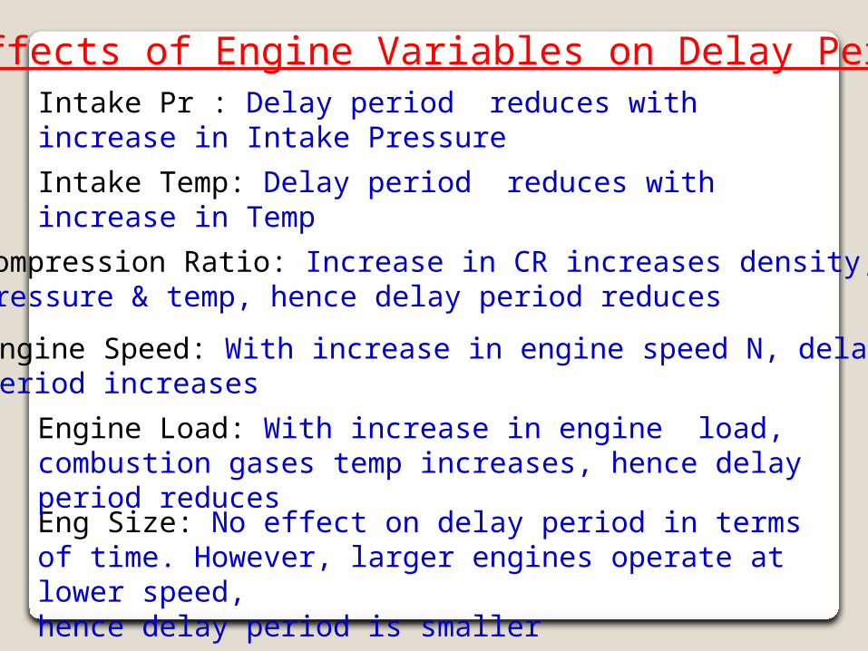
Effects of Engine Variables on Delay PeriodIntake Pr : Delay period reduces with increase in Intake Pressure
Compression Ratio: Increase in CR increases density, pressure & temp, hence delay period reduces
Eng Size: No effect on delay period in terms of time. However, larger engines operate at lower speed, hence delay period is smaller
Engine Speed: With increase in engine speed N, delay period increases
Engine Load: With increase in engine load, combustion gases temp increases, hence delay period reduces
Intake Temp: Delay period reduces with increase in Temp
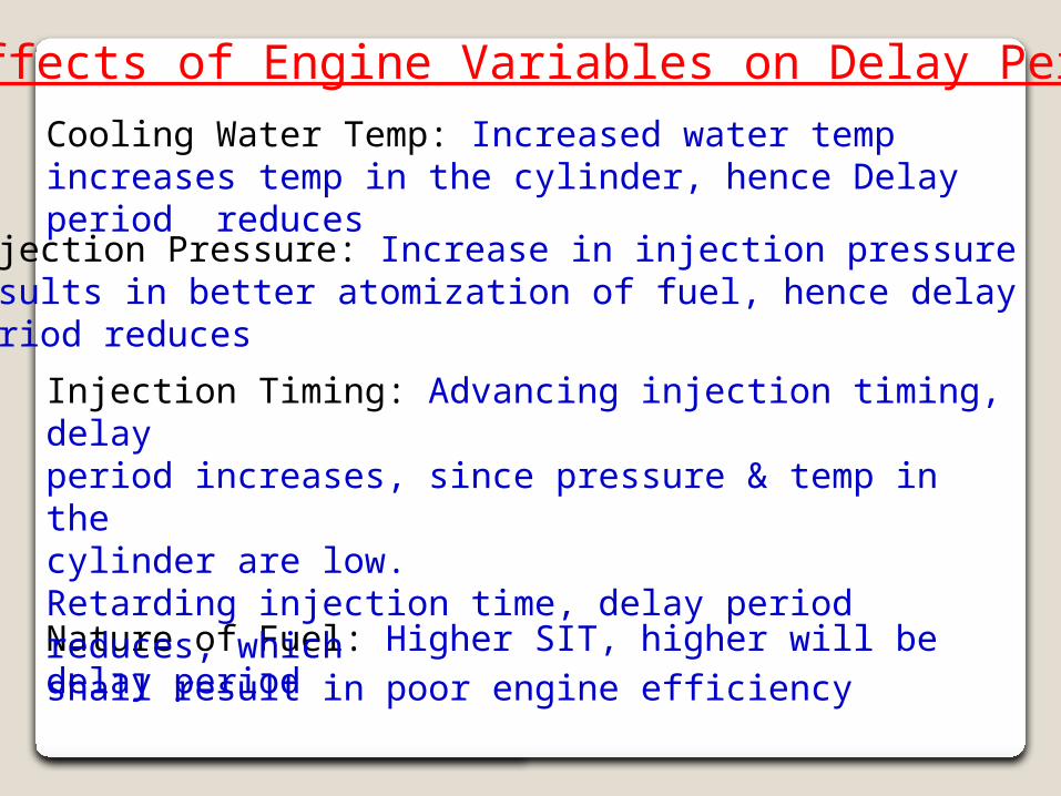
Effects of Engine Variables on Delay Period
Injection Pressure: Increase in injection pressure results in better atomization of fuel, hence delay period reduces
Nature of Fuel: Higher SIT, higher will be delay period
Injection Timing: Advancing injection timing, delay period increases, since pressure & temp in the cylinder are low.Retarding injection time, delay period reduces, which shall result in poor engine efficiency
Cooling Water Temp: Increased water temp increases temp in the cylinder, hence Delay period reduces
Lecture No 20
Learning Objectives: • To understand knocking phenomenon in CI engines • To understand effect of knocking and its control & comparison with SI engines
Knock In CI Engines
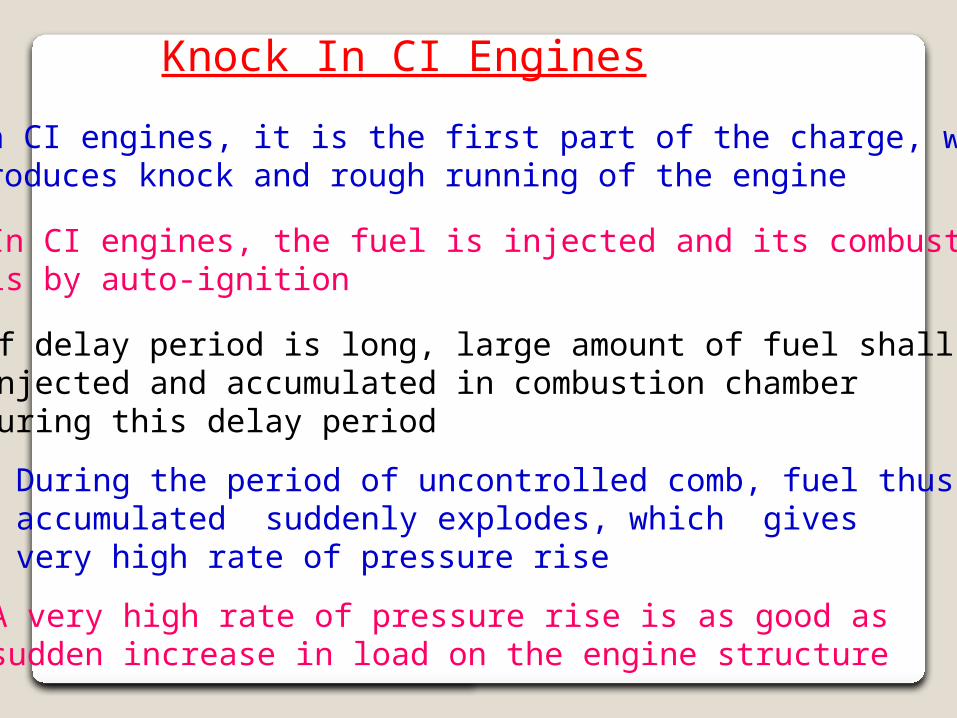
• In CI engines, it is the first part of the charge, which produces knock and rough running of the engine
• In CI engines, the fuel is injected and its combustion is by auto-ignition
• If delay period is long, large amount of fuel shall be injected and accumulated in combustion chamber during this delay period
• During the period of uncontrolled comb, fuel thus accumulated suddenly explodes, which gives very high rate of pressure rise
• A very high rate of pressure rise is as good as sudden increase in load on the engine structure
Knock In CI Engines (Contd)
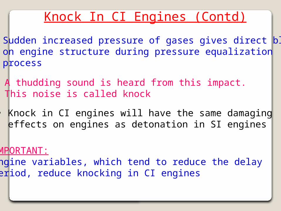
• Sudden increased pressure of gases gives direct blow on engine structure during pressure equalization process
• A thudding sound is heard from this impact. This noise is called knock
• Knock in CI engines will have the same damaging effects on engines as detonation in SI engines
IMPORTANT:Engine variables, which tend to reduce the delay period, reduce knocking in CI engines
Comparison of Knocking in SI & CI Engines
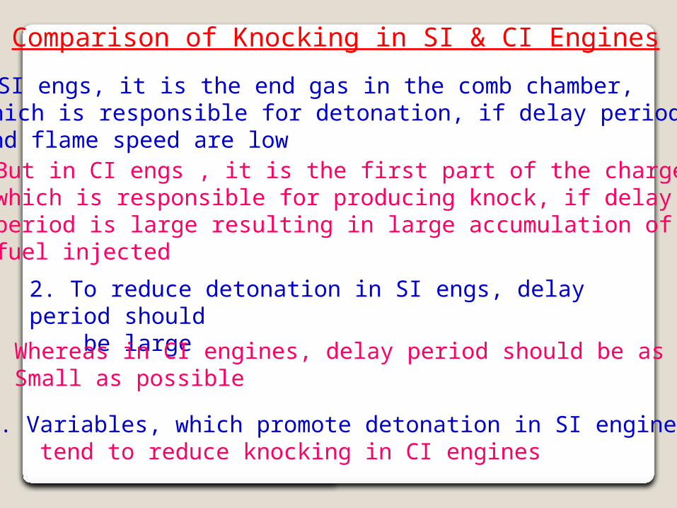
1. In SI engs, it is the end gas in the comb chamber, which is responsible for detonation, if delay period and flame speed are low
But in CI engs , it is the first part of the charge,which is responsible for producing knock, if delayperiod is large resulting in large accumulation of fuel injected
2. To reduce detonation in SI engs, delay period should be large
Whereas in CI engines, delay period should be as Small as possible
3. Variables, which promote detonation in SI engines, tend to reduce knocking in CI engines
Comparison of Knocking in SI & CI Engines
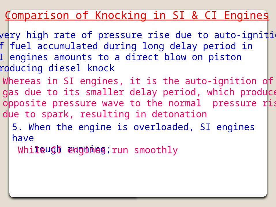
4. A very high rate of pressure rise due to auto-ignition of fuel accumulated during long delay period in CI engines amounts to a direct blow on piston producing diesel knock
Whereas in SI engines, it is the auto-ignition of endgas due to its smaller delay period, which producesopposite pressure wave to the normal pressure risedue to spark, resulting in detonation
5. When the engine is overloaded, SI engines have rough running;
While CI engines run smoothly
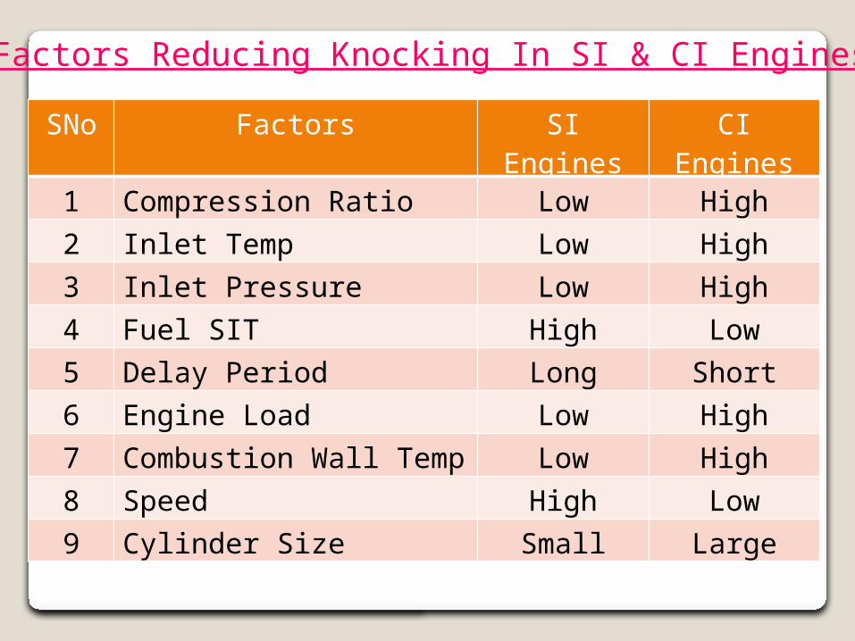
Factors Reducing Knocking In SI & CI Engines
SNo Factors SI Engines CI Engines
1 Compression Ratio Low High
2 Inlet Temp Low High
3 Inlet Pressure Low High
4 Fuel SIT High Low
5 Delay Period Long Short
6 Engine Load Low High
7 Combustion Wall Temp Low High
8 Speed High Low
9 Cylinder Size Small Large
Lecture No 21
Learning Objectives: • To understand various types of combustion chambers
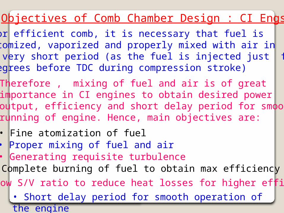
Objectives of Comb Chamber Design : CI Engs For efficient comb, it is necessary that fuel is atomized, vaporized and properly mixed with air in a very short period (as the fuel is injected just few degrees before TDC during compression stroke)
Therefore , mixing of fuel and air is of great importance in CI engines to obtain desired power output, efficiency and short delay period for smooth running of engine. Hence, main objectives are:
• Fine atomization of fuel• Proper mixing of fuel and air• Generating requisite turbulence• Complete burning of fuel to obtain max efficiency• Low S/V ratio to reduce heat losses for higher efficiency• Short delay period for smooth operation of the engine
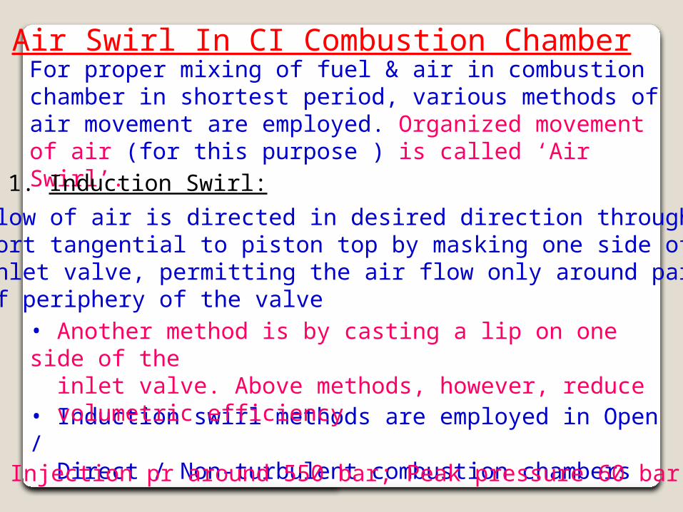
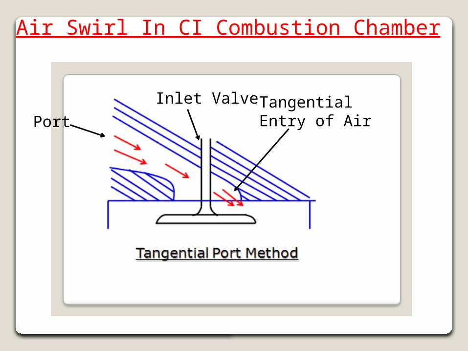
Air Swirl In CI Combustion ChamberFor proper mixing of fuel & air in combustion chamber in shortest period, various methods of air movement are employed. Organized movement of air (for this purpose ) is called ‘Air Swirl’.1. Induction Swirl:
• Induction swirl methods are employed in Open / Direct / Non-turbulent combustion chambers
• Flow of air is directed in desired direction through a port tangential to piston top by masking one side of inlet valve, permitting the air flow only around part of periphery of the valve• Another method is by casting a lip on one side of the inlet valve. Above methods, however, reduce volumetric efficiency
• Injection pr around 550 bar; Peak pressure 60 bar
Air Swirl In CI Combustion Chamber
PortTangentialEntry of Air
Inlet Valve
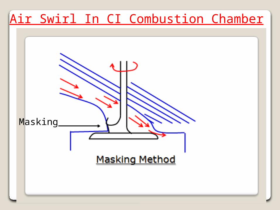
Masking
Air Swirl In CI Combustion Chamber
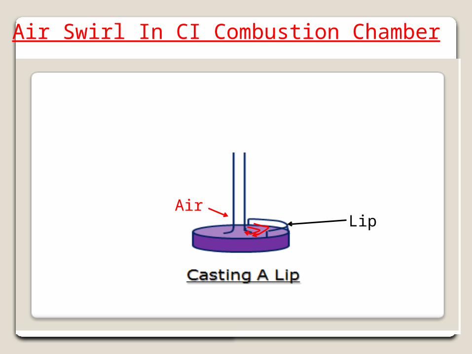
Lip
Air Swirl In CI Combustion Chamber
Air
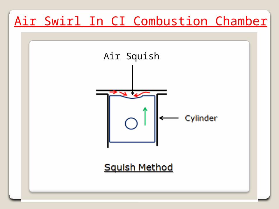
Air Squish
Air Swirl In CI Combustion Chamber
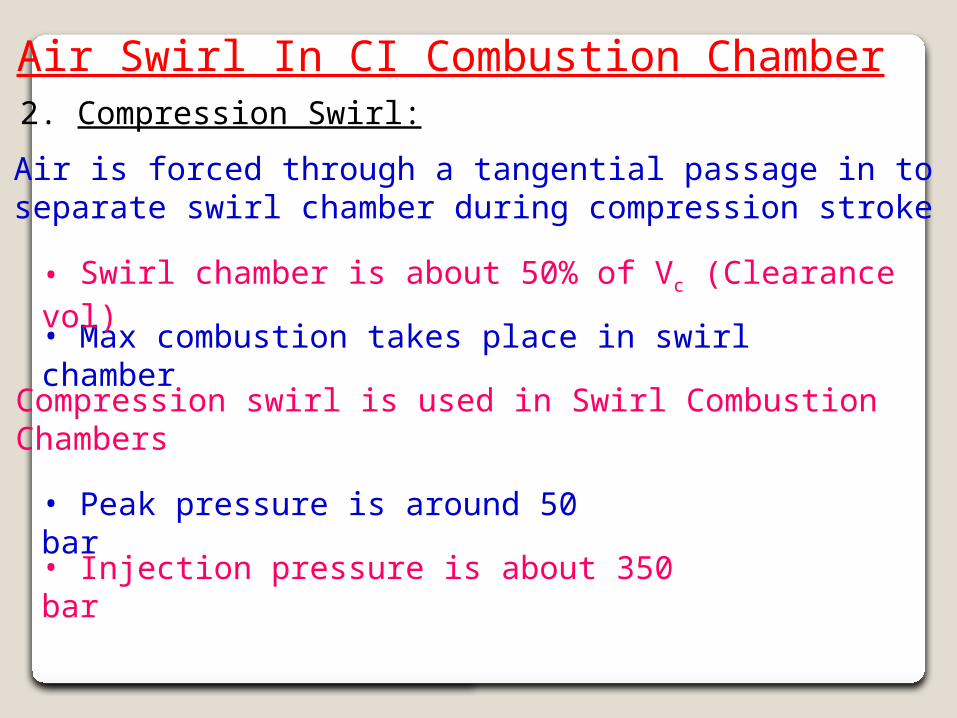
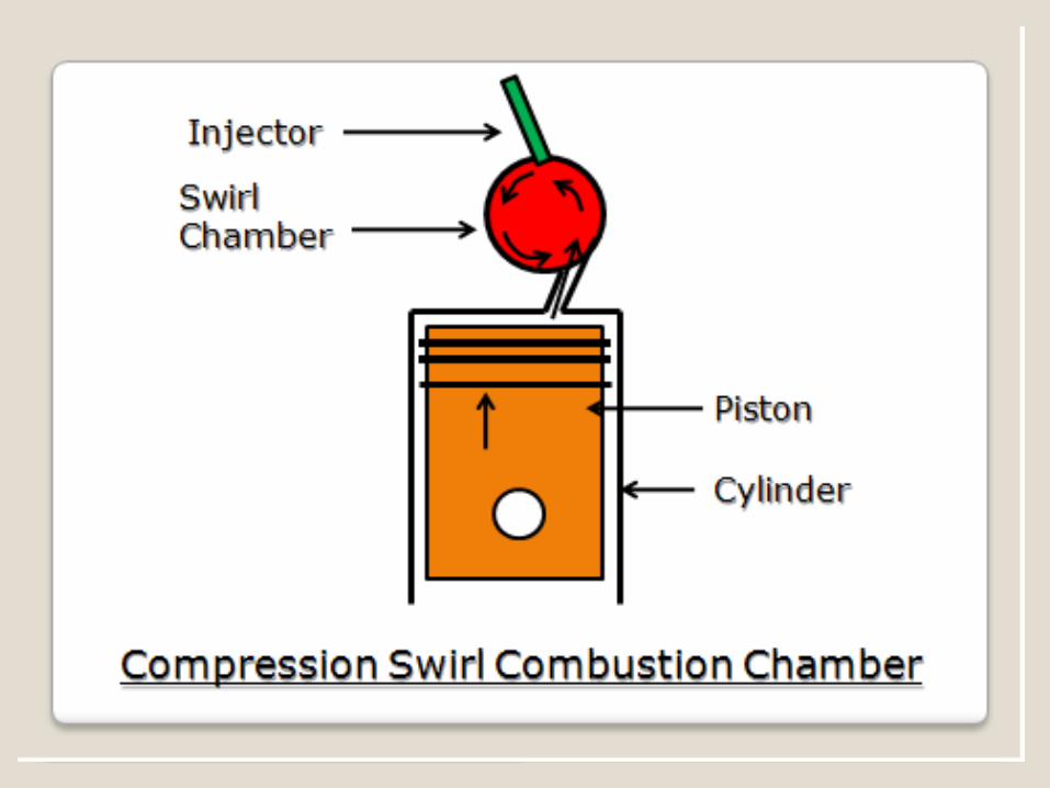
Air Swirl In CI Combustion Chamber2. Compression Swirl:
• Max combustion takes place in swirl chamber
• Air is forced through a tangential passage in to separate swirl chamber during compression stroke
• Swirl chamber is about 50% of Vc (Clearance vol)
• Compression swirl is used in Swirl Combustion Chambers
• Peak pressure is around 50 bar
• Injection pressure is about 350 bar

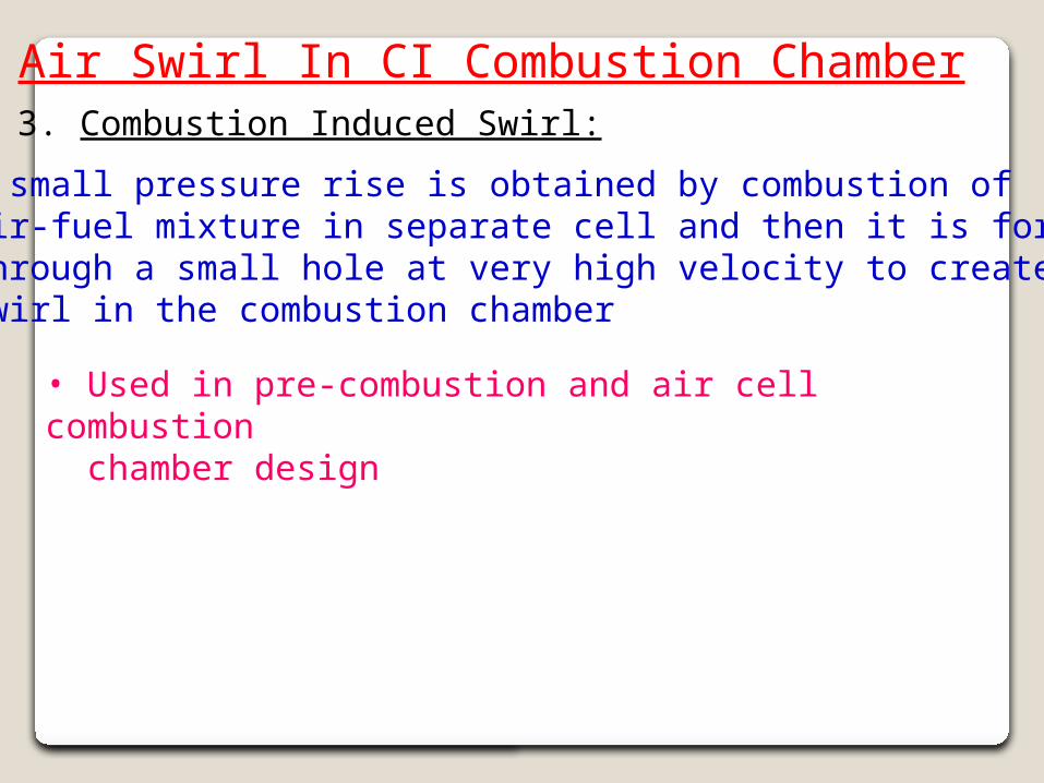
Air Swirl In CI Combustion Chamber3. Combustion Induced Swirl:
• A small pressure rise is obtained by combustion of air-fuel mixture in separate cell and then it is forced through a small hole at very high velocity to create swirl in the combustion chamber
• Used in pre-combustion and air cell combustion chamber design
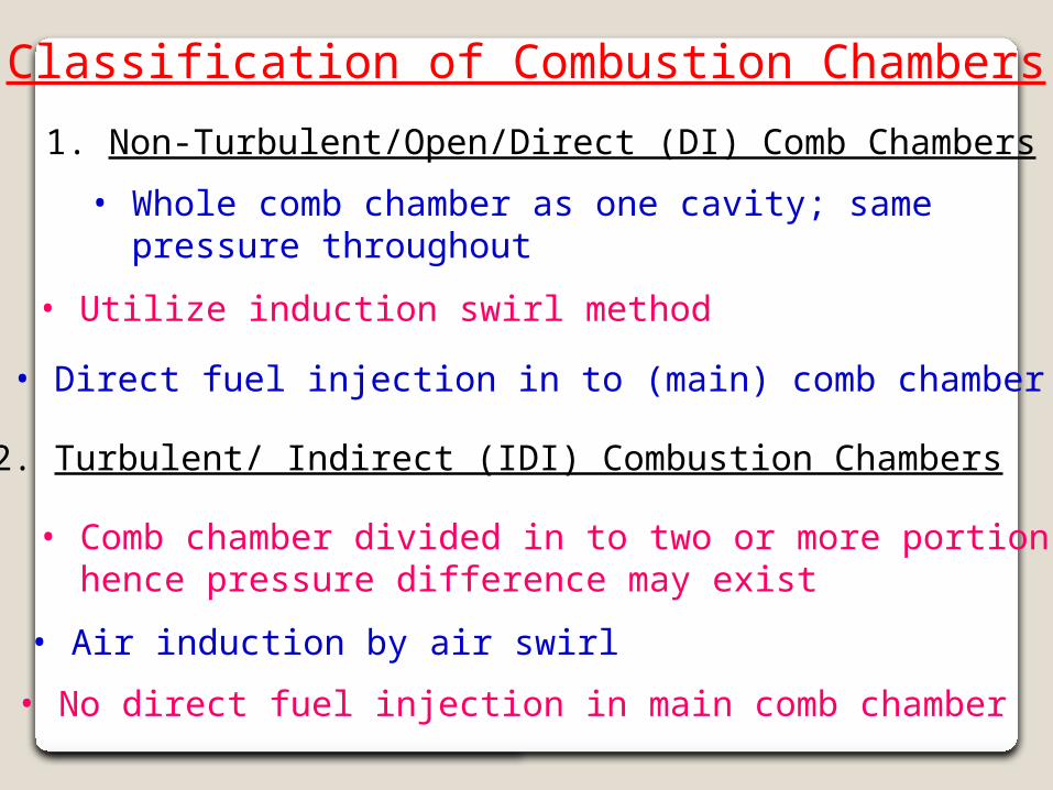
Classification of Combustion Chambers
1. Non-Turbulent/Open/Direct (DI) Comb Chambers
2. Turbulent/ Indirect (IDI) Combustion Chambers
• Air induction by air swirl
• Direct fuel injection in to (main) comb chamber
• No direct fuel injection in main comb chamber
• Comb chamber divided in to two or more portions hence pressure difference may exist
• Whole comb chamber as one cavity; same pressure throughout
• Utilize induction swirl method
Classification of Combustion Chambers
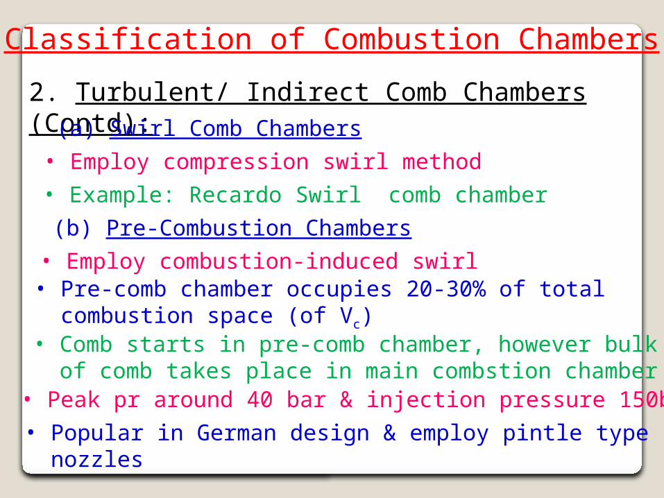
2. Turbulent/ Indirect Comb Chambers (Contd):
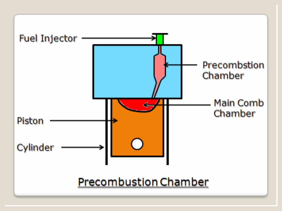
(b) Pre-Combustion Chambers
• Pre-comb chamber occupies 20-30% of total combustion space (of Vc)
• Example: Recardo Swirl comb chamber
• Comb starts in pre-comb chamber, however bulk of comb takes place in main combstion chamber
• Employ combustion-induced swirl
(a) Swirl Comb Chambers• Employ compression swirl method
• Peak pr around 40 bar & injection pressure 150bar• Popular in German design & employ pintle type nozzles
Classification of Combustion Chambers
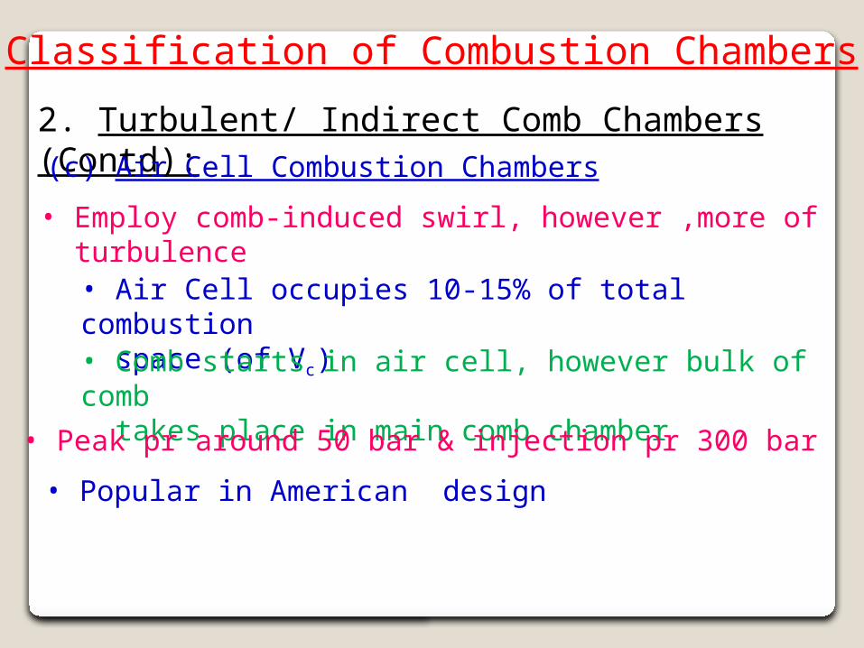
2. Turbulent/ Indirect Comb Chambers (Contd):
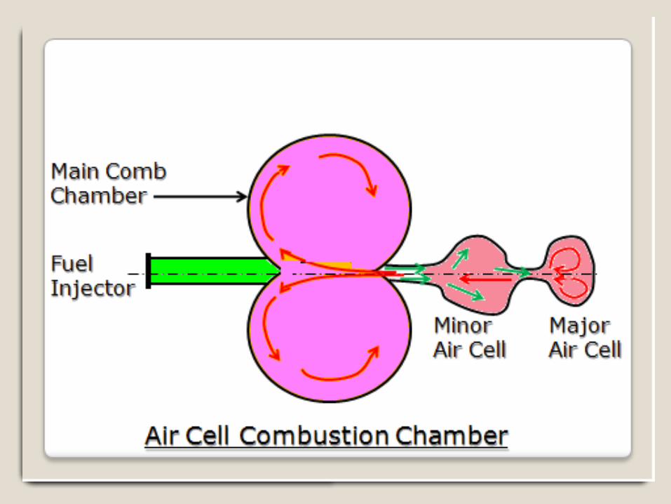
(c) Air Cell Combustion Chambers
• Air Cell occupies 10-15% of total combustion space (of Vc) • Comb starts in air cell, however bulk of comb takes place in main comb chamber
• Employ comb-induced swirl, however ,more of turbulence
• Peak pr around 50 bar & injection pr 300 bar
• Popular in American design
Classification of Combustion Chambers
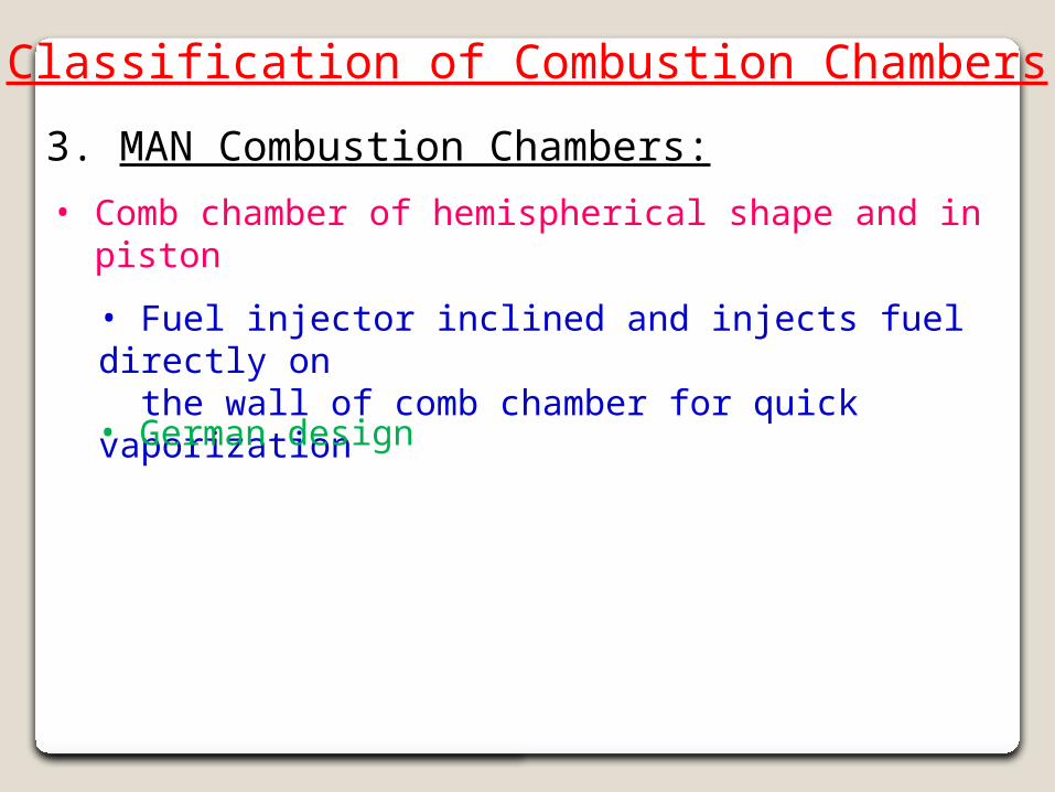
3. MAN Combustion Chambers:
• Fuel injector inclined and injects fuel directly on the wall of comb chamber for quick vaporization
• Comb chamber of hemispherical shape and in piston
• German design
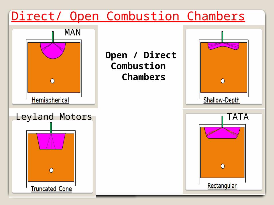
Direct/ Open Combustion Chambers
Open / Direct Combustion Chambers
MAN
Leyland Motors TATA

Lecture No 22
Learning Objectives: • To learn about fuel rating and additives for CI engines
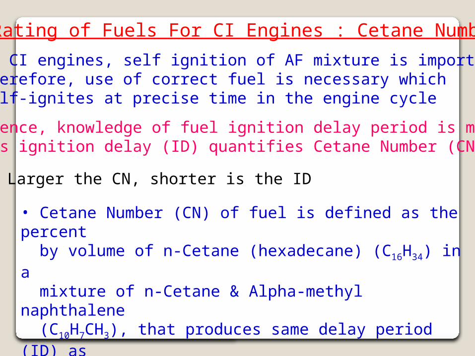
Rating of Fuels For CI Engines : Cetane Number
• In CI engines, self ignition of AF mixture is important. Therefore, use of correct fuel is necessary which self-ignites at precise time in the engine cycle
• Hence, knowledge of fuel ignition delay period is must as ignition delay (ID) quantifies Cetane Number (CN)
• Larger the CN, shorter is the ID
• Cetane Number (CN) of fuel is defined as the percent by volume of n-Cetane (hexadecane) (C16H34) in a mixture of n-Cetane & Alpha-methyl naphthalene (C10H7CH3), that produces same delay period (ID) as the standard fuel under same test conditions
Rating of Fuels For CI Engines : Cetane Number
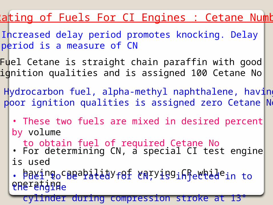
• Increased delay period promotes knocking. Delay period is a measure of CN
• Fuel Cetane is straight chain paraffin with good ignition qualities and is assigned 100 Cetane No
• Hydrocarbon fuel, alpha-methyl naphthalene, having poor ignition qualities is assigned zero Cetane No
• These two fuels are mixed in desired percent by volume to obtain fuel of required Cetane No• For determining CN, a special CI test engine is used having capability of varying CR while operating
• Fuel to be rated for CN, is injected in to the engine cylinder during compression stroke at 13° BTDC
Rating of Fuels For CI Engines : Cetane Number
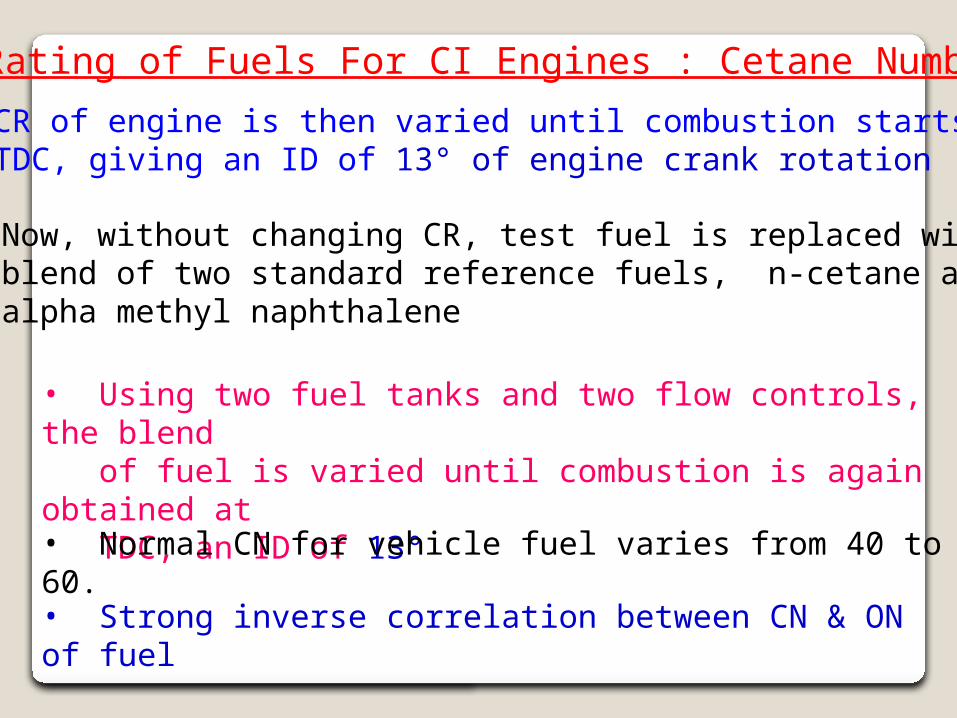
• CR of engine is then varied until combustion starts at TDC, giving an ID of 13° of engine crank rotation
• Now, without changing CR, test fuel is replaced with blend of two standard reference fuels, n-cetane and alpha methyl naphthalene
• Using two fuel tanks and two flow controls, the blend of fuel is varied until combustion is again obtained at TDC, an ID of 13°
• Normal CN for vehicle fuel varies from 40 to 60.
• Strong inverse correlation between CN & ON of fuel
Additives for CI Engine Fuels
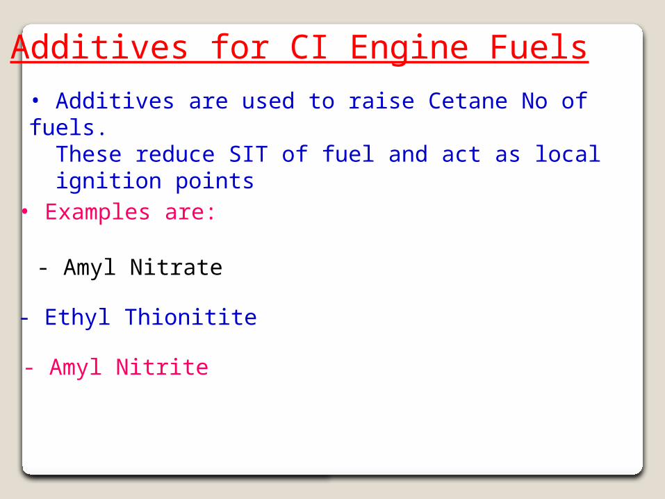
• Additives are used to raise Cetane No of fuels. These reduce SIT of fuel and delay period and act as local ignition points
• Examples are:
- Amyl Nitrate
- Ethyl Thionitite
- Amyl Nitrite
Rating of Fuels For CI Engines : Cetane Number
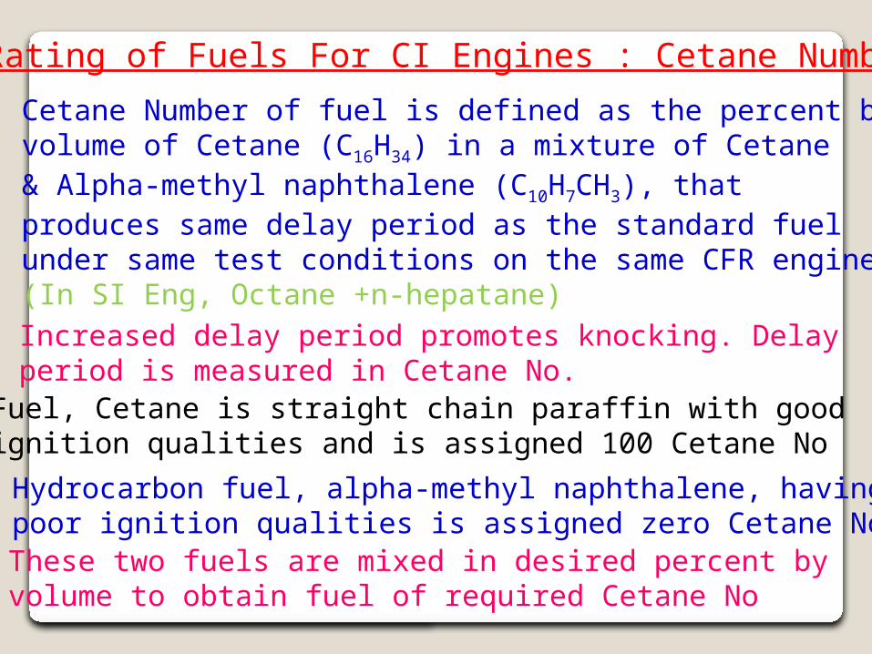
• Cetane Number of fuel is defined as the percent by volume of Cetane (C16H34) in a mixture of Cetane & Alpha-methyl naphthalene (C10H7CH3), that produces same delay period as the standard fuel under same test conditions on the same CFR engine. (In SI Eng, Octane +n-hepatane)• Increased delay period promotes knocking. Delay period is measured in Cetane No.• Fuel, Cetane is straight chain paraffin with good ignition qualities and is assigned 100 Cetane No
• Hydrocarbon fuel, alpha-methyl naphthalene, having poor ignition qualities is assigned zero Cetane No • These two fuels are mixed in desired percent by volume to obtain fuel of required Cetane No
Additives for CI Engine Fuels
• Additives are used to raise Cetane No of fuels. These reduce SIT of fuel and act as local ignition points
• Examples are:
- Amyl Nitrate
- Ethyl Thionitite
- Amyl Nitrite
End of Unit III
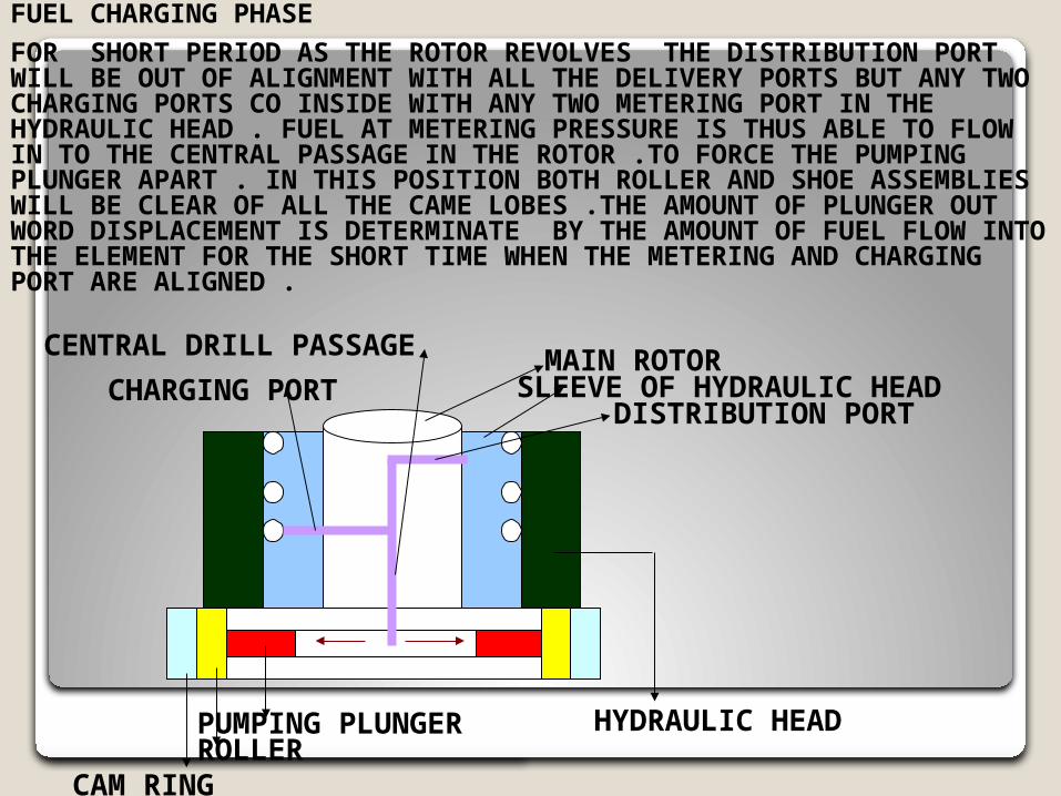
FUEL CHARGING PHASE
FOR SHORT PERIOD AS THE ROTOR REVOLVES THE DISTRIBUTION PORT WILL BE OUT OF ALIGNMENT WITH ALL THE DELIVERY PORTS BUT ANY TWO CHARGING PORTS CO INSIDE WITH ANY TWO METERING PORT IN THE HYDRAULIC HEAD . FUEL AT METERING PRESSURE IS THUS ABLE TO FLOW IN TO THE CENTRAL PASSAGE IN THE ROTOR .TO FORCE THE PUMPING PLUNGER APART . IN THIS POSITION BOTH ROLLER AND SHOE ASSEMBLIES WILL BE CLEAR OF ALL THE CAME LOBES .THE AMOUNT OF PLUNGER OUT WORD DISPLACEMENT IS DETERMINATE BY THE AMOUNT OF FUEL FLOW INTO THE ELEMENT FOR THE SHORT TIME WHEN THE METERING AND CHARGING PORT ARE ALIGNED .
SLEEVE OF HYDRAULIC HEADMAIN ROTOR
DISTRIBUTION PORTCHARGING PORT
CENTRAL DRILL PASSAGE
PUMPING PLUNGERROLLER
CAM RING
HYDRAULIC HEAD
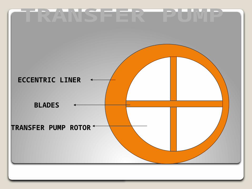
ECCENTRIC LINER
BLADES
TRANSFER PUMP ROTOR