combustion heat release rate analysis of …jestec.taylors.edu.my/vol 10 issue 8 august 2015/volume...
TRANSCRIPT
Journal of Engineering Science and Technology Vol. 10, No. 8 (2015) 1086 - 1102 © School of Engineering, Taylor’s University
1086
COMBUSTION HEAT RELEASE RATE ANALYSIS OF C.I. ENGINE WITH SECONDARY CO-INJECTION OF DEE-H2O
SOLUTION - A VIBRATIONAL APPROACH
Y. V. V. SATYANARAYANA MURTHY, R. RAJESWARA REDDY
Mechanical Engineering Department, Gitam University, Visakhapatnam, India
*Corresponding Author: [email protected]
Abstract
This paper discusses the combustion propensity of single cylinder direct
injection engine fueled with palm kernel methyl ester (PKME), which is non-
edible oil and a secondary co-injection of saturated Diethyl ether (DEE) with
water. DEE along with water is fumigated through a high pressure nozzle fitted
to the inlet manifold of the engine and the flow rate of the secondary injection
was electronically controlled. DEE is known to improve the cold starting problem in engines when used in straight diesel fuel. However, its application
in emulsion form is little known. Experimental results show that for 5% DEE-
H2O solution injection, occurrence of maximum net heat release rate is delayed
due to controlled premixed combustion, which normally helped in better torque
conversion when the piston is in accelerated mode. Vibration measurements in
the frequency range of 900Hz to 1300Hz revealed that a new mode of
combustion has taken place with different excitation frequencies.
Keywords: Diesel engine, Diethyl ether, Ethanol, Heat release rate, Noise, Palm
Kernel methyl ester.
1. Introduction
Water in fuel is a widely adopted technique to reduce engine emissions. However,
direct injection of fixed percentage of water into the engine irrespective of the
engine load will lead to increased HC and CO emissions and increased brake
specific fuel consumption [1]. Direct injection of oil emulsions into the engine is
often adopted to control the diesel engine emissions. Water-Diesel emulsion could
reduce the NOx and smoke levels without much change in brake thermal
efficiency. The major drawback of water-fuel emulsion is its tendency to form air
bubbles leading to changes in fuel injection timings and poor engine performance
[2]. Hence, addition of DEE together with diesel-water emulsion could reduce both
Combustion Heat Rate Analysis of C.I. Engine with Secondary . . . . 1087
Journal of Engineering Science and Technology August 2015, Vol. 10(8)
Nomenclatures
CHRR Cumulative heat release rate
DEE Diethyl Ether
dmi Mass transfer at inlet
dQ Amount of Heat transfer
dQch Heat released due to chemical energy
dQht Convection heat transfer
dU Change in internal energy
dW Amount of Work done
FFT Fast Fourier Transform
hi Enthalphy change at inlet
NHRR Net heat release rate
PKME Palm Kernel Methyl Ester
SFC Specific fuel consumption
T’ Temperature of the gas flow out of the crevice volume
Tw Wall temperature
Vcr Crevice Volume
both NOx and HC emissions [3]. It has been shown that blends of DEE led
combustion and proceeded further toward completion than ethanol [4], the other
commonly added additive. The addition of DEE to biodiesel blends showed an
improvement in the efficiency of the engine and reduced NOX, HC and BSFC [5,
6, 7, 8]. It was reported that blends of DEE in POME (palm oil methyl ester)
resulted in an improvement in acid value, viscosity, density and pour point with
increasing content of DEE, accompanied by a slight decrease in energy content of
biodiesel [9].
However, the use of biodiesel as fuel increases vibrations in the engine [10]
when compared to conventional diesel fuel and certain biodiesel blends produce
more vibration over others. The reason for this increase in vibrations might be the
engine miss-firing and knocking at higher bio-diesel portions [11]. A variety of
signal processing methods like statistical methods, wavelet analysis, FFT analysis
etc., are being used to analyze the engine noise caused by vibration [12, 13]. The
noise sources of the engine are being identified by independent component analysis
which decomposes the measured signal into a number of independent components.
This technique helps to identify and study the noise source of individual
components and wavelet transform is then applied to represent the individual
component in the time frequency domain. Combining continuous wavelet transform
and individual component analysis, low level frequencies which are generally
dominated by the engine firing frequency can be identified [14]. Some researchers
developed techniques to study and analyze vibrations in engines [15, 16, 17]. Some
researchers studied the effect of biodiesel blends on engine vibrations. Heidary et al.
[18] has shown that biodiesel blends have a significant effect of engine vibrations
and that the magnitude of vibration acceleration in vertical axis was more than that
in the other two axes and magnitude of vibration acceleration in the longitudinal
axis was more than that in the lateral axis. The fact that different biodiesel blends
result in different values of vibration was corroborated in a later study [10].
In one of the author’s earlier work [19], knock detection and engine
performance on single cylinder DI- diesel engine was evaluated using pure

1088 Y. V. V. S. Murthy and R. R. Reddy
Journal of Engineering Science and Technology August 2015, Vol. 10(8)
vibration signature analysis. However, pure water was used instead of a blend and
performance characteristics such as engine pressure, combustion heat release rate
and net heat release rate were not studied. In that study, it was proven that the
injection of water has resulted in longer time duration of combustion during firing
stroke. In a more recent study by the author [20], engine performance using pure
diesel and biodiesel as fuel with secondary injection of H2O-DEE was studied.
Engine performance characteristics such as brake specific fuel consumption,
brake thermal efficiency and emission characteristics such as release of un burnt
hydrocarbons, NOx, CO, CO2, O2, exhaust gas temperatures, smoke etc were
studied. It was concluded that mass flow rate of 5% vol. H2O – DEE solution is
beneficial in view of emission performance, especially on NO emissions.
However, vibration analysis was not performed in that study. Hence, a
combination of engine performance using both engine studies and vibration
studies seemed relevant in establishing the optimum performance characteristics.
In the current work, vibration studies along with engine performance studies
were conducted on single cylinder DI engine fuelled with palm kernel methyl
ester (PKME) with dual injection of DEE-H2O solution. The measured vibration
signal recorded was converted into FFT form. The time waveforms were
presented in graphic form and the combustion mode due to the secondary co-
injection of DEE-H2O was studied.
2. Heat Release Rate Calculation
In-cylinder pressure and crank angle signals were obtained from the engine data
logger for the load defined and stored on a high speed computer based digital data
acquisition system. The data was recorded for 100 cycles. After obtaining the data
for 100 cycles, the net heat release rate was calculated based on the first law of
thermodynamics by taking the average value of pressure crank angle data. The
present approach was to regard the cylinder contents as a single zone, whose
thermodynamic state and properties were modeled as being uniform throughout
the cylinder and represented by average values. No spatial variations were
considered, so the model was said to be zero-dimensional. Equation (1) was used
to model the single zone based on the 1st law of thermodynamics.
∑+−=i idmihdWdQdU (1)
2.1. Chemical Energy Released Calculation
The chemical energy released during combustion is calculated using Equation (2),
where dQch is the heat released due to chemical energy, dQht is the convection heat
transfer, Vcr, the crevice volume, Tw is the wall temperature and T’ is the
temperature of the gas flow out of the crevice volume. This ordinary differential
equation can easily be solved numerically for the net heat-release trace, if a cylinder
pressure trace is provided, together with an initial value for the heat release.
dpwT
crVTT
htdQpdVVdp
dpwRT
crVTRT
vc
htdQpdVVdp
chdQ
−+′+
−++
−+
−=
−+′+++
−+
−=
1
11
1
1
11
1
1
11
11
1
γγγγ
γ
γγγ
γ (2)

Combustion Heat Rate Analysis of C.I. Engine with Secondary . . . . 1089
Journal of Engineering Science and Technology August 2015, Vol. 10(8)
3. Experimental Setup
A four stroke, direct injection, naturally aspirated single cylinder diesel engine
was employed for the present study whose details are given in Table1.The
maximum solubility of DEE in water is 50ml/lit and the percentage of DEE blended
in water is around 5% vol/wt basis. This Water–DEE (DEE-H2O) solution was
injected at the suction end at a pressure of 3 kgf/cm2. The injection was controlled
electronically by a controlled injection pump designed with suitable hardware, and it
was timed to inject after the suction valve is fully opened. This DEE-H2O solution is
injected at 5%, 10%, 20%, 30% and 40% of the volume of the diesel injected. The
load on the engine can be changed with the dynamometer control panel. Full load on
the engine is equal to 40 kg on the spring balance. This dynamometer is popular for its
stable and consistent readings even in the case of minor variation in engine speed and
engine vibration. The tests were conducted at the rated speed of 1500 RPM at
different loads of 0 kg, 10 kg, 20 kg, 30 kg, and 40 kg measured in the spring balance.
Table 1. Test Model Specifications and Test Conditions.
Feature Specification
Type 4S, Single cylinder, compression ignition engine
Make Kirloskar AV-1
Rated power 3.7kW
Bore/Stroke 80 mm/110 mm
Compression ratio 16.5:1
No. of Cylinders 1
Cylinder Capacity 624cc
Dynamometer Electrical AC Dynamometer
Pressure (piezo sensor) 2000psi
Injection pressure 210bar
The engine was run with neat diesel and then with neat PKME while the
secondary injection of DEE-H2O solution was injected at the suction end with
different mass flow as indicated above. Engine tests were run on the same engine
and on same day for both diesel and PKME for each load, in order to have almost
the same atmospheric conditions. The cooling water temperature was maintained
constant (60°C to 65°C). All observations recorded were replicated thrice to get a
reasonable value. Engine cylinder vibration in FFT form was monitored at each
load and for each ester simultaneously in order to compare the cylinder excitation
frequencies with the base line frequencies using diesel oil. Time wave forms on
the cylinder head are also recorded to analyze the combustion. Since the very
combustion in the cylinder is the basic exciter, the vibration study of the engine
cylinder through the measured FFT and time waveforms are the representatives of
combustion propensity. Vibration accelerometer was mounted on the cylinder
head, preferably on the bolt connecting the head and the cylinder to record the
engine vibrations using DC-11 data logger which directly gives the spectral data
in the form of FFT, the overall vibration levels. This FFT data recorded was
collected by On-Time Windows based software. The Time waveforms are
obtained on the cylinder head by DC-11 in the OFF-ROUT mode and are
presented in graphic form by Vast-a doss based software.
Four strategic points on the engine cylinder body and the foundation were
chosen to assess the engine vibration. These four points are i) Vertical on top of
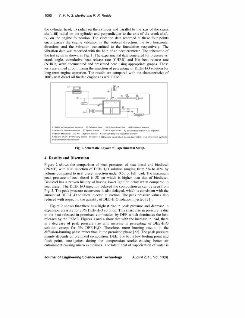
1090 Y. V. V. S. Murthy and R. R. Reddy
Journal of Engineering Science and Technology August 2015, Vol. 10(8)
the cylinder head, ii) radial on the cylinder and parallel to the axis of the crank
shaft, iii) radial on the cylinder and perpendicular to the axis of the crank shaft,
iv) on the engine foundation. The vibration data recorded at these four points
encompasses the engine vibration in the vertical direction, the two horizontal
directions and the vibration transmitted to the foundation respectively. The
vibration data was recorded with the help of an accelerometer. The schematic of
the test setup is shown in Fig. 1. The experimental data generated for pressure vs.
crank angle, cumulative heat release rate (CHRR) and Net heat release rate
(NHRR) were documented and presented here using appropriate graphs. These
tests are aimed at optimizing the injection of percentage of DEE-H2O solution for
long-term engine operation. The results are compared with the characteristics of
100% neat diesel oil fuelled engines as well PKME.
4. Results and Discussion
Figure 2 shows the comparison of peak pressures of neat diesel and biodiesel
(PKME) with dual injection of DEE-H2O solution ranging from 5% to 40% by
volume compared to neat diesel injection under 0.50 of full load. The maximum
peak pressure of neat diesel is 58 bar which is higher than that of biodiesel.
Biodiesel has a proven history of having lower ignition delay when compared to
neat diesel. The DEE-H2O injection delayed the combustion as can be seen from
Fig. 2. The peak pressure occurrence is also delayed, which is consistent with the
amount of DEE-H2O solution injected at suction. The peak pressure values also
reduced with respect to the quantity of DEE-H2O solution injected [21].
Figure 2 shows that there is a highest rise in peak pressure and decrease in
expansion pressure for 20% DEE-H2O solution. This sharp rise in pressure is due
to the heat released in premixed combustion by DEE which dominates the heat
released by the PKME. Figures 3 and 4 show that with the increase in load, there
is a decrease of peak pressure rise with increase in percentage of DEE-H2O
solution except for 5% DEE-H2O. Therefore, more burning occurs in the
diffusion-burning phase rather than in the premixed phase [22]. The peak pressure
mainly depends on premixed combustion. DEE, due to its low boiling point and
flash point, auto-ignites during the compression stroke causing better air
entrainment causing micro explosions. The latent heat of vaporization of water is
Fig. 1. Schematic Layout of Experimental Setup.

Combustion Heat Rate Analysis of C.I. Engine with Secondary . . . . 1091
Journal of Engineering Science and Technology August 2015, Vol. 10(8)
absorbed during the combustion of main fuel PKME keeping the cylinder
temperature lower creating cooler combustion. Due to this, premixed combustion
is improved and better diffused combustion takes place with betterment of torque.
Fig. 2. Pressure vs. Crank Angle for
½ full load condition.
Fig. 3. Pressure vs. Crank Angle
for ¾ full load condition.
Fig. 4. Pressure vs. Crank Angle for full load condition.
4.1. Combustion heat rate analysis
The variation of heat release rate for different percentages of DEE-H2O injections
under varying load conditions is seen in Figs. 5 through 8. The heat release rate
mainly depends on ignition delay and injection timings. At 1/4th full load condition,
the heat release rate is more for diesel than for the biodiesel PKME due to the lower
heating value of biodiesel than neat diesel. Figure 5 shows that 5% DEE-H2O

1092 Y. V. V. S. Murthy and R. R. Reddy
Journal of Engineering Science and Technology August 2015, Vol. 10(8)
injection has a higher heat release rate because, at part loads, the gas temperature
inside the engine is low and hence, accumulation of more PKME in premixed zone
has taken place due to which the heat release rate is increased. Figure 6 shows that
20% DEE- H2O injection has higher heat release rate at half full load due to the
increase in ignition delay. This may be due to the poor vaporization of 20% DEE-H2O
solution. At higher loads, premixed combustion is decreased with simultaneous
improvement in diffused combustion as observed for 5% DEE-H2O solution. This is
due to the complete burning of DEE which creates micro explosions in the solution
leading to improve the swirl in the combustion chamber, due to which the ignition
delay is decreased and higher heat is released, which can be seen in Figs. 7 and 8.
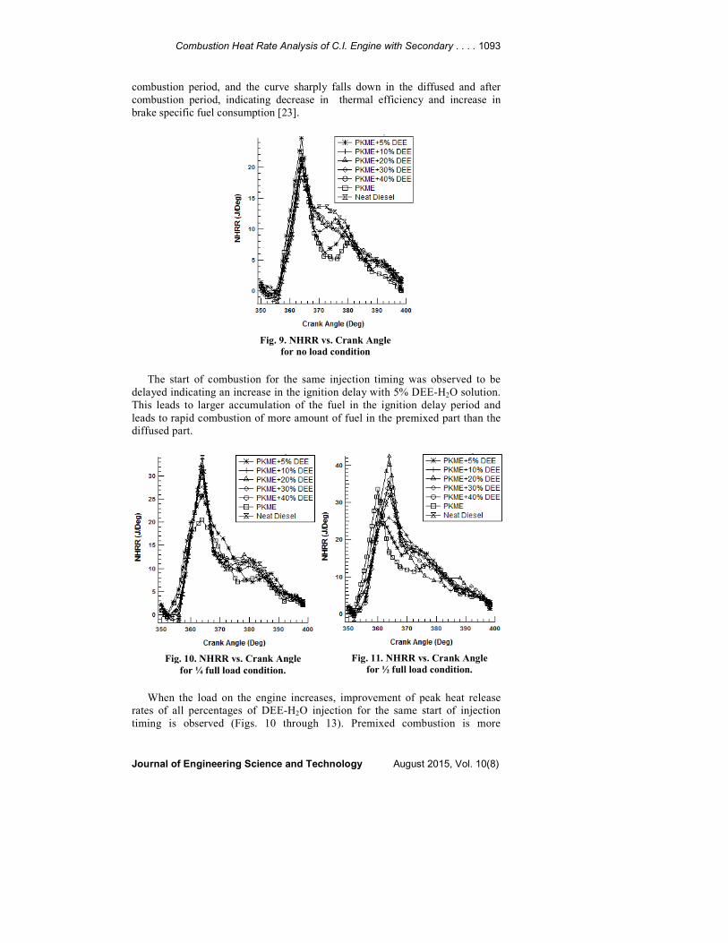
Figures 9 through 13 show the variation of net heat release rate with increase
in load for different percentages of DEE-H2O injection timings. In Fig. 9, the net
heat release rate starts decreasing with increase in the quantity of DEE-H2O
solution under no load conditions. We find that under no load conditions, 5%
DEE-H2O solution exhibits higher peak of heat release rate in premixed
Fig. 7. CHRR vs. Crank Angle
for ¾ full load condition.
Fig. 8. CHRR vs. Crank Angle
for full load condition.
Fig. 5. CHRR vs. Crank Angle
for ¼ full load condition.
Fig. 6. CHRR vs. Crank Angle
for ½ full load condition.
Combustion Heat Rate Analysis of C.I. Engine with Secondary . . . . 1093
Journal of Engineering Science and Technology August 2015, Vol. 10(8)
combustion period, and the curve sharply falls down in the diffused and after
combustion period, indicating decrease in thermal efficiency and increase in
brake specific fuel consumption [23].
The start of combustion for the same injection timing was observed to be
delayed indicating an increase in the ignition delay with 5% DEE-H2O solution.
This leads to larger accumulation of the fuel in the ignition delay period and
leads to rapid combustion of more amount of fuel in the premixed part than the
diffused part.
When the load on the engine increases, improvement of peak heat release
rates of all percentages of DEE-H2O injection for the same start of injection
timing is observed (Figs. 10 through 13). Premixed combustion is more
Fig. 9. NHRR vs. Crank Angle
for no load condition
Fig. 10. NHRR vs. Crank Angle
for ¼ full load condition.
Fig. 11. NHRR vs. Crank Angle
for ½ full load condition.

1094 Y. V. V. S. Murthy and R. R. Reddy
Journal of Engineering Science and Technology August 2015, Vol. 10(8)
prominent than the diffused combustion for higher loads for all percentages of
DEE-H2O injection except for 5% DEE-H2O injection. Figs. 12 and 13 show
that there is a decrease in intensity of premixed combustion for 5% DEE-H2O
injection. At 3/4th full load and full load conditions, intensity of premixed
combustion is well controlled for 5% DEE-H2O injection with the increased
area under the secondary peak, thus resulting in better torque conversion during
the piston slap mode.
Finally, the results obtained are summarized in terms of peak values
obtained for pressure, CHRR and NHRR for different blends at different loads.
Figures 2 to 13 show the changes in properties over crank angle. However, the
results can be better visualized by plotting the peak values obtained as shown in
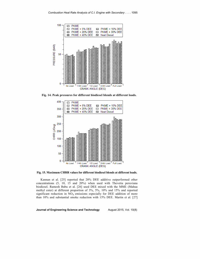
Figs. 14, 15 and 17. Figure 14 shows the peak pressure obtained at various
loads. While comparing the values of peak pressure of various biodiesel blends
with neat diesel, it can be observed that neat diesel has the lowest desired peak
pressure only at no load condition. At various load levels, atleast some of the
biodiesel blends performed better (lower peak pressure) than neat diesel.
However, there is little variation among all the fuels and there is no conclusive
evidence as to which biodiesel blend performs best in terms of peak pressure.
When comparing CHRR values from Fig. 15, it is clear that pure PKME always
had lower CHRR values than neat diesel. However, with the addition of DEE,
the biodiesel matched the maximum value of CHRR in almost all the cases. The
highest values of CHRR were obtained at lower concentrations of DEE (5%,
10% and 20%) as compared to higher concentrations (30 and 40%). Rao et al.
[24] reported the best values of peak pressure and heat release rate at 10%
additive among 5, 10, 15, 20 and 25% concentrations. However, they used
coconut biodiesel with triacetin (cetane improver) additive blends. NHRR
values for various fuels also do not show a clear trend. However, it can be seen
that some biodiesel blends perform sufficiently close to neat diesel.
Fig. 12. NHRR vs. Crank Angle
for ¾ full load condition.
Fig. 13. NHRR vs. Crank Angle
for full load condition.
Combustion Heat Rate Analysis of C.I. Engine with Secondary . . . . 1095
Journal of Engineering Science and Technology August 2015, Vol. 10(8)
Fig. 14. Peak pressures for different biodiesel blends at different loads.
Fig. 15. Maximum CHRR values for different biodiesel blends at different loads.
Kannan et al. [25] reported that 20% DEE additive outperformed other
concentrations (5, 10, 15 and 20%) when used with Thevetia peruviana
biodiesel. Ramesh Babu et al. [26] used DEE mixed with the MME (Mahua
methyl ester) at different proportion of 3%, 5%, 10% and 15% and reported
significant reduction in NOX emissions especially for DEE addition of more
than 10% and substantial smoke reduction with 15% DEE. Martin et al. [27]

1096 Y. V. V. S. Murthy and R. R. Reddy
Journal of Engineering Science and Technology August 2015, Vol. 10(8)
also reported that the addition of small quantities of DEE to cotton seed oil
(CSO) improved the performance of the diesel engine. When algal oil methyl
ester and its blends are used as a fuel, he best injection timing was found to be
340 crank angle degree with optimum performance, better combustion
characteristics and minimal emission [28]. In this work, optimum performance
was obtained between 360° and 400°. Looking at the results of various
researchers, it can be conclusively stated that biodiesel and biodiesel blends
perform well enough to warrant more research.
Fig. 16. Maximum NHRR values for
different biodiesel blends at different loads.
4.2. Vibration analysis
The vibration studies indicate that there is a tradeoff between the vibrations
recorded in different directions on the cylinder head. There is also a tradeoff
between the cylinder head vibration and the engine foundation vibration.
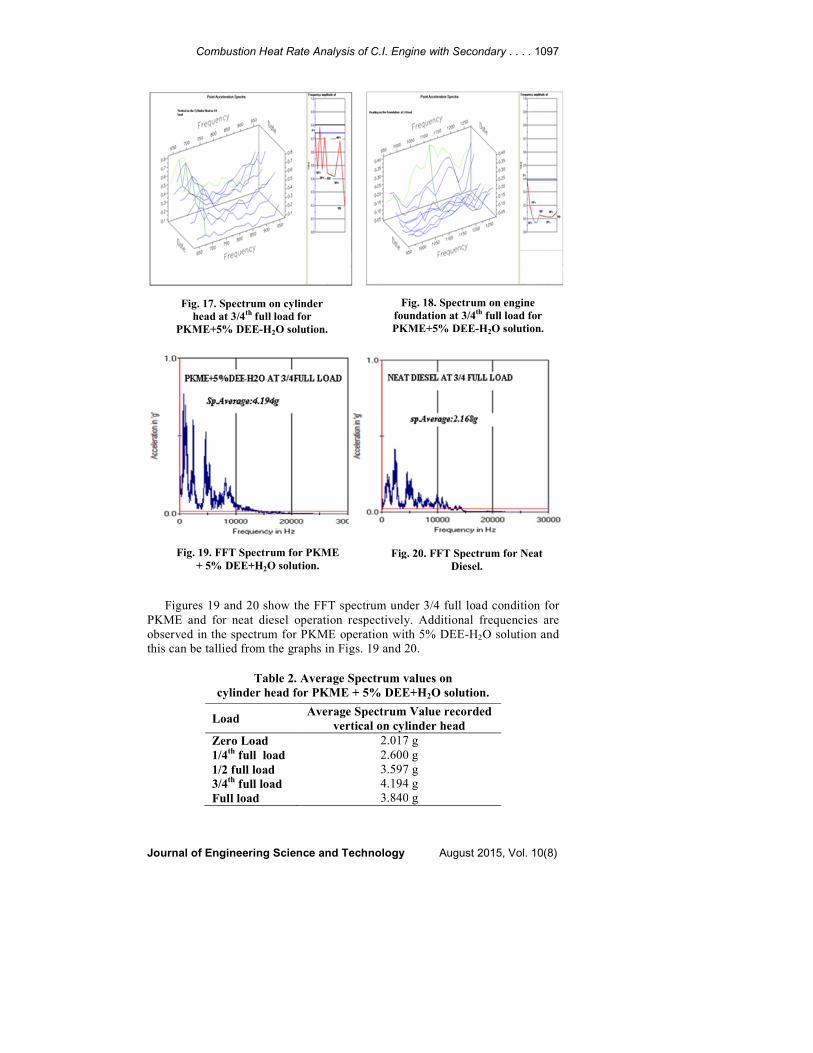
It can be observed from Figs. 17 and 18, for 5% DEE-H2O injection there is
an increase of vibration from cylinder head to the foundation. Since the
spectrum recorded on the cylinder head is the representative of the
combustion inside the cylinder, it can be assessed that a new mode of
combustion has taken place with different excitation frequencies in the
presence of DEE-H2O solution.
Combustion Heat Rate Analysis of C.I. Engine with Secondary . . . . 1097
Journal of Engineering Science and Technology August 2015, Vol. 10(8)
Figures 19 and 20 show the FFT spectrum under 3/4 full load condition for
PKME and for neat diesel operation respectively. Additional frequencies are
observed in the spectrum for PKME operation with 5% DEE-H2O solution and
this can be tallied from the graphs in Figs. 19 and 20.
Table 2. Average Spectrum values on
cylinder head for PKME + 5% DEE+H2O solution.
Load Average Spectrum Value recorded
vertical on cylinder head
Zero Load 2.017 g
1/4th full load 2.600 g
1/2 full load 3.597 g
3/4th full load 4.194 g
Full load 3.840 g
Fig. 17. Spectrum on cylinder
head at 3/4th full load for
PKME+5% DEE-H2O solution.
Fig. 18. Spectrum on engine
foundation at 3/4th full load for
PKME+5% DEE-H2O solution.
Fig. 19. FFT Spectrum for PKME
+ 5% DEE+H2O solution. Fig. 20. FFT Spectrum for Neat
Diesel.

1098 Y. V. V. S. Murthy and R. R. Reddy
Journal of Engineering Science and Technology August 2015, Vol. 10(8)
Fig. 21. Average accelerations at various loads
recorded vertical on cylinder head.
Table 2 and Fig. 21 show the average spectrum values recorded on the
cylinder head at various loads for PKME + 5% DEE-H2O solution. The
spectrum average value recorded for PKME + 5% DEE-H2O under 3/4 load
condition is 4.194 g (Fig. 19) but for neat diesel operation it is only 2.168 g
(Fig. 20). This is because of better combustion due to the enhanced swirl
created by complete vaporization of DEE-H2O solution leading to complete
lean combustion. It was observed that there is an increase in vibration from the
cylinder head to the engine foundation with higher injection rates of DEE-H2O
solution. The DEE-H2O solution has created split frequency combustion in the
range defined i.e. at 10,000 Hz. 3D graphs have been drawn for different ranges
of frequencies and the instant amplitudes in that duration for different DEE-
H2O solution ratings have been studied. It is observed that with the increase in
the percentage of DEE-H2O solution, the vibration values have decreased as can
be observed from the 3-D graphs from Fig. 14 and Fig. 15. On most occasions,
the neat diesel has produced lower values of vibration comparatively at all
loads. Fig. 14 depicts that in the crucial frequency range of 650-700Hz, the
amplitude raise is abnormal to the tune of 0.8 g at 3/4 full load of the engine for
5% DEE-H2O injection. This can be attributed to better torque conversion at
this percentage and also the average spectrum value at this percentage is 4.194
g, which is also an indication of better torque conversion.
Higher vibration levels on the foundation of the engine depend on the modal
vibration of the structure for a particular kind of excitation during combustion
which changes with the kind of fuel used. The vibration in the direction of
piston slap and the vibration transmitted to the foundation of the engine are
usually complementary. Higher torque conversion normally creates more
vibration isolation at the foundation. 5% DEE-H2O solution is one such
combination which delivered less vibration at engine foundation. The time
Combustion Heat Rate Analysis of C.I. Engine with Secondary . . . . 1099
Journal of Engineering Science and Technology August 2015, Vol. 10(8)
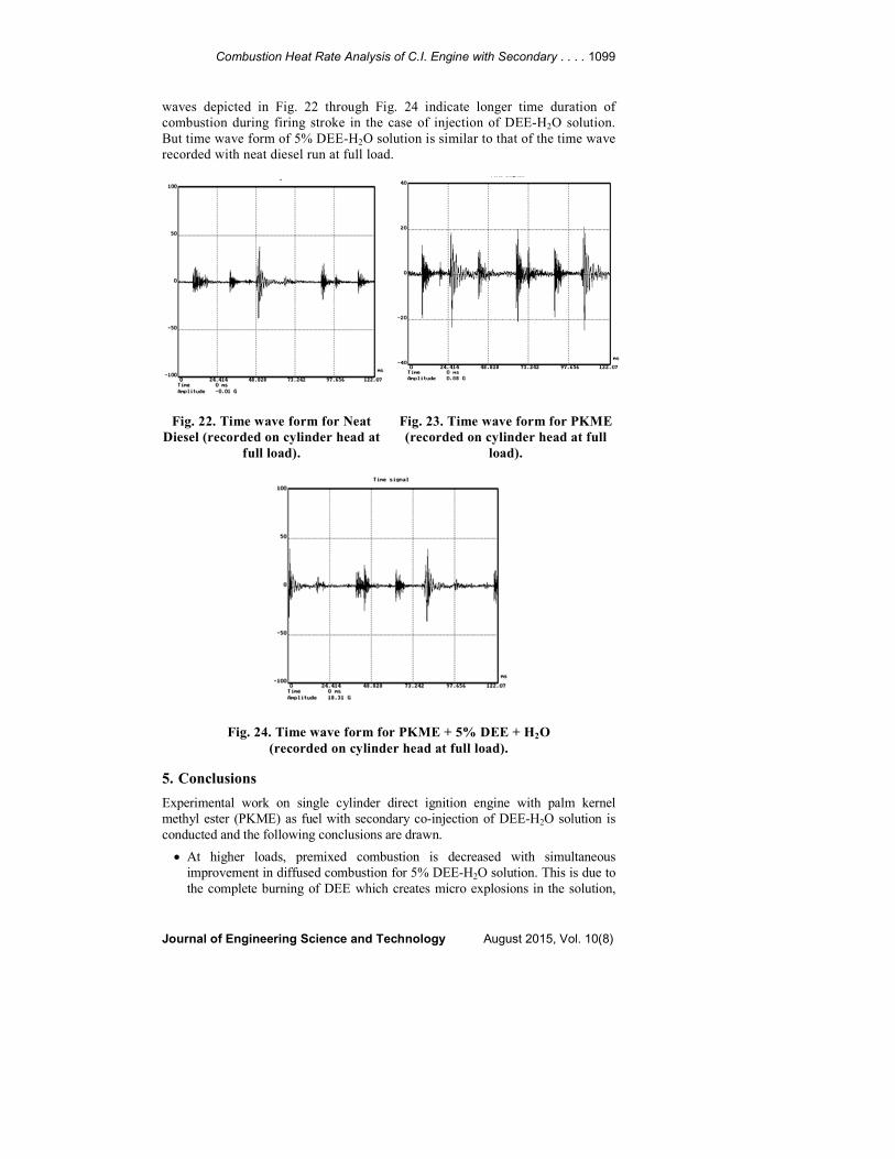
waves depicted in Fig. 22 through Fig. 24 indicate longer time duration of
combustion during firing stroke in the case of injection of DEE-H2O solution.
But time wave form of 5% DEE-H2O solution is similar to that of the time wave
recorded with neat diesel run at full load.
Fig. 22. Time wave form for Neat
Diesel (recorded on cylinder head at
full load).
Fig. 23. Time wave form for PKME
(recorded on cylinder head at full
load).
Fig. 24. Time wave form for PKME + 5% DEE + H2O
(recorded on cylinder head at full load).
5. Conclusions
Experimental work on single cylinder direct ignition engine with palm kernel
methyl ester (PKME) as fuel with secondary co-injection of DEE-H2O solution is
conducted and the following conclusions are drawn.
• At higher loads, premixed combustion is decreased with simultaneous
improvement in diffused combustion for 5% DEE-H2O solution. This is due to
the complete burning of DEE which creates micro explosions in the solution,

1100 Y. V. V. S. Murthy and R. R. Reddy
Journal of Engineering Science and Technology August 2015, Vol. 10(8)
leading to improvement of the swirl in the combustion chamber, due to which
the ignition delay is decreased and higher heat is released.
• Premixed combustion is more prominent than the diffused combustion for
higher loads for all percentages of DEE-H2O injection except for 5% DEE-
H2O injection.
• There is a decrease in intensity of premixed combustion for 5% DEE-H2O
injection at 3/4th full load and full load conditions. Intensity of premixed
combustion is well controlled for 5%DEE-H2O injection with the increased
area under the secondary peak, resulting in better torque conversion during
the piston slap mode.
• For 5% DEE-H2O injection, there is an increase in vibration from the
cylinder head to the engine foundation form no load condition to ¾ full load
except for full load condition. However it is always advisable that engine
should run at load lesser than the full load conditions.
• The combustion pattern has changed with the injection of DEE-H2O solution.
• The vibration spectrum was analyzed for the frequencies up to 10,000Hz.
Addition of DEE in water has created a change in vibration spectrum and a
split frequency was observed in the frequency range of 10000 Hz. It has been
observed from the 3-D graphs that with the increase in the percentage of
DEE-H2O solution, the vibration values have decreased.
• In the critical low frequency range of 650-700Hz, the amplitude rise is
abnormal to the tune of 0.8 g at 3/4 Full load of the engine for 5%DEE-H2O
injection. This can be attributed to better torque conversion at this
percentage, and also the average spectrum value at this percentage is 4.194 g,
which is also an indication of better torque conversion.
• There is a similarity of time wave forms for 5% DEE-H2O and engine run on
neat diesel run at full load condition.
• On the whole, the combustion analysis and vibration studies indicate that
PKME with 5% DEE-H2O secondary co-injection is the best combination.
References
1. Daly, D.T.; and Nag, P. (2001). Combustion modeling of soot reduction in
diesel and alternate fuels using CHEMKIN. SAE Technical Paper, 2001-
01-1239.
2. Lanzafame, R. (1999). Water injection effects in a single-cylinder CFR
engine. SAE Technical Paper Series, 1999-01-0568.
3. Subramanian, K.A.; and Ramesh, A. (2002). Use of diethyl ether along with
water-diesel emulsion in a DI-diesel engine. SAE Technical Paper, 2002-01-
2720.
4. Mack, J.H.; Flowers, D.L.; Buchholz, B.A.; and Dibble, R.W. (2004).
Investigation of HCCI combustion of diethyl ether and ethanol mixtures
using Carbon 14 tracing and numerical simulations. 30th International
Symposium on Combustion, Chicago, Illinois.
5. Akshatha, D.S.; Manavendra. G.; and Kumarappa, S. (2013). Performance
evaluation of Neem biodiesel on CI engine with diethyl ether as additive.

Combustion Heat Rate Analysis of C.I. Engine with Secondary . . . . 1101
Journal of Engineering Science and Technology August 2015, Vol. 10(8)
International Journal of Innovative Research in Science, Engineering and
Technology, 2(8).
6. Pugazhvadivu, M.; and Rajagopan, S. (2009). Investigations on a diesel
engine fuelled with biodiesel blends and diethyl ether as an additive. Indian
Journal of Science and Technology, 2(5), 31-35.
7. Nagdeote, D.D.; and Deshmukh, M.M. (2012). Experimental study of diethyl
ether and ethanol additives with biodiesel-diesel blended fuel engine.
International Journal of Emerging Technology and Advanced Engineering,
2(3), 195-199.
8. Jegadheesan, C.; Somasundaram, P.; Meenakshipriya, B.; and Vignesh, U.P.
(2013). Effect of DEE injection in Pongamia Pinnata biodiesel fulled CI
engine using hydrogen as secondary fuel. Advanced Materials Research, 768,
188-194.
9. Ali, O.M.; Mamat, R.; and Faizal, C.K.M. (2013). Effects of diethyl ether
additives on palm biodiesel fuel characteristics and low temperature flow
oroperties. International Journal of Advanced Science and Technology, 52,
111-120.
10. Taghizadeh-Alisaraei, A. (2012). Vibration analysis of a diesel engine using
biodiesel and petrodiesel fuel blends. Fuel, 102, 414-422.
11. Manorathna, R.P.; and Nanayakkara, N.K.B.M.P. (2011). Experimental
investigation of operating characteristics of bio-diesel on a conventional
diesel engine. International Journal of Innovation, Management and
Technology, 2(3), 199-203.
12. Ilic, Z.; Rasuo, B.; Jovanovic, M.; and Jankovic, D. (2013). Impact of
changing quality of air/fuel mixture during flight of a piston engine aircraft
with respect to vibration low frequency spectrum. FME Transactions, 41(1),
25-32.
13. Sitnik, L.; Magdziak-Toklowicz, M.; and Wrobel, R. (2011). Comparative
analysis of the vibrations of a different kind of engine mounted in the same
new motor vehicles. Journal of KONES Powertrain and Transport, 18(4).
14. Ramachandran, T.; and Padmanadhan, K.P. (2012). Review on Internal
combustion engine vibrations and mountings. IJESET, 3(1), 63-73.
15. Klinchaeam, S.; Nivesrangsan, P.; and Lokitsangthong, M. (2009). Condition
monitoring of a small four-stroke petrol engine using vibration signals.
KMITL Sci. Tech. Journal, 9(1), 9-17.
16. Lus, T.; and Lutowicz, M. (2010). Marine diesel engines diagnostics.
Research papers of Lithuanian University of Agriculture, 42(2-3), 141-149.
17. Chiatti, G.; Chiavola, O.; and Recco, E. (2013). Combustion and vibration
characteristics in a small displacement diesel engine fuelled with biodiesel
blends. SAE Technical Paper, 2013-01-1902.
18. Heidary, B.; Hassan-beygi, S.R; Ghobadian, B.; and Taghizadeh, A. (2013).
Vibration analysis of a small diesel engine using diesel-biodiesel fuel blends.
Agric Eng Int: CIGR Journal, 15(3), 117-126.
19. Satyanarayanamurthy, Y.V.V. (2011). Combustion analysis and knock
detection in single cylinder DI-diesel engine using vibration signature
analysis. International Journal of Engineering Science and Technology, 3(1),
10-16.

1102 Y. V. V. S. Murthy and R. R. Reddy
Journal of Engineering Science and Technology August 2015, Vol. 10(8)
20. Satyanarayanamurthy, Y.V.V. (2012). Experimental investigations of real
time secondary co-injection of water-diethyl ether solution in DI-diesel
engine fueled with palm kernel methyl ester. Journal of Engineering Science
and Technology, 7(6), 711-721.
21. Abdalla, A.Y.; Radwan, M.S.; and Ahmed, S.H. (1991). Smoke level and
operational roughness of a pre- combustion chamber diesel engine running
on gasoil/methanol blends. SAE Technical Paper, 912358.
22. Devan, P.K.; and Mahalakshmi, N.V. (2009). Study of the performance,
emission and combustion characteristics of a diesel engine using poon oil-
based fuels. Fuel Processing Technology, 90(4), 513-519.
23. Senthil Kumar, M.; Ramesh, A.; and Nagalingam, B. (2003). Use of
hydrogen to enhance the performance of a vegetable oil fuelled compression
ignition engine. International Journal of Hydrogen Energy, 28(10), 1143-
1154.
24. Rao, P.V.; and Rao, B.V.A. (2012). Heat release rate calculations and
vibration analysis of DI-diesel engine operating with coconut oil methyl
ester-triacetin additive blends. The IUP Journal of Mechanical Engineering,
5(2), 43-57.
25. Kannan, T.K.; and Marappan, R. (2011). Effects of injection timing on the
performance and emissions of a diesel engine fuelled with diethyl ether
blended thevetia peruviana biodiesel. International Journal of Energy
Technology and Policy, 7(5-6), 455-468.
26. Ramesh Babu, P.; Prasad Rao, K.; and Appa Rao, B.V. (2012). The role of
oxygenated fuel additive (DEE) along with Mahuva methyl ester to estimate
performance and emission analysis of DI-diesel engine. International Journal
of Thermal Technologies, 2(1), 119-123.
27. Martin, M.L.J. (2012). A comparative analysis of different methods to
improve the performance of cotton seed oil fuelled diesel engine. Fuel, 102,
372-378.
28. Hariram, V.; and Kumar. M.G. (2012). The Effect of injection timing
on combustion, performance and emission parameters with AOME blends as
a fuel for compression ignition engine. European Journal of Scientific
Research, 79(4), 653-665.