heat transfer in boilers heat engines & boilers. combustion chamber calculation radiation heat...
TRANSCRIPT

Heat transfer in boilers
Heat Engines & Boilers
Combustion chamber calculation
• Radiation heat transfer
• Adiabatic flame temperature
• Heat transfer in combustion chamber
• Retention time in fire chamber
• Flame size variation

Heat transfer forms from gas to solid surfaceConvection Radiation
By means of Fluid flow and conduction through
boundary layer
Electromagnetic radiation
Contact in between gas and solid
surface
Necessary Not necessary
(even in vacuum)
Depends mainly on Fluid flow type
and velocity
Temperature difference
raising to the 4th power
Equilibrium state
Q = 0
In case of equal temperature
T1 = T2
Even in case of different temperatures
T1 T2
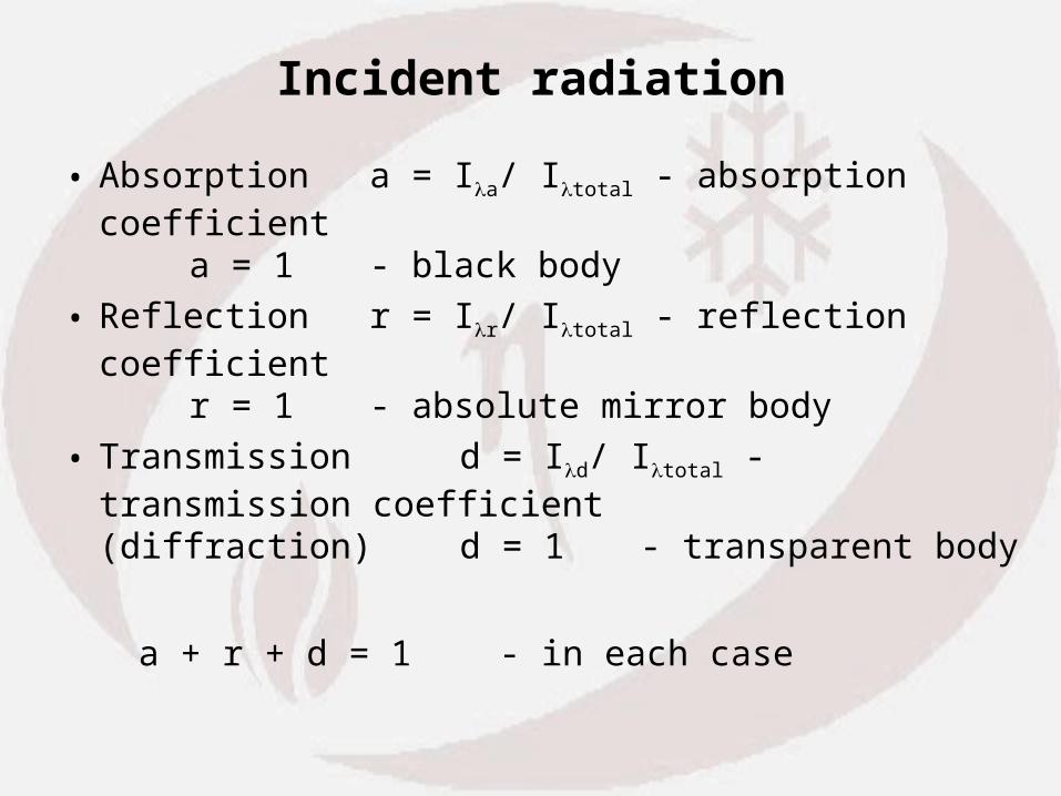
Incident radiation
• Absorption a = Ia/ Itotal - absorption coefficienta = 1 - black body
• Reflection r = Ir/ Itotal - reflection coefficientr = 1 - absolute mirror body
• Transmission d = Id/ Itotal - transmission coefficient(diffraction) d = 1 - transparent body
a + r + d = 1 - in each case
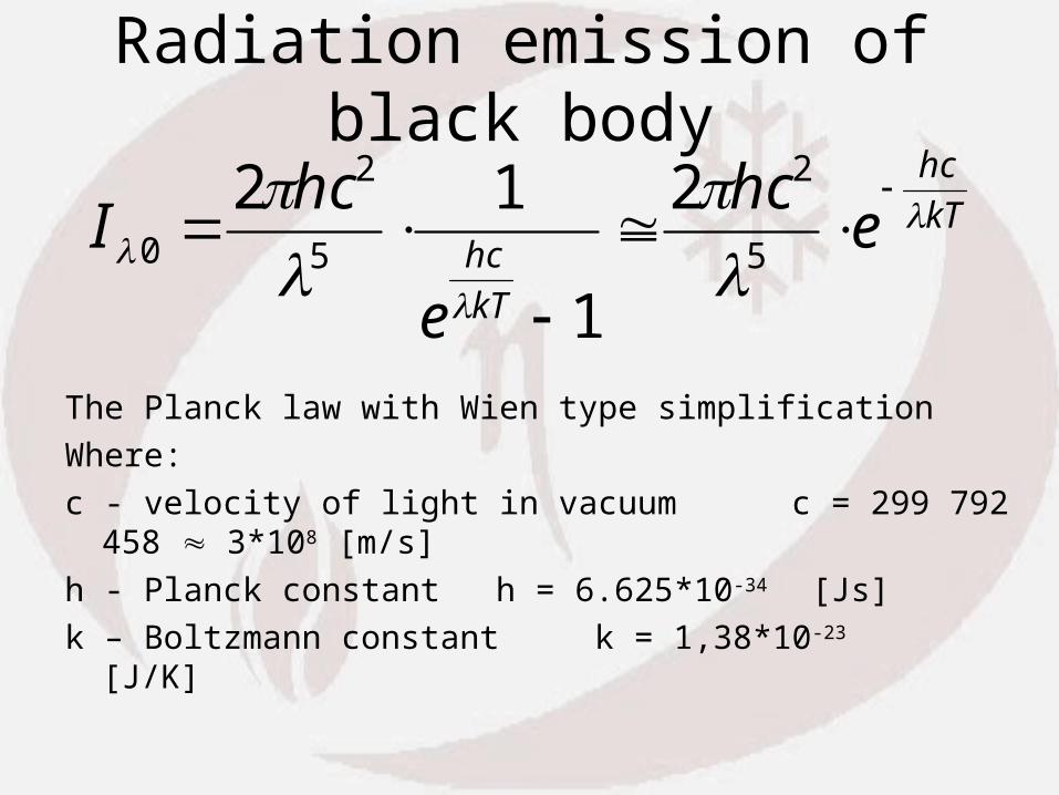
Radiation emission of black body
The Planck law with Wien type simplification
Where:
c - velocity of light in vacuum c = 299 792 458 3*108 [m/s]
h - Planck constant h = 6.625*10-34 [Js]
k – Boltzmann constant k = 1,38*10-23 [J/K]
kT
hc
kT
hc ehc
e
hcI
5
2
5
2
0
2
1
12
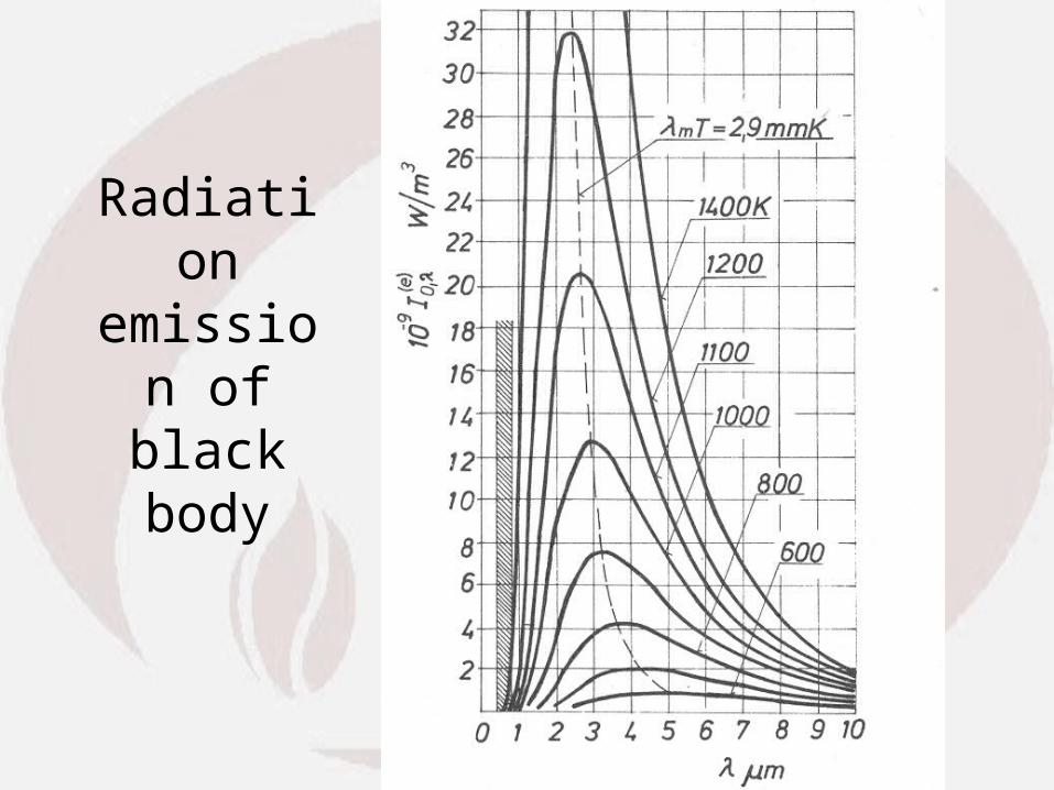
Radiation emission of black
body

Radiation energy density of black-body -
- Stefan-Boltzman law
• where:
- Stefan-Boltzman constant
E I d Ts
4
0
5 6787 10 8. W / m K2
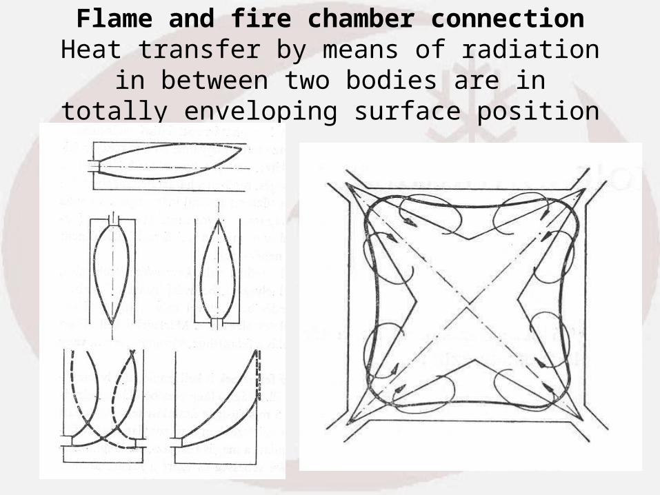
Flame and fire chamber connectionHeat transfer by means of radiation in between two
bodies are in totally enveloping surface position

Heat transfer by radiation
• where: - Emissivity factor
• A - effective water wall surfaces subject to radiation; [m2]
• Tf - average flame temperatur [K]
• Tw - average wall temperature [K]
[kW] TTAQ4
w
4
ffwr
fw
f w
11 1
1
fw

Emissivity factor variation in real
1. Black body - theoretical maximum2. Grey body - solid body radiation
emissivity is constant 3. Color body - gas radiation emissivity is not constant

Combustion process in real
Parallel procedures running at the same time
having dependence on one another:
• Chemical reaction
• Fluid flow
• Heat transfer
Simplification model:
1. Chemical reaction happens first
2. Hot flue-gas radiates heat
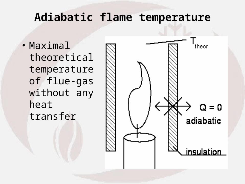
Adiabatic flame temperature
• Maximal theoretical temperatureof flue-gas without any heat transfer

Calculation of adiabatic flame temperature
• Heat flow into the combustion chamber:
• adiabatic flame temperature
• where: - B: mass flow rate of fuel [ kg/s]
• - v: specific flue gas amount, [kgfluegas/kgfuel] considering excess air and flue-gas recirculation
• - cpfg: mean specific heat of flue gas [kJ\kg K]
Q B H c t c tin i Lo pair hotair fuel fuel
pfgv
in0 cB
Qt

Heat balance in combustion chamber
Qr = Qin - Qfgout
Outlet flugas heat capacity
where:
fgout0pfgv
4w
4ffw TTcBTTA
Q B c tfgout v pfg fgout
fgoutof TTT
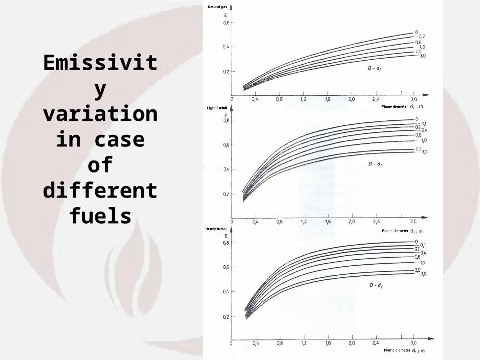
Emissivity variation in
case of different
fuels

Flame size variation

Flame size variation
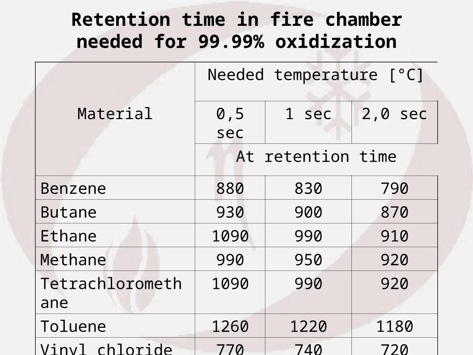
Retention time in fire chamberneeded for 99.99% oxidization
Needed temperature [°C]
Material 0,5 sec 1 sec 2,0 sec
At retention time
Benzene 880 830 790
Butane 930 900 870
Ethane 1090 990 910
Methane 990 950 920
Tetrachloromethane 1090 990 920
Toluene 1260 1220 1180
Vinyl chloride 770 740 720

Retention time calculation
s V
V = t
fg
ccret
where: tret = retention time [s],
Vcc = combustion chamber volume [m3],
Vfg = volume flow of flue gas [m3/s].
,fgV
dV = dt
Adx = dV
dxTV
273A =
V
dV = dt
,fgN
,fgN
Integrated from x=0 to x=xout
fgout
0
fgout0,fgN
ccret T
Tln
TTV
V273t

Summary of combustion chamber calculation
You are already familiar with:
• Radiation heat transfer
• Adiabatic flame temperature
• Heat transfer in combustion chamber
• Flame size variation
• Retention time in fire chamber

Convective heat transfer calculation
• Definition of convective surfaces
• Types and arrangements of convective heating surfaces
• Calculation method
• Heat balance
• Radiation / Convective heat transfer variation

Definition
• We call “Convective Heating Surfaces” surfaces which are built in the boiler after the combustion chamber until the boiler exhaust. Where heat transfer happens mainly by combustion:
• These can be:• - superheater• - evaporator• - water heater (economizer)• - combustion air heater• Each heating surface can not be found in every boiler.

Flue-gas flow can be inside tubes
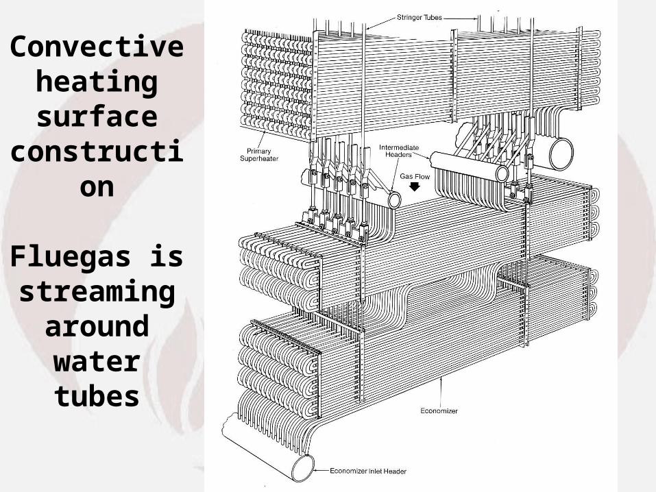
Convective heating surface
construction
Fluegas is streaming
around water tubes

Convective heating surface construction
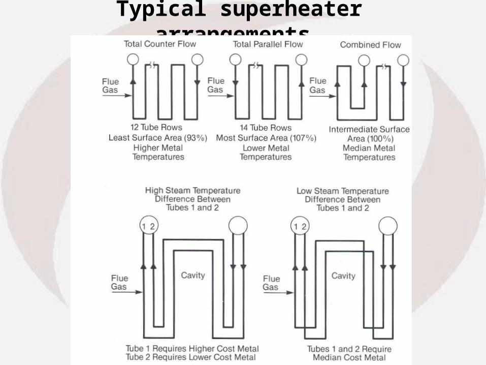
Typical superheater arrangements
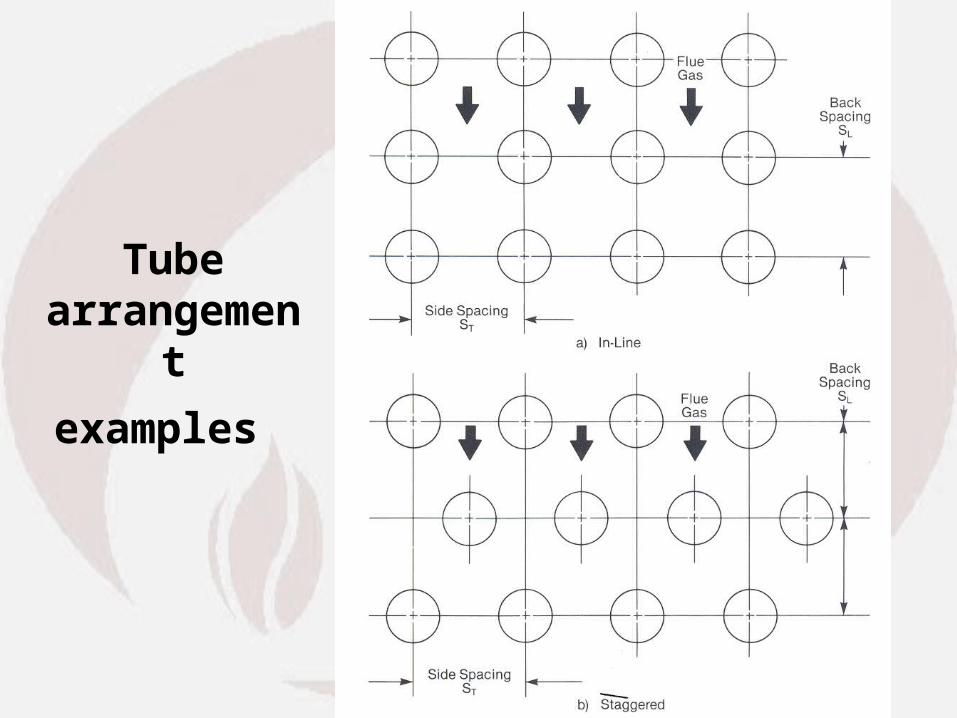
Tube arrangement
examples
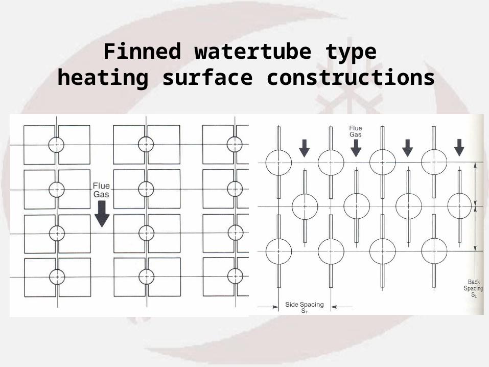
Finned watertube type heating surface constructions
Heat transfer calculation
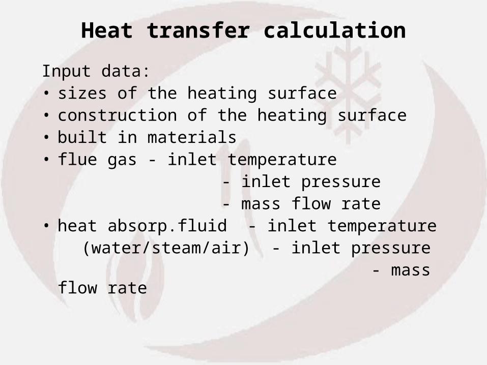
Input data:• sizes of the heating surface• construction of the heating surface• built in materials• flue gas - inlet temperature - inlet pressure - mass flow rate• heat absorp.fluid - inlet temperature (water/steam/air) - inlet pressure - mass flow rate

Iteration process
• Outlet temperature of the flue gas and the heat absorption fluid has to be estimated. Then average temperatures can be calculated
• flue gas:
• heat abs.fluid:
fgfgin fgout2
tt t
wwin wout2

Characteristic features
• Knowing the average temperatures you can determine the characteristic features belonging to the temperature and pressure both of the flue gas and the heat abs. fluid, which is needed to the calculation.
These can be:• density • thermal conductivity • Prandtl number Pr• specific heat cp
• kinematic viscosity • etc.

Heat transfer coefficient calculation
There are several semi empirical equation to determine heat transfer coefficient. For this dimensionless numbers are used. Most commonly used dimensionless numbers:
- Nusselt number: NuL
- Reynolds number Rew L
- Prandtl number Pr a
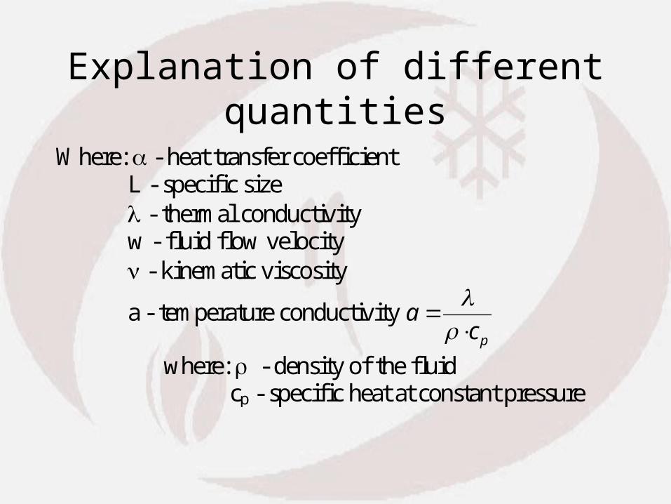
Explanation of different quantities
Where: - heat transfer coefficient L - specific size - thermal conductivity w - fluid flow velocity - kinematic viscosity
a - temperature conductivity acp
where: - density of the fluid cp - specific heat at constant pressure
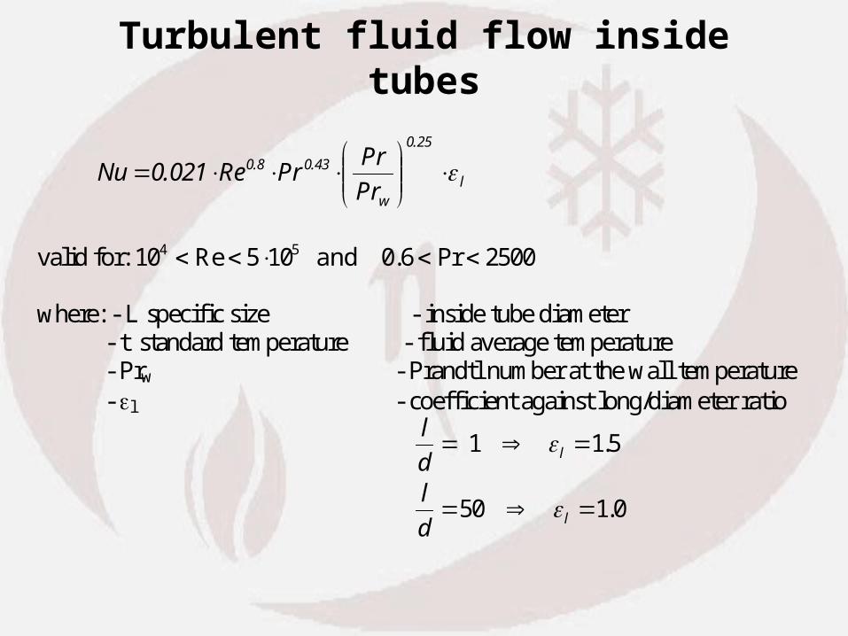
Turbulent fluid flow inside tubes
l
25.0
w
43.08.0
Pr
PrPrRe021.0Nu
valid for: 10 5 10 0 6 25004 5 Re . Pr and where: - L specific size - inside tube diameter - t standard temperature - fluid average temperature - Prw - Prandtl number at the wall temperature - l - coefficient against long/diameter ratio
l
dl
d
l
l
1 1 5
50 1 0
.
.
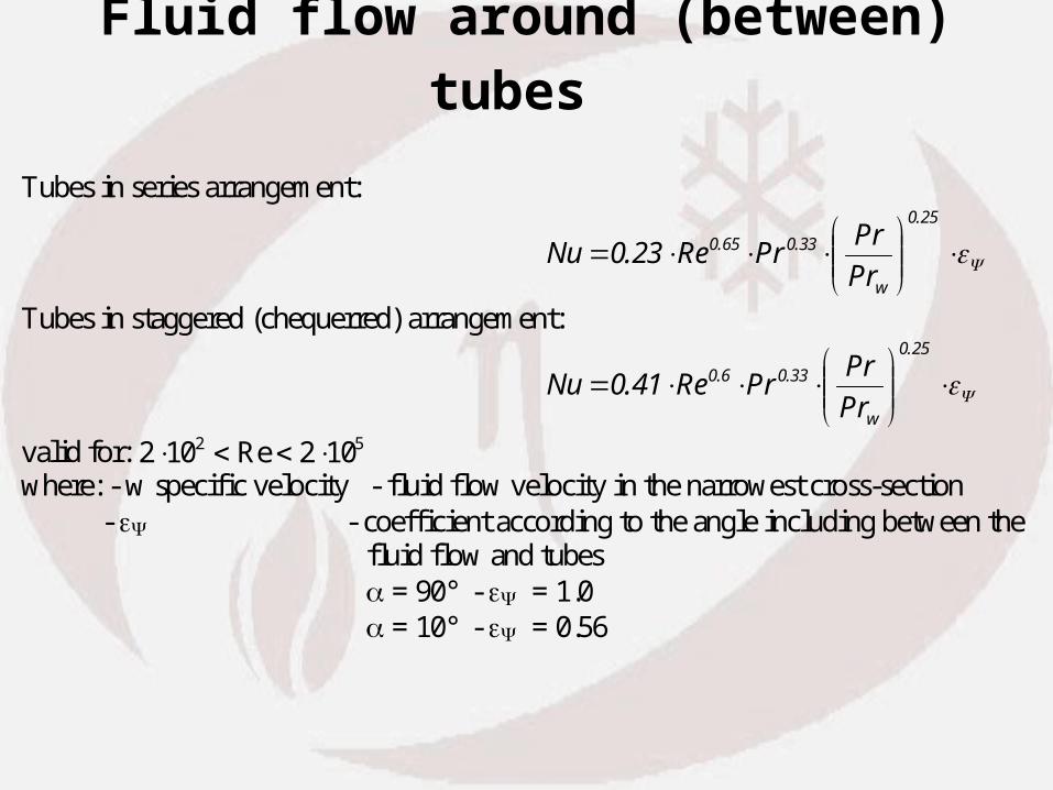
Fluid flow around (between) tubes
Tubes in series arrangement:
25.0
w
33.065.0
Pr
PrPrRe23.0Nu
Tubes in staggered (chequerred) arrangement:
25.0
w
33.06.0
Pr
PrPrRe41.0Nu
valid for: 2 10 2 102 5 Re where: - w specific velocity - fluid flow velocity in the narrowest cross-section - - coefficient according to the angle including between the fluid flow and tubes = 90° - = 1.0 = 10° - = 0.56

Heat transfer coefficient in case of water boiling
2 8 0 176 0 7. . .p q [W / m K ]2 valid at: 0.2 bar < p < 98 bar
1 27 0 75. .q e [W / m K]p
62 2 valid at: 6.0 bar < p < 173 bar
where - p - saturated pressure [bar] - q - heat flux [W/m2]

Ranges of heat transfer coefficients
These are only examples.
According to the surface arrangement you can find several cases in the literature.
Heat transfer coefficient has different value range at different types of fluid:
• In case of: water boiling: 5000 < < 20000 W/m2K• In case of water flow: 500 < < 2000 W/m2K• In case of steam flow: 100 < < 1000 W/m2K• In case of air or flue gas: 10 < < 200 W/m2K

Heat transmission coefficient Heat transmission coefficient
K][W/m 11
1 2
wi
i
fg
U
where: fg - flue gas heat transfer coefficient w - water/steam side heat transfer coefficient - thickness of the tube or other surface (In case of soot or scale coating possibility also has to be taken into account.) - thermal conductivity

Convective heat transfer
)(
)(
)(
)(
2
21
1
mWm
WW
Wfgfg
mfg
tt
tt
tt
ttUq

Convective heat transfer modification in case of deposit formation
flue gas side medium side
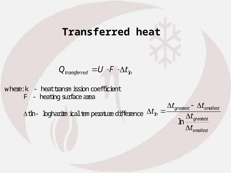
Transferred heat
lntFUQ dtransferre
where: k - heat transmission coefficient F - heating surface area
tln- logharitmical temperature difference
tt t
t
t
greatest smallest
greatest
smallest
ln
ln

Simple heat balance
Three types of heat quantities have to be equal: Q Q Qfg transferred water steam /
Flue gas heat:
C][ etemperatur gas flue - t
K][kJ/kg gas flue of heat specific- c
[kg/s] fuel of rate flow mass specific-
[kg/s] fuel of rate flow mass - B :where
[kW] ttc BQ
fg
pfg
'v
fgoutfginpfg'vfg
Water/steam:
[kJ/kg]enthalpy am water/ste- h
[kg/s]or water steamof rate flow mass - m :where
[kW] hhmQ
w
w
winwoutwsteam/water
Radiation / Convective heat transfer variation
• Radiation and convective heat transfer has different principal
• Radiation heat transfer is proportional with ~T4
• Convective heat transfer is proportional with velocity
• In case of part load operation less fuel is burnt- less fuel produce less fluegas on same cross section gives less velocity- combustion reaction temperature remains nearly the same
• Consequently radiation/convection heat transfer ratio increases with power load decrease

Summary of convective heat transfer calculation
You are already familiar with• Definition of convective surfaces• Types and arrangements of convective heating
surfaces• Calculation method• Heat balance• Radiation / Convective heat transfer variation• (see calculation example)

Thank You for Your Attention !
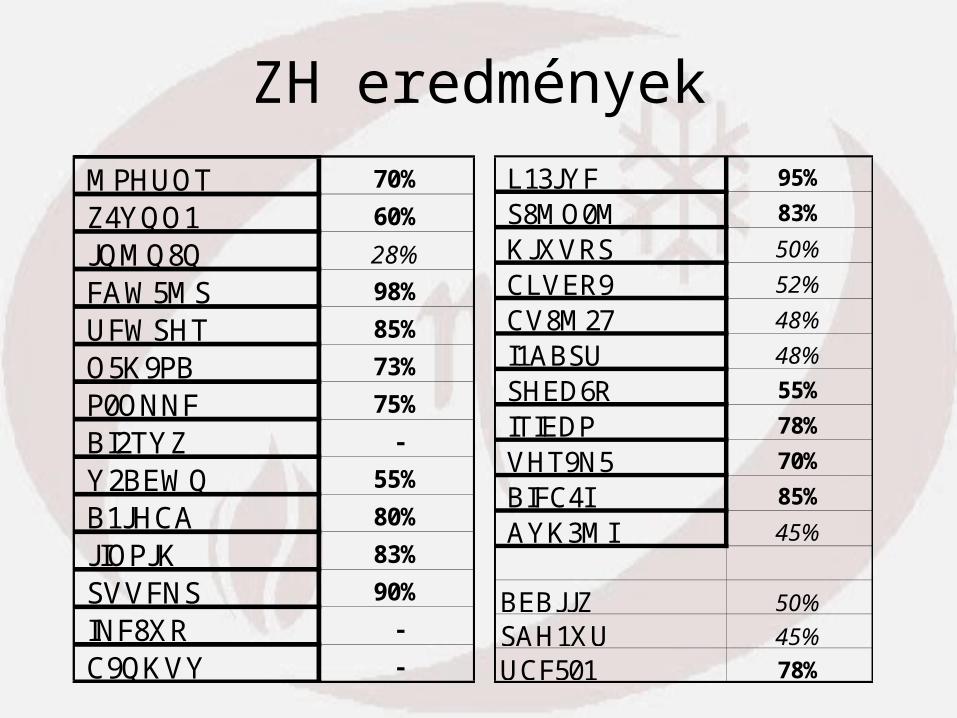
ZH eredmények L13JYF 95%
S8MO0M 83%
KJXVRS 50%
CLVER9 52%
CV8M27 48%
I1ABSU 48%
SHED6R 55%
ITIEDP 78%
VHT9N5 70%
BIFC4I 85%
AYK3MI 45%
BEBJJZ 50%
SAH1XU 45%
UCF501 78%
MPHUOT 70%
Z4YQO1 60%
JQMQ8Q 28%
FAW5MS 98%
UFWSHT 85%
O5K9PB 73%
P0ONNF 75%
BI2TYZ -
Y2BEWQ 55%
B1JHCA 80%
JIOPJK 83%
SVVFNS 90%
INF8XR -
C9QKVY -