combined power quality and condition monitoring of ... · combined power quality and condition...
TRANSCRIPT
Combined Power Quality and Condition Monitoring of Offshore
MV and HV Cable Networks
By
Dr Lee Renforth, Dr Malcolm Seltzer-Grant,
Steve Goodfellow &
Marc Foxall
HVPD Ltd Manchester, UK
Main Contact:
Dr Lee Renforth
Managing Director, HVPD Ltd
2/15
ABSTRACT
It is understood (from discussions with UK offshore wind farm operators and the insurance industry) that medium voltage (MV) and high voltage (HV) cable faults presently make up around 90% of offshore wind farm insurance claims made to date. It is also reported that many of these claims relate to cable insulation faults occurring either during the construction and commissioning phase or during the first 2-3 years of service. This is the ‘infant mortality’ phase of the reliability centred maintenance (RCM) ‘bathtub curve’. The UK Government’s Department of Energy and Climate Change (DECC) have stated that they require the (presently high) operational and maintenance (O&M) costs to fall by 25% by 2020 to make this offshore renewables electricity more affordable to the UK consumer. DECC have published a Levelised Cost of Electricity (LCOE) model that predicts the total cost over the 20-year lifetime of the asset. This predicts a present cost of £135 per MWh generated for a ‘typical’ 500MW+ offshore wind farm with DECC placing a target of bringing this below £100 per MWh generated (a reduction of 25%). This can only be achieved by reducing the presently very high O&M costs, particularly those costs associated with unplanned outages caused by cable faults. The authors propose that in order to achieve this reduction in O&M costs a radical rethink of existing offshore HV network asset management practices is needed by the offshore wind farm operators through the use of ‘holistic’ condition monitoring (CM) solutions. It is through the use of ‘holistic’ condition monitoring (CM) technology that preventative maintenance interventions can be targeted to ‘incipient’ faults on the network, to allow the operator to be ‘ahead of the game’. The paper presents an overview of some of the electrical condition monitoring (CM) solutions that are being developed by the HVPD and our partners in the offshore renewables industry. These technologies include a new offshore high voltage AC network Monitoring System (OHVMS) for AC MV and HV cable networks and a new On-line High Voltage Direct Current Condition Monitor (OLPD-HVDC) for HVDC cable networks. The paper includes a case study of a project involving on-line partial discharge (OLPD) measurement techniques is presented, including an example of PD diagnostic testing on a 13km-long, 33kV land-sea export cable to a UK offshore wind farm. This case study shows how the diagnostic, condition monitoring data from OLPD testing and monitoring enabled the wind farm operator to implement preventative maintenance intervention to avoid an unplanned outage, providing a cost saving to the operator in excess of £250,000.

3/15
1. Introduction
It is understood (from discussions with UK offshore wind farm operators and insurors) that medium voltage (MV) and high voltage (HV) cable faults presently make up around 90% of offshore wind farm insurance claims made to date from the ‘Round 1’ and ‘Round 2’ offshore wind farms. It has also been reported that many of these cable faults have occurred during the construction and commissioning phase with these failures caused by a number of reasons including due poor cable installation practices (causing mechanical damage to cable sheaths), poor design (not robust enough for the offshore environment) and also poor workmanship (badly made-up MV/HV cable accessories such as joints and terminations). Prior to failure, these ‘incipient’ cable insulation faults can produce partial discharge (PD) activity, transient earth faults (TEF’s) and high sheath currents with localised heating of the cable (depending on the cause of the ‘incipient’ fault). All of these pre-failure characteristics can be monitored on-line with the cable remaining in-service using on-line partial discharge (OLPD), TEF and sheath current condition monitoring (CM) modules. Such CM systems can provide the operator with a sufficient ‘early warning’ of the incipient faults to implement condition based management (CBM) through preventative maintenance to avoid unplanned outage. A case study of a project involving OLPD measurement techniques is presented, including an example of PD diagnostic testing on a 13km-long, 33kV land-sea export cable to a UK offshore wind farm. The paper includes recommendations as to how the presently high O&M costs in the offshore renewables markets could be reduced with a move towards condition-based management (CBM) using real-time (continuous) diagnostic intelligence on both the state and condition of the offshore MV/HV networks. These ‘holistic’ monitoring approaches would include OLPD, TEF, sheath current, power quality, weather/tidal data, power flow, and overvoltage/overcurrent events, with cross correlation of all of these parameters seen as the key to any health/risk diagnostic assessment.
Figure 1: A UK 60MW ‘Round 1’ Offshore Wind Farm
4/15
2. The ‘Drivers’ for On-line Condition Monitoring of MV and HV Subsea Cables
The reliability of the high-value, high criticality HV and MV subsea export and the MV inter-array cables are clearly essential for the effective operation of the offshore renewables facilities. The purpose of any on-line cable condition monitoring system is to provide an advanced, ‘early warning’ against insulation faults in order that planned, preventative maintenance can be carried out to avert unplanned outages (that can cost from £250,000 upwards to several million £’s, depending on the location of the fault).
Due to the technically challenging nature of these offshore MV/HV cable networks, it should be noted that the cost of an unplanned outage from a subsea cable fault offshore can be anything from 10x to 100x of the cost of the same cable failure onshore. The subsea MV and HV cables have the following, common characteristics:
They require long (and expensive) repairs and/or long replacement lead times.
The repairs are expensive to do as a cable lift/repair vessel is required.
Unplanned outages are much more expensive than scheduled, preventative maintenance during planned outages (typically by a factor of at least 10x).
Operators need to ensure the networks have high reliability, good maintainability and maximum availability.
It is known from past projects that a large proportion of these incipient insulation faults can be detected prior to an earth fault occurring and this can be achieved most effectively by using a combination of cable state and condition monitoring technologies. Such a ‘holistic’ cable condition monitoring (CM) system should provide for the early-stage detection of partial discharge activity (PD), power quality/harmonic issues, circulating sheath currents, transient earth faults and overvoltage events. The advantages of continuous on-line condition monitoring of the in-service cables are:
The diagnostic can be made without the need for an outage.
The cable is assessed under normal (and abnormal) operating conditions.
The data can be used to support Condition-Based Maintenance (CBM) to predict and prevent failures by the detection of ‘incipient’ cable faults.
The techniques ensure the continuous, reliable operation of the cable networks by reducing downtime, unplanned outages, site visits and lowering O&M costs
3. MV and HV Cable Failure Rate Data for Offshore Wind Farm Networks
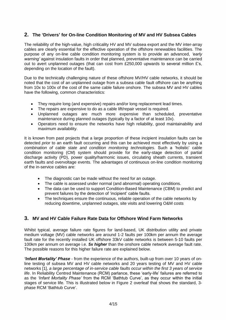
Whilst typical, average failure rate figures for land-based, UK distribution utility and private medium voltage (MV) cable networks are around 1-2 faults per 100km per annum the average fault rate for the recently installed UK offshore 33kV cable networks is between 5-10 faults per 100km per annum on average i.e. 5x higher than the onshore cable network average fault rate. The possible reasons for this higher failure rate are explained below. ‘Infant Mortality’ Phase - from the experience of the authors, built-up from over 10 years of on-line testing of subsea MV and HV cable networks and 20 years testing of MV and HV cable networks [1], a large percentage of in-service cable faults occur within the first 3 years of service life. In Reliability Centred Maintenance (RCM) parlance, these ‘early-life’ failures are referred to as the ‘Infant Mortality Phase’ from the RCM ‘Bathtub Curve’, as they occur within the initial stages of service life. This is illustrated below in Figure 2 overleaf that shows the standard, 3-phase RCM ‘Bathtub Curve’.
5/15
Such an ‘infant mortality’ phase is typical for new technology introductions, this having been observed already in the offshore wind market where the wind turbine OEM’s have suffered high levels of early stage the mechanical and gearbox failures. This is also seen where known technology is applied to a new market sector (in this case subsea MV and HV cable technology) where high levels of infant mortality failures occur due to a lack of experience held by the offshore wind farm operators in the application of the established technology. As the main knowledge base for the reliable operation of subsea MV and HV cables is held in the oil & gas industry it is necessary to have some knowledge transfer from experiences gained in this mature market to meet the specific issues of the new offshore renewables market. It is also known from the UK offshore industry that many of the cable failures to date have occurred during the construction and commissioning stage and then within the first 2-3 years of service. These faults have been due to a combination of poor cable installation practices (causing mechanical damage), poor design (insufficient for the seabed environment) and poor workmanship (badly made-up MV/HV cable accessories such as joints and terminations). Many of the in-service cable faults typically occur at the cable accessories (cable joints and terminations) and are normally caused as a result of incorrect installation of these accessories (which are ‘made-up’ on site).
Figure 2: RCM ‘Bathtub Curve’ Showing the 3 Main Phases
Mechanical and Environmental Effects from the Sea – it is known that another reason for the higher failure rate of subsea MV/HV cables is due to the additional mechanical, abrasion and vibration effects of subsea cables moving with the tides and currents. This leads to mechanical damage at subsea connectors and joints and also external abrasion of the outer jacket of the cables leading to sheath faults from the outside of the cable. These mechanical and environmental stressing factors, in conjunction with the infant mortality issues discussed above, are the reasons why subsea HV cable networks require a higher level of condition monitoring than their land-based equivalents.
Failu
re R
ate
Time
Phase 2: Steady State
Failure
Phase 3: End of Life ‘Wear-out’
Phase 1: Infant
Mortality
RCM ‘Bathtub Curve’
3 Years 20-50 Years

6/15
4. What are the Weak Points within the Subsea MV and HV Cable Networks
In-service cable failure experiences from past projects carried out by the authors have shown that the most likely points of failure of the subsea cables are at the cable accessories i.e. the cable joints and terminations. The weak points for a land-sea export cable are illustrated below in Figure 3.
Figure 3: The ‘Weak Points’ in a MV/HV Land-Sea Export Cable
The causes of various types of cable insulation faults are numerous and include effects from the following list of ‘TEAM’ stresses:
Thermal – Electrical - Ambient – Mechanical Thermal – ‘thermal runaway’ problems can occur in the cable in cases where the design or installation of the cross-bonding or earthing bonds (at cable joints) is not carried out correctly, leading to a high resistance point with corresponding localised heating. Electrical - the No.1 cause of cable faults occurring within the first 3 years of service is incorrect installation of cable accessories (which produces internal partial discharge (PD) activity, tracking and then full insulation breakdown in cable joints and cable terminations). Ambient – in the case of subsea cables, this refers to the effects mechanical wear, tear and abrasion caused by movement of the subsea cables with tidal and current changes e.g. the subsea cable can covered/uncovered on the seabed with tidal/current changes. Mechanical - many subsea cable failures can be attributed to inadequate mechanical protection of the cables for duty in the sea. This problem can be avoided with good mechanical protection system design including heavy gauge armouring and roll-bar cages. In many cases, subsea cable systems fail due to ‘under designed’ cable components which can fail due to a combination of the above underlying ‘TEAM’ stresses. Prior to failure, many ‘incipient’ cable insulation faults produce PD activity which can be detected and located (‘mapped’) on-line, with the cable remaining in service. This technique can then enable the owner to carry out preventative maintenance to avoid unplanned outages. Some photos of defective 33kV cable accessories are shown in Figure 4 below.
Land Termination
(Indoor/Outdoor)
Subsea Termination
(Indoor)
Land-Subsea
Cable JointLand
Cable Joint
Land Cable Subsea Cable

7/15
Figure 4: Some Examples of Insulation Faults in a 33kV Land-Sea Export Cables
5. Specific ‘Drivers’ for the Offshore Wind Farm Renewables Industry
Today, the UK has around 2GW of installed offshore wind generation capacity, this being the largest of any country in the world. Plans are in place to increase this present capacity in the UK tenfold (up to 20GW+) by 2020, including a raft of large-size ‘Stage 3’ projects presently in the planning phase (this includes the proposed 9GW wind farm at Dogger Bank in the North Sea). The first round of small-scale (30-100MW) offshore windfarm ‘demonstrator’ sites were installed between 2005-2010, typically consisting of a small number of turbines (10 to 30), located relatively close to shore (<15km), with 33kV inter array and 33kV land-sea export cables. The second round of medium size, (500MW+) offshore installations that are being completed, commissioned or built (including the recently installed London Array wind farm) are larger, consisting of 33kV inter array cables and 132kV land-sea export cables with offshore 132kV GIS substations, as shown below in Figure 5.
Figure 5: Illustration of a typical ‘Round 2’ (500MW+) UK Offshore Wind Farm MV & HV Network.

8/15
UK ‘Round 3’ offshore wind farms, such as the proposed 9GW wind farm at Dogger Bank in the North Sea, will require a High Voltage Direct Current (HVDC) export cable link due to the high power and long distance from shore (125km). Offshore wind generation is presently the most expensive of the various renewable energy options (the Government’s Department of Environmental and Climate Change, DECC’s LCOE (levelised cost of electricity) model predicts a total cost of £135/MWh generated (for a 500MW+ Round 3 offshore wind farm) over the expected 20-year lifetime of the assets. It is interesting also to note also that the lowest-cost renewable energy option at the present time is onshore wind generation (at around 40% the offshore LCOE cost). The UK has now fully committed to offshore wind energy as the main source of our future renewables to meet targets set-out in the Kyoto Protocol and the European Plan on Climate Drive of 20% of the EU’s energy consumption from renewable sources by 2020. DECC have identified that a reduction in the high operating and maintenance (O&M) costs of the offshore wind farms is essential to drive down costs and to make this source of renewable electricity more affordable to the consumer. In fact DECC have put a target of reducing the total cost of offshore wind generation by 25%, from the present estimated cost of around £135/MWh to £100/MWh, by 2020. This will be quite an engineering and asset management challenge! The offshore renewables industry has already stated that they now require more proactive on-line monitoring and predictive tools to allow their asset and operations managers to better schedule maintenance, detect issues early and reduce (or ideally look to eliminate) unplanned outages from MV and HV cable faults altogether. However, it is the opinion of the authors that, these cost reductions will only be achievable through a radical rethink on present asset management practice, with a move towards condition-based management (CBM) essential. Furthermore, it is also argued that for effective CBM to be implemented, detailed, real-time (continuous) diagnostic intelligence and data on both the state and the condition of the MV and HV subsea cable networks is required. This is partly due to the higher-than-expected number of insulation faults which occurred on the Round 1 and Round 2 wind farm land-sea cable installations (which were installed between 2005-2012) and also due to the high ‘criticality’ of the export cable links to shore.
6. Reducing Insurance Costs for Offshore Renewables Insurance
Unplanned outages from cable faults can lead to significant down time and lost revenue for the operators (and their insurers). This is particularly so if a subsea cable fault occurs during the winter months when repairs to subsea cables are not easy to arrange due to limited specialist vessel access offshore. For continued operational reliability, more effective risk management and to help reduce the presently high O&M costs, it is recommended that the offshore wind farm operators apply condition-based management (CBM) regimes to their cable networks. The efficacy of any CBM scheme will be largely dependent on the quality and reliability of the condition monitoring (CM) data from which resultant repair/replace/retain decisions are made. Therefore, in order to ensure effective CBM, there is a need for high-level, diagnostic state and condition data from the CM technology employed. Due to the high rate of ‘infant mortality’ problems with these cable networks observed, it is recommended that condition monitoring should start with the testing and commissioning of the new MV/HV cables components at installation (using portable HV power sources and diagnostic insulation condition testing). This testing can then be supplemented by continuous condition monitoring technology throughout the cables’ service life, with particular focus on the initial 3 years of service.
9/15
7. Overview of Holistic Cable Condition Monitoring Technologies
7.1 Offshore High Voltage Network Monitoring System (OHVMS) for AC Cables
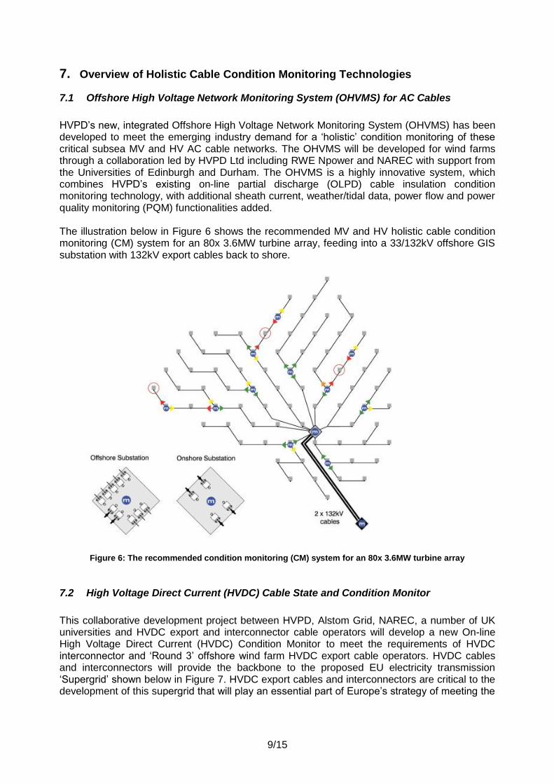
HVPD’s new, integrated Offshore High Voltage Network Monitoring System (OHVMS) has been developed to meet the emerging industry demand for a ‘holistic’ condition monitoring of these critical subsea MV and HV AC cable networks. The OHVMS will be developed for wind farms through a collaboration led by HVPD Ltd including RWE Npower and NAREC with support from the Universities of Edinburgh and Durham. The OHVMS is a highly innovative system, which combines HVPD’s existing on-line partial discharge (OLPD) cable insulation condition monitoring technology, with additional sheath current, weather/tidal data, power flow and power quality monitoring (PQM) functionalities added. The illustration below in Figure 6 shows the recommended MV and HV holistic cable condition monitoring (CM) system for an 80x 3.6MW turbine array, feeding into a 33/132kV offshore GIS substation with 132kV export cables back to shore.
Figure 6: The recommended condition monitoring (CM) system for an 80x 3.6MW turbine array
7.2 High Voltage Direct Current (HVDC) Cable State and Condition Monitor
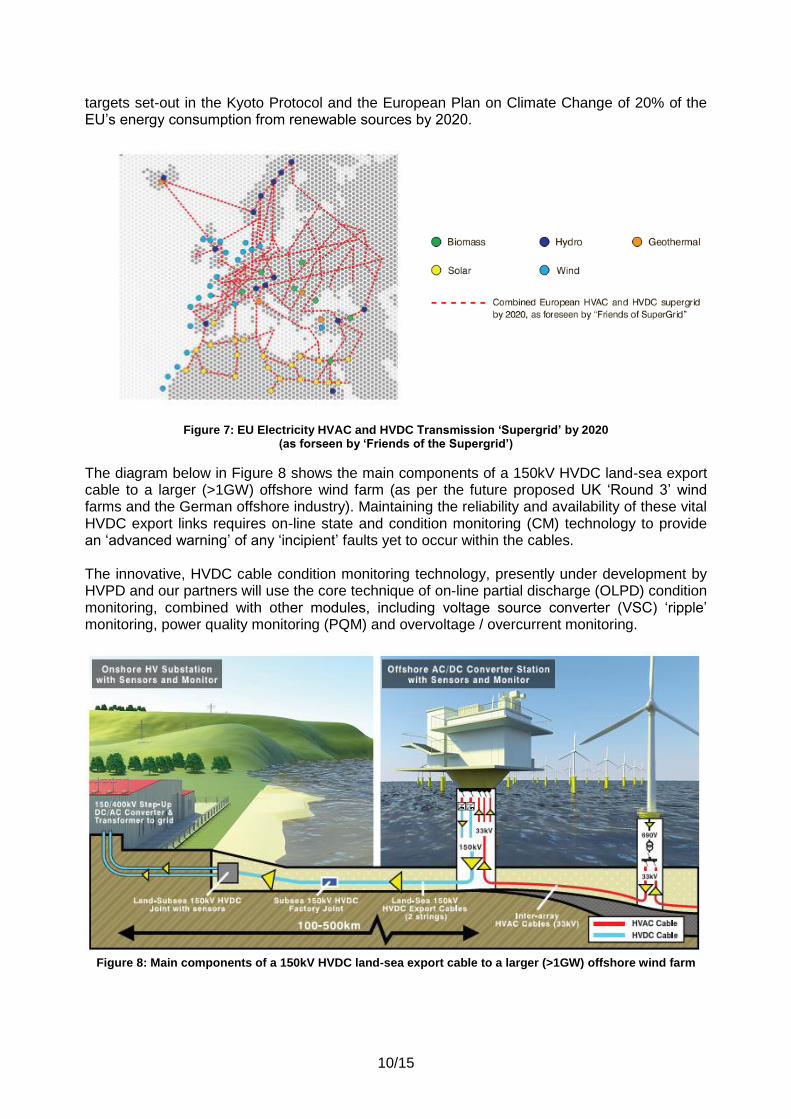
This collaborative development project between HVPD, Alstom Grid, NAREC, a number of UK universities and HVDC export and interconnector cable operators will develop a new On-line High Voltage Direct Current (HVDC) Condition Monitor to meet the requirements of HVDC interconnector and ‘Round 3’ offshore wind farm HVDC export cable operators. HVDC cables and interconnectors will provide the backbone to the proposed EU electricity transmission ‘Supergrid’ shown below in Figure 7. HVDC export cables and interconnectors are critical to the development of this supergrid that will play an essential part of Europe’s strategy of meeting the
10/15
targets set-out in the Kyoto Protocol and the European Plan on Climate Change of 20% of the EU’s energy consumption from renewable sources by 2020.
Figure 7: EU Electricity HVAC and HVDC Transmission ‘Supergrid’ by 2020 (as forseen by ‘Friends of the Supergrid’)
The diagram below in Figure 8 shows the main components of a 150kV HVDC land-sea export cable to a larger (>1GW) offshore wind farm (as per the future proposed UK ‘Round 3’ wind farms and the German offshore industry). Maintaining the reliability and availability of these vital HVDC export links requires on-line state and condition monitoring (CM) technology to provide an ‘advanced warning’ of any ‘incipient’ faults yet to occur within the cables. The innovative, HVDC cable condition monitoring technology, presently under development by HVPD and our partners will use the core technique of on-line partial discharge (OLPD) condition monitoring, combined with other modules, including voltage source converter (VSC) ‘ripple’ monitoring, power quality monitoring (PQM) and overvoltage / overcurrent monitoring.
Figure 8: Main components of a 150kV HVDC land-sea export cable to a larger (>1GW) offshore wind farm
11/15
8. On-line Partial Discharge (OLPD) Sensors and Monitoring Technology
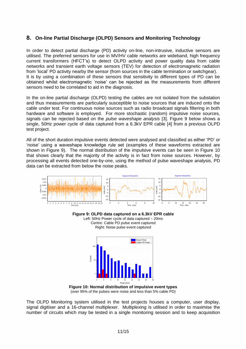
In order to detect partial discharge (PD) activity on-line, non-intrusive, inductive sensors are utilised. The preferred sensors for use in MV/HV cable networks are wideband, high frequency current transformers (HFCT’s) to detect OLPD activity and power quality data from cable networks and transient earth voltage sensors (TEV) for detection of electromagnetic radiation from ‘local’ PD activity nearby the sensor (from sources in the cable termination or switchgear). It is by using a combination of these sensors that sensitivity to different types of PD can be obtained whilst electromagnetic ‘noise’ can be rejected as the measurements from different sensors need to be correlated to aid in the diagnosis. In the on-line partial discharge (OLPD) testing the cables are not isolated from the substation and thus measurements are particularly susceptible to noise sources that are induced onto the cable under test. For continuous noise sources such as radio broadcast signals filtering in both hardware and software is employed. For more stochastic (random) impulsive noise sources, signals can be rejected based on the pulse waveshape analysis [3]. Figure 9 below shows a single, 50Hz power cycle of data captured from a 6.3kV EPR cable [4] from a previous OLPD test project. All of the short duration impulsive events detected were analysed and classified as either ‘PD’ or ‘noise’ using a waveshape knowledge rule set (examples of these waveforms extracted are shown in Figure 9). The normal distribution of the impulsive events can be seen in Figure 10 that shows clearly that the majority of the activity is in fact from noise sources. However, by processing all events detected one-by-one, using the method of pulse waveshape analysis, PD data can be extracted from below the noise peaks.
Time (ms)
20191817161514131211109876543210
Ch
an
1 (
V)
0.015
0.01
0.005
0
-0.005
-0.01
-0.015
Segment Waveform
Time uSec
1086420
Vo
lts (
mV
)
15
10
5
0
-5
-10
-15
Segment Waveform
Time uSec
302520151050
Vo
lts (
mV
)
15
10
5
0
-5
-10
-15
Figure 9: OLPD data captured on a 6.3kV EPR cable Left: 50Hz Power cycle of data captured – 20ms
Centre: Cable PD pulse event captured Right: Noise pulse event captured
4 6 8 10 12 14 16 18 20
1
10
100
Co
un
ts
Peak (mV)
Noise Peak
Cable PD Peak
Figure 10: Normal distribution of impulsive event types (over 95% of the pulses were noise and less than 5% cable PD)
The OLPD Monitoring system utilised in the test projects houses a computer, user display, signal digitiser and a 16-channel multiplexer. Multiplexing is utilised in order to maximise the number of circuits which may be tested in a single monitoring session and to keep acquisition

12/15
hardware costs down. The unit has an onboard web interface which can be accessed on the unit or remotely via LAN or a GPRS/HSDPA modem. As with OLPD ‘spot’ measurements, data is captured from power-cycle duration blocks. After processing of the data, summary statistics are generated and saved. Notably the Peak: magnitude of largest pulse detected; Count: number of pulses of each category detected; Activity: the integrated sum of all pulses of that category (in nC/cycle for cable PD, mV/cycle for local PD/noise). By trending this pre-analysed diagnostic data, changes in the PD activity during the monitoring session can be observed. For example increases in PD peak indicate the defect is getting bigger and increases in PD count indicate defects discharging more rapidly over a wider area (from surface or interfacial tracking). The OLPD monitoring system and sensors described above is a good starting point for considering a more advanced, ‘holistic’, flexible and real-time diagnostic monitoring system. Feedback from discussions with the offshore wind farm operators has shown that they require a combined system that is capable of correctly identifying the state, condition and performance of their monitored MV/HV offshore networks. The operators are interested in monitoring for OLPD activity, power quality/harmonic issues, circulating sheath currents, transient earth faults and overvoltage events but require one system to do this (i.e. not 5 different ones).
9. PD Monitoring on 33kV Land-Sea Export Cables (Case Study)
The case study shows how on-line partial discharge (OLPD) testing, monitoring and mapping was used to direct a planned maintenance intervention on a 33kV land-sea export cable to an offshore UK wind farm. Following a number of insulation faults at cable joints on the land cable section of the 33kV export cable, it was decided to perform OLPD testing and short-term (1 week) monitoring to assess the insulation condition of 2x 33kV circuits (land section: 1.7km of 3x single core and subsea cable section: 11.1km of 3-core) as illustrated below in Figure 11.
Figure 11: 33kV Wind farm Export Cable
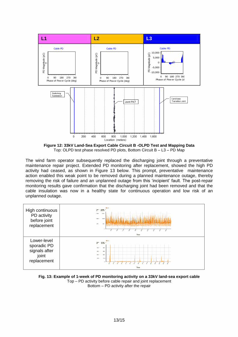
All circuits were tested from the on-shore substation. With high levels of PD (of up to 10,000pC/10nC) measured on Circuit B, L3 as shown by Figure 12 below (top). This was located (through OLPD mapping tests) to one joint (Joint 7) on this circuit B, L3 indicating a weak spot in the cable insulation at this location, as shown in Figure 12 (bottom).
33kV Switching
Substation
Offshore Wind
farm
Land-Subsea
Cable Joints
Land Cables 3 x single
core
Offshore 33kV
GIS Switchgear
33kV Grid Substation
3 core Subsea
Cables
Circuit 1 Circuit 2
13/15
L1 L2 L3
Cable PD
Phase of Pow er Cycle (deg)
360270180900
PD
Magnitu
de (
pC
)
0
Cable PD
Phase of Pow er Cycle (deg)
360270180900
PD
Magnitu
de (
pC
)
0
Cable PD
Phase of Pow er Cycle (deg)
360270180900
PD
Magnitu
de (
pC
) 10,000
5,000
0
-5,000
-10,000
Figure 12: 33kV Land-Sea Export Cable Circuit B -OLPD Test and Mapping Data
Top: OLPD test phase resolved PD plots, Bottom Circuit B – L3 – PD Map
The wind farm operator subsequently replaced the discharging joint through a preventative maintenance repair project. Extended PD monitoring after replacement, showed the high PD activity had ceased, as shown in Figure 13 below. This prompt, preventative maintenance action enabled this weak point to be removed during a planned maintenance outage, thereby removing the risk of failure and an unplanned outage from this ‘incipient’ fault. The post-repair monitoring results gave confirmation that the discharging joint had been removed and that the cable insulation was now in a healthy state for continuous operation and low risk of an unplanned outage.
High continuous PD activity before joint replacement
Lower-level sporadic PD signals after
joint replacement
Fig. 13: Example of 1-week of PD monitoring activity on a 33kV land-sea export cable Top – PD activity before cable repair and joint replacement
Bottom – PD activity after the repair

14/15
10. Discussion
This paper has set out some of the technical and financial drivers for the application of
‘holistic’ condition monitoring technology to the subsea MV and HV cable networks in the offshore wind farm industry. Such systems are of particular interest to the offshore wind farm operators and their insurers due to the high rate of ‘infant mortality’ cable failures that have been seen to date in the UK Round 1 and Round 2 installations.
The purpose of such an integrated state and condition monitoring platform is to provide an advanced ‘early warning’ against ‘incipient’ cable insulation faults to direct preventive maintenance to avert unplanned outages. From the practical point of view, this can be achieved through the detection of early-stage partial discharge (PD) activity, power quality issues (e.g. harmonics, dc currents, transient disturbances, etc.), sheath current, transient earth faults (TEF’s) and overvoltage events.
The increasing installation rate of offshore wind farms in Europe, combined with the high MV and HV cable fault rates reported in the UK, has led to a ‘market need’ for better condition monitoring (CM) technology. A move towards Condition Based Management (CBM) of the MV and HV subsea cable networks (using data from ‘holistic’ condition monitoring technologies) is the key to help reduce these O&M costs over the 20-year service life of these assets).
As the O&M costs in the offshore renewables markets are presently very high, cost reductions can only be achieved if there is a radical rethink on present asset management practice, with a move towards CBM viewed as essential.
For the subsea cable networks, a ‘holistic’ condition monitoring approach requires the integration of a number of complementary, cable-condition monitoring technologies. These could include some or all of the following partial discharge, distributed temperature sensing (DTS), cable sheath current, power quality monitoring (PQM), weather/tidal, power flow, and overvoltage/overcurrent events.
It is proposed that, it is only by the cross-correlation of all of these various condition and state parameters, that it will then be possible to provide the necessary level of detailed diagnostic data required for the cost-effective implementation and direction of both CBM and preventative maintenance schemes.
It can be noted that, due to the technically challenging nature of offshore HV networks, it is estimated that the cost of an unplanned outage as a result of a fault on an HVAC or HVDC cable offshore is typically between 10 to 50 times the cost of the same failures on an onshore cable. This underlines the importance for offshore wind farm operators (and their insurers) to understand the need for condition-based monitoring systems to help drive down the presently very high O&M costs.
From an engineering perspective, the next phase of larger and more remote ‘Round 3’ offshore wind farms will provide even greater technical challenges for engineers as they will include the installation of long-length (250km+) HVDC land-sea interconnection cables and offshore HV AC/DC conversion technology, all of these technologies place additional strain on the HV insulation within the cable networks.
15/15
11. Conclusions
For the offshore subsea MV andHV cable networks, it is proposed that a ‘holistic’ condition and state monitoring technology is employed that integrates a number of condition monitoring modules (including power quality, partial discharge, cable sheath current, weather/tidal data, power flow and overvoltage/overcurrent events). It is argued that it is only by cross-correlation of all of these various cable condition and state parameters that the necessary level of diagnostic data is achieved for the cost-effective implementation of condition based maintenance (CBM) schemes. Such a ‘holistic’ condition monitoring system would provide for the early detection, faster identification and efficient resolution (through preventative maintenence intervention) of ‘incipient’ cable faults.
References:
[1] R. Mackinlay and C. Walton, 2001, "Diagnostics for MV cables and switchgear as a tool
for effective asset management", Proceedings CIRED 2001.
[2] L. Renforth and Paul Hamer, 2012, “A New Technique for the Remote Partial Discharge
Monitoring of the Stator Insulation of High-Voltage Motors located in “Ex” (Hazardous)
Locations”, Proceedings IEEE-PCIC 2012 Conference.
[3] L. Renforth, R. Mackinlay and M. Seltzer-Grant, 2009, "Deployment of Distributed On-line
Partial Discharge Monitoring Devices on Medium Voltage Electricity Networks", Proceedings
CIRED 2007.
[4] Malcolm Seltzer-Grant, Denis Denissov, Ross Mackinlay, Frank Petzold, Lee Renforth and
Hubert Schlapp, 2011, “On-line Continuous PD Monitoring for In-service Distribution Class
Cables and Switchgear”. Proceedings CIRED 2011.
[5] Barry Howarth, Mark Coates and Lee Renforth 2006, “Fault Location Techniques for One
of the World’s Longest AC Interconnector Cables” IEE ACDC 2006 Conference Proceedings.