combine grain tank extension - demco products€¦ · introduction. page 3 ... location of such...
TRANSCRIPT

ASSEMBLYOPERATIONREPLACEMENT PARTS
PLACE IN COMBINE CAB AFTER ASSEMBLY FOR FUTURE REFERENCE.
Maurer Manufacturing, LLC • 1300 38th Ave. West • P.O. Box 160 • Spencer, IA 51301PH: (712) 262-2992 • FAX: (712) 262-1022 • www.maurermfg.com
Combine Grain Tank ExtensionJohn DEErE XL EXTEnsion
oPErATors / AssEmbLy mAnUALFiTs: ALL s680 & s690 CombinEs
2-6-20178E000034,Rev. AD

Page 2
GENERAL INFORMATION1. Read assembly instructions carefully. Study assem-
bly procedures and all illustrations before you begin assembly. Note which parts are used in each step. This unit must be assembled in proper sequence or complications will result.
3. Whenever terms “LEFT” and “RIGHT” are used in this manual it means from a position behind combine and facing forward.
2. When placing a parts order, refer to this manual for proper part numbers and place order by PART NO. and DESCRIPTION.
WARNING: TO AvOID PERSONAL INjURY OR DEATH, OBSERvE THE FOLLOWING INSTRUCTIONS:
Ensure that anyone present is clear before applying power to any machinery used in conjunction with a Maurer grain tank extension.
Never allow anyone in or near the grain tank of a combine during loading or unloading of grain. The accumulation of grain is dangerous and can cause entrapment, resulting in serious injury or death by suffocation.
Adding a Maurer Bin Extension or Tip-Up increases the overall height of your combine. Use caution when operating around trees, buildings, power lines, and when approaching bridges and over passes. Pay attention to height restrictions.
Do not exceed advertised maximum capacity of a Maurer grain tank extension.
Table of Contents General information............................................................................................................. 2 Safety, Signal Words ........................................................................................................... 3 Product Safety Guidelines................................................................................................... 4 Safety Sign Locations ......................................................................................................... 5 Safety Sign Care ................................................................................................................. 5 Product Disclaimer .............................................................................................................. 5 Extension Breakdown ......................................................................................................... 6 Extension Parts List ............................................................................................................ 7 Side Panel Assembly .........................................................................................................8-9 Foam Tape Installation ........................................................................................................ 9 Frame Assembly ................................................................................................................ 10 Panel Assembly................................................................................................................10-12 Light & GPS Bracket Mounting ......................................................................................... 12 Completed Grain Tank Assembly ....................................................................................... 13 Factory Extension Removal ............................................................................................... 14 Mounting Plates & Frame Spacers .................................................................................... 15 Mounting Instructions .......................................................................................................16-17 Tank Cap Installation ........................................................................................................18-19 Sensor & Light Wiring ....................................................................................................... 19 Corner Filler Angle Installation .........................................................................................20-21 Handrail Installation..........................................................................................................22-23
Thank you for purchasing a Maurer grain tank extension. Proper care and use will result in many years of service.
INTRODUCTION

Page 3
SAFETYTAKE NOTE! THIS SAFETY ALERT SYMBOL FOUND THROUGHOUT THIS MANUAL IS USED TO CALL YOUR ATTENTION TO INSTRUCTIONS INvOLvING YOUR PERSONAL SAFETY AND SAFETY OF OTHERS. FAILURE TO FOLLOW THESE INSTRUCTIONS CAN RESULT IN INjURY OR DEATH!
THIS SYMBOL MEANS
ATTENTION
BECOME ALERT
YOUR SAFETY IS INvOLvED!
SIGNAL WORDS Note use of following signal words DANGER, WARNING, and CAUTION with safety messages. The appropriate signal word for each has been selected using the following guidelines:
DANGER: Indicates an imminently hazardous situation that, if not avoided, will result in death or serious injury. This signal word is to be limited to most extreme situations typically for machine components which, for functional purposes, cannot be guarded.
WARNING: Indicates a potentially hazardous situation that, if not avoided, could result in death or serious injury, and includes hazards that are exposed when guards are removed. It may also be used to alert against unsafe practices.
CAUTION: Indicates a potentially hazardous situation that, if not avoided, may result in minor or moderate injury. It may also be used to alert against unsafe practices.
If you have questions not answered in this manual, require additional copies, or if your manual is damaged, please contact your dealer or Maurer Manufacturing, LLC; P.O. Box 160, 1300 38th Ave. West, Spencer, Iowa 51301, Ph: (712) 262-2992 Fax: (712) 262-1022 www.maurermfg.com
Page 4
EqUIPMENT SAFETY GUIDELINES
Every year many accidents occur which could have been avoided by a few seconds of thought and a more careful approach to handling equipment. You, the operator, can avoid many accidents by observing the following precautions in this section. To avoid personal injury, study the following precautions and insist those working with you, or you yourself, follow them.
Replace any caution, warning, danger or instruction safety decal that is not readable or is missing. Location of such decals is indicated in this booklet.
Review safety instructions with all users annually.
Operator should be a responsible adult. DO NOT ALLOW PERSONS TO OPERATE OR ASSEMBLE THIS UNIT UNTIL THEY HAvE DEvELOPED A THOROUGH UNDERSTANDING OF SAFETY PRECAUTIONS AND HOW IT WORKS.
Do not paint over, remove, or deface any safety signs or warning decals on your equipment. Observe all safety signs and practice instructions on them.
Never exceed limits of a piece of machinery. If it’s ability to do a job, or to do so safely is in question DON’T TRY IT.
Adding a Maurer Bin Extension or Tip-Up increases the overall height of your combine. Use caution when operating around trees, buildings, power lines, and when approaching bridges and over passes. Pay attention to height restrictions.
Fold and secure (if needed) the grain tank extension panels when transporting or hauling the combine to avoid contact with low power lines and other obstructions.
Use the panel safety step to safely enter and exit the grain tank.
Ensure that any additional bracing and safety equipment have been installed according to this manual. (Some models do not require additional bracing or safety equipment)
Ensure that the grain tank extension frame has been properly mounted to the combine according to this manual.
Never exceed the maximum advertised capacity of the grain tank extension. By doing so you risk damage to the grain tank extension.
Page 5
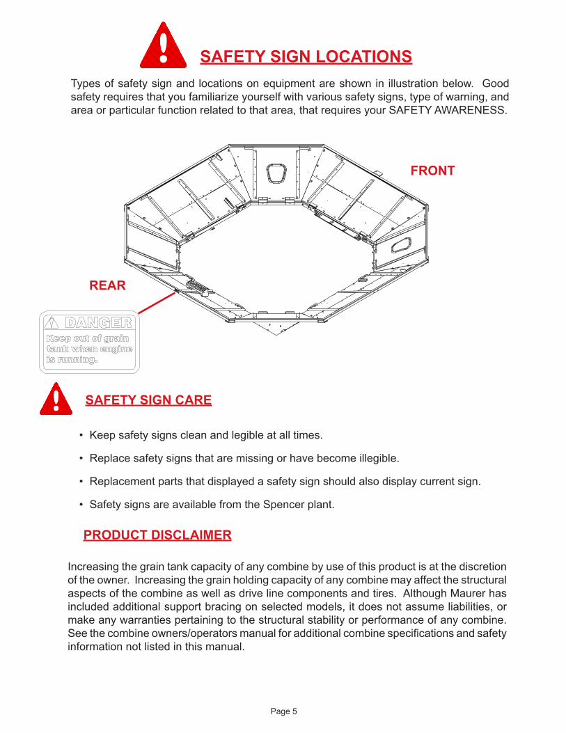
SAFETY SIGN LOCATIONSTypes of safety sign and locations on equipment are shown in illustration below. Good safety requires that you familiarize yourself with various safety signs, type of warning, and area or particular function related to that area, that requires your SAFETY AWARENESS.
SAFETY SIGN CARE
• Keep safety signs clean and legible at all times.
• Replace safety signs that are missing or have become illegible.
• Replacement parts that displayed a safety sign should also display current sign.
• Safety signs are available from the Spencer plant.
Increasing the grain tank capacity of any combine by use of this product is at the discretion of the owner. Increasing the grain holding capacity of any combine may affect the structural aspects of the combine as well as drive line components and tires. Although Maurer has included additional support bracing on selected models, it does not assume liabilities, or make any warranties pertaining to the structural stability or performance of any combine. See the combine owners/operators manual for additional combine specifications and safety information not listed in this manual.
PRODUCT DISCLAIMER
FRONT
REAR

Page 6
Grain Tank Extension Breakdown
john Deere S-Series XL Grain Tank Extension
Figure 2 Figure 3
Figure 1
32
4
32
31
33
30
32
31
32
30
4
1413
13
15
11
10
Fig. 2
Fig.3
5-Window18-Seal
FRONT
REAR
3
4
2

Page 7
REF. PART NO. NO. qTY. DESCRIPTION *1. 1AEX0015241 2 Deere Wire Harness 2. 1AF031DKA00 24 Nylon Lanyard 3. 1AF032D0000 16 Press Rivot 4. 1AF034DAAL0 24 1/4” x 1-3/4” Lynch Pin 5. 1AWALACKAMC 2 Window 6. 1AF009D0000 8 1/4” Flat Washer 7. 1AFC05D0000 4 1/4” Center Lock Nut 8. 1AFC12DAA05 4 1/4” x 1” Hex Bolt 9. 1AF009E0000 4 5/16” Flat Washer 10. 1AFC08E0000 180 5/16” Serrated Flange Nut 11. 1AFC37E00L0 162 5/16” x 3/4” Flange Bolt 12. 1AFC37EAAD5 18 5/16” x 1-1/4” Flange Bolt 13. 1AF009F000C 32 3/8” SAE Flat Washer 14. 1AFC18F0000 16 3/8” Nylon Lock Nut 15. 1AFC12FFA05 16 3/8” x 6” Hex Bolt *16. 1AFC35CAA00 16 #12 Self Drilling Screw 17. R3E000003PO 1 Base Light Bracket 18. R3E000026PO 2 Window Seal 19. R3E000022PO 1 GPS Bracket - Deere Base 20. R3E000143PO 2 M60 Sensor Bracket 21. R3E000215PO 1 RR Corner Fill Angle 22. R3E000218PO 4 Tank Cap - JDXL Ext. 23. R3E000233PO 2 Bin Full Sensor Bracket - JDXL Ext. 24. R3E000234PO 2 Frame Spacer - JDXL Ext. 25. R3E000235PO 2 JDXL Mounting Plate 26. R5E000007PO 4 Frame Corner Assembly 27. R5E000068PO 1 M120 Step 28. R5E000132PO 2 Front & Back Frame Splice Assembly 29. R5E000133PO 2 Left & Right Frame Splice Assembly 30. R5E000135PO 2 Front Corner Panel Assembly 31. R5E000136PO 2 Rear Corner Panel Assembly 32. R5E000149PO 3 Side Panel Assembly 33. R5E000150PO 1 Rear Panel Assembly
* Indicates items not shown in illustrations
Figure 4 Figure 5PARTS LIST
Please order replacement parts by PART NO. and DESCRIPTION.
9
10
10
11
10 11
17
1911
11
27
10
7
9
7
8
820
10
1011
116
6
6
6
23

Page 8
SIDE PANEL ASSEMBLY
4
3
3
3
Figure 6
Please order replacement parts by PART NO. and DESCRIPTION.
PARTS LIST
5
REF.# PART # qTY. DESCRIPTION
1. 1AFC37E00L0 31 5/16” x 3/4” Flange Bolt 2. 1AFC08E0000 31 5/16” Serrated Flange Nut 3. R3E000222PO 3 Corner Panel Stiffener 4. R5E000147PO 1 JDXL Side Panel Assy. - Top 5. R5E000148PO 1 JDXL Side Panel Assy. - Bottom
Page 9
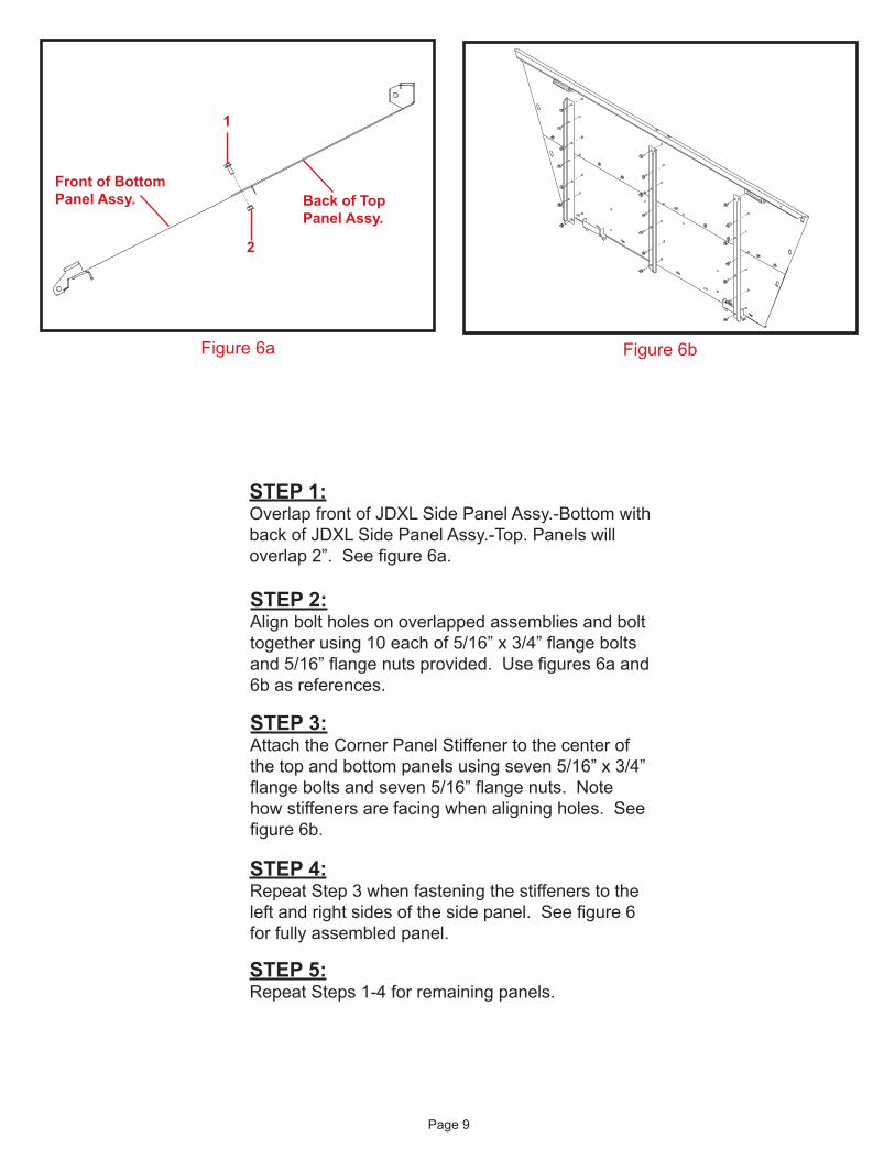
STEP 1:Overlap front of JDXL Side Panel Assy.-Bottom with back of JDXL Side Panel Assy.-Top. Panels will overlap 2”. See figure 6a.
STEP 2:Align bolt holes on overlapped assemblies and bolt together using 10 each of 5/16” x 3/4” flange bolts and 5/16” flange nuts provided. Use figures 6a and 6b as references.
Figure 6a Figure 6b
Front of Bottom Panel Assy. Back of Top
Panel Assy.
1
2
STEP 3:Attach the Corner Panel Stiffener to the center of the top and bottom panels using seven 5/16” x 3/4” flange bolts and seven 5/16” flange nuts. Note how stiffeners are facing when aligning holes. See figure 6b.
STEP 4:Repeat Step 3 when fastening the stiffeners to the left and right sides of the side panel. See figure 6 for fully assembled panel.
STEP 5:Repeat Steps 1-4 for remaining panels.

Page 10
STEP 2:Assemble all four corner panels to the frame (panels with windows are to be fastened to the front) and slowly fold the panels outward to accept the front, rear, and side panels. See figure 8.
FRAME ASSEMBLY
Arrange the frame components as shown in figure 7. The frame corner with the serial number decal is the left front frame corner. Fasten the frame joints together with two 5/16” x 3/4” flange bolts and two 5/16” serrated flange nuts per joint. See figure 7a.
STEP 1:Using one 3/8” x 6” hex bolt, two 3/8” washers and one 3/8” nylon lock nut per hinge point, attach the extension corner panels to the frame of the grain tank extension. See figure 8.
PANEL ASSEMBLY
Figure 7
Figure 7a
NOTE: DO NOT over tighten nuts and distort hinge component, but ensure nylon lock nut fully engages bolt threads.
REAR
FRONT
26
26
26
26
29
2928
RIGHT
LEFT
28

Page 11
Figure 8
STEP 3:Assemble the front, rear, and side panels the same as the corner panels. Please ensure that the panel with DANGER decal is the rear panel. This panel will also receive the safety step.
STEP 4:Remove the partial cut slugs in the center of the rear panel, and fasten the safety step to the rear panel using 5/16” x 3/4” flange bolts and 5/16” serrated flange nuts. When mounting, place the nuts to the inside. See figure 8a.
Figure 8a
REAR PANEL
FRONT
REAR
LEFT
RIGHT
ATTENTION: DANGER decal must be facing the rear of the combine!
ATTENTION: DAMAGE TO CORNER PANEL CAN OCCUR IF NOT FOLDED OUTWARD SLOWLY!

Page 12
STEP 5:Fasten the M60 additional sensor brackets to the bottom of right & left side panels using two 1/4” x 1” hex bolts, two 1/4”-20 center lock nuts, and four 1/4” flat washers. Factory sensor will attach to this bracket with original sensor bracket and harware. See figures 9 and 9a.
STEP 6:Fasten the tank full sensor brackets to the top of the left & right side panels using one 5/16” x 3/4” flange bolt, one 5/16” serrated flange nut, and one 5/16” flat washer. See figure 9.
STEP 8:Remove the partial cut slugs from the center of the vertical leg on the front panel, and mount the base GPS bracket using 5/16” x 3/4” flange bolts and 5/16” serrated flange nuts. See figure 11. (Maurer does not provide a wire harness extension for the GPS reciever.)
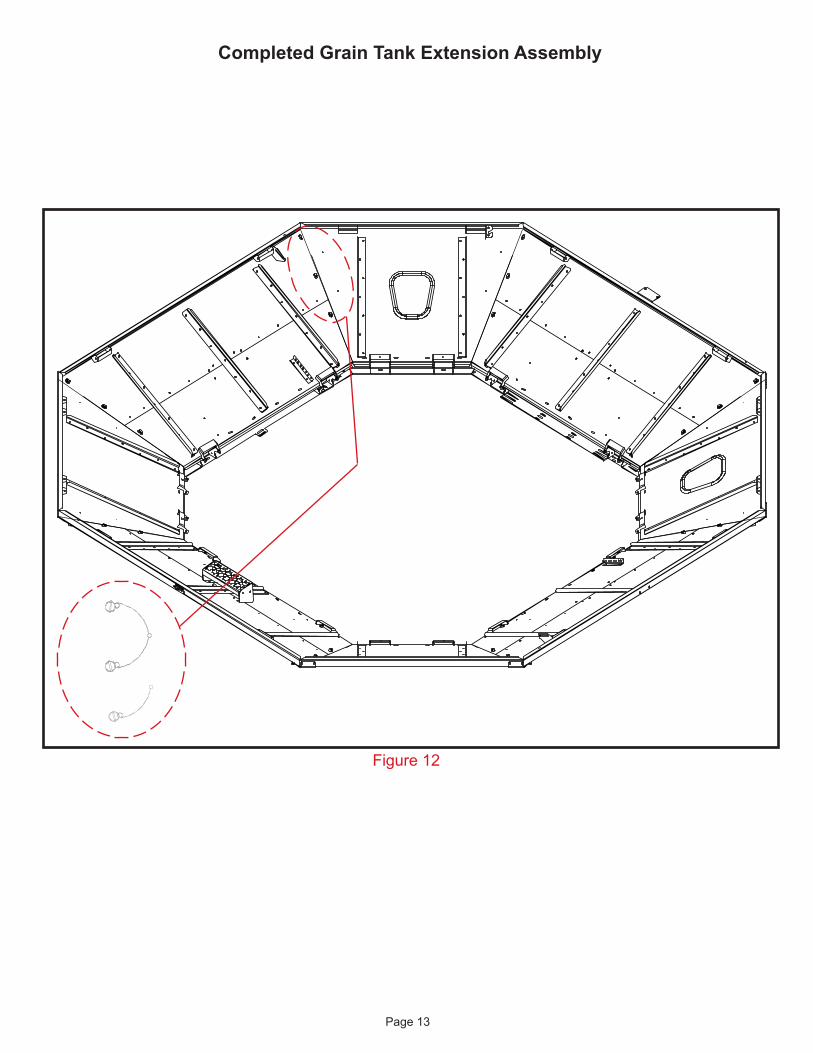
STEP 9:Align two nylon lanyards with one press rivet and fasten together. Loop and lock the ends of the lanyards around one lynch pin each. Fasten the complete assembly to the two small holes located on the corner panels. See figure 12.
STEP 7:Fasten the provided light bracket to the left front corner using one 5/16” x 3/4” flange bolt, one 5/16” serrated flange nut, and one 5/16” flat washer. See figure 10.
Figure 9 Figure 9a
M60 MID-LEvEL BIN SENSOR BRACKET
BIN FULL SENSOR BRACKET
Figure 11Figure 10
Page 13
Figure 12
Completed Grain Tank Extension Assembly

Page 14
REMOvAL OF jOHN DEERE FACTORY BIN EXTENSIONS
1) This bin extension is designed to fit the John Deere S680 and S690 combines. 2) The factory JD (Manual Fold and Auto Fold) bin extensions must be removed from the combine before installing the Maurer bin extension.3) Use care when dismantling the JD extension as later in these instructions you will be required to utilize existing JD sensor & brackets, tank light, wiring, and some fastners.4) If your combine came equipped with the Auto folding extension, we recomend removing all panels, panel hinges, and nylon corners.5) We also suggest removing the horizontal and vertical linkage arms (See figure A), (Except for the vertical arm that is attached to the clean grain auger.) that connect the panels to the rotating shafts in side of the grain tank.6) The rotation shafts and all linkages used to fold the clean grain auger must remain funtional. This will allow factory installed safety features to fuction properly. See figure B.7)When transporting combine on road ways the clean grain auger MUST be folded down in order to allow the combine to reach maximum ground speed. The folding functionality of the clean grain auger will still be operable by using the JD bin extension menus and icons on the operator’s side console screen in the cab of the combine.
Figure BFigure A

Page 15
REF.# PART # qTY. DESCRIPTION
1. 1AFC08E0000 18 5/16” Serrated Flange Nut 2. 1AFC37E00L0 2 5/16” x 3/4” Flange Bolt 3. 1AFC37EAAD5 16 5/16” x 1-1/4” Flange Bolt 4. R3E000234P0 2 Frame Spacer - JDXL Ext. 5. R3E000235P0 2 Mounting Plate - JDXL Ext. 6. R3E000241P0 1 JDXL Left Mount Bracket
mounting Plates and Frame spacersincluded in the maurer s-series (9E000032)
bin Extension for the s660, s670, s680, s690 sTs combines
Figure 13
FRONT
REAR
PARTS LIST
Please order replacement parts by PART NO. and DESCRIPTION.
5
LEFT SIDE
RIGHT SIDE
4
3
1
1
3
3
3
3
11
1
5
1
3
3
3
3
11
1
2
1
6
Page 16
LEFT SIDE
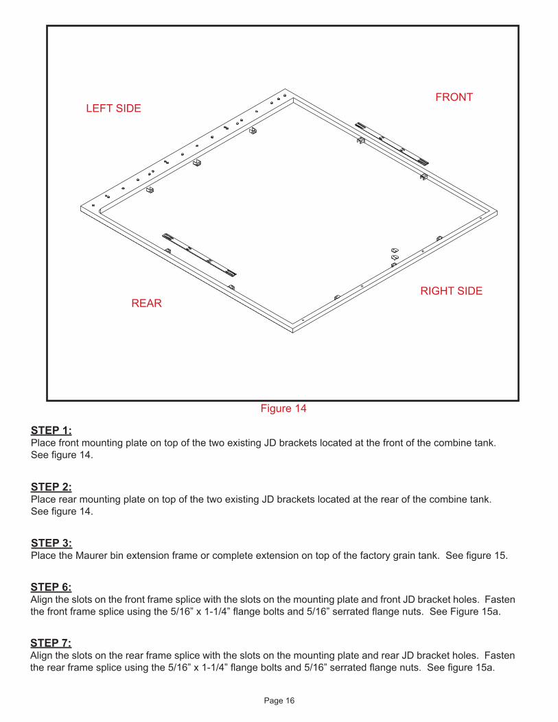
Figure 14
STEP 2:Place rear mounting plate on top of the two existing JD brackets located at the rear of the combine tank. See figure 14.
REAR
LEFT SIDE
STEP 3:Place the Maurer bin extension frame or complete extension on top of the factory grain tank. See figure 15.
STEP 1:Place front mounting plate on top of the two existing JD brackets located at the front of the combine tank. See figure 14.
RIGHT SIDE
FRONT
STEP 7:Align the slots on the rear frame splice with the slots on the mounting plate and rear JD bracket holes. Fasten the rear frame splice using the 5/16” x 1-1/4” flange bolts and 5/16” serrated flange nuts. See figure 15a.
STEP 6:Align the slots on the front frame splice with the slots on the mounting plate and front JD bracket holes. Fasten the front frame splice using the 5/16” x 1-1/4” flange bolts and 5/16” serrated flange nuts. See Figure 15a.

Page 17
Figure 15Figure 15a
REAR
FRONT
RIGHT SIDE
LEFT SIDE
FRONT
Figure 15b
STEP 8:On the right side of the combine tank, postion the frame spacers on the center existing JD bracket. See figure 15.
STEP 9:Align the slots on the right frame splice with holes on the frame spacers and the JD bracket. Fasten right frame splice with 5/16” x 1-1/4” flange bolts, and 5/16” serrated flange nuts. See Figure 15b.
STEP 10:On the left frame splice remove the two slot knock-outs. Remove two factory bolts from the grain tank located directly below the knock-outs. See figure 15.
STEP 11:Place the left mount bracket flush against the tank frame and extension frame. Align horizontal slots with the bolt holes on the tank and align the vertical slots with the knock-out slots on the frame splice.
STEP 12:Use the factory bolts removed earlier to bolt bracket to tank and use 5/16 x 3/4” flange bolts and 5/16” flange nuts to bolt bracket to extension frame. See figure 15.

Page 18
INSTALLATION OF TANK CAPS
Please order replacement parts by PART NO. and DESCRIPTION.
PARTS LIST
Front
Rear
3
3
3
3
LeftRight
Figure 16
REF.# PART # qTY. DESCRIPTION
1. 1AFC37E00L0 8 5/16” x 3/4” Flange Bolt 2. 1AFC08E0000 8 5/16” Serrated Flange Nut 3. R3E000218PO 4 Tank Cap - JDXL Ext.

Page 19
Figure 17
1
2
STEP 1:Layout the Tank Caps according to figure 16.
STEP 2:Fasten Tank Caps and Spacers to the extension frame corners using 5/16”x 3/4” bolts and 5/16” serrated flange nuts. (Tabs will be on the underside of the frame) See figure 17.
STEP 3:Complete by screwing the Tank Caps to the outer rim of the tank with #12 x 1” self tapping screws.
SENSOR AND LIGHT WIRING
STEP 1:Mount the OEM light to the previously mounted light bracket on the left front corner. Fasten with the original hardware. Clip and extend the wiringfor the grain tank light, including ground wire. (Maurer does not provide a wire harness extension for the grain tank light.)
STEP 2:Mount the tank full sensor to the slot in the sensor bracket located on the right front corner using the original hardware. Use the provided wire harness to connect the sensor to the OEM wiring.
NOTE: DO NOT secure right rear tank cap with self tapping screws until the Corner Fill Angle (page 20) has been mounted.

Page 20
STEP 1:Locate the right rear corner of your Maurer Bin Extension. Identify the gap located under the tank cap in that corner. See figure 19.
Please order replacement parts by PART NO. and DESCRIPTION.
Corner Fill Angle installation instructions
PARTS LIST
STEP 2:From inside the tank use the filler angle to cover the gap with the non-slotted leg flush with the corner tube of the combine tank. The slotted leg should be pointed to the inside of the tank.
STEP 3:Remove slot knock-outs on the tank cap and use the 5/16” x 3/4” flange bolts and 5/16” flange nuts provided to mount the filler angle to the tank cap. See figure 20.
2
1
3
right reartank cap
Figure 18
REF.# PART # qTY. DESCRIPTION
1. 1AFC08E0000 2 5/16” Serrated Flange nut 2. 1AFC37E00L0 2 5/16” x 3/4” Flange Bolt 3. R3E000215PO 1 RR Corner Fill Angle

Page 21
right rearcorner panel
tank cap
gap
Figure 19
tank cap
filler angle
Figure 20
Outside of combine tank
Inside of combine tank
Page 22
REF.# PART # qTY. DESCRIPTION
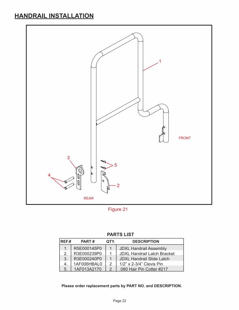
1. R5E000145P0 1 JDXL Handrail Assembly 2. R3E000239P0 1 JDXL Handrail Latch Bracket 3. R3E000240P0 1 JDXL Handrail Slide Latch 4. 1AF006HBAL0 2 1/2” x 2-3/4” Clevis Pin 5. 1AF013A2170 2 .080 Hair Pin Cotter #217
HANDRAIL INSTALLATION
Figure 21
1
2
4
FRONT
REAR
PARTS LIST
Please order replacement parts by PART NO. and DESCRIPTION.
35

Page 23
STEP 1:Remove the two cotter pins and 1/2” pins that fasten the factory handrail to the combine. The factory handrail will no longer be used. STEP 2:Slide the Maurer handrail inside the factory Deere mounting brackets.
FAILURE TO REPLACE HANDRAIL COULD RESULT
IN SERIOUS INJURY OR DEATH
WARNING
Figure 22
Figure 23
Figure 24
Front Mount
Factory Pin
Maurer Handrail
STEP 3:Using the bottom hole at the front, attach the handrail to the factory mounting bracket with the 1/2” pin you removed in STEP 1. See figure 22. Latch BracketSTEP 4:With the Maurer handrail inside the rear factory Deere bracket, place the latch bracket between the handrail and the factory Deere bracket. See figure 23.
Slide Latch
STEP 5:Line up the lower hole on the latch bracket with the bottom hole on the handrail. The arc slot on the latch bracket will line up with top hole on the handrail.
STEP 6:Place the slide latch against the outside of the factory Deere mount with the bent tab toward the outside of the handrail.
STEP 7:Align the slots on the slide latch with the holes on the factory Deere mount, latch bracket, and handrail. See figure 24.
STEP 8:Secure the slide latch, latch bracket, and handrail to the factory Deere mount using the 1/2” x 2-3/4” clevis pins and cotter pins provided. See figure 24.

6/27/12