com - electrical part manual s cm circuit breaker description 1 three pole high strength glass...
TRANSCRIPT

molded case circuit breakers 1250 -3000A
mastering electrical power
MERLIN GERIN www . El
ectric
alPar
tMan
uals
. com

Compact CM circuit breaker table of contents
MERLIN GERIN
molde d case c i r cu i t b r e ake r
introduction standard compliance performance other performances ratings interrupting capability
advantages description
trip unit characteristics ST 206D ST 3068 - 8T 31 68 neutral sensor portable test kit test procedure
time current curves 8T 2060 (overcurrent protection) 8T 3068 - 8T 3068T - 8T 3168T (overcurrent protection) 8T 3068T (ground fault protection) 8T 31 68T (ground fault protection)
accessories terminals location shunt trip undervoltage trip device auxiliary and alarm switches overcurrent trip switch motor operator OFF position locking
wiring diagrams
molde d case switch construction ratings accessories- dimensions- installation
dime nsions
appe ndix
routine and maintenance guidelines UL 489 test procedures application of 1 00 % rated breakers international standards
page
2 2 2 2 2 2
2 3
4 5 6 6 6
7 8 9
10
1 1 1 1 1 2 1 2 1 2 12 1 3 13
14
15
1 5 1 5 1 5
16
20 22 23 24
www . El
ectric
alPar
tMan
uals
. com

Compact CM circuit breaker introduction, advantages
standard compliance CM breakers are built in accordance with Underwriters Laboratories standard U L 489. The circuit breaker and its accessories, except when noted, are listed under UL File E1 07820.
performance C M breakers are designed to meet or exceed UL 489 requirements. Standard tests : UL 489 standard section 1 2 to 25 give test values for calibration, overload, temperature, endurance, interrupting ability, dielectric. On pages 20 of this document, extracts of UL standards are given. Additional tests : CM breakers meet UL 489 standard additional requirements : • high available fault current • 100% rating as shown in the page 2 1
other performances The U L 489 standard assures that the circuit breaker has sufficient characteristics to be used in normal conditions. However, CM circuit breakers exceed the standard requirements without additional cost : in endurance : the heavy duty mechanism and contact design provides a mechanical endurance of 1 0,000 operations and an electrical endurance of 2 ,000 cycles in accuracy : the solid state trip unit provides a more accurate protection than required by the standard, see time current curves page 7
small dimensions A unique and small insulating casing for all five ratings ( 1 250 to 3000A) simplifies layout design and installation.
reverse feeding
maintenance free breaker design reduces downtime and maintenance costs.
high endurances The endurance of the design is four times greater than that required by the standards.
isolation function The operating handle is representative of the position of the main contacts. The OFF position can be reached only when the main contacts are fully opened.
2
interrupting ratings CM type 3-pole
ampere ratings current sensors (A)
standard rated breaker
CM 1 250 HE 1 250 CM 1 600 HE 1 600 CM 2000 HE 2000 CM 2500 HE 2500 CM 3000 HE 3000
1 00% rated breaker
CM 1 250 HH 1 250 CM 1 600 HH 1 600 CM 2000 HH 2000 CM 2500 HH 2500 CM 3000 HH 3000
ratings Five continuous current ratings : 1 250, 1 600, 2000, 2500 and 3000A. Two types are listed : • standard rated circuitbreakers • 100% rated circuit breakers :may be used for continuous operation at 1 00% of its rating as permitted by 1 984 National Electrical Code, paragraph 21 0-22(c) exception no 2 and 220 - 2 1 0 (b) exception, when used in an enclosure described in page 16, 1 7 and 1 8 with size and ventilation.
built-in control terminal blocks Are provided with the accessories, consequently intermediate terminals are not required for the connection of control wiring.
UL listed interrupting ratings RMS Symmetrical. Amps 240V 480V
1 25,000 85,000 1 25,000 85, 000 1 25,000 85, 000 1 25, 000 85, 000 1 25,000 85, 000
1 25 000 85 000 1 25,000 85, 000 1 25,000 85,000 1 25,000 85,000 1 25,000 85, 000
600V
50,000 50,000 50,000 50,000 50,000
50 000 50,000 50,000 50,000 50, 000
MERLIN GERIN
......
www . El
ectric
alPar
tMan
uals
. com

Compact CM circuit breaker description
1 three pole high strength glass polyester casing 2 auxiliary and alarm switches 3 undervoltage trip device 4 shunt trip
5 motor operator 6 ON-OFF indicator directly operated by the mechanism (optional with auxiliary switches) 7 provisions for padlock, when contacts are actually opened 8 handle extension 9 push to trip button 10 handle with three positions: ON- TRI PPED-OFF 1 1 solid state trip unit 12 overcurrent trip switch terminal block 13 neutral sensor terminal block
MERLIN GER IN
2 3
6
3 www . El
ectric
alPar
tMan
uals
. com
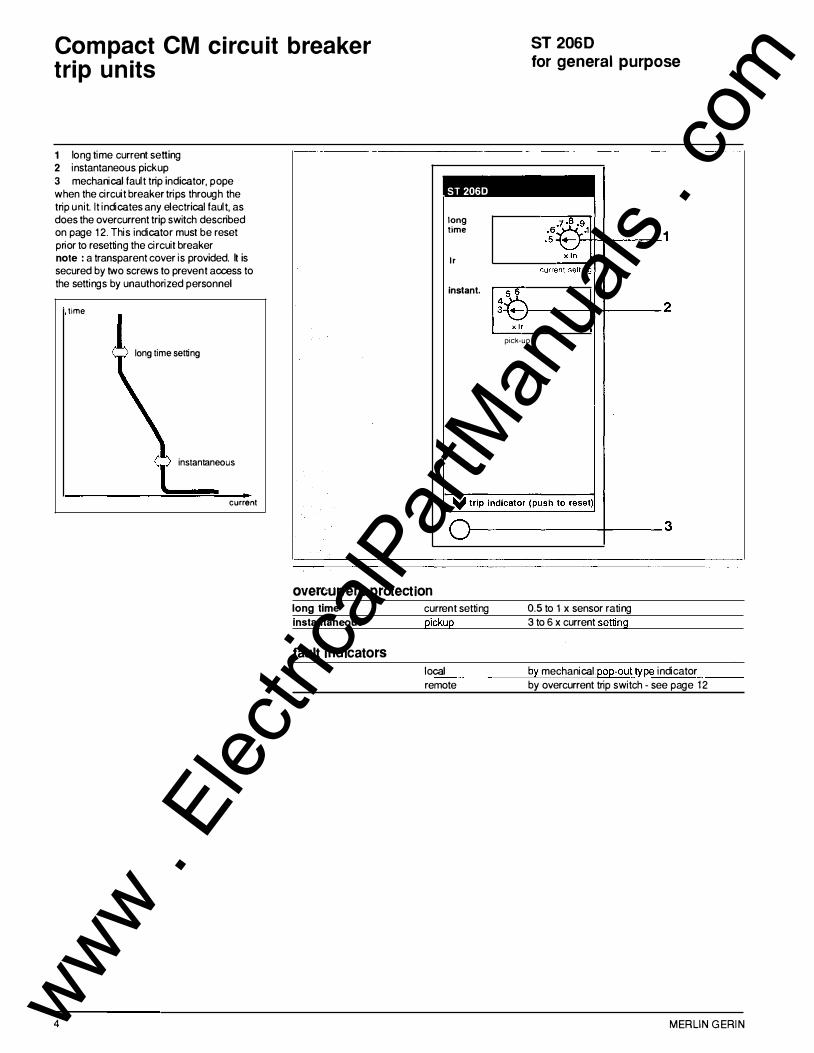
Compact CM circuit breaker trip units
1 long time current setting 2 instantaneous pickup 3 mechanical fault trip indicator, pope when the circuit breaker trips through the trip unit. It indicates any electrical fault, as does the overcurrent trip switch described on page 1 2. This indicator must be reset prior to resetting the circuit breaker note : a transparent cover is provided. It is secured by two screws to prevent access to the settings by unauthorized personnel
time
long time setting
instantaneous
current
ST 2060
long time
lr
instant.
ST 2060 for general purpose
r-------�-------2
pick-up
r-------------�-----3
overcurren t protect i on long time curren t setting 0.5 to 1 x sensor rating instantaneous pickup 3 to 6 x current setting
f aul t i nd i c a tors local by mechanical. pop-out type indicator remote by overcurrent trip switch - see page 12
4 MERL IN GERI N www . El
ectric
alPar
tMan
uals
. com

Compact CM circuit breaker trip units
ST 306S - ST 316S for selective application and ground fault protection
1 long time current setting 2 short time pickup and delay 3 ground fault pickup and delay 4 mechanical fault trip indicator, pope when the circuit breaker trips through the trip unit. It indicates any electrical fault, as does the overcurrent trip switch described on page 12 This indicator must be reset prior to resetting the circuit breaker 5 test receptacle for use with portable test kit cat. no. 55764 note : a transparent cover is provided. It is secured by two screws to prevent access to the settings by unauthorized personnel
time
'---------------�rent I time
current
CD The short tirm delay may be set at zero if instan taneous tripping is required
@ The maximum ground fault pickup of ST 316ST rmets 1984 National Electrica Code paragraph 230-95 (a) (not
to exceed 1200A)
CJJ Used on CM 1250- CM 1600 and CM 2000
@) Used on CM 2500 and CM 3000
MERLIN GERIN
ST 306ST
long time 1 lr
current setting
short 6
� time :G .1 2 0-
xlr pick-up delay
ground e .ie fault .3 3 2 .1-
xln p1ck-up delay
test
ooeoooooeo 4
�--------------�-------5
overcurrent protection long tim e short tim e
instantaneous test receptacle
current setting 0.5 to 1 x sensor rating pickup 2 to 8 x current setting delay 0- 0.1 - 0.2- 0.3 CD pickup override at 35,000A for overcurrent and ground fault testing
ground fault protect i on ®
(option T) pickup
delay
faul t i nd i c a tors local remote
ST 306ST cr> : 0.2 to 0.5 x sensor rating ST 316ST@) : 0.2 to 0.4 x sensor rating 0.1 - 0.2- 0.3- 0.4
by mechanical pop-out type indicator by overcurrent trip switch - see page 12
5 www . El
ectric
alPar
tMan
uals
. com

Compact CM circuit breaker trip unitneutral sensor
neutral sensor Ground fault protection may be applied on 304W or 303W circuits. On 304W an external neutral sensor must be used. This neutral current sensor shall have the same ampere rating as the breaker. The following are current sensors for use with CM breakers equipped with ST 306ST or ST 316ST trip units.
rating
1 250A 1 600A 2000A 2500A 3000A
wirin g
for
CM 1 250 CM 1600 CM2000 CM2500 CM3000
cat. no.
55760 55759 55758 55757 55756
It shall be as indicated in opposite fig. and on the neutral sensor label . Observe control wiring (terminal S 1 -S2, T 1 -T2). termi nals
location
� N neutral
� -
main breaker
_.... -
_....
�
T1 )-<� S1
�II I
I ground fault neutral CT's
• terminals S 1 -S2 (neutral sensor) are of "quick-connect" type ( 1 /4" female tab socket are supplied with current sensors) .
note : ground terminal T 2 o r S2
neutral sensor portable test kit
S1.,..T1
- ;. i>) i) S�T2
I I ) feeder
breaker
• terminals T1 -T2 (circuit breaker) are pressure type terminal blocks. These terminals are intended for use with 1 8 to 1 4 AWG stranded copper wire.
caution :in 304W systems, do not connect or do not short terminals Tt and T2
portable test kit All tests performed by the test kit are functional tests only designed to electrically test the operating integrity of the trip unit, the flux transfer shunt trip and the mechanical operation of the breaker. Tests are not designed as a check of the breaker calibration. Calibration tests can best be done at the factory.
Complete test operating instructions and required setting details are given on the side of the test kit. For convenience, the operating instructions are repeated below.
ST 306S and ST 31 6ST trip units are equipped with test points that can be used with the portable test kit. This test kit allows independent tests on the three following protections : • long time • short time • ground fault on ST 306ST and ST 31 6ST
The portable test kit should be supplied by a 1 20V 60Hz source.
Catalog number 55764
6
test procedure Prior to testing 1 Operate on "OFF load" conditions. 2 Set control voltage selector located at the back of test kit to proper voltage. 3 Switches for "control power" and "long time" test have to be in the OFF position. 4 Remove the transparent trip unit cover and insert test plug in receptacle. 5 Plug in the power cord. 6 Turn "control power" switch ON. The "power on" lamp should light. If not, check the source, then the test kit fuse (0.5 A fuse). 7 Close breaker. 8 A period of 20 seconds should be allowed between tests.
Testing . 9 short time : press short t1me test push button for one second to trip the breaker. ground fault : press ground fault push button for one second to trip the breaker. long time : • set current selector of test kit to match current setting of the breaker trip unit • move the "long time test" switch to ON. The breaker will trip between 50 and 200 seconds. cauti on: when the breaker trips, return the "long time test" switch to OFF posi tion immediately. Under no circumstances should thi s switch be i n the ON posi tion for more tha n 4 minutes
Return to normal service 10 Return "control power"switch to OFF and unplug power cord from supply. 11 Remove test plug from trip unit and replace trip unit transparent cover.
warni ng : Touchi ng test plus pins may cause electrical shock when power cord is plugged and power switch in ON position. The control power switch should never be on the ON positi on unless test plug is connected.
MERLIN G ERIN www . El
ectric
alPar
tMan
uals
. com
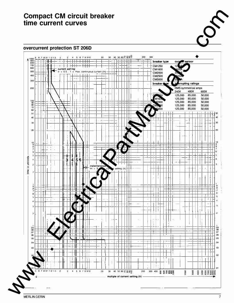
Compact CM circuit breaker time current curves
overcurrent protection ST 2060
1000 5 6 7 8 9 1 1 2 1 5 4 5 6 7 B 910 20 30 40 50 60� ��� 200 300
900 BOO 700 600 500
400
300
200
100 90 80 70 60 50 40
30
20
10 9 B
1 9 B 7 6
1 09 08 07 06 05
04
03
02
01
1-1-
-
t-
1-t-- -
I I I current setti��:
1 1 1 1 1
f"''lll- lr = 0.5 ... 1 x max. continuous current (In)
'\� -+ --I I I
'\ '\ \c ' '
\ -\· i -�---�
1\ I � 1\
3 4 56 I -I instantaneous:
I
--·
I lm = 3.. 6 x current setting (lr)
+-�-i
----- · -
--
I --
-- -- -+ j
! I I I i ,_ ·�-
I i I ; I I I
: H-
�-·
i -r-� 1- I
! --
· +- I I I
j I i
breaker type
CM1250 CM1600 CM2000 CM2500 CM3000
breaker type
t-- CM1250 CM1600 CM2000 CM2500 CM3000
� ' �+ f-t -- -
·-- -t-- - ,-
I ---r-- 1 I
, .
-----
t
1--�-' I �
�--:- .--t
' !
I I
I
1 i .5 6 .7 .8 .9 1 1.2 1.5 4 5 6 7 B 910 20 30 40 so 60 R ��g 2oo 300 400
-
current sensor
1250A 1600A 2000A 2500A 3000A
interrupting ratings
RMS symmetrical amps
240V 480V
125,000 85,000 125,000 85,000 125,000 85,000 125,000 85,000 125,000 85,000
-
I
j -
-- t--
I
- +- -
-I-I-
I '
·--
j i
I
I I i I
600V 50,000 50,000 50,000 50,000 50,000
t-
i
50
40
30
20
10 9 B 7
1 9 B
1 09 08 07 06 05
04
03
02
01 0 8 0 0 000 g g g g ggg v .. , <0 ,..._ com�
multiple of current setting (lr) ___________________ _,..
MERLIN GERIN 7 www . El
ectric
alPar
tMan
uals
. com

Compact CM circuit breaker time current curves
overcurrent protection ST 306S - ST 306ST - ST 316ST
8
1000 5 6 7 8 91 1 2 1 5 4 5 6 7 B 910 20 30 40 50 60g g�§ 900 BOO 700
current setting: l�tr = 0.5 ... 1 x max. continuous current (In)
f-+--1- '
\' � 1\ \
\
1\ ·- 1-
t- - 1\
I-f-- l\ I' 1--
' � t-t- t f-- 1\ 1\
I-I-
r-- 2 -- 4 - 6 8 jlf== short-time pickup: lm = 2 ... 8 x current setting (lr)
I-I-
-I-.3
r: .2 - I
I
. 1
0 I
.5 .6 .7 .8.91 1.2 1 .5 4 5 6 7 8 910 20 30 40 sosog��� .--------- multiple of current setting (lr) --------;�
3
breaker type current sensor
CM1250 1250A CM1600 1600A CM2000 2000A CM2500 2500A CM3000 3000A
breaker type Interrupting ratings
RMS symmetrical amps 240V 480V 600V
CM1250 125,000 85,000 50,000 CM1600 125,000 85,000 50,000 CM2000 125,000 85,000 50,000 CM2500 125,000 85,000 50,000 CM3000 125,000 85,000 50,000
note: ground fauh protection - with ST 306ST see curve p. 9
- with ST 316ST see curve p.t 0
-f--t-
.3 --
.2 instantaneous
35,�0� .1
0
3 4 5 6 7 8 910 20 30 40 50 60 � :il�8 •------- amperes x 1000
20
10 9 B
1 9 B 7 6 5
3
1 09 08 07 06 05
04
03
02
01
MERLIN GERIN www . El
ectric
alPar
tMan
uals
. com

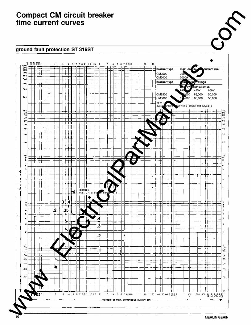
Compact CM circuit breaker time current curves
ground fault protection ST 306ST
1000'8 8 � ��� .4 .5 .6 .7 .8.9 1 1.2 1.5 2 3 4 5 6 7 8 910 900 800 700 600
1-· r-r-
f--
--
-+-
c--
-r-
t-' ·t -f-'
--r--
I
-
- -
.2 -
'
-
I --
I
I 1--
I .2
'-t--I
-
pickup:
I
-
I
- .
r-� 0.2 ... 0.5 x current sensor (CT) .3 .4 .5
.4 ---- f--.3
.2 I
.1 I '
I I
i .3 .4 .5 . 6 .7 .8.9 1 1.2 1.5 2
I
I
I 4 5 6 7 8 910
20
I
-----'--·-
20
30
breaker type max. continuous current (In)
CM1250 1250A CM1600 1600A CM2000 2000A
breaker type interrupting ratings
RMS symmetrical amps 240V 480V 600V
CM1250 125,000 85,000 50,000 CM1600 125,000 85,000 50,000 CM2000 125,000 85,000 50,000
note: overcurrent protection with ST 306ST see curve p. 8
t
1--· - !
1--r-
i i I ' I
I I I
I • --
I I
I , -
I I
80 70 60 50
40
30
20
10 9 8
1 9 8 7 6
1 09 08 07 06 05
04
03
02
01 30 40 50 soRg�g. 200 3oo 400 � � R §g�
._ __________________ multiple of max. continuous current (In) -------------------•
MERLIN GERIN 9 www . El
ectric
alPar
tMan
uals
. com
Compact CM circuit breaker time current curves
ground fault protection ST 316ST
:g � :; �� .... 1000 900 BOO 7 00
4 5 6 7 8 9112 15 2 4 5 6 7 8 910 20 30
10
f--+- -
f-f-
f-
1-
I -
I-I-
I-t-
-f---
-I-
-f-
I-e-.-
T t-- -
I---- - t-- - t-
·---1----- -
t-
j I I
i
�
.3 .4 .2 t:35
-
} i I
I I I
I I I I
f- -f-
f- -- f- +---
I
f- +--t- H--j--- f-- - f- 't-
+-- t-- It I I f-f-- t-t- rrt-
I- f--f- f- I-pickup:
I- 0.2 ... 0.4 x current sensor (CT) I-
- -
I
.4
.3
.2 I
.1
I I i
i I I
+--i I
1--- �
I
1------l -1---t-1---i t---
t--H _I
- t-
r-+ - t-
f- I - 1 --=t __j_
---t -- --
I I
i
I I I
'---+
I
breaker type max. continuous current (In)
CM2500 2500A CM3000 3000A
breaker type interrupting ratings
RMS symmetrical amps 240V 480V 600V
CM2500 125,000 85,000 50,000 1 CM3000 125,000 85,000 50,000
overcurren1 protection wnh ST 316ST see curve p. 8 Hnote: --
i
I I
f--;-f- f-
I _L_ - � I I
---;-----t-
-j--
I L_t- r l j
f-J_ t --j-- - t--
---t-
t
-H f-t-- \-- -t-I
I I I
I
IT: ---L f-+- -- �
- --- 1- -- 1 j--I I 1-I I -·
I I I
_l I
i :
f-
+---
--
-- -
'
I
I
100 90 80 70 60 50
40
30
20
10 9 B 7 6
1 9 8
1 09 08 07 06 05
04
03
02
01 .2 .3 .4 .5 .6 .7 .8.9 1 1.2 1.5 2 4 5 6 7 8 910 20 30 40 so eoR�gg 200 300 400 g 8 888§
Ln cor---com ....
4------------------- multiple of max. continuous current (In) ------------------.
MERLIN GERIN www . El
ectric
alPar
tMan
uals
. com

Compact CM circuit breaker accessories
Internal accessories are field installable and comply with requirements of Underwriters Laboratories Standard UL 489 and are l isted for field installation per UL E 1 07821 .
terminals All internal accessories are equipped with pressure type terminals located on the side of the breaker. Each terminal may be connected by one or two copper wires 18 to 1 4AWG. The terminals comply with Underwriters Laboratories Standard UL486A. Tightening torque : 1 2 1b.in.
MERLIN GERIN
loc a t ion
• •
terminals
:�:. ::::�� ) aux. switch or aux. switch
alarm switch
shunt trip } or
•
- or aux. switch
- -
aux. switch} 1-,
uOOervottage trip
1 1 www . El
ectric
alPar
tMan
uals
. com

Compact CM circuit breaker accessories
shunt trip undervoltage trip device auxiliary and alarm switches overcurrent trip switch
shunt trip The shunt trip is intermitently rated with a series normally open contact. AC shunt trips can be operated at 55 percent of their rated voltage, making them suitable for use with ground fault protection devices. minimum operating voltage : AC : 55 % of rated voltage DC : 75 % of rated voltage
undervoltage trip device Undervoltage trip devices may be used as circuit interlocks. If an undervoltage condition exists, operation of the closing mechanism of the circuit breaker will not permit the main contacts to touch, even momentarily. dropout : 35-70 % of rated voltage pickup : 85 % of rated voltage note : to prevent the breaker from tripping in the event of transient voltage drops, an external time delay may be added (fixed delay : min. 0.5 sec. - max. 1 sec., voltage : 1 20V AC, not UL listed)
auxiliary and alarm switches Auxiliary switches consist of SPOT switches and provide remote information of the breaker status. Alarm switch provides alarm/lockout information. When the breaker is reset, the "a" contact (alarm) is open, and the "b" contact (lockout) is closed. This SPOT switch is operated when the breaker is tripped by the trip unit, shunt trip or undervoltage trip device or "push-to-trip" button.
without mo tor operator 2 auxiliary switches cat. no. 55755 4 aux. + 1 alarm switch cat. no. 55754 for motor operator 4 auxi liary switches CD cat. no. 55676
CD not UL listed
overcurrent trip switch Supplied as standard with the trip unit. Operates in the same way as the mechanical trip indicator. The "a" contact closes when the breaker operates through the trip unit (overcurrent or ground fault). I t does not operate if tripping is by shunt trip, undervoltage trip device or push-to-trip button.
1 2
control voltage
_ __,_ __ I II- trip
rf I=
L.._ � IC1 I
_.._ __
control voltage
-- �--' � trip
I�:-v
'--� 1o1 I
_ __._ __
control voltage
rated inrush cal no. voltage (V) current (A)
60Hz 1 20 3.5 55740 240 1 .9 55741 480 1 55742 600 0.65 55743 DC 24 4.8 55744 48 1 .4 55745 1 25 0 .7 55746
rated seal-In cat. no. voltage (V) current (A)
60 Hz 1 20 0.5 55728 240 0.3 1n29 480 0. 1 5 55730
600 0 . 18 55731 DC 24 0. 14 55732
48 0.07 55733 1 25 0.02 55734
control voltage
---�lonfofffon _____ --...-....---------.,.......--¢"¢�
----------
��larm
P..r�R2¢.. 12 14 22 24 32 34 42 44 92 94
; b = �; � 'i> ;t =a b a b = F. ;b a ; � =a
21 31 111 121 131 141 191 I I I I I I I I I
----+- -+------__ ._ _ _. __ .._ _ _. _ __.. __
voltage (V) .. ..
2 auxiliary switches 4 auxi liary + 1 a larm switch auxiliary alarm auxiliary alarm
50/60 Hz 240 - 480 6 5 6 5 �60�
0��----
3�-- ----'--
3�-- ------�
3--------�
3-----------
DC �1 2�5'------�0�.5� ______ 0�-�5 �----�0�.5�------�0�.5�-------
250 0.25 0.25 0.25 0.25
control voltage
---.- -alarm
q4
voltage (V)
50/60 Hz DC
current (A)
240 2 1 25 0 . 1
MERLIN GERIN www . El
ectric
alPar
tMan
uals
. com

Compact CM circuit breaker accessories
motor operator The motor operator operates remotely the circuit breaker on orders from pushbuttons, switches or relays. Remote opening is performed by shunt trip or undervoltage trip device. It ensures resetting and closing in the same time. ON and OFF positions are clearly indicated by a flag indication : • white : ON • green : OFF Those two indicators are representative of the status of the main contacts :the OFF position can be indicated only when the main contacts are fully opened. Not UL listed.
<D caution : control diagram shall be designed to
interlock remote and OFF orders. CA-K auto-supply sw�ch/relay
M2 locking sw�ches
M3 auxiliary sw�ches (automatic resetting)
M4 alarm sw�ch
MERLIN GERIN
motor operator OFF position locking
rated voltage (V) cat. no.
control voltage
60Hz 1 20 55611 240 55613 277 55615 480 55617 DC 24 55618 48 55620 1 25 55624
operating voltage : 80-1 1 0% of rated voltage max. operation frequency : 2 per minute consumption :
• closing : 350VA • opening : refer to shunt trip or undervoltage trip device tables max. closing time : 1 .5 sec.
-------------------- �--�-
auxiliary switches cat. no. 55676
1 I
�---�� ,----" I 0 I I f I
I T : I I I I I I I 1A4 1s• 1c2
11 21 31 41 I A1 P2 I I I I I I I
_ ___________ J-----------L-
OFF position locking The breaker can be locked in the OFF position by the means of 1 to and/or 3 padlocks (padlocks not provided) and 1 Kirk key lock (KIRK or CASTELL key lock is provided -Factory mounted). note: • The adaptator accomodates up to 3 padlocks. Padlock shackle diameter: 1 /4 to 5/1 6 • keylock is of the captive key type, free when locked.
padlocking device cat. no. 55653 prov. for KIRK key lock<D cat. no. 55768 pmv. for CASTELL key lock<D cat. no. 55769
<D includes padlocking device
1 3 www . El
ectric
alPar
tMan
uals
. com
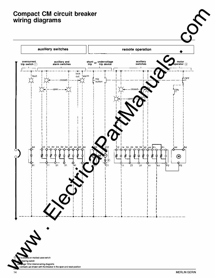
Compact CM circuit breaker wiring diagrams
�-------a_
u_
x_
i l_
i a_
r_y
__ sw __
i t_
c_h_e_s
________ �l �� ----------------r
_e_
m __
o_t e
__
o_
p_
e_
r_
a_
t i_
o_n
____________________ �
overcurrent trip switch G) auxiliary and
alarm switches shunt or undervoltage trip trip device
auxiliary switches
motor operator @
I I I ,.-------------'--------------, ,--------'---------, ,------------'----------, ,----'-------, --- ,--- r -- ------ --r- - -- 1 ---1 --- ---r- --- t-r- - - ---- --,- ,- - --- --------r---
l,ault : : � ��t lalarm �I 1 : I : I fl
)
� : M----closed-:---� g�ton T�-�-r-----��--------- OFF
I I I I I I I I I ,--v:--open--� 1 : i I �-closed--� �[S)N ! 1 I 1 I 1 �� r I I I I I *+ 1 I I 1 I I : --open-- I I I I I I I I I I I I I I I I
I I I I I I I I I
I I 12 14
I I I I I I I I I I I I I I I I I I I I : I I I I I I I I I 1 I 1 1 I I 1 : I I I I I I : I I I I I I I 1 I \ I I I 1 I I I I I I I I I I I I
I I : I I I I I 1 I I I I I I I I 1 I I I 1 I I I
u or sr ® ®
24 32 34 42 44 92 94 �4 �2 32 34 42 44 A4 B4
111 01 C1 111 l41 A1 P2 P2
I I I I I 1 I I I I I 1 I I 1 I I I I I I I I I I I I I I 1 I I 11 I I I I 1 I I I 1 I j I I ____ _. __ ______ __ ____ ...__ _ ----+--- �---_.._ ______ _ __. --�--------
CD nol available on molded case swrtch ® coil clearing swrtch @ see page 13 for internal wiring diagrams note : contacts are shown wrth the breaker in the open and reset posrtion
14 MERLIN GERIN www . El
ectric
alPar
tMan
uals
. com

Compact CM molded case switch
construction CM molded case switch is designed identically to CM molded case circuit breaker, except that it is not equipped with a trip unit. H igh instantaneous trip at 35,000 Amps. UL l isted under file E 107822.
Caution: molded case switches does not provide overcurrent protection. Molded case switch can be protected by a CM circuit breaker.
MERLIN GERIN
ratings m.c.s. ampere 600 V rating (A)
CM 1600 HA 1 600 at 240 V at 480 V at 600V
CM 2000HA 2000 at 240V at 480 V at600 V
CM 3000HA 3000 at 240V at 480V at 600V
accessories-dimensionsinstallation Molded case switch accessories, dimensions, installation and connection are identical to those of the corresponding circuit breaker (except for overcurrent trip switch).
page accessories 1 1 dimensions 16
short circuit withstand max. sym. Amps when protected by
1 25,000 CM 1 600 85,000 CM 1 600 50,000 CM 1600 1 25,000 CM 2000 85,000 CM 2000 50 ,000 CM 2000 1 25,000 CM 3000 85,000 CM 3000 50,000 CM 3000
15 www . El
ectric
alPar
tMan
uals
. com
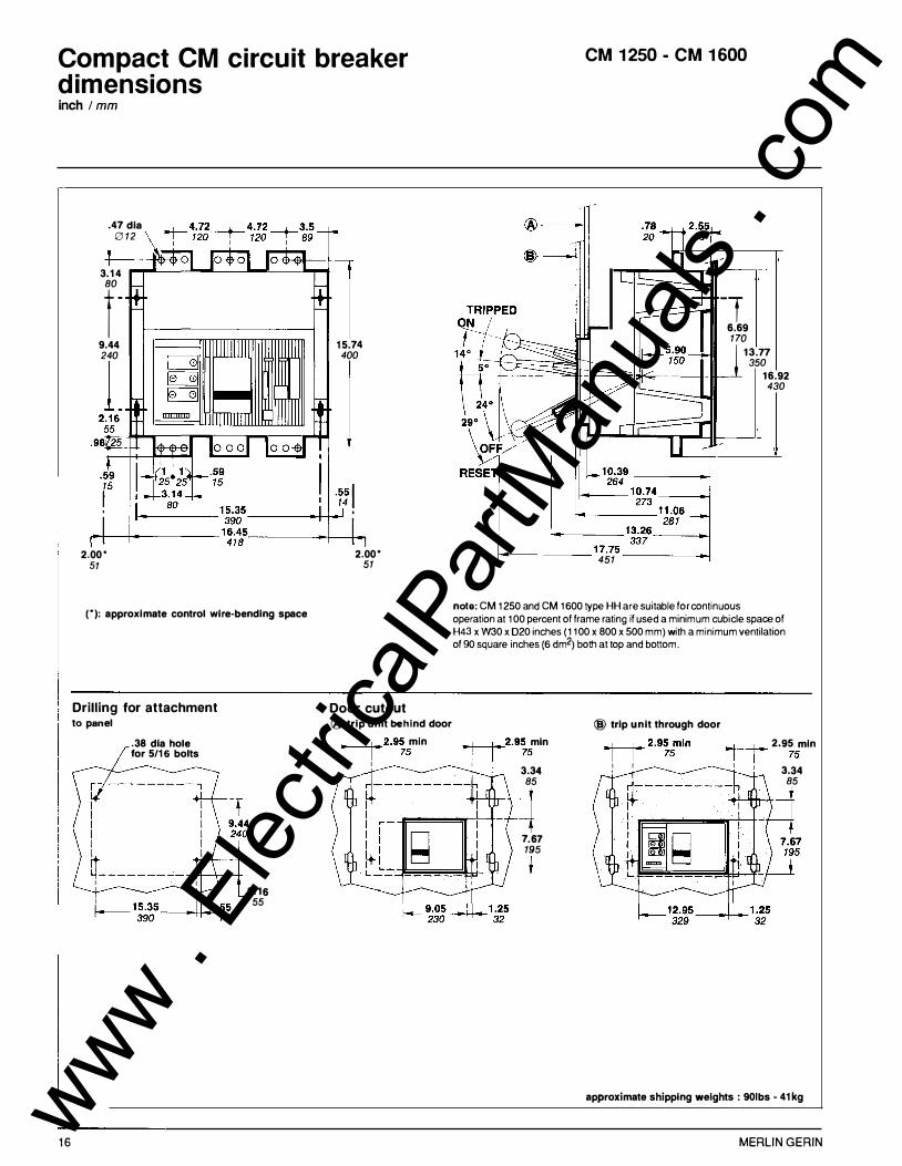
Compact CM circuit breaker dimensions inch 1 mm
.47 dia 012
3.14 80
r-9.44 240
L
2.00' 51
ITIIIIIIID
('): approximate control wire-bending space
16
Drilling for attachment to panel
.38 dia hole for 5/16 bolts
I I I I I I I I �----------� I I 2.16 55
l 15.74 400
J 2.00'
51
Door cutout ® trip unit behind door
+--t- 2.95 min I I 75 I I
CM 1250- CM 1600
-T 6.69 170
1 13.77 350
16.92 430
1-------17.75------1 451
note: CM 1250 and CM 1600 type HH are suitable for continuous operation at 100 percent of frame rating if used a minimum cubicle space of H43 x W30 x 020 inches (1100 x 800 x500 mm) with a minimum ventilation of 90 square inches (6 dm2) both at top and bottom.
+--t-- 2.95 min I I 75 I
3.34 85
� 7.67 195
@ trip unit through door �2.95min
I I 75 I I
+--+-- 2.95 min I I 75 I I 3.34 85
approximate shipping weights: 901bs- 41kg
MERLIN GERIN www . El
ectric
alPar
tMan
uals
. com

Compact CM circuit breaker dimensions inch I mm
2.00* 1 51 I
I .55 I 14 1--.. ____ 1 5.35
_____ __,_1 390
Door cutout
CM 2000
note : CM 2000 type HH are suitable for continuous operation at 100 percent of frame rating if used a minimum cubicle space of H43 x W30 x 020 inches (11 00 x 800 x 500 mm) with a minimum ventilation of 90 square inches (6 dm2) both at top and bottom.
(*): approxi mate contro l wire-be ndi ng space
20.8 6 83
Drilling for attachment on rai l (o nly) @ trip u nit behi nd door @ trip u nit through door
.38 dia hole for 5/16 bolts
I I 9.44 I I
� 1. 20 � 30
]�-tl I t-'=L--;:;-;;--J ' .. l < ' "
2.16 1- . .D .. ·14 � 30 55 390
MERLIN GERIN
+--1-- 2. 95 mi n I I 75 I I
-t---t-- 2. 95 mi n I I 75 I I 3.34 85
....f----+-- 2.95 m in I I 75 I I
+----1-- 2.95 mi n I I 75 I I 3.34 85
approximate shippi ng we igh ts : 1181bs - 54kg
1 7 www . El
ectric
alPar
tMan
uals
. com
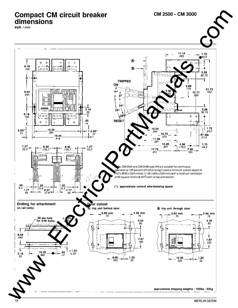
Compact CM circuit breaker dimensions inch I mm
+ 6.18 156
t -9.44 240
t -2.oo· l 1 5.35 1 2.oo· 51 I 390 51 I ., , 16.45
418
1 .27 1 .27 32.3 32.3
Door cutout
CM 2500 - CM 3000
1 1 . 14 283
TRIPPED ON f f -
14°
f SO \ 24°
-
29°\ '
\ofF/ RESET
__ 1 0.39 264
1 7.75 451
note: CM 2500 and CM 3000 type HH are suitable for continuous operation at 1 00 percent of frame rating if used a minimum cubicle space of
H43 x W30 x 020 inches (1 1 00 x BOO x 500 mm) with a minimum ventilation
of 90 square inches (6 dm2) both at top and bottom.
(•): approximate control wire-bending space
21 .73 552
L 1 .75 44.5
Drilling for attachment on rail (only) @ trip unit behind door @ trip unit through door
1 8
.38 dia hole for 5/16 bolts
,;;; 1 .20 ,;; 30
-r---t-2.95 min
I I 75 I I
-t------t-2.95 min
I I 75 I I 3,34
85
4------+-- 2.95 min I I 75 I I
-t------t- 2.95 min
I I 75 I I 3.34
85
approximate shipping weights : 1 951bs - 89kg
MERLIN GERIN www . El
ectric
alPar
tMan
uals
. com

Compact CM circuit breaker dimensions inch I mm
motor operator
f- �9 • = f-
1 2.20 310
1 o ;o1 l o o ol lo o o � � � 1 1 .41
I 36 8.66 -------<�4-1.._
t---- 220 ·86
1------ 14.1 7 -----++___,22
360 .60 15
neutral sensor
.78 20
1 .68.._....��,_;· 78 42.8 20
2.36 60
3.93 100
2.47 +----1-�
1 .6 62.8 42.2
MERLIN GERIN
I.....
.47 dia 0 12
.59 15
l""r--
L
......
l r
motor operator neutral sensor
-
n I
J
J I u
--
10 .39 -264 13 . 15 334
19 www . El
ectric
alPar
tMan
uals
. com
Compact CM circuit breaker appendix
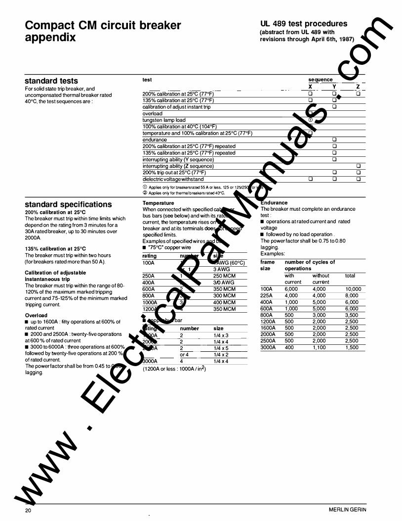
standard tests test
For solid state trip breaker, and uncompensated thermal breaker rated 200% calibration at 25°C (77°F)
40°C, the test sequences are : 1 35% calibration at 25°C (77°F) calibration of adjust instant trip overload tungsten lamp load 1 00% calibration at 40°C ( 1 04°F) temperature and 1 00% calibration at 25°C (77°F) endurance 200% calibration at 25°C (77°F) repeated 1 35% calibration at 25°C (77°F) repeated interrupting ability (Y sequence) interrupting ability (Z sequence) 200% trip out at 25°C (77°F) dielectric voltage withstand
UL 489 test procedures (abstract from UL 489 with revisions through April 6th, 1 987)
sequence
X y 0 0 0 0
0 0 (j) (i) 0
0 0 0 0
0 0 0
z 0
0 0 0
CD Awlies only for breakers rated 55 A or less, 125 or 1251250V or less
standard specifications 200% calibration at 25°C The breaker must trip within time limits which depend on the rating from 3 minutes for a 30A rated breaker, up to 30 minutes over 2000A.
1 35% calibration at 25°C The breaker must trip within two hours (for breakers rated more than 50 A).
Calibration of adjustable instantaneous trip The breaker must trip within the range of 80-1 20% of the maximum marked tripping current and 75-125% of the minimum marked tripping current.
Overload • up to 1600A : fifty operations at 600% of rated current • 2000 and 2500A : twenty-five operations at 600 % of rated current • 3000 to 6000A : three operations at 600% followed by twenty-five operations at 200 % of rated current. The power factor shall be from 0.45 to 0.50 lagging.
20
(i) Awlies only for thermal breakers rated 40"C.
Temperature When connected with specified cables or bus bars (see below) and with its rated current, the temperature rises on the breaker and at its terminals does not exceed specified limits. Examples of specified wires and bus • "?Sac• copper wire
rating number size
1 00A 1 1 AWG (60°C) or 3 AWG
250A 1 250 MCM 400A 2 3/0 AWG 600A 2 350 MCM 800A 3 300 MCM 1 000A 3 400 MCM 1 200A 4 350 MCM
• copper bus bar
rating number size
1600A 2 1 /4 x 3 2000A 2 1 /4 X 4 2500A 2 1/4 x 5
or 4 1/4 x 2 3000A 4 1 /4 X 4
( 1 200A or less : 1 OOOA I in2)
Endurance The breaker must complete an endurance test : • operations at rated current and rated voltage • followed by no load operation . The power factor shall be 0. 75 to 0.80 lagging. Examples:
frame number of cycles of size operations
with without total current current
1 00A 6,000 4,000 1 0,000 225A 4,000 4,000 8,000 400A 1 ,000 5,000 6,000 600A 1 ,000 5,000 6,000 800A 500 3,000 3,500 1 200A 500 2,000 2,500 1600A 500 2,000 2,500 2000A 500 2,000 2,500 2500A 500 2,000 2,500 3000A 400 1 , 1 00 1 ,500
MERLIN GERIN www . El
ectric
alPar
tMan
uals
. com

Compact CM circuit breaker appendix
Interrupting ability (Y sequence) After endurance tests and calibrations repeated, the breaker completes an opening followed by a close-open operation (0-t-CO), with specified current. Examples for three pole breakers:
frame rating RMS Sym. Amps (3-pole 0-t-CO)
100A <D 3,000 225A 3 000 400A 5,000 600A 6,000 SODA 10,000 1 200A 14,000 1600A 20,000 2000A 25,000 3000A 35,000 <D Nx:Ne 25/JV.
Interrupting ability (Z sequence) A 3-pole breaker rated 240, 480 or 600V have to complete an opening operation and a close-open operation (0-t-CO) on each pole, at rated voltage, followed by an opening operation (0) using all the three poles for the frame sizes up to 1 200A, an additional close-open operation on the three poles is required). Examples for 3-pole breaker :
frame rating RM Sym. Amps
each common pole 0-t-CO 0 0-t-CO
100 to 800A 8,660 1 0,000 1 000 to 1 200A 1 2, 1 20 1 4,000 1600A 14,000 20,000 2000A 14,000 25,000 3000A 25,000 35,000
MERLIN GERIN
Dielectric After tests, the breaker must withstand for one minute a voltage of 1 OOOV plus twice the rated voltage between : • line and load terminals • terminals of opposite polarity • live parts and the overall enclosure
Optional tests : • high available fault current Breakers having passed all the standard tests may have the UL label applied at higher values than the standard. Test sequence is as follow : o 200 % calibration o interrupting capacity : an opening operation followed by a close open operation (0-t-CO) on all poles are performed on the circuit breaker. The power factor over 20000A shall be 0. 1 5 to 0.2 1agging. 0 trip out at 250% o dielectric at twice the rated test voltage.
• 1 00% rated Breakers having passed all the standard tests may have the UL label applied to use the circuit breaker in an enclosure, when carrying 1 00% of its maximum rating. The circuit breaker is submitted to additional temperature tests performed as in Standard tests, except that the breaker is installed in an enclosure. The dimensions and possible ventilations shall be recorded and shall be marked on the breaker.
U L 489 test procedures (abstract from UL 489 with revisions through April 6th, 1 987)
tests on accessories Shunt trip and undervoltage trip These devices are submitted to temperature, overvoltage, operation, endurance and dielectric tests. • Overvoltage test It checks that the device is capable of withstanding 1 1 0% of its rated voltage continuously without injury (this test does not apply to a shunt trip with an "a" contact connected in series). • Operation The shunt trip must operate at 75% of its rated voltage (except that shunt trip devices for use with ground fault protection shall operate at 55%). The undervoltage trip must trip the breaker when the voltage is between 35 and 70% of its rated voltage and shall seal (i .e. : the breaker cannot be turned on ON position) when the voltage is at 85% or more of its rated voltage. • Endurance The device must be capable of performing successfully for 10% of the number of ''with current" operations of the breaker.
Auxiliary and alarm switches Auxiliary and alarm switches must be submitted to temperature, overload, endurance and dielectric tests. • Overload test The test consists of fifty operations making and breaking 1 50% of rated current at rated voltage, with a 75-80% power factor in AC and non inuductive load in DC. • Endurance The switch must make and break its rated current at rated voltage, with a 75-80% power factor in AC, and non inductive load in AC for 1 00% of the number of operations ''with current" for auxiliary switches, and 1 0% of this number for alarm switches.
21 www . El
ectric
alPar
tMan
uals
. com
Compact CM circuit breaker appendix
recommended inspection intervals Merlin Gerin circuit breakers are designed to be maintenance-free. However, all equipment with moving parts requires periodic inspection to ensure optimum performance and reliability. We recommend that the circuit breakers be routinely inspected six months after installation, followed by annual inspection. Intervals can vary depending on your particular experience.
inspection of terminals Connections to circuit breaker • terminals could be inspected. If there is discoloration due to overheating, the joint should be dissassembled and the surface cleaned before reinstallation. It is essential that electrical connections be made carefully in order to prevent overheating. • Check for terminal tightness.
cleaning Remove the dust and dirt that have accumulated on the circuit breaker surface and terminals.
mechanical checks Even over long periods circuit breakers are not often required to operate on overload or short-circuit conditions. Therefore it is essential to operate the breaker periodically. To trip the breaker, push the push-totrip button.
22
insulation resistance tests When breakers are subjected to severe operating conditions, insulation resistance test should be performed as indicated in NEMA standard publication no AB2-1980. An insulation resistance test is used to determine the quality of the insulation between phases and phase to ground. The resistance test is made with a DC voltage higher than the rated voltage, to determine the actual resistance of the insulation. The most common method employs a "megger" type instrument. A 1 OOOV instrument will provide a more reliable test because it is capable of detecting tracking on insulated surfaces. Resistance values below 1 megohm are unsafe and should be investigated. An insulation test should be made : • between line and load terminals of individual poles with the circuit breaker contacts open. • between adjacent poles and from poles to the metallic supporting structure with the circuit breaker contacts closed. The latter test may be done with the circuit breaker in place after the line and load conductors have been removed, or with the circuit breaker bolted to a metallic base which simulates the in-service mounting.
electrical tests These tests require equipment for conducting pole resistance, overcurrent and instantaneous tripping, in accordance with NEMA standard publication no AB 2. They are not within the scope of normal field operation.
routine and maintenance guidelines
Important : All tests must be made on circuit breakers which have been de-energized, and disconnected so as to prevent accidental contact with live parts.
Caution : Since molded case circuit breakers contain factory-sealed and calibrated elements, it is essential that the seal is not broken and the circuit breaker is not tampered with. M olded-case circuit breakers should not be field adjusted or repaired. In the case of malfunction, the circuit breaker should be replaced or repaired at the Merlin Gerin factory, or by an authorized representative.
MERLIN GERIN www . El
ectric
alPar
tMan
uals
. com
Compact CM circuit breaker appendix
application of 100% rated breakers
standard or 100% rated breakers ? There is no fixed rule regarding the relative advantages of these two breakers. However, the greater the continuous load is, the more economical breakers and busbars become.
100% rated breakers are designed and U L listed to carry 1 00 % of their name plate current rating when enclosed.
They have a special marking which indicates that they are suitable for continuous operation at 1 00% of frame rating if used in a minimum enclosure, with a m inimum ventilation.
The National Electrical Code in section 220-1 O(b) directs us to calculate the feeder and breaker ratings.
Nationa l Electrical Code section 220-10(b) extract :
"(b) continuous and non continuous toads. Where a feeder supplies continuous loads or
any combination of continous and non continuous load, neither the ampere rating of the overcurrent device nor the ampacity of the feeder conductors shall be Jess than the non continuous load plus 125 percent of the continuous load.
Exception : Where the assembly including the overcurrent devices protecting the feeder(s) are listed for operation at 100 percent of their rating, neither the ampere rating of the overcurrent device nor the ampacity of the feeder conductors shall be Jess than the sum of the conu"nuous load plus the noncontinuous load. •
with a standard rated breaker :
breaker and feeder = 1 00% x non continuous load + 1 25% x continuous load
with a 100% rated breaker :
breaker and feeder = 1 00% x non continuous load + 1 00% x continuous load
In other words for the same low voltage distribution system the selection of a 100% rated circuit breaker can be more economical and does not affect breaker reliability.
Definition of conti nuous and non conti nuous load The UL Electrical Construction Materials Directory contains a clear, simple rule in the instructions under "Circuit Breakers, Molded Case". It says :
"Unless otherwise marked, circuit breakers should not be loaded to exceed 30 percent of their current rating, where in normal operation the load will continue for three or more hours".
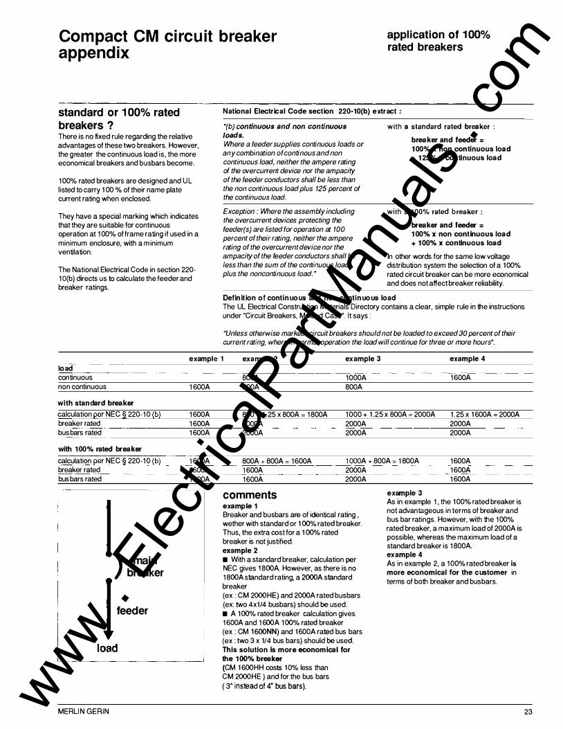
example 1 example 2 example 3 example 4
load continuous non continuous
with standard breaker
calculation per NEC § 220-10 (b) breaker rated bus bars rated
with 100% rated breaker
calculation per NEC § 220-10 (b) breaker rated bus bars rated
) main breaker
1 600A
1 600A 1 600A 1 600A
1 600A 1 600A 1 600A
I feeder
l ____ lo�ad ________ �
MERLIN GERIN
800A 1000A 1600A 800A 800A
800 + 1 .25 X 800A = 1 800A 1000 + 1 .25 X 800A = 2000A 1 . 25 X 1 600A = 2000A 2000A 2000A 2000A 2000A 2000A 2000A
800A + 800A = 1600A 1 OOOA + 800A = 1 800A 1600A 1 600A 2000A 1600A 2000A
comments example 1 Breaker and busbars are of identical rating , wether with standard or 1 00% rated breaker. Thus, the extra cost for a 1 00% rated breaker is not justified. example 2 • With a standard breaker, calculation per NEC gives 1 800A. However, as there is no 1 800A standard rating, a 2000A standard breaker (ex : CM 2000HE) and 2000A rated busbars (ex: two 4x1/4 busbars) should be used. • A 100% rated breaker calculation gives 1600A and 1 600A 1 00% rated breaker (ex : CM 1 600NN) and 1600A rated bus bars (ex : two 3 x 1/4 bus bars) should be used. This solution Is more economical for the 1 00% breaker (CM 1 600HH costs 10% less than CM 2000HE ) and for the bus bars ( 3" instead of 4" bus bars).
1600A 1 600A
example 3 As in example 1 , the 100% rated breaker is not advantageous in terms of breaker and bus bar ratings. However, with the 100% rated breaker, a maximum load of 2000A is possible, whereas the maximum load of a standard breaker is 1 800A. example 4 As in example 2, a 100% rated breaker is more economical for the customer in terms of both breaker and bus bars.
23 www . El
ectric
alPar
tMan
uals
. com
Compact CM circuit breaker appendix
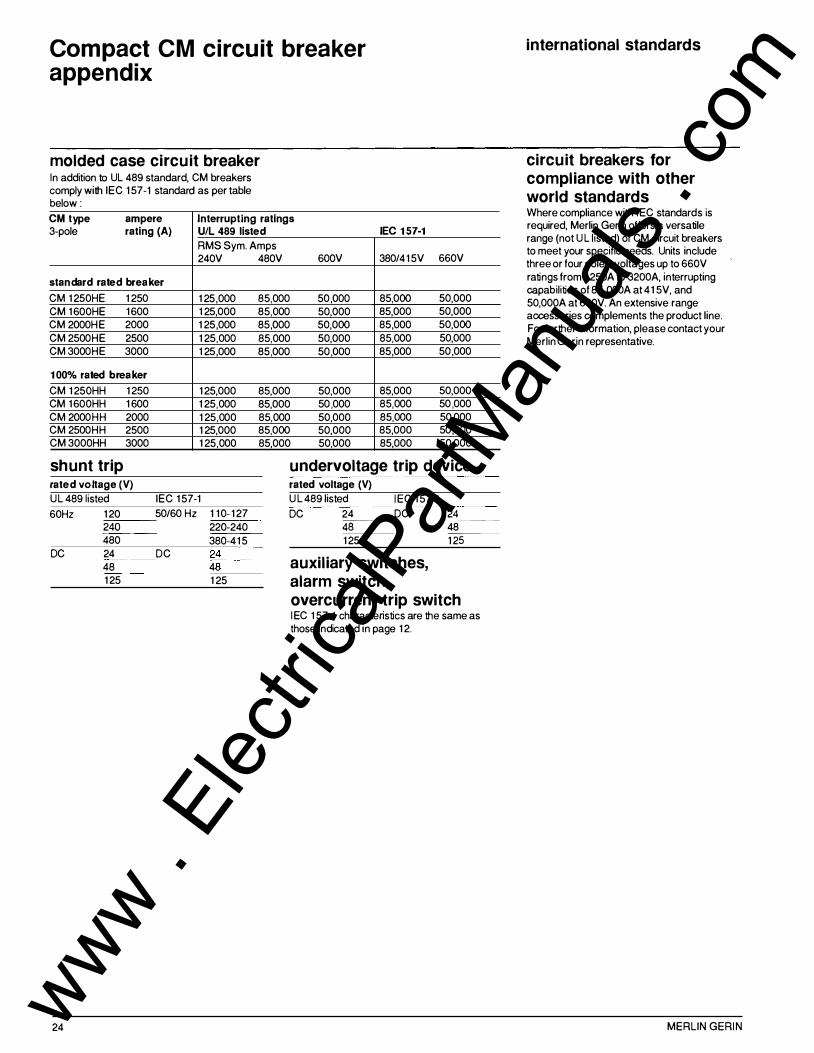
molded case circuit breaker In addition to UL 489 standard, CM breakers comply with IEC 1 57-1 standard as per table below :
CM type ampere Interrupting ratings 3-pole rating (A) U/L 489 listed IEC 1 57-1
RMS Sym. Amps 240V
standard rated breaker
CM 1 250HE 1 250 1 25,000 CM 1600HE 1600 1 25,000 CM 2000HE 2000 1 25,000 CM 2500HE 2500 1 25,000 CM 3000HE 3000 1 25,000
1 00% rated b reaker
CM 1 250HH 1 250 1 25,000 CM 1600HH 1 600 1 25,000 CM 2000HH 2000 1 25,000 CM 2500HH 2500 1 25,000 CM 3000HH 3000 1 25,000
shunt trip rated voltage (V)
UL 489 1isted IEC 1 57-1
60Hz 1 20 50/60 Hz 1 10- 1 27 ::-24:::0:---- 220-240 480 380-41 5
480V 600V 380/41 5V 660V
85,000 50,000 85,000 50,000 85,000 50,000 85,000 50,000 85,000 50,000 85,000 50,000 85,000 50,000 85,000 50,000 85,000 50,000 85,000 50,000
85,000 50,000 85,000 50,000 85,000 50 ,000 85,000 50 ,000 85,000 50,000 85,000 50,000 85,000 50,000 85,000 50,000 85,000 50,000 85,000 50,000
undervoltage trip device rated voltage (V)
U L 489 1isted IEC 1 57-1
DC 24 DC 2=-.c4c.__�-""48::---- 48 1 25 -,-12::-:5:----
DC 24 DC 24 48 4
�8:
---- auxiliary switches, alarm switch, overcurrent trip switch
24
1 25 1 25
I EC 1 57-1 characteristics are the same as those indicated in page 1 2.
international standards
circuit breakers for compliance with other world standards Where compliance with IEC standards is required, Merlin Gerin offers a versatile range (not U L listed) of CM circuit breakers to meet your specific needs. Units include three or four poles, voltages up to 660V ratings from 1 250A to 3200A, interrupting capabilities of 85,000A at 41 5V, and 50,000A at 660V. An extensive range accessories complements the product line. For further information, please contact your Merlin Gerin representative.
MERLIN GERIN www . El
ectric
alPar
tMan
uals
. com
MERLIN GERIN I NC. 5000 Highlands Pkwy. Suite 1 50 SMYRNA. GA 30082 tel . (404) 432.2744 fax (404) 432.9 179
AC0036/1 E
As standard specifications and designs change from time to time. please ask for confirmation of t�e information given in this publication.
photos : Merlin Gerin, B. Maurice design by AMEG - ABT - Y. Marchand IPV - 06/89 - printed by In
www . El
ectric
alPar
tMan
uals
. com