collins kwm-380 · 2400 hz with not more than 5 ... output pawer. ..... 100 w pep, nominal in cw or...
TRANSCRIPT

Collins KWM-380 owner's manual

523-0769877-002217 2nd Edition, 1 January 1981
owner's manual
Collins KWM·380
Transceiver
Collins Telecommunications Products Division
Electronic Systems Group Rockwell International
Cedar Rapids, Iowa, 52406

WARNING
THIS TRANSCEIVER, WHEN TRANSMITTING INTO AN ANTENNA EITHER DIRECTLY OR THROUGH AN ASSOCIATED ANTENNA COUPLER AND/ OR POWER AMPLIFIER, MAY PRODUCE AN ELECTROMAGNETIC FIELD NEAR THE ANTENNA THAT IS IN EXCESS OF THE OCCUPATIONAL SAFETY AND HEALTH ADMINISTRATION (OSHA) MAXIMUM RECOMMENDED LIMITS.
introduction
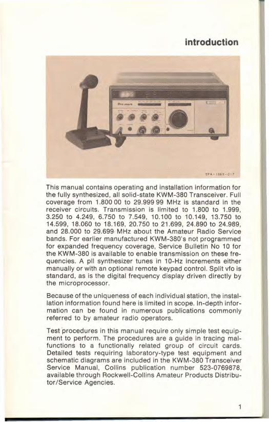
This manual contains operating and instaliation information for the fully synthesized, all solid-state KWM-380 Transceiver. Full coverage from 1.80000 to 29.99999 MHz is standard in the receiver circuits. Transmission is limited to 1.800 to 1.999, 3.250 to 4.249, 6.750 to 7.549, 10.100 to 10.149, 13.750 to 14.599, 18.060 to 18.169, 20.750 to 21.699, 24.890 to 24.989, and 28.000 to 29.699 MHz about the Amateur Radio Service bands. For earlier manufactured KWM-380's not programmed for expanded frequency coverage, Service Bulletin No 10 for the KWM-380 is available to enable transmission on these frequencies. A pll synthesizer tunes in 10-Hz increments either manually or with an optional remote keypad control. Split vfo is standard, as is the digital frequency display driven directly by the microprocessor.
Because of the uniqueness of each individual station, the installation information found here is limited in scope. In-depth information can be found in numerous publications commonly referred to by amateur radio operators.
Test 'procedures in this manual require only simple test equipment to perform. The procedures are a guide in tracing malfunctions to a functionally related group of circuit cards. Detailed tests requiring laboratory-type test equipment and schematic diagrams are included in the KWM-380 Transceiver Service Manual , Collins publication number 523-0769878, available through Rockwell-Collins Amateur Products Distributor/Service Agencies.
1

specifications
Physical
Size ............................. .. ....... .. 394 mm (15.5 in) wide. 165 mm (6.5 in) high, (does not include 25 mm (1 in) feet normally attached). 457 mm (18.0 In) deep
Weight ................................... 21 .8 kg (48 Ibs) max
Primary power ................ ...... .... Strappable for : 105, 115, 1251 21 D. 220, 230, 240, 250 V ±5%, 50 to 60 Hz; or 12 to 15 V dc. 120 W max in receive; 600 W max in transmit
Receiver
Frequency ...................... .. . 1.6 to 29.99999 MHz, tunable in 10-Hz steps
Modes ............................ ...... .. USB, lSB, AM, and CW
Sensitivity (at antenna terminals) ............ .. .. .. .. ......... 0.5 jlV or better for 10 dB
(s+n)/n, 2.0 to 30.0 MHz; 1.0 jlV or better 1.8 to 2.0 MHz
Selectivity (3-dB min bandwidth) .......................... .. Selectable
8 kHz *6 kHz 2.1 kHz
*1.7 kHz *360 Hz ·140 Hz
If and image rejection ....... .. . Greater than 60 dB
·Optional filters
2

Intermodulation d istortion ... . -50 dB or better for two signals of -10 dB mW each, 20 kHz apart
AGe .. ... .. .. .. .. .. .. .. .. .. .. .. .. .. .. .. .... Audio output variation not more than 8 dB for 4-J.N to 200-mV open circuit rf input variation
Aud io output ......................... Not less than 3.5 W into 4-ohm load, at 1 kHz, at not more than 10% total harmonic distortion
Transmitter
Frequency (Complete coverage shown may requ ire installation of KWM-380 Service
Line audio output: -10 dB mW nominal into 600 ohms
Frequency response: 300 to 2400 Hz with not more than 5 dB variation
Bulletin No 10) .... .................. 160- through 10-m amateur bands, tunable in 10-Hz steps
"Future amateur bands
160 m 80175 m
*"30 m *"17 m "*12 m
40 m 20 m 15 m 10 m
1.800- 1.999 MHz 3.500- 4.000 MHz
10.100-10.149 MHz 18.068-18.169 MHz 24.890-24.989 MHz
7.000- 7.300 MHz 14.000-14.350 MHz 21 .000-21.450 MHz 28.000-29.699 MHz
3

MARS ±2S0 kHz either side of 80 - 15 m bands, except 30 mand17m bands
Modes .................................... USB, LSB, and CW
Output pawer. ....................... 100 W pep, nominal
In CW or ATTY, automatic turndown to 50 W after 10 seconds, 50 percent duty cycle, key down 15 minutes, max.
With optional blower kit installed, power is 100 W continuous; key down 1 hour, max, at 25 "C; 30 minutes, max, at 50 "c for all modes.
Unwanted signal suppression
Carrier ................................... -50 dB or better
Undesired sideband, l-kHz ref ............................... -55 dB or better
Harmonics (all) ... ... .... .... .... .. . -40 dB or better
Mixer products ..................... -50 dB or better
Third order distortion ........... 25 dB below each tone of two-tone test
Synthesizer accuracy and stability .............................. Accuracy within ±5 Hz after
10 minutes warm-up when 39.6- and 0.455-MHz oscillators are set to within ±3 Hz
4

Stability within ±150 Hz over temperature range of 0 to 50 °c
At load .. .... .. ..... .................. .. ... . 50 ohms, nonreactive. Full power output with vswr of 2:1 or less. Automatic power output turndown with vswr greater than 2:1.
Audio inputs
Microphone ................... .. ..... Low or high impedance, dynamic
Line ........................... .. .. .. .... .. . 600 ohm, unbalanced; 40-mV input sufficient for full rf power output
5

INSTALLATION
unpacking
The KWM·3BO may be shipped in two separate cartons, depending on the shipping carrier's requirements. One con· tains the power transformer, the other contains the transceiver. After carefully unpacking the cartons, check to be sure no ship· ping damage is evident. Should any damage be apparent, save the cartons and notify the delivery carrier immediately to file claim for damage.
The KWM·3BO is shipped strapped for 115 V ac operation.
power transformer installation
If the power transformer has been shipped separately, it can be quickly installed in five steps. A 3/ B-in open-end wrench, no 12 (3 /B- in) nutdriver , and a Phillips screwdriver are the only tools needed.
• Using the screwdriver, remove four screws from the bottom of the transceiver (near the rubber feet at each corner) and slide the dust cover off over the heat sink.
• Remove the front one of the two PhillipS· head screws secur· ing the front panel braces to the sides of the chassis and tilt the panel forward .
• Turn the transformer so terminals 1 through B face the front panel. With the nutdriver, remove the four hexposts and lockwashers from the chassis mounting studs in the right front corner of the chassis and set the transformer over the studs.
6
• Using the wrench and nutdriver, secure the transformer to the studs with the four lockwashers and hex posts.
• Electrically connect the transformer to the transceiver with the two attached polarized connectors. Reattach the front panel , then replace the dust cover. Be careful when replacing the dust cover to avoid pinching or dislodging cables.
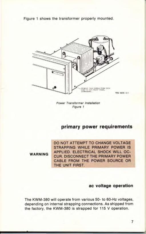
Figure 1 shows the transformer properly mounted.
WARNING
Power Trensformer Ins/a ile/ion FiQur9 1
primary power requirements
DO NOT ATTEMPT TO CHANGE VOLTAGE STRAPPING WHILE PRIMARY POWER IS APPLIED. ELECTRICAL SHOCK WILL OCCUR. DISCONNECT THE PRIMARY POWER CABLE FROM THE POWER SOURCE OR THE UNIT FIRST.
ac voltage operation
The KWM-380 will operate from various 50- to 60-Hz voltages, depending on internal strapping connections. As shipped from the factory, the KWM-380 is strapped for 115 V operation.
7

For input voltages listed, refer to figure 2 and strap T81 as follows:
WIRE 105 115 125 210 220 230 240 250
BLACK 7 7 7 6 6 5 5 4
YELLOW 3 2 1 3 2 2 1 1
RED 6 5 4 3 2 2 1 1
Determine the average ac voltage at the primary power outlet where the transceiver is to be used. Remove the chassis dust cover and locate the protective cover plate near the left rear corner as viewed with chassis upside down. Remove the cover plate and reler to the preceding chart to make the connections indicated for the voltage nearest the primary power outlet voltage. If the outlet voltage is approximately halfway between two voltages listed, strap T81 for the lower voltage.
Figure 2 shows T81 correctly strapped for 105 or 240 volts.
8
SLACK VIOLET
STRAPPING FOR 10~ V AC
PROTECTIVE COVER PLAT(
Bl..ACII. VIOLET
STRAPPING FOR 240 V AC
BOTTO'"' lEFT REAR CORNER OF'TlIA NSC[lV£R
TBI Strapping lor 105 YOrrS or 240 Yotts Figure 2
TPA·H;~!-Oll

de Yoltage operation
The KWM·380 will also accept 12 to 15 volts de for backup emergency power. The primary power connector must be strapped as shown in figure 3. Power requirements are nominally 3 A in receive and 20 A in transmit.
RENt (WIRING SIDE) VIEW OF CABLE CONNECTOR
AC HIGH ~~~~~±=±:t SAF ETY GRO UNl) AC NE UTRAL
I 10 0 ==
AC CONNECTOR
-£~-]" .. r= . voe 9 9 II
8 10 0 12 = (JUIllI'ER)
OC CONNECTOR
TPA ·16~4 ·011
Power Connector Str8pping lor AC or DC Oper8tion Figu re :3
operating location
The normal operating location should be chosen so the transceiver is away from heat vents and normal airflow around it is unobstructed. Do not lay objects on top or against the sides. It is especially important that the heat sink have a free flow of air about it. An automatic turndown circuit will reduce the rf output power if the heat sink overheats. This is for self-protection of the power amplifier output stages.
The AC-2808 Blower Kit is available for attaching to the heat sink. This blower supplies cooling air to permit normal operation in close quarters or high-duty cycle operation.
9
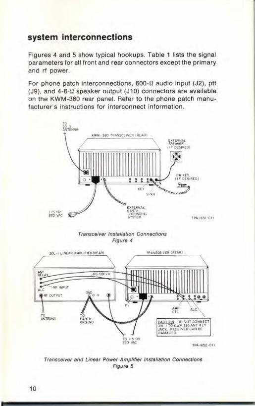
system interconnections
Figures 4 and 5 show typical hookups. Table 1 lists the signal parameters for ali front and rear connectors except the primary and rf power.
For phone patch interconnections, 600-0 audio input (J2), ptt (J9), and 4-8-0 speaker output (J10) connectors are available on the KWM-380 rear panel. Refer to the phone patch manufacturer's instructions for interconnect information .
10
180 U10 ""·
Transceiver Ins ta llation Connections Figure 4
I I I (
Transceiver and Linear Power Amplifier Installa tion Connections Figure 5
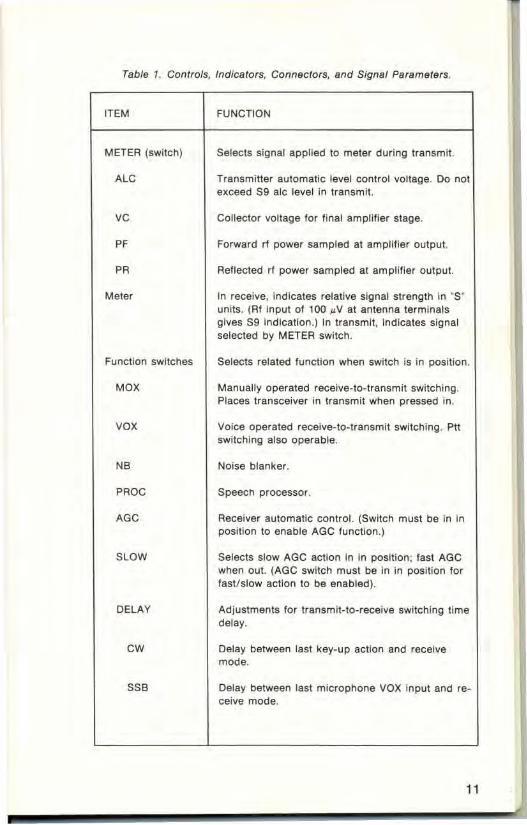
Tabla 1. Controls, Indicators, Connectors, and Signal Parameters.
ITEM
METER (switch)
ALe
ve
PF
PR
Meter
Function switches
MOX
vox
NB
PRoe
AGe
SLOW
DELAY
ew
SSB
FUNCTION
Selects signal applied to meter during transmit.
Transmitter automatic level control voltage. 00 not exceed 59 alc level in transmit.
Collector voltage for final amplifier stage.
Forward rf power sampled at amplifier output.
Reflected rl power sampled at amplifier output.
In receive, indicates relative signal strength In '5' units. (RI Input Of 100 IJ.V at antenna terminals gives S9 indication.) In transmit, indicates signal selected by METER switch.
Selects related lunction when switch is in position.
Manually operated receive-to-transmit switching. Places transceiver in transmit when pressed in.
Voice operated receive-to-transmit switching. Ptl switching also operable.
Noise blanker.
Speech processor.
Receiver automatic control. (Switch must be In in position to enable AGe function .)
Selects slow AGC action in in position; last AGe when out. (AGe switch must be in in pOsition lor lastlslow action to be enabled).
Adjustments lor transmit-to-receive switching time delay.
Delay between last key-up action and receive mode.
Delay between last microphone VOX input and receive mode.
11

Table 1. Controls, Indicators, Connectors, and Signal Parameters (ContJ-
ITEM
GAIN
vox
ANTI
Frequency readout
Frequency control switches
SYNC
LOCK
,(lett)
r(rlght)
POWER
Tuning knob
SPOT
VFO
A
12
FUNCTION
Adjusts levels at which receive-to-transmit switching occurs.
Voice or line audio input signals.
Speaker-to-microphone signals.
Displays frequency in IO-Hz increments.
Selects frequency increments affected by tuning knob. Continuous tuning for any increment with roll-around at end limits.
I-MHz increments.
Loads displayed frequency in nonselected vfo register to synchronize both vlo frequencies.
Dial lock prevents tuning knob from changing frequency when rotated. Release by pressing in any increment switch.
I-kHz increments.
100-Hz increments,
10-HZ Increments,
Primary power switch.
Frequency selection control. (Provides 200 Increments per revolution for all except MHz steps atl0 increments per revolution.) Works in conjunctiOn with switches above knob.
In CW mode only, enables SOO-Hz tone to which received CW tone is matched to spot transmitted frequency to exact received frequency.
Selects frequency-storage register.
A register . Transmit and receive on same frequency.

Tabla 1. Controls, Indicators, Connectors, and Signal Parameters (Cont).
ITEM
B
RA-TB
RB-TA
SELECTIVITY
PBT (small knob)
BW (large knob)
'.0
2.2
OPT 1,2,3
MODE
cw
USB
LSB
AM RCV
GAIN
AF (small knob)
RF (large knob)
FUNCTION
B register. Transmit and receive on same frequency.
Receive on A register frequency-transmit on B regIster frequency.
Receive on B register frequency-transmit on A register frequency.
Controls selectivity of receiver.
Passband tuning. Used to select USB. LSB, or CW during receive mode. Continuously varies position of passband (bandwidth selected by BW control) within 8-kHz passband of first if fil ter.
Selects filter bandwidth.
8.0-kHz filter (for AM, also selects optional 6-kHz AM filter if installed).
2.2-kHz filter (for normal SSB).
Three positions for optional filters
Selects mode of transmit operation.
Continuous wave.
Upper Sideband. }
Lower sideband.
Receive sideband determined by setting of PBT control.
Amplitude modulation in receive only. Transmitter does not operate in AM mode.
Adjusts gain of receiver circuits.
AI amplifier gain.
Rf amplifier gain.
13

Tabla 1, Controls, Indicators, Connectors, and Signal Parameters (Cont1-
ITEM
MIC/CARRIER
PHONES (mates with PJ-055)
MIC (mates with PJ-068)
Antenna (mates with PL-259)
Fuse
J' Ground
AUD IN (J2) (mates with phono plug)
ALC (J3) (mates with phono plug)
ANT RLY (J4) (mates with phono plug)
14
FUNCTION
In sideband operation adjusts microphone amplifier gain. In CW operation adjusts rf carrier level. 00 not exceed 59 alc indication.
Output jack for low-Impedance (4-to 8-0) headphones. Connecting phones Inhibits speaker and SPKR (on rear panel) outputs. Tip- receiver audio; 4- to 8-fI impedance, up to
3-W output Barrel-ground
Input jack for high- or low-impedance, dynamic microphone. Jack is also wired for ptt signal. Tlp-ptt line; ground to transmit Ring-microphone audio; high- or low-impedance
input, approx 5 mV in for full power output Barrel-common ground
Rf connector (type 50-239 with Tellon insert) for coaxial cable connection to antenna or linear amplifier.
Primary power fuse (8 A for 110 V. 4 A lor 220 V).
Primary power connector.
Stud lor earth-ground connection.
Input for 600-ohm, unbalanced line audio: 40-mV input produces 100-W rl output.
Negative ALC input signal Irom external power amplifier.
Receive contacts 01 Internal antenna transfer relay.
CAUTION: Do not connect linear amplifier control to J4. Damage to the receiver may result. External receiver may be connected to J4.
(Jumpered to RCV IN (J8) il separate receive antenna not used. Cut internal Jumper II separate antenna used.)
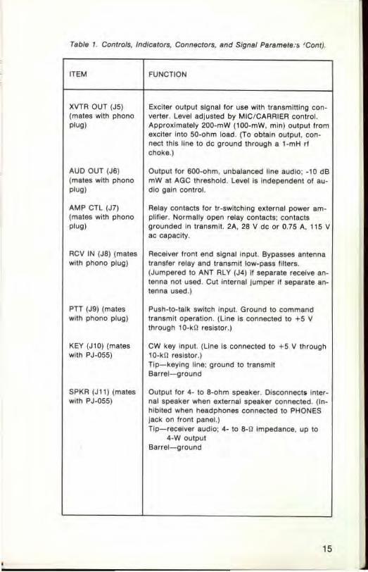
Tabla 1. Controls, Indicators, Conneclors, and Signal Paramate.-, ' Cont).
ITEM
XVTR OUT (J5) (mates with phono plug)
AUO OUT (J6) (mates with phono plug)
AMP CTl (J7) (mates with phono plug)
RCV IN (J8) (mates with phono plug)
PH (J9) (mates with phono plug)
KEY (Jl0) (mates with PJ·055)
SPKR (Jlt) (mates with PJ·055)
FUNCTION
Exciter output signal lor use with transmitting con· verter. Level adjusted by MIC/CARRIER control. Approximately 200-mW (100·mW, min) output Irom exciter Into 50·ohm load. (To obtain output, con· nect this line to dc ground through a ,-mH rl choke.)
Output lor 6QO..ohm, unbalanced line audio; ·10 dB mW al AGC Ihreshold. Level Is Independent of au· dlo gain control.
Relay contacts lor tr·switChing external power am· plilier. Normally open relay contacts: contacts grounded in transmit. 2A, 28 V dc or 0.75 A, tt5 V ac capacity.
Receiver Iront end signal input. Bypasses antenna transfer relay and transmit low·pass IIIters. (Jumpered to ANT RlY (J4) if separate receive an· lenna not uSed. Cut internal Jumper II separate an· tenna used.)
Push·to·talk switch input. Ground to command transmit operation. (Line is connected to +5 V through to·kO resistor.)
CW key Input. (Line is connected to +5 V through 10·kO resistor.) Tip-keying line; ground to transmit Barrel- ground
Output for 4· 10 8·ohm speaker. Disconnects Inler· nal speaker when external speaker connected. (tn· hibited when headphones connected to PHONES Jack on front panel.) Tip-receiver audio: 4· to 8·0 Impedance, up to
4·Woutput Barrel- ground
15
grounding
The importance of a good ground system cannot be overemphasized. All units of the system should have ground interconnections through heavy wire (#12 AWG or larger) or ground strap (6-mm (1/4 -in) wide or larger) between ground lugs. Use as short a length of ground wire or braid as practical between units or external ground.
Connect the KWM-380 ground lug on the rear to a good earth or water-pipe ground.
Before using a water-pipe ground, check to make sure that no plastic, rubber, or other such insulating sections will interrupt the electrical continuity to ground. Install a jumper around any insulating sections found. Use heavy copper wire or ground braid and metal pipe clamps.
antennas
The antenna is one of the most important parts in the performance of any radio communications system. System performance is directly related to the efficiency of the antenna. Because each individual installation has unique characteristics, various types of antennas, their characteristics, and installation information cannot be covered in this manual. A number of excellent reference works on antennas are available.
The KWM-380 is designed to operate into a nonreactive rf load of 50 ohms. Impedance mismatches producing vswr's lower than 2:1 are acceptable. For vswr's 2:1 or greater, the transceiver power amplifier output is automatically reduced in proportion to the reflected power.
16

OPERATION
introduction
Controls on the KWM-3BO have been labeled so that their function is self-explanatory. After referring to figures 6 and 7 and table 1, many operators will need no further explanation. The following paragraphs summarize operation of several of the controls and give check lists for initial control settings for each operating mode.
The large tuning knob and row of switches immediately above it control the transceiver frequency selection. When power is applied to the transceiver, the frequency is automatically set to 15.00000 MHz. Frequency data is not retained in the vfo registers when power Is turned off.
There is no need for a bandswitch since selection of the MHz tuning increment permits tuning from 0 to 29 MHz in three turns of the knob.
frequency selection
TPA- 1667- 0 11
This rate Is effective for the MHz digits only. Selecting other increments automatically switches the tuning rate to 200 steps per turn. For example, selecting the 1 aO-Hz increment gives 20 kHz per revolution of the tuning knob.
When a switch is depressed to select a frequency increment to be changed, that and all higher increments will change as the tuning knob rotates. For example, if the 100-Hz Increment is selected, the 10-Hz digit remains where last set. Rotating the tuning knob clockwise causes the 100-Hz digits to increment
17
up through 9, index the 1-kHz digit by one, and roll around to 0 to continue incrementing toward 9 again. Counterclockwise rotation causes the frequency to decrement in a similar fashion.
Once a chosen frequency is selected, pressing the LOCK switch to the in position electronically disables the tuning knob operation. In LOCK, rotation of the tuning knob has no effect on the frequency. To restore tuning control to the knob, press any tuning increment switch to return the LOCK switch to the out position.
The SYNC switch is momentary and when depressed, will load the displayed frequency value from the operating vfo register into the register that is not being displayed. For example, if using register e, depressing SYNC will load the same frequency into register A. The frequency in register B can then be changed without affecting the stored value in register A.
The A and B vfo registers may contain any two frequencies. Split-frequency operation is achieved by selecting AA-TB or AS-TA. With AA-TB chosen, the transceiver will receive on the frequency in the A register and transmit on the frequency in the B register. The frequency display shows the receive frequency when receiving and the transmit frequency when transmitting.
The vfo registers can be set up for split-frequency operation on any two frequencies, even within separate bands.
In CW operation, the SPOT switch enables an aOO-Hz tone that is applied to the receiver audio output. By tuning the received signal so the CW audio frequency matches the aOO-Hz SPOT frequency, the receiver frequency will be matched with the transmitted frequency.
18

F'U'<CTIO'< SW ITCI-IES
"" P><ONH
"" OELAY
MIC" CARRIER
"" GAl" f-RfOUENCY REAO-OUT
GAl.. SfLECTIVITY
fRE~UENCY
CO"TROL SWnCH ES
TU .. ,NG KNOB
Front Panel Controls and Indicators Figure 6
... NUN ..... RF ' NlOOT
AUDIO
" 'm '" (J31 '" "" '"'
XVTR 00' ,~,
FUSE PRIMARY
~" (J 1)
GROUNO AUDIO 00'
'"' AMP ReV CTL IN IJ7 1 (Jill
Resr Panel Connectors Figure 7
~
'"'
SPEAKER (JIll
TPA · '6!;O}{J17
19
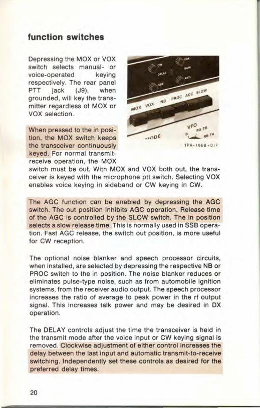
function switches
Depressing the MOX or VOX switch selects manual- or voice-operated keying respectively. The rear panel PTT jack (J9) , when grounded, will key the transmitter regardless of MOX or VOX selection.
When pressed to the In position, the MOX switch keeps the transceiver continuously TPA - 1668 -017
keyed. For normal transmit-receive operation, the MOX switch must be out. With MOX and VOX both out, the transceiver is keyed with the microphone ptt switch. Selecting VOX enables voice keying in sideband or CW keying In CWo
The AGe function can be enabled by depressing the AGe switch. The out position inhibits AGe operation. Release time of the AGe is controlled by the SLOW switch. The In position selects a slow release time. This is normally used in SSB opera~ tion . Fast AGe release, the switch out position, is more useful for CW reception.
The optional noise blanker and speech processor circuits, when installed, are selected by depressing the respective NB or PAOC switch to the In position. The noise blanker reduces or eliminates pulse-type noise, such as from automobile Ignition systems, from the receiver audio output. The speech processor increases the ratio of average to peak power in the rf output signal. This increases talk power and may be desired in OX operation.
The DELAY controls adjust the time the transceiver Is held in the transmit mode after the voice Input or CW keying signal is removed. Clockwise adjustment of either control increases the delay between the last Input and automatic transmlt-to-receive switching. Independently set these controls as desired for the preferred delay times.
20

The GAIN controls adjust the sensitivity to microphone input signals from the operator (VOX) or from the receiver speaker (ANTI-VOX), Set the VOX GAIN so the normal voice level used during transmitting keeps the transceiver keyed. A level too high may cause background noises to key the transmitter while a level too low will require a loud voice input to the microphone for keying. In CW, advance VOX GAIN until an rl output is obtained when the transceiver is keyed in the VOX mode. Set the ANTI-VOX GAIN to the minimum gain (ccw) level that prevents the microphone pickup of the speaker output from tripping the VOX circuit.
The large (rear) BW switch controls the receive bandwidth by selecting any one of the installed filters. Filter installation information " }- Rf
is given in the following maintenance section. The 6-kHz AM filter (AC-3813) is particularly recommended for critical AM listening.
The small (front) PST control
selectivity
positions the passband of TPA-I l;6 6 -017
the selected filter within the 8-kHz passband of the receiver first if and is used to select the desired sideband in receive. For RTTY, position the pointer near LSe (left-most position); and for use, between OPT 2 and OPT 3.
NOTE The MODE switch does not determine which sideband is received. It only selects the desired transmit passband.
The peT control can shift the position of the receive selectivity by adjusting the passband above or below the normal frequency position. In either USB or LSe, rotating the control
21
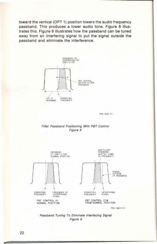
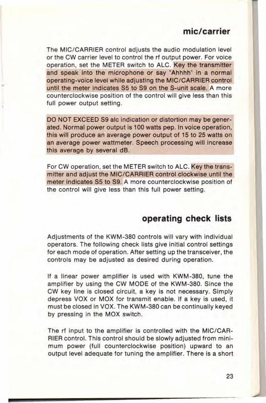
toward the vertical (OPT 1) position lowers the audio frequency passband. This produces a lower audio tone. Figure 8 illustrates this. Figure 9 illustrates how the passband can be tuned away from an interfering signal to put the signal outside the passband and eliminate the interference .
22
"
..... SS8ANO AS ()( TERM INED Bv USB ",LTEII
/
1ST '" ()PEIIATI~ ..... SSB4NO FR{a, .. O.cv
TPA - I66~- OII
Filter Passband Positioning With PBT Control Figure 8
I OP£RATI~ "REQlJENCV
PASStlANO ~ USB FILTE R NORMAL POSITION
/
\ FREOIJE"':Y ~ INTERFEIl ING SIGNAL
PElT CONTROL IN NORMAL POSITION
uSB ",lTER PASseANO SHIFTED DCHiN IN fREQUENCY
SIGNAL OUTSIDE Of' ..... SSBAND
PElT CONTROl.. CCW FROM NORMAL POSITION
Passband Tuning To Eliminate Inter/acing Signal Figure 9
,
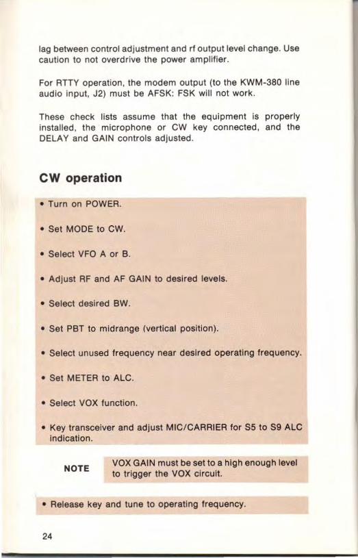
mic/carrier
The MIC/ CARRIER control adjusts the audio modulation level or the CW carrier level to control the rf output power. For voice operation, set the METER switch to ALe . Key the transmitter and speak into the microphone or say 'Ahhhh' in a normal operating-voice level while adjusting the MIG/ CARRIER control until the meter indicates $5 to 59 on the S-unlt scale. A more counterclockwise position of the control will give less than th is full power output setting.
DO NOT EXCEED $9 ale indicat ion or distortion may be generated. Normal power output is 100 watts pep. In voice operation, this will produce an average power output of 15 to 25 watts on an average power wattmeter. Speech processing wi ll increase this average by several dB.
For CW operation, set the METER switch to ALC. Key the trans· mitter and adjust the MIG/ CARRIER control clockwise until the meter ind icates S5 to S9. A more counterclockwise position of the control will give less than th is full power setting.
operating check lists
Adjustments of the KWM·380 controls will vary with individual operators. The following check lists give initial control settings for each mode of operation. After setting up the transceiver , the controls may be adjusted as desired during operation.
If a linear power amplifier is used with KWM·380, tune the amplifier by using the CW MODE of the KWM·380. Since the GW key line is closed circuit, a key is not necessary. Simply depress VOX or MOX for transmit enable. If a key is used, it must be closed in VOX. The KWM·380 can be continually keyed by pressing in the MaX switch.
The rf input to the amplifier is controlled with the MIC/CAR· RIER control. This control should be slowly adjusted from minimum power (full counterclockwise position) upward to an output level adequate for tuning the amplifier. There is a short
23
lag between control adjustment and rf output level change. Use caution to not overdrive the power amplifier.
For RTTY operation, the modem output (to the KWM-380 line audio Input, J2) must be AFSK: FSK will not work.
These check lists assume that the equipment Is properly Installed, the microphone or CW key connected, and the DELAY and GAIN controls adjusted.
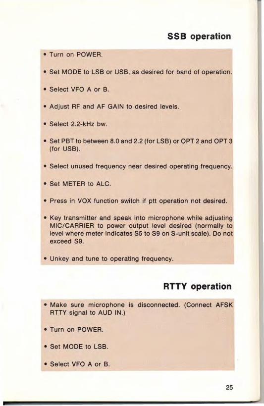
cw operation
• Turn on POWER.
• Set MODE to CW.
• Select VFO A or B.
• Adjust RF and AF GAIN to desired levels.
• Select desired BW.
• Set PBT to midrange (vertical position).
• Select unused frequency near desired operating frequency.
• Set METER to ALC.
• Select VOX function .
• Key transceiver and adjust MIC/CARRIER for S5 to S9 ALC Indication.
NOTE VOX GAIN must be set to a high enough level to trigger the VOX circuit.
• Release key and tune to operating frequency.
24
55B operation
• Turn on POWER.
• Set MODE to LSB or USB, as desired for band of operation.
• Se lect VFO A or B.
• Ad just AF and AF GAIN to desired levels.
• Select 2.2-kHz bw.
• Set PST to between 8.0 and 2.2 (for LSS) or OPT 2 and OPT 3 (for USB).
• Select unused frequency near desired operating frequency.
• Set METER to ALe.
• Press in VOX function switch if ptt operation not desired.
• Key transmitter and speak into microphone while adjusting MIC/ CARRIER to power output level desired (normally to level where meter indicates 55 to 59 on S-unit scale) . Do not exceed 59.
• Unkey and tune to operating frequency.
RTTY operation
• Make sure microphone is disconnected. (Connect AFSK ATTY signal to AUD IN.)
• Turn on POWER.
• Set MODE to lSB.
• Select VFO A or B.
25

• Adjust RF and AF GAIN to desired levels.
• Select desired BW filter for receive. (Transmit function auto· matically selects 2.2·kHz filter.)
• Set PBT to second index mark to leh of top center.
• Set METER to ALC.
• Select unused frequency near desired operating frequency.
• Press in MOX function switch (transceiver keys).
• Adjust MIC/ CARRIER S5 to S9 ALC indication.
• Press MOX function to release to out (un keyed) position. (VOX may be used if AFSK modem mutes tone during receive.)
• Tune to operating frequency.
AM operation (receive only)
• Turn on POWER.
• Set MODE to AM.
• Select VFO A or B.
• Adjust RF and AF GAIN to desired levels.
• Select 8.0 BW. (The operational AC·3813 6·kHz filter Is rec· am mended for optimum am reception.)
• Set peT to vertical position.
• Tune to desired frequency.
26
"
MAINTENANCE
Without extensive test equipment, only a limited amount of maintenance can be performed. The following information guides in determining general functional areas in which a detected malfunction may be located. A multimeter , frequency counter, power meter, dummy load, and rf voltmeter are requ ired for tests.
Detailed test procedures, schematic diagrams, and parts list for the transceiver are contained in the KWM-380 Transceiver Service Manual , Collins publication number 523-0769878. The Service Manual is available through authorized RockwellCollins Amateur Products Distributor/ Service Agencies.
Unless laboratory-type lest equipment is available, it is suggested that any malfunctioning circuit card or subassembly, or the entire transceiver be returned to the Distributor/ Service Agency for testing and repair.
For the names and addresses of authorized Distributor/ Service Agencies write to:
Rockwell·Col lins Customer Service Center P.O. Box 4766 EI Paso, Texas 79914 USA
In any correspondence about the transceiver , give the equip· ment type number and name, Collins 10·digit part number and serial number. This is found on the equipment nameplate located at the bottom center of the rear of the chassis.
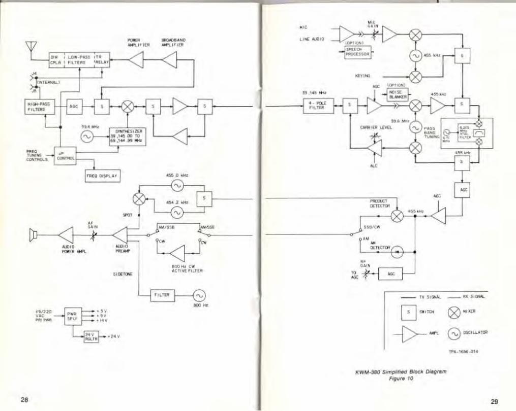
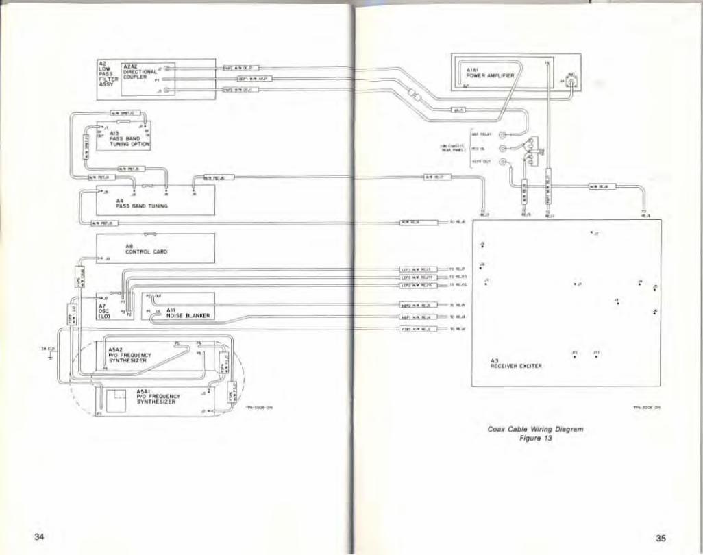
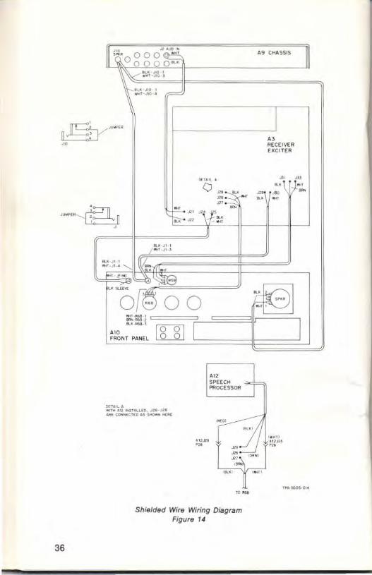
Figures 10 through 14 show a block diagram, circuit card locations, and cable interconnections in the KWM· 380. If cables are removed and replaced, make sure they are reconnected properly and lead dress is restored .
27
r-----------------~------------.
"
... .0'0_'_ ". <ft.. ",,,.. ' .....
""'>0 .. --
-__ " ,[10
_ "1(1 ......... '" ., .... -
'----IIii3C;f- · ·· ·
000 " , . 4OTlI'( "m.
. "
.., .. .... •
" .. -- - - "' .. --8 "''''' @",..
--{>- - G ~,~,.
........ -380 s.m. IT" ~ 8Io<k 0-,;,,.,,, 1;"- '0
"..-' ...... "
"
"
" "
"
•
•
, , , • .. • ,
30
,
0 ,
0 •
•
•
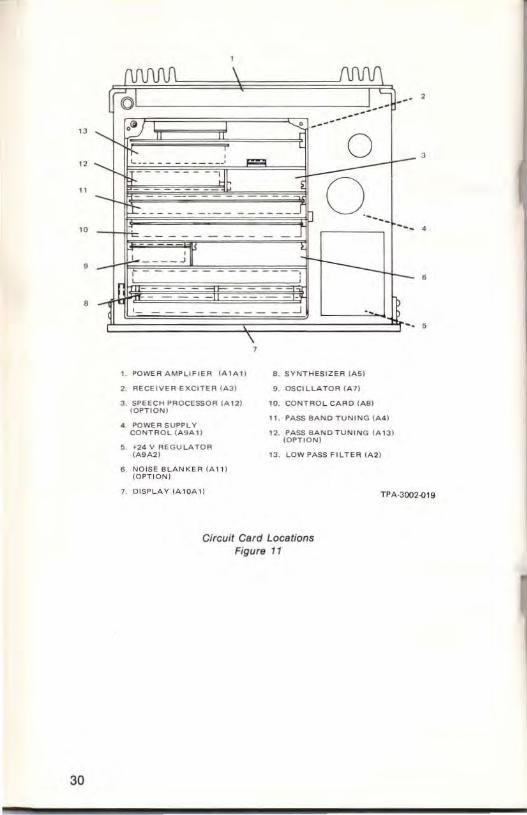
POwE II AMPLIFIE R ( ........ ) .. SYNT H ESIZ E .. , ,.,51
REC EIVER-E KCITER I A 31 .. OSCILLA TOR (A1 )
SPEECH PROCESSO R (AU) ". CONT R O L C A RD ( "'8) (OPTION )
". PASS BAND Tu NIN G (.0,.1 POWE R SUP PLY
CONTRO L ( .0.9.0, I ) " PASS BANDTUN' N O (A13 1 (OPTION)
'2" V RE GU LATOfl ( A 9 .o,2 ) " LOW P ASS FIL TEl, , ..,21
NOISE BLA N KE R ( .0, 11 , (OPTION )
DISPLAY 1.0,10.0,11 TPA.JOOHI19
Circuit Card Locations Figure 11
I ;
. ,
replaceable fuses and la mps
Primary power (located on rear panel) - 8 A, AGC for 100 V; 4 A, AGC for 220 V; -30A, AGC for de operation (under power strapping cover plate).
14-lIolt supply (two fuses located on power supply card under chassis) - 2 A, AGC.
Panel meter lamps (wired into holder at top rear of meter) - T1 3/ 4, 14 V, 100 rnA, type 7373 .
31

... _-
"
:: .. --
., ..
........... OC" ..... '" .. ~ ..
(--'!-"::,~ . ... ~ --~~···~·"·c=,I=" .. ~
, , ,
---===i!r .• ~ .. ...
. , ..... "'" ,.;""
••
.. , '.
- •.
---
. , ,
36
11'~o~gg'~ .. , CHofISSlS II ~' '<i' - ,. .
." JI() , .. ,., .... F
-" I " RECEIVE" E_CITE R
"-,,,< • i( 1,1'::-Q!:,-" '." :: :.~ .,
1"-. " \I~ -t.;:.-• .In ... , .. ...,' ,
I -- t ." •
~" III -...... ........... -. • ,.
~ '00·" 0 0 ;:,: :::.; , , ... _.,
[[]J I "" FIIONT PANEL
O"OIC& .r . ... "",,,,,,. ,ro·'" -= a.ofCnD ., _ .....
.. , .... ~
'" SP'[ECtt PROCESSOR
N •
Shielded Wire Wiring Diagram Figure 14
F-1El - ,
I
receiver-exciter sidetone and spot potentiometer adjustments
Refer to figure 15 for locations of sidetone frequency and level and spot tone level potentiometers. These potentiometers may be adjusted to the level or frequency desired by the operator.
DO NOT MAKE ANY OTHER ADJUSTMENTS ON THE RECEIVER-EXCITER BOARD WITHOUT THE INSTRUCTIONS AND TEST EQUIPMENT SETUP GIVEN IN THE KWM-380 SERVICE MANUAL.
39.6 MHz and 455 kHz oscillator adjustments
The oscillator frequencies are adjustable over a limited range . The oscillators do not normally need adjusting, however the trimmer capacitors are readily accessible if adjustment is required . No test equipment Is necessary.
The test for off-frequency operation and corrective adjustment procedures are as follows:
• Set MODE to USB.
• Set BW to 8.0 and PST to vertical (OPT 1) position.
• Tune WWV at 15.00000 MHz.
• Adjust dial frequency for exact zero-beat of station.
• Note dial frequency offset, If any.
• Repeat operation for 10.00000 MHz and 5.000 00 MHz, noting frequency offset.
• If frequency offset is the same for each frequency, the 455-kHz oscillator needs adJusting. If offsets differ, the 39.6-MHz oscillator needs adjusting.
• To adjust either osci llator, tune WWV at 15.00000 MHz. Set dial frequency to 15.00000 MHz. Adjust the appropriate oscillator trimmer capacitor for zero-beat. (Refer to figure 16 for capacitor access hole location.)
37

• Recheck frequency offsets, as above. If both oscillators are off frequency, these steps may have to be repeated several times.
38
EXCITEA RF OUT
"
R921 SIOETONE FREO
1ST MIX INJECT
"
Jl0 Jl1 45S 454.2 kHz kHz
39.6 MHz
"
RS1S SIDETONE l Vl
Receiver-exciter Connector and Ad/us tments Locations Figure 15
NOISE BLANKER JUMPER
R61S SPOT TONE lVl
TPA·1683.(11 9

,
455 kHz asc TR IMMER CAP ACCESS HOLE
LEFT SIDE V IEW
39.6 MHz esc TRIMMER CAP ACCESS HOLE
o 0
Oscillator Trimmer Capacitor Adiustment Hole Location Figura 16
general troubleshooting
de vollages
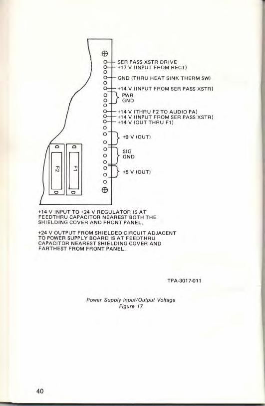
Figure 17 shows the power supply input and output voltages. These shou ld be checked along with other checks for any malfunction. Other than fuse replacement, repair should not be attempted without information in the Service Manual.
39
Gl SER PASS XSTR DRIVE +17 V (INPUT FROM RECTI
GNO lTHRU HEAT SINK TH ERM SW)
+1 4 V (INPUT FROM SEA PASS XSTR) PWA GND
+14 V (THRU F2 TO AUDIO PAl +1 4 V (INPUT FROM SEA PASS XSTR) + 14 V (OUTTHRU F1)
iii V (oun 0 0 D SOG
G G a GND a a
+5 v (OUT) a a Gl 0
+14 V INPUT TO +24 V REGULATOR IS AT FEEDTHRU CAPACITOR NEAREST BOTH THE SHIELDING COVER AND FRONT PANEl.
+24 V OUTPUT FROM SHIELDED CIRCUIT ADJACENT TO POWER SUPPLY BOARD IS AT FEEOTHAU CAPACITOR NEARESTSHIELOING COVER AND FARTHEST FROM fRONT PANEL.
40
TPA-301].()l'
Power Supply Input/Output Voltage Figure 17

oscillator (fixed-frequencies) and synthesizer (variable-frequency) outputs
Refer to figure 15 for oscillator and synthesizer signal connec· tor locations on the receiver·exciter board. Make the following measurements with an rf voltmeter and frequency counter . If the fixed-frequency signals are not correct, the oscillator is malfunctioning. If the variable-frequency signal is not correct, the synthesizer or control card is malfunctioning. Refer to the Service Manual or contact a Distributor/Service Agency for repair.
39.60000 MHz (J3) in receive or transmit - approx 0.5 V rms across 50 n
455 kHz (J10) in SSB receive - greater than 50 mV rms across 50 n
454.2 kHz (J11) in CW receive - greater than 50 mV rms across 50 n
1st mixer injection (J2) in receive or transmit; 39.145 MHz for 00.00000 MHz dial frequency thru 69.144 99 MHz for 29.999 99 MHz dial frequency - approx 0.5 V rms across 50 n
Rap id beeping in the speaker indicates the synthesizer is unlocked. This may be caused either by a faulty 5·, 9·, or 24·V power supply output , or by a malfunction in the synthesizer. Check the power supply outputs first, then check the coax cable between the synthesizer and oscillator. Check the oscilla· tor and synthesizer output levels for values indicated above. If all these are correct, the synthesizer is malfunctioning.
receiverllow pass filter
If there is no audio output, check F1 , F2, and the + 14·V outputs at the power supply. If these are not faulty, check the oscillator and synthesizer outputs. If these are not faulty, the receiver circuits are malfunctioning. Refer to the Service Manual or con· tact a Distributor/ Service Agency for repair.
41
If the audio output is weaker than expected for a known input signal , connect the antenna to the ReV IN jack on the transceiver rear panel (to bypass the low-pass filter). If the audio output becomes normal, the low-pass filter or control card is malfunctioning. If the output remains weak, the receiver circuits are malfunctioning. Refer to the Service Manual or contact a Distributor/ Service Agency for repair.
exciter
Refer to figure 15 for the exciter rf output connector on the receiver-exciter board. Disconnect cable from J1. Set the MODE to CW, MIC/CARRIER to full maximum (clockwise position) , and depress MOX. Measure the exciter output (at J1) with an rf voltmeter and frequency counter. The level should be approximately 3 V rms across 50 n and the frequency the same as the dial frequency. If the output is not correct, refer to the Service Manual or contact a Distributor/Service Agency for repair. (Switch off MOX and reconnect cable at J1 when test is complete.)
power amplifierllow pass filter
Connect an rf power meter and dummy load to the transceiver rf connector. Set the MODE to CW and MIC/CARRIER to full maximum (clockwise position). In measuring rf power in the following steps note that, unless the AC-2BOB Blower Kit is installed, the output will decrease to about half power within 30 seconds after the MaX switch is turned on. Read the power meter before the power decrease.
Measure the power amplifier output by tuning to a valid transmit frequency, switching on MaX, measuring the power, then switching off MaX. Make a power measurement in each of the bands. If the output power is less than approximately 100 watts in all of the bands, the malfunction is probably in the power amplifier. If one or more of the bands show full output power, the malfunction is probably in the low-pass filter or control card . Refer to the Service Manual or contact a Distributor/ Service Agency for repair.
42

,
bandwidlh (cryslal) filler inslallalion
The AC-381 0 through AC-3813 Filter Kits may be installed individually or as a group to provide additional bandwidth selectivity in the KWM-380. Except for the AC-3813 (AM Filter) , the filters may be installed in any of the positions on the Pass Band Tuning or Pass Band Tuning Option card. Figures 18 and 19, and table 2 show the positions and list the BW SELECTIVITY switch position that enables the filter installed in that associated position. For operating convenience, it is suggested that the filters be installed in order of decreasing bandwidth.
To install a filter , remove the appropriate circuit card , place mica washers (supplied with the filter kit) on the filter terminals, then position the filter on the circuit card. Secure the filter with the supplied flat washers , lockwashers, and hexnuts (also sup· plied with the kit). Solder the filter terminals to the circuit pads on the card .
Before installing the AC·3813 AM Filter, the existing piggy·back circu it board filter must be removed from the Pass Band Tun· ing card . Remove the mounting hardware from the board and unsolder the pins from the circuit pads on the card. Mount the AM filter as described for the other 'ilters.
~§
B ° ° W
~ <C. 31103 6 0 . ~,
AM fI~H" •• C IACUor C.AO
° '" , H. ".NO • • O ° ".",-"AI
1° O""<llT(A
°1
Pass Band Tuning Card Filter Locations Figure 18
I" ";1
"
B
43

44
(), R" _OOT " ~"_ I N(),
10 Of'TJ "LTE"
01
10 on, ''In"
01 . " C'RCU " C.AO
".-""-Q,.
Pass Band Tuning Option Card Filter Locations Figura 19
Table 2. BW SELECTIVITY Switch and Filtar Position Relationships.
BW SELECTIVITY FILTER POSITION SWITCH POSITION ON CIRCUIT CARD
8.0 A4 card upper position 22 A4 card middle position OPT 1 A13 card lower position OPT 2 A4 card lower posit ion OPT 3 A13 card upper position
ACCESSORIES
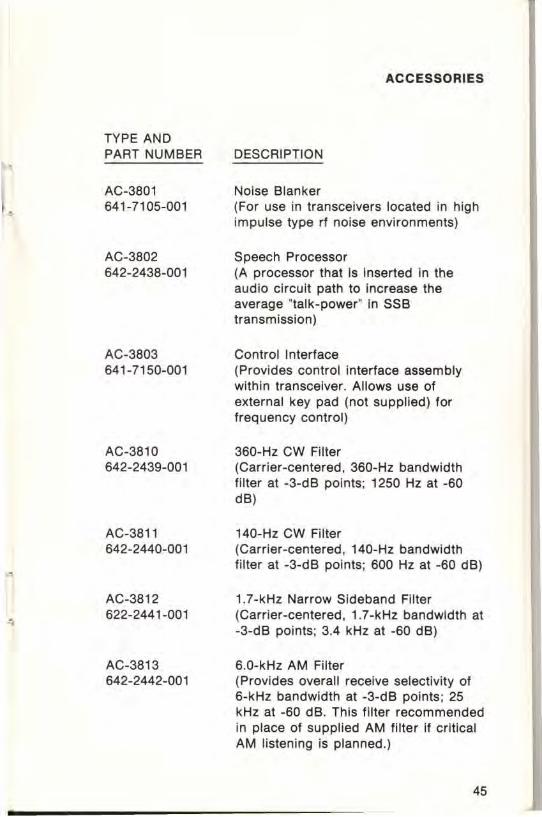
TYPE AND PART NUMBER DESCRIPTION ,
AC-3801 Noise Blanker 641-7105-001 (For use in transceivers located in high
-- impulse type rf noise environments)
AC-3802 Speech Processor 642-2438-001 (A processor that is inserted in the
audio circuit path to Increase the average ' talk-power' in SSB transmission)
AC-3803 Control Interface 641-7150-001 (Provides control interface assembly
within transceiver. Allows use of external key pad (not supplied) for frequency control)
AC-3810 360-Hz CW Filter 642-2439-001 (Carrier-centered, 360-Hz bandwidth
filter at -3-dB points; 1250 Hz at -60 dB)
AC-3811 140-Hz CW Filter 642-2440-001 (Carrier-centered, 140-Hz bandwidth
filter at -3-dB points; 600 Hz at -60 dB) "
AC-3812 1.7-kHz Narrow Sideband Filter
• 622-2441-001 (Carrier-centered , 1.7-kHz bandwidth at -3-d8 points; 3.4 kHz at -60 dB)
AC-3813 6.0-kHz AM Filter 642-2442-001 (Provides overall receive selectivity of
6-kHz bandwidth at -3-d8 pOints ; 25 kHz at -60 dB. This filter recommended in place of supplied AM filter if critical AM listening is planned.)
45

TYPE AND PART NUMBER
AC-2801 622-3537-001
AC-2808 622-3547-001
AC-2821 622-3564-001
MM-280 020-0260-010
MM-281 020-0260-020
SM-280 020-0261-010
SM-281 020-0261-020
46
DESCRIPTION
Rack Mount (Used for mounting transceiver in standard 19-in racks or cabinets)
Blower Kit (Used to enable operation at continuous 100-watt power output; ac power from transceiver. Recommended for RTTY operation. Not usually needed for voice or cw.)
DC Standby Power Cable (2-metre (6.5-foot) dc power cable for use with transceiver for emergency operation from 12-V battery; includes radio power connector , battery clamps, .:md installation instructions)
Microphone, Handheld (Handheld dynamic omnidirectional microphone with low impedance; has push-to-talk switch; color, black)
Microphone, Handheld (Handheld dynamic microphone with low impedance and noise-cancelling characteristics; has push-to-talk switch; color, black)
Microphone, Desktop (Desktop dynamic microphone with low impedance and cardioid sound pattern; has push-to-talk bar; color, black)
Microphone, Desktop (Desktop dynamiC microphone with low impedance and noise-cancelling characteristic; has push-to-talk bar plus continuous-key switch; color, black)

TYPE AND PART NUMBER
AC-2827 634-8545-001
AC-2828 634-8546-001
AC-2829 622-3571-001
AC-2830 622-3572-001
DESCRIPTION
Key, CW (Hand-operated CW key)
Microphone Foot Switch (Foot switch for hands-free keying of microphone)
Headphones, Standard (Standard headphones with 600-ohm impedance; has sound-blocking earmuffs)
Headphones (Lightweight headphones with SOO-ohm impedance; has comfort-designed earpieces)
47/48

AMATEUR EQUIPMENT LIMITED WARRANTY
Rockwell-Collins agrees to repair or replace, without charge and within a reasonable period, any equipment, parts, or accessories which are defective as to design, workmanship or material and which are returned to Rockwell-Collins at its factory, or its designated Service Agency, transportation prepaid, provided:
(a) Buyer presents a properly executed Warranty Verification Certificate.
(b) Notice of the claimed defect is given Rockwell-Collins or an authorized Service Agency, or authorized Distributor. in writing, within 1 year from the date of purchase and goods are returned in accordance with Rockwell-Collins instructions.
(c) Any failure due to use of equipment for purposes other than those contemplated in normal amateur operations or In violation of Rockwell-Collins applicable Instruction Book shall not be deemed a defect within the meaning of these provisions.
This Warranty is void with respect to equlpmenl which Is altered. modified or repaired by other than Rockwell -Cotllns or a Rockwell-Coll ins Authorized Service Agency. However, alternation or modification in accordance with Rockwell-Collins Service Bulletins shall not aHect this Warranty.
The foregoing shall constitute the Buyer's sole right and remedy under this guarantee. IN NO EVENT SHALL ROCKWELL-COLLINS HAVE ANY LIABILITY FOR INCIDENTAL OR CONSEQUENTIAL DAMAGES, OR FOR LOSS, DAMAGE OR EXPENSE DIRECTLY OR INDIRECTLY ARISING FROM THE USE OF THE PRODUCTS, OR ANY INABILITY TO USE THEM EITHER SEPARATELY OR IN COMBINATION WITH OTHER EQUIPMENT OR MATERIALS OR FROM ANY OTHER CAUSE. (Some states do not allow limitations on how long an Implied warranty lasts or the exclusion or limitation of incidental or consequential damages, so the above limitations or exclusions may not apply to you.)
This Warranty gives you specific legal rights, and you may also have other rights which vary from state to state.
IMPORTANT: The Amateur Equipment Warranty Verification Certificate must be completed by seller on date of delivery of new equipment.
Unauthorized modification to the equipment voids this warranty.
Collins Telecommunications Products Division · RockwelllntefOational Cedar Rapids, Iowa 52.06

523-01&N11_002211
s
Rockwell International
Collin. Telecommunication. Product. Dlvi.lon
Electronic Systems Group
l()'SO P,in!.o In U.S.A.