collaborative harq schemes for cooperative diversity
TRANSCRIPT

Collaborative HARQ Schemes for Cooperative Diversity
Communications in Wireless Networks
Kun Pang
A thesis submitted in fulfillment of therequirements for the degree of Master of Philosophy (Research)
School of Electrical & Information EngineeringThe University of Sydney
February 2008

To my family
ii

Abstract
Wireless technology is experiencing spectacular developments, due to the emergence of in-
teractive and digital multimedia applications as well as rapid advances in the highly inte-
grated systems. For the next-generation mobile communication systems, one can expect
wireless connectivity between any devices at any time and anywhere with a range of mul-
timedia contents. A key requirement in such systems is the availability of high-speed and
robust communication links. Unfortunately, communications over wireless channels inher-
ently suffer from a number of fundamental physical limitations, such as multipath fading,
scarce radio spectrum, and limited battery power supply for mobile devices.
Cooperative diversity (CD) technology is a promising solution for future wireless communi-
cation systems to achieve broader coverage and to mitigate wireless channels’ impairments
without the need to use high power at the transmitter. In general, cooperative relaying sys-
tems have a source node multicasting a message to a number of cooperative relays, which
in turn resend a processed version message to an intended destination node. The destination
node combines the signal received from the relays, and takes into account the source’s origi-
nal signal to decode the message. The CD communication systems exploit two fundamental
features of the wireless medium: its broadcast nature and its ability to achieve diversity
through independent channels.
A variety of relaying protocols have been considered and utilized in cooperative wireless
networks. Amplify and forward (AAF) and decode and forward (DAF) are two popular
protocols, frequently used in the cooperative systems. In the AAF mode, the relay amplifies
the received signal prior to retransmission. In the DAF mode, the relay fully decodes the
received signal, re-encodes and forwards it to the destination. Due to the retransmission
without decoding, AAF has the shortcoming that noise accumulated in the received signal
is amplified at the transmission. DAF suffers from decoding errors that can lead to severe
iii

error propagation. To further enhance the quality of service (QoS) of CD communication
systems, hybrid Automatic Repeat-reQuest (HARQ) protocols have been proposed. Thus, if
the destination requires an ARQ retransmission, it could come from one of relays rather than
the source node.
This thesis proposes an improved HARQ scheme with an adaptive relaying protocol (ARP).
Focusing on the HARQ as a central theme, we start by introducing the concept of ARP.
Then we use it as the basis for designing three types of HARQ schemes, denoted by HARQ
I-ARP, HARQ II-ARP and HARQ III-ARP. We describe the relaying protocols, (both AAF
and DAF), and their operations, including channel access between the source and relay, the
feedback scheme, and the combining methods at the receivers.
To investigate the benefits of the proposed HARQ scheme, we analyze its frame error rate
(FER) and throughput performance over a quasi-static fading channel. We can compare
these with the reference methods, HARQ with AAF (HARQ-AAF) and HARQ with perfect
distributed turbo codes (DTC), for which correct decoding is always assumed at the relay
(HARQ-perfect DTC). It is shown that the proposed HARQ-ARP scheme can always per-
forms better than the HARQ-AAF scheme. As the signal-to-noise ratio (SNR) of the chan-
nel between the source and relay increases, the performance of the proposed HARQ-ARP
scheme approaches that of the HARQ-perfect DTC scheme.
iv

Acknowledgements
This thesis concludes two years’ study at the University of Sydney. More importantly, it
marks the end of another chapter in my life, the invaluable experience of living in Australia
and being part of its colorful culture.
I would like to thank my supervisor, Professor Branka Vucetic, for providing me with this
treasured opportunity of being a member of the Telecommunication Laboratory and bring-
ing my academic perspective to a new level. With great perception, she defined the early
directions of my research, and has continuously provided generous support along the way. I
am very grateful to her for giving me lots of precious chances to study with many intelligent
students at the University of Sydney. In the weekly meetings for my research and tutorials,
her professionalism, accurate advice, suggestions and her ways of thinking inspired me, and
this inspiration guides me in every moment of my life.
I also wish to express gratitude to Dr Yonghui Li, who acted as my associate supervisor
during my Master degree studies. He deserves credit for his valuable instruction, suggestions
and technical advice any time that I called on him.
Throughout my overseas studies, there was one person, Dr Willem Labuschagne, who un-
conditionally stood by me, helping and giving me countless advice regarding academic and
personal problems before, during and after my studies at the University of Otago, New
Zealand, with a respectful attitude towards my often naive scientific remarks, thus boosting
my self-confidence. I must not forget his invaluable help for my research proposal during
my application time to the University of Sydney.
More than seven years ago, my father’s friend, Dr Zhifa Sun, visited Tianjin. It was he who
suggested that my father support me in pursuit of further overseas studies. He was always
v

there for me during the past seven years, with his precise guidance, patience and immediate
help.
There is a special family that I will always think of when implementing my proposed scheme
with programs. Iain Hewson, thank you for the precious time when we were discussing
the programming and debugging skills in your office, which helped me establish a solid
fundamental basis for the programming and let me smoothly finish my Master’s studies at
the University of Sydney. Thank you for accepting me as your family member when I stayed
in New Zealand, I had a great time with the babies; now they are boys, and I missed the
wonderful time when we were together.
How could I forget the numerous people that enriched my life in the lab? Kumudu Munas-
inghe, Srdjan Vukadinovic, Esshan Sakhaee, Wibowo Hardjawana, Rui Li, Kingsley Allan,
Lixiang Xiong, Huabing Liu, Zhuo Chen, Zhanjiang Chi, Yang Tang, Zhendong Zhou, Xi-
aoyuan Ta, Ting Sun, Leilei Wu. Their support and cooperation helped me run the social
activities very successfully during the past two years.
I want to thank Wesley Wu and Michael Zhou from ITU, Ping Zhang and Christine Green
from the School’s Resource Office, for their diligence and enthusiasm in giving me help with
my research and teaching during the past two academic years.
I am grateful to Ms. Pat Skinner who has helped a lot in improving the presentation of this
thesis by providing a professional proofreading services.
Special thanks to a wonderful couple, Dr Xueyue Zhang and Qi Li, my neighbors since I
was born, for all the love they have given me. I couldn’t believe we had another chance to
see each other after they immigrated to Australia. Thanks for their warm help since I came
to Sydney.
The last, and definitely not the least, for my family, my father Professor Jinzhao Pang, mother
Tongbin Guo, there are no words or acts that I can provide to describe or return their love
and support. Their encouragement and inspiration are enormous sources of energy for me.
It is their tolerance and love that carry me through the peaks and troughs of my entire life.
Definitely, one day, I hope we can live together again instead of living on different sides of
Pacific Ocean, as should be. I love you the most.
vi

Statement of Originality
All material presented in this thesis is the original work of the author, unless otherwise
stated. The content of this thesis has not been previously submitted for examination as part
of any academic qualifications. Most of the results contained herein have been submitted for
publication, in journals or conferences of international standing. The author’s contribution
in terms of published material is listed in the next section, “Publications”.
The original motivation to pursue research in this field was provided by my thesis supervi-
sors, Professor Branka Vucetic and Dr Yonghui Li in the School of Electrical and Information
Engineering, the University of Sydney, Australia.
Kun Pang
Telecommunication Laboratory
School of of Electrical and Information Engineering
The University of Sydney
New South Wales, Australia
February 2008
vii

Publications
Journal Paper
[J1] K. Pang, Y.H. Li and B. Vucetic “ An improved HARQ scheme for cooperative diver-
sity communication in wireless networks,” IEEE Transactions on Vehicular Technol-
ogy (IEEE Trans. Veh. Technol). To be submitted for publication.
Conference Paper
[C1] K. Pang, Y.H. Li and B. Vucetic “An improved hybrid ARQ scheme in cooperative
wireless networks,” IEEE Vehicular Technology Conference (IEEE VTC’08), Calgary,
Canada, Sep. 2008. Accepted for publication.
viii
Contents
Preface ii
Abstract iii
Acknowledgements v
Statement of Originality vii
Publications viii
TABLE OF CONTENTS viii
LIST OF FIGURES xii
LIST OF TABLES xv
LIST OF ACRONYMS xvi
1 Introduction 11.1 Background . . . . . . . . . . . . . . . . . . . . . . . . . . . . . . . . . . 1
1.2 Research Problems and Methodology . . . . . . . . . . . . . . . . . . . . 5
1.3 Thesis Outline . . . . . . . . . . . . . . . . . . . . . . . . . . . . . . . . . 7
2 Background 82.1 Digital Communication Systems . . . . . . . . . . . . . . . . . . . . . . . 8
2.2 Fading Channels . . . . . . . . . . . . . . . . . . . . . . . . . . . . . . . 10
2.2.1 Statistical Models for Fading Channels . . . . . . . . . . . . . . . 10
2.2.1.1 Rayleigh Fading . . . . . . . . . . . . . . . . . . . . . . 11
2.2.1.2 Rician Fading . . . . . . . . . . . . . . . . . . . . . . . 11
ix

2.2.2 Slow and Fast Fading . . . . . . . . . . . . . . . . . . . . . . . . . 12
2.3 Error Control Scheme - Forward Error Correction . . . . . . . . . . . . . . 12
2.3.1 Cyclic Redundancy Check Codes . . . . . . . . . . . . . . . . . . 13
2.3.2 Convolutional Codes . . . . . . . . . . . . . . . . . . . . . . . . . 15
2.3.3 Maximum Likelihood Decoding . . . . . . . . . . . . . . . . . . . 16
2.3.4 Viterbi Algorithm . . . . . . . . . . . . . . . . . . . . . . . . . . . 17
2.3.5 Turbo Codes . . . . . . . . . . . . . . . . . . . . . . . . . . . . . 18
2.3.6 Soft Output Viterbi Algorithm . . . . . . . . . . . . . . . . . . . . 19
2.3.7 Iterative SOVA Decoding of Turbo Codes . . . . . . . . . . . . . . 21
2.4 Error Control Scheme - Automatic Repeat Request . . . . . . . . . . . . . 23
2.4.1 Stop-and-wait ARQ . . . . . . . . . . . . . . . . . . . . . . . . . 23
2.4.2 Go-back-N ARQ . . . . . . . . . . . . . . . . . . . . . . . . . . . 24
2.4.3 Selective-repeat ARQ . . . . . . . . . . . . . . . . . . . . . . . . 25
2.5 Error Control Scheme - Hybrid Automatic Repeat Request . . . . . . . . . 25
2.5.1 Type-I HARQ Scheme . . . . . . . . . . . . . . . . . . . . . . . . 26
2.5.1.1 Pure Type-I HARQ Scheme . . . . . . . . . . . . . . . . 27
2.5.1.2 Type-I HARQ Scheme with Chase Combining . . . . . . 27
2.5.2 Type-II HARQ Scheme . . . . . . . . . . . . . . . . . . . . . . . . 27
2.5.3 Type-III HARQ Scheme . . . . . . . . . . . . . . . . . . . . . . . 29
3 Introduction to Cooperative Diversity 313.1 Introduction . . . . . . . . . . . . . . . . . . . . . . . . . . . . . . . . . . 32
3.1.1 Multiple-input Multiple-output Technique . . . . . . . . . . . . . . 32
3.1.2 Cooperative Diversity Technique . . . . . . . . . . . . . . . . . . . 33
3.2 Cooperative Diversity Protocols . . . . . . . . . . . . . . . . . . . . . . . 34
3.2.1 Fixed Relaying Protocols . . . . . . . . . . . . . . . . . . . . . . . 34
3.2.1.1 Amplify and Forward . . . . . . . . . . . . . . . . . . . 35
3.2.1.2 Decode and Forward . . . . . . . . . . . . . . . . . . . . 36
3.2.2 Selection Relaying Protocol . . . . . . . . . . . . . . . . . . . . . 36
3.2.3 Incremental Relaying Protocol . . . . . . . . . . . . . . . . . . . . 37
3.3 Coded Cooperation Schemes . . . . . . . . . . . . . . . . . . . . . . . . . 38
3.3.1 Distributed Rate Compatible Convolutional Codes . . . . . . . . . 38
3.3.2 Distributed Turbo Codes . . . . . . . . . . . . . . . . . . . . . . . 39
4 Collaborative HARQ Schemes in Wireless Networks 41
x

4.1 Introduction . . . . . . . . . . . . . . . . . . . . . . . . . . . . . . . . . . 41
4.2 System Model . . . . . . . . . . . . . . . . . . . . . . . . . . . . . . . . . 43
4.3 Collaborative HARQ with the ARP Scheme . . . . . . . . . . . . . . . . . 46
4.3.1 Type I HARQ with the ARP Scheme . . . . . . . . . . . . . . . . 47
4.3.2 Type II HARQ with the ARP Scheme . . . . . . . . . . . . . . . . 50
4.3.3 Type III HARQ with the ARP Scheme . . . . . . . . . . . . . . . . 51
4.4 Simulation Results . . . . . . . . . . . . . . . . . . . . . . . . . . . . . . 53
4.5 Conclusion . . . . . . . . . . . . . . . . . . . . . . . . . . . . . . . . . . 58
5 Performance Analysis of Collaborative HARQ Schemes in Wireless Networks 595.1 WEPs of the Relaying Protocols in the HARQ I Schemes . . . . . . . . . . 59
5.1.1 WEP of HARQ I-AAF . . . . . . . . . . . . . . . . . . . . . . . . 60
5.1.2 WEP of HARQ I-perfect DTC . . . . . . . . . . . . . . . . . . . . 62
5.1.3 WEP of HARQ I-ARP . . . . . . . . . . . . . . . . . . . . . . . . 63
5.2 WEPs of the Relaying Protocols in the HARQ II Schemes . . . . . . . . . 66
5.2.1 WEP of HARQ II-AAF . . . . . . . . . . . . . . . . . . . . . . . 66
5.2.2 WEP of HARQ II-perfect DTC . . . . . . . . . . . . . . . . . . . 67
5.2.3 WEP of HARQ II-ARP . . . . . . . . . . . . . . . . . . . . . . . . 68
5.3 WEPs of the Relaying Protocols in the HARQ III Schemes . . . . . . . . . 69
5.3.1 WEP of HARQ III-AAF . . . . . . . . . . . . . . . . . . . . . . . 69
5.3.2 WEP of HARQ III-perfect DTC . . . . . . . . . . . . . . . . . . . 70
5.3.3 WEP of HARQ III-ARP . . . . . . . . . . . . . . . . . . . . . . . 70
5.4 Throughput Analysis . . . . . . . . . . . . . . . . . . . . . . . . . . . . . 71
5.5 Performance Comparison between HARQ-ARP and HARQ-perfect DTC . 74
5.6 Performance Comparison between HARQ-ARP and HARQ-AAF . . . . . 76
5.7 Simulation Results . . . . . . . . . . . . . . . . . . . . . . . . . . . . . . 79
5.8 Conclusion . . . . . . . . . . . . . . . . . . . . . . . . . . . . . . . . . . 86
6 Conclusions 876.1 Future Work . . . . . . . . . . . . . . . . . . . . . . . . . . . . . . . . . . 88
A The Derivation of Eq. (5.18) 90
B Proof of Inequality (5.54) 93
xi

List of Figures
1.1 The relay channel . . . . . . . . . . . . . . . . . . . . . . . . . . . . . . . 4
2.1 Block diagram of a typical digital communication system . . . . . . . . . . 9
2.2 A (2,1,2) convolutional encoder . . . . . . . . . . . . . . . . . . . . . . . 15
2.3 A rate 1/3 turbo encoder . . . . . . . . . . . . . . . . . . . . . . . . . . . 19
2.4 An iterative turbo code decoder based on the SOVA algorithm . . . . . . . 22
2.5 Stop-and-wait ARQ . . . . . . . . . . . . . . . . . . . . . . . . . . . . . . 23
2.6 Go-back-N ARQ with N = 7 . . . . . . . . . . . . . . . . . . . . . . . . . 24
2.7 Selective-repeat ARQ . . . . . . . . . . . . . . . . . . . . . . . . . . . . . 25
2.8 Type-II HARQ scheme . . . . . . . . . . . . . . . . . . . . . . . . . . . . 28
2.9 An example of an RCPC-ARQ system . . . . . . . . . . . . . . . . . . . . 29
3.1 MIMO wireless link . . . . . . . . . . . . . . . . . . . . . . . . . . . . . . 33
3.2 A model of a cooperative communication technique . . . . . . . . . . . . . 34
3.3 Block diagram of the distributed rate compatible puncture convolutional codes 39
3.4 Block diagram of the distributed turbo coding technique . . . . . . . . . . 40
4.1 The proposed HARQ scheme with ARP where the relay uses either AAF or
DAF . . . . . . . . . . . . . . . . . . . . . . . . . . . . . . . . . . . . . . 48
4.2 Simulation conditions . . . . . . . . . . . . . . . . . . . . . . . . . . . . . 54
4.3 FER comparison of HARQ I-AAF, HARQ I-DAF and HARQ I-ARP schemes
in a quasi-static fading channel with SNR 0-8 dB of the inter-user channel . 55
4.4 FER comparison of HARQ II-AAF, HARQ II-DAF and HARQ II-ARP schemes
in a quasi-static fading channel with SNR 0-8 dB of the inter-user channel;
the puncturing rates for the first transmission are 4/5 . . . . . . . . . . . . . 56
xii
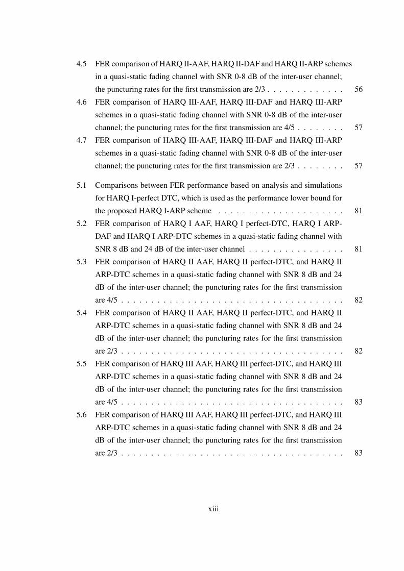
4.5 FER comparison of HARQ II-AAF, HARQ II-DAF and HARQ II-ARP schemes
in a quasi-static fading channel with SNR 0-8 dB of the inter-user channel;
the puncturing rates for the first transmission are 2/3 . . . . . . . . . . . . . 56
4.6 FER comparison of HARQ III-AAF, HARQ III-DAF and HARQ III-ARP
schemes in a quasi-static fading channel with SNR 0-8 dB of the inter-user
channel; the puncturing rates for the first transmission are 4/5 . . . . . . . . 57
4.7 FER comparison of HARQ III-AAF, HARQ III-DAF and HARQ III-ARP
schemes in a quasi-static fading channel with SNR 0-8 dB of the inter-user
channel; the puncturing rates for the first transmission are 2/3 . . . . . . . . 57
5.1 Comparisons between FER performance based on analysis and simulations
for HARQ I-perfect DTC, which is used as the performance lower bound for
the proposed HARQ I-ARP scheme . . . . . . . . . . . . . . . . . . . . . 81
5.2 FER comparison of HARQ I AAF, HARQ I perfect-DTC, HARQ I ARP-
DAF and HARQ I ARP-DTC schemes in a quasi-static fading channel with
SNR 8 dB and 24 dB of the inter-user channel . . . . . . . . . . . . . . . . 81
5.3 FER comparison of HARQ II AAF, HARQ II perfect-DTC, and HARQ II
ARP-DTC schemes in a quasi-static fading channel with SNR 8 dB and 24
dB of the inter-user channel; the puncturing rates for the first transmission
are 4/5 . . . . . . . . . . . . . . . . . . . . . . . . . . . . . . . . . . . . . 82
5.4 FER comparison of HARQ II AAF, HARQ II perfect-DTC, and HARQ II
ARP-DTC schemes in a quasi-static fading channel with SNR 8 dB and 24
dB of the inter-user channel; the puncturing rates for the first transmission
are 2/3 . . . . . . . . . . . . . . . . . . . . . . . . . . . . . . . . . . . . . 82
5.5 FER comparison of HARQ III AAF, HARQ III perfect-DTC, and HARQ III
ARP-DTC schemes in a quasi-static fading channel with SNR 8 dB and 24
dB of the inter-user channel; the puncturing rates for the first transmission
are 4/5 . . . . . . . . . . . . . . . . . . . . . . . . . . . . . . . . . . . . . 83
5.6 FER comparison of HARQ III AAF, HARQ III perfect-DTC, and HARQ III
ARP-DTC schemes in a quasi-static fading channel with SNR 8 dB and 24
dB of the inter-user channel; the puncturing rates for the first transmission
are 2/3 . . . . . . . . . . . . . . . . . . . . . . . . . . . . . . . . . . . . . 83
xiii

5.7 Throughput comparison of HARQ I AAF, HARQ I perfect-DTC, HARQ I
ARP-DAF and HARQ I ARP-DTC schemes in a quasi-static fading channel
with SNR 8 dB of the inter-user channel . . . . . . . . . . . . . . . . . . . 84
5.8 Throughput comparison of HARQ I AAF, HARQ I perfect-DTC, HARQ I
ARP-DAF and HARQ I ARP-DTC schemes in a quasi-static fading channel
with SNR 24 dB of the inter-user channel . . . . . . . . . . . . . . . . . . 84
5.9 Throughput comparison of HARQ II AAF, HARQ II perfect-DTC, and HARQ
II ARP-DTC schemes in a quasi-static fading channel with SNR 8 dB and 24
dB of the inter-user channel; the puncturing rates for the first transmission
are 4/5 . . . . . . . . . . . . . . . . . . . . . . . . . . . . . . . . . . . . . 85
5.10 Throughput comparison of HARQ III AAF, HARQ III perfect-DTC, and
HARQ III ARP-DTC schemes in a quasi-static fading channel with SNR
8 dB and 24 dB of the inter-user channel; the puncturing rates for the first
transmission are 4/5 . . . . . . . . . . . . . . . . . . . . . . . . . . . . . . 85
5.11 Throughput comparison of HARQ ARP schemes in a quasi-static fading
channel with SNR 24 dB of the inter-user channel; the puncturing rates for
the first transmission are 4/5 . . . . . . . . . . . . . . . . . . . . . . . . . 86
xiv

List of Tables
4.1 Puncturing table for direct channel in a HARQ II-ARP scheme with a rate
4/5 code . . . . . . . . . . . . . . . . . . . . . . . . . . . . . . . . . . . . 50
4.2 Puncturing table for relay channel in a HARQ II-ARP scheme with a rate 4/5
code . . . . . . . . . . . . . . . . . . . . . . . . . . . . . . . . . . . . . . 51
4.3 Puncturing table for direct channel in a HARQ II-ARP scheme with a rate
2/3 code . . . . . . . . . . . . . . . . . . . . . . . . . . . . . . . . . . . . 51
4.4 Puncturing table for relay channel in a HARQ II-ARP scheme with a rate 2/3
code . . . . . . . . . . . . . . . . . . . . . . . . . . . . . . . . . . . . . . 51
4.5 Puncturing table for direct channel in a HARQ III-ARP scheme with a rate
4/5 code . . . . . . . . . . . . . . . . . . . . . . . . . . . . . . . . . . . . 52
4.6 Puncturing table for relay channel in a HARQ III-ARP scheme with a rate
4/5 code . . . . . . . . . . . . . . . . . . . . . . . . . . . . . . . . . . . . 52
4.7 Puncturing table for direct channel in a HARQ III-ARP scheme with a rate
2/3 code . . . . . . . . . . . . . . . . . . . . . . . . . . . . . . . . . . . . 52
4.8 Puncturing table for relay channel in a HARQ III-ARP scheme with a rate
2/3 code . . . . . . . . . . . . . . . . . . . . . . . . . . . . . . . . . . . . 52
xv

List of Acronyms
2G Second-Generation
3G Third-Generation
4G Fourth-Generation
AAF Amplify and Forward
ACK A Positive Acknowledgement
AM Amplitude Modulation
APP A Posteriori Probability
ARP Adaptive Relaying Protocol
ARQ Automatic Repeat-reQuest
AWGN Additive White Gaussian Noise
BER Bit Error Rate
BPSK Binary Phase Shift Keying
CD Cooperative Diversity
CPC Complementary Punctured Convolutional
CRC Cyclic Redundancy Check
CSI Channel State Information
DAF Decode and Forward
DAF-DTC Decode and Forward with Distributed Turbo Coding
DTC Distributed Turbo Coding
EI Extrinsic Information
FCS Frame Check Sequence
FEC Forward Error Control
FER Frame Error Rate
FSK Frequency-Shift Keying
FSM Finite State Machine
GBN Go-Back-N
xvi

GSM Global System for Mobile Communications
HARQ Hybrid ARQ
IR Increment Redundancy
LLR Log-Likelihood Ratio
LOS Line-of-Sight
LT Luby Transform
MAP Maximum a Posteriori Probability
MDF Moment Generating Function
MIMO Multiple-Input Multiple-Output
MLD Maximum Likelihood Decoding
NAK Negative Acknowledgement
pdf probability density function
PEP Pairwise Error Probability
QoS Quality of Service
PSK Phase-Shift Keying
RCPC Rate Compatible Punctured Convolutional
RCPT Rate Compatible Punctured Turbo
RSC Recursive Systematic Convolutional
SISO Soft-Input Soft-Output
SNR Signal-to-Noise Ratio
SOVA Soft Output Viterbi Algorithm
SR Selective-Repeat
SW Stop-and-Wait
TDD Time Division Duplexing
UEP Unequal Error Protection
VA Viterbi Algorithm
WEP Word Error Probability
xvii

Chapter 1
Introduction
This chapter describes the background and motivation for this research work by briefly in-
troducing the field and explaining the principal research problems. A concise outline for the
remainder of the thesis is provided at the end of the chapter.
1.1 Background
Pick up any newspaper today and it is a safe bet that you will find an article somewhere relat-
ing to mobile communications, which are affecting virtually everyone’s life. To date, second-
generation (2G) communication systems, such as the Global System for Mobile communica-
tions (GSM), have been widely implemented across the globe, providing high-quality speech
service [1]. Since the evolution from 2G towards third-generation (3G) has not brought any
substantial new service, it is not enough to encourage the customers to change their equip-
ment [2]. Following the paradigm of generational changes, fourth-generation (4G) wireless
and mobile networks are beginning to pave the way for the future.
Basically, many prophetic visions have appeared in literature presenting the future genera-
tion as the ultimate boundary of the wireless mobile communication without any limit in its
potential, but not giving any practical designing rule and thus any definition of it. Recently,
a pragmatic methodology, centered on a user-centric approach, which leads to a novel vision

1.1 Background
of the 4G and the definition of its key features and technological development, has been pro-
posed [3, 4]. Along with this view, 4G will be a convergence platform that will provide clear
advantages in terms of bandwidth, coverage, power consumption and spectrum usage, thus
also offering a variety of new heterogeneous services. Although the core of this technology is
still cellular, the network architecture will predominantly rely on short-range communication
systems, wherein the users may cooperate in a completely distributed or cellular-controlled
fashion. Therefore, the concept of node cooperation introduces a new form of diversity, spa-
tial diversity, which results in an increased reliability of the communication, leading both to
the extension of the coverage and the minimization of the power consumption. Furthermore,
cooperative transmission strategies increase the end-to-end capacity and hence the spectral
efficiency of the system.
Actually, research on spectrally efficient wired/wireless communications has been gaining
momentum since the fundamental channel capacity findings of Shannon in 1948 [5]. In his
discovery, Shannon showed that there is a parameter intrinsic to a channel, referred to as
the channel capacity, that acts as the fundamental limit of the maximum information transfer
rate over a noisy channel. Also, he showed that arbitrarily reliable communication can be
achieved if we signal at information rates less than the channel capacity. However, Shannon
only gave an existence proof of his theory, which did not indicate a constructive scheme that
can approach this theoretical limit. Since the dawn of information theory, in the enduring
years, a large amount of research was conducted into the construction of specific codes with
good error-correcting capabilities and the development of efficient decoding algorithms for
these codes.
Turbo codes [6], as one of the most powerful types of forward-error-control (FEC) codes,
caused a great stir in the coding community and have prompted a great deal of research. A
turbo code is formed from the parallel concatenation of two constituent codes separated by
an interleaver. Each constituent code may be any type of FEC code used for conventional
data communications. The interleaver is a critical part of turbo codes; which should have the
capability of breaking up the low-weight input sequence so that the permuted sequence has a
large distance between the 1’s. Hence, even if the first encoder generates a low-weight output
sequence due to a certain low-weight input pattern, the second encoder is likely to generate
high-weight output sequences and the resulting overall codeword is still of high weight.
Because of this feature, turbo codes have exceptionally good performance, particularly at
moderate bit error rates (BER) and for large block lengths. In fact, for essentially any code
2

1.1 Background
rate and information block lengths greater than about 104 bits, turbo codes with iterative
decoding can achieve BERs as low as 10−5 at signal-to-noise ratios (SNRs) within 1 dB of
the Shannon limit [7].
Although turbo codes could achieve energy efficiencies within 1 dB of the Shannon capacity,
as a FEC code, turbo codes still have inevitable defects. When a received packet is detected in
error, it must be decoded, and the decoded packet has to be forwarded to the user regardless
of the decoding result. When the channel condition is worse, turbo decoders might even
produce worse results than uncoded systems, making it difficult to achieve high reliability in
FEC schemes [8].
The drawback of the FEC system can be overcome if it is combined with a retransmis-
sion scheme, ARQ. Such a combination is referred to as a hybrid ARQ (HARQ) [9, 10].
A straightforward HARQ scheme simply combines FEC and ARQ schemes together, and a
code is designed for simultaneous error correction and error detection. Once the received
codeword is detected in error and the designed error correcting capability cannot correct the
errors, the receiver requests a retransmission. This HARQ scheme is called type-I HARQ. To
accommodate different error protection requirements, or a channel with unknown or time-
varying parameters, a more flexible HARQ scheme is desirable. Unlike the type-I HARQ,
which has a fixed code rate, the type-II HARQ scheme uses continuous rate variations to
change from low to high error protection within a codeword. This is done by transmitting
supplemental code symbols, when they are needed. Such a scheme can provide a higher
throughput if the channel is quiet [7, 9].
Consequently, Hagenauer [11] introduced rate compatible punctured convolutional (RCPC)
codes with such an application in mind. A family of codes with particular rates is obtained
by puncturing a low rate code periodically. Therefore, RCPC-ARQ protocol falls into the
so-called class of incremental redundancy (IR) codes, in which parity check digits are incre-
mentally transmitted to adaptively meet the error performance requirements of the system.
A few years later, the use of turbo codes in an ARQ protocol was proposed [12], and the
rate-compatibility requirement of the turbo codes in a HARQ system was considered in [13]
to achieve a high throughput over an additive white Gaussian (AWGN) channel.
It has been shown that turbo codes can provide tremendous coding gains in AWGN channels
[6]. However, in fading environments, turbo codes lose much of their power, particularly in
3

1.1 Background
quasi-static fading channels [14]. To deal with fading effects, spatial diversity techniques
have been provided to effectively mitigate the performance deterioration without imposing
delay or bandwidth expansion [15]. Generally, spatial diversity is obtained when signals are
transmitted from antennas separated far enough to experience independent fading channels.
The multiple-input multiple-output (MIMO) technique is a successful example that can pro-
vide both spatial and temporal diversities to effectively mitigate the detrimental effects of
fading for point-to-point channels [16–18]. This system is implemented typically with an
antenna array at both the transmitter and receiver in conjunction with the employment of
space-time coding, aiming to create separate transmission paths subject to independent fades.
The advantages of the MIMO technique have been widely acknowledged. However, due to
size, cost, or hardware limitations, most wireless handsets may not be able to support multi-
ple transmission antennas. This problem restricted the performance gains and was solved by
a new form of spatial-temporal diversity, referred to as cooperative diversity (CD) [19–21],
wherein multiple users share antennas which form a virtual antenna array. A classic example
of the CD technique can actually be traced back to the groundbreaking work on the relay
channel in 1977 [22]. In this work, the author analyzed the capacity of the three-node net-
work consisting of a source, a relay and a destination. It was assumed that all nodes operate
in the same band, so the system can be decomposed into a broadcast channel from the view-
point of the source and a multiple access channel from the viewpoint of the destination, as
shown in Fig.1.1.
Figure 1.1: The relay channel
4

1.2 Research Problems and Methodology
1.2 Research Problems and Methodology
To fully exploit spatial diversity in the CD communication systems, a variety of relaying pro-
tocols were proposed in [21]. These protocols blend different fixed relaying modes, specif-
ically amplify and forward (AAF), which lets the relay amplify and retransmit this noise
version to the destination, and decode and forward (DAF), which allows the relay to decode
and re-encode the received message before forwarding it to the destination. With strategies
based upon adapting to channel state information (CSI) between cooperating source termi-
nals, selection relaying, as well as incremental relaying, which is exploiting limited feedback
from the destination terminal, were also developed in [21].
In the above methods, the relay repeats the received message symbols. Recently, a different
framework, called coded cooperation was extended by integrating the channel-coding into
the existing cooperation scheme [23], where the symbols are not repeated by the relay. The
idea of coded cooperation is to use the same overall rate for coding and transmission (thus
no more system resources are used), however, the coded symbols are re-arranged between
the source and relay such that better diversity is attained. In general, various channel coding
methods can be used within this coded cooperation framework. For example, in [23] RCPC
codes were employed. In [24] space-time codes were used and in [25] distributed turbo codes
were introduced.
A simple feedback HARQ protocol can further improve communication reliability in co-
operative communication systems. In such a system, the appropriate retransmitted signal
could come from the relay rather than the source [26]. Some studies on HARQ with relaying
protocols have appeared in literature. For example, in [27], a HARQ I-DAF scheme was pro-
posed. In this scheme, upon the reception of a negative acknowledgement (NAK), the relay
retransmits a copy of the original packet, received from the source, to the destination. In a
HARQ II-DAF scheme [28], the source broadcasts odd-numbered symbols of the codeword,
the relay first decodes the received message and then re-encodes it by using convolutional
codes. It then sends the parity check symbols, which form even-numbered symbols of the
codeword to the destination when it decodes correctly. In [29], a Pure-ARQ (which means
that if a packet is wrongly decoded, the receiver discards this packet and asks for a retrans-
mission from the source), HARQ I, HARQ II schemes with different cooperative strategies,
including DAF and AAF protocols, have been further investigated.
5

1.2 Research Problems and Methodology
A survey of the current state-of-the art in the CD communication systems shows that almost
all the existing HARQ schemes are based on the fixed relaying protocols, either AAF or DAF.
However, these HARQ schemes with an AAF or a DAF protocol suffer from either noise am-
plification or error propagation. In addition, there are limited studies on the performance of
the HARQ schemes for the CD communication systems. Preliminary works on the analysis
of HARQ schemes for cooperative communications have focused on the DAF [30] and IR
protocols [31]. In [30], a performance analysis of the HARQ I-DAF scheme with/without
using Chase combining [32] is presented. In [31], the IR protocol with RCPC code in a
two-user cooperative diversity system is analyzed.
In this thesis, we propose an improved HARQ scheme with an adaptive relaying protocol
(HARQ-ARP). The proposed HARQ-ARP scheme combines the retransmission mechanisms
(repetition coding and incremental redundancy), the distributed turbo coding (DTC) and the
adaptive relaying strategy, which is a combination of DAF and AAF. Based on the cyclic
redundancy check (CRC) codes, the relay decides which one of the relaying protocols will
be used during the retransmission. If the decoding result is correct, the relay uses a DAF
protocol to interleave the decoded signal, re-encode and forward it to the destination; other-
wise, the relay uses the AAF scheme. The ARP can effectively avoid the problem of both
error propagation and noise amplification encountered in current cooperative communica-
tion systems. In addition, since the decoding of the ARP at the receiver is the same as for
AAF and DAF, the decoding process of the ARP has the same complexity as non-adaptive
relaying protocols. Moreover, the feedback scheme used in this thesis entails broadcasting a
positive (ACK) or negative acknowledgement (NAK) from the destination to both the source
and relay. The decision about which one of the two transmits in case of NAK is based on the
number of NAKs.
The performance of the proposed ARP scheme in conjunction with type I, II and III HARQ
protocols is also analyzed. We derive pairwise error probabilities (PEP) and word error
probabilities (WEP) expressions for the proposed and reference schemes, including HARQ
with AAF (HARQ-AAF) scheme and HARQ with perfect distributed turbo codes (HARQ-
perfect DTC) scheme. Based on them, we develop a frame error rate (FER) expression and
a general throughput expression, which can be applied in each type of HARQ scheme. The
analytical results are validated by comparing with the simulation results. Both simulation
and analytical results show that the proposed HARQ-ARP scheme can achieve a superior
FER and throughput, relative to the reference methods in all SNR regions.
6

1.3 Thesis Outline
1.3 Thesis Outline
As a guide to reading this thesis, its structure and contribution are briefly summarized as
follows.
Chapter 1 gives a short review of the history of the cooperative diversity communication
system and the hybrid ARQ applications in this system, as well as the motivation of our
work.
Chapter 2 provides some fundamental background related to this thesis. It covers the basic
elements of a digital communication system, fading channels, two basic categories of error
control schemes including FEC and ARQ, as well as their combination, a HARQ scheme.
Chapter 3 presents the concept of cooperative diversity and gives an introduction to the cur-
rent solution, CD techniques. Some classic relaying protocols of the CD communication
systems are briefly reviewed. The last part of this chapter introduces the coded cooperation
schemes.
Chapters 4 and 5 contain the main contribution of the thesis. In Chapter 4, we propose
three types of the HARQ-ARP protocols, including type I HARQ-ARP, type II HARQ-ARP
and type III HARQ-ARP, in a two-hop CD communication system. Rather than the source-
to-destination transmission, the relay takes part in the packet retransmission process. We
propose an adaptive relaying protocol, which overcomes the disadvantages of the fixed one.
The performance of the proposed and reference schemes is compared through simulations.
Chapter 5 deals with the performance analysis of our proposed HARQ-ARP scheme over a
quasi-static fading channel. We calculate the PEPs, WEPs, FER and a general throughput
expression, which can be applied in each type of HARQ scheme. In addition, the perfor-
mance comparison between the proposed scheme and reference schemes is investigated by
analytical and simulation results.
Chapter 6 concludes the thesis by summarizing the main results and discussing potential
future work.
7

Chapter 2
Background
This chapter presents the ideas and techniques fundamental to the digital communication
systems. We start by providing a brief introduction to wireless channel characteristics and
fading channels. Then we proceed by reviewing two categories of techniques for controlling
transmission errors in data transmission systems. First technique includes forward-error
control (FEC), which covers redundancy check codes, convolutional codes and turbo codes
as well as associated decoding algorithms such as maximum likelihood (ML) decoding, the
Viterbi algorithm (VA) and iterative soft output Viterbi algorithm (SOVA) decoding. Second
technique introduces automatic repeat-reQuest (ARQ) scheme and the proper combination
of ARQ and FEC, which is referred to as a HARQ scheme.
2.1 Digital Communication Systems
Digital communication systems are becoming increasingly attractive because of the ever-
growing demand for data communication and because digital transmission offers data-processing
options and flexibilities not available with analog transmission. The block diagram of a typ-
ical digital communication system with basic elements is illustrated in Fig. 2.1 [33].
The source output may be either an analog signal, such as a video signal, or a digital signal,
such as the output of a teletype machine, which is discrete in time and has a finite number of

2.1 Digital Communication Systems
output characters.
Figure 2.1: Block diagram of a typical digital communication system
To seek an efficient representation of the source output, the source encoder removes the un-
necessary redundancy from the source output by converting the output of either an analog
or a digital source into a sequence of binary digits, c, which is called information sequence.
When c is passed to the channel encoder, the channel encoder introduces controlled redun-
dancy into the binary information sequence, denoted by v, to overcome the effects of noise
and interference encountered during the transmission through the channel. The added redun-
dancy serves to increase the reliability of the received data and improves the fidelity of the
received signal. The digital modulator will transform v into appropriate electrical waveforms
suitable for transmission over the channel, based on the channel characteristics. Some of the
most commonly used modulation techniques are amplitude modulation (AM), phase-shift
keying (PSK) and frequency-shift keying (FSK). The modulated signal, x(t), will then be
sent to the channel for transmission.
The channel is the physical medium that is used to send the signal from the transmitter to the
receiver. The channel can be either atmosphere (in wireless transmission), or other physical
media, including wire lines, optical fiber cables and so on. During the transmission over the
channel, the transmitted signal is inevitably corrupted in a random manner by various pos-
sible mechanisms, such as thermal noise generated by electronic devices and atmospheric
9

2.2 Fading Channels
noise. Additive white Gaussian noise [33] is most often used to model the noise in commu-
nication systems.
At the receiving end of the digital communication systems, the digital demodulator processes
the corrupted transmitted waveform, r(t), and reduces the waveforms to a sequence of num-
bers that represent estimates of the transmitted data symbols. The channel decoder attempts
to reconstruct an estimate of the information sequence. As a final step, the source decoder
accepts the output sequence, c, from the channel decoder and attempts to reconstruct the
original signal, with the knowledge of the source encoder used. Ideally, the produced esti-
mated sequence is a replica of the source information. In this thesis, the focus is placed on
mobile wireless channels characterized by fading, which will be elaborated in section 2.2.
2.2 Fading Channels
In wireless communications, the presence of reflectors in the environment surrounding a
transmitter and receiver creates multiple paths. As a consequence, the receiver will receive
the reflected, diffracted and scattered signals from all directions. The receiver sees the su-
perposition of multiple copies of the transmitted signal, which experienced differences in
attenuation delay and phase shift while traversing a different path; such a phenomenon is
called multipath fading [33]. This can result in either constructive or destructive interfer-
ence, amplifying or attenuating the signal power seen at the receiver.
2.2.1 Statistical Models for Fading Channels
Depending on the nature of the radio propagation environment, there are different models
describing the statistical behavior of the multipath fading envelope. In this section, we will
introduce Rayleigh and Rician fading models, used to describe signal variations in a multi-
path environment.
10

2.2 Fading Channels
2.2.1.1 Rayleigh Fading
Rayleigh fading is the most applicable to model heavily built-up city centers where there is
no line-of-sight (LOS) between the transmitter and receiver, and many buildings and other
objects attenuate, reflect, refract and diffract the signal [34].
The Rayleigh distribution is frequently used to model multipath fading with no direct LOS
path [35]. The square root of a sum of two zero-mean identically distributed Gaussian ran-
dom variables has a Rayleigh distribution [33]. It can be assumed that the real and imaginary
parts of the response are modeled by an independent and identically distributed zero-mean
Gaussian process, so the amplitude of the response is the sum of two such processes. If r is
defined as a Rayleigh distribution random variable, the probability density function (pdf) is
given by [33]
p(R)(r) =r
σ2e−r2/2σ2
, r > 0, (2.1)
where σ2 is the variance of two zero-mean identically distributed Gaussian random variables.
2.2.1.2 Rician Fading
Rician fading is a stochastic model for radio propagation anomaly caused by partial cancela-
tion of a radio signal. The received signal consists of a direct wave and a number of reflected
waves. The direct wave is a stationary non-fading signal and is called the specular coherent
component of the received signal [36]. The reflected waves are independent random mul-
tipath signals, which constitute the scattered component of the received signal. When the
number of reflected waves becomes large, the scattered component can be characterized as a
complex Gaussian random process with a zero mean and variance. If r is defined as a Rician
distribution random variable, the pdf of Rician is shown as below [37]:
p(r) =
rσ2 e
−(r2+A2)2σ2 I0
(rAσ2
)r > 0, A > 0
0 otherwise,(2.2)
where σ2 is the variance of two zero-mean identically distributed Gaussian random variables,
A denotes the peak magnitude of the non-faded signal component and I0(·) is the modified
Bessel function of the first kind and zero order [38]. The Rician distribution is often de-
11

2.3 Error Control Scheme - Forward Error Correction
scribed in terms of a parameter K, which is defined as the ratio of the power in the specular
component to the power in the multipath signal, which is given by
K =A2
2σ2. (2.3)
As we can see, when K approaches zero, the Rician pdf approaches a Rayleigh pdf as given
in Eq.(2.1).
2.2.2 Slow and Fast Fading
In this thesis, we classify fading channels into fast and slow ones [35]. The term “fast
fading” is used for describing channels in which T0 < Ts, where T0 is the channel coherence
time, and Ts is the time duration in which the channel behaves in a correlated manner is
short compared with the time duration of a symbol. Therefore, it can be expected that the
fading character of the channel will change several times during the time span of a symbol,
leading to distortion of the baseband pulse shape. Fast fading causes the baseband pulse to
be distorted, often resulting in an irreducible error rate.
A channel is generally referred to as introducing slow fading if T0 > Ts. Here, the time
duration in which the channel behaves in a correlated manner is long compared with the time
duration of a transmission symbol. Thus, one can expect that the channel state to virtually
remain unchanged during the time in which a symbol is transmitted. The primary degradation
in a slow-fading channel, as with flat fading, is loss in SNR. A similar fading model can be
referred to as a quasi-static fading [39] if the fading coefficients change independently from
one frame to another.
Clearly, slow and fast fading stand for two extremes of actual fading scenarios.
2.3 Error Control Scheme - Forward Error Correction
In recent years, there has been an increasing demand for efficient and reliable digital data
transmission and storage systems. To reliably reproduce the data, a major concern of the
12

2.3 Error Control Scheme - Forward Error Correction
system design is the control of errors. With his 1948 paper, “A Mathematical Theory of
Communication”, Shannon [5] demonstrated that, by proper encoding of the information,
errors induced by a noisy channel or storage medium can be reduced to any desired level
without sacrificing the rate of information transmission or storages, as long as the informa-
tion rate is less than the capacity of the channel. The fundamental philosophical contribution
inspired the subsequent research in the error control coding areas. One of these approaches is
the application of coding, that is, the use of error-correcting or error-detecting codes [40–42].
The error-correcting codes are used to combat transmission errors in an FEC communication
system by introducing more redundant parity bits. When the receiver detects the presence
of errors in a received packet, it attempts to correct the errors at first. If the receiver fails to
do so, the erroneous decoded message will be delivered to the user. However, for the error-
detecting codes, which are used in an ARQ communication system, only a few parity-check
bits are appended with the message. Later, the new packet is transmitted over the channel
to the receiver. At the receiver, if the decoding is unsuccessful, then the retransmission is
required.
In this section, we briefly reviews the classic error-correcting codes and the corresponding
decoding methods, which serve as the basis for the development and design of the coopera-
tive diversity systems.
2.3.1 Cyclic Redundancy Check Codes
One of the most common, and one of the most powerful, error-detecting codes is the cyclic
redundancy check [43], which belongs to the shortened cyclic codes. In conjunction with
ARQ protocol, CRC is used particularly in data communications. The basic idea can be
described as follows.
Given a block of f bits, or message, the transmitter generates (k − f)-bit parity-check bits,
known as a frame check sequence (FCS), such that the resulting frame, the coded message,
consisting of k bits, is exactly divisible by some predetermined number. The receiver then
divides the incoming frame by that number and, if there is no remainder, assumes there was
no error during the transmission.
To clarify the CRC algorithm, a way of viewing the CRC process is to express all values as
13

2.3 Error Control Scheme - Forward Error Correction
polynomials in a dummy variable X , with binary coefficients. The coefficients correspond
to the bits in the binary number. Let us define
• T (X) = k-bit frame to be transmitted,
• D(X) = f -bit block of data, or message, the first f bits of T (X),
• P (X) = pattern of k − f + 1 bits; this is the predetermined divisor.
We would like T (X)/P (X) to have no remainder; T (X) can be exactly divisible by P (X).
It should be clear thatXk−fD(X)
P (X)= Q(X) +
R(X)
P (X). (2.4)
There is a quotient and a remainder. Then we can get
T (X) = Xk−fD(X) + R(X). (2.5)
At the receiver, to verify that there is no error during the transmission, consider
T (X)
P (X)=
Xk−fD(X)
P (X)+
R(X)
P (X). (2.6)
Substituting Eq.(2.4) into Eq.(2.6), we have
T (X)
P (X)= Q(X) +
R(X)
P (X)+
R(X)
P (X). (2.7)
Since any binary number added to itself modulo 2 yields zero, thus
T (X)
P (X)= Q(X) +
R(X) + R(X)
P (X)= Q(X). (2.8)
There is no remainder, and therefore T (X) is exactly divisible by P (X). A CRC-16 =
X16 + X15 + X2 + 1 [44] was adopted as our error detection system in this thesis.
14
2.3 Error Control Scheme - Forward Error Correction
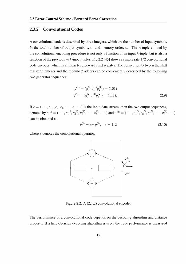
2.3.2 Convolutional Codes
A convolutional code is described by three integers, which are the number of input symbols,
k, the total number of output symbols, n, and memory order, m. The n-tuple emitted by
the convolutional encoding procedure is not only a function of an input k-tuple, but is also a
function of the previous m k-input tuples. Fig.2.2 [45] shows a simple rate 1/2 convolutional
code encoder, which is a linear feedforward shift register. The connection between the shift
register elements and the modulo 2 adders can be conveniently described by the following
two generator sequences:
g(1) = (g(1)0 g
(1)1 g
(1)2 ) = (101)
g(2) = (g(2)0 g
(2)1 g
(2)2 ) = (111). (2.9)
If c = (· · · , c−1, c0, c1, · · · , cl, · · · ) is the input data stream, then the two output sequences,
denoted by v(1) = (· · · , v(1)−1, v
(1)0 , v
(1)1 , · · · , v
(1)l , · · · ) and v(2) = (· · · , v
(2)−1, v
(2)0 , v
(2)1 , · · · , v
(2)l , · · · )
can be obtained as
v(i) = c ∗ g(i), i = 1, 2 (2.10)
where ∗ denotes the convolutional operator.
Figure 2.2: A (2,1,2) convolutional encoder
The performance of a convolutional code depends on the decoding algorithm and distance
property. If a hard-decision decoding algorithm is used, the code performance is measured
15

2.3 Error Control Scheme - Forward Error Correction
by Hamming distance. The minimum free distance of a convolutional code is defined as
the minimum Hamming distance between any two code sequences, which is the minimum
weight of all non-zero code sequences of any length. If a soft-decision decoding algorithm is
used, the code performance is measured by Euclidean distance. The minimum free Euclidean
distance is defined as the minimum Euclidean distance between any two code sequences. It
depends on both the convolutional code trellis and modulation type.
2.3.3 Maximum Likelihood Decoding
The above section explains the operation of a convolutional encoder. To consider the decod-
ing of a convolutional code, first, we describe the underlying theory of maximum likelihood
decoding, and then present a practical implementation of the decoding algorithm, the Viterbi
algorithm [7, 46].
In Fig.2.1, the task of the decoder is to produce an estimate c of the information sequence c
based on the received sequence r. Since there is a one-to-one correspondence between the
information sequence c and the codeword v, the decoder can produce an estimate v of the
codeword v. A decoding rule is a strategy for choosing an estimated codeword v for each
possible received sequence r. If the codeword v is transmitted, a decoding error occurs if
and only if v 6= v. Given that r is received, the conditional error probability of the decoder
is defined as [7]
P (E|r) , P (v 6= v|r). (2.11)
Then the error probability of the decoder can be calculated as
P (E) =∑
r
P (E|r)P (r), (2.12)
in which P (r) is the probability of the received sequence r and is independent of the de-
coding rule employed. Hence, an optimum decoding rule, which minimizes P (E), must
minimize P (E|r) in Eq.(2.11). Since minimizing P (v 6= v|r) is equivalent to maximizing
P (v = v|r), therefore, by using Bayes’ rule we get
P (v|r) =P (r|v)P (v)
P (r). (2.13)
16

2.3 Error Control Scheme - Forward Error Correction
So, v is chosen as the most likely codeword, given that r is received. In most cases, all
information sequences, and hence all codewords, are equally likely in practice. Therefore,
maximizing Eq.(2.13) is equivalent to maximizing the P (r|v). A decoder that selects its
estimate by maximizing P (r|v) is called a maximum likelihood decoder.
2.3.4 Viterbi Algorithm
The Viterbi algorithm was proposed for the decoding of convolutional codes. It is applicable
as a solution to various communication estimation problems, as long as the system can be
modeled as a finite state machine (FSM) and represented by a time-invariant or time-varying
trellis diagram [47]. We consider the system model using convolutional codes. The VA
performs MLD by tracing through the trellis of the code. The trellis diagram of a (n,k,m)
convolutional code has 2km states and 2k branches leaving and entering each state.
Assume an information sequence c = (c0, c1, · · · , ch−1) of length kh, is encoded into a
codeword v = (v0, v1, · · · , vh+m−1) of length N = n(h + m). The received sequence is
denoted by r = (r0, r1, · · · , rh+m−1). As a result, the decoder needs to produce an estimate
v of the codeword v based on the received sequence r. The criterion is to let the decoder
choose v as the codeword v that maximizes the log-likelihood function logP (r|v) [7]
P (r|v) =h+m−1∏
i=0
P (ri|vi), (2.14)
The equation is equivalent to
logP (r|v) =h+m−1∏
i=0
logP (ri|vi), (2.15)
where logP (r|v) is called the path metric and logP (ri|vi) is the branch metrics for branch
i [45].
The VA traces through all possible paths in the trellis and at each step compares the metrics
of all paths entering each state and stores the path with the largest metric, called the survivor.
The survivor at each state is then stored along with its metric. The VA can be summarized as
follows:
17

2.3 Error Control Scheme - Forward Error Correction
• Step 1. At time t = 1, compute the branch metric for the single branch entering each
state. Store the branch (the survivor) and its metric for each state.
• Step 2. Increase t by 1, compute the partial metric for each path entering a state by
adding the branch metric entering that state to the metric of the connecting survivor at
the preceding trellis depth. For each state, store the path with the largest metric (the
survivor) along with its metric, and eliminate all other paths.
• Step 3. Repeat Step 2 until the code sequence is decoded.
2.3.5 Turbo Codes
It is well known that using a serial concatenated two levels of coding, an inner and outer
code linked by an interleaver, can achieve a low error rate and dramatically decrease the
overall decoding complexity compared with that of a single code of the corresponding per-
formance [48]. The low complexity is attained by decoding each component code separately.
In decoding these concatenated codes, the inner decoder may use a soft-input soft-output
(SISO) decoding algorithm to produce soft decisions for the outer decoder.
Turbo codes employ a similar idea of concatenating two codes and separating them by a
random interleaver [6]. Rather than using a serial concatenation, two identical recursive
systematic convolutional (RSC) codes in turbo codes are connected in parallel. A block
diagram of a rate 1/3 turbo encoder is shown in Fig.2.3 [45]. In the encoder, the same
information sequence is encoded twice but in a different order. The first output sequence v0
is equal to the input sequence c since the encoder is systematic; the first RSC encoder also
produces the second parity sequence output, denoted by v1. The third output sequence v2 is
produced by the second RSC encoder with an interleaved version of the input sequence, c,
as the input.
Turbo and serial concatenated codes can be decoded by using a maximum a posteriori prob-
ability (MAP) algorithm and a soft output Viterbi algorithm. The MAP uses a decoding
criterion that minimizes the symbol or bit error probability, whereas the SOVA minimizes
the sequence error probability to generate soft output information [45].
18

2.3 Error Control Scheme - Forward Error Correction
Figure 2.3: A rate 1/3 turbo encoder
2.3.6 Soft Output Viterbi Algorithm
The soft output Viterbi algorithm produces soft output to overcome the drawback of the VA,
which generates hard symbol estimates [49].
The SOVA estimates the soft output information for each transmitted binary symbol in the
form of the log-likelihood function Λ(ct), as follows:
Λ(ct) = logPr{ct = 1|rτ
1}Pr{ct = 0|rτ
1}, (2.16)
where rτ1 is the received sequence and Pr{ct = i|rτ
1}, i = 0, 1, is the a posteriori probability
(APP) of the transmitted symbol, which is given by [45]
Pr{ct = 1|rτ1} =
eΛt
1 + eΛt
Pr{ct = 0|rτ1} =
1
1 + eΛt. (2.17)
The SOVA decoder makes a hard decision by comparing Λ(ct) to a threshold value which is
equal to zero
ct =
1 ifΛ(ct) ≥ 0
0 otherwise.(2.18)
The decoder selects the path x with the minimum path metric µτ,min as the ML path in the
19

2.3 Error Control Scheme - Forward Error Correction
same way as the VA. The probability of selecting this path is proportional to
Pr(c|rτ1) = Pr(x|rτ
1) ∼ e−µτ ,min. (2.19)
Let us denote by µt,c the minimum path metric of the paths with the complementary symbol
to the ML symbol at time t. If the ML symbol at time t is 1, then its complementary symbol
is 0. Therefore, we can write
Pr(ct = 1|rτ1) ∼ e−µτ ,min
Pr(ct = 0|rτ1) ∼ e−µt,c . (2.20)
Let µ1t represent the minimum path metric for all paths for which ct is 1 and µ0
t the minimum
path metric for all paths for which ct is 0. There are two cases to be considered to calculate
the logarithm ratio of each transmitted binary symbol.
1. If the ML estimate at time t is 1, its complementary symbol at time t is 0. Therefore,
µ1t = µτ,min and µ0
t = µt,c.
2. If the ML estimate at time t is 0, its complementary symbol at time t is 1, giving
µ1t = µt,c and µ0
t = µτ,min.
For both cases, the log-likelihood ratio (LLR) can be expressed as
logPr{ct = 1|rτ
1}Pr{ct = 0|rτ
1}∼ log
e−µt,c
e−µτ,min= µτ,min − µt,c = µ0
t − µ1t , (2.21)
Λ(ct) ∼ µ0t − µ1
t . (2.22)
Then, the difference between the minimum path metric among all the paths with symbol 0
at time t and the minimum path metric among all the paths with symbol 1 at time t is the
soft output of the decoder. The sign of Λ(ct) determines the hard estimate at time t and its
absolute value represents the soft output information that can be used for decoding in the
next stage.
20

2.3 Error Control Scheme - Forward Error Correction
2.3.7 Iterative SOVA Decoding of Turbo Codes
It is possible to use the SOVA algorithm to proceed with iterative decoding of turbo codes
[50]. The iterative turbo decoding consists of two component decoders serially concatenated
via an interleaver, identical to the one in the encoder. The block diagram of the iterative
SOVA decoder is shown in Fig.2.4.
The first SOVA decoder takes as input the received information sequence r0 and the received
parity sequence generated by the first encoder r1. The decoder then produces a soft output,
which is interleaved and used to produce an improved estimate of the APPs of the informa-
tion sequence, referred to as the extrinsic information (EI) for the second decoder.
The other two inputs to the second SOVA decoder are the interleaved received information
sequence r0 and the received parity sequence produced by the second encoder r2. The second
SOVA decoder also produces a soft output which is used to improve the estimate of the APPs
for the information sequence at the input of the first SOVA decoder in the next decoding
operation.
The EIs for the first and second decoders can be respectively given by [45],
Λ(r)2e (ct) = Λ
(r)2 (ct)− 4rt,0 − Λ
(r)1e (ct)
Λ(r)1e (ct) = Λ
(r)1 (ct)− 4rt,0 − Λ
(r−1)2e (ct), (2.23)
where Λ(r)1 (ct) and Λ
(r)2 (ct) are the LLRs of the first and second SOVA decoders; they can be
calculated from Eqs.(2.21) and (2.22), respectively; rt,0 and rt,0 are the received information
signal and interleaved version of that respectively; Λ(r−1)2e (ct) and Λ
(r)1e (ct) are the interleaved
version of the EIs for the first and second SOVA decoders respectively.
After a certain number of iterations, the decoders stop producing further performance im-
provements. At the last stage of decoding, the second decoder makes hard decisions based
on Eq.(2.18).
21

2.3 Error Control Scheme - Forward Error Correction
Figure 2.4: An iterative turbo code decoder based on the SOVA algorithm
22

2.4 Error Control Scheme - Automatic Repeat Request
2.4 Error Control Scheme - Automatic Repeat Request
In the previous section, we discussed some forms of FEC. This section is devoted to three
standard versions of the ARQ scheme, which is referred to as an error detection strategy:
• Stop-and-wait (SW) ARQ
• Go-back-N (GBN) ARQ
• Selective-repeat (SR) ARQ
2.4.1 Stop-and-wait ARQ
The SW scheme represents the simplest ARQ procedure. In an SW ARQ error-control sys-
tem, the transmitter sends a codeword to the receiver and waits for an acknowledgement, as
shown in Fig.2.5 [8]. An ACK from the receiver indicates that the transmitted codeword has
been successfully received, and the transmitter can send the next codeword. A NAK from the
receiver indicates that the transmitted codeword has been detected in error, the transmitter
needs to resend the previous codeword and waits for an acknowledgement. Retransmission
continues until the transmitter receives an ACK or the maximum retransmission number is
reached.
Figure 2.5: Stop-and-wait ARQ
The principal advantage of SW ARQ is its simplicity. But the inefficiency is its inevitable
disadvantage because of the idle time spent waiting for an acknowledgement of each trans-
mitted codeword. With the high data rates and utilization of satellite channels of long round-
trip delays, the continuous ARQ is established to replace the SW procedure.
23

2.4 Error Control Scheme - Automatic Repeat Request
2.4.2 Go-back-N ARQ
In a go-back-N ARQ system [8], codewords are transmitted continuously. The transmitter
keeps sending a new codeword, as soon as it has completed sending one, without waiting for
an acknowledgment, as illustrated in Fig.2.6. The acknowledgment for a codeword arrives
after a round-trip delay, which is defined as the time interval between the transmission of a
codeword and the receipt of an acknowledgment for that codeword. The other N − 1 code-
words can be transmitted during this interval. The transmitter goes back to the codeword,
which is negatively acknowledged, and resends that specified codeword, say codeword i,
and subsequent N − 1 codewords that were transmitted during the round-trip delay. At the
receiver, the receiver discards the erroneously received codeword and the succeeding N − 1
codewords, regardless of whether they are error-free or not. Retransmission continues until
the codeword i is positively acknowledged, and then the transmitter proceeds to transmit new
codewords.
Figure 2.6: Go-back-N ARQ with N = 7
Because of the continuous transmission and retransmission of codewords, the go-back-N
ARQ scheme is more effective than the SW ARQ. However, it becomes ineffective when the
round-trip delay is large and the data transmission rate is high. This inefficiency is caused
by the retransmission of next N − 1 received codewords, even though many of them may be
error-free. This defect can be overcome by using selective-repeat ARQ.
24

2.5 Error Control Scheme - Hybrid Automatic Repeat Request
2.4.3 Selective-repeat ARQ
In a selective repeat ARQ system, codewords are also transmitted continuously, however,
the transmitter only resends those codewords that are negatively acknowledged, as shown in
Fig.2.7 [8]. Since the user needs to receive the codewords in the right order, a buffer has to
be provided at the receiver to store the error-free received codewords. When the repeated
transmitted codeword is successively received, the receiver can then release the error-free
codewords in consecutive order.
Figure 2.7: Selective-repeat ARQ
The selective-repeat ARQ is the most efficient scheme among the three basic ARQ schemes,
but it is also the most complex one to implement.
2.5 Error Control Scheme - Hybrid Automatic Repeat Re-
quest
The two categories of techniques for controlling transmission errors in data communication
systems have disadvantages. For example, in an FEC communication system,
• The received codeword needs to be decoded even it has been detected in error, and the
decoded message has to be delivered to the user, regardless of whether it is correct or
not.
25

2.5 Error Control Scheme - Hybrid Automatic Repeat Request
• To obtain high system reliability, a long powerful code must be used and a large col-
lection of error patterns must be corrected. This makes decoding difficult to implement
and expensive [9].
In contrast, in an ARQ communication system, the throughput is not constant and it falls
rapidly with increasing channel error rate, which is the primary weakness of the ARQ
scheme.
Drawbacks of FEC and ARQ schemes can be overcome if the two basic error control schemes
are properly combined. A HARQ scheme [9, 10, 51–53] is the approach to an error control
strategy, which incorporates both FEC and ARQ. The HARQ system consists of a FEC
subsystem contained in an ARQ system. By correcting the most frequently occurring error
patterns, the FEC system can reduce the frequency of retransmission, increasing the system
performance. However, when a less-frequent error pattern occurs and is detected, the receiver
requests a retransmission rather than passing the unreliably decoded message to the user.
This increases the system reliability. As a result, an appropriate combination of FEC and
ARQ can offer better system performance.
The HARQ scheme can be classified into three categories, namely the type-I HARQ (repeti-
tion coding) scheme, which includes a pure type-I HARQ scheme and type-I HARQ scheme
with Chase combining [32], the type-II HARQ (increment redundancy) scheme and type-III
HARQ (a modified HARQII) scheme.
2.5.1 Type-I HARQ Scheme
The design of type-I HARQ scheme consists of selecting a fixed code with a certain rate and
correction capability matched to the protection requirement of all the data to be transmitted
and adapted to the average or worst channel conditions to be expected [54]. With or with-
out using the buffer to store the previously received erroneous codeword, the type-I HARQ
scheme can be divided into two subtypes, the pure type-I HARQ scheme and type-I HARQ
scheme with Chase combining.
26

2.5 Error Control Scheme - Hybrid Automatic Repeat Request
2.5.1.1 Pure Type-I HARQ Scheme
A pure type-I HARQ scheme uses a code which is designed for simultaneous error correction
and error detection [8]. When a received codeword is detected in error, the receiver first
attempts to correct the errors. As long as the number of errors are within the designed error-
correcting capability of the code, the errors will be corrected and the decoded message will
be delivered to the user. If the receiver detects an uncorrectable error pattern, it rejects the
received codeword and asks for a retransmission. When the retransmitted same codeword
is received, the receiver attempts to correct the errors (if any) again. The procedure will
continue until the codeword is either successfully received or correctly decoded.
2.5.1.2 Type-I HARQ Scheme with Chase Combining
In 1977, Sindhu [55] discussed a scheme to use all the available packets at the receiver. The
basic idea behind this technique is that a received packet which is determined to contain
errors should not be discarded, because it contains useful information about the transmit-
ted packet. If the transmission of this packet is also in error, the collective information
present in the first packet and the retransmission can be used to correct certain errors in
the two packets. Therefore, a single combined packet is more reliable than any of its con-
stituent packets. Chase [32] further developed a practical and effective combining approach,
known as Chase combining, for overcoming the problem of obtaining reliable communica-
tions when the actual channel capacity is unknown. When combining, packets should be
weighted according to their relative reliability. Such a combining strategy can operate in a
very high-error environment to achieve error-free results for all channels with finite capacity.
These features were proved to be useful for a wide range of applications, as indicated in
other literature [13, 29, 30, 56, 57].
2.5.2 Type-II HARQ Scheme
The type-I HARQ scheme is best suited for the communication systems wherein a fairly
constant level of noise and interference is anticipated on the channel [8]. In this scenario, the
error symbols of the received codewords can be corrected by the designed error-correcting
27

2.5 Error Control Scheme - Hybrid Automatic Repeat Request
code, thereby greatly reducing the number of retransmissions and enhancing the system per-
formance. However, for a non-stationary channel in which the bit error rate changes, the
type-I HARQ scheme has some shortcomings:
• When the channel condition is good, which means the channel BER is low, the trans-
mission is smooth and no error correction is needed. Therefore, the extra designed
error-correcting code is wasted during each transmission.
• When the channel is very noisy, the error-correcting capability may become inade-
quate. As a result, the frequency of retransmission increases and thus reduces the
throughput.
The type-II HARQ scheme is proposed to overcome such drawbacks of the type-I HARQ
scheme. The basic idea is to design an adaptive HARQ scheme. When the channel is quiet,
the transmitted codeword includes the information symbols, none or a few parity symbols in
each transmission, and the system behaves like the ARQ system. However, if the channel
becomes noisy, as long as the receiver detects the errors in the received codeword, it saves
the erroneously received codeword in the buffer, and at the same time requests a retrans-
mission. During the retransmission procedure, the IR codes are transmitted to the receiver
until a powerful enough codeword is formed to achieve error-free decoding. This scheme is
indicated in Fig.2.8.
Figure 2.8: Type-II HARQ scheme
28

2.5 Error Control Scheme - Hybrid Automatic Repeat Request
The type-II HARQ scheme can be incorporated with a rate 1/2 convolutional code using
Viterbi decoding [58–60]. Rate 1/N convolutional codes are punctured periodically with
period P to obtain a family of codes with rate P/(P + l), where l can be varied between
1 and (N − 1)P [61, 62]. In [11], a concept of RCPC codes was proposed, where a rate
compatibility restriction implies that all the code symbols of a high rate punctured code are
used by lower rate codes. Since codes are compatible, rate variation within a data frame is
possible to achieve unequal error protection (UEP). Fig.2.9 depicts an example of an RCPC-
ARQ system.
Figure 2.9: An example of an RCPC-ARQ system
An extension of the RCPC concept is applied to the HARQ system employing rate-compatible
punctured turbo (RCPT) codes. The resulting system provides a powerful low-rate error cor-
rection capability at low SNR and outperforms the RCPC codes for sufficiently large block
size [13].
2.5.3 Type-III HARQ Scheme
The main drawback of the type-II HARQ scheme is that additional incremental code symbols
sent for a packet received with errors are not in general self-decodable [63]. The decoder has
to rely on both the previous received packets as well as the current additional incremental
code symbols for decoding, in situations wherein a current transmitted IR packet can be
lost or severely damaged as a result of interference. Kallel [63] modified the type-II HARQ
scheme by exploiting the complementary punctured convolutional (CPC) codes. Briefly,
29

2.5 Error Control Scheme - Hybrid Automatic Repeat Request
the CPC codes are composed of a set of equivalent codes with the same rate and distance
spectrum from the same original mother code. Due to its self-decodable property, the type-
III HARQ procedure has the choice of extracting the source information either from the last
received packet or by combining all previous packets, as is generally the case with the type-II
HARQ scheme.
30

Chapter 3
Introduction to Cooperative Diversity
In wireless communication systems, significant attenuation and fading limit the channel ca-
pacity of a specific communication link or an entire network, which could hamper the ability
of a wireless network to deliver services with the same level of quality as that guaranteed
by a wired system. This challenge is compounded by growing demands from services that
require high data-rate transmission. One of the primary solutions is to create some form
of diversity by transmitting and processing redundant signals over essentially independent
channels. The multiple-input multiple-output and cooperative diversity techniques are two
well-known techniques to achieve transmission diversity.
Section 3.1 gives a brief review of the MIMO and CD techniques. A variety of CD pro-
tocols, including fixed, selection, and incremental relaying, are described in section 3.2.
Section 3.3 introduces two main coded cooperation schemes, the distributed rate compatible
convolutional codes, and distributed turbo coding schemes, which are widely used in the CD
communication systems.

3.1 Introduction
3.1 Introduction
3.1.1 Multiple-input Multiple-output Technique
Multiple-input multiple-output communication techniques have been an important area of
focus for the next-generation wireless systems because of their potential for high capacity,
increased diversity, and interference suppression [18].
A MIMO channel with nT transmitters and nR receivers is typically represented as a matrix
H of dimension nR×nT , where each of the coefficients [H]i,j represents the transfer function
from the jth transmitter to the ith receiver, as shown below:
H =
h1,1 h1,2 · · · h1,nT
h2,1 h2,2 · · · h2,nT
· · ·hnR,1 hnR,2 · · · hnR,nT
. (3.1)
We denote the signal or symbol transmitted from the jth transmitter as xj , and collect all
such symbols into an nT -dimensional vector x. With this notation, the matrix model of the
channel is
y = Hx + n, (3.2)
where n is a vector of additive noise, and y is the vector of received data, with an element in
n and y for each receive antenna.
This system, as shown in Fig.3.1, is implemented with an antenna array at both the transmit-
ter and receiver in conjunction with using sophisticated coding, aiming to create separated
transmission paths that experience independent fades. The MIMO channel can be provi-
sioned for higher data rates, resistance to multipath fading, lower delays, and support for
multiple users.
32

3.1 Introduction
Figure 3.1: MIMO wireless link
3.1.2 Cooperative Diversity Technique
The MIMO technique is a successful method that can provide both spatial and temporal
diversities to effectively mitigate the detrimental effects of fading for point-to-point channels
[16, 17, 64, 65].
However, in reality, due to size, cost, or hardware limitations, the antenna array can hardly
be implemented on a small platform such as a mobile handset (size) or wireless sensor nodes
(size, power). Recently, a new form of spatial-temporal diversity has been created, namely
cooperative diversity, which allows single-antenna mobiles to reap some of the benefits of
MIMO systems [19–21]. The essence of the CD technique is that single-antenna mobiles
in a multi-user scenario can “share” their antennas in a manner that creates a virtual MIMO
system. Based on this virtual array, the devices are able to share their distributed resources
such as bandwidth and power by relaying each other’s data in a cooperative way. Fig.3.2
shows the basic idea behind this concept, where by two users cooperate with each other to
communicate with a remote base station. Since each user has an independent fading path to
the destination, spatial diversity is generated by transmitting signals from different locations.
When the direct path between the source and destination is in deep fade or blocked by an
obstacle, due to the broadcast nature of the wireless medium, the relay likewise experiences
33

3.2 Cooperative Diversity Protocols
better receive conditions than the destination and thus can offer the “overheard” information
to the destination. Therefore, the combined signals at the destination can increase the overall
received SNR.
Figure 3.2: A model of a cooperative communication technique
Since the cooperating partners in the CD communication systems are geographically sepa-
rated, the spacing between any pair of users, and hence their antennas, is wider than that of
a conventional MIMO system. Therefore, the CD technique is immunized not only against
small-scale channel fading but against large-scale channel fading.
3.2 Cooperative Diversity Protocols
In this section, we describe a variety of cooperative diversity protocols that can be utilized in
the network of Fig.3.2, including fixed, selection, and incremental relaying protocols.
3.2.1 Fixed Relaying Protocols
For the fixed relaying, the relay either amplifies its received signals subject to its power
constraint, or decodes, re-encodes and retransmits the message to the destination. The de-
scription for each of them is summarized as follows.
In a CD communication system, the source and relay transmit data through orthogonal chan-
nels [19, 20, 25, 39, 66, 67], which could be implemented through time, frequency or code-
division multiple access. In a time division duplexing (TDD) scheme, time is slotted and
34

3.2 Cooperative Diversity Protocols
the CD communication process needs two time slots. In the first time slot, the source first
broadcasts its message to both the relay and destination. The received signals at the relay
and destination, at time t, denoted by ysr(t) and ysd(t) can be expressed as
ysr(t) =√
Psrhsrx(t) + nsr(t), (3.3)
ysd(t) =√
Psdhsdx(t) + nsd(t), (3.4)
where Psr, Psd are the received signal power at the relay and destination respectively.
Upon receiving ysr(t), during the next time slot, the relay processes the received signal and
sends it to the destination. Let xr(t) represent the signal transmitted from the relay at time t.
It satisfies the following transmit power constraint,
E(|xr(t)|2) ≤ Pr, (3.5)
where Pr is the transmitted power limit at the relay.
For the second time slot, the destination receives the signal as
yrd(t) = Grdhrdxr(t) + nrd(t). (3.6)
3.2.1.1 Amplify and Forward
For amplify and forward transmission, the appropriate channel model is Eq.(3.3)-Eq.(3.6).
Each user in this method receives a noisy version of the signal transmitted by its partner. The
user then amplifies the received signal and then forwards it to the destination. The signal
transmitted from the relay can be written as
xr(t) = µysr(t), (3.7)
35

3.2 Cooperative Diversity Protocols
where µ is an amplification factor that depends on the transmit signal power, noise spectral
power density and fading attenuation. It can be calculated from Eqs.(3.3) and (3.5) as
µ ≤√
Pr
|hsr|2Psr + N0
. (3.8)
The destination combines the signals sent by the source and relay as
wsdysd(t) + wrdyrd(t)
= wsd [hsds(t) + nsd(t)] + wrd {hrdµ [hsrs(t) + nsr(t)] + nrd(t)} , (3.9)
where the combining coefficients can be calculated as [68]
wsd =
√Psdh
∗sd
N0
, wrd =µ√
Psrh∗rdh
∗sr
(µ2|hrd|2 + 1)N0
. (3.10)
Although noise is amplified by cooperation, the base station receives two independently
faded versions of the signal and can make a better decision on the detection of information.
3.2.1.2 Decode and Forward
For decode and forward transmission, the appropriate channel is again Eq.(3.3)-Eq.(3.6).
The relay decodes the received signal, then re-encodes and forwards it with power Pr to the
destination.
xr(t) =√
Prx(t), (3.11)
The corresponding received signal at the destination can be expressed as
yrd(t) = Grdhrd
√Prx(t) + nrd(t). (3.12)
3.2.2 Selection Relaying Protocol
In the fixed DAF protocol, the relay always forwards the decoded information to the desti-
nation. This protocol suffers performance loss if the relay cannot decode the transmitter’s
36

3.2 Cooperative Diversity Protocols
signal correctly. To overcome the drawbacks of the fixed relaying transmission, the author
in [21] also proposed adaptive relaying protocols, including selection relaying and incremen-
tal relaying protocols.
The signal transmission in the selection relaying protocol still involves two time slots. In
the first time slot, each source sends information to its destination, and the information is
also received by other users in the network. In the second time slot, the relay decodes the
received information and forwards the decoded information symbols only if the amplitude
of the measured channel coefficient of source to the relay channel is larger than a certain
threshold, otherwise, the relay does not send and remains idle [21].
The wireless link in the network is subject to fading and additive noise. Although the fading
coefficients can be well estimated by the cooperation terminal, the additive noise is unknown
to the receiver. To take into account both the effect of channel fading and the effect of additive
noise, the author in [69] proposed an optimum threshold selection relaying scheme, which
adapts based on the received signal power at the relay terminal. The relay decides whether,
or not to forward the signal it receives from the source, by comparing the squared amplitude
of the received signal, normalized by the average noise power, with a certain threshold.
3.2.3 Incremental Relaying Protocol
Since the relay repeats all the time, the fixed and selection relaying make inefficient use of
the degrees of freedom of the channel. Using a single bit indicating the success or failure of
the direct transmission, from the source to the destination, the relay retransmits in an attempt
to exploit spatial diversity.
As an example, the source broadcasts its information to the relay and destination. After de-
coding the received signal, the destination indicates the received signal status (either correct
or erroneous) by broadcasting a single bit of feedback to the source and relay. If the SNR
between the source and destination channel is sufficiently high, the feedback indicates the
correctly received signal from the source, and the relay remains idle. Otherwise, based on
the received feedback from the destination, the relay needs to forward its received signal to
the destination using either the AAF or DAF transmission protocols.
This incremental relaying protocol can be treated as extensions of incremental redundancy,
37

3.3 Coded Cooperation Schemes
or HARQ, to the relay context. Since the relay rarely repeats, the protocol of this form makes
more efficient use of the degrees of freedom of the channel.
3.3 Coded Cooperation Schemes
Coded cooperation [23] is a method that integrates cooperation into channel-coding. Coded
cooperation works by transmitting different portions of each user’s codeword via two inde-
pendent fading paths. The idea is that each user tries to send incremental redundancy to
its partner. Whenever the case is impossible, the users automatically revert to a noncoop-
erative mode. Since the coded cooperation is managed automatically through code design,
there is no feedback involved between the users, thus allowing coded cooperation to achieve
efficiency.
3.3.1 Distributed Rate Compatible Convolutional Codes
In the distributed rate compatible convolutional codes scheme (also termed as user cooper-
ative coding [25]), each user encodes blocks of K source bits using a concatenation of a
CRC code followed by a prescribed code from a family of RCPC codes [23]. The length
of coded bits per block is N , so the overall code rate is R = K/N . The N coded bits are
divided into two segments, with the first segment being a punctured rate R1 codeword with
N1 = K/R1, and the second being the N2, which represents the remaining parity bits for the
rate R codeword, where N1 + N2 = N .
The users cooperate by dividing the transmission of their N -bit code words into two frames.
In the first frame, N1 is broadcasted by each user, and is received by the base station as well
as the partner. Each user thus receives a noisy version of the coded packet from its partner. If
the partner’s packet is successfully decoded based on the CRC check, the user calculates and
transmits the partner’s N2 remaining parity bits in the second frame. Otherwise, the user’s
own parity bits are transmitted. The framework of this scheme is illustrated as in Fig.3.3 [70].
The users act independently in the second frame, with no knowledge of whether their own
first frame was correctly decoded. As a result, there are four possible cooperative scenarios
38

3.3 Coded Cooperation Schemes
Figure 3.3: Block diagram of the distributed rate compatible puncture convolutional codes
for the second frame transmission: both users cooperate, neither user is cooperative, user 1
is cooperative but user 2 is not, and vice versa. A further comprehensive description and
analysis can be referred to in the literature [71, 72].
3.3.2 Distributed Turbo Codes
Since cooperative coding contains two code components, it is natural to apply turbo codes
[24]. For the sake of brevity, we omit the duplex transmission between the users, and only
consider a half-duplex transmission channel (from user 1 to user 2 ) for this scheme’s descrip-
tion. Recall that with turbo codes, the data is recursively encoded twice, first in its natural
order and again after being interleaved [73]. In a DTC scheme, each user employs a very
simple code, for example, a two-state rate 1/2 RSC code, and an interleaver is added to user
2. Upon successful decoding of the partner (user 1), the user 2 interleaves user 1’s source
symbols and re-encodes them. Thus, the uninterleaved encoding is present in the user 1 to
base station channel, while the interleaved encoding is present in the user 2 to base station
39

3.3 Coded Cooperation Schemes
channel. Then the users have cooperatively constructed a distributed turbo code [25, 39], the
base station can detect the code iteratively by using a standard turbo decoder. The imple-
mentation of coded cooperation using distributed turbo codes is shown in Fig.3.4.
Figure 3.4: Block diagram of the distributed turbo coding technique
40

Chapter 4
Collaborative HARQ Schemes in
Wireless Networks
4.1 Introduction
In conventional wireless networks, traditional multihop protocols were treated as a cascade of
point-to-point links, with each radio directing its transmission to only a single receiver [74].
The quality of the signal received by the destination depends on various factors, for example,
path loss, fading and noise. To guarantee reliable transmission over a radio channel, ARQ
or HARQ protocols are usually adopted. The retransmission protocol specifies how data
packets that are not correctly received and detected by the destination must be retransmitted
from the source until they are successfully delivered. As other neighboring nodes do not
take part in the packet retransmission process, these ARQ/HARQ protocols are referred to
as non-collaborative.
However, one peculiar characteristic of the wireless networks is the inherent broadcast-
oriented nature of radio. Beside the intended destination, a signal transmitted by a source
may be also received by other neighboring nodes that are within earshot. In contrast with
non-collaborative ARQ/HARQ, retransmitted packets do not need to come from the original
source but could instead be sent by relays that overhear the transmission [26]. Therefore,

4.1 Introduction
the spatial diversity is provided by the relays and the protocol is referred to as collaborative
HARQ.
As a consequence, when the relay retransmits, various relaying protocols can be utilized in
cooperative wireless networks, including fixed, selection, incremental [21], compress and
forward [75] protocols etc. Compared with other relaying protocols, AAF and DAF are two
popular protocols and are frequently used in the cooperative systems [15, 76–78].
In an AAF scheme, each user receives a noise version of the signal transmitted by its partner.
Then the parter amplifies and retransmits this noise version. The destination combines the
packets sent by the user and partner, and makes a final decision on the transmitted packet.
In a DAF scheme, there are two possible policies to achieve transmission at the relay:
• Selection Transmission: The relay only retransmits if it decodes the received packet
from the source correctly.
• Persistent Transmission: The relay always retransmits, even if the decoded packet is
in error, which leads to severe error propagation.
Preliminary works on the HARQ schemes have focused on the AAF and DAF relaying pro-
tocols. In the HARQ I-DAF scheme, upon the reception of a negative acknowledgement
(NAK), the relay retransmits a copy of the original packet, received from the source to the
destination [27]. In the HARQ II-DAF scheme, the source broadcasts odd-numbered sym-
bols of the codeword, the relay re-encodes the source message to obtain and transmit even-
numbered symbols of the codeword to the destination when it decodes correctly [28]. In [29],
HARQ I, HARQ II schemes with different cooperative strategies, including DAF and AAF
protocols, have been further investigated.
Obviously, in wireless networks, an AAF protocol suffers from noise amplification and a
DAF protocol leads to error propagation if the decoding packet is in error at the relay.
In this chapter, a HARQ scheme based on an adaptive relaying protocol (ARP) is proposed.
It combines retransmission mechanisms, distributed turbo coding and an adaptive relaying
protocol. When the relay is required for retransmission, it transmits either a repeated packet
or a punctured packet to the destination, depending on the types of HARQ strategies used
42

4.2 System Model
in the system. The relay switches the relaying protocol between AAF and DAF, depending
on the decoding result. If the decoding result at the relay is correct, the relay decodes the
received signal, and then interleaves, re-encodes and forwards it to the destination. The
signals received at the destination consist of a coded signal transmitted from the source
and a coded interleaved information transmitted from the relay. These two signals form a
distributed turbo code [25, 39]. Otherwise the relay amplifies and forwards the originally
received signal to the destination.
Moreover, we propose an efficient feedback strategy. Rather than using two feedback chan-
nels as in other HARQ relaying schemes, the proposed HARQ-ARP scheme has only one
broadcast feedback channel, from the destination to both the relay and source. According to
the number of received NAKs for each packet, the source and relay determine which one of
them will be used in the next time slot for retransmission. This can reduce the feedback load
and increase the transmission efficiency.
In this chapter, we mainly focus on the description of the proposed HARQ-ARP protocol.
The performance analysis for the proposed HARQ-ARP scheme is carried out in the next
chapter.
4.2 System Model
In this thesis, we study a typical two-hop relay network consisting of a source, a relay and a
destination, as shown in Fig. 3.2.
We consider a quasi-static fading channel, in which the fading coefficients are constant
within one transmission block, but change independently from one frame to another. Be-
cause of slow fading, accurate channel estimation is possible at the receiver [21, 79]. There-
fore, we assume perfect CSI at the relay and destination. The source, on the other hand, only
knows the statistics of fading, but not the current realization. Let “direct channel”, “inter-
user channel” and “relay channel” denote the channels between the source and destination,
the source and relay and the relay and destination, respectively. The fading coefficients of
the above three channels are independent. Similar to [21, 80], we assume that the source and
relay transmit orthogonal signals in a TDD scheme. Furthermore, we assume an errorless,
43

4.2 System Model
low-capacity feedback channel over which the receiving destination can transmit an ACK or
a NAK signal to the source and relay.
The transmitted information binary stream with an appended CRC coded sequence, denoted
by U, is represented by
U = (u(1), · · · , u(t), · · · , u(l)), (4.1)
where u(t) is a binary symbol transmitted at time t and l is the frame length.
The binary information sequence U is first encoded by a channel encoder. For simplicity,
we consider a recursive systematic convolutional code with a code rate of 1/2 [6]. Let Vrepresent the corresponding codeword, given by
V = (V(1), · · · , V(t), · · · , V(l)), (4.2)
where V(t) = (u(t), v(t)) is the transmitted codeword, u(t) is the information symbol and
v(t) is the corresponding parity symbol, u(t), v(t) ∈ {0, 1}.
The binary symbol stream V is then mapped into a modulated signal stream. For binary
phase shift keying (BPSK) modulation, the modulated codeword, denoted by X, is given by
X = (X(1), · · · , X(l)), (4.3)
where X = (x(t, 1), x(t, 2)), x(t, j) ∈ {−1, +1}, t = 1, · · · , l, j = 1, 2 is the modulated
signal transmitted by the source at time 2(t− 1) + j.
We impose a half-duplex constraint, so the cooperative communication process needs two
time slots. In the first time slot, the source first broadcasts its message to both relay and
destination.
The received signal at the relay, denoted by ysr(t), can be described as
ysr(t) =√
Psrhsrx(t) + nsr(t), (4.4)
where Psr = Ps · (Gsr)2 is the received signal power at the relay; Ps is the source transmit
power, Gsr =(
λc
4πd0
)(dsr
d0
)−κ/2
[81] is the gain of the inter-user channel, dsr is the distance
between the source and relay, d0 is a reference distance; λc is the carrier wavelength and κ is
44

4.2 System Model
a path-loss factor with values typically in the range 1 ≤ κ ≤ 4. hsr is the fading coefficient
of the inter-user channel. It is modeled as a zero-mean, independent circular symmetric
complex Gaussian random variable. Furthermore, nsr(t) is a zero mean complex Gaussian
random variable with the two-sided spectral density of N0/2.
Upon receiving ysr(t), in the next time slot, the relay processes the received signal and sends
it to the destination. Let xr(t) represent the signal transmitted from the relay at time t. It
satisfies the following transmit power constraint,
E(|xr(t)|2) ≤ Pr, (4.5)
where Pr is the transmitted power limit at the relay.
In the proposed scheme, the relay decodes the received signal from the source, interleaves
the decoded information symbols, re-encodes and then forwards it with power Pr to the
destination. Let U = (u(1), · · · , u(t), · · · , u(l)) represent the interleaved version of U.
Let V = (V (1), · · · , V (l)) denote the codeword of U, where V(t) = (u(t), v(t)) is the
codeword of u(t). V is then mapped into a modulated signal stream X = X(1), · · · , X(l),
where X(t) = (x(t, 1), x(t, 2)) , xt(j) is the modulated signal transmitted by the relay using
DTC, at time 2(t− 1) + j.
xr(t) =√
Prx(t). (4.6)
The corresponding received signals at the destination at time 2t− 1 and 2t, transmitted from
the source and relay, can be expressed as
ysd(t) =√
Psdhsdx(t) + nsd(t), (4.7)
yrd(t) = Grdhrdxr(t) + nrd(t), (4.8)
where Psd = Ps · (Gsd)2 is the received signal power at the destination, Ps is the source
transmit power; Gsd =(
λc
4πd0
)(dsd
d0
)−κ/2
[81] is the gain of the direct channel, dsd is the
distance between the source and destination, d0 is a reference distance; λc is the carrier
wavelength and κ is a path-loss factor with values typically in the range 1 ≤ κ ≤ 4. Grd is
the channel gain of the relay channel. hsd and hrd are the fading coefficients of the direct and
relay channel, respectively. They are modeled as zero-mean, independent circular symmetric
45

4.3 Collaborative HARQ with the ARP Scheme
complex Gaussian random variables. Furthermore, nsd(t) and nrd(t) are zero mean complex
Gaussian random variables with the two-sided spectral density of N0/2.
The overall received signals at the destination are obtained as the sum of the coded source
signal, and the coded interleaved source signal transmitted from the relay. These two sig-
nals form a standard distributed turbo code, as shown in Fig. 3.4. The received signals’
expressions are given in Eqs.(4.7) and (4.8).
4.3 Collaborative HARQ with the ARP Scheme
In this section, we present the proposed three types of HARQ schemes with ARP, denoted
by HARQ I-ARP, HARQ II-ARP and HARQ III-ARP, where ARP represents a combination
of DAF and AAF. Since the HARQ II-ARP and HARQ III-ARP protocols follow the same
retransmission rules of HARQ I-ARP, we present the HARQ I-ARP scheme in detail, and
only the differences between the type I HARQ-ARP and type II/III HARQ-ARP schemes
are described in sections 4.3.2 and 4.3.3.
For the proposed HARQ-ARP scheme, when the relay needs to retransmit, it checks the CRC
of the broadcasted signals from the source. If the decoding result is correct, the relay adopts
DAF, otherwise, it employs AAF.
In the conventional HARQ relaying schemes, two acknowledgement feedback channels are
used, one from the destination to the source and the other from the relay to the source [28]. In
contrast, the proposed scheme only needs one feedback channel. The destination examines
the CRC check to determine the decoding result and then generates an ACK or a NAK signal,
broadcasting to both the relay and source.
The proposed ARP scheme has two attractive features in a practical application, for example,
• The relay can automatically adapt to the channel quality by simply switching between
the AAF and DAF without any need for the CSI to be fed back from the destination
to the relay or source. This feature is especially desirable in practical relay networks,
particularly in a large multi-hop network, where the feedback of CSI for adaptation is
impractical.
46

4.3 Collaborative HARQ with the ARP Scheme
• Compared with the non-adaptive relaying protocols: AAF and DAF, the ARP process-
ing at the relay and destination is the same as those protocols, so it does not add any
decoding complexity.
Without loss of generality, we consider a 1/2 RSC code as a mother code, Cm, in all the
HARQ-ARP schemes.
4.3.1 Type I HARQ with the ARP Scheme
In the HARQ I-ARP scheme, the transmitter retransmits the packet when the destination
receiver detects errors in the received packet. At the destination receiver, the previous er-
roneous packets are saved and combined with the current received packet, based on the
respective SNR [32]. The retransmission can either come from the source or relay.
The transmission procedure of the HARQ I-ARP protocol is shown in Fig. 4.1 and it consists
of the following steps:
1. The source broadcasts a packet to the relay and destination and also stores the trans-
mitted packet in the buffer.
2. The reception procedure at the destination:
a. If the packet is correctly decoded, an ACK will be broadcasted to the source and
relay. The transmitter goes to step 1 to send a new packet. The relay is inactive
in this case.
b. Otherwise, a NAK will be returned to both the source and relay. The source stays
in an idle state and the relay decodes the packet.
3. Actions at the relay: based on the CRC check value, the relay makes a decision to use
either the DAF or AAF relaying protocol.
a. If the CRC check is correct, the relay uses a DAF protocol. It interleaves the
estimated information symbols, re-encodes and forwards them to the destination.
b. If the relay cannot decode correctly, the relay uses an AAF protocol. It amplifies
the received signal and forwards it to the destination.
47

4.3 Collaborative HARQ with the ARP Scheme
Figure 4.1: The proposed HARQ scheme with ARP where the relay uses either AAF or DAF
48

4.3 Collaborative HARQ with the ARP Scheme
4. Actions at the destination:
a. If the relay uses a DAF protocol, the destination receives two copies of the sig-
nal, the coded signal from the source and coded interleaved signal from the relay.
Thus, a DTC codeword is formed. An iterative decoding method is used to re-
cover the source information. Following are the operations, within the iterative
decoding loop:
∗ If the decoded packet is correct, exit the iterative decoding loop.
∗ Otherwise, continue the decoding loop until the maximum number of iter-
ations is reached. If the decoded packet is still erroneous, exit the iterative
decoding loop.
b. If the relay uses an AAF protocol, the destination combines the previous error
packet from the source and current received packet from the relay.
c. Based on the decoding result, an ACK/NAK will be broadcasted to the source
and relay.
5. Actions at the source,
a. If an ACK is received, the protocol goes to step 1 to send a new packet.
b. Otherwise, if a NAK is received, a retransmission is required and the protocol
proceeds to send the stored packet until the maximum retransmission number is
reached. In that case, the source discards the packet and goes to step 1 to send
another new packet.
From the above protocol procedure, we can see that the broadcast negative acknowledgement
can determine whether the source or relay retransmits. Within the maximum number of
transmissions, N, if the number of NAKs is odd, the source stays in an idle state and relay
retransmits the received packet to the destination. If the number of NAKs is even, the source
retransmits the original packet to the destination and relay waits for the further feedback
from the destination. For example, at the first transmission, the source broadcasts a packet
to the relay and destination, if the destination can not decode properly, the destination will
send a NAK back to the source and relay. In this scenario, the received message at the
relay will be transmitted to the destination and the source will stay in the idle state. At
the destination, if the combined packets from the source and relay still can not be decoded
49

4.3 Collaborative HARQ with the ARP Scheme
Transmission time 1st 2nd 3rd
Information symbols 11111111 00000000 00000000Parity symbols 01000010 10101000 00010101Overall code rate 4/5 8/13 1/2
Table 4.1: Puncturing table for direct channel in a HARQ II-ARP scheme with a rate 4/5code
correctly, the destination will broadcast the second NAK to the source and relay, then the
source will retransmit the message to the destination and the relay will not transmit. So
the source and relay alternatively transmit until the maximum retransmission number N is
reached. The proposed broadcast feedback channel strategy can reduce the feedback load,
increase the transmission efficiency and correspondingly decrease the transmission time.
4.3.2 Type II HARQ with the ARP Scheme
Unlike HARQ I-ARP, where the same data is repeated during each retransmission, HARQ
II-ARP uses a high-rate error control code. The source transmits incremental redundancy
symbols at each transmission step. According to the puncturing table, the relay and destina-
tion assemble previously received fragments of the packet to form a lower rate error control
code to recover the information.
Two families of RCPT codes [13] with puncturing period P = 8 are used in the proposed
HARQ II-ARP scheme, in which the optimal puncturing patterns are derived by using aver-
age distance spectra. Both code families employ a 4-state turbo code with generator polyno-
mial 5/7. To maximize capacity, the source and relay should transmit uncorrelated symbols,
but related to the same message [25]. Therefore, the source and relay encode/re-encode the
signal using different puncturing tables. The related puncturing matrices for the first to the
third transmission are shown in Tables 4.1-4.4. A zero in the puncturing table means that the
corresponding symbol of the packet is not transmitted.
50

4.3 Collaborative HARQ with the ARP Scheme
Transmission time 1st 2nd 3rd
Information symbols 11111111 00000000 00000000Parity symbols 10000001 01010100 00101010Overall code rate 4/5 8/13 1/2
Table 4.2: Puncturing table for relay channel in a HARQ II-ARP scheme with a rate 4/5 code
Transmission time 1st 2nd 3rd
Systematic bits 11111111 00000000 00000000Parity bit 11001010 00100001 00010100Overall code rate 2/3 4/7 1/2
Table 4.3: Puncturing table for direct channel in a HARQ II-ARP scheme with a rate 2/3code
4.3.3 Type III HARQ with the ARP Scheme
The type III HARQ with the ARP scheme follows the same retransmission rules of the type
II HARQ with ARP scheme. The only difference is that the packet transmitted by the trans-
mitter is self-decodable, so the relay and destination can use either the latest received packet
or the combined received packets to recover the transmitted message [63]. In the proposed
scheme, the relay and destination use the current received packets to decode. If the decoding
result is not correct, the information symbols of all the received packets are combined by
using Chase combining [32], while the parity symbols are combined by using code combin-
ing [29]. Since a set of punctured convolutional codes were derived from the same original
low rate code with the same code rate and distance properties, when they are combined, the
combined codes yield at least the mother code, Cm.
The corresponding puncturing tables for various code rates with the puncturing period P = 8
are shown in Tables 4.5-4.8.
Transmission time 1st 2nd 3rd
Systematic bits 11111111 00000000 00000000Parity bit 11010001 00100100 00001010Overall code rate 2/3 4/7 1/2
Table 4.4: Puncturing table for relay channel in a HARQ II-ARP scheme with a rate 2/3 code
51

4.3 Collaborative HARQ with the ARP Scheme
Transmission time 1st 2nd 3rd
Information symbols 11111111 11111111 11111111Parity symbols 01000010 10101000 00010101Overall code rate 4/5 8/13 1/2
Table 4.5: Puncturing table for direct channel in a HARQ III-ARP scheme with a rate 4/5code
Transmission time 1st 2nd 3rd
Information symbols 11111111 11111111 11111111Parity symbols 10000001 01010100 00101010Overall code rate 4/5 8/13 1/2
Table 4.6: Puncturing table for relay channel in a HARQ III-ARP scheme with a rate 4/5code
Transmission time 1st 2nd 3rd
Systematic bits 11111111 11111111 11111111Parity bit 11001010 00100001 00010100Overall code rate 2/3 4/7 1/2
Table 4.7: Puncturing table for direct channel in a HARQ III-ARP scheme with a rate 2/3code
Transmission time 1st 2nd 3rd
Systematic bits 11111111 11111111 11111111Parity bit 11010001 00100100 00001010Overall code rate 2/3 4/7 1/2
Table 4.8: Puncturing table for relay channel in a HARQ III-ARP scheme with a rate 2/3code
52

4.4 Simulation Results
4.4 Simulation Results
In the previous section, we presented the proposed HARQ-ARP scheme for the CD com-
munication systems in wireless networks. In this section, we illustrate the performance of
the proposed scheme and compare it with another two reference schemes, HARQ with AAF
(HARQ-AAF) and HARQ with DAF (HARQ-DAF).
In order to present equitable comparisons, we apply persistent transmission principles to
all HARQ schemes, including HARQ-AAF, HARQ-ARP and HARQ-DAF schemes. The
simulation conditions are summarized in Fig. 4.2, where the direct and relay channels have
the same SNR, which varies from 0 to 14 dB, while the inter-user channel is variable from 0
to 24 dB.
Fig.4.3 shows the FER comparison of various HARQ I schemes. It is shown that HARQ
I-DAF is superior to HARQ I-AAF by around 4 dB at FER = 10−2, due to an additional
coding gain with the DTC structure. We also observe that HARQ I-ARP outperforms HARQ
I-DAF by around 1.5 dB at FER = 10−2. When HARQ I-DAF cannot decode the received
signal correctly, the relay switches to HARQ I-AAF to forward the amplified signal to the
destination, which circumvents the error propagation introduced by HARQ I-DAF scheme
in this scenario. The destination can thus successfully decode some combined signals from
the relay and source. The limited gain comes from HARQ I-AAF’s contribution.
Figs. 4.4 and 4.5 compare the FER performance of various HARQ II schemes. Unlike the
HARQ I scheme, HARQ II-AAF’s performance is significantly better than HARQ II-DAF’s
performance. In Fig. 4.4, at FER = 10−1, the SNR gain is by around 2.5 dB, and in Fig. 4.5,
at FER = 10−1, the SNR gain is by around 2 dB, while the gain increases as the FER
decreases. The reason behind this phenomenon is that when the relay receives the first trans-
mitted high code rate punctured packet from the source, the relay cannot correctly decode it
most of the time. The process of decoding, interleaving and re-encoding introduces serious
propagation errors. Even after three transmissions, the decoding error can still occur at the
relay.
On the same figures, it is also observed that HARQ II-ARP still has the best performance.
For example, in Fig. 4.4, at FER = 10−2 HARQ II-ARP can provide SNR gains of about 1
dB and 6.5 dB compared to HARQ II-AAF and HARQ II-DAF; in Fig. 4.5, at FER = 10−2
53

4.4 Simulation Results
Figure 4.2: Simulation conditions
54

4.4 Simulation Results
Figure 4.3: FER comparison of HARQ I-AAF, HARQ I-DAF and HARQ I-ARP schemes ina quasi-static fading channel with SNR 0-8 dB of the inter-user channel
HARQ II-ARP can provide SNR gains of about 0.8 dB and 5 dB compared to HARQ II-AAF
and HARQ II-DAF. In the HARQ II-ARP scheme, when the decoding result at the relay is
correct, the DTC scheme provides a high coding gain and this improves its performance
significantly.
In Figs. 4.6 and 4.7, a similar FER performance comparison is shown for the HARQ III
schemes. We observe that HARQ III-ARP is superior to HARQ III-AAF and HARQ III-
DAF by around 1.5 dB and 4 dB at FER = 10−2 in Fig. 4.6, and by around 1.5 dB and 2.8
dB at FER = 10−2 in Fig. 4.7, respectively. In addition, HARQ III-AAF’s performance is
still better than HARQ III-DAF’s performance, due to the same reason as for HARQ II.
55

4.4 Simulation Results
Figure 4.4: FER comparison of HARQ II-AAF, HARQ II-DAF and HARQ II-ARP schemesin a quasi-static fading channel with SNR 0-8 dB of the inter-user channel; the puncturingrates for the first transmission are 4/5
Figure 4.5: FER comparison of HARQ II-AAF, HARQ II-DAF and HARQ II-ARP schemesin a quasi-static fading channel with SNR 0-8 dB of the inter-user channel; the puncturingrates for the first transmission are 2/3
56

4.4 Simulation Results
Figure 4.6: FER comparison of HARQ III-AAF, HARQ III-DAF and HARQ III-ARPschemes in a quasi-static fading channel with SNR 0-8 dB of the inter-user channel; thepuncturing rates for the first transmission are 4/5
Figure 4.7: FER comparison of HARQ III-AAF, HARQ III-DAF and HARQ III-ARPschemes in a quasi-static fading channel with SNR 0-8 dB of the inter-user channel; thepuncturing rates for the first transmission are 2/3
57

4.5 Conclusion
4.5 Conclusion
In this chapter, we studied the collaborative HARQ schemes for the cooperative diversity
systems in wireless networks. According to the decoding result at the relay, we proposed
an adaptive relaying protocol over the quasi-static fading channel. The proposed HARQ-
ARP scheme combines the retransmission mechanisms (repetition coding and incremental
redundancy), the distributed turbo coding and the proposed adaptive relaying strategy. Based
on the different HARQ strategies, Chase combining and code combining were applied at the
receiver. The simulation results indicated that the proposed HARQ-ARP scheme can achieve
a superior FER compared to the reference schemes in all SNR regions.
58

Chapter 5
Performance Analysis of Collaborative
HARQ Schemes in Wireless Networks
In the previous chapter, we proposed an adaptive relaying protocol and used it in the collab-
orative HARQ protocols for the CD communication systems. In this chapter, we present a
theoretical analysis of the proposed HARQ-ARP scheme. The pairwise error probabilities
(PEP) and word error probabilities (WEP) for all the HARQ schemes are derived for BPSK
over a quasi-static fading channel. We then give a general throughput and FER expression
for each HARQ scheme. Finally, we compare the performance with the reference systems,
the HARQ-AAF scheme and HARQ-perfect DTC scheme, in which the received packet at
the relay is assumed to be correct.
5.1 WEPs of the Relaying Protocols in the HARQ I Schemes
The calculation of the traditional union bound requires knowing the code distance spectrum,
which necessitates an exhaustive search of the code trellis. Due to the high complexity of
this search, similar to [82, 83], we consider an average upper bound. In order to calculate the
WEP of HARQ-ARP, we need to know the probability of the erroneous or correctly received
packet at the relay, that is, the probability of using either the HARQ-AAF or HARQ-perfect
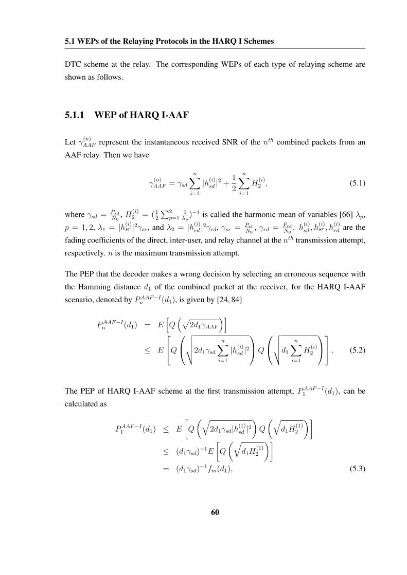
5.1 WEPs of the Relaying Protocols in the HARQ I Schemes
DTC scheme at the relay. The corresponding WEPs of each type of relaying scheme are
shown as follows.
5.1.1 WEP of HARQ I-AAF
Let γ(n)AAF represent the instantaneous received SNR of the nth combined packets from an
AAF relay. Then we have
γ(n)AAF = γsd
n∑i=1
|h(i)sd |2 +
1
2
n∑i=1
H(i)2 , (5.1)
where γsd = Psd
N0, H
(i)2 = (1
2
∑2p=1
1λp
)−1 is called the harmonic mean of variables [66] λp,
p = 1, 2, λ1 = |h(i)sr |2γsr, and λ2 = |h(i)
rd |2γrd, γsr = Psr
N0, γrd = Prd
N0. h
(i)sd , h
(i)sr , h
(i)rd are the
fading coefficients of the direct, inter-user, and relay channel at the nth transmission attempt,
respectively. n is the maximum transmission attempt.
The PEP that the decoder makes a wrong decision by selecting an erroneous sequence with
the Hamming distance d1 of the combined packet at the receiver, for the HARQ I-AAF
scenario, denoted by PAAF−In (d1), is given by [24, 84]
PAAF−In (d1) = E
[Q
(√2d1γAAF
)]
≤ E
Q
√√√√2d1γsd
n∑i=1
|h(i)sd |2
Q
√√√√d1
n∑i=1
H(i)2
. (5.2)
The PEP of HARQ I-AAF scheme at the first transmission attempt, PAAF−I1 (d1), can be
calculated as
PAAF−I1 (d1) ≤ E
[Q
(√2d1γsd|h(1)
sd |2)
Q
(√d1H
(1)2
)]
≤ (d1γsd)−1E
[Q
(√d1H
(1)2
)]
= (d1γsd)−1fm(d1), (5.3)
60
5.1 WEPs of the Relaying Protocols in the HARQ I Schemes
where
fm(d1) = E
[Q
(√d1H
(1)2
)]. (5.4)
The function Q(x) is defined as
Q(x) =1√2π
∫ ∞
x
e−y2/2dy. (5.5)
The closed form expression of fm(d1) can be calculated by using the moment generating
function (MDF) of the Harmonic mean of two exponential random variables [66]. At high
SNR, fm(d1) can be approximated as [39, 68]
fm(d1) =
(1
γsr
+1
γrd
)(d1)
−1. (5.6)
By substituting Eq.(5.6) into Eq.(5.3), we have
PAAF−I1 (d1) ≤ 1
(γsd)
(1
γsr
+1
γrd
)(d1)
−2. (5.7)
Following similar calculations as in Eq.(5.3) to Eq.(5.7), Eq.(5.2) can be further generally
written as
PAAF−In (d1) ≤ 1
(γsd)n
(1
γsr
+1
γrd
)n
(d1)−2n. (5.8)
Let PF,AAF−I represent the average WEP upper bound for combined packets from the direct
and relay channel at the destination in the HARQ I-AAF scheme. Then we have
PF,AAF−I =4l∑
d1=d1,min
A(d1)PAAFn (d1)
=1
(γsd)n
(1
γsr
+1
γrd
)n 4l∑
d1=d1,min
A(d1)1
(d1)2n, (5.9)
61

5.1 WEPs of the Relaying Protocols in the HARQ I Schemes
where A(d1) =∑l
j=1
(lj
)p(d1|j),
(lj
)is the number of words with Hamming weight j and
p(d1|j) is the probability that an input word with Hamming weight j produces a codeword
with Hamming weight d1.
5.1.2 WEP of HARQ I-perfect DTC
Let γ(n)DTC represent the instantaneous received SNR of the nth combined packets from a DAF
relay using perfect DTC, then we have
γ(n)DTC = γsd
n∑i=1
|h(i)sd |2 + γrd
n∑i=1
|h(i)rd |2. (5.10)
The average PEP of incorrectly decoding a combined packet using DTC at the nth transmis-
sion attempt with Hamming weight d, denoted by P(Perfect−I)n (d), can be calculated as
P (Perfect−I)n (d) = E
Q
√√√√2d1γsd
n∑i=1
|h(i)sd |2 + 2d2γrd
n∑i=1
|h(i)rd |2
= E
Q
√√√√2d1γsd
n∑i=1
|h(i)sd |2
Q
√√√√2d2γrd
n∑i=1
|h(i)rd |2
≤ 1
(γsd)n
1
(γrd)n(d1)
−n(d2)−n, (5.11)
where d1 and d2 are the Hamming weights of the erroneous packets with Hamming weight
d, transmitted from the source and relay respectively, such that d = d1 + d2.
Let PF,Perfect−I represent the average WEP upper bound for combined packets from the
direct and relay channels at the destination in the HARQ I-perfect DTC scheme. Then we
have
PF,Perfect−I =4l∑
d=d,min
A(d)P (Perfect)n (d)
=1
(γsd)n
1
(γrd)n
4l∑
d=d,min
A(d)1
(d1)n(d2)n. (5.12)
62

5.1 WEPs of the Relaying Protocols in the HARQ I Schemes
5.1.3 WEP of HARQ I-ARP
The ARP is the combination of AAF and DAF. Therefore, to obtain the WEP of ARP, at first,
we need to calculate the probability of a scenario using either AAF or perfect DTC at the
relay.
Let PF,sr−I(dsr, γsr|h(n)sr ) be the conditional PEP of incorrectly decoding a packet into an-
other packet with Hamming distance of dsr in the inter-user channel at the nth transmission
attempt. Then we have
PF,sr−I(dsr, γsr|h(n)sr ) = Q
√√√√2dsrγsr
n∑i=1
|h(i)sr |2
. (5.13)
Let PF,sr−I(γsr|hsr) represent the conditional WEP in the inter-user channel for the HARQ
I scheme, so
PF,sr−I(γsr|h(n)sr ) =
2l∑
dsr=dsr,min
A(dsr)PF,sr−I(dsr, γsr|h(n)sr )
=1
(γsr)n
2l∑
dsr=dsr,min
A(dsr)(dsr)−n, (5.14)
where dsr,min is the minimum code Hamming distance.
Let P (ARP−I) represent the average PEP at high SNR for the ARP scheme at the relay. At
63

5.1 WEPs of the Relaying Protocols in the HARQ I Schemes
the first transmission attempt, it can be approximated as
P(ARP−I)1 (d)
≤ E{
PF,sr−I(dsr, γsr|h(1)sr )PAAF
1 (d1) +[1− PF,sr−I(dsr, γsr|h(1)
sr )]P
(Perfect)1 (d)
}
≤ E
{PF,sr−I(dsr, γsr|h(1)
sr )Q
(√2d1γsd|h(1)
sd |2)
Q
(√d1H
(1)2
)
+[1− PF,sr−I(dsr, γsr|h(1)
sr )]Q
(√2d1γsd|h(1)
sd |2)
Q
(√2d2γrd|h(1)
rd |2)}
≤ 1
d1γsd
E
{PF,sr−I(dsr, γsr|h(1)
sr )Q
(√d1H
(1)2
)
+[1− PF,sr−I(dsr, γsr|h(1)
sr )]Q
(√2d2γrd|h(1)
rd |2)}
≤ 1
d1γsd
{f(d1) +
(1− 1
γsr
∑2ldsr=dsr,min
A(dsr)1
dsr
d2γrd
)}, (5.15)
where
f(d1) = E
2l∑
dsr=dsr,min
A(dsr)Q
(√2dsrγsr|h(1)
sr |2)
Q
(√d1H
(1)2
) . (5.16)
The calculation of f(d1) in Eq.(5.16) depends on the product of two Q-functions, and both
of them have the relationship with γsr. Therefore, we cannot approximate Q
(√d1H
(1)2
)as
we did in Eq.(5.6). By observing the expression of H(1)2 , we can see that
H(1)2 =
[1
2
(|h(1)sr |2γsr
)−1+
(|h(1)
rd |2γrd
)−1]−1
≈ 2min{|h(1)
sr |2γsr, γrdh(1)rd |2
}. (5.17)
64

5.1 WEPs of the Relaying Protocols in the HARQ I Schemes
By using the above approximation, we can get
f(d1)
≈ E
2l∑
dsr=dsr,min
A(dsr)Q
(√2dsrγsr|h(1)
sr |2)
Q
(√2d1min
{|h(1)
sr |2γsr, γrdh(1)rd |2
})
≤2l∑
dsr=dsr,min
A(dsr)1
γsr
[1
(dsr + d1)+
1
γrddsr(dsr + d1)
]. (5.18)
By substituting Eq.(5.18) into Eq.(5.15), we have Eq.(5.19):
P(ARP−I)1 (d) ≤ 1
d1γsd
2l∑
dsr=dsr,min
A(dsr)1
γsr
[1
(dsr + d1)+
1
γrddsr(dsr + d1)
]
+1− 1
γsr
∑2ldsr=dsr,min
A(dsr)1
dsr
d2γrd
}
=1
d1γsd
1
d2γrd
1 +
γrd
γsr
2l∑
dsr=dsr,min
A(dsr)d2
dsr + d1
. (5.19)
Since the fading coefficients are independent during the retransmission attempts, the PEP of
HARQ I-ARP of the nth transmission can be generally written as
P (ARP−I)n (d) =
1
(γsdγrdd1d2)n
1 +
(γrd
γsr
)n 2l∑
dsr=dsr,min
A(dsr)(d2)
n
(dsr + d1)n
. (5.20)
Then the average WEP upper bound in the HARQ I-ARP scheme can be expressed as
PF,ARP−I ≤4l∑
d=d,min
A(d)P (ARP−I)n (d)
≤ 1
(γsd)n(γrd)n
4l∑
d=d,min
A(d)×
1
(d1)n(d2)n
1 +
(γrd
γsr
)n 2l∑
dsr=dsr,min
A(dsr)(d2)
n
(dsr + d1)n
. (5.21)
65

5.2 WEPs of the Relaying Protocols in the HARQ II Schemes
5.2 WEPs of the Relaying Protocols in the HARQ II Schemes
Compared with the HARQ I schemes, the only difference when calculating the WEP of the
relaying protocols in the HARQ II schemes is the nth combined packet Hamming weight. In
the HARQ I relaying schemes, the transmitter sends the repetition code in each transmission,
so the nth combined codeword Hamming weight is fixed. However, in the HARQ II relaying
schemes, with the transmitted incremental redundancy during the retransmission attempts,
the nth combined packet Hamming weight changes.
5.2.1 WEP of HARQ II-AAF
Following a similar calculation to that in Eq.(5.2), the PEP for HARQ II-AAF, denoted by
PAAF−IIn (d
(n)1 ), is given by
PAAF−IIn (d
(n)1 ) = E
[Q
(√2d
(n)1 γAAF
)]
≤ E
Q
√√√√2γsd
n∑i=1
d(i)1 |h(i)
sd |2 Q
√√√√n∑
i=1
d(i)1 H
(i)2
≤ E
[Q
(√2γsd
((d
(0)1 + d
(1)1 )|h(1)
sd |2 + · · ·+ d(n)1 |h(n)
sd |2))
×
Q
(√(d
(0)1 + d
(1)1 )H
(1)2 + · · ·+ d
(n)1 H
(n)2
)]
≤ 1
(γsd)n
(1
γsr
+1
γrd
)n
(d(0)1 + d
(1)1 )−2 · · · (d(n)
1 )−2, (5.22)
where d(0)1 and d
(1)1 are the Hamming weight of the information symbols and parity symbols
of the first transmitted code C1, d(i)1 is the Hamming weight of incremental redundancy in
the ith transmission. If we assume that the maximum transmission attempts are n, d1 =
d(0)1 + d
(1)1 + · · ·+ d
(n)1 , which is the Hamming weight of the mother code Cm.
66
5.2 WEPs of the Relaying Protocols in the HARQ II Schemes
The average WEP upper bound for the HARQ II-AAF scheme can be expressed as
PF,AAF−II =4l∑
d(n)1 =d
(n)1,min
A(d(n)1 )PAAF−II
n (d(n)1 )
=1
(γsd)n
(1
γsr
+1
γrd
)n 4l∑
d(n)1 =d
(n)1,min
A(d(n)1 )
1
(d(0)1 + d
(1)1 )2 · · · (d(n)
1 )2,(5.23)
where A(d(n)1 ) is the number of codewords with Hamming weight d(n)
1 , d(n)1,min is the combined
packet for the nth previous retransmission attempts.
5.2.2 WEP of HARQ II-perfect DTC
Similarly to that in Eq.(5.11), for perfect DTC used in the HARQ II scheme, the PEP can be
calculated as
P (Perfect−II)n (d(n))
= E
Q
√√√√2γsd
n∑i=1
d(i)1 |h(i)
sd |2 + 2γrd
n∑i=1
d(i)2 |h(i)
rd |2
≤ 1
(γsd)n(γrd)n(d
(0)1 + d
(1)1 )−1 · · · (d(n)
1 )−1(d(0)2 + d
(1)2 )−1 · · · (d(n)
2 )−1. (5.24)
The WEP of perfect DTC used in the HARQ II scheme is given by
PF,Perfect−II (5.25)
=4l∑
d(n)=d(n),min
A(d(n))P (Perfect−II)n (d(n))
=1
(γsd)n(γrd)n
4l∑
d(n)=d(n),min
A(d(n))1[
(d(0)1 + d
(1)1 ) · · · d(n)
1
] [(d
(0)2 + d
(1)2 ) · · · d(n)
2
] .
67

5.2 WEPs of the Relaying Protocols in the HARQ II Schemes
5.2.3 WEP of HARQ II-ARP
In the HARQ II-ARP scheme, the conditional PEP of incorrectly decoding a codeword into
another codeword in the inter-user channel at the nth transmission attempt can be computed
in a similar way to that in Eq.(5.13), so
PF,sr−II(d(n)sr , γsr|h(n)
sr ) = Q
√√√√2γsr
n∑i=1
d(i)sr |h(i)
sr |2 . (5.26)
Furthermore, the average PEP of the HARQ II-ARP scheme, similarly to Eq.(5.19) at high
SNR, is given as
P (ARP−II)n (d(n)) (5.27)
≤ E{
PF,sr−II(d(n)sr , γsr|h(n)
sr )PAAF−IIn (d
(n)1 )
+[1− PF,sr−II(d
(n)sr , γsr|h(n)
sr )]P (Perfect−II)
n (d(n))}
≤ 1[(γsd)n
(d
(0)1 + d
(1)1
)· · · d(n)
1
] [(γrd)n
(d
(0)2 + d
(1)2
)· · · d(n)
2
] ×
1 +
(γrd
γsd
)n 2l∑
d(n)sr =d
(n)sr ,min
A(d(n)sr )
(d
(0)2 + d
(1)2
)· · · d(n)
2[(d
(0)sr + d
(1)sr
)+
(d
(0)1 + d
(1)1
)]· · ·
(d
(n)sr + d
(n)1
) .
Then, the average WEP upper bound for the HARQ II-ARP scheme can be written as
PF,ARP−II (5.28)
≤4l∑
d(n)=d(n),min
A(d(n))P (ARP−II)n (d(n))
≤ 1
(γsd)n(γrd)n
4l∑
d(n)=d(n),min
A(d(n))
1[(d
(0)1 + d
(1)1
)· · · d(n)
1
] [(d
(0)2 + d
(1)2
)· · · d(n)
2
]×
1 +
(γrd
γsr
)n 2l∑
dsr=d(n)sr ,min
A(d(n)sr )
(d
(0)2 + d
(1)2
)· · · d(n)
2[(d
(0)sr + d
(1)sr
)+
(d
(0)1 + d
(1)1
)]· · ·
(d
(n)sr + d
(n)1
)
.
68

5.3 WEPs of the Relaying Protocols in the HARQ III Schemes
5.3 WEPs of the Relaying Protocols in the HARQ III Schemes
As we presented in section 4.3.3, the HARQ III scheme uses the current received packet to
decode, because of its self-decodable property. The receiver only combines all the received
packets together for decoding if the decoding result is not correct. Since each transmitted
packet contains the information symbols and different parity symbols, the Hamming weight
calculation of the combined codes, at the nth transmission attempt, is thus different.
5.3.1 WEP of HARQ III-AAF
Similarly to Eq.(5.22), the PEP for the HARQ III-AAF scheme, denoted by PAAF−IIIn (d
(n)1 ),
can be expressed as
PAAF−IIIn (d
(n)1 )
= E
[Q
(√2d
(n)1 γAAF
)]
≤ E
Q
√√√√2γsd
(n∑
i=1
(d(0)1 + d
(i)1 )|h(i)
sd |2)
Q
√√√√(
n∑i=1
(d(0)1 + d
(i)1 )H i
2
)
≤ 1
(γsd)n
(1
γsr
+1
γrd
)n[
n∏i=1
(d(0)1 + d
(i)1 )
]−2
. (5.29)
The WEP of the HARQ III-AAF is given by
PF,AAF−III
=4l∑
d(n)1 =d
(n)1 ,min
A(d(n)1 )PAAF−III
n (d(n)1 )
=1
(γsd)n
(1
γsr
+1
γrd
)n 4l∑
d(n)1 =d
(n)1 ,min
A(d(n)1 )
1[∏ni=1(d
(0)1 + d
(i)1 )
]2 . (5.30)
69

5.3 WEPs of the Relaying Protocols in the HARQ III Schemes
5.3.2 WEP of HARQ III-perfect DTC
Following a similar analysis to that in Eq.(5.24), for the perfect DTC in the HARQ III
scheme, the PEP can be calculated as
P (Perfect−III)n (d(n))
= E
Q
√√√√2γsd
n∑i=1
d(i)1 |h(i)
sd |2 + 2γrd
n∑i=1
d(i)2 |h(i)
rd |2
≤ 1
(γsd)n(γrd)n
1∏ni=1(d
(0)1 + d
(i)1 )
∏ni=1(d
(0)2 + d
(i)2 )
. (5.31)
The WEP of the perfect-DTC used in the HARQ III scheme, is given by
PF,Perfect−III
=4l∑
d(n)=d(n),min
A(d(n))P (Perfect−III)n (d(n))
=1
(γsd)n(γrd)n
4l∑
d(n)=d(n),min
A(d(n))1∏n
i=1(d(0)1 + d
(i)1 )
∏ni=1(d
(0)2 + d
(i)2 )
. (5.32)
5.3.3 WEP of HARQ III-ARP
Following a similar analysis to that in Eq.(5.27), the average PEP of the HARQ III-ARP
scheme at high SNR is given as
P (ARP−III)n (d(n))
≤ E{
PF,sr−III(d(n)sr , γsr|h(n)
sr )PAAF−IIIn (d
(n)1 )
+[1− PF,sr−III(d
(n)sr , γsr|h(n)
sr )]P (Perfect−III)
n (d(n))}
≤ 1[(γsd)n
∏ni=1
(d
(0)1 + d
(i)1
)] [(γrd)n
∏ni=1
(d
(0)2 + d
(i)2
)] ×
1 +
(γrd
γsd
)n 2l∑
d(n)sr =d
(n)sr ,min
A(d(n)sr )
∏ni=1
(d
(0)2 + d
(i)2
)
∏ni=1
[(d
(0)sr + d
(i)sr
)+
(d
(0)1 + d
(i)1
)] .(5.33)
70

5.4 Throughput Analysis
Then, the average WEP upper bound for the HARQ III-ARP scheme can be written as
PF,ARP−III
≤4l∑
d(n)=d(n),min
A(d(n))P (ARP−III)n (d(n))
≤ 1
(γsd)n(γrd)n
4l∑
d(n)=d(n),min
A(d(n))
1[∏ni=1
(d
(0)1 + d
(i)1
)] [∏ni=1
(d
(0)2 + d
(i)2
)]×
1 +
(γrd
γsr
)n 2l∑
dsr=d(n)sr ,min
A(d(n)sr )
∏ni=1
(d
(0)2 + d
(i)2
)
∏ni=1
[(d
(0)sr + d
(i)sr
)+
(d
(0)1 + d
(i)1
)]
. (5.34)
5.4 Throughput Analysis
In this section, we analyze the throughput of various HARQ schemes. The average through-
put, denoted by RAV can be calculated as in [11, 13],
RAV =P
P + lav
k
k + nc + m(5.35)
where lav is the average number of additional transmitted symbols per P information sym-
bols, k is the number of information symbols, nc is the length of CRC check symbols for
error detection, and m is the number of tail symbols. The factor k/(k + nc + m) is the loss
in the throughput due to the added parity symbols for error detection and the tail symbols to
each transmitted packet.
Eq.(5.35) applies to all the HARQ schemes, including the HARQI (repetition coding), HAR-
QII and HARQIII (incremental redundancy) schemes. In this thesis, the source and relay use
same code rate during each transmission. Therefore, the length of each transmitted packet
is the same. Let Pi denote the average number of additional transmitted symbols for each
transmission attempt, and let PF
(i)SD
, PF
(i)com
denote the probability of the decoded combined
packets from direct channel containing errors, and the decoded combined packets from di-
rect and relay channels containing errors, at the ith transmission attempt, i = 1, 2, · · · , n,
71

5.4 Throughput Analysis
respectively. Clearly, with the HARQ relaying schemes, in general, we have lav
lav = P1+P1PF(1)SD
+P2PF(1)com
+· · ·+PiPF(i)SD
+Pi+1PF(i)com
+· · ·+Pn−1PF(n−1)SD
+PnPF
(n−1)com
,
(5.36)
where PF
(i)com
can be expressed for the three types of HARQ schemes, given by Eqs.(5.9),
(5.23) and (5.30) for the HARQ-AAF scheme, by Eqs.(5.12), (5.25) and (5.32) for the
HARQ-perfect DTC scheme and by Eqs.(5.21), (5.28) and (5.34) for the HARQ-ARP scheme,
respectively.
The term PF
(i)SD
can be calculated similarly to that in Eq.(5.2) or in Eq.(5.11), depending on
the relaying protocols. For example, in the HARQI schemes, the general expression of PF
(n)SD
for the HARQ-AAF scheme is given by
PF
(n)SD ,AAF−I
≤ E
Q
√√√√2d1γsd
n∑i=1
|h(i)sd |2
Q
(√d1H
(n−1)2
)
≤ 1
(γsd)n(γrd)n−1
4l∑
d1=d1,min
A(d1)1
(d1)(2n−1)
{1 + (
γrd
γsr
)n−1
}. (5.37)
In the HARQI perfect-DTC scheme, PF
(n)SD
is given by
PF
(n)SD ,P erfect−I
≤ E
Q
√√√√2d1γsd
n∑i=1
|h(i)sd |2
Q
√√√√2d2γrd
n−1∑i=1
|h(i)rd |2
≤ 1
(γsd)n(γrd)(n−1)
4l∑
d=d,min
A(d)1
(d1)n(d2)(n−1). (5.38)
Following a similar calculation to that in Eq.(5.15), the PF
(n)SD ,ARP−I
in HARQI-ARP can be
72

5.4 Throughput Analysis
expressed as
PF
(n)SD ,ARP−I
≤ E
PF,sr−I(dsr, γsr|h(i)
sr )Q
√√√√2d1γsd
n∑i=1
|h(i)sd |2 + d1H
(n−1)2
+[1− PF,sr−I(dsr, γsr|h(i)
sr )]Q
√√√√2d1γsd
n∑i=1
|h(i)sd |2 + 2d2γrd
n−1∑i=1
|h(i)rd |2
≤ 1
(γsd)n(γrd)n−1
4l∑
d=d,min
A(d)1
(d1)n(d2)n−1
{1 +
(γrd
γsr
)n−1
×
2l∑
dsr=dsr,min
A(dsr)(d2)
n−1
(dsr + d1)n−1
. (5.39)
Therefore, the PF
(i)SD
for three types of HARQ schemes, can be generally expressed as fol-
lows:
PF
(n)SD ,AAF−p
=1
(γsd)n(γrd)n−1
4l∑
d1=d(n)1,min
A(d1){
θ(γ)D′p
}, (5.40)
PF
(n)SD ,P erfect−p
=1
(γsd)n(γrd)n−1
4l∑
d=d(n),min
A(d)Dp, (5.41)
PF
(n)SD ,ARP−p
=1
(γsd)n(γrd)n−1
4l∑
d=d(n),min
A(d) {θ(γ)DpSp} , (5.42)
where D′p in Eq.(5.44), Dp in Eq.(5.45), and Sp in Eq.(5.46) represent the coefficients for
the above PF
(i)SD
expressions, p represents the protocol type number, denoted by I, II and III,
respectively; and
θ(γ) = 1 +
(γrd
γsr
)n−1
, (5.43)
73

5.5 Performance Comparison between HARQ-ARP and HARQ-perfect DTC
D′I =
1
(d1)2n−1
D′II =
1[(d
(0)1 + d
(1)1 · · · d(n)
1
)] [(d
(0)1 + d
(1)1 · · · d(n−1)
1
)]
D′III =
1[∏ni=1
(d
(0)1 + d
(i)1
)] [∏n−1i=1
(d
(0)1 + d
(i)1
)] , (5.44)
DI =1
(d1)n(d2)n−1
DII =1[(
d(0)1 + d
(1)1 · · · d(n)
1
)] [(d
(0)2 + d
(1)2 · · · d(n−1)
2
)]
DIII =1[∏n
i=1
(d
(0)1 + d
(i)1
)] [∏n−1i=1
(d
(0)2 + d
(i)2
)] , (5.45)
SI =
2l∑
dsr=dsr,min
A(dsr)(d2)
n−1
(dsr + d1)n−1
SII =
2l∑
dsr=d(n−1)sr,min
A(d(n−1)sr )
(d
(0)2 + d
(1)2
)· · · d(n−1)
2[(d
(0)sr + d
(1)sr
)+
(d
(0)1 + d
(1)1
)]· · ·
(d
(n−1)sr + d
(n−1)1
)
SIII =
2l∑
dsr=d(n−1)sr,min
A(d(n−1)sr )
∏n−1i=1
(d
(0)2 + d
(i)2
)
∏n−1i=1
[(d
(0)sr + d
(i)sr
)+
(d
(0)1 + d
(i)1
)]
. (5.46)
Substituting Eq.(5.36) into Eq.(5.35), we can obtain the average throughput expression.
5.5 Performance Comparison between HARQ-ARP and HARQ-
perfect DTC
In this thesis, we apply the same code to all HARQ relaying schemes, so the code distance
spectrum is fixed during the comparison.
74

5.5 Performance Comparison between HARQ-ARP and HARQ-perfect DTC
To evaluate the performance between HARQ-ARP and HARQ-perfect DTC, we need to in-
vestigate the expression PF
(i)com
and PF
(i)SD
for various HARQ schemes. To make this compar-
ison clear and easy to follow, first we give the general expression of WEPs for three types of
HARQ-ARP by Eqs.(5.21), (5.28) and (5.34) and HARQ-perfect DTC by Eqs.(5.12), (5.25)
and (5.32)
PF,ARP−p =1
(γsd)n(γrd)n
4l∑
d(n)=d(n),min
A(d(n))CpRp, (5.47)
PF,Perfect−p =1
(γsd)n(γrd)n
4l∑
d(n)=d(n),min
A(d(n))Cp, (5.48)
where Cp in Eq.(5.49) and Rp in Eq.(5.50) represent the coefficients for the above WEP
expressions.
CI =1
(d1)n(d2)n
CII =1[
(d(0)1 + d
(1)1 ) · · · (d(n)
1 )] [
(d(0)2 + d
(1)2 ) · · · (d(n)
2 )]
CIII =1[∏n
i=1(d(0)1 + d
(i)1 )
] [∏ni=1(d
(0)2 + d
(i)2 )
] , (5.49)
RI =
1 +
(γrd
γsr
)n 2l∑
dsr=dsr,min
A(dsr)(d2)
n
(dsr + d1)n
RII =
1 +
(γrd
γsr
)n 2l∑
dsr=d(n)sr ,min
A(d(n)sr )
(d
(0)2 + d
(1)2
)· · · d(n)
2[(d
(0)sr + d
(1)sr
)+
(d
(0)1 + d
(1)1
)]· · ·
(d
(n)sr + d
(n)1
)
RIII =
1 +
(γrd
γsr
)n 2l∑
dsr=d(n)sr ,min
A(d(n)sr )
∏ni=1
(d
(0)2 + d
(i)2
)
∏ni=1
[(d
(0)sr + d
(i)sr
)+
(d
(0)1 + d
(i)1
)] . (5.50)
Clearly, for the HARQ-ARP scheme, the FER expression of the unsuccessful decoding at
75
5.6 Performance Comparison between HARQ-ARP and HARQ-AAF
the destination at the nth transmission attempt is
P(n)FER,ARP = P
(1)SD,ARP−pP
(1)F,ARP−p · · ·P (n)
SD,ARP−pP(n)F,ARP−p
=n∏
i=1
P(i)SD,ARP−p
n∏i=1
P(i)F,ARP−p. (5.51)
For the HARQ-perfect DTC scheme, the FER expression can be similarly expressed as
P(n)FER,Perfect =
n∏i=1
P(i)SD,Perfect−p
n∏i=1
P(i)F,Perfect−p. (5.52)
Since the additional transmitted symbols for each transmission attempt Pi, and the probabil-
ity of decoding a packet in the first transmission from the direct channel PF
(1)SD
in Eq.(5.36) are
the same for both schemes, we only need to study the expression P(i)F,ARP−p and P
(i)F,Perfect−p,
i = 1, 2, · · · , n for the HARQ-ARP by Eq.(5.47) and HARQ-perfect DTC schemes by
Eq.(5.48), respectively; and P(i)SD, i = 2, · · · , n given by Eq.(5.41) for the HARQ-perfect
DTC scheme and Eq.(5.42) for the HARQ-ARP, respectively.
It can be noted that as γsr increases, (γrd
γsr) → 0, Sp in Eq.(5.46) and Rp in Eq.(5.50) approach
one, so the value of the P(i)F,ARP−p in Eq.(5.47) and P
F(i)SD,ARP−p
in Eq.(5.42) approach the
value of the P(i)F,Perfect−p in Eq.(5.48) and P
F(i)SD,Perfect−p
in Eq.(5.41), respectively.
As each item in Eqs.(5.51) and (5.52) has the same relationship, we conclude that the per-
formance of HARQ-ARP approaches HARQ-perfect DTC in the high γsr region.
5.6 Performance Comparison between HARQ-ARP and HARQ-
AAF
In this section, we compare the performance between HARQ-ARP and HARQ-AAF. In order
to analyze their performance, we can follow a similar analysis in section 5.5. The HARQ-
ARP is based on a DTC scheme, and we need to evaluate its distance spectrum, which
makes the analysis and comparison complicated and more difficult. However, it is well
76

5.6 Performance Comparison between HARQ-ARP and HARQ-AAF
known that the turbo codes outperform convolutional codes at medium to high SNRs [45].
We also observed that both HARQ-AAF and HARQ-ARP with a DAF scheme (the relay
fully decodes the received signal, re-encodes and forwards it to the destination) are based
on convolutional codes, and it is easy to compare the performance of these two schemes.
Motivated by this, in this thesis, we compare the performance of the HARQ-ARP with a
DAF scheme and the HARQ-AAF scheme.
We will demonstrate that the performance of HARQ-ARP with a DAF scheme is superior to
the HARQ-AAF scheme. As a result, the HARQ-ARP with a DTC scheme exhibits better
performance than the HARQ-AAF scheme. For the HARQ-ARP with a DAF scheme, the
signals transmitted from the source and relay are the same codes, so their Hamming weights
of the erroneous packets are the same. Therefore, following the similar WEP calculations
that we used for the ARP-DTC scheme in Eqs.(5.21), (5.28), and (5.34), the WEP of ARP-
DAF for each type of HARQ scheme can be generally calculated as
PF,ARPDAF−p =
1
(γsd)n(γrd)n
4l∑
d1=d(n)1 ,min
A(d1)C′p
{1 +
(γrd
γsr
)n
R′p
}, (5.53)
where R′p in Eq.(5.53) can be expressed as in Eq.(5.54)
R′I =
2l∑
dsr=dsr,min
A(dsr)(d1)
n
(dsr + d1)n
R′II =
2l∑
dsr=d(n)sr ,min
A(d(n)sr )
(d
(0)1 + d
(1)1
)· · · d(n)
1[(d
(0)sr + d
(1)sr
)+
(d
(0)1 + d
(1)1
)]· · ·
(d
(n)sr + d
(n)1
)
R′III =
2l∑
dsr=d(n)sr ,min
A(d(n)sr )
∏ni=1
(d
(0)1 + d
(i)1
)
∏ni=1
[(d
(0)sr + d
(i)sr
)+
(d
(0)1 + d
(i)1
)] , (5.54)
and the PF
(i)SD
for the HARQ ARP-DAF schemes is given by
PF
(n)SD ,ARP
DAF−p=
1
(γsd)n(γrd)n−1
4l∑
d1=d(n)1 ,min
A(d){
θ(γ)D′pS
′p
}, (5.55)
77

5.6 Performance Comparison between HARQ-ARP and HARQ-AAF
where
S′I =
2l∑
dsr=dsr,min
A(dsr)(d1)
n−1
(dsr + d1)n−1
S′II =
2l∑
dsr=d(n−1)sr,min
A(d(n−1)sr )
(d
(0)1 + d
(1)1
)· · · d(n−1)
1[(d
(0)sr + d
(1)sr
)+
(d
(0)1 + d
(1)1
)]· · ·
(d
(n−1)sr + d
(n−1)1
)
S′III =
2l∑
dsr=d(n−1)sr,min
A(d(n−1)sr )
∏n−1i=1
(d
(0)1 + d
(i)1
)
∏n−1i=1
[(d
(0)sr + d
(i)sr
)+
(d
(0)1 + d
(i)1
)]
. (5.56)
In addition, the general expression of the HARQ-AAF schemes by Eqs.(5.9), (5.23) and
(5.30), can be written as
PF,AAF−p =1
(γsd)n(γrd)n
4l∑
d1=d(n)1 ,min
A(d1)C′p.
{1 +
(γrd
γsr
)n}. (5.57)
Following a similar analysis to that in section 5.5, the FER expressions for the HARQ ARP-
DAF and HARQ-AAF schemes are given by
P(n)
FER,ARPDAF
=n∏
i=1
PF
(i)SD,ARP
DAF−p
n∏i=1
P(i)
F,ARPDAF−p
. (5.58)
P(n)FER,AAF =
n∏i=1
P(i)SD,AAF−p
n∏i=1
P(i)F,AAF−p. (5.59)
Since R′p ≤ 1 and S
′p ≤ 1 , which have been proved in Appendix B, by comparing PF,ARP
DAF−p
in Eq.(5.53) with PF,AAF−p in Eq.(5.57) and PF
(n)SD ,AAF−p
in Eq.(5.40) with PF
(n)SD ,ARP
DAF−pin
Eq.(5.55), it is obvious that PF,ARPDAF−p ≤ PF,AAF−p and P
F(n)SD ,AAF−p
≤ PF
(n)SD ,ARP
DAF−pfor each
item in the above two FER expressions. So the ARP-DAF can achieve a smaller error rate
78

5.7 Simulation Results
compared to AAF under the same γsr and γrd values, such as
P(n)
FER,ARPDAF
≤ P(n)FER,AAF . (5.60)
Furthermore, the PF,ARPDTC
and PF,AAFhave a similar relationship:
P(n)
FER,ARPDTC
≤ P(n)FER,AAF . (5.61)
From the above analysis, it has been shown that the HARQ-ARP with DTC performs better
than the HARQ-AAF.
5.7 Simulation Results
In this section, we present the performance comparison for various HARQ schemes. In all
simulations, data are grouped into a frame of length 130 symbols, including 16 CRC check
symbols and 2 tail symbols. A four-state rate 1/2 RSC code with generators (5, 7)8 is used
with BPSK modulation. At the receiver, a soft output Viterbi algorithm (SOVA)/Viterbi
algorithm (VA) decoder is used. The maximum retransmission number is set to n = 3 and
the maximum number of iterations is set to 8. The direct and relay channels have the same
SNR, which varies from 0 to 14 dB, while the inter-user channel is variable from 0 to 24 dB.
In order to present equitable comparisons, we apply the persistent transmission principle at
the relay. Since the relay always transmits in the HARQ AAF and HARQ ARP-DAF/DTC
schemes, so the relay in the HARQ DAF-DTC scheme transmits even though the received
packet from the source is decoded in error.
Fig. 5.1 compares the FER results obtained by the analysis developed in this thesis and
simulations. The FER results are presented for the HARQ I-perfect DTC scheme, which is
used as the performance lower bound for the proposed HARQ I-ARP scheme. The analytical
FER results are calculated for the first term in the bound sum in Eq.(5.48), and for asymptotic
values of γsd, γrd, for which the number of paths∑4l
d(n)=d(n),min A(d(n)) has not a big effect
on the performance and thus was assumed to be 1. The two curves have the same slope
79

5.7 Simulation Results
and the match could be improved by calculating the coefficient∑4l
d(n)=d(n),min A(d(n)) and
including more levels from the expression in Eq.(5.48).
Fig. 5.2 shows the FER comparison of various HARQ I schemes. As an example, it is shown
that the ARP-DAF outperforms the AAF in the whole γrd region, and the performance of the
ARP-DTC is much better than the ARP-DAF due to an addtional coding gain with the DTC
structure. The simulation results also prove our analysis in section 5.5, that is, the ARP-DTC
scheme can achieve a high error rate reduction compared to AAF under the same γsr and γrd
values. In addition, we can see from Eqs.(5.42) and (5.47) that as γsr increases, θγSp and
Cp come close to one. So P(n)FER,ARP → P
(n)FER,Perfect, thus the ARP-DTC approaches the
perfect DTC scheme. This trend can be noticed from the simulation results shown in these
two figures.
Figs. 5.3, 5.4, 5.5 and 5.6 compare the FER performance of various HARQ II and HARQ
III schemes with the two RCPT families we introduced in sections 4.3.2 and 4.3.3. Similar
to the HARQ I scheme, the ARP-DTC’s performance is significantly better than the AAF’s
performance in the whole γrd region. When the γsr increases, the FER of ARP-DTC comes
close to the perfect DTC as well.
Figs. 5.7, 5.8, 5.9 and 5.10 show the throughput performance of the HARQ I, HARQ II
and HARQ III schemes with 8 and 24 dB of the inter-user channel. The simulation results
confirm our performance analysis in sections 5.5 and 5.6. We can see that the ARP with
DTC scheme provides a better throughput than the AAF scheme. The throughput increases
as the γsd increases, and as the γsr increases to 24 dB, the performance of ARP-DTC tends
to reach the perfect-DTC.
Fig. 5.11 compares the throughput of various HARQ ARP-DTC schemes. In a relatively
high SNR range, the destination can correctly decode the highest rate packets at the first
transmission and thus reduce the number of retransmissions. Therefore, the HARQ II ARP-
DTC achieves a higher throughput efficiency than the other HARQ ARP-DTC schemes.
Also, the throughput of the HARQ III ARP-DTC scheme is better than that of the HARQ I
ARP-DTC scheme. This is because in the type III scheme the packet with punctured symbols
is transmitted, which reduces the total symbols of transmission. However, at low SNRs, in
the range of 0-4 dB, the HARQ I ARP-DTC scheme outperforms the other two schemes, due
to its high SNR gain.
80

5.7 Simulation Results
Figure 5.1: Comparisons between FER performance based on analysis and simulations forHARQ I-perfect DTC, which is used as the performance lower bound for the proposedHARQ I-ARP scheme
Figure 5.2: FER comparison of HARQ I AAF, HARQ I perfect-DTC, HARQ I ARP-DAFand HARQ I ARP-DTC schemes in a quasi-static fading channel with SNR 8 dB and 24 dBof the inter-user channel
81

5.7 Simulation Results
Figure 5.3: FER comparison of HARQ II AAF, HARQ II perfect-DTC, and HARQ II ARP-DTC schemes in a quasi-static fading channel with SNR 8 dB and 24 dB of the inter-userchannel; the puncturing rates for the first transmission are 4/5
Figure 5.4: FER comparison of HARQ II AAF, HARQ II perfect-DTC, and HARQ II ARP-DTC schemes in a quasi-static fading channel with SNR 8 dB and 24 dB of the inter-userchannel; the puncturing rates for the first transmission are 2/3
82

5.7 Simulation Results
Figure 5.5: FER comparison of HARQ III AAF, HARQ III perfect-DTC, and HARQ IIIARP-DTC schemes in a quasi-static fading channel with SNR 8 dB and 24 dB of the inter-user channel; the puncturing rates for the first transmission are 4/5
Figure 5.6: FER comparison of HARQ III AAF, HARQ III perfect-DTC, and HARQ IIIARP-DTC schemes in a quasi-static fading channel with SNR 8 dB and 24 dB of the inter-user channel; the puncturing rates for the first transmission are 2/3
83

5.7 Simulation Results
Figure 5.7: Throughput comparison of HARQ I AAF, HARQ I perfect-DTC, HARQ I ARP-DAF and HARQ I ARP-DTC schemes in a quasi-static fading channel with SNR 8 dB of theinter-user channel
Figure 5.8: Throughput comparison of HARQ I AAF, HARQ I perfect-DTC, HARQ I ARP-DAF and HARQ I ARP-DTC schemes in a quasi-static fading channel with SNR 24 dB ofthe inter-user channel
84

5.7 Simulation Results
Figure 5.9: Throughput comparison of HARQ II AAF, HARQ II perfect-DTC, and HARQII ARP-DTC schemes in a quasi-static fading channel with SNR 8 dB and 24 dB of theinter-user channel; the puncturing rates for the first transmission are 4/5
Figure 5.10: Throughput comparison of HARQ III AAF, HARQ III perfect-DTC, and HARQIII ARP-DTC schemes in a quasi-static fading channel with SNR 8 dB and 24 dB of the inter-user channel; the puncturing rates for the first transmission are 4/5
85

5.8 Conclusion
Figure 5.11: Throughput comparison of HARQ ARP schemes in a quasi-static fading chan-nel with SNR 24 dB of the inter-user channel; the puncturing rates for the first transmissionare 4/5
5.8 Conclusion
In this chapter, we investigated the performance of three types of HARQ ARP schemes.
The exact WEPs for HARQ AAF, HARQ perfect-DTC and HARQ ARP were derived and
the general throughput expression of each relaying scheme was developed. Based on the
analysis, it was shown that each type of HARQ ARP outperforms the HARQ AAF in the
whole γrd region, due to the contribution of the turbo coding gain. As the γsr increases with
the inter-user channel, the performance of the HARQ ARP approaches the HARQ perfect-
DTC scheme. In addition, we showed, from the throughput comparison of the three types
of HARQ ARP schemes, that the HARQ II ARP achieved higher throughput in a relatively
higher SNR range.
86

Chapter 6
Conclusions
This thesis has studied collaborative HARQ schemes for the cooperative wireless networks.
The main goals were to provide a better understanding of HARQ protocols used in the co-
operative communication systems and develop a robust HARQ scheme by using an adaptive
relaying protocol and distributed coding scheme.
Chapters 1, 2 and 3 provided the background knowledge. Specifically, Chapter 1 gave a
broad overview of the research field, aiming to explain the goals of this work and outline
the remaining chapters. Chapter 2 covered the basic elements of a digital communication
system, fading channels, classic error control coding schemes as well as associated decoding
algorithms. Chapter 3 introduced the knowledge of the cooperative communications. We
reviewed the various relaying protocols used in the cooperative diversity (CD) communica-
tion systems, including amplify and forward (AAF), decode and forward (DAF), selection
relaying and incremental relaying protocols.
Chapter 4 presented our proposed collaborative HARQ strategies for the CD communication
systems. An adaptive relaying protocol (ARP) was proposed and was used together with
type I, II, and III HARQs. The proposed ARP takes merits of the fixed relaying protocols and
avoids their disadvantages. By using distributed coding scheme in the proposed scheme, we
improved the reliability of the systems through not only diversity benefit but also a coding
advantage. The simulation results indicated that the proposed HARQ with ARP (HARQ-
ARP) scheme outperforms the reference HARQ schemes in all SNR regions by 1 ∼ 6 dB.

6.1 Future Work
Chapter 5 provided the performance analysis of the proposed HARQ-ARP scheme. We an-
alyzed the performance of the HARQ relaying schemes by two figures of merit: the average
throughput RAV and frame error rate (FER). We derived the pairwise error probabilities
(PEP) and word error probabilities (WEP) of the HARQ with AAF (HARQ-AAF), HARQ
with perfect distributed turbo codes (HARQ-perfect DTC) and HARQ-ARP schemes. Based
on the derived PEPs and WEPs for each scheme, we obtained a general throughput ex-
pression, which can be used for any of these schemes. In addition, we derived a general
FER expression for the collaborative HARQ systems and used it to compare between the
proposed HARQ-ARP scheme and the reference schemes. The theoretical analysis is vali-
dated through simulations. The analytical and simulation results show that the HARQ-ARP
scheme achieves better performance than HARQ-AAF scheme. As the quality of the inter-
user channel is improved, the performance of HARQ-ARP approaches the HARQ-perfect
DTC scheme.
6.1 Future Work
In this thesis, we only consider a single relay network. In practical systems, there might be a
number of relays between the source and destination. To the best of our knowledge, no gen-
eral framework for designing collaborative HARQ protocols for multi-hop relay networks
has been developed. The design of collaborative HARQ schemes includes several elements,
such as, component codes design, optimal puncturing pattern, path selection and power allo-
cation. They can be optimized by using union bound and code distance spectra. This presents
a big challenge and will be a promising topic to be considered in future research.
In addition, most existing research in HARQ has considered an incremental redundancy (IR)
scheme to provide a lower code rate and a higher throughput. Although the use of an IR
scheme is a promising solution to achieve a higher throughput, its decoding is very complex.
The complexity of such a decoding grows at least as O(k/R), where k is the information
bits and R is the rate of the low rate code [85]. Luby [86] circumvented this problem by
designing rateless codes, also known as Luby Transform (LT) codes, which are not obtained
by puncturing standard block codes. Unlike conventional codes, LT codes encode and trans-
mit the source information in an infinitely long codestream. The codes have the special
property that a receiver can recover the original information from unordered subsets of the
88

6.1 Future Work
codestream, once the total obtained mutual information from multiple sources marginally
exceeds the entropy of the source information. LT codes have been suggested for use in sin-
gle relay links [87, 88], and broadcast and multicast applications [89] in wireless networks,
however, their use in cooperative multi-relay wireless networks has not been analyzed yet.
Therefore, it would also be worth investigating the performance of the LT codes on a multi-
hop CD communication system.
89

Appendix A
The Derivation of Eq. (5.18)
To simplify the calculation, we use x to denote γsr|hsr|2, y to denote γrd|hrd|2, respectively.
The pdf of x and y can be calculated as [33]
p(x) =1
γsr
e−xγsr , (A.1)
p(y) =1
γrd
e−yγrd , (A.2)
f(d1) ≈ E
2l∑
dsr=dsr,min
A(dsr)Q(√
2dsrγsr|hsr|2)
Q(√
2d1min{|hsr|2γsr, γrd|hrd|2})
= E
2l∑
dsr=dsr,min
A(dsr)ϕ(d1)
,
(A.3)

where
ϕ(d1) ≤∫ ∞
0
∫ y
0
Q(√
2dsrx)
Q(√
2d1x)
p(x)d(x)p(y)dy
+
∫ ∞
0
∫ x
0
Q(√
2dsrx)
Q(√
2d1y)
p(y)d(y)p(x)dx
≤∫ ∞
0
∫ y
0
e(−dsrx)e(−d1x) 1
γsr
e−xγsr dxp(y)dy +
∫ ∞
0
∫ x
0
e(−dsrx)e(−d1y) 1
γrd
e−yγrd dyp(x)dx
≤ 1
γsr
∫ ∞
0
∫ y
0
e
h−“dsr+d1+ 1
γrd
”xidxp(y)dy +
1
γrd
∫ ∞
0
e(−dsrx)
∫ x
0
e
h−“d1+ 1
γrd
”yidyp(x)dx
≤ 1
γsr
∫ ∞
0
−1
dsr + d1 + 1γrd
e
h−“dsr+d1+ 1
γrd
”xiy0p(y)dy
+1
γrd
∫ ∞
0
e−ax
−γrde
−“d1+ 1
γrd
”y
1 + d1γrd
x
0
p(x)dx
≤ 1
γsr
∫ ∞
0
−1
dsr + d1 + 1γsr
[(e−(dsr+d1+ 1
γsr)y − 1
) 1
γrd
e−yγrd dy
]
+1
γrd
∫ ∞
0
e−ax
( −γrd
1 + d1γrd
)[e−“d1+ 1
γrd
”x − 1
]1
γrd
e−xγsr dx
≤ 1
γsrγrd
[−1
dsr + d1 + 1γsr
(−1
dsr + d1 + 1γsr
+ 1γrd
1
e
“dsr+d1+ 1
γsr+ 1
γrd
”y
+ γrde−yγrd
)]∞
0
+1
γsrγrd
[−γrd
1 + d1γrd
(−1
dsr + d1 + 1γsr
+ 1γrd
)1
e
“dsr+d1+ 1
γsr+ 1
γrd
”x
+1
dsr + 1γsr
1
e(dsr+ 1γsr
)
]∞
0
≤ 1
γsrγrd
(dsr + d1 + 1
γsr
)γrd(
dsr + d1 + 1γsr
)(dsr + d1 + 1
γsr+ 1
γrd
)
+1
γsrγrd
−γrd
1 + d1γrd
−(d1 + 1
γrd
)(dsr + d1 + 1
γsr+ 1
γrd
)(dsr + 1
γsr
)
≤ 1
γsr
(1
dsr + d1
)+
1
γsrγrddsr
(1
dsr + d1
). (A.4)
By substituting the result of Eq.(A.4) into Eq.(A.3), we can obtain the final result as in
91

Eq.(5.18),
f(d1) ≈ E
2l∑
dsr=dsr,min
A(dsr)1
γsr
[1
(dsr + d1)+
1
dsrγrd (d1 + dsr)
] . (A.5)
92

Appendix B
Proof of Inequality (5.54)
In this section, we only show the proof of inequality of R′1−I at the first transmission attempt
in the HARQI scheme. The nth transmission expressions of R′1, R
′2 and R
′3 in HARQI,
HARQII and HARQIII schemes can be proved in a similar way.
As shown in Eq.(5.14), P(1)F,sr−I represents the conditional WEP in the inter-user channel at
the first transmission attempt, therefore, we have
P(1)F,sr−I =
2l∑
dsr=dsr,min
A(dsr)E
[Q
(√2dsrγsr|h(1)
sr |2)]
≤ 1. (B.1)
Then we arrive at
P(1)F,sr−IQ
(√2d1γsr|h(1)
sr |2)≤ Q
(√2d1γsr|h(1)
sr |2)
. (B.2)
To simplify the calculation, we still use x denote γsr|hsr|2. By averaging the above inequality

with regard to |hsr|2, we get
∫ ∞
0
2l∑
dsr=dsr,min
A(dsr)Q(√
2dsrx)
Q(√
2d1x)
≤∫ ∞
0
Q(√
2d1x)
⇒∫ ∞
0
2l∑
dsr=dsr,min
A(dsr)(e−dsrx)(e−d1x)
1
γsr
(e−x
γsr )dx ≤∫ ∞
0
(e−d1x)1
γsr
(e−x
γsr )dx
⇒2l∑
dsr=dsr,min
A(dsr)1
dsr + d1
≤ 1
d1
⇒2l∑
dsr=dsr,min
A(dsr)d1
dsr + d1
≤ 1. (B.3)
Therefore, we have R′1−I ≤ 1.
94

Bibliography
[1] Z. Zvonar, P. Jung and K. Kammerlander, GSM: Evolution Towards 3rd Generation
Systems. Boston: Kluwer Academic Publishers, 1999.
[2] S. Frattasi, H. Fathi, F. H. P. Fitzek, R. Prasad and M. D. Katz, “Defining 4G technology
from the users perspective,” IEEE Network, vol. 20, no. 1, pp. 35–41, Jan. 2006.
[3] S. Frattasi, H. Fathi, F. H. P. Fitzek, K. Chung and R. Prasad, “4G: The user-centric
system,” Mobile e-Conference (Me), Electronic Conference, Aug. 2004.
[4] S. Frattasi, H. Fathi, F. H. P. Fitzek, M. D. Katz and R. Prasad, “A pragmatic method-
ology to design 4G: from the user to the technology,” in Proc. IEEE ICN’05, Reunion
Island, France, Apr. 2005, pp. 17–21.
[5] C. E. Shannon, “A mathematical theory of communication,” Bell Syst. Tech. J., vol. 27,
pp. 379–423, Oct. 1948.
[6] C. Berrou and A. Glavieux, “Near optimum error correcting coding and decoding:
turbo-codes,” IEEE Trans. Commun., vol. 44, no. 10, pp. 1261–1271, Oct. 1996.
[7] S. Lin and D. J. Costello, Error Control Coding Fundamentals and Applications,
2nd ed. Upper Saddle River, New Jersey: Prentice Hall, 2004.
[8] S. Lin, D. J. Costello and M. Miller, “Automatic-Repeat-Request error-control
schemes,” IEEE Commun. Mag., vol. 22, no. 12, pp. 5–17, Dec. 1984.
[9] S. Lin and P. Yu, “A hybrid ARQ scheme with parity retransmission for error control
of satellite channels,” IEEE Trans. Commun., vol. 7, no. COM-30, pp. 1701–1719, Jul.
1982.

BIBLIOGRAPHY
[10] E. Y. Rocher and R. L. Pickholtz, “An analysis of the effectiveness of hybrid trans-
mission schemes,” IEEE Trans. Commun., vol. IBM J. Res. Dev., no. COM-30, pp.
426–433, Jul. 1970.
[11] J. Hagenauer, “Rate-compatible punctured convolutional codes (RCPC Codes) and
their applications,” IEEE Trans. Commun., vol. 36, no. 4, pp. 389–400, Apr. 1998.
[12] K. R. Narayanan and G. L. Stuber, “A novel ARQ technique using the turbo coding
principle,” IEEE Commun. Lett., vol. 1, no. 2, pp. 49–51, Mar. 1997.
[13] D. Rowitch and L. Milstein, “Rate compatible punctured turbo (RCPT) codes in a hy-
brid FEC/ARQ system,” in Proc. IEEE Globecom’97, Nov. 1997, pp. 55–59.
[14] M. R. D. Rodrigues, I. Chatzigeorgiou, I. J. Wassell and R. Carrasco, “On the per-
formance of turbo codes in quasi-static fading channels,” in Proc. IEEE ISIT’05, Sep.
2005, pp. 622–626.
[15] M. Yu and J. Li, “Is amplify-and-forward practically better than decode-and-forward or
vice versa?” IEEE ICASSP ’05, vol. 3, pp. 365–368, Mar. 2005.
[16] P. F. Driessen and G. J. Foschini, “On the capacity for multiple input-multiple output
wireless channels: a geometric interpretation,” IEEE Trans. Commun., vol. 47, pp.
173–176, Feb. 1999.
[17] V. Tarokh, N. Seshadri and A. R. Calderbank, “Space-time codes for high data rate
wireless communication: performance criterion and code construction,” IEEE Trans.
Inf. Theory, vol. 44, pp. 744–765, Mar. 1998.
[18] Q. H. Spencer, C. B. Peel, A. L. Swindlehurst and M. Haardt, “An introduction to the
multi-user MIMO downlink,” IEEE Commun. Mag., pp. 60–67, Oct. 2004.
[19] A. Sendonaris, E. Erkip and B. Aazhang, “User cooperation diversity, part I: system
description,” IEEE Trans. Commun., vol. 51, no. 11, pp. 1927–1938, Nov. 2003.
[20] ——, “User cooperation diversity, part II: implementation aspects and performance
analysis,” IEEE Trans. Commun., vol. 51, no. 11, pp. 1939–1948, Nov. 2003.
[21] J. N. Laneman, D. N. C. Tse and G. W. Wornell, “Cooperative diversity in wireless
networks: efficient protocols and outage behavior,” IEEE Trans. Inf. Theory, vol. 50,
no. 12, pp. 3062–3080, Dec. 2004.
96

BIBLIOGRAPHY
[22] T. Cover and A. E. Gamal, “Capacity theorems for the relay channel,” IEEE Trans. Inf.
Theory, vol. IT-25, no. 5, pp. 572–584, Sep. 1979.
[23] T. E. Hunter and A. Nosratinia, “Cooperation diversity through coding,” in Proc. IEEE
ISIT’02, Jul. 2002, p. 220.
[24] M. Janani, A. Hedayat, T. E. Hunter and A. Nosratinia, “Coded cooperation in wireless
communication: space-time transmission and iterative decoding,” IEEE Trans. Signal
Processing, vol. 52, no. 2, pp. 362–371, Feb. 2004.
[25] B. Zhao and M. C. Valenti, “Distributed turbo codes: towards the capacity of the relay
channel,” IEEE VTC’03, vol. 1, pp. 322–326, Oct. 2003.
[26] ——, “Practical relay networks: a generalization of hybrid-ARQ,” IEEE J. Select. Ar-
eas Commun., vol. 23, no. 1, pp. 1–12, Jan. 2005.
[27] I. Stanojev, O. Simeone, Y. Bar-Ness and C. You, “Performance of multi-relay col-
laborative hybrid-ARQ protocols over fading channels,” IEEE Commun. Lett., vol. 10,
no. 7, pp. 522–524, Jul. 2006.
[28] E. Zimmermann, P. Herhold and G. Fettweis, “The impact of cooperation on diversity-
exploiting protocols,” IEEE VTC’04, vol. 1, pp. 410–414, May 2004.
[29] A. Agustin, J. Vidal and O. Munoz, “Hybrid turbo FEC/ARQ systems and distributed
space-time coding for cooperative transmission,” International Journal of Wireless In-
formation Networks, vol. 12, no. 4, pp. 263–280, Dec. 2005.
[30] I. Stanojev, O. Simeone and Y. Bar-Ness, “Performance analysis of collaborative
hybrid-ARQ protocols over fading channels,” in Proc. IEEE SPAWC’06, Jul. 2006.
[31] P. Tarasak, H. Minn and Y. H. Lee, “Analysis of incremental relaying protocol with
RCPC in cooperative diversity systems,” IEEE VTC-Fall’05, vol. 4, pp. 2537–2541,
Sep. 2005.
[32] D. Chase, “Code combining - a maximum likelihood decoding approach for combing
an arbitrary number of noise packets,” IEEE Trans. Commun., vol. 33, pp. 385–393,
May 1985.
[33] J. G. Proakis, Digital Communications, 4th ed. New York, NY: McGraw-Hill, 2001.
97

BIBLIOGRAPHY
[34] D. Chizhik, J. Ling, P. W. Wolniansky, R. A. Valenzuela, N. Costa and K. Huber,
“Multiple-input-multiple-output measurements and modeling in Manhattan,” IEEE J.
Select. Areas Commun., vol. 21, pp. 321–331, Apr. 2003.
[35] M. Simon and M. Alouini, Digital Communication over Fading Channels A Unified
Approach to Performance Analysis. New York, NY: John Wiley & Sons, INC., 2000.
[36] M. Miller, B. Vucetic and L. Berry, Satellite Communications Mobile and Fixed Ser-
vices. Boston: Kluwer Academic Publishers, 1993.
[37] B. Sklar, Digital Communications Fundamentals and Applications, 2nd ed. Upper
Saddle River, NJ 07458: Prentice Hall, 2002.
[38] S. Schwartz and M. Schwartz, Information, Transmission, Modulation and Noise,
2nd ed. New York: McGraw-Hill, 1990.
[39] Y. Li, B. Vucetic, T. Wong and M. Dohler, “Distributed turbo coding with soft infor-
mation relaying in multihop relay networks,” IEEE J. Select. Areas Commun., vol. 14,
no. 11, pp. 2040–2050, Nov. 2006.
[40] E. Berklekamp, Algebraic Coding Theory. New York: McGraw-Hill, 1968.
[41] G. Clark, E. Weldon and J. Cain, Coding for Error Control. New Jersey: Plenum,
1981.
[42] W. Peterson and E. Weldon, Error-Correcting Codes, 2nd ed. Cambridge, MA: MIT
Press, 1972.
[43] W. W. Peterson and D. T. Brown, “Cyclic codes for error detection,” in Proc. IRE’61,
vol. 49, no. 1, Jan. 1961, pp. 228–235.
[44] W. Stallings, Data and Computer Communications, 8th ed. Upper Saddle River, New
Jersey 07458: Prentice Hall, 2007.
[45] B. Vucetic and J. H. Yuan, Turbo Codes: Principles and Applications. Boston: Kluwer
Academic Publishers, 2000.
[46] S. Haykin, Communication Systems, 3rd ed. John Wiley & Sons, INC., 1994.
[47] A. Viterbi, “Error bounds for convolutional codes and an asymptotically optimum de-
coding algorithm,” IEEE Trans. Inf. Theory, vol. 13, no. 2, pp. 260–269, Apr. 1967.
98

BIBLIOGRAPHY
[48] G. Forney, Concatenated Codes. Cambridge, MA: MIT Press, 1966.
[49] J. Hagenaure and P. Hoeher, “A Viterbi algorithm with soft-decision outputs and its
applications,” in Proc. Globecom’89, Nov. 1989, pp. 1680–1686.
[50] W. Feng and B. Vucetic, “A list bidirectional soft output decoder of turbo codes,” in
Symp. on Turbo Codes and Related Topics, Brest, France, Sep. 1997, pp. 288–292.
[51] R. Benice and A. Frey, Jr., “An analysis of retransmission systems,” IEEE Trans. Com-
mun., no. CS-12, pp. 135–144, 1964.
[52] J. Wozencraft and M. Horstein, “Digitalised communication over two-way channels,”
presented at the Fourth London Symp. Information Theory, London, U.K., Sep. 1960.
[53] J. M. Wozencraft and M. Horstein, “Coding for two-way channels,” Res. Lab. Electron.
MIT, Cambridge, MA, vol. Tech. Rep. 383, Jan. 1961.
[54] G. Clark and J. Cain, Error-Correcting Coding for Digital Communications. New
York: Plenum, 1981.
[55] P. Sindhu, “Retransmission error control with memory,” IEEE Trans. Commun., no.
COM-25, pp. 473–479, May 1977.
[56] T. Shi and L. Cao, “Interleaved and dynamic segment selective repeat-based turbo
coded hybrid ARQ,” Communications, Circuits and Systems Proceedings, vol. 2, pp.
726–730, Jun. 2006.
[57] A. Van Nguyen and M. A. Ingram, “Hybrid ARQ protocols using space-time codes,”
IEEE VTC’01., vol. 4, pp. 2364–2368, Oct. 2001.
[58] Y. Wang and S. Lin, “A parity-retransmission hybrid ARQ using a convolutional code
and Viterbi decoding for error control,” IEEE Globecom’82, vol. E7.1, Dec. 1982.
[59] L. Lugand and D. J. Costello, “A comparison of three hybrid ARQ schemes using
convolutional codes on a nonstationary channel,” IEEE Globecom’82, vol. C8.4, Dec.
1982.
[60] L. Lugand, D. J. Costello and R. Deng, “Parity retransmission hybrid ARQ using rate
1/2 convolutional codes on a nonstationarv channel,” IEEE Trans. Commun., vol. 37,
no. 7, pp. 755–765, Jul. 1989.
99

BIBLIOGRAPHY
[61] Y. Yasuda, Y. Hirata, K. Nakamura and S. Otani, “Development of variable-rate Viterbi
decoder and its performance characteristics,” in Proc. 6th International Conference
Digital Satellite Communications, Phoenix, AZ, Sep. 1983, pp. XII–24–XII–31.
[62] Y. Yasuda, K. Kashiki and Y. Hirata, “High rate punctured convolutional codes for soft
decision Viterbi decoding,” IEEE Trans. Commun., vol. COM-32, pp. 315–319, Mar.
1984.
[63] S. Kallel, “Complementary punctured convolutional codes and their applications,”
IEEE Trans. Commun., vol. 43, pp. 2005–2009, Jun. 1995.
[64] G. J. Foschimi and M. J. Gans, “On limits of wireless communications in a fading en-
vironment when using multiple antennas,” Wireless Personal Communications, vol. 6,
pp. 311–335, 1998.
[65] E. Biglier, J. G. Proakis and S. Shamai, “Fading channels: information theoretic and
communications aspects,” IEEE Trans. Inf. Theory, vol. 44, no. 6, pp. 2619–2692, Oct.
1998.
[66] M. O. Hasna and M. Alouini, “Harmonic mean and end-to-end performance of trans-
mission systems with relays,” IEEE Trans. Commun., vol. 52, no. 1, pp. 130–135, Jan.
2004.
[67] J. N. Laneman and G. W. Wornell, “Distributed space-time-coded protocols for ex-
ploiting cooperative diversity in wireless networks,” IEEE VTC’03, vol. 49, no. 10, pp.
2415–2425, Oct. 2003.
[68] ——, “Energy-efficient antenna sharing and relaying for wireless networks,” IEEE
WCNC’00, vol. 1, pp. 7–12, Sep. 2000.
[69] W. P. Siriwongpairat, T. Himsoon, S. Feng and K. J. R. Liu, “Optimum threshold-
selection relaying for decode-and-forward cooperation protocol,” IEEE WCNC’06,
vol. 2, pp. 1015–1020, 2006.
[70] T. E. Hunter and A. Nosratinia, “Cooperative communication in wireless networks,”
IEEE Commun. Mag., vol. 42, no. 10, pp. 74–80, Oct. 2004.
[71] ——, “Performance analysis of coded cooperation diversity,” IEEE ICC ’03, vol. 4, pp.
2688–2692, May 2003.
100

BIBLIOGRAPHY
[72] ——, “Diversity through coded cooperation,” IEEE Trans. Wireless Commun., vol. 5,
no. 2, pp. 283–289, Feb. 2006.
[73] C. Berrou, A. Glavieux and P. Thitimajshima, “Near shannon limit error-correcting
coding and decoding: turbo-codes,” IEEE ICC’93, vol. 2, pp. 1064–1070, May 1993.
[74] G. Lauer, Packet-radio Routing in Routing in Communications Networks . Chapter
11, Englewood Cliffs, NJ: Prentice-Hall, 1995.
[75] G. Kramer, M. Gastpar and P. Gupta, “Cooperative strategies and capacity theorems for
relay networks,” IEEE Trans. Inf. Theory, vol. 51, no. 9, pp. 3037 – 3063, Sep. 2005.
[76] Y. Zhao, R. Adve and T. J. Lim, “Improving amplify-and-forward relay networks: op-
timal power allocation versus selection,” IEEE ISIT’06, pp. 1234–1238, Jul. 2006.
[77] P. Herhold, E. Zimmermann and G. Fettweis, “A simple cooperative extension to wire-
less relaying,” International Zurich Seminar (IZS) on Communications, pp. 36–39, Feb.
2004.
[78] H. V. Khuong and H. Y. Kong, “LLR-based decode-and-forward protocol for relay
networks and closed-form BER expressions,” IEICE Trans. Fundamentals, vol. E89-
A, no. 6, pp. 1832–1841, Jun. 2006.
[79] A. Stefanov and E. Erkip, “Cooperative coding for wireless networks,” IEEE Trans.
Commun., vol. 52, no. 9, pp. 1470–1476, Sep. 2004.
[80] B. Zhao and M. C. Valenti, “Distributed turbo coded diversity for relay channel,” Elec-
tron. Lett., vol. 39, no. 10, pp. 786–787, May 2003.
[81] T. Rappaport, Wireless Communications: Principles and Practices, 2nd ed. Upper
Saddle River: Prentice Hall PTR, 2002.
[82] E. K. Hall and S. G. Wilson, “Design and analysis of turbo codes on rayleigh fading
channels,” IEEE J. Select. Areas Commun., vol. 16, no. 2, pp. 160–174, Feb. 1998.
[83] S. Benedetto and G. Montorsi, “Unveiling turbo codes: some results on parallel con-
catenated coding schemes,” IEEE Trans. Inf. Theory, vol. 42, no. 2, pp. 409–429, Mar.
1996.
101
BIBLIOGRAPHY
[84] E. Malkamaki and H. Leib, “Evaluating the performance of convolutional codes over
block fading channels,” IEEE Trans. Inf. Theory, vol. 45, no. 5, pp. 1643–1646, Jul.
1999.
[85] R. Palanki and J. S. Yedidia, “Rateless codes on noisy channels,” in Proc. IEEE ISIT’04,
Jul. 2004, p. 37.
[86] M. Luby, “LT Codes,” in Proc. IEEE STOC’02, 2002, pp. 271–280.
[87] J. Castura and Y. Y. Mao, “Rateless coding for wireless relay channels,” IEEE Trans.
Wireless Commun., vol. 6, no. 5, pp. 1638–1642, May 2007.
[88] Y. Liu, “A low complexity protocol for relay channels employing rateless codes and
acknowledgement,” IEEE ISIT’06, pp. 1244–1248, Jul. 2006.
[89] H. Jenkac and T. Stockhammer, “Asynchronous media streaming over wireless broad-
cast channels,” IEEE ICME’05, pp. 1318–1321, Jul. 2005.
102