codesys presentation
TRANSCRIPT


Outline• Introduction
time-driven vs. sequential logic control
• CoDeSys Installation info Software development and correctness check IEC 61131-3 compliant First Steps Project organization Project simulation The SFC Editor Function blocks Visualization
• Example
2

Introduction
We distinguish two types of control:•time-variant control: represented by time-variant models (differential or differenceequations).•sequential logic control: coordinates the functioning phases of the system, usually by usingdiscrete events (2nd-3rd layer).
Hierarchical and modular organization of a complex control system:
AUTOMATICCONTROL
AUTOMATION PYRAMID
3

IntroductionGoal: implement a sequential logic control.
• Usually implemented on Real-Time digital controllers called PLC
• The ideal programming language is the SFC defined in the IEC 61131-3 standard.
4

CoDeSys• CoDeSys (Controlled Development System) is a complete development environment forprogramming PLC.
• Developed by 3S software (www.3s-software.com).
• Complies with the international IEC 61131-3 standard
• CoDeSys is a part of the Codesys Automation Suite: Development layer Communication layer Device layer
• Download the software Codesys: you need to register Download v.2.3 (not v.3!)
• no temporal limitations• no SFC or ST variables number limitation• library limitation (not necessary for projects)
We will stop at this level
5

CoDeSys• After the installation we find different programs in the Start menu:
• Communication: for configuring the OPC and DDE servers usedfor the communication and remote applications.
• ENI interface: for connecting external database to the CoDeSysenvironment with the purpose of sharing data between users,programs and projects.
• CoDeSys SP RTE: turns any type of industrial PC into a powerfulPLC scalable via the PCs performance (not usable in the demoversion).
• runtime HMI system: for watching and operating the data of acontroller which has been programmed with CoDeSys (not usablein the demo version).
6

Software development• Ideal control program development :
Real systemPLC RT communicationWork station Ethernet
communication
• The control is developed on a PC with CoDeSys installed.• The code is transferred to the PLC through a common network.• The PLC reads the inputs coming from the real system sensors through a Real-Timecommunication network, it runs the control tasks and give as outputs the signals that governthe actuators.
Note: If the PLC is not programmable directly with CoDeSys we need to compile the codebefore porting it on the PLC. 7
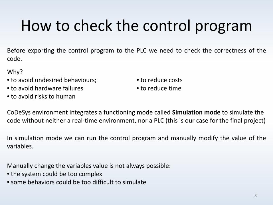
How to check the control programBefore exporting the control program to the PLC we need to check the correctness of thecode.
CoDeSys environment integrates a functioning mode called Simulation mode to simulate the code without neither a real-time environment, nor a PLC (this is our case for the final project)
Why?• to avoid undesired behaviours;• to avoid hardware failures• to avoid risks to human
• to reduce costs• to reduce time
In simulation mode we can run the control program and manually modify the value of thevariables.
Manually change the variables value is not always possible:• the system could be too complex• some behaviors could be too difficult to simulate
8

How to check the control programUsually a second program is built to simulate the real plant. We need to realize:• the virtual sensors (e.g. a position sensor, a level sensor,…)• the effect of the actuator (e.g. the increasing of the water if the valve is opened)
We can interact with the system during simulation building a graphic interface:
ControlProgram
PlantSimulator
Sensors measurements
ActuatorsSignals
• passively, showing only what is happening;• actively, manually changing the state of thesystem or the state of the controller (e.g. fillinga warehouse, changing the functioning modesof the controller if we want to work only somepieces instead of all, …).
9

The IEC 61131-3 standard can be seen as split in two parts:
Common Elements: Data Typing: definition of the data types (e.g.Integer, Real, Byte, Date, String, …). It is alsopossible to define own personal data types derivedfrom the previous Variables: depending on the visibility, 5 classesare defined (local, global, input, output, input-output). They are declared between the keywordVAR and END_VAR. The default value is 0 or FALSE.
Software Model: defines the structure of a control system basing on a maximum powerfulPLC (Multi-processor, multi-tasking, unlimited I/O, communication with other PLC and PCs).
• Configuration: represents the whole programmable controller (usually a PLC withseveral CPUs connected). In a control system we can have more than oneconfiguration communicating with each other. It contains one or several resources.• Resource: provides support functions for the execution of IEC programs and aninterface between a program, the I/O ports of the PLC and the user (like a CPU).
IEC 61131-3 compliant
10

• Task: controls the execution of a set of programs and/or function blocks. Programs/functionblocks must be associated to a task in order to be executed and can be executed periodicallyor can be event-driven. A task declaration consists of the task name, its priority, and acondition on which the task is to be executed (cyclic, time-controlled, event-controlled).
• POUs: (Program Organization Units) represent small independent software units containingthe program code. There exists three types of POUs: programs, functions and function blocks.The POUs enable a modular software structure with the possibility of software reuse.Similarly to the object oriented approach a POU must be declared and then instantiated oneor several times. A POU is programmed with a language defined in the standard and can beused by any other POUs (the recursive use is forbidden).
Programs: represents a set of software elements. Theinstances of a program can be assigned to several tasks.
Functions: are pre-programmed calculations that acceptnumerous inputs, but return only one output (INsOUT).It is always referred to its created name. Function blocks: are pre-programmed calculations that accept numerous inputs, andcan return several outputs. Differently from functions, a FB has an internal state so an“instance” of that block must be defined each time it is used in a POU (INs+STATEOUTs).
IEC 61131-3 compliant
11

Communication Model: describes the data exchange of configuration elements:• Acces Paths: enables the communication between configurations (VAR_ACCESS).• Local/Global Variables: symbolic names that have a mean for the user. Local variablesare variables usable only inside the POUs where are declared. Global variables areusable from each element inside the configuration.• Directly represented variables: refer to real addresses in the PLC memory.
IEC 61131-3 compliant
Note: Usually a conventionalPLC contains one resource,running one task, controllingone program, running in aclosed loop.
12
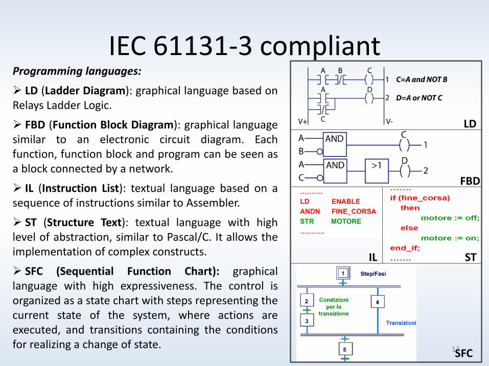
IEC 61131-3 compliantProgramming languages:
LD (Ladder Diagram): graphical language based onRelays Ladder Logic.
FBD (Function Block Diagram): graphical languagesimilar to an electronic circuit diagram. Eachfunction, function block and program can be seen asa block connected by a network.
IL (Instruction List): textual language based on asequence of instructions similar to Assembler.
ST (Structure Text): textual language with highlevel of abstraction, similar to Pascal/C. It allows theimplementation of complex constructs.
SFC (Sequential Function Chart): graphicallanguage with high expressiveness. The control isorganized as a state chart with steps representing thecurrent state of the system, where actions areexecuted, and transitions containing the conditionsfor realizing a change of state.
FBD
LD
IL ST
SFC13

1. Run CoDeSys v.2.3
First Steps
2. Create a new project (File New or press on the high left corner)
3. Select Target as None
4. Define the new POU•The default name is PLC_PRG.• It is automatically executed (the otherPOUs must be explicitly called).
14
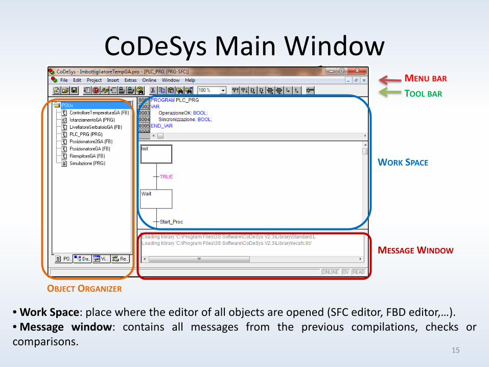
CoDeSys Main WindowMENU BAR
TOOL BAR
OBJECT ORGANIZER
WORK SPACE
MESSAGE WINDOW
• Work Space: place where the editor of all objects are opened (SFC editor, FBD editor,…).• Message window: contains all messages from the previous compilations, checks orcomparisons.
15

It has four register cards on the bottom:• POUs: contains the POUs defined as programs, functions and function blocks.• Data Types: lists the data types defined by the user.• Visualization: contains the graphic panel for HMI and for displaying the variables.• Resources: contains the elements for configuring and organizing the project (e.g. Global
Variables definition, Task configuration, Library Manager, PLC configuration, … )
Object Organizer
Important Note: to use the standard languages it is necessary to load the libraries namedIecsfc.lib and Standard.lib.
How to ?• Add a POU: right click on POUs in POUs card and Add Object.• Export a POU: right click on POUs and Export object.• Import a POU: click on Project in the Menu bar and Import.• Add a Library: Resource card Library Manager in thework space window right click Additional Library…• Append a new task: Resource Task Manager in the workspace window right click on Task configuration Append Task• Assign a program to a task: right click on the new taskcreated Append program call.
16

How to organize a projectUsually two programs are developed:
• Control program: defines the sequential logic control of the system (what we want).• Simulation program: simulates the behaviour of the system (it does not really exist).
The two programs interact with each other using global variables.Note: the control program can only use the measurements coming from the virtual sensors.
Other simulation variable cannot be used! 17

How to organize a projectBoth the programs have to be executed. Since only PLC_PRG is executed by default, we haveto configure the system:
1. Append a new task (right click on Task configurationAppend Task);2. Append two program calls for both the control and the simulation programs (right click
on New Task Append Program Call). 18
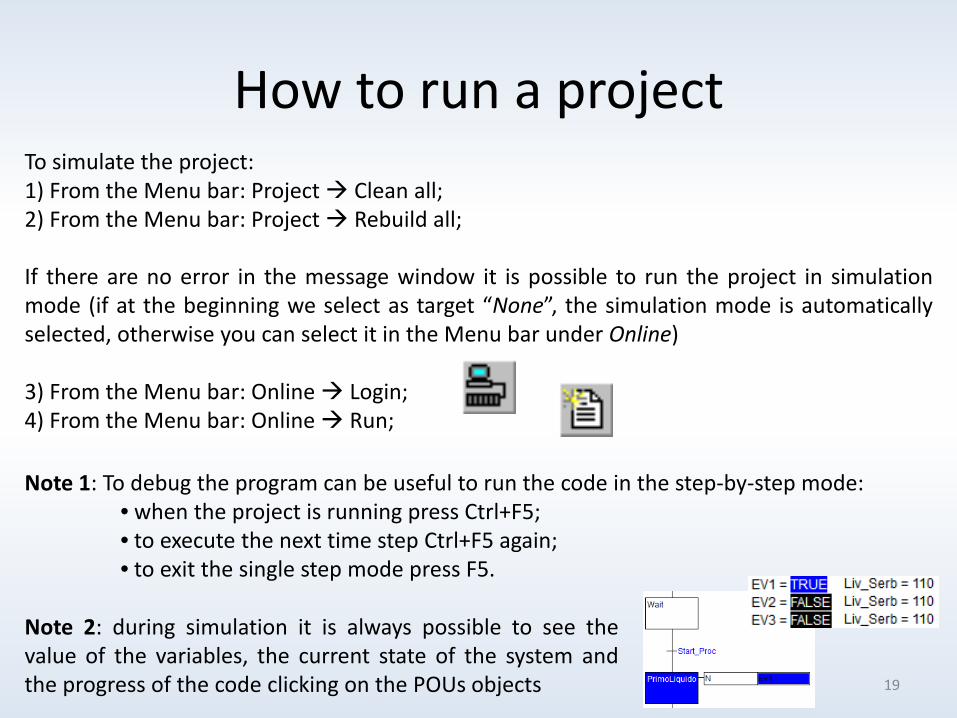
How to run a projectTo simulate the project:1) From the Menu bar: Project Clean all;2) From the Menu bar: Project Rebuild all;
If there are no error in the message window it is possible to run the project in simulationmode (if at the beginning we select as target “None”, the simulation mode is automaticallyselected, otherwise you can select it in the Menu bar under Online)
3) From the Menu bar: Online Login;4) From the Menu bar: Online Run;
Note 1: To debug the program can be useful to run the code in the step-by-step mode:• when the project is running press Ctrl+F5;• to execute the next time step Ctrl+F5 again;• to exit the single step mode press F5.
Note 2: during simulation it is always possible to see thevalue of the variables, the current state of the system andthe progress of the code clicking on the POUs objects 19

The SFC EditorThe easy way to develop the control program is using the SFC language. The editor simplifiesthe construction of the SFC.
Work space SFC Editor
INSERT STEPTRANSITIONS
INSERTALTERNATIVEBRANCH
INSERTPARALLELLBRANCH
INSERT JUMP
IF SELECTED A IEC STEP IS USEDINSTEAD OF A SIMPLIFIED ONE
The most important commands are found in the Tool bar (see figure below).
20

The SFC EditorDifferences between simplified step and IEC step
SIMPLIFIED STEP IEC STEP
• Actions are inside the block anddirectly connected with the step (actionis executed until the step is active);• The instructions of the action can bewritten directly inside the block;
• Actions are outside the block with thetime qualifier;• In the action field we can put a booleanvariable or an action previously definedand appended in the Object Organizerunder the program which uses it;
N (Non-stored): The action is active as long as the stepR (overriding Reset): The action is deactivatedS (Set / Stored): The action is activated and remains active until a ResetL (time Limited): The action is activated for a certain timeD (time Delayed): The action becomes active after a certain time if the step is still active and then it remains active as long as the step is active.P (Pulse): The action is executed just one time if the step is activeSD (Stored and time Delayed): The action is activated after a certain time and remains active until a ResetDS (Delayed and Stored): The action is activated after a certain time as long as the step is still active and remains active up to a ResetSL (Stored and time Limited): The action is activated for a certain time
Right click on the desired program Add Action21
The SFC Editor
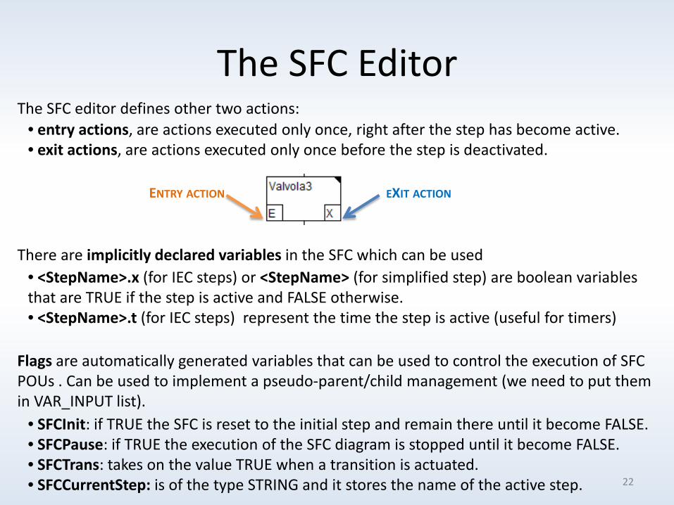
• <StepName>.x (for IEC steps) or <StepName> (for simplified step) are boolean variables that are TRUE if the step is active and FALSE otherwise.• <StepName>.t (for IEC steps) represent the time the step is active (useful for timers)
There are implicitly declared variables in the SFC which can be used
• entry actions, are actions executed only once, right after the step has become active.• exit actions, are actions executed only once before the step is deactivated.
The SFC editor defines other two actions:
ENTRY ACTION EXIT ACTION
• SFCInit: if TRUE the SFC is reset to the initial step and remain there until it become FALSE.• SFCPause: if TRUE the execution of the SFC diagram is stopped until it become FALSE.• SFCTrans: takes on the value TRUE when a transition is actuated.• SFCCurrentStep: is of the type STRING and it stores the name of the active step.
Flags are automatically generated variables that can be used to control the execution of SFC POUs . Can be used to implement a pseudo-parent/child management (we need to put them in VAR_INPUT list).
22

Parent/Child Management• SFCs called child depend on another SFC called parent.• Parent SFC can force the start and the stop of the children.• The children execute in parallel with the parent SFC if activated.
Parent/child Management:
23
If we put the flag variable as VAR_INPUT in a program all the programs in the project canmodify this variables. We can obtain a pseudo-parent/child management.
With SFCInit we can activate or deactivate a SFC.With SFCPause we can freeze a SFC
Why pseudo?• all the programs can modify the flag variable not only the parent (we have several parent);• when the child is stopped it does not disappear but it remains frozen in the init state.
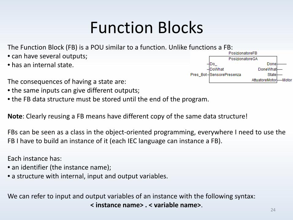
Function Blocks
The consequences of having a state are:• the same inputs can give different outputs;• the FB data structure must be stored until the end of the program.
The Function Block (FB) is a POU similar to a function. Unlike functions a FB:• can have several outputs;• has an internal state.
Note: Clearly reusing a FB means have different copy of the same data structure!
FBs can be seen as a class in the object-oriented programming, everywhere I need to use theFB I have to build an instance of it (each IEC language can instance a FB).
Each instance has:• an identifier (the instance name);• a structure with internal, input and output variables.
We can refer to input and output variables of an instance with the following syntax:< instance name> . < variable name>.
24

Function BlocksTo use a FB we have to:• Declare the FB type:
ALGORITHMDECLARATION
VARIABLESDECLARATION
• Declare an instance:
• Call the FB instance: in a FBD program: in a LD program: in a ST program:
25
VisualizationA visualization is a graphical representation of the project variables which allows also theinteraction with the PLC program during the simulation via mouse and keypad.
26
A graphic editor allows to connect visualization elements with project variables throughconfiguration windows.
A visualization created in CoDeSys can be used for testing and interacting with the controlsoftware in simulation mode, but also:
• for operating the visualization in full screen mode on a PLC computer with CoDeSys HMI (aruntime system not available in the demo version).
• for interacting with the controller via internet with a Web-Visualization (useful for remotemaintenance purposes)
• for visualizations which can be started directly on the PLC as a Target-Visualization.

How to create a visualization objectTo create a visualization object:• click on the Visualization register in the Object Organizer.
• right click on Visualizations folder Add Object…
• insert visualization elements using the Menu bar.
• Double click on the element to open the configurationwindow.
27

Example
SOLENOIDVALVES
CONVEYERMOTOR
RESISTOR
TANKLEVELSENSOR
TEMPERATURESENSOR
POSITIONSENSOR
BOTTLE LEVELSENSOR
START/STOP
28

Sensors DescriptionStart 1=process starts; 0=otherwisePres_bottle 1=bottle in position; 0=otherwiseTemp_val Temperature valueTank_lev Fluid level in the tankBot_lev Fluid level in the bottle
Actuators DescriptionMotor Conveyor motor on/off signalHot Resistor on/off signalEV1
Solenoid valves on/off signalsEV2EV3
Example
29

References• “User Manual for PLC Programming with CoDeSys 2.3”, 3S - Smart Software Solutions GmbH
• 3S web page, http://www.3s-software.com/index.shtml?homepage
• M. Sartini, “Manuale di utilizzo del software CoDeSys” (Italian)
• The example is on http://www-lar.deis.unibo.it/people/msartini/
30